WO2022224332A1 - 情報処理装置、車両制御システム、情報処理方法、及び非一時的なコンピュータ可読媒体 - Google Patents
情報処理装置、車両制御システム、情報処理方法、及び非一時的なコンピュータ可読媒体 Download PDFInfo
- Publication number
- WO2022224332A1 WO2022224332A1 PCT/JP2021/015971 JP2021015971W WO2022224332A1 WO 2022224332 A1 WO2022224332 A1 WO 2022224332A1 JP 2021015971 W JP2021015971 W JP 2021015971W WO 2022224332 A1 WO2022224332 A1 WO 2022224332A1
- Authority
- WO
- WIPO (PCT)
- Prior art keywords
- vehicle
- captured image
- control
- motion
- user
- Prior art date
- Legal status (The legal status is an assumption and is not a legal conclusion. Google has not performed a legal analysis and makes no representation as to the accuracy of the status listed.)
- Ceased
Links
Images











Classifications
-
- G—PHYSICS
- G06—COMPUTING OR CALCULATING; COUNTING
- G06F—ELECTRIC DIGITAL DATA PROCESSING
- G06F3/00—Input arrangements for transferring data to be processed into a form capable of being handled by the computer; Output arrangements for transferring data from processing unit to output unit, e.g. interface arrangements
- G06F3/01—Input arrangements or combined input and output arrangements for interaction between user and computer
- G06F3/017—Gesture based interaction, e.g. based on a set of recognized hand gestures
-
- B—PERFORMING OPERATIONS; TRANSPORTING
- B60—VEHICLES IN GENERAL
- B60R—VEHICLES, VEHICLE FITTINGS, OR VEHICLE PARTS, NOT OTHERWISE PROVIDED FOR
- B60R25/00—Fittings or systems for preventing or indicating unauthorised use or theft of vehicles
- B60R25/20—Means to switch the anti-theft system on or off
- B60R25/2045—Means to switch the anti-theft system on or off by hand gestures
-
- B—PERFORMING OPERATIONS; TRANSPORTING
- B60—VEHICLES IN GENERAL
- B60R—VEHICLES, VEHICLE FITTINGS, OR VEHICLE PARTS, NOT OTHERWISE PROVIDED FOR
- B60R25/00—Fittings or systems for preventing or indicating unauthorised use or theft of vehicles
- B60R25/20—Means to switch the anti-theft system on or off
- B60R25/25—Means to switch the anti-theft system on or off using biometry
-
- G—PHYSICS
- G06—COMPUTING OR CALCULATING; COUNTING
- G06F—ELECTRIC DIGITAL DATA PROCESSING
- G06F3/00—Input arrangements for transferring data to be processed into a form capable of being handled by the computer; Output arrangements for transferring data from processing unit to output unit, e.g. interface arrangements
- G06F3/01—Input arrangements or combined input and output arrangements for interaction between user and computer
- G06F3/011—Arrangements for interaction with the human body, e.g. for user immersion in virtual reality
- G06F3/013—Eye tracking input arrangements
-
- G—PHYSICS
- G06—COMPUTING OR CALCULATING; COUNTING
- G06V—IMAGE OR VIDEO RECOGNITION OR UNDERSTANDING
- G06V20/00—Scenes; Scene-specific elements
- G06V20/50—Context or environment of the image
- G06V20/56—Context or environment of the image exterior to a vehicle by using sensors mounted on the vehicle
- G06V20/58—Recognition of moving objects or obstacles, e.g. vehicles or pedestrians; Recognition of traffic objects, e.g. traffic signs, traffic lights or roads
-
- G—PHYSICS
- G06—COMPUTING OR CALCULATING; COUNTING
- G06V—IMAGE OR VIDEO RECOGNITION OR UNDERSTANDING
- G06V40/00—Recognition of biometric, human-related or animal-related patterns in image or video data
- G06V40/10—Human or animal bodies, e.g. vehicle occupants or pedestrians; Body parts, e.g. hands
- G06V40/16—Human faces, e.g. facial parts, sketches or expressions
- G06V40/172—Classification, e.g. identification
-
- G—PHYSICS
- G06—COMPUTING OR CALCULATING; COUNTING
- G06V—IMAGE OR VIDEO RECOGNITION OR UNDERSTANDING
- G06V40/00—Recognition of biometric, human-related or animal-related patterns in image or video data
- G06V40/20—Movements or behaviour, e.g. gesture recognition
- G06V40/28—Recognition of hand or arm movements, e.g. recognition of deaf sign language
-
- G—PHYSICS
- G07—CHECKING-DEVICES
- G07C—TIME OR ATTENDANCE REGISTERS; REGISTERING OR INDICATING THE WORKING OF MACHINES; GENERATING RANDOM NUMBERS; VOTING OR LOTTERY APPARATUS; ARRANGEMENTS, SYSTEMS OR APPARATUS FOR CHECKING NOT PROVIDED FOR ELSEWHERE
- G07C9/00—Individual registration on entry or exit
- G07C9/00174—Electronically operated locks; Circuits therefor; Nonmechanical keys therefor, e.g. passive or active electrical keys or other data carriers without mechanical keys
- G07C9/00563—Electronically operated locks; Circuits therefor; Nonmechanical keys therefor, e.g. passive or active electrical keys or other data carriers without mechanical keys using personal physical data of the operator, e.g. finger prints, retinal images, voicepatterns
-
- G—PHYSICS
- G07—CHECKING-DEVICES
- G07C—TIME OR ATTENDANCE REGISTERS; REGISTERING OR INDICATING THE WORKING OF MACHINES; GENERATING RANDOM NUMBERS; VOTING OR LOTTERY APPARATUS; ARRANGEMENTS, SYSTEMS OR APPARATUS FOR CHECKING NOT PROVIDED FOR ELSEWHERE
- G07C9/00—Individual registration on entry or exit
- G07C9/00174—Electronically operated locks; Circuits therefor; Nonmechanical keys therefor, e.g. passive or active electrical keys or other data carriers without mechanical keys
- G07C9/00571—Electronically operated locks; Circuits therefor; Nonmechanical keys therefor, e.g. passive or active electrical keys or other data carriers without mechanical keys operated by interacting with a central unit
Definitions
- the present disclosure relates to an information processing device, a vehicle control system, an information processing method, and a non-transitory computer-readable medium, and more particularly to an information processing device, a vehicle control system, an information processing method, and a non-transitory computer-readable medium for controlling a vehicle. Regarding the medium.
- Patent Literature 1 the method described in Patent Literature 1 is not convenient because it requires an electronic key to unlock the vehicle door, and if the electronic key is stolen, the vehicle door cannot be unlocked. I had a problem.
- Patent Document 3 a registered user is detected from a captured image around a vehicle based on the gait of a person in the vicinity, a line-of-sight direction of the registered user is detected from the captured image, and a door door is detected based on the line-of-sight direction.
- a control device for a vehicle is disclosed that changes the switch from a closed state to an open state.
- Patent Document 2 does not disclose such a door opening/closing operation, and the convenience is insufficient. It should be noted that the same applies to other operations that require the user's intention, in addition to the door opening/closing operation.
- Patent Document 3 does not disclose unlocking the vehicle door without using the electronic key, which is inadequate in terms of convenience.
- An object of the present disclosure is to provide an information processing device, a vehicle control system, an information processing method, and a non-temporary computer-readable medium that improve the convenience of operating a vehicle in view of the problems described above.
- An information processing device includes first authentication means, first vehicle control means, motion determination means, and second vehicle control means.
- the first authentication means controls biometric authentication of a person included in the first captured image based on the first captured image generated by capturing the scenery around the vehicle, and controls the biometric authentication of the person included in the first captured image. Determine whether the included person is a registered user.
- the first vehicle control means when it is determined that the person included in the first photographed image is the registered user, performs first control related to unlocking of the opening/closing member of the vehicle. Send a signal.
- the motion determination means determines whether the motion of the person included in the second captured image is a registered motion, based on a second captured image generated by capturing the scenery around the vehicle or the interior of the vehicle.
- the second vehicle control means transmits a second control signal for executing second control when the action of the person included in the second captured image is the registered action.
- the second control is different from the first control, being a second control according to the action of the person with respect to a predetermined opening/closing member of the vehicle or the power source of the vehicle.
- a vehicle control system includes a biometric authentication device that performs biometric authentication, and an information processing device.
- the information processing device includes first authentication means, first vehicle control means, motion determination means, and second vehicle control means.
- the first authentication means causes the biometric authentication device to perform biometric authentication of a person included in the first captured image based on the first captured image generated by capturing the scenery around the vehicle, and It is determined whether or not the person included in the first captured image is a registered user.
- the first vehicle control means when it is determined that the person included in the first photographed image is the registered user, performs first control related to unlocking of the opening/closing member of the vehicle. Send a signal.
- the motion determination means determines whether the motion of the person included in the second captured image is a registered motion, based on a second captured image generated by capturing the scenery around the vehicle or the interior of the vehicle. It controls the motion judgment of
- the second vehicle control means transmits a second control signal for executing second control when the action of the person included in the second captured image is the registered action.
- the second control is different from the first control, being a second control according to the action of the person with respect to a predetermined opening/closing member of the vehicle or the power source of the vehicle.
- An information processing method includes a first authentication stage, a first vehicle control stage, an operation determination stage, and a second vehicle control stage.
- the first authentication step controls biometric authentication of a person included in the first captured image based on the first captured image generated by capturing the scenery around the vehicle, It is the step of determining whether the person involved is a registered user.
- first vehicle control step when it is determined that the person included in the first photographed image is the registered user, first control for unlocking the opening/closing member of the vehicle is executed. This is the step of transmitting the signal.
- the motion determination step determines whether or not the motion of the person included in the second captured image is a registered motion, based on a second captured image generated by capturing the scenery around the vehicle or the interior of the vehicle. This is the step of controlling the motion determination.
- the second vehicle control step is a step of transmitting a second control signal for executing a second control when the motion of the person included in the second captured image is the registered motion.
- the second control is different from the first control, being a second control according to the action of the person with respect to a predetermined opening/closing member of the vehicle or the power source of the vehicle.
- a non-transitory computer-readable medium includes a program for causing a computer to perform a first authentication stage, a first vehicle control stage, an operation determination stage, and a second vehicle control stage.
- the first authentication step controls biometric authentication of a person included in the first captured image based on the first captured image generated by capturing the scenery around the vehicle, It is the step of determining whether the person involved is a registered user.
- first vehicle control step when it is determined that the person included in the first photographed image is the registered user, first control for unlocking the opening/closing member of the vehicle is executed. This is the step of transmitting the signal.
- the motion determination step determines whether or not the motion of the person included in the second captured image is a registered motion, based on a second captured image generated by capturing the scenery around the vehicle or the interior of the vehicle. This is the step of controlling the motion determination.
- the second vehicle control step is a step of transmitting a second control signal for executing a second control when the motion of the person included in the second captured image is the registered motion.
- the second control is different from the first control, being a second control according to the action of the person with respect to a predetermined opening/closing member of the vehicle or the power source of the vehicle.
- an information processing device a vehicle control system, an information processing method, and a non-temporary computer-readable medium that improve the convenience of operating a vehicle.
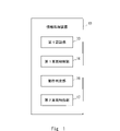
- FIG. 1 is a block diagram showing the configuration of an information processing apparatus according to a first embodiment;
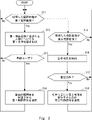
- FIG. 4 is a flowchart showing the flow of information processing according to the first embodiment;
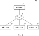
- 1 is a block diagram showing the overall configuration of a vehicle control system according to a second embodiment;
- FIG. 2 is a block diagram showing the configuration of a face authentication device according to a second embodiment;
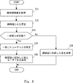
- FIG. 9 is a flowchart showing the flow of face information registration processing according to the second embodiment;
- 9 is a flow chart showing the flow of face authentication processing according to the second embodiment;
- 2 is a schematic configuration diagram of an in-vehicle system according to a second embodiment;
- FIG. 2 is a block diagram showing the configuration of an in-vehicle system according to a second embodiment;
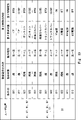
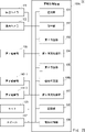
- FIG. 10 is a diagram showing an example of the data structure of user information according to the second embodiment;
- FIG. 10 is a diagram showing an example of the data structure of an action table according to the second embodiment;
- FIG. 9 is a flowchart showing the flow of registration processing according to the second embodiment;
- 9 is a flowchart showing the flow of control processing according to the second embodiment;
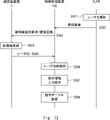
- FIG. 11 is a sequence diagram showing an example of the flow of registration processing according to the second embodiment;
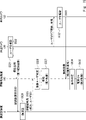
- FIG. 11 is a sequence diagram showing an example of the flow of control processing according to the second embodiment;
- FIG. 11 is a sequence diagram showing another example of the flow of control processing according to the second embodiment;
- FIG. 11 is a block diagram showing the configuration of an in-vehicle system according to Embodiment 3;
- FIG. 11 is a diagram showing an example of user positions according to the third embodiment;
- FIG. FIG. 11 is a diagram showing another example of user positions according to the third embodiment;
- FIG. 12 is a diagram showing an example of the data structure of an action table according to the third embodiment;
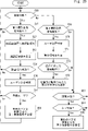
- FIG. FIG. 11 is a flowchart showing an example of the flow of control processing according to the third embodiment;
- FIG. 11 is a block diagram showing the configuration of an in-vehicle system according to a fourth embodiment;
- FIG. FIG. 13 is a flowchart showing an example of the flow of control processing according to the fourth embodiment;
- FIG. FIG. 11 is a block diagram showing the configuration of an in-vehicle system according to Embodiment 5;
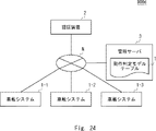
- FIG. 12 is a block diagram showing the overall configuration of a vehicle control system according to a sixth embodiment
- FIG. FIG. 14 is a diagram showing an example of the data structure of a motion determination model table according to the sixth embodiment
- FIG. It is a figure which shows the structural example of a computer.
- Patent Document 1 discloses a method of unlocking a vehicle door using an electronic key and face authentication.
- the electronic key is required to unlock the vehicle door, which poses a problem of insufficient convenience.
- the present embodiment is made to solve such problems.
- FIG. 1 is a block diagram showing the configuration of an information processing apparatus 10 according to the first embodiment.
- the information processing device 10 is a computer for executing unlocking control of an opening/closing member of the vehicle and various other controls related to the vehicle.
- the information processing device 10 acquires a captured image generated by capturing the scenery around the vehicle or a captured image generated by capturing the interior of the vehicle, and executes the above-described control based on the acquired captured image. do.
- a photographed image generated by photographing the scenery around the vehicle under a predetermined condition is called a first photographed image.
- the first captured image is a captured image generated by capturing the scenery around the vehicle when the opening/closing member of the vehicle is in the locked state.
- a captured image generated by capturing the scenery around the vehicle or the interior of the vehicle under predetermined conditions is referred to as a second captured image.
- the second captured image is a captured image generated by capturing the scenery around the vehicle when the opening/closing member of the vehicle is in the unlocked state.
- the information processing device 10 includes a first authentication section 13 , a first vehicle control section 14 , an operation determination section 16 and a second vehicle control section 17 .
- the first authentication unit 13 is also called first authentication means. Based on the first captured image, the first authentication unit 13 controls biometric authentication of the person included in the first captured image, and determines whether or not the person included in the first captured image is a registered user. . Also, controlling biometric authentication may mean that the first authentication unit 13 performs biometric authentication, or the first authentication unit 13 causes another device, for example, a biometric authentication device to perform biometric authentication. There may be.
- biometric authentication is biometric authentication that can extract biometric information from a captured image, such as face authentication, iris authentication, vein authentication, and auricle authentication.
- the first vehicle control unit 14 is also called first vehicle control means.
- the first vehicle control unit 14 transmits a first control signal for executing the first control when it is determined that the person included in the first captured image is the registered user.
- the first control is control related to unlocking of the opening/closing body of the vehicle.
- the motion determination unit 16 is also called motion determination means. Based on the second captured image, the motion determination unit 16 controls motion determination as to whether or not the motion of the person included in the second captured image is the registered motion. Further, controlling the motion determination may mean that the motion determination unit 16 executes the motion determination, or that the motion determination unit 16 causes another device, such as a motion determination device, to perform the motion determination. good too.
- the second vehicle control unit 17 is also called second vehicle control means.
- the second vehicle control unit 17 transmits a second control signal for executing second control regarding the vehicle when the action of the person included in the second captured image is the registered action.
- the second control is control for a predetermined opening/closing member of the vehicle or the power source of the vehicle, and is control different from the first control.
- the second control is determined according to the motion of the person.
- the predetermined opening/closing body of the vehicle may be the same as the opening/closing body of the vehicle controlled by the first control, or may be a part of the opening/closing body of the vehicle controlled by the first control. However, it may be another opening/closing member included in the vehicle.
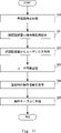
- FIG. 2 is a flowchart showing the flow of information processing according to the first embodiment.
- the first authentication unit 13 of the information processing device 10 determines whether or not the captured image acquired by the information processing device 10 is the first captured image generated by capturing the scenery around the vehicle ( S11). If the captured image acquired by the information processing apparatus 10 is the first captured image (Yes in S11), the first authentication unit 13 performs biometric authentication of the person included in the first captured image based on the first captured image. is controlled (S12). Next, the first authentication unit 13 determines whether or not the person included in the first captured image is a registered user based on the result of biometric authentication (S13).
- the first vehicle control unit 14 transmits a first control signal for unlocking the opening/closing member of the vehicle ( S14), the process returns to step S11.
- the first authentication unit 13 directly returns the process to step S11.
- the motion determination unit 16 selects the second captured image generated by capturing the scenery around the vehicle or the interior of the vehicle. (S15). If the captured image acquired by the information processing device 10 is not the second captured image (No in S15), the motion determination unit 16 returns the process to step S11. On the other hand, if the information processing device 10 is the second captured image (Yes in S15), the motion determination unit 16 controls motion determination of the person included in the second captured image based on the second captured image (S16 ). If the motion of the person included in the second captured image is the registered motion (Yes in S17), the second vehicle control unit 17 transmits a second control signal for executing second control according to the motion. (S18), the process returns to step S11. On the other hand, if the motion of the person included in the second captured image is not the registered motion (No in S17), the motion determination unit 16 returns the process to step S11.
- the information processing device 10 executes control for unlocking the opening/closing member of the vehicle by biometric authentication, and executes control other than unlocking of the vehicle by operation determination. This allows the user to unlock the doors of the vehicle and perform other operations related to the vehicle in a non-contact manner without using the electronic key.
- the information processing apparatus 10 performs control other than unlocking the vehicle based on the user's intention based on the operation determination, so compared to the method of unlocking and opening the door when the biometric authentication is successful. , it is possible to avoid a situation in which the door is unintentionally opened.
- the information processing apparatus 10 can cope with a case where the user only wishes to unlock the door, compared to the method of unlocking and opening the door by two-factor authentication of biometric authentication and action. Therefore, the convenience of operating the vehicle is improved.
- FIG. 3 is a block diagram showing the overall configuration of a vehicle control system 900 according to the second embodiment.
- a vehicle control system 900 is a computer system for implementing various vehicle-related controls using biometric authentication.
- Various controls related to the vehicle include controls for unlocking or locking the opening/closing member of the vehicle, and other controls that require user's intention.
- the opening/closing body may be a front door, a rear door, a bonnet, a fuel filler cover, a door glass (window), a trunk cover, or the like.
- control for unlocking the opening/closing body of the vehicle is referred to as first control
- control for locking the opening/closing body of the vehicle is referred to as third control
- other control that requires the user's intention is referred to as second control.
- the second control may be, for example, control for opening or closing the opening/closing body of the vehicle, or starting or stopping the power source of the vehicle.
- the vehicle power source may be an ignition power source (IG power source) or an accessory power source (ACC power source).
- biometric authentication is face authentication.
- the biometric authentication may be iris authentication, vein authentication, auricle authentication, or other biometric authentication capable of extracting biometric information from a photographed image.
- the vehicle control system 900 includes in-vehicle systems 1-1, 1-2, 1-3 and a face authentication device 2, which are connected via a network N so as to be communicable.
- the network N is a wired or wireless communication line.
- the in-vehicle systems 1-1, 1-2, and 1-3 are respectively mounted on different vehicles, and each performs the first control, second control, and third control of the corresponding vehicle.
- the in-vehicle systems 1-1, 1-2, and 1-3 may simply be referred to as the in-vehicle system 1 when referred to without distinction.
- the number of in-vehicle systems 1 included in the vehicle control system 900 is not limited to three.
- the in-vehicle system 1 controls face authentication and executes first control based on the result of face authentication.
- face authentication is performed by the face authentication device 2 . Therefore, the in-vehicle system 1 controls face authentication by transmitting a face authentication request for the user U, who is a person to be authenticated, to the face authentication device 2 and receiving a face authentication result from the face authentication device 2 .
- the face authentication request includes a face image, which is a photographed image including at least the face area of the user U, but may include face information extracted from the face image instead of the face image.
- the in-vehicle system 1 also determines the motion of the user U who is the person to be authenticated, and executes the second control based on the motion determination result.
- the in-vehicle system 1 also executes the third control under predetermined conditions.
- the face authentication device 2 is an example of a biometric authentication device that performs biometric authentication.
- the face authentication device 2 is an information processing device that stores face information of a plurality of persons.
- the face authentication device 2 compares the face image or face information included in the request with the face information of each user U, and sends the matching result (face authentication result) to the requester. Reply to
- FIG. 4 is a block diagram showing the configuration of the face authentication device according to the second embodiment.
- the face authentication device 2 includes a face information database (DB) 210 , a detection section 220 , a feature point extraction section 230 , a registration section 240 and an authentication section 250 .
- the face information DB 210 associates and stores a user ID 211 and face feature information 212 of the user ID.
- the facial feature information 212 is a set of feature points extracted from a facial image, and is an example of facial information.
- the detection unit 220 detects a face area included in a registration image for registering face information, and supplies it to the feature point extraction unit 230 .
- the feature point extraction unit 230 extracts feature points from the face area detected by the detection unit 220 and supplies face feature information to the registration unit 240 .
- the feature point extraction unit 230 also extracts feature points included in the face image for authentication, and supplies face feature information to the authentication unit 250 .
- the registration unit 240 newly issues a user ID 211 when registering facial feature information.
- the registration unit 240 associates the issued user ID 211 with the facial feature information 212 extracted from the registered image and registers them in the facial information DB 210 .
- Authentication unit 250 performs face authentication using facial feature information 212 . Specifically, the authentication unit 250 collates the facial feature information extracted from the facial image with the facial feature information 212 in the facial information DB 210 .
- the authentication unit 250 replies to the information processing apparatus 100 whether or not the facial feature information matches. Whether the facial feature information matches or not corresponds to the success or failure of the authentication. Note that matching of facial feature information (matching) means a case where the degree of matching is equal to or greater than a predetermined value.
- FIG. 5 is a flowchart showing the flow of face information registration processing according to the second embodiment.
- the face authentication device 2 acquires the registered image of the user U included in the face information registration request (S21). For example, the face authentication device 2 receives a face information registration request via the network N from the information processing device 100 or a user terminal (not shown).
- the detection unit 220 detects a face area included in the registered image (S22).
- the feature point extraction unit 230 extracts feature points from the face area detected in step S22, and supplies face feature information to the registration unit 240 (S23).
- the registration unit 240 issues a user ID 211, associates the user ID 211 with the facial feature information 212, and registers them in the facial information DB 210 (S24).
- the face authentication device 2 may receive the face feature information 212 from the face information registration requester and register it in the face information DB 210 in association with the user ID 211 .
- FIG. 6 is a flowchart showing the flow of face authentication processing according to the second embodiment.
- the feature point extraction unit 230 acquires facial feature information for authentication (S31).
- the face authentication device 2 receives a face authentication request from the information processing device 100 via the network N, and extracts facial feature information from the captured image included in the face authentication request in steps S21 to S23.
- the face authentication device 2 may receive facial feature information from the information processing device 100 .
- the authentication unit 250 collates the acquired facial feature information with the facial feature information 212 of the facial information DB 210 (S32).
- the authentication unit 250 identifies the user ID 211 of the user whose facial feature information matches (S34). . Then, the authenticating unit 250 sends back to the information processing apparatus 100 the fact that the face authentication was successful and the specified user ID 211 as the face authentication result (S35). If there is no matching face feature information (No in S33), the authentication unit 250 returns a face authentication result to the information processing apparatus 100 to the effect that the face authentication has failed (S36).
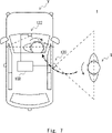
- FIG. 7 is a schematic configuration diagram of the in-vehicle system 1 according to the second embodiment.
- the in-vehicle system 1 is mounted on a vehicle V.
- the in-vehicle system 1 includes at least an information processing device 100 and an in-vehicle camera mounted on the vehicle V.
- the vehicle-mounted camera is connected to the information processing device 100 .
- there are a plurality of in-vehicle cameras and the plurality of in-vehicle cameras include a peripheral camera 120 that captures the surrounding scenery outside the vehicle V and an in-vehicle camera 122 that captures the interior of the vehicle V.
- the information processing apparatus 100 controls face authentication based on the first captured image, and determines whether or not the user U is a predetermined registered user.
- the information processing apparatus 100 controls to unlock the door (first control). Note that face recognition for unlocking the door is sometimes called first face recognition.
- the user U When the door is unlocked, the user U performs a predetermined action (gesture). At this time, the peripheral camera 120 photographs the user U located in the vicinity of the vehicle V and generates a second photographed image.
- the second captured image is an image different from the above-described first captured image, but may be the same image.
- the information processing apparatus 100 controls motion determination as to whether or not the motion of the user U is a registered motion that has been registered in advance, based on the second captured image.
- the information processing apparatus 100 determines that the motion of the user U is the registration motion
- the information processing apparatus 100 executes the second control according to the motion of the user U. Note that the target and type of the second control may be determined according to the registration operation.
- the information processing apparatus 100 opens the door of the passenger seat, and the user U performs an action of changing the direction of the line of sight from the bottom to the top.
- the information processing apparatus 100 may activate the IG power supply.
- the second captured image may be captured when the user U is inside the vehicle. For example, when the door is unlocked, the user U opens the door of the driver's seat and gets into the driver's seat. The user U then performs a predetermined action. At this time, the in-vehicle camera 122 captures an image of the user U located in the interior of the vehicle V and generates a second captured image. Then, the information processing apparatus 100 controls motion determination as to whether or not the motion of the user U is a registered motion that has been registered in advance, based on the second captured image. When the information processing apparatus 100 determines that the motion of the user U is the registration motion, the information processing apparatus 100 executes the second control according to the motion of the user U. For example, when the user U performs an action of changing the direction of the line of sight from the bottom to the top, the information processing device 100 may turn on the IG power of the vehicle V. FIG.
- the information processing device 100 controls the door to be locked when a predetermined time has elapsed since the door was closed (third control).
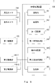
- FIG. 8 is a block diagram showing the configuration of the in-vehicle system 1 according to the second embodiment.
- the in-vehicle system 1 includes an information processing device 100, a peripheral camera 120, an in-vehicle camera 122, a first driving section 130, and second driving sections 140-1 and 140-5.
- the information processing device 100 is an example of the information processing device 10 described above.
- Information processing apparatus 100 includes registration unit 101, acquisition unit 102, first authentication unit 103, first vehicle control unit 104, motion determination unit 106, second vehicle control unit 107, and storage unit 108. have.
- the registration unit 101 is also called registration means.
- the registration unit 101 transmits a face information registration request including the registration image to the face authentication device 2 via the network N.
- the registration unit 101 stores the user ID issued by the face authentication device 2 at the time of registration of the face information in the storage unit 108 as user information.
- the user ID recorded as user information is the user ID of the registered user of the vehicle V.
- FIG. 9 is a diagram showing an example of the data structure of user information according to the second embodiment.
- the user information includes a user ID for each registration ID.
- the registration unit 101 registers an action for executing the second control in the action table.
- a registered action is called a registered action.
- 10 is a diagram illustrating an example of a data structure of an operation table according to the second embodiment; FIG.
- the action table associates the content of the registered action with the content of the second control.
- the content of a registered action is information that associates an action target with an action type, and is identified by an action ID.
- the motion target is the body or a part of the body to be moved, and in this figure, it is the face or line of sight of the person. However, the motion target is not limited to this, and may be a hand.
- the action type is information indicating how to move the action target.
- the action type may be "change direction” such as “change direction from right to left” or “change direction from up to down”. Further, the action type may be "(the body) approaches the vehicle V". Further, the action type may be "touching the face area or a specific area around the face” such as “touching the ear (with a hand)” or “touching the nose (with a hand)”.
- the content of one registered action may consist of one set of action targets and action types, or may consist of a plurality of sets of action targets and action types.
- the content of the registration operation is determined based on at least one of the orientation of the face and the orientation of the line of sight of the person. good.
- the registered action may be that the person "touches the ear, nose, and mouth in this order.”
- the content of the second control is information that associates the second controlled object with the second control type.
- the second controlled object is a part of the vehicle V to be controlled by the second control, and in this figure is the door or the IG power supply.
- the second controlled object is not limited to this, and may be other opening/closing bodies such as a door glass, a bonnet, a fuel filler port cover or a trunk cover, or other power sources such as an ACC power source.
- the second control type is information indicating how to control the second controlled object.
- the second control type may be a control related to opening and closing such as "opening (opening/closing body)” or “closing (opening/closing body)", or “activating (power supply)” or “(power supply) It may be a control related to starting/stopping the power supply such as "stop”. That is, the contents of the second control are door opening, door closing, IG power activation, IG power deactivation, ACC power activation, ACC power deactivation, fuel filler cover open, fuel filler cover closed, trunk cover open, trunk It may be cover closed, bonnet open, bonnet closed, door glass (window) open, or door glass closed.
- the content of one second control may be composed of one set of the second controlled object and the second control type, or may be composed of a plurality of sets of the second controlled object and the second control type. That is, the content of the second control is determined based on at least one of the opening or closing of the opening/closing member and the activation or deactivation of the power source, and may be, for example, "opening the door and activating the IG power source.”
- the direction of control indicated by the second control type may be determined in advance so as to correspond to the direction of change indicated by the action type. That is, when the motion target is the face or the line of sight, the content of the second control indicates control for opening and closing the opening/closing body of the vehicle V in the direction corresponding to the direction of the line of sight indicated by the type of motion or the direction of the face. good. For example, if the content of the registered action is "to change the orientation of the face from right to left", the content of the second control is "to open the sliding door by sliding it from right to left”. good. As a result, the user U only needs to perform an intuitive action, which improves operability.
- Acquisition unit 102 is also called acquisition means. Acquisition unit 102 is connected to peripheral camera 120 and in-vehicle camera 122 and acquires captured images from peripheral camera 120 and in-vehicle camera 122 . When the doors of the vehicle V are locked, the acquisition unit 102 supplies the captured image acquired from the peripheral camera 120 to the first authentication unit 103 as the first captured image. Further, when the doors of the vehicle V are unlocked, the acquisition unit 102 supplies the captured image acquired from the peripheral camera 120 or the vehicle interior camera 122 to the motion determination unit 106 as the second captured image. Note that the second captured image is an image captured at a timing different from that of the first captured image. The same image as the first captured image may be supplied to the motion determination unit 106 as the second captured image.
- the acquisition unit 102 may continuously acquire captured images from the peripheral camera 120 and the in-vehicle camera 122 at predetermined time intervals. In this case, when the doors of the vehicle V are locked and the predetermined first captured image acquisition condition is satisfied, the acquisition unit 102 uses the captured image acquired from the peripheral camera 120 as the first captured image as the first captured image. It may be supplied to the authentication unit 103 .
- the first captured image acquisition condition may also be called a first authentication start condition.
- the first captured image acquisition condition may be that the user U included in the captured image captured by the peripheral camera 120 is positioned in a predetermined area (first captured image acquisition area) with the vehicle V as a reference.
- whether or not the user U is located in the first captured image acquisition area is determined when the size, width, or length of the face area of the user U included in the captured image captured by the peripheral camera 120 is equal to or greater than a predetermined number of pixels. It may be determined by whether or not Further, for example, whether or not the user U is positioned in the first captured image acquisition area can be determined by determining the length connecting characteristic points of predetermined facial features included in the facial area of the user U, which is included in the captured image captured by the peripheral camera 120. may be determined based on whether or not the number of pixels is greater than or equal to a predetermined number of pixels.
- the feature points of the facial features may be at least two of a right eye, a left eye, a nose endpoint, a mouth endpoint, a right eyebrow endpoint, and a left eyebrow endpoint.
- feature points of facial features are the right eye and the left eye.
- whether or not the user U is located in the first captured image acquisition area is determined by detecting a person area from a bird's-eye view image obtained by synthesizing images captured by a plurality of in-vehicle cameras mounted on the vehicle V, and detecting a person area. It may be determined based on the location of the region.
- whether or not the user U is positioned in the first captured image acquisition area may be determined by whether or not a sensor such as a ranging sensor has detected the presence of a person in the first captured image acquisition area. Power consumption can be reduced by not starting processing by the first authentication unit 103 until the first captured image acquisition condition is satisfied.
- the obtaining unit 102 converts the captured image obtained from the peripheral camera 120 or the in-vehicle camera 122 into the second captured image. , may be supplied to the motion determination unit 106 .
- the second captured image acquisition condition may also be called a motion determination start condition.
- the second captured image acquisition condition is that the user U included in the captured image captured by the peripheral camera 120 or the in-vehicle camera 122 is located in a predetermined area (second captured image acquisition area) with the vehicle V as a reference. may be The second captured image acquisition area may be a different area from the first captured image acquisition area, or may be the same area.
- the determination of whether or not the user U is positioned in the second captured image acquisition area is performed by replacing the "peripheral camera 120" with the “peripheral camera 120 or the in-vehicle camera 122" and replacing the "first captured image acquisition area” with " 2nd photographed image acquisition area”, and the explanation is omitted.
- the acquisition unit 102 when the user U is positioned in the second captured image acquisition area, the acquisition unit 102 immediately determines that the second captured image acquisition condition is satisfied, and supplies the captured image to the action determination unit 106 as the second captured image. you can however, instead of this, the acquisition unit 102 may supply the captured image as the second captured image to the action determination unit 106 after determining that the user U has stayed in the second captured image acquisition area for a predetermined time or longer. good. That is, the second captured image acquisition condition may be that the user U included in the captured image stays in the second captured image acquisition area for a predetermined time or longer.
- the second captured image acquisition condition may be that the user U included in the captured image stops in the second captured image acquisition area for several seconds or longer, or sits in the driver's seat for several seconds or longer. Power consumption can be reduced by not starting operation determination until the second captured image acquisition condition is satisfied.
- the first authentication unit 103 is an example of the first authentication unit 13 described above.
- the first authentication unit 103 causes the face authentication device 2 to perform face authentication on the person (user U) included in the first captured image, and based on the face authentication result, identifies the person included in the first captured image. is a registered user.
- the first authentication unit 103 transmits a face authentication request including the first captured image to the face authentication device 2 via the network N.
- the first authentication unit 103 receives the face authentication result from the face authentication device 2 via the network N.
- First authentication unit 103 determines whether or not the user ID included in the face authentication result is included in the user information stored in storage unit 108 .
- the first authentication unit 103 determines that the person included in the first captured image is the registered user. The first authentication unit 103 then supplies the registered user determination result to the first vehicle control unit 104 . Note that processing by the first authentication unit 103 may be called first authentication processing.
- the first vehicle control unit 104 is an example of the first vehicle control unit 14 described above.
- the first vehicle control section 104 is connected to the first driving section 130 .
- the first vehicle control unit 104 outputs the first control signal for executing the first control related to unlocking the opening/closing member of the vehicle V. , to the first drive unit 130 .
- the first vehicle control unit 104 controls the first vehicle control unit 104 for locking the opening/closing member of the vehicle V.
- a third control signal for executing control 3 is transmitted to the first driving section 130 .
- the motion determination unit 106 is an example of the motion determination unit 16 described above.
- the motion determination unit 106 acquires the second captured image from the acquisition unit 102 . Based on the second captured image, the motion determination unit 106 then determines whether or not the motion of the person (user U) included in the second captured image is the registered motion. Specifically, the motion determination unit 106 generates motion information for authentication, which indicates the feature amount of the motion from the second captured image. Then, the motion determination unit 106 refers to the motion table stored in the storage unit 108, and the motion information for authentication matches the motion information for registration, which is the feature amount of the registered motion registered in the motion table.
- the motion determination unit 106 executes a series of processes from generation of motion information for authentication to motion determination using a motion determination model.
- a motion determination model is a determiner that has been learned corresponding to registered motions registered in the motion table.
- the motion determination model may receive the second captured image as an input and output the degree of similarity between the motion information for authentication and the motion information for registration.
- the motion decision model may include a convolutional neural network (CNN).
- CNN convolutional neural network
- the second vehicle control unit 107 is an example of the second vehicle control unit 17 described above.
- the second vehicle control section 107 is connected to the second driving section 140-1 and the second driving section 140-5.
- the second vehicle control unit 107 transmits a second control signal and executes second control determined according to the motion of the user U.
- the destination of the second control signal is either second driving section 140-1 or second driving section 140-5, and is determined according to the user U's operation.
- the storage unit 108 is a storage device that stores information necessary for information processing of the information processing device 100, that is, registration processing and control processing.
- the storage unit 108 stores at least user information, a motion table, and a motion determination model corresponding to a registered motion.
- the first driving unit 130 is an actuator that generates a driving force for unlocking and locking the opening/closing member of the vehicle V.
- the second drive unit 140-1 is an actuator that generates driving force for opening and closing the opening/closing member of the vehicle V.
- the second drive unit 140-5 is a switch for starting and stopping the power supply of the vehicle V. As shown in FIG.
- FIG. 11 is a flowchart showing the flow of registration processing according to the second embodiment.
- the registration unit 101 of the information processing device 100 acquires a registered image of the user U (S40).
- the registration unit 101 may acquire the registered image from the peripheral camera 120 or the in-vehicle camera 122, or may acquire the registered image from a user terminal (not shown) used by the user U via the network N.
- the registration unit 101 requests the face authentication device 2 to register the face information in the face information DB 210 via the network N (S41).
- a registration image is included in the face information registration request.
- the registration unit 101 acquires the user ID from the face authentication device 2 via the network N (S42).
- the registration unit 101 registers the user ID as user information (S43).
- the registration unit 101 acquires motion information for registration (S44), and registers the motion information for registration in the motion table (S45).
- the operation information for registration includes the details of the second control and the details of the registration operation.
- the registration unit 101 may acquire the content of the second control and the content of the registration operation by input from the user U of the vehicle V via the input unit. Specifically, first, the user U inputs the second controlled object and the second control type, and sets the details of the second control. For example, the user U selects one or a plurality of sets of second controlled objects and second control types from a list of predetermined second controlled objects and second control types to set the details of the second control. good.
- the user U inputs an operation target and an operation type, and sets the contents of the registered operation corresponding to the set second control contents.
- the user U may set the content of the registered action by selecting a set of action targets and action types from a list of predetermined action targets and action types.
- the user U may select a plurality of sets of action targets and action types from a list of predetermined action targets and action types, and freely combine them to set the content of the registered action.
- the registration unit 101 stores motion information for registration, more specifically, information that associates the details of the registered motion set based on the input from the user U via the input unit with the details of the second control. , is registered in the operation table.
- the registration unit 101 identifies the content of the registration action based on the moving image data of the registered user performing the registration action, and associates the content of the identified registration action with the content of the second control. It may be registered in the operation table. Incidentally, when the operation table is set in advance, the processing shown in steps S44 to S45 may be omitted.
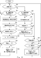
- FIG. 12 is a flowchart showing the flow of control processing according to the second embodiment.
- the information processing device 100 determines whether or not the doors of the vehicle V are locked (S50).
- the information processing device 100 may determine whether or not the doors of the vehicle V are locked by monitoring the state of the first driving section 130 in the first vehicle control section 104, for example.
- the acquisition unit 102 determines whether or not the first captured image acquisition condition described above is satisfied (S51). If the first captured image acquisition condition is not satisfied (No in S51), the acquisition unit 102 returns the process to step S50.
- the acquisition unit 102 supplies the captured image acquired from the peripheral camera 120 as the first captured image to the first authentication unit 103, and the process proceeds to step S52.
- the first authentication unit 103 transmits a face authentication request via the network N to the face authentication device 2 .
- the first authentication unit 103 includes at least one of the first captured image, the face area extracted from the first captured image, and the facial feature information extracted from the face area in the face authentication request.
- the first authentication unit 103 receives the face authentication result from the face authentication device 2 via the network N (S53).
- the face authentication result includes the fact and the user ID when the face authentication is successful, and includes the fact when the face authentication is unsuccessful.
- the first authentication unit 103 determines whether or not face authentication has succeeded (S54). If face authentication is not successful (No in S54), the first authentication unit 103 returns the process to step S50. On the other hand, if face authentication is successful (Yes in S54), the first authentication unit 103 identifies the user ID for which face authentication is successful (S56), and advances the process to step S57. Specifically, first authentication unit 103 extracts the user ID included in the face authentication result. In step S57, the first authentication unit 103 determines whether or not the specified user ID is included in the user information stored in the storage unit 108, so that the user U who has succeeded in face authentication is a registered user. It is determined whether or not (S57).
- the first authentication unit 103 If the user U who has succeeded in face authentication is not a registered user (No in S57), the first authentication unit 103 returns the process to step S50. On the other hand, if the user U who has succeeded in face authentication is a registered user (Yes in S57), the first vehicle control unit 104 sends the first control signal for unlocking the door of the vehicle V to the first drive unit 130. (S58).
- the acquisition unit 102 determines whether or not the second captured image acquisition condition described above is satisfied (S59). If the second captured image acquisition condition is not satisfied (No in S59), the acquisition unit 102 advances the process to step S63. On the other hand, if the second captured image acquisition condition is satisfied (Yes in S59), the acquisition unit 102 supplies the captured image acquired from the peripheral camera 120 or the in-vehicle camera 122 as the second captured image to the motion determination unit 106, and performs processing. to step S60.
- step S ⁇ b>60 the motion determination unit 106 detects a human region or face region included in the second captured image, and based on the human region or the face region, motion information for authentication of the user U included in the second captured image. is generated (S60). Next, the motion determination unit 106 determines whether or not the motion information for authentication of the user U matches the motion information for registration of the registered motion registered in the motion table, thereby determining whether the motion of the user U is correct. It is determined whether or not it is a registration operation (S61). If the motion of the user U is not a registered motion (No in S61), the motion determination unit 106 advances the process to step S63.
- step S62 the second vehicle control unit 107 generates a second control signal according to the motion of the user U (that is, the matching registered motion), and transmits the second control signal to the second driving unit 140 (S62 ). Specifically, the second vehicle control unit 107 identifies the second controlled object and the second control type corresponding to the registered operation using the operation table, and performs the second control based on the second controlled object and the second control type. Generate control signals. Second vehicle control unit 107 then transmits a second control signal to second drive unit 140 corresponding to the second controlled object. Then, the second vehicle control unit 107 advances the process to step S63.
- step S63 the information processing device 100 determines whether or not the doors of the vehicle V are closed.
- the information processing device 100 may determine whether or not the door of the vehicle V is closed by monitoring the state of the second driving section 140-1 in the second vehicle control section 107, for example. If the door of the vehicle V is not closed, that is, if it is open (No in S63), the information processing device 100 returns the process to step S50. On the other hand, if the door of the vehicle V is closed (Yes in S63), it is determined whether or not a predetermined time ⁇ t has passed since the door was closed (S64). If the predetermined time ⁇ t has not elapsed (No in S64), the process returns to step S50.
- the first vehicle control unit 104 transmits a third control signal for locking the doors of the vehicle V to the first drive unit 130 (S65), and performs processing. is returned to step S50.
- FIG. 13 is a sequence diagram showing an example of the flow of registration processing according to the second embodiment.
- the camera captures an image of the user U (S501), and transmits the captured image to the information processing apparatus 100 as a registered image (S502).
- the camera that captures the user U may be the peripheral camera 120 or the in-vehicle camera 122 .
- a camera (not shown) of the user terminal may photograph the user U, and the user terminal may transmit the photographed image to the information processing apparatus 100 via the network N.
- the information processing apparatus 100 transmits a face information registration request including the registered image to the face authentication apparatus 2 via the network N (S503).
- the face authentication device 2 registers the face information (face feature information) of the user U based on the registration image included in the received face information registration request (S504). Then, the face authentication device 2 notifies the user ID to the information processing device 100 via the network N (S505). The information processing apparatus 100 registers the notified user ID as user information (S506). Then, the information processing apparatus 100 receives an input operation of motion information for registration from the registered user (S507). Then, the information processing apparatus 100 registers, in the operation table, the received operation information for registration, specifically, information that associates the contents of the registered operation with the contents of the second control (S508).
- FIG. 14 is a sequence diagram showing an example of the flow of control processing according to the second embodiment. This figure shows the control process when the user U gets into the vehicle V. As shown in FIG.
- the peripheral camera 120 takes an image of the user U (S521), and transmits the taken image to the information processing apparatus 100 via the network N (S522). Assume that the first captured image acquisition condition is satisfied here. In this case, the captured image received by the information processing apparatus 100 is identified as the first captured image.
- the information processing apparatus 100 transmits a face authentication request for the face area of the user U in the received photographed image to the face authentication apparatus 2 via the network N (S523).
- the face authentication device 2 performs face authentication on the face area of the user U in the first captured image included in the received face authentication request (S524). Here, it is assumed that face authentication has succeeded.
- the face authentication device 2 transmits the fact that the face authentication was successful and the face authentication result including the user ID to the information processing device 100 via the network N (S525).
- the information processing apparatus 100 that has received the face authentication result compares the user ID and user information included in the face authentication result, and determines whether or not the user U included in the first captured image is a registered user ( S526). Subsequently, the information processing device 100 transmits a first control signal for unlocking the doors of the vehicle V as the first control to the first drive unit 130 (S527). As a result, the doors of the vehicle V are unlocked.
- the peripheral camera 120 takes an image of the user U (S528), and transmits the taken image to the information processing apparatus 100 via the network N (S529).
- the captured image received by the information processing apparatus 100 is identified as the second captured image.
- the motion determination unit 106 of the information processing apparatus 100 determines whether or not the motion of the user U included in the second captured image is the registered motion (S530).
- the information processing apparatus 100 refers to the motion table and determines that the motion of the user U matches the motion ID “G1”.
- information processing device 100 transmits a second control signal for opening the door of vehicle V as second control to second drive unit 140-1 (S531). As a result, the door of the vehicle V is opened.
- step S530 the information processing apparatus 100 executes motion determination based on the second captured image.
- the information processing apparatus 100 specifies the first captured image or a frame of a predetermined period including the capturing timing of the first captured image as the second captured image, and performs the action determination based on the second captured image. You may In this case, steps S528-529 may be omitted.
- FIG. 15 is a sequence diagram showing another example of the flow of control processing according to the second embodiment. This figure also shows the control process when the user U gets into the vehicle V.
- processing similar to steps S521 to S527 in FIG. 14 is executed.
- the user U opens the door of the vehicle V and gets into the vehicle V.
- the in-vehicle camera 122 photographs the user U (S532), and transmits the photographed image to the information processing device 100 via the network N (S533).
- the second captured image acquisition condition is satisfied here.
- the captured image received by the information processing apparatus 100 is identified as the second captured image. Then, based on the second captured image, the information processing apparatus 100 determines whether or not the motion of the user U included in the second captured image is the registered motion (S534). Here, it is assumed that the user U performs an action of moving the direction of the line of sight from the bottom to the top. In this case, the information processing apparatus 100 refers to the motion table and determines that the motion of the user U matches the motion ID “G3”. Then, information processing device 100 transmits a second control signal for activating the IG power supply of vehicle V as second control to second drive unit 140-5 (S535). As a result, the IG power source of the vehicle V is activated.
- processing after step S532 may be performed after step S531 in FIG.
- the information processing apparatus 100 executes control for unlocking the doors of the vehicle V by biometric authentication, and performs control other than unlocking of the vehicle V by operation determination. Perform controls that require will.
- the user U can unlock the doors of the vehicle and perform other operations related to the vehicle as intended without using the electronic key.
- the user U can also unlock only. Therefore, the same effects as those of the first embodiment can be obtained, and the convenience of operating the vehicle is improved.
- Embodiment 3 of the present disclosure will be described.
- the third embodiment is characterized in that the content of the registered motion or the content of the second control that is subject to motion determination may vary depending on the position of the user.
- FIG. 16 is a block diagram showing the configuration of the in-vehicle system 1a according to the third embodiment.
- In-vehicle system 1a replaces peripheral camera 120, second driving units 140-1 and 140-5, and information processing device 100 with peripheral cameras 120-1 to 120-5 and second driving units 140-1 to 140-6. , and an information processing device 100a.
- the numbers of the peripheral cameras 120 and the second drive units 140 are not limited to this.
- the peripheral cameras 120-1 to 120-5 are the peripheral cameras 120 mounted at different positions of the vehicle V.
- the peripheral cameras 120-1, 120-2, 120-3, 120-4, and 120-5 are cameras for capturing the scenery of the left front, left side, right front, right side, and rear of the vehicle V, respectively. be.
- Peripheral cameras 120-1 to 120-5 are connected to an acquisition unit 102a, which will be described later.
- the second driving units 140-1, 140-2, 140-3 and 140-4 are actuators that generate driving force for opening and closing various opening/closing bodies of the vehicle V.
- the second drive units 140-1, 140-2, 140-3, and 140-4 are actuators that generate drive forces for opening and closing the doors, bonnet, fuel filler port cover, and trunk cover of the vehicle V, respectively.
- the second driving units 140-5 and 140-6 are switches for starting and stopping various power sources of the vehicle V.
- FIG. As an example, the second drive units 140-5 and 140-6 are switches that activate and deactivate the IG power supply and ACC power supply of the vehicle V, respectively.
- the second drive units 140-1 to 140-6 are connected to a second vehicle control unit 107a, which will be described later.
- the information processing device 100a includes an acquisition unit 102a, a motion determination unit 106a, and a second vehicle control unit 107a instead of the acquisition unit 102, the motion determination unit 106, and the second vehicle control unit 107.
- the acquisition unit 102a has basically the same function as the acquisition unit 102. However, the acquisition unit 102a identifies the second captured image from the captured images acquired from the peripheral cameras 120-1 to 120-5 and the in-vehicle camera 122, and determines the user position, which is the region where the user U is located, included in the second captured image. is different from the acquiring unit 102 in that the . The identification of the user position is performed based on the result of "determining whether or not the user U is positioned in the second captured image acquisition area" in the determination of the second captured image acquisition condition described in the second embodiment. good.
- the second captured image acquisition area which is the second captured image acquisition condition, may differ for each camera.
- FIG. 17 is a diagram illustrating an example of user positions according to the third embodiment;
- the second captured image acquisition areas of peripheral cameras 120-1, 120-2, 120-3, 120-4 and 120-5 are areas A1, A2, B1, B2 and C1, respectively.
- the second captured image acquisition area of the in-vehicle camera 122 is the area D1. Areas A1, A2, B1, B2, C1 and D1 are predetermined with vehicle V as a reference.
- the obtaining unit 102a identifies the second captured image when determining that the user U is positioned in any of the areas A1, A2, B1, B2, C1, and D1, and determines the second captured image and the user position to the motion determining unit 106a. supply to
- the acquiring unit 102a selects, from among the captured images acquired from the peripheral cameras 120-1 to 120-5 and the in-vehicle camera 122, the size, width, or length of the face region of the user U that is equal to or greater than a predetermined number of pixels. is specified as the second captured image. Further, for example, the acquisition unit 102a identifies a captured image in which the length connecting the feature points of predetermined facial features included in the facial region of the user U is equal to or greater than a predetermined number of pixels as the second captured image. Then, the acquisition unit 102a identifies the camera that captured the second captured image, and identifies the second captured image acquisition area corresponding to the camera as the area where the user is located (user position). In the case of this figure, the acquiring unit 102a identifies that the camera that captured the second captured image is the peripheral camera 120-4, and identifies that the user position is the area B2.
- FIG. 18 is a diagram showing another example of user positions according to the third embodiment.
- the second captured image acquisition areas are the area T and the area D1.
- Region T includes regions A1, A2, B1, B2 and C1 corresponding to peripheral cameras 120-1, 120-2, 120-3, 120-4 and 120-5 respectively.
- Areas A1, A2, B1, B2, C1, and D1 in the figure are also predetermined with the vehicle V as a reference.
- the acquisition unit 102a synthesizes captured images acquired from the peripheral cameras 120-1, 120-2, 120-3, 120-4, and 120-5 to generate a bird's-eye view image of the vehicle V viewed from above. do. Then, the acquiring unit 102a detects a person area from the bird's-eye view image, and if the person area is located within the area T, the area including the position of the person area within the area T is specified as the user position.
- an omnidirectional camera may be mounted at a predetermined position of the vehicle V, and the acquisition unit 102a may use an image generated by being photographed by the omnidirectional camera as the overhead image.
- the acquisition unit 102a identifies the camera corresponding to the user position, and identifies the captured image acquired from the camera as the second captured image. Then, the acquisition unit 102a supplies the second captured image and the user position to the motion determination unit 106a. In the case of this figure, acquisition unit 102a specifies that the user position is region B2, and specifies the captured image captured by peripheral camera 120-4 corresponding to region B2 as the second captured image.
- the acquisition unit 102a uses the same method as shown in FIG. 17 to obtain the second captured image and the user.
- the position may be specified and supplied to the motion determination unit 106a.
- the motion determination unit 106a has basically the same function as the motion determination unit 106, but uses a motion table to control motion determination according to the user's position. More specifically, the motion determination unit 106a uses the motion table to determine whether or not the motion of the user U included in the second captured image is a registered motion corresponding to the region where the user U is located. .
- the second vehicle control unit 107a has basically the same function as the second vehicle control unit 107. However, the second vehicle control unit 107a is second in that it transmits the second control signal for executing the second control corresponding to each motion of the person included in the second captured image and the area where the person is located. It differs from the vehicle control unit 107 .
- FIG. 19 is a diagram showing an example of the data structure of the operation table according to the third embodiment.
- the content of the registration operation in the operation table is determined corresponding to each predetermined region with the vehicle V as a reference.
- the contents of the registered actions are the action IDs "G41" and "G42". That is, the motion determination unit 106a determines to which of the motion IDs "G41" and "G42" the motion of the user U corresponds.
- the user position is the area D1
- the contents of the registered actions are the action IDs "G11", “G12", “G21” and “G22”. That is, the motion determination unit 106a determines to which of the motion IDs "G11", “G12", “G21”, and “G22” the motion of the user U corresponds.
- the content of the second control in the operation table is also determined corresponding to each predetermined area with the vehicle V as a reference. For example, when the user position is the area A1 and the user U performs the motion with the motion ID “G11”, the second vehicle control unit 107a executes the second control “open the door”. 2 Send control signals. On the other hand, even if the user U similarly performs the action with the action ID "G11", if the user position is in the region D1, the second vehicle control unit 107a will display the content "activate the ACC power supply”. A second control signal indicating the second control is transmitted.
- FIG. 20 is a flowchart showing an example of the flow of control processing according to the third embodiment.
- the steps shown in FIG. 20 have steps S70-73 instead of steps 60-62 shown in FIG.
- the acquisition unit 102a specifies the camera that captured the second captured image, and specifies the second captured image acquisition area corresponding to the camera as the user position (S70 ). Then, the acquisition unit 102a supplies the second captured image and information on the user position to the motion determination unit 106a. Next, the motion determination unit 106a detects a person area or a face area included in the second captured image, and determines motion information for authentication of the user U included in the second captured image based on the person area or the face area. Generate (S71). Next, the motion determination unit 106a determines whether or not the motion information for authentication of the user U matches the motion information for registration of the registration motion according to the user position, which is registered in the motion table.
- step S72 It is determined whether or not the motion of the user U is a registration motion corresponding to the user position (S72). If the motion of the user U is not a registered motion corresponding to the user position (No in S72), the motion determination unit 106a advances the process to step S63. On the other hand, if the motion of the user U is a registration motion corresponding to the user position (Yes in S72), the motion determination unit 106a advances the process to step S73. In step S73, the second vehicle control unit 107a generates a second control signal according to the motion of the user U (that is, the matching registered motion) and the user position, and transmits the second control signal to the second driving unit 140. (S73).
- the second vehicle control unit 107 uses the operation table to identify the second controlled object and the second control type according to the registered operation and the user position, and based on the second controlled object and the second control type to generate a second control signal. Second vehicle control unit 107 then transmits a second control signal to second drive unit 140 corresponding to the second controlled object. Then, the second vehicle control unit 107a advances the process to step S63.
- the user U can use different actions for operations depending on the position.
- the user U can also vary the content of the second control for each region in which the user U is located. This improves convenience.
- Embodiment 4 is characterized in that the information processing apparatus uses biometric authentication to start action determination when it determines that the person included in the second captured image is a registered user.
- biometric authentication is face authentication also in the present embodiment 4, it is not limited to this.
- FIG. 21 is a block diagram showing the configuration of an in-vehicle system 1b according to the fourth embodiment.
- the in-vehicle system 1b has basically the same configuration and functions as the in-vehicle system 1 according to the second embodiment.
- the in-vehicle system 1b includes an information processing device 100b instead of the information processing device 100.
- FIG. The information processing device 100b basically has the same configuration as the information processing device 100, but has a second authentication unit 105 and a motion determination unit 106b instead of the motion determination unit 106.
- the second authentication unit 105 is also called second authentication means.
- the second authentication unit 105 controls face authentication of the person (user U) included in the second captured image based on the second captured image supplied from the acquisition unit 102, and performs face authentication of the person included in the second captured image. Determine whether U is a registered user. Control of face authentication for user U included in the second captured image by second authentication unit 105 is the same as control of face authentication for user U included in the first captured image by first authentication unit 103 .
- the second authentication unit 105 causes the face authentication device 2 to perform face authentication on the user U included in the second captured image, and based on the face authentication result, the person included in the second captured image is identified. Determine whether or not the user is a registered user. Then, the second authentication unit 105 supplies the registered user determination result to the motion determination unit 106b. Note that processing by the second authentication unit 105 may be referred to as second authentication processing.
- the motion determination unit 106b basically has the same function as the motion determination unit 106. However, the motion determination unit 106b performs motion determination when it is determined that the person included in the second captured image is the registered user.
- FIG. 22 is a flowchart showing an example of the flow of control processing according to the fourth embodiment.
- the steps shown in FIG. 22 have steps S80 to S81 in addition to the steps shown in FIG.
- step S59 the acquisition unit 102 supplies the captured image acquired from the peripheral camera 120 or the in-vehicle camera 122 as the second captured image to the second authentication unit 105, and the process proceeds to step S80.
- step S80 the second authentication unit 105 performs the same processing as that shown in steps S52 to S56 on the second captured image. Then, the second authentication unit 105 determines whether or not the specified user ID is included in the user information stored in the storage unit 108, thereby determining whether the user U who has succeeded in face authentication is a registered user. is determined (S81). If the user U who has succeeded in face authentication is not a registered user (No in S81), the second authentication unit 105 advances the process to step S63.
- step S81 the action determination unit 106b performs the process shown in step S60, and performs the action for authentication of the user U included in the second captured image. Generate information. Steps after step S61 are the same as those in FIG.
- the information processing apparatus 100b does not start motion determination when the biometric authentication based on the second captured image fails. You can avoid running control. Therefore, security can be enhanced. Also, power consumption can be reduced.
- FIG. 23 is a block diagram showing the configuration of an in-vehicle system 1c according to the fifth embodiment.
- the in-vehicle system 1c has basically the same configuration and functions as the in-vehicle system 1b according to the fourth embodiment.
- the in-vehicle system 1c includes a light 150, a speaker 152, and an information processing device 100c instead of the information processing device 100b.
- the light 150 functions as a light output unit that outputs light.
- the speaker 152 functions as an audio output unit that outputs audio.
- the sounds may be warning sounds or action sounds.
- the light 150 and the speaker 152 are an example of a notification unit mounted on the vehicle V that notifies the user U of specific information.
- the lights 150 and speakers 152 may be the lights and speakers that come standard with the vehicle V.
- FIG. The notification unit is connected to the notification control unit 109 and controlled by the notification control unit 109 .
- the notification section may include a display section instead of or in addition to the light 150 .
- the information processing device 100c basically has a notification control unit 109 in addition to the configuration of the information processing device 100b.
- the notification control unit 109 is also called notification control means.
- the notification control unit 109 uses the light 150 and the speaker 152 to notify the start or result of various processes by the information processing device 100c.
- the various processes may be at least one of a first authentication process by the first authentication unit 103, a second authentication process by the second authentication unit 105, or a motion determination process by the motion determination unit 106b.
- the notification control unit 109 may control the light 150 and the speaker 152 so that the notification mode differs according to the type of processing or the start or end of the processing.
- the notification control unit 109 when starting the first authentication process, blinks the light 150 once.
- the case where the first authentication process is started may be the case where the first photographed image acquisition condition is satisfied.
- the notification control unit 109 outputs the operation sound once through the speaker 152 .
- the notification control unit 109 blinks the light 150 twice when starting the second authentication process.
- the case where the second authentication process is started may be the case where the second photographed image acquisition condition is satisfied.
- the notification control unit 109 outputs the operation sound twice from the speaker 152 .
- the notification control unit 109 blinks the light 150 three times when starting the operation determination process. Then, when the motion determination process is completed and the motion of the user U is determined to be the registered motion, the notification control unit 109 outputs the motion sound from the speaker 152 three times.
- the information processing device 100c notifies the user U of the start or result of various processes, so the user U can easily grasp the state of the vehicle V. For example, if the control of the vehicle V is unintentionally executed, it can be dealt with quickly.
- Embodiment 6 is a modification of Embodiment 5, and is characterized in that an information processing apparatus uses a motion determination model learned for each registered user in motion determination processing.
- FIG. 24 is a block diagram showing the overall configuration of a vehicle control system 900d according to the sixth embodiment.
- the vehicle control system 900d includes a management server 3 in addition to the components of the vehicle control system 900 .
- the management server 3 acquires captured images of registered users who are performing registration actions from each in-vehicle system 1 via the network N, and learns an action determination model for each user. As a result, the management server 3 generates a motion determination model that reflects the behavior habits of each user. The management server 3 registers the generated action determination model in the action determination model table T in association with the user ID.
- the motion determination model table T may be stored in a storage unit (not shown) of the management server 3. FIG. Then, the management server 3 transmits the motion determination model associated with the user ID in the motion determination model table T to the in-vehicle system 1 in response to a request from the in-vehicle system 1 .
- the management server 3 associates the learned parameters of the motion determination model with the user ID and registers them in the motion determination model table T. may be transmitted to the in-vehicle system 1.
- the information processing device 100c of the in-vehicle system 1 transmits a motion determination model generation request to the management server 3 via the network N during the initial registration process.
- the action determination model generation request includes the registered user's user ID notified from the face authentication device 2 and the captured image of the registered user who is performing the registration action. Then, the information processing device 100c of the in-vehicle system 1 receives the action determination model corresponding to the registered user from the management server 3 via the network N. Further, when the registered user of the vehicle V is changed and the motion determination model corresponding to the changed registered user has already been generated, the information processing device 100c of the in-vehicle system 1 requests acquisition of the motion determination model. is transmitted to the management server 3 via the network N.
- the motion determination model acquisition request includes the changed user ID of the registered user. Then, the information processing device 100c of the in-vehicle system 1 receives the motion determination model corresponding to the changed registered user from the management server 3 via the network N.
- the information processing device 100c of the in-vehicle system 1 stores the motion determination model received from the management server 3 in the storage unit 108 in association with the user ID of the registered user.
- the motion determination unit 106b performs motion determination using the motion determination model corresponding to the user ID of the registered user.
- FIG. 25 is a diagram showing an example of the data structure of the motion determination model table T according to the sixth embodiment.
- the motion determination model table T associates a user ID with a motion determination model ID that identifies a motion determination model.
- the information processing apparatus 100c controls the motion determination using the motion determination model learned for each registered user, so that the motion determination accuracy can be improved. Also, a motion determination model corresponding to the user ID is stored in the management server 3, and the motion determination model is supplied to the in-vehicle system 1 as needed. Therefore, even when registered users frequently change in rental cars or car sharing, or when user U buys a new vehicle V, a motion determination model corresponding to user U can be easily introduced into in-vehicle system 1 . Therefore, convenience is improved.
- the management server 3 learns a motion determination model for each registered user, but may learn a motion determination model for each user attribute.
- the user attribute may be gender or age.
- the management server 3 may associate the user attributes with the motion determination models and register them in the motion determination model table T.
- the registration unit 101 of the information processing device 100c of the in-vehicle system 1 may register, as user information, information in which the user ID and the user attribute information are associated with each other during the registration process.
- the user attribute information may be obtained by the registration unit 101 via an input unit (not shown) that receives input from the user, or may be obtained by the registration unit 101 via the network N from the user terminal.
- the information processing apparatus 100c receives from the management server 3 the action determination model corresponding to the user attribute corresponding to the user ID of the registered user at the time of initial registration processing or at the time of change of the registered user, and stores it in association with the user ID. It may be stored in unit 108 .
- FIG. 26 is a diagram showing a configuration example of a computer that can be used as the face authentication device 2, the information processing devices 100, 100a, 100b, and 100c, and the management server 3.
- the computer 1000 has a processor 1010 , a storage unit 1020 , a ROM 1030 , a RAM 1040 , a communication interface (IF) 1050 and a user interface 1060 .
- IF communication interface
- the communication interface 1050 is an interface for connecting the computer 1000 and a communication network via wired communication means or wireless communication means.
- User interface 1060 includes a display, such as a display.
- User interface 1060 also includes input units such as a keyboard, mouse, and touch panel.
- the storage unit 1020 is an auxiliary storage device that can hold various data.
- the storage unit 1020 is not necessarily a part of the computer 1000, and may be an external storage device or a cloud storage connected to the computer 1000 via a network.
- the ROM 1030 is a non-volatile storage device. Programs executed by processor 1010 may be stored in storage unit 1020 or ROM 1030 .
- the storage unit 1020 or ROM 1030 stores various programs for implementing the functions of each unit in the face authentication device 2, the information processing devices 100, 100a, 100b, and 100c, and the management server 3, for example.
- the program includes a group of instructions (or software code) that, when read into a computer, cause the computer to perform one or more functions described in the embodiments.
- the program may be stored in a non-transitory computer-readable medium or tangible storage medium.
- computer readable media or tangible storage media may include random-access memory (RAM), read-only memory (ROM), flash memory, solid-state drives (SSD) or other memory technology, CDs -ROM, Digital Versatile Disc (DVD), Blu-ray disc or other optical disc storage, magnetic cassette, magnetic tape, magnetic disc storage or other magnetic storage device.
- the program may be transmitted on a transitory computer-readable medium or communication medium.
- transitory computer readable media or communication media include electrical, optical, acoustic, or other forms of propagated signals.
- the RAM 1040 is a volatile storage device. Various semiconductor memory devices such as DRAM (Dynamic Random Access Memory) or SRAM (Static Random Access Memory) are used for RAM 1040 .
- RAM 1040 can be used as an internal buffer that temporarily stores data and the like.
- the processor 1010 develops the program stored in the memory
- the processor 1010 may be a CPU (Central Processing Unit) or a GPU (Graphics Processing Unit). By the processor 1010 executing the program, the functions of the face authentication device 2, the information processing devices 100, 100a, 100b, and 100c, and the management server 3 can be implemented.
- Processor 1010 may have internal buffers in which data and the like can be temporarily stored.
- the computer is composed of a computer system including a personal computer, a word processor, and the like.
- the computer is not limited to this, and can be configured by a LAN (local area network) server, a computer (personal computer) communication host, a computer system connected to the Internet, or the like. It is also possible to distribute the functions to each device on the network and configure the computer over the entire network.
- Embodiment 2 may be combined with Embodiment 5
- Embodiment 3 may be combined with Embodiment 4 or Embodiment 5.
- the second photographed image is a photographed image generated by photographing the scenery around the vehicle or the interior of the vehicle under predetermined conditions, for example, when the opening/closing member of the vehicle is in the unlocked state. image.
- the acquisition unit 102 acquires the captured image from the peripheral camera 120 or the in-vehicle camera 122 and satisfies the second captured image acquisition condition. is supplied to the motion determination unit 106 as the second captured image.
- the second captured image may also include a captured image generated by capturing the interior of the vehicle when the opening/closing member of the vehicle is in the locked state.
- the acquisition unit 102 operates as the second captured image that is acquired from the in-vehicle camera 122 and that satisfies the second captured image acquisition condition. You may supply to the determination part 106. FIG.
- the face authentication device 2 is connected to the information processing device via the network N, but the functions of the face authentication device 2 are included in the information processing device, It may be connected to various components of the information processing device via a bus.
- biometric authentication of a person included in the first captured image is controlled based on a first captured image generated by capturing scenery around the vehicle, and the person included in the first captured image is a registered user; a first authentication means for determining whether there is First vehicle control for transmitting a first control signal for executing a first control related to unlocking of an opening/closing member of the vehicle when it is determined that the person included in the first captured image is the registered user.
- the information processing apparatus according to appendix 1 or 2, wherein the registration operation is determined based on at least one of a person's line-of-sight direction and face direction.
- Appendix 4 The information processing apparatus according to appendix 3, wherein the second control signal is a control signal for opening and closing the predetermined opening/closing body of the vehicle in a direction corresponding to the direction of the line of sight or the direction of the face.
- Appendix 5 5.
- the information processing apparatus according to any one of additional notes 1 to 4, further comprising notification control means for notifying the start or result of the process by the first authentication means or the process by the action determination means.
- the motion determination unit according to any one of supplementary notes 1 to 7, wherein the motion determination means controls the motion determination when the person included in the second captured image is located in a predetermined area with the vehicle as a reference. information processing equipment. (Appendix 9) The motion determination means determines whether the size or length of the person's face area included in the second captured image is equal to or greater than a predetermined number of pixels, or when the person's face area included in the second captured image has a predetermined number of pixels included in the person's face area. 9. The information processing apparatus according to any one of appendices 1 to 8, wherein the motion determination is controlled when a length connecting the facial features of is equal to or greater than a predetermined number of pixels.
- the registration operation is determined corresponding to each predetermined region based on the vehicle, 10.
- the motion determination unit according to any one of supplementary notes 1 to 9, wherein the motion determination means determines whether or not the motion of the person included in the second captured image is a registered motion corresponding to an area in which the person is located.
- Information processing equipment (Appendix 11)
- the second control is determined corresponding to each motion of a person and each predetermined region based on the vehicle,
- the second vehicle control means transmits a second control signal for executing a second control corresponding to the movement of the person included in the second captured image and the area where the person is located.
- the information processing device according to any one of . (Appendix 12) 12.
- the information processing apparatus according to any one of appendices 1 to 11, further comprising registration means for registering the registration action based on an input from the registered user. (Appendix 13) 13.
- the information processing apparatus according to any one of appendices 1 to 12, wherein the motion determination means controls the motion determination using a motion determination model learned for each registered user.
- a biometric authentication device that performs biometric authentication; comprising an information processing device and The information processing device is causing the biometric authentication device to perform biometric authentication of a person included in the first captured image based on the first captured image generated by capturing the scenery around the vehicle; a first authentication means for determining whether a person is a registered user; First vehicle control for transmitting a first control signal for executing a first control related to unlocking of an opening/closing member of the vehicle when it is determined that the person included in the first captured image is the registered user. means and Based on a second photographed image generated by photographing the scenery around the vehicle or the interior of the vehicle, motion determination is controlled as to whether or not the motion of the person included in the second photographed image is a registered motion.
- a vehicle control system comprising: second vehicle control means for transmitting a second control signal for executing a second control different from the control.
- the information processing device is second authentication for controlling biometric authentication of a person included in the second captured image based on the second captured image and determining whether or not the person included in the second captured image is the registered user; have the means to 15.
- (Appendix 16) further comprising a management server that stores the motion judgment model learned for each registered user, 16.
- the vehicle control system according to appendix 15, wherein the motion determination means controls the motion determination using a motion determination model corresponding to a registered user obtained from the management server.
- biometric authentication of a person included in the first captured image is controlled based on a first captured image generated by capturing scenery around the vehicle, and the person included in the first captured image is a registered user;
- a first authentication stage for determining whether there is First vehicle control for transmitting a first control signal for executing a first control related to unlocking of an opening/closing member of the vehicle when it is determined that the person included in the first captured image is the registered user.
- motion determination is controlled as to whether or not the motion of the person included in the second photographed image is a registered motion.
- a motion determination step to When the action of the person included in the second captured image is the registered action, second control according to the action of the person on a predetermined opening/closing body of the vehicle or the power source of the vehicle, A second vehicle control stage for transmitting a second control signal for performing a second control different from the control.
- biometric authentication of a person included in the first captured image is controlled based on a first captured image generated by capturing a landscape around the vehicle, and the person included in the first captured image is a registered user;
- a first authentication stage for determining whether there is First vehicle control for transmitting a first control signal for executing a first control related to unlocking of an opening/closing member of the vehicle when it is determined that the person included in the first captured image is the registered user.
- a motion determination step to When the action of the person included in the second captured image is the registered action, second control according to the action of the person on a predetermined opening/closing member of the vehicle or the power source of the vehicle, a second vehicle control step of transmitting a second control signal for executing a second control different from the control;
Landscapes
- Engineering & Computer Science (AREA)
- Physics & Mathematics (AREA)
- General Physics & Mathematics (AREA)
- Theoretical Computer Science (AREA)
- Human Computer Interaction (AREA)
- General Engineering & Computer Science (AREA)
- Multimedia (AREA)
- Mechanical Engineering (AREA)
- Health & Medical Sciences (AREA)
- General Health & Medical Sciences (AREA)
- Oral & Maxillofacial Surgery (AREA)
- Computer Vision & Pattern Recognition (AREA)
- Psychiatry (AREA)
- Social Psychology (AREA)
- Lock And Its Accessories (AREA)
Abstract
Description
ここで、改めて実施形態の課題について説明する。
近年、スマートキー等の電子鍵を用いて、車両のドアを非接触で解錠することが行われている。しかし、電子鍵が盗難されると車両のドアの解錠をすることができないという問題があった。また最近では、リレーアタックによる車両の盗難事件が深刻化している。
尚、ドアの開閉操作に限らず、ユーザの意思を必要とするその他の操作も同様である。
まず、本開示の実施形態1について説明する。図1は、実施形態1にかかる情報処理装置10の構成を示すブロック図である。情報処理装置10は、車両の開閉体の解錠制御と、その他の車両に関する各種制御とを実行するためのコンピュータである。情報処理装置10は、車両の周辺の風景を撮影して生成された撮影画像又は車両の室内を撮影して生成された撮影画像を取得し、取得した撮影画像に基づいて、上述した制御を実行する。所定の条件下で車両の周辺の風景を撮影して生成された撮影画像を、第1撮影画像と呼ぶ。例えば、第1撮影画像は、車両の開閉体が施錠状態である場合に、車両の周辺の風景を撮影して生成された撮影画像である。また、所定の条件下で、車両の周辺の風景又は車両の室内を撮影して生成された撮影画像を、第2撮影画像と呼ぶ。例えば、第2撮影画像は、車両の開閉体が解錠状態である場合に、車両の周辺の風景を撮影して生成された撮影画像である。
情報処理装置10は、第1認証部13と、第1車両制御部14と、動作判定部16と、第2車両制御部17とを備える。
次に、本開示の実施形態2について説明する。図3は、実施形態2にかかる車両制御システム900の全体構成を示すブロック図である。車両制御システム900は、生体認証を用いた車両に関する各種制御を実現するためのコンピュータシステムである。車両に関する各種制御とは、車両の開閉体の解錠又は施錠にかかる制御、並びにユーザの意思を必要とするその他の制御である。開閉体は、フロントドア、リアドア、ボンネット、給油口カバー、ドアガラス(窓)、及びトランクカバー等であってよい。ここで、車両の開閉体の解錠にかかる制御を第1制御と呼び、車両の開閉体の施錠にかかる制御を第3制御と呼び、ユーザの意思を必要とするその他の制御を、第2制御と呼ぶ。第2制御は、例えば、車両の開閉体の開放又は閉鎖にかかる制御であってもよいし、車両の電源を起動又は停止することであってよい。車両の電源は、イグニッション電源(IG電源)であってもよいし、アクセサリー電源(ACC電源)であってもよい。
図10は、実施形態2にかかる動作テーブルのデータ構造の一例を示す図である。動作テーブルは、登録動作の内容と、第2制御の内容とを対応付ける。
この場合、取得部102は、車両Vのドアが施錠状態であり、かつ所定の第1撮影画像取得条件を満たした場合、周辺カメラ120から取得した撮影画像を、第1撮影画像として、第1認証部103に供給してよい。第1撮影画像取得条件は、第1認証開始条件とも呼ばれてよい。第1撮影画像取得条件は、周辺カメラ120が撮影した撮影画像に含まれるユーザUが車両Vを基準とする予め定められる領域(第1撮影画像取得領域)に位置することであってよい。例えば、ユーザUが第1撮影画像取得領域に位置するか否かは、周辺カメラ120が撮影した撮影画像に含まれるユーザUの顔領域の大きさ又は幅若しくは長さが所定画素数以上であるか否かにより判定されてよい。また例えば、ユーザUが第1撮影画像取得領域に位置するか否かは、周辺カメラ120が撮影した撮影画像に含まれる、ユーザUの顔領域に含まれる所定の顔器官の特徴点を結ぶ長さが、所定画素数以上であるか否かにより判定されてもよい。顔器官の特徴点は、右目、左目、鼻の端点、口の端点、右眉の端点、及び左眉の端点うち少なくとも2つであってよい。一例として、顔器官の特徴点は、右目と左目である。また例えば、ユーザUが第1撮影画像取得領域に位置するか否かは、車両Vに搭載された複数の車載カメラの撮影画像を合成して得られた俯瞰画像から人物領域を検出し、人物領域の位置に基づいて判定されてもよい。また例えば、ユーザUが第1撮影画像取得領域に位置するか否かは、測距センサ等のセンサが第1撮影画像取得領域における人物の存在を検知したか否かにより判定されてもよい。このように第1撮影画像取得条件を満たすまでは第1認証部103による処理を開始しないことで、消費電力を低減することができる。
次に、本開示の実施形態3について説明する。実施形態3は、ユーザの位置により、動作判定対象となる登録動作の内容又は第2制御の内容が異なり得ることに特徴を有する。
第2駆動部140-1~140-6は、後述する第2車両制御部107aに接続されている。
次に、本開示の実施形態4について説明する。実施形態4は、情報処理装置が、生体認証を利用して、第2撮影画像に含まれる人物が登録ユーザであると判定した場合に動作判定を開始することに特徴を有する。尚、本実施形態4でも、生体認証は顔認証であるが、これに限らない。
次に、本開示の実施形態5について説明する。図23は、実施形態5にかかる車載システム1cの構成を示すブロック図である。車載システム1cは、実施形態4にかかる車載システム1bと基本的に同様の構成及び機能を有する。ただし車載システム1cは、ライト150と、スピーカ152と、情報処理装置100bに代えて情報処理装置100cとを備える。
次に、本開示の実施形態6について説明する。実施形態6は、実施形態5の変形例であり、情報処理装置が、動作判定処理において、登録ユーザ毎に学習した動作判定モデルを用いることに特徴を有する。
(付記1)
車両の周辺の風景を撮影して生成された第1撮影画像に基づいて、前記第1撮影画像に含まれる人物についての生体認証を制御し、前記第1撮影画像に含まれる人物が登録ユーザであるか否かを判定する第1認証手段と、
前記第1撮影画像に含まれる人物が前記登録ユーザであると判定された場合、前記車両の開閉体の解錠に関わる第1制御を実行するための第1制御信号を送信する第1車両制御手段と、
前記車両の周辺の風景又は前記車両の室内を撮影して生成された第2撮影画像に基づいて、前記第2撮影画像に含まれる人物の動作が登録動作であるか否かの動作判定を制御する動作判定手段と、
前記第2撮影画像に含まれる人物の動作が前記登録動作である場合、前記車両の所定の開閉体又は前記車両の電源に対する、前記人物の動作に応じた第2制御であって、前記第1制御とは異なる第2制御を実行するための第2制御信号を送信する第2車両制御手段と
を備える情報処理装置。
(付記2)
前記動作判定手段は、前記車両の前記開閉体が解錠状態である場合、前記第2撮影画像に基づいて、前記動作判定を制御する
付記1に記載の情報処理装置。
(付記3)
前記登録動作は、人物の視線の向き及び顔の向きの少なくとも一方に基づいて定められる、付記1又は2に記載の情報処理装置。
(付記4)
前記第2制御信号は、前記視線の向き又は前記顔の向きに応じた方向に、前記車両の前記所定の開閉体を開閉させるための制御信号である、付記3に記載の情報処理装置。
(付記5)
前記第1認証手段による処理又は前記動作判定手段による処理の、開始又は結果を報知する報知制御手段をさらに備える、付記1から4のいずれか一項に記載の情報処理装置。
(付記6)
前記報知制御手段は、前記車両に搭載されたスピーカ又はライトを用いて、前記開始又は結果を報知する、付記5に記載の情報処理装置。
(付記7)
前記第2撮影画像に基づいて、前記第2撮影画像に含まれる人物についての生体認証を制御し、前記第2撮影画像に含まれる人物が前記登録ユーザであるか否かを判定する第2認証手段を備え、
前記動作判定手段は、前記第2撮影画像に含まれる人物が前記登録ユーザであると判定された場合、前記動作判定を制御する
付記1から6のいずれか一項に記載の情報処理装置。
(付記8)
前記動作判定手段は、前記第2撮影画像に含まれる人物が、前記車両を基準とする予め定められた領域に位置する場合、前記動作判定を制御する
付記1から7のいずれか一項に記載の情報処理装置。
(付記9)
前記動作判定手段は、前記第2撮影画像に含まれる人物の顔領域の大きさ又は長さが所定画素数以上である場合、又は前記第2撮影画像に含まれる人物の顔領域に含まれる所定の顔器官を結ぶ長さが所定画素数以上である場合、前記動作判定を制御する
付記1から8のいずれか一項に記載の情報処理装置。
(付記10)
前記登録動作は、前記車両を基準とする予め定められた各領域に対応して定められ、
前記動作判定手段は、前記第2撮影画像に含まれる人物の動作が、前記人物が位置する領域に対応する登録動作であるか否かを判定する
付記1から9のいずれか一項に記載の情報処理装置。
(付記11)
前記第2制御は、人物の各動作と、前記車両を基準とする予め定められた各領域と、に対応して定められ、
前記第2車両制御手段は、前記第2撮影画像に含まれる人物の動作と、前記人物が位置する領域とに対応する第2制御を実行するための第2制御信号を送信する
付記1から10のいずれか一項に記載の情報処理装置。
(付記12)
前記登録ユーザからの入力に基づいて前記登録動作を登録する登録手段を備える
付記1から11のいずれか一項に記載の情報処理装置。
(付記13)
前記動作判定手段は、登録ユーザ毎に学習した動作判定モデルを用いて、前記動作判定を制御する、付記1から12のいずれか一項に記載の情報処理装置。
(付記14)
生体認証を実行する生体認証装置と、
情報処理装置と
を備え、
前記情報処理装置は、
前記生体認証装置に、車両の周辺の風景を撮影して生成された第1撮影画像に基づく、前記第1撮影画像に含まれる人物についての生体認証を実行させ、前記第1撮影画像に含まれる人物が登録ユーザであるか否かを判定する第1認証手段と、
前記第1撮影画像に含まれる人物が前記登録ユーザであると判定された場合、前記車両の開閉体の解錠に関わる第1制御を実行するための第1制御信号を送信する第1車両制御手段と、
前記車両の周辺の風景又は前記車両の室内を撮影して生成された第2撮影画像に基づいて、前記第2撮影画像に含まれる人物の動作が登録動作であるか否かの動作判定を制御する動作判定手段と、
前記第2撮影画像に含まれる人物の動作が前記登録動作である場合、前記車両の所定の開閉体又は前記車両の電源に対する、前記人物の動作に応じた第2制御であって、前記第1制御とは異なる第2制御を実行するための第2制御信号を送信する第2車両制御手段と
を有する車両制御システム。
(付記15)
前記情報処理装置は、
前記第2撮影画像に基づいて、前記第2撮影画像に含まれる人物についての生体認証を制御し、前記第2撮影画像に含まれる人物が前記登録ユーザであるか否かを判定する第2認証手段を備え、
前記動作判定手段は、前記第2撮影画像に含まれる人物が前記登録ユーザであると判定された場合、前記動作判定を制御する
付記14に記載の車両制御システム。
(付記16)
登録ユーザ毎に学習した動作判定モデルを格納する管理サーバをさらに備え、
前記動作判定手段は、前記管理サーバから取得した登録ユーザに対応する動作判定モデルを用いて、前記動作判定を制御する
付記15に記載の車両制御システム。
(付記17)
車両の周辺の風景を撮影して生成された第1撮影画像に基づいて、前記第1撮影画像に含まれる人物についての生体認証を制御し、前記第1撮影画像に含まれる人物が登録ユーザであるか否かを判定する第1認証段階と、
前記第1撮影画像に含まれる人物が前記登録ユーザであると判定された場合、前記車両の開閉体の解錠に関わる第1制御を実行するための第1制御信号を送信する第1車両制御段階と、
前記車両の周辺の風景又は前記車両の室内を撮影して生成された第2撮影画像に基づいて、前記第2撮影画像に含まれる人物の動作が登録動作であるか否かの動作判定を制御する動作判定段階と、
前記第2撮影画像に含まれる人物の動作が前記登録動作である場合、前記車両の所定の開閉体又は前記車両の電源に対する、前記人物の動作に応じた第2制御であって、前記第1制御とは異なる第2制御を実行するための第2制御信号を送信する第2車両制御段階と
を備える情報処理方法。
(付記18)
コンピュータに、
車両の周辺の風景を撮影して生成された第1撮影画像に基づいて、前記第1撮影画像に含まれる人物についての生体認証を制御し、前記第1撮影画像に含まれる人物が登録ユーザであるか否かを判定する第1認証段階と、
前記第1撮影画像に含まれる人物が前記登録ユーザであると判定された場合、前記車両の開閉体の解錠に関わる第1制御を実行するための第1制御信号を送信する第1車両制御段階と、
前記車両の周辺の風景又は前記車両の室内を撮影して生成された第2撮影画像に基づいて、前記第2撮影画像に含まれる人物の動作が登録動作であるか否かの動作判定を制御する動作判定段階と、
前記第2撮影画像に含まれる人物の動作が前記登録動作である場合、前記車両の所定の開閉体又は前記車両の電源に対する、前記人物の動作に応じた第2制御であって、前記第1制御とは異なる第2制御を実行するための第2制御信号を送信する第2車両制御段階と
を実行させるためのプログラムが格納された非一時的なコンピュータ可読媒体。
2 顔認証装置
3 管理サーバ
10,100,100a,100b,100c 情報処理システム(情報処理装置)
13,103 第1認証部
14,104 第1車両制御部
16,106,106a,106b 動作判定部
17,107,107a 第2車両制御部
101 登録部
102,102a 取得部
105 第2認証部
108 記憶部
109 報知制御部
120 周辺カメラ
122 車内カメラ
130 第1駆動部
140 第2駆動部
150 ライト
152 スピーカ
210 顔情報DB
211 ユーザID
212 顔特徴情報
220 検出部
230 特徴点抽出部
240 登録部
250 認証部
900,900d 車両制御システム
1000 コンピュータ
1010 プロセッサ
1020 記憶部
1030 ROM
1040 RAM
1050 通信インタフェース
1060 ユーザインタフェース
V 車両
U ユーザ
N ネットワーク
A 領域
B 領域
T 動作判定モデルテーブル
Claims (18)
- 車両の周辺の風景を撮影して生成された第1撮影画像に基づいて、前記第1撮影画像に含まれる人物についての生体認証を制御し、前記第1撮影画像に含まれる人物が登録ユーザであるか否かを判定する第1認証手段と、
前記第1撮影画像に含まれる人物が前記登録ユーザであると判定された場合、前記車両の開閉体の解錠に関わる第1制御を実行するための第1制御信号を送信する第1車両制御手段と、
前記車両の周辺の風景又は前記車両の室内を撮影して生成された第2撮影画像に基づいて、前記第2撮影画像に含まれる人物の動作が登録動作であるか否かの動作判定を制御する動作判定手段と、
前記第2撮影画像に含まれる人物の動作が前記登録動作である場合、前記車両の所定の開閉体又は前記車両の電源に対する、前記人物の動作に応じた第2制御であって、前記第1制御とは異なる第2制御を実行するための第2制御信号を送信する第2車両制御手段と
を備える情報処理装置。 - 前記動作判定手段は、前記車両の前記開閉体が解錠状態である場合、前記第2撮影画像に基づいて、前記動作判定を制御する
請求項1に記載の情報処理装置。 - 前記登録動作は、人物の視線の向き及び顔の向きの少なくとも一方に基づいて定められる、請求項1又は2に記載の情報処理装置。
- 前記第2制御信号は、前記視線の向き又は前記顔の向きに応じた方向に、前記車両の前記所定の開閉体を開閉させるための制御信号である、請求項3に記載の情報処理装置。
- 前記第1認証手段による処理又は前記動作判定手段による処理の、開始又は結果を報知する報知制御手段をさらに備える、請求項1から4のいずれか一項に記載の情報処理装置。
- 前記報知制御手段は、前記車両に搭載されたスピーカ又はライトを用いて、前記開始又は結果を報知する、請求項5に記載の情報処理装置。
- 前記第2撮影画像に基づいて、前記第2撮影画像に含まれる人物についての生体認証を制御し、前記第2撮影画像に含まれる人物が前記登録ユーザであるか否かを判定する第2認証手段を備え、
前記動作判定手段は、前記第2撮影画像に含まれる人物が前記登録ユーザであると判定された場合、前記動作判定を制御する
請求項1から6のいずれか一項に記載の情報処理装置。 - 前記動作判定手段は、前記第2撮影画像に含まれる人物が、前記車両を基準とする予め定められた領域に位置する場合、前記動作判定を制御する
請求項1から7のいずれか一項に記載の情報処理装置。 - 前記動作判定手段は、前記第2撮影画像に含まれる人物の顔領域の大きさ又は長さが所定画素数以上である場合、又は前記第2撮影画像に含まれる人物の顔領域に含まれる所定の顔器官を結ぶ長さが所定画素数以上である場合、前記動作判定を制御する
請求項1から8のいずれか一項に記載の情報処理装置。 - 前記登録動作は、前記車両を基準とする予め定められた各領域に対応して定められ、
前記動作判定手段は、前記第2撮影画像に含まれる人物の動作が、前記人物が位置する領域に対応する登録動作であるか否かを判定する
請求項1から9のいずれか一項に記載の情報処理装置。 - 前記第2制御は、人物の各動作と、前記車両を基準とする予め定められた各領域と、に対応して定められ、
前記第2車両制御手段は、前記第2撮影画像に含まれる人物の動作と、前記人物が位置する領域とに対応する第2制御を実行するための第2制御信号を送信する
請求項1から10のいずれか一項に記載の情報処理装置。 - 前記登録ユーザからの入力に基づいて前記登録動作を登録する登録手段を備える
請求項1から11のいずれか一項に記載の情報処理装置。 - 前記動作判定手段は、登録ユーザ毎に学習した動作判定モデルを用いて、前記動作判定を制御する、請求項1から12のいずれか一項に記載の情報処理装置。
- 生体認証を実行する生体認証装置と、
情報処理装置と
を備え、
前記情報処理装置は、
前記生体認証装置に、車両の周辺の風景を撮影して生成された第1撮影画像に基づく、前記第1撮影画像に含まれる人物についての生体認証を実行させ、前記第1撮影画像に含まれる人物が登録ユーザであるか否かを判定する第1認証手段と、
前記第1撮影画像に含まれる人物が前記登録ユーザであると判定された場合、前記車両の開閉体の解錠に関わる第1制御を実行するための第1制御信号を送信する第1車両制御手段と、
前記車両の周辺の風景又は前記車両の室内を撮影して生成された第2撮影画像に基づいて、前記第2撮影画像に含まれる人物の動作が登録動作であるか否かの動作判定を制御する動作判定手段と、
前記第2撮影画像に含まれる人物の動作が前記登録動作である場合、前記車両の所定の開閉体又は前記車両の電源に対する、前記人物の動作に応じた第2制御であって、前記第1制御とは異なる第2制御を実行するための第2制御信号を送信する第2車両制御手段と
を有する車両制御システム。 - 前記情報処理装置は、
前記第2撮影画像に基づいて、前記第2撮影画像に含まれる人物についての生体認証を制御し、前記第2撮影画像に含まれる人物が前記登録ユーザであるか否かを判定する第2認証手段を備え、
前記動作判定手段は、前記第2撮影画像に含まれる人物が前記登録ユーザであると判定された場合、前記動作判定を制御する
請求項14に記載の車両制御システム。 - 登録ユーザ毎に学習した動作判定モデルを格納する管理サーバをさらに備え、
前記動作判定手段は、前記管理サーバから取得した登録ユーザに対応する動作判定モデルを用いて、前記動作判定を制御する
請求項15に記載の車両制御システム。 - 車両の周辺の風景を撮影して生成された第1撮影画像に基づいて、前記第1撮影画像に含まれる人物についての生体認証を制御し、前記第1撮影画像に含まれる人物が登録ユーザであるか否かを判定する第1認証段階と、
前記第1撮影画像に含まれる人物が前記登録ユーザであると判定された場合、前記車両の開閉体の解錠に関わる第1制御を実行するための第1制御信号を送信する第1車両制御段階と、
前記車両の周辺の風景又は前記車両の室内を撮影して生成された第2撮影画像に基づいて、前記第2撮影画像に含まれる人物の動作が登録動作であるか否かの動作判定を制御する動作判定段階と、
前記第2撮影画像に含まれる人物の動作が前記登録動作である場合、前記車両の所定の開閉体又は前記車両の電源に対する、前記人物の動作に応じた第2制御であって、前記第1制御とは異なる第2制御を実行するための第2制御信号を送信する第2車両制御段階と
を備える情報処理方法。 - コンピュータに、
車両の周辺の風景を撮影して生成された第1撮影画像に基づいて、前記第1撮影画像に含まれる人物についての生体認証を制御し、前記第1撮影画像に含まれる人物が登録ユーザであるか否かを判定する第1認証段階と、
前記第1撮影画像に含まれる人物が前記登録ユーザであると判定された場合、前記車両の開閉体の解錠に関わる第1制御を実行するための第1制御信号を送信する第1車両制御段階と、
前記車両の周辺の風景又は前記車両の室内を撮影して生成された第2撮影画像に基づいて、前記第2撮影画像に含まれる人物の動作が登録動作であるか否かの動作判定を制御する動作判定段階と、
前記第2撮影画像に含まれる人物の動作が前記登録動作である場合、前記車両の所定の開閉体又は前記車両の電源に対する、前記人物の動作に応じた第2制御であって、前記第1制御とは異なる第2制御を実行するための第2制御信号を送信する第2車両制御段階と
を実行させるためのプログラムが格納された非一時的なコンピュータ可読媒体。
Priority Applications (5)
| Application Number | Priority Date | Filing Date | Title |
|---|---|---|---|
| PCT/JP2021/015971 WO2022224332A1 (ja) | 2021-04-20 | 2021-04-20 | 情報処理装置、車両制御システム、情報処理方法、及び非一時的なコンピュータ可読媒体 |
| US18/287,361 US12461598B2 (en) | 2021-04-20 | 2021-04-20 | Information processing apparatus, vehicle controlling system, information processing method, and non-transitory computer-readable medium |
| JP2023515913A JP7670124B2 (ja) | 2021-04-20 | 2021-04-20 | 情報処理装置、車両制御システム、情報処理方法、及びプログラム |
| EP21937830.4A EP4310280A4 (en) | 2021-04-20 | 2021-04-20 | Information processing device, vehicle control system, information processing method, and non-transitory computer-readable medium |
| US19/347,978 US20260029856A1 (en) | 2021-04-20 | 2025-10-02 | Information processing apparatus, vehicle controlling system, information processing method, and non-transitory computer-readable medium |
Applications Claiming Priority (1)
| Application Number | Priority Date | Filing Date | Title |
|---|---|---|---|
| PCT/JP2021/015971 WO2022224332A1 (ja) | 2021-04-20 | 2021-04-20 | 情報処理装置、車両制御システム、情報処理方法、及び非一時的なコンピュータ可読媒体 |
Related Child Applications (2)
| Application Number | Title | Priority Date | Filing Date |
|---|---|---|---|
| US18/287,361 A-371-Of-International US12461598B2 (en) | 2021-04-20 | 2021-04-20 | Information processing apparatus, vehicle controlling system, information processing method, and non-transitory computer-readable medium |
| US19/347,978 Continuation US20260029856A1 (en) | 2021-04-20 | 2025-10-02 | Information processing apparatus, vehicle controlling system, information processing method, and non-transitory computer-readable medium |
Publications (1)
| Publication Number | Publication Date |
|---|---|
| WO2022224332A1 true WO2022224332A1 (ja) | 2022-10-27 |
Family
ID=83722024
Family Applications (1)
| Application Number | Title | Priority Date | Filing Date |
|---|---|---|---|
| PCT/JP2021/015971 Ceased WO2022224332A1 (ja) | 2021-04-20 | 2021-04-20 | 情報処理装置、車両制御システム、情報処理方法、及び非一時的なコンピュータ可読媒体 |
Country Status (4)
| Country | Link |
|---|---|
| US (2) | US12461598B2 (ja) |
| EP (1) | EP4310280A4 (ja) |
| JP (1) | JP7670124B2 (ja) |
| WO (1) | WO2022224332A1 (ja) |
Cited By (1)
| Publication number | Priority date | Publication date | Assignee | Title |
|---|---|---|---|---|
| WO2024171434A1 (ja) * | 2023-02-17 | 2024-08-22 | 日本電気株式会社 | 情報更新装置及び方法、認証装置及び方法、並びにコンピュータ可読媒体 |
Families Citing this family (1)
| Publication number | Priority date | Publication date | Assignee | Title |
|---|---|---|---|---|
| US20230090122A1 (en) * | 2020-03-10 | 2023-03-23 | Nec Corporation | Photographing control device, system, method, and non-transitory computer-readable medium storing program |
Citations (8)
| Publication number | Priority date | Publication date | Assignee | Title |
|---|---|---|---|---|
| JP2008002095A (ja) * | 2006-06-20 | 2008-01-10 | Toyota Motor Corp | スマートエントリーシステム |
| JP2011032782A (ja) | 2009-08-04 | 2011-02-17 | Dainippon Printing Co Ltd | キーレスエントリー装置 |
| JP2012172367A (ja) * | 2011-02-21 | 2012-09-10 | Denso Corp | スマートエントリシステム |
| WO2014041955A1 (ja) * | 2012-09-12 | 2014-03-20 | 日産自動車株式会社 | 車両開閉体の制御装置 |
| WO2017163488A1 (ja) * | 2016-03-25 | 2017-09-28 | Necソリューションイノベータ株式会社 | 車両システム |
| JP2020100963A (ja) | 2018-12-20 | 2020-07-02 | 株式会社東海理化電機製作所 | 解錠制御装置、および解錠制御システム |
| US20200291676A1 (en) * | 2019-03-12 | 2020-09-17 | Magna Closures Inc. | Electromagnetic-based sensor with cold mirror cover |
| JP2021001447A (ja) | 2019-06-20 | 2021-01-07 | 株式会社ミツバ | 車両用制御装置 |
Family Cites Families (11)
| Publication number | Priority date | Publication date | Assignee | Title |
|---|---|---|---|---|
| US6498970B2 (en) * | 2001-04-17 | 2002-12-24 | Koninklijke Phillips Electronics N.V. | Automatic access to an automobile via biometrics |
| DE102017200160A1 (de) * | 2017-01-09 | 2018-07-12 | Robert Bosch Gmbh | Verfahren und Vorrichtung zum Überwachen eines abgestellten Kraftfahrzeugs |
| US10173643B2 (en) * | 2017-02-20 | 2019-01-08 | Ford Global Technologies, Llc | Object detection for vehicles |
| EP3585658B1 (en) * | 2017-02-24 | 2024-10-23 | Gentex Corporation | Two factor biometric authentication for auto |
| US10955956B2 (en) * | 2018-05-07 | 2021-03-23 | Apple Inc. | Devices, methods, and graphical user interfaces for interaction with an intensity-sensitive input region |
| WO2020122079A1 (ja) * | 2018-12-11 | 2020-06-18 | ソニー株式会社 | 画像処理装置、画像処理方法および画像処理システム |
| JP7256463B2 (ja) * | 2019-10-11 | 2023-04-12 | トヨタ自動車株式会社 | 車両駐車支援装置 |
| JP7427463B2 (ja) * | 2020-02-12 | 2024-02-05 | 本田技研工業株式会社 | 車両制御装置、車両制御方法、及び車両制御用プログラム |
| EP4107612A4 (en) * | 2020-03-12 | 2024-07-24 | Overhaul Group, Inc. | AUTOMATED MONITORING, DETECTION AND NOTIFICATION OF UNAUTHORIZED MOVEMENT AND/OR THEFT OF VEHICLES AND GOODS |
| JP7419122B2 (ja) * | 2020-03-18 | 2024-01-22 | 本田技研工業株式会社 | 車両制御装置、車両制御方法、及び車両制御用プログラム |
| US11494865B2 (en) * | 2020-04-21 | 2022-11-08 | Micron Technology, Inc. | Passenger screening |
-
2021
- 2021-04-20 EP EP21937830.4A patent/EP4310280A4/en active Pending
- 2021-04-20 US US18/287,361 patent/US12461598B2/en active Active
- 2021-04-20 WO PCT/JP2021/015971 patent/WO2022224332A1/ja not_active Ceased
- 2021-04-20 JP JP2023515913A patent/JP7670124B2/ja active Active
-
2025
- 2025-10-02 US US19/347,978 patent/US20260029856A1/en active Pending
Patent Citations (8)
| Publication number | Priority date | Publication date | Assignee | Title |
|---|---|---|---|---|
| JP2008002095A (ja) * | 2006-06-20 | 2008-01-10 | Toyota Motor Corp | スマートエントリーシステム |
| JP2011032782A (ja) | 2009-08-04 | 2011-02-17 | Dainippon Printing Co Ltd | キーレスエントリー装置 |
| JP2012172367A (ja) * | 2011-02-21 | 2012-09-10 | Denso Corp | スマートエントリシステム |
| WO2014041955A1 (ja) * | 2012-09-12 | 2014-03-20 | 日産自動車株式会社 | 車両開閉体の制御装置 |
| WO2017163488A1 (ja) * | 2016-03-25 | 2017-09-28 | Necソリューションイノベータ株式会社 | 車両システム |
| JP2020100963A (ja) | 2018-12-20 | 2020-07-02 | 株式会社東海理化電機製作所 | 解錠制御装置、および解錠制御システム |
| US20200291676A1 (en) * | 2019-03-12 | 2020-09-17 | Magna Closures Inc. | Electromagnetic-based sensor with cold mirror cover |
| JP2021001447A (ja) | 2019-06-20 | 2021-01-07 | 株式会社ミツバ | 車両用制御装置 |
Non-Patent Citations (1)
| Title |
|---|
| See also references of EP4310280A4 |
Cited By (1)
| Publication number | Priority date | Publication date | Assignee | Title |
|---|---|---|---|---|
| WO2024171434A1 (ja) * | 2023-02-17 | 2024-08-22 | 日本電気株式会社 | 情報更新装置及び方法、認証装置及び方法、並びにコンピュータ可読媒体 |
Also Published As
| Publication number | Publication date |
|---|---|
| JPWO2022224332A1 (ja) | 2022-10-27 |
| US12461598B2 (en) | 2025-11-04 |
| US20240201790A1 (en) | 2024-06-20 |
| EP4310280A1 (en) | 2024-01-24 |
| JP7670124B2 (ja) | 2025-04-30 |
| US20260029856A1 (en) | 2026-01-29 |
| EP4310280A4 (en) | 2024-05-29 |
Similar Documents
| Publication | Publication Date | Title |
|---|---|---|
| CN112622917B (zh) | 用于认证交通工具的乘员的系统和方法 | |
| JP7428993B2 (ja) | 車両のドアロック解除方法及び装置、システム、車両、電子機器並びに記憶媒体 | |
| JP2022118730A (ja) | 車両のドアロック解除方法及び装置、システム、車両、電子機器並びに記憶媒体 | |
| WO2021077738A1 (zh) | 车门控制方法及装置、系统、车、电子设备和存储介质 | |
| CN110297536B (zh) | 一种控制方法及电子设备 | |
| US11358566B2 (en) | In-vehicle complex biometric authentication system and operation method thereof | |
| US20260029856A1 (en) | Information processing apparatus, vehicle controlling system, information processing method, and non-transitory computer-readable medium | |
| JP7427463B2 (ja) | 車両制御装置、車両制御方法、及び車両制御用プログラム | |
| KR20190127338A (ko) | 차량 단말 및 그의 얼굴 인증 방법 | |
| JP7358263B2 (ja) | 車両制御装置、車両制御方法、及び車両制御用プログラム | |
| CN112506353A (zh) | 车辆交互系统、方法、存储介质和车辆 | |
| KR102093858B1 (ko) | 바이오메트릭스 기반 차량 제어 장치 및 이를 이용한 차량 제어 방법 | |
| CN118124516A (zh) | 车辆控制方法、装置及存储介质 | |
| WO2023188083A1 (ja) | 機器制御装置、認証装置、方法、及びコンピュータ可読媒体 | |
| JP7410796B2 (ja) | 車両制御システム、及び車両制御方法 | |
| WO2022264453A1 (ja) | 画像処理装置及び画像処理方法 | |
| US12311882B2 (en) | Vehicle and control method thereof | |
| JP7782669B2 (ja) | 更新通知装置、認証装置、更新通知方法、及びプログラム | |
| JP7310594B2 (ja) | 車両用通信システム | |
| JP7287269B2 (ja) | 車両用通信システム | |
| US20250304008A1 (en) | Entry system and entry control method | |
| US20250305345A1 (en) | Entry system and entry control method | |
| WO2024127449A1 (ja) | 車両ドア制御装置、方法、及びコンピュータ可読媒体 | |
| WO2024116290A1 (ja) | 情報処理システム、情報処理装置、情報処理方法、及び記録媒体 | |
| WO2024121982A1 (ja) | 車両ドア制御装置、方法、及びコンピュータ可読媒体 |
Legal Events
| Date | Code | Title | Description |
|---|---|---|---|
| 121 | Ep: the epo has been informed by wipo that ep was designated in this application |
Ref document number: 21937830 Country of ref document: EP Kind code of ref document: A1 |
|
| WWE | Wipo information: entry into national phase |
Ref document number: 2023515913 Country of ref document: JP |
|
| WWE | Wipo information: entry into national phase |
Ref document number: 18287361 Country of ref document: US |
|
| WWE | Wipo information: entry into national phase |
Ref document number: 2021937830 Country of ref document: EP |
|
| ENP | Entry into the national phase |
Ref document number: 2021937830 Country of ref document: EP Effective date: 20231020 |
|
| NENP | Non-entry into the national phase |
Ref country code: DE |
|
| WWG | Wipo information: grant in national office |
Ref document number: 18287361 Country of ref document: US |