WO2022224436A1 - 空気調和機 - Google Patents
空気調和機 Download PDFInfo
- Publication number
- WO2022224436A1 WO2022224436A1 PCT/JP2021/016441 JP2021016441W WO2022224436A1 WO 2022224436 A1 WO2022224436 A1 WO 2022224436A1 JP 2021016441 W JP2021016441 W JP 2021016441W WO 2022224436 A1 WO2022224436 A1 WO 2022224436A1
- Authority
- WO
- WIPO (PCT)
- Prior art keywords
- heat exchanger
- gas
- refrigerant
- liquid
- flow path
- Prior art date
- Legal status (The legal status is an assumption and is not a legal conclusion. Google has not performed a legal analysis and makes no representation as to the accuracy of the status listed.)
- Ceased
Links
Images










Classifications
-
- F—MECHANICAL ENGINEERING; LIGHTING; HEATING; WEAPONS; BLASTING
- F25—REFRIGERATION OR COOLING; COMBINED HEATING AND REFRIGERATION SYSTEMS; HEAT PUMP SYSTEMS; MANUFACTURE OR STORAGE OF ICE; LIQUEFACTION SOLIDIFICATION OF GASES
- F25B—REFRIGERATION MACHINES, PLANTS OR SYSTEMS; COMBINED HEATING AND REFRIGERATION SYSTEMS; HEAT PUMP SYSTEMS
- F25B13/00—Compression machines, plants or systems, with reversible cycle
-
- F—MECHANICAL ENGINEERING; LIGHTING; HEATING; WEAPONS; BLASTING
- F24—HEATING; RANGES; VENTILATING
- F24F—AIR-CONDITIONING; AIR-HUMIDIFICATION; VENTILATION; USE OF AIR CURRENTS FOR SCREENING
- F24F11/00—Control or safety arrangements
- F24F11/70—Control systems characterised by their outputs; Constructional details thereof
- F24F11/80—Control systems characterised by their outputs; Constructional details thereof for controlling the temperature of the supplied air
- F24F11/83—Control systems characterised by their outputs; Constructional details thereof for controlling the temperature of the supplied air by controlling the supply of heat-exchange fluids to heat-exchangers
-
- F—MECHANICAL ENGINEERING; LIGHTING; HEATING; WEAPONS; BLASTING
- F25—REFRIGERATION OR COOLING; COMBINED HEATING AND REFRIGERATION SYSTEMS; HEAT PUMP SYSTEMS; MANUFACTURE OR STORAGE OF ICE; LIQUEFACTION SOLIDIFICATION OF GASES
- F25B—REFRIGERATION MACHINES, PLANTS OR SYSTEMS; COMBINED HEATING AND REFRIGERATION SYSTEMS; HEAT PUMP SYSTEMS
- F25B39/00—Evaporators; Condensers
- F25B39/02—Evaporators
- F25B39/028—Evaporators having distributing means
-
- F—MECHANICAL ENGINEERING; LIGHTING; HEATING; WEAPONS; BLASTING
- F25—REFRIGERATION OR COOLING; COMBINED HEATING AND REFRIGERATION SYSTEMS; HEAT PUMP SYSTEMS; MANUFACTURE OR STORAGE OF ICE; LIQUEFACTION SOLIDIFICATION OF GASES
- F25B—REFRIGERATION MACHINES, PLANTS OR SYSTEMS; COMBINED HEATING AND REFRIGERATION SYSTEMS; HEAT PUMP SYSTEMS
- F25B39/00—Evaporators; Condensers
- F25B39/04—Condensers
-
- F—MECHANICAL ENGINEERING; LIGHTING; HEATING; WEAPONS; BLASTING
- F25—REFRIGERATION OR COOLING; COMBINED HEATING AND REFRIGERATION SYSTEMS; HEAT PUMP SYSTEMS; MANUFACTURE OR STORAGE OF ICE; LIQUEFACTION SOLIDIFICATION OF GASES
- F25B—REFRIGERATION MACHINES, PLANTS OR SYSTEMS; COMBINED HEATING AND REFRIGERATION SYSTEMS; HEAT PUMP SYSTEMS
- F25B41/00—Fluid-circulation arrangements
- F25B41/40—Fluid line arrangements
- F25B41/42—Arrangements for diverging or converging flows, e.g. branch lines or junctions
-
- F—MECHANICAL ENGINEERING; LIGHTING; HEATING; WEAPONS; BLASTING
- F25—REFRIGERATION OR COOLING; COMBINED HEATING AND REFRIGERATION SYSTEMS; HEAT PUMP SYSTEMS; MANUFACTURE OR STORAGE OF ICE; LIQUEFACTION SOLIDIFICATION OF GASES
- F25B—REFRIGERATION MACHINES, PLANTS OR SYSTEMS; COMBINED HEATING AND REFRIGERATION SYSTEMS; HEAT PUMP SYSTEMS
- F25B5/00—Compression machines, plants or systems, with several evaporator circuits, e.g. for varying refrigerating capacity
- F25B5/02—Compression machines, plants or systems, with several evaporator circuits, e.g. for varying refrigerating capacity arranged in parallel
-
- F—MECHANICAL ENGINEERING; LIGHTING; HEATING; WEAPONS; BLASTING
- F25—REFRIGERATION OR COOLING; COMBINED HEATING AND REFRIGERATION SYSTEMS; HEAT PUMP SYSTEMS; MANUFACTURE OR STORAGE OF ICE; LIQUEFACTION SOLIDIFICATION OF GASES
- F25B—REFRIGERATION MACHINES, PLANTS OR SYSTEMS; COMBINED HEATING AND REFRIGERATION SYSTEMS; HEAT PUMP SYSTEMS
- F25B6/00—Compression machines, plants or systems, with several condenser circuits
- F25B6/02—Compression machines, plants or systems, with several condenser circuits arranged in parallel
-
- F—MECHANICAL ENGINEERING; LIGHTING; HEATING; WEAPONS; BLASTING
- F25—REFRIGERATION OR COOLING; COMBINED HEATING AND REFRIGERATION SYSTEMS; HEAT PUMP SYSTEMS; MANUFACTURE OR STORAGE OF ICE; LIQUEFACTION SOLIDIFICATION OF GASES
- F25B—REFRIGERATION MACHINES, PLANTS OR SYSTEMS; COMBINED HEATING AND REFRIGERATION SYSTEMS; HEAT PUMP SYSTEMS
- F25B2313/00—Compression machines, plants or systems with reversible cycle not otherwise provided for
- F25B2313/023—Compression machines, plants or systems with reversible cycle not otherwise provided for using multiple indoor units
- F25B2313/0233—Compression machines, plants or systems with reversible cycle not otherwise provided for using multiple indoor units in parallel arrangements
-
- F—MECHANICAL ENGINEERING; LIGHTING; HEATING; WEAPONS; BLASTING
- F25—REFRIGERATION OR COOLING; COMBINED HEATING AND REFRIGERATION SYSTEMS; HEAT PUMP SYSTEMS; MANUFACTURE OR STORAGE OF ICE; LIQUEFACTION SOLIDIFICATION OF GASES
- F25B—REFRIGERATION MACHINES, PLANTS OR SYSTEMS; COMBINED HEATING AND REFRIGERATION SYSTEMS; HEAT PUMP SYSTEMS
- F25B2313/00—Compression machines, plants or systems with reversible cycle not otherwise provided for
- F25B2313/025—Compression machines, plants or systems with reversible cycle not otherwise provided for using multiple outdoor units
- F25B2313/0253—Compression machines, plants or systems with reversible cycle not otherwise provided for using multiple outdoor units in parallel arrangements
-
- F—MECHANICAL ENGINEERING; LIGHTING; HEATING; WEAPONS; BLASTING
- F25—REFRIGERATION OR COOLING; COMBINED HEATING AND REFRIGERATION SYSTEMS; HEAT PUMP SYSTEMS; MANUFACTURE OR STORAGE OF ICE; LIQUEFACTION SOLIDIFICATION OF GASES
- F25B—REFRIGERATION MACHINES, PLANTS OR SYSTEMS; COMBINED HEATING AND REFRIGERATION SYSTEMS; HEAT PUMP SYSTEMS
- F25B2313/00—Compression machines, plants or systems with reversible cycle not otherwise provided for
- F25B2313/031—Sensor arrangements
- F25B2313/0313—Pressure sensors near the outdoor heat exchanger
-
- F—MECHANICAL ENGINEERING; LIGHTING; HEATING; WEAPONS; BLASTING
- F25—REFRIGERATION OR COOLING; COMBINED HEATING AND REFRIGERATION SYSTEMS; HEAT PUMP SYSTEMS; MANUFACTURE OR STORAGE OF ICE; LIQUEFACTION SOLIDIFICATION OF GASES
- F25B—REFRIGERATION MACHINES, PLANTS OR SYSTEMS; COMBINED HEATING AND REFRIGERATION SYSTEMS; HEAT PUMP SYSTEMS
- F25B2313/00—Compression machines, plants or systems with reversible cycle not otherwise provided for
- F25B2313/031—Sensor arrangements
- F25B2313/0315—Temperature sensors near the outdoor heat exchanger
-
- F—MECHANICAL ENGINEERING; LIGHTING; HEATING; WEAPONS; BLASTING
- F25—REFRIGERATION OR COOLING; COMBINED HEATING AND REFRIGERATION SYSTEMS; HEAT PUMP SYSTEMS; MANUFACTURE OR STORAGE OF ICE; LIQUEFACTION SOLIDIFICATION OF GASES
- F25B—REFRIGERATION MACHINES, PLANTS OR SYSTEMS; COMBINED HEATING AND REFRIGERATION SYSTEMS; HEAT PUMP SYSTEMS
- F25B2700/00—Sensing or detecting of parameters; Sensors therefor
- F25B2700/19—Pressures
- F25B2700/195—Pressures of the condenser
-
- F—MECHANICAL ENGINEERING; LIGHTING; HEATING; WEAPONS; BLASTING
- F25—REFRIGERATION OR COOLING; COMBINED HEATING AND REFRIGERATION SYSTEMS; HEAT PUMP SYSTEMS; MANUFACTURE OR STORAGE OF ICE; LIQUEFACTION SOLIDIFICATION OF GASES
- F25B—REFRIGERATION MACHINES, PLANTS OR SYSTEMS; COMBINED HEATING AND REFRIGERATION SYSTEMS; HEAT PUMP SYSTEMS
- F25B2700/00—Sensing or detecting of parameters; Sensors therefor
- F25B2700/21—Temperatures
- F25B2700/2116—Temperatures of a condenser
- F25B2700/21162—Temperatures of a condenser of the refrigerant at the inlet of the condenser
-
- F—MECHANICAL ENGINEERING; LIGHTING; HEATING; WEAPONS; BLASTING
- F25—REFRIGERATION OR COOLING; COMBINED HEATING AND REFRIGERATION SYSTEMS; HEAT PUMP SYSTEMS; MANUFACTURE OR STORAGE OF ICE; LIQUEFACTION SOLIDIFICATION OF GASES
- F25B—REFRIGERATION MACHINES, PLANTS OR SYSTEMS; COMBINED HEATING AND REFRIGERATION SYSTEMS; HEAT PUMP SYSTEMS
- F25B2700/00—Sensing or detecting of parameters; Sensors therefor
- F25B2700/21—Temperatures
- F25B2700/2116—Temperatures of a condenser
- F25B2700/21163—Temperatures of a condenser of the refrigerant at the outlet of the condenser
Definitions
- the present disclosure relates to air conditioners.
- a non-azeotropic refrigerant mixture which is a mixture of two or more refrigerants, is used as a refrigerant for refrigeration cycle devices such as air conditioners.
- Patent Documents 1 and 2 are patent documents that disclose refrigeration cycle devices using such a non-azeotropic refrigerant mixture.
- the refrigerant is arranged in the airflow direction of the heat exchanger. It is required to flow as a countercurrent in the opposite direction.
- Patent Document 1 proposes an air conditioner using a hexagonal valve and an expansion valve. Further, Japanese Patent Laying-Open No. 09-196489 (Patent Document 2) proposes an air conditioner to which a bridge circuit using check valves is applied.
- a heat exchanger functions as an evaporator
- the inlet side of the refrigerant in the heat exchanger has a gas-liquid refrigerant.
- a liquid two-phase distributor is arranged.
- an orifice is arranged inside the gas-liquid two-phase distributor in order to evenly distribute the refrigerant in the gas-liquid two-phase state.
- the refrigerant flows in the same direction in the heat exchanger when it functions as a condenser and when it functions as an evaporator. .
- the heat exchanger functions as a condenser, for example, when gas refrigerant flows through a gas-liquid two-phase distributor in which a distributor is arranged, pressure loss increases. Further, when the heat exchanger functions as an evaporator, for example, if the gas refrigerant after heat exchange flows through the gas-liquid two-phase distributor in which the distributor is arranged, the pressure loss increases.
- the present disclosure has been made to solve such technical problems, and the purpose thereof is to provide an air conditioner using a non-azeotropic refrigerant mixture that can reduce pressure loss. be.
- An air conditioner is an air conditioner including a refrigeration cycle circuit including an outdoor unit and an indoor unit in which a non-azeotropic refrigerant mixture circulates, wherein at least one of the outdoor unit and the indoor unit 1 heat exchanger, second heat exchanger, first gas-liquid two-phase distributor, first gas distributor, second gas distributor, second gas-liquid two-phase distributor, first stream and a second flow path.
- the first heat exchanger includes first and second sections connected in series.
- the second heat exchanger includes third and fourth sections connected in series.
- the first gas-liquid two-phase distributor is connected to the first part on the side opposite to the side to which the second part is connected.
- the first gas distributor is connected to the second part on the side opposite to the side to which the first part is connected.
- the second gas distributor is connected to the third part on the side opposite to the side to which the fourth part is connected.
- the second gas-liquid two-phase distributor is connected to the fourth section on the side opposite to the side to which the third section is connected.
- the first flow path includes a portion connecting the first gas distributor, the second section, the first section and the first gas-liquid two-phase distributor in sequence.
- the second flow path includes a portion connecting the second gas distributor, the third section, the fourth section, and the second gas-liquid two-phase distributor in sequence.
- the first flow path in which the first heat exchanger is arranged and the second flow path in which the second heat exchanger is arranged are composed of a first gas-liquid two-phase distributor and a second gas-liquid two-phase distributor.
- the first part is arranged on the windward side
- the second part is arranged on the leeward side
- the third part is arranged on the windward side with respect to the ventilation direction of the air passing through the first heat exchanger and the second heat exchanger, respectively.
- the fourth section is located on the leeward side.
- the gaseous non-azeotropic refrigerant mixture flows into the first gas splitter in the first flow path, and flows into the first gas splitter in the first heat exchanger. , flows through the first gas-liquid two-phase distributor, flows into the second gas splitter in the second flow path, becomes liquid refrigerant in the second heat exchanger, and becomes the second gas-liquid two-phase distributor will flow.
- the gas-liquid two-phase non-azeotropic refrigerant mixture flows into the first gas-liquid two-phase distributor in the first flow path and becomes gaseous refrigerant in the first heat exchanger, It flows through the first gas splitter, flows into the second gas-liquid two-phase distributor in the second flow path, becomes gaseous refrigerant in the second heat exchanger, and flows through the first gas splitter. Become. Thereby, the pressure loss of the non-azeotropic refrigerant mixture circulating in the refrigeration cycle circuit can be reduced.
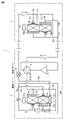
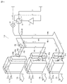
- FIG. 1 is a diagram showing a refrigeration cycle circuit of an air conditioner according to Embodiment 1.
- FIG. FIG. 4 is a perspective view schematically showing the structure of an outdoor heat exchanger and the like in the outdoor unit in the same embodiment.
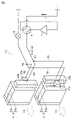
- FIG. 4 is a perspective view for explaining the flow of refrigerant in an outdoor heat exchanger or the like during cooling operation in the same embodiment.
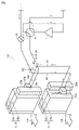
- FIG. 4 is a perspective view for explaining the flow of refrigerant in an outdoor heat exchanger or the like during heating operation in the same embodiment.
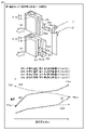
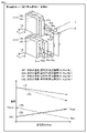
- FIG. 4 is a diagram including a graph regarding the temperature of refrigerant and a graph regarding the temperature of air for explaining the effect of the outdoor heat exchanger and the like during cooling operation in the same embodiment.
- FIG. 4 is a diagram including a graph regarding the temperature of refrigerant and a graph regarding the temperature of air for explaining the effect of the outdoor heat exchanger and the like during heating operation in the same embodiment.
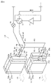
- it is a diagram showing a refrigeration cycle circuit of an air conditioner according to a modification.
- FIG. 7 is a diagram showing a refrigeration cycle circuit of an air conditioner according to Embodiment 2;
- FIG. 4 is a perspective view schematically showing the structure of an outdoor heat exchanger and the like in the outdoor unit in the same embodiment.
- FIG. 4 is a perspective view for explaining the flow of refrigerant in an outdoor heat exchanger or the like during cooling operation in the same embodiment.
- FIG. 4 is a perspective view for explaining the flow of refrigerant in an outdoor heat exchanger or the like during heating operation in the same embodiment.
- FIG. 4 is a diagram including a graph regarding the temperature of refrigerant and a graph regarding the temperature of air for explaining the effect of the outdoor heat exchanger and the like during cooling operation in the same embodiment.
- FIG. 4 is a diagram including a graph regarding the temperature of refrigerant and a graph regarding the temperature of air for explaining the effect of the outdoor heat exchanger and the like during heating operation in the same embodiment.
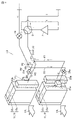
- FIG. 7 is a diagram showing a refrigeration cycle circuit of an air conditioner according to Embodiment 3;
- FIG. 4 is a perspective view schematically showing the structure of an outdoor heat exchanger and the like in the outdoor unit in the same embodiment.
- FIG. 4 is a perspective view for explaining the flow of refrigerant in an outdoor heat exchanger or the like during cooling operation in the same embodiment.
- FIG. 4 is a perspective view for explaining the flow of refrigerant in an outdoor heat exchanger or the like during heating operation in the same embodiment.
- FIG. 4 is a diagram including a graph regarding the temperature of refrigerant and a graph regarding the temperature of air for explaining the effect of the outdoor heat exchanger and the like during cooling operation in the same embodiment.
- FIG. 4 is a diagram including a graph regarding the temperature of refrigerant and a graph regarding the temperature of air for explaining the effect of the outdoor heat exchanger and the like during heating operation in the same embodiment.
- Embodiment 1 An example of an air conditioner according to Embodiment 1 will be described. As shown in FIG. 1 , the air conditioner 1 has an outdoor unit 3 and an indoor unit 5 .
- the outdoor unit 3 accommodates a compressor 7, a four-way valve 9, an outdoor heat exchanger 11, an expansion valve 19, and the like.
- An indoor heat exchanger 27 and the like are accommodated in the indoor unit 5 .
- a refrigeration cycle circuit 51 is configured by connecting the compressor 7, the four-way valve 9, the outdoor heat exchanger 11, the expansion valve 19, and the indoor heat exchanger 27 by refrigerant pipes 41.
- a refrigerant circulates in the refrigeration cycle circuit 51 (refrigerant pipe 41).
- a non-azeotropic mixed refrigerant 43 is used as a refrigerant.
- the non-azeotropic mixed refrigerant 43 is a mixed refrigerant in which a plurality of single components are mixed, and is a refrigerant in which a component difference occurs between the gas phase and the liquid phase.
- the outdoor heat exchanger 11 includes an outdoor first heat exchanger 13 as a first heat exchanger and an outdoor second heat exchanger 15 as a second heat exchanger. ing.
- the outdoor second heat exchanger 15 is arranged on the outdoor first heat exchanger 13 .
- the first outdoor heat exchanger 13 includes a first portion 13a and a second portion 13b.
- the first portion 13a and the second portion 13b are connected in series.
- the first portion 13a and the second portion 13b are arranged along the ventilation direction (see arrow YA).
- the first part 13a is arranged on the windward side.
- the second part 13b is arranged on the leeward side.
- a gas-liquid two-phase distributor 21a as a first gas-liquid two-phase distributor is connected to the first portion 13a on the side opposite to the side to which the second portion 13b is connected.
- a gas distributor 23a as a first gas distributor is connected to the second portion 13b on the side opposite to the side to which the first portion 13a is connected.
- the outdoor second heat exchanger 15 includes a third section 15a and a fourth section 15b.
- the third portion 15a and the fourth portion 15b are connected in series.
- the third portion 15a and the fourth portion 15b are arranged along the ventilation direction (see arrow YA).
- the third part 15a is arranged on the windward side.
- the fourth part 15b is arranged on the leeward side.
- a gas-liquid two-phase distributor 21b as a second gas-liquid two-phase distributor is connected to the fourth portion 15b on the side opposite to the side to which the third portion 15a is connected.
- a gas distributor 23b as a second gas distributor is connected to the third portion 15a on the side opposite to the side to which the fourth portion 15b is connected.
- the air conditioner 1 is provided with a flow path R1 as a first flow path including a portion connecting the gas distributor 23a, the second portion 13b, the first portion 13a, and the gas-liquid two-phase distributor 21a in this order.
- a channel R2 is provided as a second channel, including a portion that connects the gas distributor 23b, the third portion 15a, the fourth portion 15b, and the gas-liquid two-phase distributor 21b in this order.
- the flow path R1 in which the first outdoor heat exchanger 13 is arranged and the flow path R2 in which the second outdoor heat exchanger 15 is arranged are formed by a gas-liquid two-phase distributor 21a and a gas-liquid two-phase distributor 21b. It is connected in parallel with the refrigerating cycle circuit 51 in such a manner that the gas distributor 23a and the gas distributor 23b are connected. That is, the flow path R1 and the flow path R2 are connected in parallel with the refrigeration cycle circuit 51 (main flow path) in which the non-azeotropic refrigerant mixture circulates.
- the indoor heat exchanger 27 includes a first indoor heat exchanger 29 and a second indoor heat exchanger 31 .
- a gas-liquid two-phase distributor 33a is connected to one end of the indoor first heat exchanger 29.
- a gas distributor 35a is connected to the other end of the indoor first heat exchanger 29 .
- a gas-liquid two-phase distributor 33b is connected to one end side of the indoor second heat exchanger 31 .
- a gas distributor 35 b is connected to the other end of the indoor second heat exchanger 31 .
- the air conditioner 1 is provided with a flow path R3 including a portion connecting the gas distributor 35a, the gas-liquid two-phase distributor 33a, and the indoor first heat exchanger 29 in this order. Further, a flow path R4 including a portion connecting the gas distributor 35b, the indoor second heat exchanger 31, and the gas-liquid two-phase distributor 33b in this order is provided.
- the flow path R3 in which the first indoor heat exchanger 29 is arranged and the second indoor heat exchanger 31 in which the second indoor heat exchanger 31 is arranged are divided into a gas-liquid two-phase distributor 33a and a gas-liquid two-phase distributor 33a. 33b, and the gas distributor 35a and the gas distributor 35b are connected in parallel to the refrigerating cycle circuit 51. As shown in FIG. That is, the flow path R3 and the flow path R4 are connected in parallel to the refrigeration cycle circuit 51 (main flow path) in which the non-azeotropic refrigerant mixture circulates.
- the air conditioner 1 according to Embodiment 1 is configured as described above.
- cooling operation First, as the operation of the air conditioner 1 (refrigeration cycle circuit 51), the cooling operation as the first operation mode will be described.
- the outdoor heat exchanger 11 in the outdoor unit 3 functions as a condenser
- the indoor heat exchanger 27 in the indoor unit 5 functions as an evaporator.
- high-temperature and high-pressure gas refrigerant (single-phase) is discharged from the compressor 7.
- the discharged high-temperature and high-pressure gas refrigerant is sent to the outdoor unit 3 via the four-way valve 9 .
- the sent refrigerant flows through the outdoor heat exchanger 11 .
- the refrigerant flows in parallel through the first outdoor heat exchanger 13 (flow path R1) and the second outdoor heat exchanger 15 (flow path R2). The flow of refrigerant in the outdoor heat exchanger 11 will be described in detail later.
- heat exchange takes place between the flowing refrigerant and air supplied by a propeller fan (not shown).
- the high-temperature and high-pressure gas refrigerant is condensed by heat exchange to become a high-pressure liquid refrigerant (single-phase).
- the high-pressure liquid refrigerant that flows through the outdoor heat exchanger 11 and is sent out from the outdoor unit 3 is turned into a gas-liquid two-phase refrigerant of low-pressure gas refrigerant and liquid refrigerant by the expansion valve 19 .
- the gas-liquid two-phase refrigerant is sent to the indoor unit 5 .
- the sent refrigerant flows through the indoor heat exchanger 27 .
- the refrigerant flows in parallel through the first indoor heat exchanger 29 (flow path R3) and the second indoor heat exchanger 31 (flow path R4).
- the indoor heat exchanger 27 heat is exchanged between the flowing gas-liquid two-phase refrigerant and air sent into the indoor heat exchanger 27 by a fan (not shown).
- the gas-liquid two-phase refrigerant evaporates through heat exchange to become a low-pressure gas refrigerant (single-phase).
- the heat-exchanged air is sent into the room from the indoor heat exchanger 27 to cool the room.
- the low-pressure gas refrigerant that has flowed into the compressor 7 is compressed into high-temperature and high-pressure gas refrigerant, which is discharged from the compressor 7 again. This cycle is then repeated.
- heating operation As the operation of the air conditioner 1 (refrigeration cycle circuit 51), the heating operation as the second operation mode will be described.
- the indoor heat exchanger 27 in the indoor unit 5 functions as a condenser
- the outdoor heat exchanger 11 in the outdoor unit 3 functions as an evaporator.
- high-temperature and high-pressure gas refrigerant (single-phase) is discharged from the compressor 7.
- the discharged high-temperature and high-pressure gas refrigerant (single-phase) is sent to the indoor unit 5 via the four-way valve 9 .
- the refrigerant sent to the indoor unit 5 flows through the indoor heat exchanger 27 .
- the refrigerant flows in parallel through the first indoor heat exchanger 29 (flow path R3) and the second indoor heat exchanger 31 (flow path R4).
- the indoor heat exchanger 27 heat is exchanged between the flowing gas refrigerant and air sent by a fan (not shown).
- the high-temperature and high-pressure gas refrigerant is condensed into a high-pressure liquid refrigerant (single-phase).
- the heat-exchanged air is sent indoors from the indoor heat exchanger 27 to heat the room.
- the high-pressure liquid refrigerant that flows through the indoor heat exchanger 27 and is sent out from the indoor unit 5 is sent to the outdoor unit.
- the high-pressure liquid refrigerant sent to the outdoor unit 3 is converted by the expansion valve 19 into a gas-liquid two-phase state of low-pressure gas refrigerant and liquid refrigerant.
- the gas-liquid two-phase refrigerant flows through the outdoor heat exchanger 11 .
- the refrigerant flows in parallel through the first outdoor heat exchanger 13 (flow path R1) and the second outdoor heat exchanger 15 (flow path R2).
- the low-pressure gas refrigerant that has flowed into the compressor 7 is compressed into high-temperature and high-pressure gas refrigerant, which is discharged from the compressor 7 again. This cycle is then repeated.
- the outdoor heat exchanger 11 functions as an evaporator, so frost may grow on the outdoor heat exchanger 11 . Therefore, the air conditioner 1 performs a defrosting operation to remove the frost that has grown on the outdoor heat exchanger 11 .
- the defrosting operation by performing the same operation as the cooling operation, the high-temperature, high-pressure refrigerant discharged from the compressor 7 is sent to the outdoor heat exchanger 11, thereby removing the frost grown on the outdoor heat exchanger 11.
- the general flow of the refrigerant in the air conditioner 1 (refrigeration cycle circuit 51) is as described above. Next, the refrigerant flow in the outdoor heat exchanger 11 and the indoor heat exchanger 27 will be described more specifically.
- refrigerant flow in outdoor heat exchanger 11 during cooling operation As shown in FIGS. 1 and 3 , high-temperature and high-pressure gas refrigerant (single-phase) discharged from the compressor 7 is sent to the outdoor unit 3 via the four-way valve 9 . In the outdoor unit 3, the refrigerant is branched into the flow path R1 and the flow path R2 at the branching and joining point P1.
- the high-temperature and high-pressure gas refrigerant sequentially flows through the gas distributor 23a, the second section 13b, the first section 13a, and the gas-liquid two-phase distributor 21a.
- high-temperature and high-pressure gas refrigerant flows into the gas distributor 23a, condenses in the first outdoor heat exchanger 13, becomes high-pressure liquid refrigerant, and flows through the gas-liquid two-phase distributor 21a.
- the refrigerant flows through the second section 13b arranged on the leeward side, and then flows in a countercurrent flow through the first section 13a arranged on the windward side.
- the high-temperature and high-pressure gas refrigerant sequentially flows through the gas distributor 23b, the third section 15a, the fourth section 15b, and the gas-liquid two-phase distributor 21b.
- high-temperature and high-pressure gas refrigerant flows into the gas distributor 23b, is condensed in the second outdoor heat exchanger 15, becomes high-pressure liquid refrigerant, and flows through the gas-liquid two-phase distributor 21b.
- the refrigerant flows through the third section 15a arranged on the windward side, and then flows in a parallel flow through the fourth section 15b arranged on the leeward side.
- the low-pressure gas-liquid two-phase refrigerant is sent to the indoor unit 5 (see FIG. 1).
- the gas-liquid two-phase refrigerant sequentially flows through the gas-liquid two-phase distributor 33a, the indoor first heat exchanger 29, and the gas distributor 35a.
- the low-pressure gas-liquid two-phase refrigerant flows through the gas-liquid two-phase distributor 33a, evaporates in the indoor first heat exchanger 29, becomes a low-pressure gas refrigerant, and flows through the gas distributor 35a. It will be. Also, in the first indoor heat exchanger 29, the refrigerant flows in a parallel flow.
- the gas-liquid two-phase refrigerant sequentially flows through the gas-liquid two-phase distributor 33b, the indoor second heat exchanger 31, and the gas distributor 35b.
- the low-pressure gas-liquid two-phase refrigerant flows through the gas-liquid two-phase distributor 33b, evaporates in the indoor second heat exchanger 31, becomes a low-pressure gas refrigerant, and flows through the gas distributor 35b. It will be.
- the refrigerant flows countercurrently.
- refrigerant flow in indoor heat exchanger 27 during heating operation As shown in FIG. 1 , high-temperature and high-pressure gas refrigerant (single-phase) discharged from the compressor 7 is sent to the indoor unit 5 via the four-way valve 9 . In the indoor unit 5, the refrigerant is branched into the flow path R3 and the flow path R4 at the branching and joining point P3.
- the gas refrigerant sequentially flows through the gas distributor 35a, the indoor first heat exchanger 29, and the gas-liquid two-phase distributor 33a.
- the high-temperature and high-pressure gas refrigerant flows into the gas distributor 35a, condenses in the indoor first heat exchanger 29, becomes high-pressure liquid refrigerant, and flows through the gas-liquid two-phase distributor 33a.
- the refrigerant flows countercurrently.
- the gas refrigerant sequentially flows through the gas distributor 35b, the indoor second heat exchanger 31, and the gas-liquid two-phase distributor 33b.
- the high-temperature and high-pressure gas refrigerant flows into the gas distributor 35b, condenses in the indoor second heat exchanger 31, becomes high-pressure liquid refrigerant, and flows through the gas-liquid two-phase distributor 33b.
- the refrigerant flows as a parallel flow.
- the high-pressure liquid refrigerant that has flowed through the gas-liquid two-phase distributor 33a and the high-pressure liquid refrigerant that has flowed through the gas-liquid two-phase distributor 33b are joined at a branch/junction point P4 and sent to the outdoor unit 3. (Refrigerant flow in outdoor heat exchanger 11 during heating operation) Next, the flow of refrigerant in the outdoor unit 3 will be described. As shown in FIG. 4, the high-pressure liquid refrigerant sent to the outdoor unit 3 passes through the expansion valve 19 and becomes a gas-liquid two-phase refrigerant of low-pressure gas refrigerant and liquid refrigerant. The gas-liquid two-phase refrigerant is branched into the flow path R1 and the flow path R2 at the branch/junction point P2.
- the gas-liquid two-phase refrigerant sequentially flows through the gas-liquid two-phase distributor 21a, the first portion 13a, the second portion 13b, and the gas distributor 23a.
- the low-pressure gas-liquid two-phase refrigerant flows through the gas-liquid two-phase distributor 21a, evaporates in the first portion 13a and the second portion 13b, becomes a low-pressure gas refrigerant, and becomes the gas distributor 23a.
- the refrigerant flows in parallel.
- the gas-liquid two-phase refrigerant sequentially flows through the gas-liquid two-phase distributor 21b, the third section 15a, the fourth section 15b, and the gas distributor 23b.
- the low-pressure gas-liquid two-phase refrigerant flows through the gas-liquid two-phase distributor 21b, evaporates in the fourth portion 15b and the third portion 15a, becomes a low-pressure gas refrigerant, and becomes the gas distributor 23b.
- the refrigerant flows in countercurrent.
- the gas-liquid two-phase refrigerant flows through the gas-liquid two-phase distributors 21a, 21b, 33a, and 33b in each of the cooling operation and the heating operation. After that, it flows through the corresponding outdoor heat exchanger 11 or indoor heat exchanger 27 and becomes a gas refrigerant. Further, the refrigerant that has become gas refrigerant in the corresponding outdoor heat exchanger 11 or indoor heat exchanger 27 flows through the gas distributors 23a, 23b, 35a, 35b. As a result, pressure loss and the like can be reduced. This will be explained.
- a gas-liquid two-phase distributor is arranged on the refrigerant inlet side.
- an orifice is arranged inside the gas-liquid two-phase distributor in order to evenly distribute the refrigerant in the gas-liquid two-phase state.
- Patent Document 1 Patent Document 2
- Patent Document 2 using a non-azeotropic mixed refrigerant
- the heat exchanger functions as a condenser and as an evaporator. and the direction of flow of the refrigerant is the same.
- the heat exchanger When the heat exchanger functions as an evaporator, the refrigerant in the gas-liquid two-phase state flows through the gas-liquid two-phase distributor, and then undergoes heat exchange in the heat exchanger to become gas refrigerant. flowing.
- the heat exchanger functions as a condenser
- the gas refrigerant after flowing through the gas-liquid two-phase distributor, undergoes heat exchange in the heat exchanger to become liquid refrigerant and flows through the gas distributor ( first case).
- the gas refrigerant flows through the gas-liquid two-phase distributor that evenly distributes the refrigerant in the gas-liquid two-phase state, resulting in a large pressure loss of the refrigerant.
- the liquid refrigerant flows through the gas header, which has a relatively large volume, the amount of refrigerant increases.
- the gas refrigerant When the heat exchanger functions as a condenser, the gas refrigerant, after flowing through the gas distributor, undergoes heat exchange in the heat exchanger to become liquid refrigerant and flows through the gas-liquid two-phase distributor.
- the heat exchanger when the heat exchanger functions as an evaporator, the gas-liquid two-phase refrigerant flows through the gas distributor and then undergoes heat exchange in the heat exchanger to become a gas-liquid two-phase refrigerant. Flow through the distributor (second case).
- the gas-liquid two-phase refrigerant flows through the gas header, which has a relatively large volume, so the refrigerant cannot be evenly distributed, and the evaporator cannot function as an evaporator. performance is degraded.
- the gas refrigerant flows through the gas-liquid two-phase distributor that evenly distributes the refrigerant in the gas-liquid two-phase state, the pressure loss of the refrigerant increases.
- the direction in which the refrigerant flows in the refrigerant pipe connecting the indoor unit and the outdoor unit is the same during cooling operation and during heating operation.
- refrigerant pipes having a relatively large pipe diameter must be used as refrigerant pipes in order to suppress pressure loss in order to send the gas refrigerant that has flowed through the indoor unit to the outdoor unit.
- the liquid refrigerant that has flowed through the indoor unit flows through this refrigerant pipe having a relatively large pipe diameter. Therefore, the liquid refrigerant tends to accumulate in the refrigerant pipe, and the amount of refrigerant increases.
- the heat exchanger in the air conditioner 1 described above has the following effects.
- the gas-liquid two-phase refrigerant is distributed to gas-liquid two-phase distributors 33a and 33b in which distributors are arranged to distribute the gas-liquid two-phase refrigerant evenly.
- heat exchange is performed in the corresponding indoor first heat exchanger 29 or indoor second heat exchanger 31 to become a gas refrigerant, which flows through the gas distributors 35a and 35b.
- the gas refrigerant does not flow through the gas-liquid two-phase distributor, and the pressure loss of the refrigerant can be reduced.
- the liquid refrigerant does not flow through the gas distributor having a relatively large volume, and an increase in the amount of refrigerant can be prevented.
- the heating operation as the second operation mode will be explained.
- the gas refrigerant flows through the gas distributors 35a and 35b that distribute the gas appropriately, and then flows through the corresponding indoor first heat exchanger 29 or indoor first heat exchanger.
- Heat is exchanged in the second heat exchanger 31 to become a liquid refrigerant, which flows through the gas-liquid two-phase distributors 33a and 33b.
- the gas-liquid two-phase refrigerant does not flow through the gas distributor with a relatively large volume and the refrigerant is not evenly distributed, ensuring performance as an evaporator. can do.
- the gas refrigerant does not flow through the gas-liquid two-phase distributor, and the pressure loss of the refrigerant can be reduced.
- the gas refrigerant flows through the gas distributor instead of the gas-liquid two-phase distributor, thereby suppressing excessive pressure rise.
- the direction in which the refrigerant flows in the refrigerant pipe 41 connecting the indoor unit 5 and the outdoor unit 3 is reversed between cooling operation and heating operation.
- the liquid refrigerant can be used during the heating operation. is also suppressed from accumulating in the refrigerant pipe 41, and an increase in the amount of refrigerant can be suppressed.
- FIG. 5 shows graphs GR1 and GR2 regarding the temperature of the refrigerant flowing through the outdoor heat exchanger 11 and graphs GA1 and GA2 regarding the temperature of the air passing through the outdoor heat exchanger 11 during the cooling operation.
- the upper stage also shows the outdoor heat exchanger 11 and the like shown in FIG.
- the graph GR1 shows the relationship between the flow (direction) of air and the temperature of the refrigerant flowing through the first outdoor heat exchanger 13 .
- the temperature of the refrigerant immediately before flowing into the first outdoor heat exchanger 13 is the temperature TAin
- the temperature of the refrigerant immediately after flowing through the first outdoor heat exchanger 13 is the temperature TAout.
- Graph GR2 shows the relationship between the air flow (direction) and the temperature of the refrigerant flowing through the second outdoor heat exchanger 15 .
- the temperature of the refrigerant immediately before flowing into the second outdoor heat exchanger 15 is the temperature TBin
- the temperature of the refrigerant immediately after flowing through the second outdoor heat exchanger 15 is the temperature TBout.
- Graph GA1 shows the relationship between the flow (direction) of air and the temperature of air passing through the first outdoor heat exchanger 13 .
- Graph GA2 shows the relationship between the flow (direction) of air and the temperature of air passing through the second outdoor heat exchanger 15 .
- the refrigerant flows countercurrently to the air flow (arrow YA).
- the refrigerant becomes a parallel flow that flows parallel to the air flow (arrow YA).
- a non-azeotropic refrigerant mixture has the property that the temperature decreases as the dryness decreases in the two-phase state.
- the temperature of the counter-current coolant decreases as it flows in the direction opposite to the air flow direction.
- the temperature of the parallel-flow coolant decreases as it flows in the same direction as the air flow.
- the temperature of the air that has passed through the first outdoor heat exchanger 13 is higher than the temperature of the air that has passed through the second outdoor heat exchanger 15, and in the outdoor heat exchanger 11, In particular, the amount of heat exchanged between the refrigerant and the air increases in the first outdoor heat exchanger 13 . As a result, the performance of the air conditioner 1 during cooling operation can be improved.
- FIG. 6 shows graphs GR1 and GR2 regarding the temperature of the refrigerant flowing through the outdoor heat exchanger 11 and graphs GA1 and GA2 regarding the temperature of the air passing through the outdoor heat exchanger 11 during the heating operation.
- the upper stage also shows the outdoor heat exchanger 11 and the like shown in FIG.
- the graph GR1 shows the relationship between the flow (direction) of air and the temperature of the refrigerant flowing through the first outdoor heat exchanger 13 .
- the temperature of the refrigerant immediately before flowing into the first outdoor heat exchanger 13 is the temperature TAin
- the temperature of the refrigerant immediately after flowing through the first outdoor heat exchanger 13 is the temperature TAout.
- Graph GR2 shows the relationship between the air flow (direction) and the temperature of the refrigerant flowing through the second outdoor heat exchanger 15 .
- the temperature of the refrigerant immediately before flowing into the second outdoor heat exchanger 15 is the temperature TBin
- the temperature of the refrigerant immediately after flowing through the second outdoor heat exchanger 15 is the temperature TBout.
- Graph GA1 shows the relationship between the flow (direction) of air and the temperature of air passing through the first outdoor heat exchanger 13 .
- Graph GA2 shows the relationship between the flow (direction) of air and the temperature of air passing through the second outdoor heat exchanger 15 .
- the refrigerant flows parallel to the air flow (arrow YA).
- the refrigerant becomes a countercurrent flowing so as to face the flow of air (arrow YA).
- the temperature difference between the refrigerant temperature and the air temperature gradually decreases in the parallel flow refrigerant.
- a temperature difference between the refrigerant temperature and the air temperature can be ensured compared to the case of the parallel-flow refrigerant.
- the temperature of the air that has passed through the second outdoor heat exchanger 15 is lower than the temperature of the air that has passed through the first outdoor heat exchanger 13, and in the outdoor heat exchanger 11, In particular, the amount of heat exchanged between the refrigerant and the air increases in the second outdoor heat exchanger 15 . As a result, the performance of the air conditioner 1 during heating operation can be improved.
- the first outdoor heat exchanger 13 and the second outdoor heat exchanger 15 are connected in parallel to the refrigeration cycle circuit 51 . Also, the first indoor heat exchanger 13 and the second outdoor heat exchanger 15 are connected in parallel to the refrigeration cycle circuit 51 .
- a Y-shaped or T-shaped branch 61 may be provided in order to evenly distribute (merge) the refrigerant to the first outdoor heat exchanger 13 and the second outdoor heat exchanger 15.
- a Y-shaped or T-shaped branch 61 may be provided in order to evenly distribute (join) the refrigerant to the first indoor heat exchanger 29 and the second indoor heat exchanger 31 .
- the outdoor heat exchanger 11 includes an outdoor first heat exchanger 13 and an outdoor second heat exchanger 15, and an outdoor third heat exchanger 17 as a third heat exchanger. It has The third outdoor heat exchanger 17 is connected in series to the refrigeration cycle circuit 51 between the expansion valve 19 and the first outdoor heat exchanger 13 and the second outdoor heat exchanger 15 which are connected in parallel. ing. The first outdoor heat exchanger 13 is arranged below the first outdoor heat exchanger 13 and the second outdoor heat exchanger 15 .
- the number of refrigerant flow paths in the outdoor first heat exchanger 13 is the number of the first refrigerant flow paths
- the number of refrigerant flow paths in the outdoor second heat exchanger 15 is the number of the second refrigerant flow paths
- the outdoor third heat exchanger The number of coolant channels in 17 is the number of third coolant channels.
- the number of third coolant channels is less than the number of first coolant channels and the number of second coolant channels.
- the outdoor third heat exchanger 17 includes a fifth section 17a and a sixth section 17b.
- the fifth portion 17a and the sixth portion 17b are connected in series.
- the fifth portion 17a and the sixth portion 17b are arranged along the ventilation direction (see arrow YA).
- the fifth portion 17a is arranged on the windward side.
- the sixth part 17b is arranged on the leeward side.
- a gas-liquid two-phase distributor 21c as a third gas-liquid two-phase distributor is connected to the fifth portion 17a on the side opposite to the side to which the sixth portion 17b is connected.
- a gas distributor 23c as a third gas distributor is connected to the sixth portion 17b on the side opposite to the side to which the fifth portion 17a is connected.
- the air conditioner 1 is provided with a flow path R5 as a third flow path including a portion connecting the gas distributor 23c, the sixth portion 17b, the fifth portion 17a, and the gas-liquid two-phase distributor 21c in order.
- a flow path R5 as a third flow path including a portion connecting the gas distributor 23c, the sixth portion 17b, the fifth portion 17a, and the gas-liquid two-phase distributor 21c in order.
- the refrigerant flows through the flow path R1 and the flow path R2 in parallel, then merges at the branch junction point P2 and flows through the flow path R5.
- the refrigerant sequentially flows through the gas distributor 23c, the sixth section 17b, the fifth section 17a, and the gas-liquid two-phase distributor 21c.
- the refrigerant flows through the sixth section 17b arranged on the leeward side, and then flows in a countercurrent flow through the fifth section 17a arranged on the windward side.
- the refrigerant (high-pressure liquid refrigerant) that has flowed through the outdoor unit 3 passes through the expansion valve 19 and becomes a gas-liquid two-phase refrigerant of low-pressure gas refrigerant and liquid refrigerant.
- the low-pressure gas-liquid two-phase refrigerant flows into the indoor unit 5 , becomes low-pressure gas refrigerant, and flows into the compressor 7 . This cycle is then repeated.
- the heating operation Next, the heating operation will be explained.
- the high-temperature, high-pressure gas refrigerant discharged from the compressor 7 flows into the indoor unit 5 via the four-way valve 9, and becomes high-pressure liquid refrigerant.
- the high-pressure liquid refrigerant is sent to the outdoor unit 3, passes through the expansion valve 19, and becomes a gas-liquid two-phase refrigerant of low-pressure gas refrigerant and liquid refrigerant.
- the gas-liquid two-phase refrigerant flows through the first outdoor heat exchanger 13 (flow path R1) and the second outdoor heat exchanger 15 (flow path R2). and flow in parallel.
- the refrigerant sequentially flows through the gas-liquid two-phase distributor 21c, the fifth section 17a, the sixth section 17b, and the gas distributor 23c.
- the refrigerant flows through the fifth section 17a arranged on the windward side, and then flows as a parallel flow through the sixth section 17b arranged on the leeward side.
- the low-pressure gas refrigerant that flows through the third outdoor heat exchanger 17 and the like and is sent out from the outdoor unit 3 flows into the compressor 7 via the four-way valve 9 . This cycle is then repeated.
- the effect of suppressing the pressure loss of the refrigerant and the effect of suppressing an increase in the amount of refrigerant can be obtained in the same manner as the air conditioner 1 according to Embodiment 1 has been described.
- the air conditioner 1 according to Embodiment 2 further provides the following effects.
- 12 shows graphs GR1, GR2 and GR3 regarding the temperature of the refrigerant flowing through the outdoor heat exchanger 11 and graphs GA1, GA2 and GA3 regarding the temperature of the air passing through the outdoor heat exchanger 11 in the cooling operation.
- the upper stage also shows the outdoor unit heat exchanger 11 and the like shown in FIG. 10 .
- the graph GR1 shows the relationship between the flow (direction) of air and the temperature of the refrigerant flowing through the first outdoor heat exchanger 13 .
- the temperature of the refrigerant immediately before flowing into the first outdoor heat exchanger 13 is the temperature TAin
- the temperature of the refrigerant immediately after flowing through the first outdoor heat exchanger 13 is the temperature TAout.
- Graph GR2 shows the relationship between the air flow (direction) and the temperature of the refrigerant flowing through the second outdoor heat exchanger 15 .
- the temperature of the refrigerant immediately before flowing into the second outdoor heat exchanger 15 is the temperature TBin
- the temperature of the refrigerant immediately after flowing through the second outdoor heat exchanger 15 is the temperature TBout.
- Graph GR3 shows the relationship between the flow (direction) of air and the temperature of the refrigerant flowing through the third outdoor heat exchanger 17 .
- the temperature of the refrigerant immediately before flowing into the third outdoor heat exchanger 17 is the temperature TCin
- the temperature of the refrigerant immediately after flowing through the third outdoor heat exchanger 17 is the temperature TCout.
- Graph GA1 shows the relationship between the flow (direction) of air and the temperature of air passing through the first outdoor heat exchanger 13 .
- Graph GA2 shows the relationship between the flow (direction) of air and the temperature of air passing through the second outdoor heat exchanger 15 .
- a graph GA3 shows the relationship between the air flow (direction) and the temperature of the air passing through the outdoor third heat exchanger 17 .
- the refrigerant flows countercurrently to the air flow (arrow YA).
- the refrigerant becomes a parallel flow that flows parallel to the air flow (arrow YA).
- the refrigerant becomes a counterflow that flows so as to face the flow of air (arrow YA).
- the refrigerant that has flowed through the first outdoor heat exchanger 13 flows into the third outdoor heat exchanger 17 as a parallel flow.
- the refrigerant flows countercurrently.
- the refrigerant containing the refrigerant that has flowed through the second outdoor heat exchanger 15 so that the temperature difference between the refrigerant temperature and the air temperature gradually decreases flows in the outdoor third heat exchanger 17 as a counterflow. become.
- the temperature difference between the refrigerant temperature and the air temperature can be ensured, and the amount of heat exchanged between the refrigerant and the air in the outdoor third heat exchanger 17 can be increased.
- performance during cooling operation can be further improved.
- 13 shows graphs GR1, GR2, and GR3 regarding the temperature of the refrigerant flowing through the outdoor heat exchanger 11 and graphs GA1, GA2, and GA3 regarding the temperature of the air passing through the outdoor heat exchanger 11 during heating operation.
- the upper stage also shows the outdoor unit heat exchanger 11 and the like shown in FIG. 11 .
- the graph GR1 shows the relationship between the flow (direction) of air and the temperature of the refrigerant flowing through the first outdoor heat exchanger 13 .
- the temperature of the refrigerant immediately before flowing into the first outdoor heat exchanger 13 is the temperature TAin
- the temperature of the refrigerant immediately after flowing through the first outdoor heat exchanger 13 is the temperature TAout.
- Graph GR2 shows the relationship between the air flow (direction) and the temperature of the refrigerant flowing through the second outdoor heat exchanger 15 .
- the temperature of the refrigerant immediately before flowing into the second outdoor heat exchanger 15 is the temperature TBin
- the temperature of the refrigerant immediately after flowing through the second outdoor heat exchanger 15 is the temperature TBout.
- Graph GR3 shows the relationship between the flow (direction) of air and the temperature of the refrigerant flowing through the third outdoor heat exchanger 17 .
- the temperature of the refrigerant immediately before flowing into the third outdoor heat exchanger 17 is the temperature TCin
- the temperature of the refrigerant immediately after flowing through the third outdoor heat exchanger 17 is the temperature TCout.
- Graph GA1 shows the relationship between the flow (direction) of air and the temperature of air passing through the first outdoor heat exchanger 13 .
- Graph GA2 shows the relationship between the flow (direction) of air and the temperature of air passing through the second outdoor heat exchanger 15 .
- a graph GA3 shows the relationship between the air flow (direction) and the temperature of the air passing through the outdoor third heat exchanger 17 .
- the refrigerant flows in a parallel flow.
- the refrigerant flows countercurrently.
- the refrigerant flows as a parallel flow.
- the refrigerant that is sent to the outdoor unit 3 and is in a gas-liquid two-phase state through the expansion valve 19 flows through the outdoor third heat exchanger 17, and then flows through the outdoor first heat exchanger 13 and the outdoor second heat exchanger. 15 in parallel. In the outdoor third heat exchanger 17, the gas-liquid two-phase refrigerant flows in parallel.
- the number of third refrigerant flow paths in the third outdoor heat exchanger 17 is smaller than the number of first refrigerant flow paths in the first outdoor heat exchanger 13 and the number of second refrigerant flow paths in the second outdoor heat exchanger 15 . Therefore, in the third outdoor heat exchanger 17 , the pressure loss of the refrigerant is relatively higher than in the first outdoor heat exchanger 13 and the second outdoor heat exchanger 15 .
- the temperature of the refrigerant flowing through the third outdoor heat exchanger 17 is the temperature of the refrigerant flowing through the first outdoor heat exchanger 13 (see graph GR1) and the temperature of the refrigerant flowing through the second outdoor heat exchanger 15 (see graph GR2).
- the outdoor third heat exchanger 17 is arranged below the outdoor first heat exchanger 13 and the outdoor second heat exchanger 15 .
- the condensed water adhering to the first outdoor heat exchanger 13 and the second outdoor heat exchanger 15 flows down to the third outdoor heat exchanger 17 arranged below, and the third outdoor heat exchanger 17 Frost grows more easily.
- the growth of frost on the exchanger 17 can be suppressed.
- Embodiment 3 An example of an air conditioner according to Embodiment 3 will be described. As shown in FIGS. 14 and 15, in the outdoor unit 3, an outdoor first flow rate control valve 25a and an outdoor second flow rate control valve 25b are arranged.
- the outdoor first flow control valve 25a is arranged in the flow path R1.
- the first outdoor flow rate control valve 25a is arranged in the portion of the flow path R1 between the branching junction point P2 and the gas-liquid two-phase distributor 21a.
- the outdoor second flow regulating valve 25b is arranged in the flow path R2.
- the outdoor second flow rate regulating valve 25b is arranged in the portion of the flow path R2 between the branching junction point P2 and the gas-liquid two-phase distributor 21b.
- an indoor first flow rate regulating valve 37a and an indoor second flow rate regulating valve 37b are arranged.
- the indoor first flow regulating valve 37a is arranged in the flow path R3.
- the indoor first flow regulating valve 37a is arranged in the portion of the flow path R3 between the branch junction point P4 and the gas-liquid two-phase distributor 33a.
- the indoor second flow rate regulating valve 37b is arranged in the portion of the flow path R4 between the branching junction point P4 and the gas-liquid two-phase distributor 33b.
- first outdoor flow control valve 25a As the first outdoor flow control valve 25a, the second outdoor flow control valve 25b, the first indoor flow control valve 37a, and the second indoor flow control valve 37b, for example, electromagnetic valves or electronic expansion valves can be used.
- the expansion valve 19 may be omitted if an electronic expansion valve is used. Since the configuration other than this is the same as the configuration of the air conditioner 1 shown in FIGS. 1 and 2, the same members are denoted by the same reference numerals, and the description thereof will not be repeated unless necessary. .
- the refrigerant sequentially flows through the gas distributor 23a, the second part 13b, the first part 13a, the gas-liquid two-phase distributor 21a, and the first outdoor flow control valve 25a.
- the refrigerant flows through the second section 13b arranged on the leeward side, and then flows in a countercurrent flow through the first section 13a arranged on the windward side.
- the refrigerant sequentially flows through the gas distributor 23b, the third section 15a, the fourth section 15b, the gas-liquid two-phase distributor 21b, and the outdoor second flow control valve 25b.
- the refrigerant flows through the third section 15a arranged on the windward side, and then flows through the fourth section 15b arranged on the leeward side as a parallel flow.
- the low-pressure gas-liquid two-phase refrigerant is sent to the indoor unit 5 .
- the refrigerant sequentially flows through the indoor first flow control valve 37a, the gas-liquid two-phase distributor 33a, the indoor first heat exchanger 29, and the gas distributor 35a. In the indoor first heat exchanger 29, the refrigerant flows in parallel.
- the refrigerant sequentially flows through the indoor second flow control valve 37b, the gas-liquid two-phase distributor 33b, the indoor second heat exchanger 31, and the gas distributor 35b. In the indoor second heat exchanger 31, the refrigerant flows countercurrently.
- the heating operation Next, the heating operation will be explained.
- the high-temperature, high-pressure gas refrigerant discharged from the compressor 7 is sent to the indoor unit 5 via the four-way valve 9 .
- the refrigerant flows in parallel through the flow path R3 (the first indoor heat exchanger 29) and the flow path R4 (the second indoor heat exchanger 31).
- the refrigerant sequentially flows through the gas distributor 35a, the indoor first heat exchanger 29, the gas-liquid two-phase distributor 33a, and the indoor first flow control valve 37a. In the indoor first heat exchanger 29, the refrigerant flows countercurrently.
- the refrigerant sequentially flows through gas distributor 35b, indoor second heat exchanger 31, gas-liquid two-phase distributor 33b, and indoor second flow control valve 37b. In the indoor second heat exchanger 31, the refrigerant flows in parallel.
- the refrigerant sequentially flows through the first outdoor flow control valve 25a, the gas-liquid two-phase distributor 21a, the first section 13a, the second section 13b, and the gas distributor 23a.
- the refrigerant flows in parallel.
- the refrigerant sequentially flows through the outdoor second flow control valve 25b, the gas-liquid two-phase distributor 21b, the fourth section 15b, the third section 15a, and the gas distributor 23b.
- the refrigerant flows countercurrently.
- the effect of suppressing the pressure loss of the refrigerant and the effect of suppressing an increase in the amount of refrigerant can be obtained in the same manner as the air conditioner 1 according to Embodiment 1 has been described.
- the air conditioner 1 according to Embodiment 3 further provides the following effects.
- FIG. 18 shows graphs GR1 and GR2 regarding the temperature of the refrigerant flowing through the outdoor heat exchanger 11 and graphs GA1 and GA2 regarding the temperature of the air passing through the outdoor heat exchanger 11 during the cooling operation.
- the upper stage also shows the outdoor heat exchanger 11 and the like shown in FIG. 16 .
- the graph GR1 shows the relationship between the air flow (direction) and the temperature of the refrigerant flowing through the first outdoor heat exchanger 13 .
- the temperature of the refrigerant immediately before flowing into the first outdoor heat exchanger 13 is the temperature TAin
- the temperature of the refrigerant immediately after flowing through the first outdoor heat exchanger 13 is the temperature TAout.
- Graph GR2 shows the relationship between the air flow (direction) and the temperature of the refrigerant flowing through the second outdoor heat exchanger 15 .
- the temperature of the refrigerant immediately before flowing into the second outdoor heat exchanger 15 is the temperature TBin
- the temperature of the refrigerant immediately after flowing through the second outdoor heat exchanger 15 is the temperature TBout.
- Graph GA1 shows the relationship between the flow (direction) of air and the temperature of air passing through the first outdoor heat exchanger 13 .
- Graph GA2 shows the relationship between the flow (direction) of air and the temperature of air passing through the second outdoor heat exchanger 15 .
- the refrigerant flows countercurrently.
- the refrigerant flows as a parallel flow.
- the outdoor second flow rate adjustment valve 25b by adjusting the outdoor second flow rate adjustment valve 25b, the flow rate of the refrigerant flowing in the outdoor second heat exchanger 15 as a parallel flow is reduced, and the outdoor first heat exchanger 13 is reduced accordingly. can increase the flow rate of the refrigerant flowing through.
- the temperature TBout of the refrigerant immediately after flowing through the second outdoor heat exchanger 15 is lower than that in the case where the first outdoor flow control valve 25a and the second outdoor flow control valve 25b are not provided (see FIG. 5). , lower.
- the temperature TAout of the refrigerant immediately after flowing through the first outdoor heat exchanger 13 is lower than that in the case where the first outdoor flow control valve 25a and the second outdoor flow control valve 25b are not provided (see FIG. 5). get higher
- the temperature difference between the temperature TAout and the temperature TBout can be reduced by the outdoor second flow control valve 25b and the like. Therefore, the temperature TAout (outlet side enthalpy) of the refrigerant immediately after flowing through the first outdoor heat exchanger 13 and the temperature TBout (outlet side enthalpy) of the refrigerant immediately after flowing through the second outdoor heat exchanger 15 are substantially the same.
- the heat transfer performance of the outdoor heat exchanger 11 can be improved by adjusting the flow rate of the refrigerant with the second outdoor flow control valve 25b or the like so as to maintain the temperature.
- FIG. 19 shows graphs GR1 and GR2 regarding the temperature of the refrigerant flowing through the outdoor heat exchanger 11 and graphs GA1 and GA2 regarding the temperature of the air passing through the outdoor heat exchanger 11 during the heating operation.
- the upper stage also shows the outdoor heat exchanger 11 and the like shown in FIG. 17 .
- the graph GR1 shows the relationship between the flow (direction) of air and the temperature of the refrigerant flowing through the first outdoor heat exchanger 13 .
- the temperature of the refrigerant immediately before flowing into the first outdoor heat exchanger 13 is the temperature TAin
- the temperature of the refrigerant immediately after flowing through the first outdoor heat exchanger 13 is the temperature TAout.
- Graph GR2 shows the relationship between the air flow (direction) and the temperature of the refrigerant flowing through the second outdoor heat exchanger 15 .
- the temperature of the refrigerant immediately before flowing into the second outdoor heat exchanger 15 is the temperature TBin
- the temperature of the refrigerant immediately after flowing through the second outdoor heat exchanger 15 is the temperature TBout.
- Graph GA1 shows the relationship between the flow (direction) of air and the temperature of air passing through the first outdoor heat exchanger 13 .
- Graph GA2 shows the relationship between the flow (direction) of air and the temperature of air passing through the second outdoor heat exchanger 15 .
- the refrigerant flows in parallel.
- the refrigerant flows countercurrently.
- the outdoor first flow rate adjustment valve 25a by adjusting the outdoor first flow rate adjustment valve 25a, the flow rate of the refrigerant flowing in the outdoor first heat exchanger 13 as a parallel flow is reduced, and the outdoor second heat exchanger 15 is reduced accordingly. can increase the flow rate of the refrigerant flowing through.
- the temperature TAout of the refrigerant immediately after flowing through the first outdoor heat exchanger 13 is lower than that when the first outdoor flow control valve 25a and the second outdoor flow control valve 25b are not provided (see FIG. 5). , higher.
- the temperature TBout of the refrigerant immediately after flowing through the outdoor second heat exchanger 15 is, compared with the case where the outdoor first flow rate control valve 25a and the outdoor second flow rate control valve 25b are not provided (see FIG. 5), lower.
- the temperature difference between the temperature TAout and the temperature TBout can be reduced by the outdoor first flow control valve 25a and the like. Therefore, the temperature TAout (outlet side enthalpy) of the refrigerant immediately after flowing through the first outdoor heat exchanger 13 and the temperature TBout (outlet side enthalpy) of the refrigerant immediately after flowing through the second outdoor heat exchanger 15 are approximately
- the heat transfer performance of the outdoor heat exchanger 11 is improved by adjusting the flow rate of the refrigerant with the outdoor first flow control valve 25a or the like so that the temperature is the same (for example, the superheat is about 0.5 ° C.).
- a temperature sensor such as a thermistor may be installed in the refrigerant pipe 41 in order to measure the temperature of the refrigerant more accurately.
- a portion S1 of the refrigerant pipe 41 located on the side opposite to the side to which the first portion 13a is connected with respect to the gas-liquid two-phase distributor 21a It is preferable that the temperature sensor T1 be installed in the gas distributor 23a, and the temperature sensor T2 be installed in the portion S2 of the refrigerant pipe 41 located on the opposite side of the gas distributor 23a from the side to which the second portion 13b is connected.
- a temperature sensor T4 is installed in a portion S4 of the refrigerant pipe 41 located on the opposite side of the gas-liquid two-phase distributor 21b to the side to which the fourth portion 15b is connected. It is desirable to install the temperature sensor T3 in the portion S3 of the refrigerant pipe 41 located on the side opposite to the side to which the third portion 15a is connected with respect to the gas distributor 23b.
- pressure sensors may be installed in the refrigerant pipes 41 (portions S1 to S4).
- a pressure sensor allows a more accurate calculation of each outlet enthalpy.
- the outdoor heat exchanger 11 or the like the first part 13a (third part 15a) and the second part 13b (fourth part 15b) are arranged in the ventilation direction, and the number of rows of the heat transfer tubes is two rows. , it may be a multi-row structure with three or more rows.
- the heat transfer tubes arranged in the outdoor heat exchanger 11 or the like circular tubes having a circular cross-sectional shape may be applied, or flat tubes having a flat cross-sectional shape may be applied.
- the action and effect have been described with the outdoor heat exchanger 11 in the outdoor unit 3 as a representative, but the indoor heat exchanger 27 in the indoor unit 5 also has an outdoor heat exchange. An effect similar to that of the container 11 can be obtained. Furthermore, at least one of the outdoor heat exchanger 11 and the indoor heat exchanger 27 may be applied as the first heat exchanger and the second heat exchanger.
- the air conditioner 1 described in each embodiment can be combined in various ways as necessary.
- the present disclosure is effectively used for air conditioners using a non-azeotropic mixed refrigerant as a refrigerant.
Landscapes
- Engineering & Computer Science (AREA)
- Mechanical Engineering (AREA)
- General Engineering & Computer Science (AREA)
- Physics & Mathematics (AREA)
- Thermal Sciences (AREA)
- Chemical & Material Sciences (AREA)
- Combustion & Propulsion (AREA)
- Compression-Type Refrigeration Machines With Reversible Cycles (AREA)
Abstract
Description
実施の形態1に係る空気調和機の一例について説明する。図1に示すように、空気調和機1は、室外機3および室内機5を備えている。室外機3内には、圧縮機7、四方弁9、室外熱交換器11および膨張弁19等が収容されている。室内機5内には、室内熱交換器27等が収容されている。
まず、空気調和機1(冷凍サイクル回路51)の動作として、第1運転モードとしての冷房運転について説明する。この場合には、室外機3における室外熱交換器11は、凝縮器として機能し、室内機5における室内熱交換器27は、蒸発器として機能する。
空気調和機1(冷凍サイクル回路51)の動作として、第2運転モードとしての暖房運転について説明する。この場合には、室内機5における室内熱交換器27は、凝縮器として機能し、室外機3における室外熱交換器11は、蒸発器として機能する。
暖房運転においては、室外熱交換器11が蒸発器として機能するため、室外熱交換器11に霜が成長する場合がある。そのため、空気調和機1では、室外熱交換器11に成長した霜を除去する除霜運転が行われる。除霜運転では、冷房運転と同じ運転を行うことによって、圧縮機7から吐出した高温高圧の冷媒を室外熱交換器11へ送り込むことで、室外熱交換器11に成長した霜が除去される。
図1および図3に示すように、圧縮機7から吐出した高温高圧のガス冷媒(単相)は、四方弁9を介して室外機3へ送られる。室外機3では、冷媒は、分岐合流ポイントP1において、流路R1と流路R2とに分岐される。
次に、室内機5における冷媒の流れについて、室外機3に倣い簡単に説明する。図1に示すように、室内機5に流れ込んだ冷媒は、分岐合流ポイントP4において、流路R3と流路R4とに分岐される。
図1に示すように、圧縮機7から吐出した高温高圧のガス冷媒(単相)は、四方弁9を介して室内機5へ送られる。室内機5では、冷媒は、分岐合流ポイントP3において、流路R3と流路R4とに分岐される。
(暖房運転時の室外熱交換器11における冷媒の流れ)
次に、室外機3における冷媒の流れについて説明する。図4に示すように、室外機3に送られた高圧の液冷媒は、膨張弁19を経て、低圧のガス冷媒と液冷媒との気液二相状態の冷媒になる。気液二相状態の冷媒は、分岐合流ポイントP2において、流路R1と流路R2とに分岐される。
実施の形態2に係る空気調和機の一例について説明する。図8および図9に示すように、室外熱交換器11は、室外第1熱交換器13および室外第2熱交換器15に加えて、第3熱交換器としての室外第3熱交換器17を備えている。室外第3熱交換器17は、冷凍サイクル回路51に対して、膨張弁19と、並列に接続された室外第1熱交換器13および室外第2熱交換器15との間に直列に接続されている。室外第1熱交換器13は、室外第1熱交換器13および室外第2熱交換器15の下方に配置されている。
まず、冷房運転について説明する。図8および図10に示すように、圧縮機7から吐出した高温高圧のガス冷媒は、四方弁9を介して室外機3へ送られる。室外機3へ送られた冷媒は、室外第1熱交換器13(流路R1)と室外第2熱交換器15(流路R2)とを並列に流れた後、室内第3熱交換器17(流路R5)を流れる。
次に、暖房運転について説明する。図8および図11に示すように、圧縮機7から吐出した高温高圧のガス冷媒は、四方弁9を介して室内機5へ流れ込み、高圧の液冷媒となる。高圧の液冷媒は、室外機3へ送られて、膨張弁19を経て、低圧のガス冷媒と液冷媒との気液二相状態の冷媒になる。
実施の形態3に係る空気調和機の一例について説明する。図14および図15に示すように、室外機3では、室外第1流量調整弁25aと室外第2流量調整弁25bとが配置されている。
まず、冷房運転について説明する。図14および図16に示すように、圧縮機7から吐出した高温高圧のガス冷媒は、四方弁9を介して室外機3へ送られる。室外機3へ送られた冷媒は、流路R1(室外第1熱交換器13)と流路R2(室外第2熱交換器15とを並列に流れる。
次に、暖房運転について説明する。図14および図17に示すように、圧縮機7から吐出した高温高圧のガス冷媒は、四方弁9を介して室内機5へ送られる。室内機5では、冷媒は、流路R3(室内第1熱交換器29)と流路R4(室内第2熱交換器31)とを並列に流れる。
Claims (9)
- 非共沸混合冷媒が循環する、室外機および室内機を含む冷凍サイクル回路を備えた空気調和機であって、
前記室外機および前記室内機の少なくともいずれかは、
直列に接続された第1部および第2部を含む第1熱交換器と、
直列に接続された第3部および第4部を含む第2熱交換器と、
前記第1部に対して、前記第2部が接続されている側とは反対側に接続された第1気液二相分配器と、
前記第2部に対して、前記第1部が接続されている側とは反対側に接続された第1ガス分配器と、
前記第3部に対して、前記第4部が接続されている側とは反対側に接続された第2ガス分配器と、
前記第4部に対して、前記第3部が接続されている側とは反対側に接続された第2気液二相分配器と、
前記第1ガス分配器、前記第2部、前記第1部および前記第1気液二相分配器を順に接続する部分を含む第1流路と、
前記第2ガス分配器、前記第3部、前記第4部および前記第2気液二相分配器を順に接続する部分を含む第2流路と
を備え、
前記第1熱交換器が配置された前記第1流路と、前記第2熱交換器が配置された前記第2流路とは、前記第1気液二相分配器と前記第2気液二相分配器とが接続されるとともに、前記第1ガス分配器と前記第2ガス分配器とが接続される態様で、前記冷凍サイクル回路に対して並列に接続され、
前記第1熱交換器および前記第2熱交換器が凝縮器として機能する第1運転モード、および、前記第1熱交換器および前記第2熱交換器が蒸発器として機能する第2運転モードを有し、
前記第1熱交換器および前記第2熱交換器をそれぞれ通り抜ける空気の通風方向に対して、
前記第1部は風上側に配置され、
前記第2部は風下側に配置され、
前記第3部は前記風上側に配置され、
前記第4部は前記風下側に配置された、空気調和機。 - 前記第1運転モードの場合、
前記第1流路では、前記非共沸混合冷媒は、前記第1ガス分配器、前記風下側に配置された前記第2部、前記風上側に配置された前記第1部、前記第1気液二相分配器の順に流れる対向流となり、
前記第2流路では、前記非共沸混合冷媒は、前記第2ガス分配器、前記風上側に配置された前記第3部、前記風下側に配置された前記第4部および前記第2気液二相分配器の順に流れる並行流となる、請求項1記載の空気調和機。 - 前記第2運転モードの場合、
前記第1流路では、前記非共沸混合冷媒は、前記第1気液二相分配器、前記風上側に配置された前記第1部、前記風下側に配置された前記第2部、前記第1ガス分配器を順に流れる並行流となり、
前記第2流路では、前記非共沸混合冷媒は、前記第2気液二相分配器、前記風下側に配置された前記第4部、前記風上側に配置された前記第3部、前記第2ガス分配器を順に流れる対向流となる、請求項1または2に記載の空気調和機。 - 直列に接続された第5部および第6部を含む第3熱交換器と、
前記第5部に対して、前記第6部が接続されている側とは反対側に接続された第3気液二相分配器と、
前記第6部に対して、前記第5部が接続されている側とは反対側に接続された第3ガス分配器と、
前記第3気液二相分配器、前記第5部、前記第6部、前記第3ガス分配器を順に接続する部分を含む第3流路と、
前記冷凍サイクル回路における前記室外機と前記室内機との間に配置された膨張弁と
を備え、
前記第3熱交換器が配置された前記第3流路は、前記膨張弁と、並列に接続された前記第1流路および前記第2流路との間に直列に接続され、
前記第3熱交換器を通り抜ける前記空気の前記通風方向に対して、
前記第5部は前記風上側に配置され、
前記第6部は前記風下側に配置され、
前記第1熱交換器における前記非共沸混合冷媒が流れる冷媒流路数は、第1冷媒流路数であり、
前記第2熱交換器における前記非共沸混合冷媒が流れる冷媒流路数は、第2冷媒流路数であり、
前記第3熱交換器における前記非共沸混合冷媒が流れる冷媒流路数は、第3冷媒流路数であり、
前記第3冷媒流路数は、前記第1冷媒流路数および前記第2冷媒流路数よりも少なく、
前記第3熱交換器は、前記第1熱交換器および前記第2熱交換器よりも下方に配置された、請求項2または3に記載の空気調和機。 - 前記第1運転モードの場合、前記非共沸混合冷媒は、並列に接続された前記第1流路および前記第2流路から前記第3流路へ流れ、
前記第3流路では、前記非共沸混合冷媒は、前記第3ガス分配器、前記第6部、前記第5部、前記第3気液二相分配器の順に流れる対向流となる、請求項4記載の空気調和機。 - 前記第2運転モードの場合、前記非共沸混合冷媒は、前記第3流路から、並列に接続された前記第1流路および前記第2流路へ流れ、
前記第3流路では、前記非共沸混合冷媒は、前記第3気液二相分配器、前記第5部、前記第6部、前記第3ガス分配器を順に流れる並行流となる。請求項4または5に記載の空気調和機。 - 前記第1気液二相分配器に対して、前記第1部が接続されている側と反対側に位置する前記第1流路の部分に配置された第1流量調整弁と、
前記第2気液二相分配器に対して、前記第4部が接続されている側と反対側に位置する前記第2流路の部分に配置された第2流量調整弁と
を備えた、請求項1~6のいずれか1項に記載の空気調和機。 - 前記第1気液二相分配器に対して、前記第1部が接続されている側とは反対側の前記第1流路の部分と、
前記第1ガス分配器に対して、前記第2部が接続されている側とは反対側の前記第1流路の部分と、
前記第2気液二相分配器に対して、前記第4部が接続されている側とは反対側の前記第2流路の部分と、
前記第2ガス分配器に対して、前記第3部が接続されている側とは反対側の前記第2流路の部分と
のそれぞれに、前記非共沸混合冷媒の温度を測定する温度センサおよび前記非共沸混合冷媒の圧力を測定する圧力センサのいずれかが設置された、請求項7記載の空気調和機。 - 前記第1流路と前記第2流路とが、前記冷凍サイクル回路に対して並列に接続されている箇所には、T字型分岐部およびY字型分岐部のいずれかが配置された、請求項1~8のいずれか1項に記載の空気調和機。
Priority Applications (5)
| Application Number | Priority Date | Filing Date | Title |
|---|---|---|---|
| PCT/JP2021/016441 WO2022224436A1 (ja) | 2021-04-23 | 2021-04-23 | 空気調和機 |
| CN202180097177.6A CN117203476A (zh) | 2021-04-23 | 2021-04-23 | 空调机 |
| EP21937927.8A EP4328521A4 (en) | 2021-04-23 | 2021-04-23 | AIR CONDITIONER |
| JP2023515998A JPWO2022224436A1 (ja) | 2021-04-23 | 2021-04-23 | |
| US18/551,989 US20240167717A1 (en) | 2021-04-23 | 2021-04-23 | Air-conditioner |
Applications Claiming Priority (1)
| Application Number | Priority Date | Filing Date | Title |
|---|---|---|---|
| PCT/JP2021/016441 WO2022224436A1 (ja) | 2021-04-23 | 2021-04-23 | 空気調和機 |
Publications (1)
| Publication Number | Publication Date |
|---|---|
| WO2022224436A1 true WO2022224436A1 (ja) | 2022-10-27 |
Family
ID=83723466
Family Applications (1)
| Application Number | Title | Priority Date | Filing Date |
|---|---|---|---|
| PCT/JP2021/016441 Ceased WO2022224436A1 (ja) | 2021-04-23 | 2021-04-23 | 空気調和機 |
Country Status (5)
| Country | Link |
|---|---|
| US (1) | US20240167717A1 (ja) |
| EP (1) | EP4328521A4 (ja) |
| JP (1) | JPWO2022224436A1 (ja) |
| CN (1) | CN117203476A (ja) |
| WO (1) | WO2022224436A1 (ja) |
Citations (9)
| Publication number | Priority date | Publication date | Assignee | Title |
|---|---|---|---|---|
| JPH08170864A (ja) | 1994-12-19 | 1996-07-02 | Sanyo Electric Co Ltd | ヒートポンプ空調装置及び除霜方法 |
| JPH09196489A (ja) | 1996-01-19 | 1997-07-31 | Fujitsu General Ltd | 空気調和機の冷凍サイクル |
| JP2010139097A (ja) * | 2008-12-09 | 2010-06-24 | Mitsubishi Electric Corp | 空気調和機 |
| WO2016001957A1 (ja) * | 2014-06-30 | 2016-01-07 | 日立アプライアンス株式会社 | 空気調和機 |
| WO2018047416A1 (ja) * | 2016-09-12 | 2018-03-15 | 三菱電機株式会社 | 空気調和装置 |
| WO2018047331A1 (ja) * | 2016-09-12 | 2018-03-15 | 三菱電機株式会社 | 空気調和装置 |
| JP2018162964A (ja) * | 2017-03-27 | 2018-10-18 | ダイキン工業株式会社 | 熱交換器ユニット |
| WO2019003385A1 (ja) * | 2017-06-29 | 2019-01-03 | 三菱電機株式会社 | 室外ユニットおよび冷凍サイクル装置 |
| JP2020153646A (ja) * | 2019-03-22 | 2020-09-24 | ダイキン工業株式会社 | 空気調和機 |
Family Cites Families (3)
| Publication number | Priority date | Publication date | Assignee | Title |
|---|---|---|---|---|
| WO2015063857A1 (ja) * | 2013-10-29 | 2015-05-07 | 三菱電機株式会社 | 熱交換器、及び、空気調和装置 |
| EP3517855B1 (en) * | 2016-09-23 | 2020-09-16 | Mitsubishi Electric Corporation | Heat exchanger and refrigeration cycle device |
| JP7184897B2 (ja) * | 2018-07-27 | 2022-12-06 | 三菱電機株式会社 | 冷凍サイクル装置 |
-
2021
- 2021-04-23 US US18/551,989 patent/US20240167717A1/en not_active Abandoned
- 2021-04-23 CN CN202180097177.6A patent/CN117203476A/zh active Pending
- 2021-04-23 WO PCT/JP2021/016441 patent/WO2022224436A1/ja not_active Ceased
- 2021-04-23 JP JP2023515998A patent/JPWO2022224436A1/ja not_active Ceased
- 2021-04-23 EP EP21937927.8A patent/EP4328521A4/en not_active Withdrawn
Patent Citations (9)
| Publication number | Priority date | Publication date | Assignee | Title |
|---|---|---|---|---|
| JPH08170864A (ja) | 1994-12-19 | 1996-07-02 | Sanyo Electric Co Ltd | ヒートポンプ空調装置及び除霜方法 |
| JPH09196489A (ja) | 1996-01-19 | 1997-07-31 | Fujitsu General Ltd | 空気調和機の冷凍サイクル |
| JP2010139097A (ja) * | 2008-12-09 | 2010-06-24 | Mitsubishi Electric Corp | 空気調和機 |
| WO2016001957A1 (ja) * | 2014-06-30 | 2016-01-07 | 日立アプライアンス株式会社 | 空気調和機 |
| WO2018047416A1 (ja) * | 2016-09-12 | 2018-03-15 | 三菱電機株式会社 | 空気調和装置 |
| WO2018047331A1 (ja) * | 2016-09-12 | 2018-03-15 | 三菱電機株式会社 | 空気調和装置 |
| JP2018162964A (ja) * | 2017-03-27 | 2018-10-18 | ダイキン工業株式会社 | 熱交換器ユニット |
| WO2019003385A1 (ja) * | 2017-06-29 | 2019-01-03 | 三菱電機株式会社 | 室外ユニットおよび冷凍サイクル装置 |
| JP2020153646A (ja) * | 2019-03-22 | 2020-09-24 | ダイキン工業株式会社 | 空気調和機 |
Non-Patent Citations (1)
| Title |
|---|
| See also references of EP4328521A4 |
Also Published As
| Publication number | Publication date |
|---|---|
| CN117203476A (zh) | 2023-12-08 |
| US20240167717A1 (en) | 2024-05-23 |
| EP4328521A4 (en) | 2024-05-29 |
| JPWO2022224436A1 (ja) | 2022-10-27 |
| EP4328521A1 (en) | 2024-02-28 |
Similar Documents
| Publication | Publication Date | Title |
|---|---|---|
| US10422566B2 (en) | Air-Conditioning apparatus | |
| US9752803B2 (en) | Heat pump system with a flow directing system | |
| CN103380335B (zh) | 具有流动引导系统的热泵系统 | |
| WO2011052031A1 (ja) | ヒートポンプ | |
| JP7583738B2 (ja) | 空気調和装置 | |
| JP6715929B2 (ja) | 冷凍サイクル装置およびそれを備えた空気調和装置 | |
| EP3499142A1 (en) | Refrigeration cycle device | |
| US11781788B2 (en) | Cascade air conditioner system | |
| CN106091742A (zh) | 变管径热交换装置及管路系统 | |
| US20210396432A1 (en) | Air-conditioning system with mixed working medium | |
| KR101461519B1 (ko) | 이원 냉동사이클 히트펌프시스템의 제어방법 | |
| CN105627470A (zh) | 一种基于过冷再热的空调机组 | |
| WO2021245877A1 (ja) | 熱交換器および冷凍サイクル装置 | |
| JP2006284134A (ja) | 熱交換器 | |
| JP2015010816A (ja) | 冷媒回路および空気調和装置 | |
| US12152841B2 (en) | Refrigeration cycle apparatus | |
| WO2022224436A1 (ja) | 空気調和機 | |
| JP5677237B2 (ja) | 空気調和機 | |
| CN114593466B (zh) | 空调器 | |
| KR101172572B1 (ko) | 분배기 및 이를 포함하는 공기 조화기 | |
| WO2019130394A1 (ja) | 熱交換器および冷凍サイクル装置 | |
| JP5942248B2 (ja) | 冷凍サイクル装置 | |
| KR101280442B1 (ko) | 이원 냉동사이클 히트펌프시스템의 제어방법 | |
| WO2022172359A1 (ja) | 室外熱交換器および空気調和機 | |
| WO2015025414A1 (ja) | 冷凍サイクル装置並びにこの冷凍サイクル装置を用いた空気調和機及び給湯機 |
Legal Events
| Date | Code | Title | Description |
|---|---|---|---|
| 121 | Ep: the epo has been informed by wipo that ep was designated in this application |
Ref document number: 21937927 Country of ref document: EP Kind code of ref document: A1 |
|
| WWE | Wipo information: entry into national phase |
Ref document number: 18551989 Country of ref document: US |
|
| WWE | Wipo information: entry into national phase |
Ref document number: 202180097177.6 Country of ref document: CN |
|
| WWE | Wipo information: entry into national phase |
Ref document number: 2023515998 Country of ref document: JP |
|
| WWE | Wipo information: entry into national phase |
Ref document number: 2021937927 Country of ref document: EP |
|
| NENP | Non-entry into the national phase |
Ref country code: DE |
|
| ENP | Entry into the national phase |
Ref document number: 2021937927 Country of ref document: EP Effective date: 20231123 |