WO2022224992A1 - サイドエアバッグ装置 - Google Patents
サイドエアバッグ装置 Download PDFInfo
- Publication number
- WO2022224992A1 WO2022224992A1 PCT/JP2022/018303 JP2022018303W WO2022224992A1 WO 2022224992 A1 WO2022224992 A1 WO 2022224992A1 JP 2022018303 W JP2022018303 W JP 2022018303W WO 2022224992 A1 WO2022224992 A1 WO 2022224992A1
- Authority
- WO
- WIPO (PCT)
- Prior art keywords
- chamber
- occupant
- sub
- main chamber
- cushion
- Prior art date
- Legal status (The legal status is an assumption and is not a legal conclusion. Google has not performed a legal analysis and makes no representation as to the accuracy of the status listed.)
- Ceased
Links
Images




Classifications
-
- B—PERFORMING OPERATIONS; TRANSPORTING
- B60—VEHICLES IN GENERAL
- B60R—VEHICLES, VEHICLE FITTINGS, OR VEHICLE PARTS, NOT OTHERWISE PROVIDED FOR
- B60R21/00—Arrangements or fittings on vehicles for protecting or preventing injuries to occupants or pedestrians in case of accidents or other traffic risks
- B60R21/02—Occupant safety arrangements or fittings, e.g. crash pads
- B60R21/16—Inflatable occupant restraints or confinements designed to inflate upon impact or impending impact, e.g. air bags
- B60R21/23—Inflatable members
- B60R21/231—Inflatable members characterised by their shape, construction or spatial configuration
- B60R21/23138—Inflatable members characterised by their shape, construction or spatial configuration specially adapted for side protection
-
- B—PERFORMING OPERATIONS; TRANSPORTING
- B60—VEHICLES IN GENERAL
- B60N—SEATS SPECIALLY ADAPTED FOR VEHICLES; VEHICLE PASSENGER ACCOMMODATION NOT OTHERWISE PROVIDED FOR
- B60N2/00—Seats specially adapted for vehicles; Arrangement or mounting of seats in vehicles
- B60N2/24—Seats specially adapted for vehicles; Arrangement or mounting of seats in vehicles for particular purposes or particular vehicles
- B60N2/42—Seats specially adapted for vehicles; Arrangement or mounting of seats in vehicles for particular purposes or particular vehicles the seat constructed to protect the occupant from the effect of abnormal g-forces, e.g. crash or safety seats
-
- B—PERFORMING OPERATIONS; TRANSPORTING
- B60—VEHICLES IN GENERAL
- B60R—VEHICLES, VEHICLE FITTINGS, OR VEHICLE PARTS, NOT OTHERWISE PROVIDED FOR
- B60R21/00—Arrangements or fittings on vehicles for protecting or preventing injuries to occupants or pedestrians in case of accidents or other traffic risks
- B60R21/02—Occupant safety arrangements or fittings, e.g. crash pads
- B60R21/16—Inflatable occupant restraints or confinements designed to inflate upon impact or impending impact, e.g. air bags
- B60R21/20—Arrangements for storing inflatable members in their non-use or deflated condition; Arrangement or mounting of air bag modules or components
- B60R21/207—Arrangements for storing inflatable members in their non-use or deflated condition; Arrangement or mounting of air bag modules or components in vehicle seats
-
- B—PERFORMING OPERATIONS; TRANSPORTING
- B60—VEHICLES IN GENERAL
- B60R—VEHICLES, VEHICLE FITTINGS, OR VEHICLE PARTS, NOT OTHERWISE PROVIDED FOR
- B60R21/00—Arrangements or fittings on vehicles for protecting or preventing injuries to occupants or pedestrians in case of accidents or other traffic risks
- B60R21/02—Occupant safety arrangements or fittings, e.g. crash pads
- B60R21/16—Inflatable occupant restraints or confinements designed to inflate upon impact or impending impact, e.g. air bags
- B60R21/23—Inflatable members
- B60R21/231—Inflatable members characterised by their shape, construction or spatial configuration
- B60R21/233—Inflatable members characterised by their shape, construction or spatial configuration comprising a plurality of individual compartments; comprising two or more bag-like members, one within the other
-
- B—PERFORMING OPERATIONS; TRANSPORTING
- B60—VEHICLES IN GENERAL
- B60R—VEHICLES, VEHICLE FITTINGS, OR VEHICLE PARTS, NOT OTHERWISE PROVIDED FOR
- B60R21/00—Arrangements or fittings on vehicles for protecting or preventing injuries to occupants or pedestrians in case of accidents or other traffic risks
- B60R2021/003—Arrangements or fittings on vehicles for protecting or preventing injuries to occupants or pedestrians in case of accidents or other traffic risks characterised by occupant or pedestian
- B60R2021/0039—Body parts of the occupant or pedestrian affected by the accident
- B60R2021/0048—Head
-
- B—PERFORMING OPERATIONS; TRANSPORTING
- B60—VEHICLES IN GENERAL
- B60R—VEHICLES, VEHICLE FITTINGS, OR VEHICLE PARTS, NOT OTHERWISE PROVIDED FOR
- B60R21/00—Arrangements or fittings on vehicles for protecting or preventing injuries to occupants or pedestrians in case of accidents or other traffic risks
- B60R21/02—Occupant safety arrangements or fittings, e.g. crash pads
- B60R21/16—Inflatable occupant restraints or confinements designed to inflate upon impact or impending impact, e.g. air bags
- B60R21/23—Inflatable members
- B60R21/231—Inflatable members characterised by their shape, construction or spatial configuration
- B60R21/23138—Inflatable members characterised by their shape, construction or spatial configuration specially adapted for side protection
- B60R2021/23146—Inflatable members characterised by their shape, construction or spatial configuration specially adapted for side protection seat mounted
-
- B—PERFORMING OPERATIONS; TRANSPORTING
- B60—VEHICLES IN GENERAL
- B60R—VEHICLES, VEHICLE FITTINGS, OR VEHICLE PARTS, NOT OTHERWISE PROVIDED FOR
- B60R21/00—Arrangements or fittings on vehicles for protecting or preventing injuries to occupants or pedestrians in case of accidents or other traffic risks
- B60R21/02—Occupant safety arrangements or fittings, e.g. crash pads
- B60R21/16—Inflatable occupant restraints or confinements designed to inflate upon impact or impending impact, e.g. air bags
- B60R21/23—Inflatable members
- B60R21/231—Inflatable members characterised by their shape, construction or spatial configuration
- B60R2021/23161—Inflatable members characterised by their shape, construction or spatial configuration specially adapted for protecting at least two passengers, e.g. preventing them from hitting each other
-
- B—PERFORMING OPERATIONS; TRANSPORTING
- B60—VEHICLES IN GENERAL
- B60R—VEHICLES, VEHICLE FITTINGS, OR VEHICLE PARTS, NOT OTHERWISE PROVIDED FOR
- B60R21/00—Arrangements or fittings on vehicles for protecting or preventing injuries to occupants or pedestrians in case of accidents or other traffic risks
- B60R21/02—Occupant safety arrangements or fittings, e.g. crash pads
- B60R21/16—Inflatable occupant restraints or confinements designed to inflate upon impact or impending impact, e.g. air bags
- B60R21/23—Inflatable members
- B60R21/231—Inflatable members characterised by their shape, construction or spatial configuration
- B60R21/2334—Expansion control features
- B60R21/2338—Tethers
- B60R2021/23386—External tether means
Definitions
- the present invention relates to a side airbag device having a bag-like cushion that inflates and deploys to the side of an occupant of a vehicle seat in the event of a vehicle side collision.
- An airbag device is a safety device that operates in an emergency such as a vehicle collision, and receives and protects an occupant by inflating and deploying a cushion with gas pressure.
- a side airbag device includes a bag-like cushion that inflates and deploys to the side of an occupant of a vehicle seat in the event of a side collision of the vehicle.
- side airbags for protecting occupants are roughly classified into two types when an object (collision object) such as another vehicle or a utility pole collides with the side door on the passenger seat side.
- the first is a so-called near-side airbag.
- the near-side airbag inflates and deploys between the front passenger seat and the side door to prevent the occupant on the side of the collision object (near-side occupant; in this case, the passenger-side occupant) from colliding with the side door.
- the second is a so-called far side airbag (for example, Patent Document 1).
- the far-side airbag inflates and deploys between the driver's seat and the passenger's seat to protect an occupant (far-side occupant; in this case, the driver-side occupant) who moves toward the center of the vehicle due to a lateral impact.
- Patent Document 1 describes a vehicle safety device that includes a far side airbag and a tension tether connected to the far side airbag.
- the tension tether has both ends in the longitudinal direction connected to the seatback frame, and extends upward from a portion of the upper end of the seatback frame outside the headrest in the inflated and deployed state of the far side airbag, and further extends upward from the headrest. is caught from the rear side of the seat.
- the tension tether extends from the upper surface of the headrest to the upper surface of the far side airbag, passes through the vehicle inner side of the far side airbag, and extends to the seat back frame.
- the far side airbag is supported from the inside in the vehicle width direction by the tension tether, and the tension tether can be prevented from coming into contact with the occupant when the far side airbag is inflated and deployed. It is said that the deployment direction of the can be stabilized.
- An object of the present invention is to provide a side airbag device capable of improving passenger protection performance in view of such problems.
- a typical configuration of the side airbag device includes an inflator and an inflator provided on the side of a seat back of a vehicle seat, and the gas supplied from the inflator is used to power the vehicle.
- a side airbag device comprising a bag-shaped cushion that inflates and deploys to the side of an occupant of a vehicle seat, the cushion has an inflator inserted therein, and a main chamber that inflates and deploys to the side of the occupant of the vehicle seat. and a sub-chamber projecting from the occupant-side surface of the main chamber toward the vehicle seat and projecting toward the occupant of the vehicle seat to receive the head of the occupant when the main chamber is inflated and deployed.
- a panel connecting the main chamber and the sub-chamber wherein the panel is connected to the main chamber at least above the lower end portion of the sub-chamber and is connected to the sub-chamber on the occupant side of the occupant-side surface of the main chamber. It is characterized by
- the main chamber of the cushion inflates and deploys to the side of the occupant of the vehicle seat, and the sub-chamber protrudes toward the occupant of the vehicle seat to receive the occupant's head.
- the panel connecting the main chamber and the sub-chamber is pulled from the main chamber and the sub-chamber to form a plane between the main chamber and the sub-chamber. Therefore, the panel can support the subchamber during inflation and deployment of the cushion.
- the occupant's head moves downward in the vehicle at the time of a collision, the occupant's head moves downward not only because the sub-chamber receives the head, but also because the panel supports the sub-chamber. can be suppressed. Further, when the occupant's head moves forward in the vehicle at the time of a collision, the flat panel receives the occupant's head, thereby suppressing forward movement of the occupant's head.
- the passenger protection performance it is possible to improve the passenger protection performance.
- the panel has at least three sides, a first portion located above the lower end portion of the sub-chamber in the main chamber and a second portion located on the occupant side of the front end of the sub-chamber. , and a third point in front of or near the lower end portion of the sub-chamber in the main chamber.
- the panel connecting the main chamber and the sub-chamber is pulled from the first and third locations located in the main chamber and the second location in the sub-chamber. Therefore, the panel can more reliably form a flat surface between the main chamber and the sub-chamber when the cushion is inflated and deployed, can support the sub-chamber, and can receive the occupant's head.
- the above panel should be positioned in front of the cushion when the cushion is inflated and deployed. Further, said panel may be located at the front end of the cushion.
- the panel forms a flat surface between the main chamber and the sub-chamber at the front or front end of the inflated and deployed cushion. Therefore, the panel can reliably receive the occupant's head when the occupant's head moves obliquely forward toward the center of the vehicle during a collision.
- the front direction of the occupant sitting in the vehicle seat in a normal posture is the front
- the back direction is the rear.
- the main chamber has a vent hole for exhausting the gas supplied from the inflator, and the sub-chamber is formed of a base cloth separate from the main chamber, and vents at the connecting portion of the main chamber and the sub-chamber. It is preferable to have a gas introduction port that communicates with the hole and introduces gas exhausted from the vent hole.
- the sub-chamber is formed of a base fabric integral with the main chamber, and the cushion further has a duct formed between the main chamber and the sub-chamber for introducing gas from the main chamber to the sub-chamber. good.
- the sub-chamber of the cushion can function as a delay chamber that inflates and deploys later than the main chamber. For this reason, the sub-chamber expands and deploys as a delay chamber while the occupant moves toward the center in the vehicle width direction (far side) due to the inertia at the time of collision on the side far from the occupant (far side). The occupant's head can be received and protected more reliably.
- the sub-chamber described above is preferably set at a position higher than the shoulders of the occupant seated in the vehicle seat and lower than the head.
- the sub-chamber can more reliably receive the occupant's head and suppress the movement of the occupant's head.
- the main chamber includes a raised portion that rises upward when inflated and deployed to inflate and deploy to the side of the occupant of the vehicle seat, and a base that is positioned below the raised portion when inflated and deployed.
- the panel includes a support portion that inflates and deploys from the base portion toward the occupant side, protrudes toward the vehicle seat from the occupant-side surface of the raised portion, and receives the head of the occupant when the head moves downward.
- the ridge of the chamber and the support of the subchamber may be connected.
- the main chamber includes a raised portion and a base portion, the raised portion rises upward, inflates and deploys to the side of the occupant of the vehicle seat, and the base portion inflates and deploys below the raised portion.
- the sub-chamber is inflated and deployed from the base toward the occupant, and the support portion protrudes toward the occupant on the vehicle seat to receive the occupant's head.
- the panel connecting the raised portion of the main chamber and the support portion of the sub-chamber is pulled from the raised portion and the support portion to form a plane between the raised portion and the support portion. Therefore, the panel can support the supporting portion of the sub-chamber when the cushion is inflated and deployed.
- the panel when the occupant's head moves downward in the vehicle at the time of a collision, not only is the occupant's head received by the supporting portion of the sub-chamber, but the panel also supports the supporting portion of the sub-chamber, thereby allowing the occupant's head to move downward.
- the downward movement of the head can be suppressed.
- the flat panel receives the occupant's head, thereby suppressing forward movement of the occupant's head.
- the above cushion further includes another sub-chamber that inflates and deploys from the base to the side opposite the occupant, the other sub-chamber being adjacent to the vehicle seat more than the surface of the raised portion opposite the occupant.
- Another support projecting toward the vehicle seat may be included to receive the head of an occupant of another vehicle seat when the head moves downward.
- the other sub-chamber is inflated and deployed from the base to the side opposite to the occupant, and the support portion protrudes toward the occupant of the other vehicle seat adjacent to the vehicle seat to receive the occupant's head. Therefore, when the head of an occupant in another vehicle seat moves downward in the vehicle at the time of a collision, the head can be received by the supporting portion of the other sub-chamber.
- the above cushion may further include other panels that connect the protuberances of the main chamber and other supports of the other subchambers.
- the other panel is pulled from the raised portion of the main chamber and the other supporting portion of the other sub-chamber to form a flat surface between the raised portion and the other supporting portion. . Therefore, other panels can support other support portions of other subchambers when the cushion is inflated and deployed.
- the above panel should be a non-expanding panel.
- the non-inflatable panel connects the main chamber and the sub-chamber, thereby reliably supporting the sub-chamber and suppressing downward movement of the occupant's head.
- the non-expandable panel forming a flat surface receives the occupant's head, thereby reliably suppressing the forward movement of the occupant's head.
- FIG. 6 illustrates a modified example of the cushion of FIG. 5;
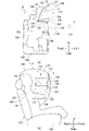
- FIG. 1 is a diagram illustrating an outline of a side airbag device 100 according to an embodiment of the invention.
- FIG. 1(a) is a perspective view showing part of the interior of the vehicle 102.
- FIG. 1(b) is a diagram showing the side airbag device 100 of FIG. 1(a) together with a vehicle seat 104.
- FIG. 1 is a diagram illustrating an outline of a side airbag device 100 according to an embodiment of the invention.
- FIG. 1(a) is a perspective view showing part of the interior of the vehicle 102.
- FIG. 1(b) is a diagram showing the side airbag device 100 of FIG. 1(a) together with a vehicle seat 104.
- FIG. 1 is a diagram illustrating an outline of a side airbag device 100 according to an embodiment of the invention.
- FIG. 1(a) is a perspective view showing part of the interior of the vehicle 102.
- FIG. 1(b) is a diagram showing the side airbag device 100 of FIG. 1(a) together
- the direction in which the occupant faces is called the front
- the opposite direction is called the rear.
- the right side of the occupant is referred to as the right direction
- the left side of the occupant is referred to as the left direction.
- the direction of the occupant's head is referred to as the upward direction
- the direction of the occupant's waist is referred to as the downward direction.
- the front, rear, left, right, up and down directions based on the occupant are indicated as Front, Back, Left, Right, Up, and Down as necessary.
- the side airbag device 100 is embedded in the vehicle center side portion of the seatback 106 of the vehicle seat 104, as indicated by the dotted line in FIG. 1(a).
- the vehicle seat 104 is a right front seat (for example, a driver's seat) in the vehicle 102 and has a seat back 106 and a seat cushion 108 on which an occupant sits.
- a vehicle seat 110 adjacent to the vehicle seat 104 is arranged in the vehicle 102 .
- the vehicle seat 110 is a left front seat (for example, a passenger seat) and has a seat back 112 and a seat cushion 114 .
- a side door 116 is positioned on the vehicle outer side of the vehicle seat 110 .
- the side airbag device 100 may be embedded in the side surface of the seat back 112 of the vehicle seat 110 on the vehicle center side, or may be embedded in the vehicle outer side surface of the seat back 112 , that is, the side facing the side door 116 . You may
- the side airbag device 100 includes a bag-like cushion 118, as shown in FIG. 1(b).
- the cushion 118 is inflated and deployed laterally of an occupant 122 (see FIG. 2) of the vehicle seat 104 using gas supplied from an inflator 120, which is a gas generator.
- the cushion 118 is formed into a bag-like shape by, for example, sewing the front and back of the base fabric that constitutes the surface of the cushion 118, or by weaving using OPW (One-Piece Woven).
- FIG. 2 is a diagram illustrating the side airbag device 100 when an occupant 122 is seated on the vehicle seat 104 of FIG. 1(b).
- FIGS. 2(a) and 2(b) illustrate the side airbag device 100 with the cushion 118 inflated and deployed, viewed from the vehicle front side and the vehicle width direction outer side, respectively.
- the cushion 118 includes a main chamber 124, a sub-chamber 126 and a non-inflatable panel 128 as shown in FIG. 1(b).
- the main chamber 124 has an inflator 120 inserted therein and inflates and deploys to the side of the occupant 122 of the vehicle seat 104 shown in FIG. 2(a).
- the sub-chamber 126 is a chamber formed of a base fabric separate from the main chamber 124 and connected to the main chamber 124 via a connecting portion 130 . Further, the sub-chamber 126 is provided so as to protrude from the occupant-side surface 127 of the main chamber 124 toward the vehicle seat 104, and as shown in FIG. It projects toward the occupant 122 of the seat 104 .
- the non-inflatable panel 128 is a separate three-sided panel that connects the main chamber 124 and the sub-chamber 126 and is connected to the first point 132 , the second point 134 and the third point 136 .
- the non-inflatable panel 128 is not limited to a separate panel, and may be integrated with the main chamber 124 or sub-chamber 126 .
- the first location 132 is located in the main chamber 124 and located above the lower end portion 137 of the subchamber 126 .
- the second location 134 is located in the sub-chamber 126 as shown in FIGS. , on the occupant side of the front end 138 of the .
- the third point 136 is located in the main chamber 124 as shown in FIGS. It is positioned forward of 140 or in the vicinity thereof.
- the vehicle 102 receives a lateral impact (see arrow A) due to a side collision, and the occupant 122 receives a lateral impact (see arrow B) toward the center of the vehicle due to inertia. It shows a state of moving toward the center.
- the movement line axis of the occupant 122 accompanying the side collision is the lateral direction indicated by the arrows A and B (that is, the vehicle width direction).
- the side airbag device 100 receives, for example, the head 142 of the occupant 122 moving in the direction indicated by the arrow B with the inflated and deployed cushion 118. As shown in FIG. 2(a), the side airbag device 100 receives, for example, the head 142 of the occupant 122 moving in the direction indicated by the arrow B with the inflated and deployed cushion 118. As shown in FIG. 2(a), the side airbag device 100 receives, for example, the head 142 of the occupant 122 moving in the direction indicated by the arrow B with the inflated and deployed cushion 118. As shown in FIG.
- the non-inflated panel 128 connecting the main chamber 124 and the sub-chamber 126 is located at the first and third locations 132 and 136 located in the main chamber 124 and the sub-chamber 126 . is pulled from the second point 134 of the . Therefore, the non-inflatable panel 128 can more reliably form a plane C between the main chamber 124 and the sub-chamber 126 to support the sub-chamber 126 when the cushion 118 is inflated and deployed.
- the sub-chamber 126 is set at a position higher than the shoulder 144 of the occupant 122 and lower than the head 142 in the inflated and deployed state.
- the head 142 of the occupant 122 moves in the direction indicated by the arrow B in FIG. 2(a) at the time of the side collision, and the head 142 moves downward in the vehicle as indicated by the arrow D in FIG. 2(b).
- the sub-chamber 126 protrudes toward the occupant 122 of the vehicle seat 104 to receive the head 142 of the occupant 122, and the non-inflatable panel 128 supports the sub-chamber 126. , the downward movement of the head 142 can be suppressed.
- the non-inflatable panel 128 forming the plane C receives the head 142 of the occupant 122, thereby suppressing the head 142 from moving forward.
- the protection performance of the passenger 122 can be improved.
- the portion corresponding to the front end of the main chamber 124 is positioned forward.
- the connection portion 130 of the cushion 118 is set further forward or the shapes of the main chamber 124 and the sub-chamber 126 are changed, the front end 138 of the sub-chamber 126 will be closer to the main chamber when the cushion 118 is inflated and deployed. It may be positioned forward of the third point 136 of 124 .
- the non-inflatable panel 128 is attached to the front end of the inflated and deployed cushion 118, that is, the front end 138 of the sub-chamber 126 and the front end of the main chamber 124, or a third portion 136, or near these front ends. is located in front of the cushion 118 containing the .
- the non-inflated panel 128 forms a plane C between the main chamber 124 and the sub-chamber 126 at the front or front end of the inflated and deployed cushion 118 . Therefore, the non-inflatable panel 128 can reliably receive the head 142 of the occupant 122 when the head 142 of the occupant 122 moves obliquely forward toward the center of the vehicle during a collision.
- the front direction of the occupant 122 seated on the vehicle seat 104 in a normal posture is defined as the front
- the back direction is defined as the rear.
- non-expandable panel 128 is triangular here, it is not limited to this, and may be polygonal such as trapezoid.
- the non-inflating panel is polygonal, by positioning the upper edge 146 of the non-inflating panel in the vicinity of the tension line F indicated by the dotted line in FIG. Plane C can be formed more reliably.
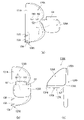
- FIG. 3 is a diagram illustrating the process of forming the cushion 118 of FIG. 1(b).
- the main chamber 124 has a plurality of (here, four) vent holes 148 on the surface 127 on the occupant side.
- the sub-chamber 126 is formed of a base fabric separate from the main chamber 124 and has a plurality of (here, four) gas introduction ports 150 .
- the sub-chamber 126 is brought closer to the main chamber 124, the gas introduction port 150 and the vent hole 148 are overlapped, and the surroundings thereof are sewn, etc. ) is formed.
- the gas introduction port 150 of the sub-chamber 126 communicates with the vent hole 148 of the main chamber 124, and introduces the gas exhausted from the vent hole 148 into the sub-chamber 126. be able to.
- the non-inflatable panel 128 is brought closer to the front end 138 of the subchamber 126, the front end 140 of the connecting portion 130, and the main chamber 124 as indicated by arrow H in FIG. 3(b). Subsequently, the non-inflatable panel 128 is connected to the first point 132 and third point 136 located in the main chamber 124 and the second point 134 located in the subchamber 126 as shown in FIG. 3(c). to connect the main chamber 124 and the sub-chamber 126 .
- the cushion 118 shown in FIG. 1(b) can be formed.
- Gas is introduced into the sub-chamber 126 through the gas introduction port 150 of the sub-chamber 126 from the vent hole 148 of the main chamber 124 of the inflated and deployed cushion 118 . Therefore, the main chamber 124 and the sub-chamber 126 can be inflated and deployed more reliably. Further, since the sub-chamber 126 is separate from the main chamber 124, it is easy to set an appropriate shape by using a base cloth separate from the main chamber 124. FIG.
- the sub-chamber 126 has a shape such that the front end 138 of the sub-chamber 126 becomes thinner and tapered toward the occupant, that is, the farther away from the main chamber 124 . As a result, when the head 142 of the occupant 122 moves toward the main chamber 124, the head 142 can be more reliably protected by the thick portion.
- FIG. 4 is a diagram illustrating a modified example of the cushion 118 of FIG. 1(b) and its sewing process.
- the main chamber 124A and the sub-chamber 126A are formed of an integral base fabric.
- the cushion 118A further has a duct 152.
- a duct 152 is formed between the main chamber 124A and the sub-chamber 126A to introduce gas from the main chamber 124A to the sub-chamber 126A.
- a part of the inflator 120A is inserted inside the main chamber 124A.
- the inflator 120A can be installed on the side of the seat back 106 of the vehicle seat 104 by stud bolts 156, 158 projecting from the main body 154. As shown in FIG.
- the main chamber 124A also has seam portions 160 and 162.
- the subchamber 126A has a sewing allowance 164.
- the sub-chamber 126A is positioned on the occupant side of the main chamber 124A with reference to the position of the duct 152 formed between the main chamber 124A and the sub-chamber 126A. Fold over to surface 127A.
- the sewing allowance 164 formed in the sub-chamber 126A overlaps the seams 160, 162 of the main chamber 124A as shown in FIG. 4(b).
- the sewing margin 164 and the seam portions 160, 162 are sewn in an overlapping state, and the sub-chamber 126A is folded upward as indicated by arrow J in FIG. 4(b).
- the uninflated panel 128A is connected to the first and third points 132A and 136A located in the main chamber 124A and the second point 134A located in the subchamber 126A. to connect the main chamber 124A and the sub-chamber 126A.
- a modified cushion 118A can be formed.
- the first location 132A and the third location 136A are located above the lower end portion 137A of the subchamber 126A.
- the second portion 134A is located closer to the occupant than the occupant-side surface 127A of the main chamber 124A.
- the cushion 118A can function as a delay chamber in which the sub-chamber 126A is inflated and deployed later than the main chamber 124A during inflation and deployment.
- the sub-chamber 126A shifts to the delay chamber while the occupant 122 moves toward the vehicle width direction center (far side) due to the inertia of the collision on the far side (far side) as seen from the occupant 122. , so that the head 142 of the occupant 122 can be received and protected more reliably.
- FIG. 5 is a diagram illustrating another modified example of the cushion 118 of FIG. 1(b).
- FIG. 5(a) shows a state in which a modified cushion 118B is inflated and deployed.
- FIG. 5(b) shows the cushion 118B of FIG. 5(a) viewed from above.
- FIG. 5C shows a state in which the cushion 118B attached to the side portion of the vehicle center side of the seat back 106 of the vehicle seat 104 is inflated and deployed.
- the modified cushion 118B is an integrated chamber that is inflated and deployed using gas supplied from the inflator 120B, and includes a main chamber 124B and sub-chambers 126B and 126C.
- the main chamber 124B includes a raised portion 166 and a base portion 168 as shown in FIG. 5(a).
- the raised portion 166 rises upward during inflation and deployment, and inflates and deploys to the side of the occupant 122 .
- the base portion 168 is inflated and deployed below the raised portion 166 .
- the sub-chamber 126B inflates and deploys from the base portion 168 toward the occupant and includes a support portion 170. 5(b) and 5(c), the support portion 170 protrudes toward the vehicle seat 104 from the occupant-side surface 127B of the raised portion 166, and ) is set at a position to receive the head 142 when it moves downward.
- the other sub-chamber 126C inflates and deploys from the base 168 to the side opposite to the occupant side and includes a support portion 172.
- the support portion 172 protrudes toward the other vehicle seat 110 adjacent to the vehicle seat 104 from the surface 127C of the raised portion 166 opposite to the occupant side (see FIG. 5(c)). It is set in a position to receive the head of the occupant 110 when the head moves downward.
- the cushion 118B further includes non-inflatable panels 128B, 128C.
- the non-inflatable panel 128B is connected to the first and third points 132B and 136B located on the ridge 166 and the second point 134B located on the support 170 shown in FIG. It connects the raised portion 166 of 124B and the support portion 170 of the subchamber 126B.
- the first location 132B is located above the support portion 170 of the sub-chamber 126B.
- the second portion 134B is located closer to the occupant than the occupant-side surface 127B of the raised portion 166 is.
- the third portion 136B is located at the same height as the support portion 170 of the subchamber 126B, but may be located above the support portion 170.
- the non-inflatable panel 128C is also connected to the first and third points 132C and 136C located on the ridge 166 and the second point 134C located on the support 172 shown in FIG. It connects the raised portion 166 of the main chamber 124B and the support portion 172 of the sub-chamber 126C. Note that the first location 132C is positioned above the support portion 172 of the sub-chamber 126C. The second portion 134C is located closer to the other vehicle seat 110 than the surface 127C of the raised portion 166 opposite to the occupant side. The third portion 136C is located at the same height as the support portion 172 of the subchamber 126C, but may be located above the support portion 172. In this manner, a modified cushion 118B can be formed.
- the support portion 170 of the sub-chamber 126B protrudes toward the occupant 122 of the vehicle seat 104 and receives the head 142. can be done. Further, the non-expanding panel 128B is pulled from the ridge 166 and the support 170 to form a plane between the ridge 166 and the support 170. FIG. Therefore, in the cushion 118B, the non-inflatable panel 128B can support the support portion 170, so that downward movement of the head 142 can be suppressed.
- the non-inflatable panel 128B forming a flat surface receives the head 142, thereby suppressing the forward movement of the head 142.
- the support portion 172 of the sub-chamber 126C projects toward the occupant of the vehicle seat 110 to move the head.
- the non-expanding panel 128C is pulled from the ridge 166 and the support 172 to form a plane between the ridge 166 and the support 172.
- FIG. Therefore, in the cushion 118B, the non-inflatable panel 128C can support the support portion 172, so that downward movement of the head can be suppressed.
- the non-inflatable panel 128C forming a plane receives the head, thereby suppressing forward movement of the head. can.
- the occupant protection performance can be improved.
- FIG. 6 is a diagram illustrating a modified example of the cushion 118B of FIG. 6(a) and 6(b) are diagrams showing states of the inflated and deployed modified cushion 118C viewed from above and from the side, respectively.
- the cushion 118C differs from the cushion 118B in that the raised portion 166A of the main chamber 124B protrudes upward and forward during inflation and deployment.
- the raised portion 166A protrudes forward. Therefore, the occupant-side surface 127D and the occupant-side opposite surface 127E of the raised portion 166A shown in FIG. It is longer than the occupant-side surface 127B of 166 and the occupant-side opposite surface 127C.
- the cushion 118C not only the support portions 170, 172 of the subchambers 126B, 126C and the panels 128B, 128C receive the head of the occupant, but also the surfaces 127D, 127E of the raised portion 166A sufficiently receive the head of the occupant. be able to.
- the cushion 118C the occupant protection performance can be improved.
- the panels 128B and 128C connect the protuberances 166 and 166A of the main chamber 124B and the support portions 170 and 172 of the subchambers 126B and 126C, respectively. may be omitted, and only the panel 128B may be provided.
- the panels 128, 128A, 128B, and 128C are all non-inflatable panels, they are not limited to this, and connect the main chambers 124, 124A, and 124B with the sub-chambers 126, 126A, 126B, and 126C during inflation and deployment. If possible, it may be a non-inflatable panel.
- the present invention can be used for a side airbag device having a bag-like cushion that inflates and deploys to the side of an occupant of a vehicle seat in the event of a vehicle side collision.
- SYMBOLS 100 Side airbag apparatus, 102... Vehicle, 104, 110... Vehicle seat, 106, 112... Seat back, 108, 114... Seat cushion, 116... Side door, 118, 118A, 118B, 118C... Cushion, 120, 120A... inflator, 122... occupant, 124, 124A, 124B... main chamber, 126, 126A, 126B, 126C... sub-chamber, 127, 127A... occupant side surface of main chamber, 127B, 127D... occupant side of protuberance Surfaces 127C, 127E... Surfaces opposite to the occupant side of the protuberances 128, 128A, 128B, 128C...
- Non-inflatable panels 130 Connecting portions 132, 132A, 132B, 132C... First locations 134, 134A , 134B, 134C... second location 136, 136A, 136B, 136C... third location 137, 137A... lower end portion of sub-chamber 138... front end of sub-chamber 140... front end of connection portion 142... occupant's head Part 144 Shoulder of occupant 146 Upper edge of non-inflatable panel 148 Vent hole 150 Gas introduction port 152 Duct 154 Main body of inflator 156, 158 Stud bolt 160, 162 Seam portion 164 Sewing margin 166, 166A Raised portion 168 Base portion 170, 172 Support portion
Landscapes
- Engineering & Computer Science (AREA)
- Mechanical Engineering (AREA)
- Aviation & Aerospace Engineering (AREA)
- Transportation (AREA)
- Air Bags (AREA)
Abstract
Description
Claims (11)
- インフレータと、車両用シートのシートバックの側部に設けられ、該インフレータから供給されるガスを利用して前記車両用シートの乗員の側方へ膨張展開する袋状のクッションとを備えるサイドエアバッグ装置において、
前記クッションは、
前記インフレータが内部に挿入されていて、前記車両用シートの乗員の側方へ膨張展開するメインチャンバと、
前記メインチャンバの乗員側の面から前記車両用シートに向かって突出するように設けられていて、該メインチャンバの膨張展開時に前記車両用シートの乗員に向かって突出し該乗員の頭部を受け止めるサブチャンバと、
前記メインチャンバと前記サブチャンバをつなぐパネルとを含み、
前記パネルは、
少なくとも前記サブチャンバの下端部分よりも上方で前記メインチャンバに接続され、前記メインチャンバの乗員側の面よりも乗員側で前記サブチャンバに接続されていることを特徴とするサイドエアバッグ装置。 - 前記パネルは、少なくとも3辺を有するパネルであって、
前記メインチャンバのうち前記サブチャンバの下端部分よりも上方に位置する第1箇所と、前記サブチャンバの前端のうち乗員側に位置する第2箇所と、前記メインチャンバのうち前記サブチャンバの下端部分の前方またはその付近の第3箇所とに接続されていることを特徴とする請求項1に記載のサイドエアバッグ装置。 - 前記パネルは、前記クッションの膨張展開時に該クッションの前方に位置していることを特徴とする請求項1または2に記載のサイドエアバッグ装置。
- 前記パネルは、前記クッションの前端に位置していることを特徴とする請求項3に記載のサイドエアバッグ装置。
- 前記メインチャンバは、前記インフレータから供給されたガスを排気するベントホールを有し、
前記サブチャンバは、前記メインチャンバとは別体の基布で形成されていて、前記メインチャンバと前記サブチャンバの接続部分で前記ベントホールに連通し該ベントホールから排気されたガスを導入するガス導入口を有することを特徴とする請求項1から4のいずれか1項に記載のサイドエアバッグ装置。 - 前記サブチャンバは、前記メインチャンバとは一体の基布で形成されていて、
前記クッションはさらに、前記メインチャンバと前記サブチャンバとの間に形成され、前記メインチャンバから前記サブチャンバへガスを導入するダクトを有することを特徴とする請求項1から4のいずれか1項に記載のサイドエアバッグ装置。 - 前記サブチャンバは、前記車両用シートに着座した乗員の肩部よりも高く頭部よりも低い位置に設定されていることを特徴とする請求項1から6のいずれか1項に記載のサイドエアバッグ装置。
- 前記メインチャンバは、膨張展開時に上方に隆起して、前記車両用シートの乗員の側方へ膨張展開する隆起部と、膨張展開時に該隆起部の下方に位置する基部とを含み、
前記サブチャンバは、前記基部から乗員側に膨張展開して、前記隆起部の乗員側の面よりも前記車両用シートに向かって突出し、乗員の頭部が下方に移動したとき頭部を受け止める支持部を含み、
前記パネルは、前記メインチャンバの前記隆起部と前記サブチャンバの前記支持部とをつなぐことを特徴とする請求項1に記載のサイドエアバッグ装置。 - 前記クッションはさらに、前記基部から乗員側の反対側に膨張展開する他のサブチャンバを含み、
前記他のサブチャンバは、前記隆起部の乗員側の反対側の面よりも前記車両用シートに隣接する他の車両用シートに向かって突出し、該他の車両用シートの乗員の頭部が下方に移動したとき頭部を受け止める他の支持部を含むことを特徴とする請求項8に記載のサイドエアバッグ装置。 - 前記クッションはさらに、前記メインチャンバの前記隆起部と前記他のサブチャンバの前記他の支持部とをつなぐ他のパネルを含むことを特徴とする請求項9に記載のサイドエアバッグ装置。
- 前記パネルは、非膨張のパネルであることを特徴とする請求項1から10のいずれか1項に記載のサイドエアバッグ装置。
Priority Applications (4)
| Application Number | Priority Date | Filing Date | Title |
|---|---|---|---|
| CN202280028962.0A CN117177885A (zh) | 2021-04-21 | 2022-04-20 | 侧面安全气囊装置 |
| KR1020237039556A KR20230174240A (ko) | 2021-04-21 | 2022-04-20 | 사이드 에어백 장치 |
| EP22791763.0A EP4328097B1 (en) | 2021-04-21 | 2022-04-20 | A vehicle seat comprising a side airbag device |
| JP2023515500A JP7568834B2 (ja) | 2021-04-21 | 2022-04-20 | サイドエアバッグ装置 |
Applications Claiming Priority (2)
| Application Number | Priority Date | Filing Date | Title |
|---|---|---|---|
| JP2021-071526 | 2021-04-21 | ||
| JP2021071526 | 2021-04-21 |
Publications (1)
| Publication Number | Publication Date |
|---|---|
| WO2022224992A1 true WO2022224992A1 (ja) | 2022-10-27 |
Family
ID=83722307
Family Applications (1)
| Application Number | Title | Priority Date | Filing Date |
|---|---|---|---|
| PCT/JP2022/018303 Ceased WO2022224992A1 (ja) | 2021-04-21 | 2022-04-20 | サイドエアバッグ装置 |
Country Status (5)
| Country | Link |
|---|---|
| EP (1) | EP4328097B1 (ja) |
| JP (1) | JP7568834B2 (ja) |
| KR (1) | KR20230174240A (ja) |
| CN (1) | CN117177885A (ja) |
| WO (1) | WO2022224992A1 (ja) |
Cited By (4)
| Publication number | Priority date | Publication date | Assignee | Title |
|---|---|---|---|---|
| CN117962802A (zh) * | 2024-03-07 | 2024-05-03 | 浙江松原汽车安全系统股份有限公司 | 一种远端气囊和汽车座椅 |
| JPWO2024095724A1 (ja) * | 2022-11-04 | 2024-05-10 | ||
| WO2025216031A1 (ja) * | 2024-04-11 | 2025-10-16 | オートリブ ディベロップメント エービー | エアバック装置 |
| EP4549257A4 (en) * | 2022-08-10 | 2025-12-10 | Autoliv Dev | SIDE AIRBAG DEVICE |
Citations (13)
| Publication number | Priority date | Publication date | Assignee | Title |
|---|---|---|---|---|
| JP2006008105A (ja) * | 2004-05-27 | 2006-01-12 | Toyoda Gosei Co Ltd | サイドエアバッグ装置 |
| JP2013147041A (ja) * | 2012-01-17 | 2013-08-01 | Toyota Motor Corp | 車両用サイドエアバッグ装置 |
| JP2014051138A (ja) | 2012-09-05 | 2014-03-20 | Toyota Motor Corp | 車両用安全装置 |
| US20150061267A1 (en) * | 2013-09-05 | 2015-03-05 | Ford Global Technologies, Llc | Vehicle side impact airbag with laterally extending thoracic chamber |
| JP2016007902A (ja) * | 2014-06-23 | 2016-01-18 | トヨタ自動車株式会社 | ファーサイドエアバッグ装置 |
| KR20170051824A (ko) * | 2015-11-02 | 2017-05-12 | 현대모비스 주식회사 | 센터에어백 장치 |
| JP2019031220A (ja) * | 2017-08-09 | 2019-02-28 | トヨタ自動車株式会社 | サイドエアバッグ装置 |
| JP2019034710A (ja) * | 2017-08-18 | 2019-03-07 | 現代自動車株式会社Hyundai Motor Company | 車両用エアバッグ |
| US20190161052A1 (en) * | 2017-11-15 | 2019-05-30 | TB Deu Abwicklungs-Aktiengesellschaft | Airbag for a vehicle occupant restraint system of a motor vehicle |
| WO2019110705A1 (de) * | 2017-12-08 | 2019-06-13 | Trw Automotive Gmbh | Seitengassack und fahrzeuginsassen-rückhaltesystem mit einem seitengassack |
| WO2020036048A1 (ja) * | 2018-08-14 | 2020-02-20 | オートリブ ディベロップメント エービー | サイドエアバッグ装置 |
| WO2020255817A1 (ja) * | 2019-06-20 | 2020-12-24 | 芦森工業株式会社 | サイドエアバッグ装置 |
| JP2021066426A (ja) * | 2019-10-17 | 2021-04-30 | オートリブ ディベロップメント エービー | サイドエアバッグ装置 |
Family Cites Families (5)
| Publication number | Priority date | Publication date | Assignee | Title |
|---|---|---|---|---|
| JP2010076640A (ja) * | 2008-09-26 | 2010-04-08 | Toyoda Gosei Co Ltd | エアバッグ装置 |
| US10246043B2 (en) * | 2017-02-03 | 2019-04-02 | Autoliv Asp, Inc. | Overhead airbag assemblies |
| CN111976644B (zh) * | 2019-05-21 | 2022-10-14 | 奥托立夫开发公司 | 安全气囊装置 |
| KR102661047B1 (ko) * | 2019-06-11 | 2024-04-26 | 현대모비스 주식회사 | 에어백 장치 |
| JP7243552B2 (ja) * | 2019-09-26 | 2023-03-22 | 豊田合成株式会社 | ファーサイドエアバッグ装置 |
-
2022
- 2022-04-20 EP EP22791763.0A patent/EP4328097B1/en active Active
- 2022-04-20 WO PCT/JP2022/018303 patent/WO2022224992A1/ja not_active Ceased
- 2022-04-20 JP JP2023515500A patent/JP7568834B2/ja active Active
- 2022-04-20 KR KR1020237039556A patent/KR20230174240A/ko active Pending
- 2022-04-20 CN CN202280028962.0A patent/CN117177885A/zh active Pending
Patent Citations (13)
| Publication number | Priority date | Publication date | Assignee | Title |
|---|---|---|---|---|
| JP2006008105A (ja) * | 2004-05-27 | 2006-01-12 | Toyoda Gosei Co Ltd | サイドエアバッグ装置 |
| JP2013147041A (ja) * | 2012-01-17 | 2013-08-01 | Toyota Motor Corp | 車両用サイドエアバッグ装置 |
| JP2014051138A (ja) | 2012-09-05 | 2014-03-20 | Toyota Motor Corp | 車両用安全装置 |
| US20150061267A1 (en) * | 2013-09-05 | 2015-03-05 | Ford Global Technologies, Llc | Vehicle side impact airbag with laterally extending thoracic chamber |
| JP2016007902A (ja) * | 2014-06-23 | 2016-01-18 | トヨタ自動車株式会社 | ファーサイドエアバッグ装置 |
| KR20170051824A (ko) * | 2015-11-02 | 2017-05-12 | 현대모비스 주식회사 | 센터에어백 장치 |
| JP2019031220A (ja) * | 2017-08-09 | 2019-02-28 | トヨタ自動車株式会社 | サイドエアバッグ装置 |
| JP2019034710A (ja) * | 2017-08-18 | 2019-03-07 | 現代自動車株式会社Hyundai Motor Company | 車両用エアバッグ |
| US20190161052A1 (en) * | 2017-11-15 | 2019-05-30 | TB Deu Abwicklungs-Aktiengesellschaft | Airbag for a vehicle occupant restraint system of a motor vehicle |
| WO2019110705A1 (de) * | 2017-12-08 | 2019-06-13 | Trw Automotive Gmbh | Seitengassack und fahrzeuginsassen-rückhaltesystem mit einem seitengassack |
| WO2020036048A1 (ja) * | 2018-08-14 | 2020-02-20 | オートリブ ディベロップメント エービー | サイドエアバッグ装置 |
| WO2020255817A1 (ja) * | 2019-06-20 | 2020-12-24 | 芦森工業株式会社 | サイドエアバッグ装置 |
| JP2021066426A (ja) * | 2019-10-17 | 2021-04-30 | オートリブ ディベロップメント エービー | サイドエアバッグ装置 |
Non-Patent Citations (1)
| Title |
|---|
| See also references of EP4328097A4 |
Cited By (6)
| Publication number | Priority date | Publication date | Assignee | Title |
|---|---|---|---|---|
| EP4549257A4 (en) * | 2022-08-10 | 2025-12-10 | Autoliv Dev | SIDE AIRBAG DEVICE |
| JPWO2024095724A1 (ja) * | 2022-11-04 | 2024-05-10 | ||
| WO2024095724A1 (ja) * | 2022-11-04 | 2024-05-10 | オートリブ ディベロップメント エービー | 車両用サイドエアバッグ装置 |
| JP7762316B2 (ja) | 2022-11-04 | 2025-10-29 | オートリブ ディベロップメント エービー | 車両用サイドエアバッグ装置 |
| CN117962802A (zh) * | 2024-03-07 | 2024-05-03 | 浙江松原汽车安全系统股份有限公司 | 一种远端气囊和汽车座椅 |
| WO2025216031A1 (ja) * | 2024-04-11 | 2025-10-16 | オートリブ ディベロップメント エービー | エアバック装置 |
Also Published As
| Publication number | Publication date |
|---|---|
| CN117177885A (zh) | 2023-12-05 |
| KR20230174240A (ko) | 2023-12-27 |
| JPWO2022224992A1 (ja) | 2022-10-27 |
| EP4328097B1 (en) | 2026-04-01 |
| JP7568834B2 (ja) | 2024-10-16 |
| EP4328097A1 (en) | 2024-02-28 |
| EP4328097A4 (en) | 2025-03-26 |
Similar Documents
| Publication | Publication Date | Title |
|---|---|---|
| JP6714750B2 (ja) | エアバッグ装置 | |
| JP6673392B2 (ja) | 乗員保護装置 | |
| JP6411965B2 (ja) | 乗員保護装置 | |
| JP7372867B2 (ja) | サイドエアバッグ装置 | |
| JP4420067B2 (ja) | 車両用エアバッグ装置 | |
| JP7568834B2 (ja) | サイドエアバッグ装置 | |
| US11752965B2 (en) | Side airbag device and method for manufacturing side airbag device | |
| US7350811B2 (en) | Side airbag apparatus | |
| CN103707840A (zh) | 车辆用乘员安全装置 | |
| JP2003285713A (ja) | サイドエアバッグ装置 | |
| JP2008110660A (ja) | 車両用サイドエアバッグ装置 | |
| JP7220172B2 (ja) | サイドエアバッグ装置およびニーエアバッグ装置 | |
| CN109963754A (zh) | 侧气囊装置 | |
| CN111845613B (zh) | 侧气囊装置 | |
| KR20230016684A (ko) | 에어백 장치 | |
| CN110871765B (zh) | 气囊装置 | |
| CN115214518B (zh) | 远侧气囊装置 | |
| JP6854358B2 (ja) | サイドエアバッグ装置 | |
| JP6517659B2 (ja) | 車両用乗員保護装置 | |
| CN119866286A (zh) | 乘员保护装置 | |
| JP4909556B2 (ja) | エアバッグ | |
| WO2023282019A1 (ja) | エアバッグ装置 | |
| WO2022224844A1 (ja) | サイドエアバッグ装置 | |
| JP4614035B2 (ja) | 頭部保護エアバッグ装置 | |
| KR102352151B1 (ko) | 자동차의 운전석 에어백 장치 |
Legal Events
| Date | Code | Title | Description |
|---|---|---|---|
| 121 | Ep: the epo has been informed by wipo that ep was designated in this application |
Ref document number: 22791763 Country of ref document: EP Kind code of ref document: A1 |
|
| WWE | Wipo information: entry into national phase |
Ref document number: 2023515500 Country of ref document: JP |
|
| ENP | Entry into the national phase |
Ref document number: 20237039556 Country of ref document: KR Kind code of ref document: A |
|
| WWE | Wipo information: entry into national phase |
Ref document number: 1020237039556 Country of ref document: KR |
|
| WWE | Wipo information: entry into national phase |
Ref document number: 2022791763 Country of ref document: EP |
|
| NENP | Non-entry into the national phase |
Ref country code: DE |
|
| ENP | Entry into the national phase |
Ref document number: 2022791763 Country of ref document: EP Effective date: 20231121 |
|
| WWG | Wipo information: grant in national office |
Ref document number: 2022791763 Country of ref document: EP |