WO2022227789A1 - 一种光交换装置、光交换方法、光交换节点以及系统 - Google Patents
一种光交换装置、光交换方法、光交换节点以及系统 Download PDFInfo
- Publication number
- WO2022227789A1 WO2022227789A1 PCT/CN2022/076155 CN2022076155W WO2022227789A1 WO 2022227789 A1 WO2022227789 A1 WO 2022227789A1 CN 2022076155 W CN2022076155 W CN 2022076155W WO 2022227789 A1 WO2022227789 A1 WO 2022227789A1
- Authority
- WO
- WIPO (PCT)
- Prior art keywords
- wavelength
- sub
- light beam
- lens group
- optical switching
- Prior art date
- Legal status (The legal status is an assumption and is not a legal conclusion. Google has not performed a legal analysis and makes no representation as to the accuracy of the status listed.)
- Ceased
Links
Images




Classifications
-
- G—PHYSICS
- G02—OPTICS
- G02B—OPTICAL ELEMENTS, SYSTEMS OR APPARATUS
- G02B6/00—Light guides; Structural details of arrangements comprising light guides and other optical elements, e.g. couplings
- G02B6/24—Coupling light guides
- G02B6/26—Optical coupling means
- G02B6/35—Optical coupling means having switching means
- G02B6/354—Switching arrangements, i.e. number of input/output ports and interconnection types
- G02B6/356—Switching arrangements, i.e. number of input/output ports and interconnection types in an optical cross-connect device, e.g. routing and switching aspects of interconnecting different paths propagating different wavelengths to (re)configure the various input and output links
-
- H—ELECTRICITY
- H04—ELECTRIC COMMUNICATION TECHNIQUE
- H04Q—SELECTING
- H04Q11/00—Selecting arrangements for multiplex systems
- H04Q11/0001—Selecting arrangements for multiplex systems using optical switching
- H04Q11/0005—Switch and router aspects
-
- G—PHYSICS
- G02—OPTICS
- G02B—OPTICAL ELEMENTS, SYSTEMS OR APPARATUS
- G02B6/00—Light guides; Structural details of arrangements comprising light guides and other optical elements, e.g. couplings
- G02B6/24—Coupling light guides
- G02B6/26—Optical coupling means
- G02B6/28—Optical coupling means having data bus means, i.e. plural waveguides interconnected and providing an inherently bidirectional system by mixing and splitting signals
- G02B6/293—Optical coupling means having data bus means, i.e. plural waveguides interconnected and providing an inherently bidirectional system by mixing and splitting signals with wavelength selective means
-
- G—PHYSICS
- G02—OPTICS
- G02B—OPTICAL ELEMENTS, SYSTEMS OR APPARATUS
- G02B6/00—Light guides; Structural details of arrangements comprising light guides and other optical elements, e.g. couplings
- G02B6/24—Coupling light guides
- G02B6/26—Optical coupling means
- G02B6/28—Optical coupling means having data bus means, i.e. plural waveguides interconnected and providing an inherently bidirectional system by mixing and splitting signals
- G02B6/293—Optical coupling means having data bus means, i.e. plural waveguides interconnected and providing an inherently bidirectional system by mixing and splitting signals with wavelength selective means
- G02B6/29304—Optical coupling means having data bus means, i.e. plural waveguides interconnected and providing an inherently bidirectional system by mixing and splitting signals with wavelength selective means operating by diffraction, e.g. grating
- G02B6/29305—Optical coupling means having data bus means, i.e. plural waveguides interconnected and providing an inherently bidirectional system by mixing and splitting signals with wavelength selective means operating by diffraction, e.g. grating as bulk element, i.e. free space arrangement external to a light guide
- G02B6/29311—Diffractive element operating in transmission
-
- H—ELECTRICITY
- H04—ELECTRIC COMMUNICATION TECHNIQUE
- H04Q—SELECTING
- H04Q11/00—Selecting arrangements for multiplex systems
- H04Q11/0001—Selecting arrangements for multiplex systems using optical switching
- H04Q11/0005—Switch and router aspects
- H04Q2011/0007—Construction
- H04Q2011/0015—Construction using splitting combining
-
- H—ELECTRICITY
- H04—ELECTRIC COMMUNICATION TECHNIQUE
- H04Q—SELECTING
- H04Q11/00—Selecting arrangements for multiplex systems
- H04Q11/0001—Selecting arrangements for multiplex systems using optical switching
- H04Q11/0005—Switch and router aspects
- H04Q2011/0007—Construction
- H04Q2011/0026—Construction using free space propagation (e.g. lenses, mirrors)
Definitions
- the present application relates to the field of optical fiber communications, and in particular, to an optical switching device, an optical switching method, an optical switching node, and a system.
- the switching of the optical signal transmission direction can be performed through the optical switching node.
- the optical switching node may be a reconfigurable optical add drop multiplexer (ROADM) or an optical switching node within a data center network.
- ROADM reconfigurable optical add drop multiplexer
- a plurality of wavelength selective switches are used to interconnect to build an optical switching node, so as to realize the exchange of different transmission directions of optical signals.
- WSS wavelength selective switches
- the WSS obtains the input optical signal through the included multiple input fibers
- the WSS outputs the optical signal through the included multiple output fibers
- both the input fiber and the output fiber are one-dimensional along the target direction. arrangement. It can be seen that the WSS can only realize the exchange of the transmission direction in the target direction.
- the optical signal can only exchange the transmission direction in the target direction, the number of output ports of the output fiber of the WSS is limited, so that the current WSS cannot realize the exchange of the optical signal in more transmission directions.
- Embodiments of the present invention provide an optical switching device, an optical switching method, an optical switching node, and a system, which are used to implement switching of optical signals in more transmission directions.
- a first aspect of the embodiments of the present invention provides an optical switching device, the optical switching device includes an input port, a first dispersion element, a first switching engine, a first beam combiner, a first lens group, and a second dispersion element element, a second beam combiner, a second switching engine and an output port;
- the input port is used to obtain the first beam;
- the first dispersion element is used to receive the first beam from the input port, and use
- the first dispersing element is also used to inject the multiple first sub-wavelength beams into the first switching engine;
- the first The switching engine is used for changing the transmission direction of the first sub-wavelength light beam to be incident on a plurality of first beam combining areas included in the first beam combining part;
- the first beam combining area is used for The first sub-wavelength light beams are combined to form a second light beam, and the first beam combining element is used for multiplexing the second light beams into the first lens group;
- the optical switching device shown in this aspect can change the transmission direction of at least one sub-wavelength beam of the first beam obtained by the input port along the port plane XY and along the wavelength plane ZY, and realize the sub-wavelength beam along the port plane XY. and the deflection of the transmission direction along the wavelength plane ZY. It is ensured that the optical switching device shown in this embodiment can realize that the sub-wavelength beams obtained by the input ports located at any positions of the input port array can be exchanged to the output ports at any positions included in the output port array, thereby realizing the realization of the The deflection of the wavelength beam in any direction effectively avoids the disadvantage of the limited number of input ports and output ports included in the optical switching device.
- the transmission direction of the sub-wavelength beam can be changed multiple times through the first switching engine and the second switching engine, the insertion loss of changing the transmission direction of the sub-wavelength beam is reduced and the accuracy of exchanging the transmission direction of the sub-wavelength beam is improved. sex.
- At least one lens included in the first lens group is configured to converge the multiple second light beams along the wavelength plane and/or the port plane to the second dispersion member.
- the first lens group shown in this aspect can converge the multiple second light beams to the second dispersion member along the wavelength plane and the port plane, so as to ensure that the second light beams can be successfully transmitted to the on the second switching engine to achieve the purpose of changing the transmission direction.
- the first dispersion member, the second dispersion member, the first beam combiner and the second beam combiner are the same grating, so The first switching engine and the second switching engine are the same switching engine, and the optical switching device further includes a switching separation module; the first transmission area of the switching separation module is used to receive the first light beam, and is used to The first light beam is transmitted to the first dispersing member in a transmissive manner; the reflection area of the exchange and separation module is used to receive the second light beam and transmit the second light beam to the reflective manner. the first lens group; the second transmission area of the exchange and separation module is used for receiving the third light beam and for transmitting the third light beam to the output port in a transmission manner.
- the optical switching device can realize the deflection of the transmission direction of the first sub-wavelength beam and the transmission direction of the second sub-wavelength beam through only one switching device, which can improve the utilization rate of the optical device and reduce the optical switching.
- the overall volume of the device and the space utilization rate of the optical switching device are improved.
- the optical switching device further includes a first switching and splitting module and a second switching and splitting module; the transmission area of the first switching and splitting module is used to receive the first light beam, and is used to The light beam is transmitted to the first dispersing member in a transmissive manner; the reflection area of the first exchange and separation module is used for receiving the second light beam and for transmitting the second light beam to the said second light beam in a reflective manner the second exchange and separation module; the reflection area of the second exchange and separation module is used for receiving the second light beam and for transmitting the second light beam to the second dispersing member in a reflective manner; the first The transmission area of the two exchange and separation modules is used for receiving the third light beam and for transmitting the third light beam to the output port in a transmission manner.
- the process of decomposing the first beam to form a plurality of first sub-wavelength beams by a first grating can also realize the process of decomposing a plurality of first sub-wavelength beams.
- the process of decomposing the second light beam to form a plurality of second sub-wavelength light beams is realized by a second grating, and the second grating can also realize the function of combining the plurality of second sub-wavelength light beams to form a third light beam.
- the utilization rate of the optical device is effectively improved, the overall volume of the optical switching device is reduced, and the space utilization rate of the optical switching device is improved.
- the second light beam whose transmission direction is changed through the first switching engine shown in this aspect can be transmitted to the second switching engine through the first switching separation module and the second switching separation module in turn, and then the second switching engine can carry out the transmission.
- the deflection of the transmission direction because the first light beam is transmitted to the first exchange engine through the first exchange and separation module, and the third light beam from the second exchange engine is output through the second exchange and separation module, which can ensure that the output third light beam is accurately directed to the first exchange engine.
- the output port array transmission effectively ensures the separation of the transmission direction of the first beam and the transmission direction of the third beam, so as to improve the deflection accuracy of the beam transmission direction.
- the distance between the switching separation module included in the optical switching device and the first lens group is equal to the equivalent focal length of the first lens group.
- the optical switching device includes an input port array and an output port array, and the input port array includes a plurality of the input ports along the first direction and the third direction respectively.
- the output port array includes a plurality of the output ports along the first direction and the third direction respectively, and the first direction and the third direction are both perpendicular to the transmission direction of the first light beam , and the first direction and the third direction are perpendicular to each other.
- the plurality of input ports included in the output port array shown in this aspect are arranged in a two-dimensional direction, and the plurality of output ports included in the output port array are also arranged in a two-dimensional direction, which effectively ensures the optical fiber shown in this aspect.
- the exchange device can realize the exchange of sub-wavelength beams in more transmission directions.
- the optical switching device includes a first number of output ports along a first direction, and the optical switching device includes a second number of outputs along a third direction port, the first direction and the third direction are both perpendicular to the transmission direction of the first beam; the number of the first beam combining area included in the first beam combiner along the first direction is less than or equal to the first number, and the number of the first bundling areas included in the first bundling piece along the third direction is less than or equal to the second quantity; the second bundling piece The number of the second bundling areas included in the first direction is less than or equal to the first quantity, and the second bundling areas included in the third direction by the second bundling member The number of is less than or equal to the second number.
- the optical switching device includes a plurality of the input ports, and a second lens group is further included between the plurality of input ports and the first dispersion member,
- the second lens group includes an odd number of lenses; the second lens group is used for multiplexing the first light beams into the first area and the second area of the first dispersing member at different incident angles place.
- the first region and the second region overlap on the first dispersion member.
- the multiple first beams are incident on the same position of the first dispersing member, which can ensure that the multiple first sub-wavelength beams emitted from the first dispersing member are incident on all the first sub-wavelength beams in the direction perpendicular to the first switching engine.
- the first switching engine reduces the degradation of the bandwidth of the multiple first sub-wavelength light beams incident on the first switching engine.
- the first dispersion member is configured to emit the different first sub-wavelength light beams at different exit angles.
- a third lens group is further included between the first dispersion element and the first exchange engine, and the third lens group includes an odd number of lenses; the The third lens group is used for injecting the multiple first sub-wavelength light beams into the first switching engine in a direction perpendicular to the first switching engine.
- the first switching engine includes a plurality of first switching regions, and the first sub-wavelength light beams emitted from different first switching regions are incident on different all Describe the first beam combining area.
- the wavelengths of the multiplexed first sub-wavelength light beams received by the same first switching area are all different.
- the wavelengths of the multiplex first sub-wavelength light beams received by the same first switching area are at least partially the same.
- a collimating lens group is included between the input port and the first dispersion member, the collimating lens group includes one or more collimating lenses, and the input port is located in the collimating lens. At the front focus of the lens group, the collimating lens group is used for collimating the first light beam from the input port.
- the collimating lens group can correct the first light beam from the input port.
- the light beam is collimated, which effectively reduces the attenuation of the optical power of the first light beam.
- the first switch engine when the sub-wavelength beam ⁇ M included in the first light beam is incident on the first switch engine, the first switch engine changes along the wavelength plane ZY and the port plane XY at the same time The transmission direction of the sub-wavelength beam ⁇ M, when the sub-wavelength beam ⁇ M is incident on the second switching engine, the second switching engine changes the transmission direction of the sub-wavelength beam ⁇ M along the wavelength plane ZY.
- the sub-wavelength light beam ⁇ M is any first light beam obtained by any output port, and any sub-wavelength light beam included.
- the first switch engine when the sub-wavelength beam ⁇ M included in the first light beam is incident on the first switch engine, the first switch engine changes along the wavelength plane ZY and the port plane XY at the same time The propagation direction of the sub-wavelength beam ⁇ M.
- the second switching engine changes the transmission direction of the sub-wavelength beam ⁇ M along the port plane XY.
- the first switching engine when the sub-wavelength beam ⁇ M included in the first light beam is incident on the first switching engine, the first switching engine simultaneously extends along the wavelength plane ZY and the port plane XY Change the transmission direction of the sub-wavelength beam ⁇ M.
- the second switching engine When the sub-wavelength beam ⁇ M is incident on the second switching engine, the second switching engine simultaneously changes the transmission direction of the sub-wavelength beam ⁇ M along the wavelength plane ZY and the port plane XY.
- the first switching engine when the sub-wavelength beam ⁇ M included in the first light beam is incident on the first switching engine, the first switching engine changes the sub-wavelength beam ⁇ M along the wavelength plane ZY. transfer direction.
- the second switching engine When the sub-wavelength beam ⁇ M is incident on the second switching engine, the second switching engine simultaneously changes the transmission direction of the sub-wavelength beam ⁇ M along the wavelength plane ZY and the port plane XY.
- the first switching engine when the sub-wavelength beam ⁇ M included in the first light beam is incident on the first switching engine, the first switching engine changes the sub-wavelength beam ⁇ M along the wavelength plane ZY. transfer direction.
- the second switching engine changes the transmission direction of the sub-wavelength beam ⁇ M along the port plane XY.
- the first switching engine when the sub-wavelength beam ⁇ M included in the first light beam is incident on the first switching engine, the first switching engine changes the sub-wavelength beam ⁇ M along the port plane XY. transfer direction.
- the second switching engine changes the transmission direction of the sub-wavelength beam ⁇ M along the port plane XY and the wavelength plane ZY.
- the first switching engine when the sub-wavelength beam ⁇ M included in the first light beam is incident on the first switching engine, the first switching engine changes the sub-wavelength beam ⁇ M along the port plane XY. transfer direction.
- the second switching engine changes the transmission direction of the sub-wavelength beam ⁇ M along the wavelength plane ZY.
- a fourth lens group is included between the first exchange engine and the first beam combiner, and the fourth lens group includes an odd number of lenses.
- the fourth lens group is used to transmit the first sub-light wavelength beams emitted from different first exchange areas to the different first beam combining areas included in the first beam combining member, and is used to The first sub-wavelength light beams emitted from the same first exchange area are converged on the first beam combining area.
- a fifth lens group is further disposed between the second dispersion member and the second exchange engine, and the fifth lens group includes an odd number of lenses.
- the fifth lens group is used for condensing the multiple second sub-wavelength light beams to the second switching engine.
- a sixth lens group is included between the second exchange engine and the second beam combiner, and the sixth lens group includes an odd number of lenses.
- the sixth lens group is used for condensing the multiple second sub-wavelength light beams to the second beam combiner.
- a seventh lens group may be further included between the second beam combiner and the output port, and the seventh lens group includes an odd number of lenses.
- the seventh lens group is used for condensing multiple third light beams onto the output port, so as to output the third light beams from the optical switching device.
- the second switching engine includes a plurality of second switching regions, and the second sub-wavelength light beams emitted from different second switching regions are incident on different all the second beam combining area.
- the wavelengths of the multiple second sub-wavelength light beams received by the same second switching area are all different.
- the wavelengths of the multiple second sub-wavelength light beams received by the same second switching area are at least partially the same.
- the transmission area of the exchange and separation module has a transparent structure, so as to ensure that the light beam can be transmitted through the transmission area.
- the reflection area of the exchange and separation module is a reflection film on the surface of the exchange and separation module, so as to ensure that the optical signal can be transmitted through the reflection of the reflection film.
- a second aspect of the embodiments of the present invention provides an optical switching method, which is applied to an optical switching device.
- the optical switching device includes an input port, a first dispersion member, a first switching engine, a first beam combining member, a first A lens group, a second dispersive element, a second beam combiner, a second exchange engine and an output port, the method includes: acquiring a first light beam through the input port; inputting the first beam of the port, decomposing the first beam into multiple first sub-wavelength beams, and injecting the multiple first sub-wavelength beams into the first switching engine; A switching engine changes the transmission direction of the first sub-wavelength beam to be incident on a plurality of first beam combining areas included in the first beam combining part; The first sub-wavelength light beams are combined to form a second light beam, and multiple second light beams are incident on the first lens group; the second dispersing element, the first lens group includes an odd number of lenses; each path of the second light beam is decomposed into multiple paths of second
- the first dispersion member, the second dispersion member, the first beam combiner, and the second beam combiner are the same grating, so The first switching engine and the second switching engine are the same switching engine, the optical switching device further includes a switching separation module, and after acquiring the first light beam through the input port, the method further includes: passing the The first transmission area of the exchange and separation module receives the first light beam, and transmits the first light beam to the first dispersion member in a transmission manner; the second light beam is received through the reflection area of the exchange and separation module and transmit the second beam to the first lens group in a reflective manner; receive the third beam through the second transmission area of the exchange and separation module, and transmit the third beam as a transmitted way to the output port.
- the first dispersing member and the first beam combining member are the same first grating, and the second dispersing member and the second beam combining member With the same second grating, the optical switching device further includes a first switching separation module and a second switching separation module, and after obtaining the first light beam through the input port, the method further includes: separating through the first switching The transmission area of the module receives the first light beam, and transmits the first light beam to the first dispersion member in a transmission manner; the second light beam is received through the reflection area of the first exchange and separation module, and transmit the second light beam to the second exchange and separation module in a reflective manner; receive the second light beam through the reflection area of the second exchange and separation module, and reflect the second light beam transmitting to the second dispersing element; receiving the third light beam through the transmission area of the second exchange and separation module, and transmitting the third light beam to the output port in a transmission manner.
- a third aspect of the present invention provides an optical switching node, which includes a plurality of optical switching devices, and different optical switching devices are connected by optical fibers.
- a fourth aspect of the present invention provides an optical communication system, including a plurality of optical switching nodes, and the optical switching nodes are as shown in the above-mentioned second aspect.
- Fig. 1a is a structural example diagram of an optical switching node provided by the application.
- Fig. 1b is another structural example diagram of the optical switching node provided by the application.
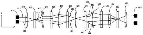
- Fig. 2a is a structural example diagram of the first embodiment of the optical switching device provided by the application along the wavelength plane;
- Fig. 2b is a structural example diagram of the first embodiment of the optical switching device provided by the application along the port plane;
- FIG. 3 a is an example diagram of the first light beam being decomposed by the first dispersing element provided by the application;
- Fig. 3b is a structural example diagram of an embodiment of the first dispersion member provided by the application.
- FIG. 4 is an exemplary structural diagram of an embodiment of an input port array and an output port array provided by the application;
- FIG. 5 is a schematic diagram of a partial structure of an embodiment of the optical switching device provided by the application along the wavelength plane;
- FIG. 6 is an exemplary structural diagram of an embodiment of the first switching engine provided by the application.
- FIG. 7 is an exemplary structural diagram of the second embodiment of the optical switching device provided by the application along the wavelength plane;
- FIG. 8 is a structural example diagram of the second embodiment of the optical switching device provided by the application along the port plane;
- FIG. 9 is an exemplary structural diagram of an embodiment of the switching separation module provided by the application.
- FIG. 10 is an exemplary structural diagram of the third embodiment of the optical switching device provided by the application along the wavelength plane;
- FIG. 11 is a schematic structural diagram of the third embodiment of the optical switching device provided by the application along the port plane;
- FIG. 12 is an exemplary structural diagram of the fourth embodiment of the optical switching device provided by the application along the wavelength plane;
- 13 is a flow chart of the steps of the first embodiment of the method for optical switching provided by the application.
- FIG. 14 is a flowchart of steps of the second embodiment of the method for optical switching provided by the application.
- 15 is a flowchart of steps of a third embodiment of the method for optical switching provided by the application.
- FIG. 16 is a schematic structural diagram of an embodiment of an optical communication system provided by the present application.
- the present application provides an optical switching node, where the optical switching node is a ROADM or an optical switching node within a data center network.
- This embodiment is exemplified by taking the ROADM as an example.
- the optical switching node may also be referred to as a wavelength crossconnect (WXC), an optical crossconnect (OXC), an optical switching node, or a wavelength switching node, etc., the embodiments of the present application There is no specific restriction on this.
- WXC wavelength crossconnect
- OXC optical crossconnect
- FIG. 1a is a schematic structural diagram of the optical switching node provided by the present application.
- the ROADM shown in FIG. 1a includes four WSSs on the input side (ie WSS110, WSS111, WSS112 and WSS113) and four WSSs on the output side (ie WSS210, WSS211, WSS212 and WSS213).
- Each WSS on the input side is a 1*4 (ie, one input port, four output port) WSS
- each WSS on the output side is a 4*1 (ie, four input ports, one output port) WSS.
- the output port of each WSS on the input side is connected to the input port of each WSS on the output side.
- the eight WSSs shown in this embodiment are located at different positions, and this embodiment does not limit the number of WSSs included in the ROADM and the positions where each WSS is located.
- the WSSs located at different locations are used to exchange the transmission direction of the optical signal, so as to realize flexible scheduling of the optical signal.
- the WSS110 can propagate the optical signal to any WSS included on the output side that is connected to the WSS110 through an optical fiber, so as to realize the exchange of optical signals in different directions.
- the The WSS110 is connected to the WSS210, WSS211, WSS212, and WSS213 through optical fibers, and the WSS110 can transmit optical signals to any one of the WSS210, WSS211, WSS212, and WSS213.
- a plurality of input ports on the input side shown in FIG. 1a may be arranged in a one-dimensional direction, or a plurality of input ports may be arranged in a two-dimensional direction.
- the plurality of output ports on the output side shown in this embodiment may be arranged in a one-dimensional direction, or the plurality of output ports may be arranged in a two-dimensional direction.
- the ROADM includes multiple WSSs as an example.
- the structure of the ROADM can also be referred to as shown in FIG. 1b, wherein FIG.
- the ROADM may include one WSS200.
- the WSS200 includes multiple input ports and multiple output ports as an example, and this embodiment does not limit the number of input ports and the number of output ports.
- WSS200 includes 4 input ports and 4 output ports.
- the plurality of input ports included in the WSS2200 may be arranged in a one-dimensional direction, or the plurality of input ports may be arranged in a two-dimensional direction.
- a plurality of output ports may be arranged in a one-dimensional direction, or a plurality of output ports may be arranged in a two-dimensional direction.
- the optical switching device is any WSS shown in FIG. 1a or FIG. 1b as an example.
- the WSS shown in this embodiment is the WSS 200 shown in FIG. 1b.
- 2a is a schematic structural diagram of the optical switching device along a wavelength plane
- FIG. 2b is a structural schematic diagram of the optical switching device along a port plane.
- the wavelength plane ZY and the port plane XY shown in this embodiment are planes perpendicular to each other, wherein the wavelength plane ZY is a plane along the second direction Y and the third direction Z at the same time, and the port plane XY is a plane along the first direction at the same time.
- the planes of X and the second direction Y, and the first direction X, the second direction Y and the third direction Z are all mutually perpendicular directions.
- the transmission direction of the first light beam obtained through the input port of the optical switching device shown in this embodiment is the second direction Y shown above.
- the third direction Z shown in this embodiment may also be referred to as a wavelength direction or a dispersion direction, and the first direction X may also be referred to as a switching direction or a port direction.
- the optical switching device shown in this embodiment includes an input port array 400, a first dispersive element 402, a first switching engine 404, a first beam combiner 406, a first lens group 408, a second dispersive element 409, a second The combiner 483 , the second switching engine 481 and the output port array 600 .
- the first dispersing element 402 is used to receive the first light beam 301 from the input port.
- the first dispersing element 402 is used to decompose the first light beam 301 to form a plurality of first sub-wavelength light beams with different wavelengths, for example, to form a first sub-wavelength light beam with wavelength ⁇ 1 , a first sub-wavelength light beam with wavelength ⁇ 2
- the specific value of N is not limited in this example, as long as ⁇ 1 , ⁇ 2 to ⁇ N are different from each other.
- the first dispersing member 402 can make the first sub-wavelength light beam with wavelength ⁇ 1 , the first sub-wavelength light beam with wavelength ⁇ 2 and the first sub-wavelength light beam with wavelength ⁇ N respectively exit from the first sub-wavelength light beam with different exit angles
- a dispersive element 402 exits for transmission.
- the first direction X is the direction in which the outgoing first sub-wavelength light beams spread out, that is, the first dispersing element 402 enables the plurality of first sub-wavelength light beams to obtain angular dispersion.
- the propagation direction of the first light beam 301 is the direction Y shown in FIG. 3 a
- the third direction Z is a direction perpendicular to both the first direction X and the propagation direction Y of the first light beam 301 .
- this example takes the first dispersive element 402 as a reference, with reference to FIG. 3b, this example takes the first dispersive element 402 as a volume grating as an example for illustrative illustration: in this example, the third direction Z is the same as that of the grating.
- the lines 303 are parallel to each other, and the first direction X is a direction perpendicular to the grating scribe lines 303 . It can be seen that the third direction Z is perpendicular to the first direction X.
- This definition takes the first switching engine 404 as a reference.
- the first switching engine 404 is a liquid crystal on silicon (LCOS) chip
- the third direction Z is loaded for the first switching engine 404
- the phase grating acquires the direction of diffracted light.
- the first switching engine 404 is a liquid crystal (liquid crystal) array chip or a micro electro mechanical system (micro electro mechanical system, MEMS)
- the third direction Z is the propagation direction of the deflected light beam.
- the optical switching device shown in this embodiment includes an input port array, and the plurality of input ports included in the input port array shown in this embodiment can be arranged along N rows and M columns, where the values of N and M are both greater than or a positive integer equal to 1.
- the structure of the input port array shown in this embodiment can be referred to as shown in FIG. 4 .
- the input port array 400 shown in FIG. 4 includes four input ports arranged in two rows and two columns, such as input port 611 and input port 612 , input port 613 and input port 614 . It should be clearly stated that this embodiment does not limit the arrangement form of the multiple input ports in the transmission plane XZ.
- a plurality of input ports can also be randomly arranged in the transmission plane XZ, or arranged as a whole in the form of a circle, an ellipse, or the like.
- the transmission plane XZ is a plane along the first direction X and the third direction Z at the same time, and the transmission plane XZ is respectively perpendicular to the wavelength plane ZY and the port plane XY.
- the input port shown in this embodiment may be a port of an input optical fiber connected to the optical switching device, and the input optical fiber transmits the first light beam to the optical switching device through the input port to switch the transmission direction.
- the input port array is formed by the input ports of a plurality of input optical fibers as an example for illustrative description.
- the input port array may also be a planar lightwave circuit (planar lightwave circuit, PLC), the input port can be the port of the optical waveguide of the PLC.
- the input port shown in this embodiment is used to acquire the first light beam and transmit the first light beam to the optical switching device.
- the process of acquiring the first light beam by the input port shown in this embodiment is optionally described below:
- the optical switching device shown in this embodiment is the WSS200 shown in FIG. 1b
- the input fiber is connected to the laser, and the input fiber receives The first light beam from the laser, the input fiber transmits the first light beam to the optical switching device through the input port.
- the optical switching device receives the first light beam from the previous optical switching node through the input fiber, and the input fiber transmits the first light beam to the optical switching device through the input port.
- This embodiment does not limit the source of the first light beam, as long as the input port can transmit the first light beam to the optical switching device to exchange the transmission direction.
- the first light beam input through the input port may be a light beam containing a single wavelength (that is, monochromatic light), or may be a light beam containing multiple wavelengths (that is, color light or polychromatic light), which is not specifically described in this embodiment. limited.
- This embodiment is exemplified by taking an example that the first light beam acquired by each input port is a light beam including multiple wavelengths.
- the first light beam includes N wavelengths, that is, ⁇ 1 , ⁇ 2 to ⁇ N , and the value of N is not limited in this embodiment.
- the optical switching device shown in this embodiment includes a first dispersion member 402, and the first dispersion member 402 shown in this embodiment is a grating.
- One or more first light beams input through the input port are incident on the first dispersing element 402, and the first dispersing element 402 is used for decomposing each first light beam to form multiple first sub-channels wavelength beam.
- This embodiment does not limit the number of first beams.
- the number of first beams shown in this embodiment is four. 4 and 2a, along the wavelength plane ZY, the transmission directions of the first light beam from the input port 611 and the first light beam from the input port 614 are in the same direction of transmission.
- the transmission direction of the first light beam from the input port 614 is in a state of coincidence.
- the transmission directions of the first light beams from the input port 612 and the input port 613 are in the same direction of transmission. It can be seen that in FIG. 2a, the transmission directions of the first light beams from the input port 612 and from the input port 613 are in the same direction. overlapping state.
- the transmission directions of the first light beams from the input port 611 and from the input port 612 are in a state of being separated.
- the transmission directions of the first light beam from the input port 611 and the first light beam from the input port 612 are in the same direction of transmission. It can be seen that in FIG. A light beam and the first light beam from the input port 612 are in a state of coincidence. Similarly, the transmission directions of the first light beam from the input port 614 and the first light beam from the input port 613 are in the same direction of transmission. It can be seen that the first light beam from the input port 614 and the first light beam from the input port 613 are in the same direction. The transmission directions are in the same state. On the other hand, the propagation directions of the first light beam from the input port 611 and the first light beam from the input port 614 are in a state of being separated.
- the first light beam is the first light beam 411 shown in FIG. 2a and FIG. 2b as an example.
- the first light beam 411 can be any one of the input port arrays.
- the first light beam input by the input port Please refer to the description of the deflection of the first light beam 411 for the description of the deflection process of the transmission direction of the other first light beams by the optical switching device, and details are not repeated.
- the example shown in FIG. 2a is exemplified by the first dispersing element 402 decomposing the first light beam 411 to emit the first sub-wavelength light beam 412 and the first sub-wavelength light beam 413 as an example.
- the first sub-wavelength light beam 412 and the first sub-wavelength light beam 413 exit from the first dispersing member 402 through different exit angles. It can be seen that along the wavelength plane ZY, the transmission directions of the first sub-wavelength light beam 412 and the first sub-wavelength light beam 413 are in a separated state.
- the first sub-wavelength light beam 412 and the first sub-wavelength light beam 413 exit the first dispersive member 402 based on the same first exit angle, and it can be seen that along the port plane XY , the transmission directions of the first sub-wavelength light beam 412 and the first sub-wavelength light beam 413 are in a transmission state in the same direction.
- a collimating lens group is included between the input port and the first dispersion member 402 shown in this embodiment, and the collimating lens group includes one or more collimating lenses.
- Each input port shown in this embodiment is located at the front focus of the collimating lens group.
- the collimating lens group is used for collimating the first light beam 411 from the input port. Specifically, the first light beam from the input port is transmitted in free space.
- the collimating lens group shown in this embodiment can The collimation of the first light beam from the input port effectively reduces the attenuation of the optical power of the first light beam.
- the optical switching device further includes a second lens group 403 located between the input port array and the first dispersion element 402 , and the second lens group 403 includes Odd number of lenses.
- the second lens group 403 is used for multiplexing the first light beams 411 into the first dispersing element 402 at different incident angles.
- the optical exchange device shown in this embodiment includes a collimating lens group
- the second lens group 403 is located between the collimating lens group and the first dispersing element 402
- the first dispersing element 402 is located in the second lens
- the distance between the first dispersion element 402 and the second lens group 403 is equal to the equivalent focal length of the second lens group 403 .
- the second lens group 403 shown in this embodiment includes an odd number of lenses, and the first light beams shown in this embodiment are transformed by the even focal lengths of the odd lenses included in the second lens group 403 to enter different incidents. angle, converges to the first dispersive element 402 . For example, as shown in FIG.
- the second lens group 403 includes three lenses, that is, along the second direction Y, the second lens group 403 includes a lens 501 , a lens 502 and a lens 503 arranged in sequence, wherein the rear of the lens 501 The focal point coincides with the front focal point of the lens 502 , the rear focal point of the lens 502 coincides with the front focal point of the lens 503 , and the first dispersing element 402 is located at the rear focal point of the lens 503 .
- the multiplexed first light beam 401 is condensed to the first dispersive element 402 at different incident angles through the transformation of the six focal lengths of the three lenses included in the second lens group 403 .
- the first dispersing element 402 decomposes and separates each of the first light beams to emit first sub-wavelength light beams.
- the second lens group 403 shown in this embodiment satisfies the curvature condition.
- the curvature condition is that the second lens group 403 includes at least one lens with curvature along the wavelength plane, and the second lens group 403 further includes at least one lens with curvature along the port plane.
- the second lens group 403 includes one or more lenses having curvature only along the wavelength plane, and one or more lenses having curvature only along the port plane.
- the second lens group 403 includes one or more lenses having curvature along both the wavelength plane and the port plane. This embodiment does not limit the size of the curvature, as long as the lens has a curvature, it can have a converging function.
- the first light beam 411 condensed by the optical exchange device through the second lens group 403 is incident on the first area of the first dispersing member 402, and the first light beam 411 is incident through the second lens group 402.
- the first light beam 512 converged by 403 is incident on the second region of the first dispersing element 402, wherein the first light beam 411 and the first light beam 512 are two different first light beams obtained by two different input ports .
- the first area and the second area completely or partially overlap in the transmission plane XZ. In this embodiment, the first area and the second area are completely overlapped in the transmission plane XZ as an example.
- the optical switching device further includes a first switching engine 404, and the first switching engine 404 is configured to receive the multiplex first sub-wavelength light beams from the first dispersive element 402 and monitor the transmission direction of the multiplex first sub-wavelength light beams make changes.
- the optical switching device shown in this embodiment further includes a third lens group 405 located between the first dispersing element 402 and the first switching engine 404 , and the third lens group 405 includes an odd number of lenses.
- the third lens group 405 is used to make the multiple first sub-wavelength light beams, in the wavelength plane ZY and in the port plane XY, the multiple first sub-wavelength light beams in mutually parallel directions, perpendicular to the first sub-wavelength beam.
- the direction of the switching engine 404 is incident to the first switching engine 404 .
- the first dispersion element 402 is located at the position of the equivalent front focus of the third lens group 405
- the first exchange engine 404 is located at the position of the equivalent rear focus of the third lens group 405 .
- the distance between the first dispersion member 402 and the third lens group 405, and the distance between the first exchange engine 404 and the third lens group 405 are equal to the distance of the third lens group 405. Equivalent focal length.
- the third lens group 405 shown in this embodiment includes an odd number of lenses, that is, the first sub-wavelength light beams shown in this embodiment are transformed by the even number of focal lengths of the odd lenses included in the third lens group 405 to obtain
- the first switching engine 404 is incident in a direction perpendicular to the first switching engine 404 .
- the third lens group 405 shown in this embodiment satisfies the curvature condition.
- the curvature condition please refer to the description that the second lens group 403 satisfies the curvature condition, and details are not repeated.
- the multiple first light beams are incident on the first dispersing member 402 as shown in this embodiment, it can be ensured that the multiple first sub-wavelength beams emitted by the first dispersing member 402 are perpendicular to the first sub-wavelength beams.
- the direction of the switching engine 404 is incident on the first switching engine 404 , which reduces the degradation of the bandwidth of the multiple first sub-wavelength beams incident on the first switching engine 404 .
- the first switching engine 404 is an LCOS chip as an example for illustration.
- the first beams obtained through the input port and the first sub-wavelength beams formed by the dispersion of the first dispersing element 402 can be A plurality of light spots are generated on the first switching engine 404 .
- the arrangement of the light spots generated by the multiple first sub-wavelength beams in the first switching engine 404 shown in this embodiment can be referred to as shown in FIG. 6 .
- the first switching engine has multiple first switching areas 601 , from different The first sub-wavelength light beams emitted from the first exchange region 601 can be incident on different positions of the first beam combiner 406 .
- the arrangement of the first switching area included in the first switching engine 404 shown in this embodiment and the arrangement of the output ports included in the optical switching device must satisfy the first arrangement condition, so as to ensure that the first switching engine 404 changes the The first sub-wavelength light beam in the transmission direction can be output through the output port.
- the first arrangement condition shown in this embodiment is that, along the first direction X, the number of the first exchange areas 601 is less than or equal to the first number, and along the third direction Z, the first exchange area The number of regions 601 is less than or equal to the second number.
- the first number is the number of output ports included in the output port array along the first direction X.
- the second number is the number of output ports included in the output port array along the third direction Z.
- the plurality of first switching areas 601 are arranged in four rows and five columns on the first switching engine 404, the plurality of output ports are also arranged in four rows and five columns on the output port array.
- the wavelengths of the multiple first sub-wavelength light beams received by the same first switching area 601 included in the first switching engine 404 are all different. It can be seen that the colors of the light spots located in the same first exchange area 601 are all different.
- the first exchange area 601 shown in this embodiment receives M channels of first sub-wavelength light beams, and the wavelengths of the M channels of first sub-wavelength light beams are different from each other, such as ⁇ 1, ⁇ 2 to ⁇ M.
- the wavelengths of the multiple first sub-wavelength light beams received by the same first switching area 601 included in the first switching engine 404 are all the same. It can be seen that the colors of the light spots located in the same first exchange area 601 are the same.
- the first exchange area 601 shown in this embodiment also receives M channels of first sub-wavelength light beams, and the wavelengths of the M channels of first sub-wavelength light beams are all ⁇ M.
- some of the multiplex first sub-wavelength light beams received by the same first switching area 601 included in the first switching engine 404 have the same wavelength, and the other part have different wavelengths. It can be seen that, for the light spots located in the same first exchange area, some light spots have the same color, and the other light spots have different colors.
- the first switching engine 404 shown in this embodiment is used to change the transmission direction of the first sub-wavelength beam along the wavelength plane ZY and/or the port plane XY, so as to ensure that different first switching areas 601 can be incident on the first combined beam
- the different first beam combining areas included in the component 406 may be used.
- this embodiment is exemplified by the example that the first switching engine 404 can simultaneously change the transmission direction of the first sub-wavelength beam along the wavelength plane ZY and the port plane XY.
- a fourth lens group 407 is included between the first exchange engine 404 and the first beam combiner 406 shown in this embodiment, and the fourth lens group 407 includes an odd number of lenses.
- the fourth lens group 407 is used to transmit the first sub-light wavelength beams emitted from the different first exchange areas to the different first beam combining areas included in the first beam combining member 406, and use and condensing the first sub-wavelength light beams emitted from the same first exchange area to the first beam combining area.
- the first exchange engine 404 is located at the position of the equivalent front focus of the fourth lens group 407
- the first beam combiner 406 is located at the position of the equivalent rear focus of the fourth lens group 407 .
- the distance between the first exchange engine 404 and the fourth lens group 407 and the distance between the first beam combiner 406 and the fourth lens group 407 are equal to the distance between the fourth lens group 407 Equivalent focal length.
- the fourth lens group 407 shown in this embodiment includes an odd number of lenses, that is, the multiple first sub-wavelength light beams emitted from the same first exchange area shown in this embodiment pass through the odd number of lenses included in the fourth lens group 407 The even-numbered focal lengths of the lenses are transformed to converge on the corresponding first beam combining area.
- the fourth lens group 407 shown in this embodiment satisfies the curvature condition.
- the curvature condition please refer to the description that the second lens group 403 satisfies the curvature condition, and details are not repeated.
- the first beam combining area When the first beam combining area receives multiple first sub-wavelength beams from the fourth lens group 407, the first beam combining area is used to combine the multiple first sub-wavelength beams to form the first beam combining Two beams. It can be known that the number of paths of the second beams emitted by the first beam combining member 406 shown in this embodiment is equal to the number of the first beam combining regions included in the first beam combining member 406 . For example, as shown in FIG. 2 a , for example, the second light beams emitted from a first beam combining region of the first beam combining element 406 are the second light beam 421 and the second light beam 422 .
- the arrangement of the first beam-combining regions included in the first beam-combining member 406 shown in this embodiment and the arrangement of the output ports included in the optical switching device must satisfy the second arrangement condition, so as to ensure that the first beam-combining member passes through the first beam-combining member.
- the multi-channel second light beams emitted after the beam combination at 406 can be output through the output port.
- the second arrangement condition shown in this embodiment is that, along the first direction X, the number of the first beam-combining regions is less than or equal to the first number, and along the third direction Z, the first The number of beam regions is less than or equal to the second number.
- the first quantity and the second quantity please refer to the description of the first arrangement condition shown above, and details will not be repeated.
- the plurality of first beam combining regions are arranged in four rows and five columns on the first beam combining member 406, the plurality of output ports are also arranged in four rows and five columns on the output port array.
- the first beam combiner 406 is used for multiplexing the second light beams into the first lens group 408, and the first lens group 408 includes an odd number of lenses.
- the first lens group 408 is used for condensing the multiple second light beams to the second dispersing element 409 .
- the first beam combiner 406 is located at the position of the equivalent front focus of the first lens group 408, and the second dispersion member 409 is located at the position of the equivalent rear focus of the first lens group 408.
- the distance between the first beam combiner 406 and the first lens group 408 , and the distance between the second dispersion element 409 and the first lens group 408 are equal to the first lens group 408 equivalent focal length.
- the first lens group 408 shown in this embodiment includes an odd number of lenses, that is, the second light beams shown in this embodiment are transformed by the even focal lengths of the odd lenses included in the first lens group 408 to converge to on the second dispersion member 409 .
- the first lens group 408 shown in this embodiment satisfies the curvature condition.
- the curvature condition please refer to the description that the second lens group 403 satisfies the curvature condition, and details are not repeated.
- the second dispersing element 409 is used for decomposing each second beam to output multiple second sub-wavelength beams. For example, as shown in FIG. 2a, in the wavelength plane ZY, the second dispersing element 409 decomposes the second beam 421 to obtain a second sub-wavelength beam 441 and a second sub-wavelength beam 442, and the second The dispersing element 409 emits the second sub-wavelength beam 441 and the second sub-wavelength beam 442 along different exit angles in the wavelength plane ZY. It can be seen that in the wavelength plane ZY, the propagation directions of the second sub-wavelength beam 441 and the second sub-wavelength beam 442 are separated.
- the second dispersing element 409 decomposes the second beam 421 to obtain a second sub-wavelength beam 441 and a second sub-wavelength beam 442, and the second dispersion
- the element 409 exits the second sub-wavelength beam 441 and the second sub-wavelength beam 442 along the same exit angle within the port plane XY. It can be known that in the port plane XY, the transmission directions of the second sub-wavelength beam 441 and the second sub-wavelength beam 442 are in a transmission state in the same direction.
- the second dispersing element 409 decomposes the second beam 422 to obtain a second sub-wavelength beam 443 and a second sub-wavelength beam 444, and the first The dichroic element 409 emits the second sub-wavelength beam 443 and the second sub-wavelength beam 444 along different exit angles in the wavelength plane ZY. It can be seen that in the wavelength plane ZY, the propagation directions of the second sub-wavelength light beam 443 and the second sub-wavelength light beam 444 are separated.
- the second dispersing element 409 decomposes the second beam 422 to obtain a second sub-wavelength beam 443 and a second sub-wavelength beam 444, and the second dispersion
- the element 409 exits the second sub-wavelength beam 443 and the second sub-wavelength beam 444 along the same exit angle within the port plane XY. It can be known that in the port plane, the transmission directions of the second sub-wavelength beam 443 and the second sub-wavelength beam 444 are in a transmission state in the same direction.
- This embodiment is exemplified by taking the second switching engine 481 as an LCOS chip as an example.
- the multiple second sub-wavelength light beams from the second dispersive element 409 can generate multiple light spots on the second switching engine 481 .
- the second switching engine 481 shown in this embodiment has a plurality of second switching regions, and the second sub-wavelength light beams emitted from different second switching regions can be incident on different positions of the second beam combiner 483 .
- the second exchange area please refer to the above-mentioned description of the first exchange area, and details are not repeated here. If the second switching engine 481 has a plurality of second switching regions, the second sub-wavelength light beams emitted from different second switching regions can be incident on different positions of the second beam combiner 483 .
- the arrangement of the second switching area included in the second switching engine 481 shown in this embodiment and the arrangement of the output ports included in the optical switching device must satisfy the third arrangement condition, so as to ensure that the second switching engine 481 changes the The second sub-wavelength light beam in the transmission direction can be output through the output port.
- the third arrangement condition shown in this embodiment is that, along the first direction X, the number of the second exchange areas is less than or equal to the first number, and along the third direction Z, the number of the second exchange areas less than or equal to the second quantity.
- the quantity of the first quantity and the second quantity please refer to the above description of the first arrangement condition, and details are not repeated here.
- the plurality of second switching areas are arranged in four rows and five columns on the first switching engine
- the plurality of output ports are also arranged in four rows and five columns on the output port array.
- the wavelengths of the multiple second sub-wavelength beams received by the second switching areas shown in this embodiment are all different, or all the same, or partially the same.
- please refer to the above-mentioned The description of the wavelength of the multi-channel second sub-wavelength light beam will not be repeated in detail.
- the second switching engine 481 shown in this embodiment is used to change the transmission direction of the first sub-wavelength beam along the wavelength plane ZY and/or the port plane XY.
- the optical switching device realizes the switching of the transmission direction of the light beam through the included first switching engine 404 and the second switching engine 481. For this reason, please continue to refer to FIG. 4, wherein FIG. An example structure diagram of an embodiment of the input port array and the output port array is provided.
- the first light beams acquired by the input ports included in the input port array 400 shown in FIG. 4 are output from the output port array 600 after being switched by the optical switching device.
- the output port array 600 shown in this embodiment includes multiple output ports, such as output ports 621, 622, 623, and 624.
- the arrangement of the multiple input ports included in the input port array 400 and the multiple output ports included in the output port array 600 is the same as an example for illustration. In other examples, the multiple input ports included in the input port array 400 The arrangement of the multiple input ports and the multiple output ports included in the output port array 600 may also be different, which is not described in detail in this embodiment.
- the output port 624 in this example is relative to the output port 624.
- the output port 611 needs to be deflected in the transmission direction along the wavelength plane ZY and the port plane XY to ensure that the sub-wavelength beam ⁇ M can be input through the input port 611 and then output through the output port 624 .
- this embodiment is shown to realize the deflection of the sub-wavelength beam ⁇ M along the transmission direction of the wavelength plane ZY and the port plane XY.
- one The switching engine can simultaneously change the transmission direction of the sub-wavelength beam ⁇ M along the wavelength plane ZY and the port plane XY
- another switching engine can change the transmission direction of the sub-wavelength beam ⁇ M along at least one of the wavelength plane ZY and the port plane XY.
- This example can be specifically shown in the following ways 1, 2, 3, 4, and 6.
- different switching engines change the transmission direction of the sub-wavelength light beam ⁇ M along different planes.
- different switching engines change the transmission direction of the sub-wavelength light beam ⁇ M along different planes.
- the first switching engine 404 changes the transmission direction of the sub-wavelength light beam ⁇ M along the wavelength plane ZY and the port plane XY at the same time.
- the second switching engine 481 changes the transmission direction of the sub-wavelength beam ⁇ M along the wavelength plane ZY.
- the transmission direction of the sub-wavelength beam ⁇ M is changed along the wavelength plane ZY, and the transmission direction of the sub-wavelength beam ⁇ M is changed along the port plane XY through the first switching engine 404, to ensure The sub-wavelength beam ⁇ M can be output via the output port 624 .
- the first switching engine 404 changes the transmission direction of the sub-wavelength light beam ⁇ M along the wavelength plane ZY and the port plane XY at the same time.
- the second switching engine 481 changes the transmission direction of the sub-wavelength beam ⁇ M along the port plane XY.
- the transmission direction of the sub-wavelength beam ⁇ M is changed along the port plane XY, and only the transmission direction of the sub-wavelength beam ⁇ M is changed along the wavelength plane ZY through the first switching engine 404, to It is ensured that the sub-wavelength beam ⁇ M can be output through the output port 624 .
- the first switching engine 404 changes the transmission direction of the sub-wavelength light beam ⁇ M along the wavelength plane ZY and the port plane XY at the same time.
- the second switching engine 481 changes the transmission direction of the sub-wavelength light beam ⁇ M along the wavelength plane ZY and the port plane XY at the same time.
- the transmission direction of the sub-wavelength beam ⁇ M is changed along the port plane XY, and can also be changed along the port plane XY through the first switching engine 404 and the second switching engine 481.
- the transmission direction of the sub-wavelength light beam ⁇ M to ensure that the sub-wavelength light beam ⁇ M can be output through the output port 624 .
- the first switching engine 404 changes the transmission direction of the sub-wavelength beam ⁇ M along the wavelength plane ZY.
- the second switching engine 481 changes the transmission direction of the sub-wavelength light beam ⁇ M along the wavelength plane ZY and the port plane XY at the same time.
- the transmission direction of the sub-wavelength beam ⁇ M is changed along the wavelength plane ZY, and the transmission direction of the sub-wavelength beam ⁇ M is changed along the port plane XY through the second switching engine 481 to ensure The sub-wavelength beam ⁇ M can be output via the output port 624 .
- the first switching engine 404 changes the transmission direction of the sub-wavelength beam ⁇ M along the wavelength plane ZY.
- the second switching engine 481 changes the transmission direction of the sub-wavelength beam ⁇ M along the port plane XY.
- the first switching engine 404 changes the transmission direction of the sub-wavelength beam ⁇ M along the port plane XY.
- the second switching engine 481 changes the transmission direction of the sub-wavelength light beam ⁇ M along the port plane XY and the wavelength plane ZY.
- the transmission direction of the sub-wavelength beam ⁇ M is changed along the port plane XY, and the transmission direction of the sub-wavelength beam ⁇ M is changed along the port plane XY and the wavelength plane ZY through the second switching engine 481 to ensure the sub-wavelength beam ⁇ M.
- the light beam ⁇ M can be output via the output port 624 .
- the first switching engine 404 changes the transmission direction of the sub-wavelength beam ⁇ M along the port plane XY.
- the second switching engine 481 changes the transmission direction of the sub-wavelength beam ⁇ M along the wavelength plane ZY.
- This embodiment takes any sub-wavelength beam ⁇ M of any first beam as an example to illustrate how the optical switching device exchanges any sub-wavelength beam included in any first beam acquired by the input port to The process of transmitting to any output port will not be repeated.
- the optical switching device needs to change the transmission direction along the port plane XY for the sub-wavelength beam ⁇ M, and also needs to change the transmission direction along the wavelength plane ZY.
- the optical switching device can also change the transmission direction of the sub-wavelength beam The light beam ⁇ M only changes the transmission direction along the port plane XY.
- the optical switching device can also change the transmission direction for the sub-wavelength beam ⁇ M only along the wavelength plane ZY.
- a fifth lens group 482 is further disposed between the second dispersing element 409 and the second exchange engine 481 shown in this embodiment, and the fifth lens group 482 includes an odd number of lenses.
- the fifth lens group 482 is used for condensing the multiple second sub-wavelength light beams to the second switching engine 481 .
- the second dispersion element 409 is located at the position of the equivalent front focus of the fifth lens group 482
- the second exchange engine 481 is located at the position of the equivalent rear focus of the fifth lens group 482 .
- the distance between the second dispersing element 409 and the fifth lens group 482 , and the distance between the second exchange engine 481 and the fifth lens group 482 are equal to the distance between the fifth lens group 482 . Equivalent focal length.
- the fifth lens group 482 shown in this embodiment includes an odd number of lenses, that is, the second sub-wavelength beams shown in this embodiment are transformed by the even number of focal lengths of the odd lenses included in the fifth lens group 482 to obtain Convergence to the second switching engine 481 .
- the fifth lens group 482 shown in this embodiment satisfies the curvature condition.
- the curvature condition please refer to the description that the second lens group 403 satisfies the curvature condition, and details are not repeated.
- the beam is emitted from the second switching engine 481 in a direction perpendicular to the second switching engine 481 .
- controlling the second sub-wavelength beam to exit at an angle perpendicular to the second switching engine 481 can effectively ensure the coupling efficiency of the second sub-wavelength beam to the output port, and reduce the process of outputting the second sub-wavelength beam from the output port. loss of optical power.
- the second sub-wavelength beam exits at an angle perpendicular to the second switching engine 481 as an example for illustration, and in other examples, the second sub-wavelength beam can be emitted from the second Switch engine 481 exits.
- a sixth lens group 484 is included between the second exchange engine 481 and the second beam combiner 483 shown in this embodiment, and the sixth lens group 484 includes an odd number of lenses.
- the sixth lens group 484 is used for condensing the multiple second sub-wavelength light beams to the second beam combiner 483 .
- the second exchange engine 481 is located at the position of the equivalent front focus of the sixth lens group 484
- the second beam combiner 483 is located at the position of the equivalent rear focus of the sixth lens group 484 .
- the distance between the second exchange engine 481 and the sixth lens group 484, as well as the distance between the second beam combiner 483 and the sixth lens group 484, are equal to the distance of the sixth lens group 484. Equivalent focal length.
- the sixth lens group 484 shown in this embodiment includes an odd number of lenses, that is, the second sub-wavelength light beams shown in this embodiment are transformed by the even number of focal lengths of the odd lenses included in the sixth lens group 484 to obtain converge to the second bundle 483 .
- the sixth lens group 484 shown in this embodiment satisfies the curvature condition.
- the curvature condition please refer to the description that the second lens group 403 satisfies the curvature condition, and details are not repeated.
- the second beam combining area of the second beam combining member 483 receives multiple second sub-wavelength beams from the sixth lens group 484, the second beam combining area is used for the multi-channel second sub-wavelength beam.
- the wavelength beams are combined to form a third beam. It can be known that the number of paths of the third beams emitted by the second beam combining member 483 shown in this embodiment is equal to the number of the second beam combining regions included in the second beam combining member 483 .
- the arrangement of the second beam combining region included in the second beam combining member 483 shown in this embodiment and the arrangement of the output ports included in the optical switching device must satisfy the fourth arrangement condition, so as to ensure that the second beam combining member passes through the second beam combining member.
- the multiple third beams emitted after the 483 beam combination can be output through the output port.
- the fourth arrangement condition shown in this embodiment is that, along the first direction X, the number of the second beam combining regions is less than or equal to the first number, and along the third direction Z, the second combining areas The number of beam regions is less than or equal to the second number.
- the first quantity and the second quantity please refer to the description of the first arrangement condition shown above, and details will not be repeated.
- the plurality of second beam combining regions are arranged in four rows and five columns on the second beam combining member 483
- the plurality of output ports are also arranged in four rows and five columns on the output port array.
- the second beam combiner 483 is configured to output the combined multiplex third beams to the corresponding output ports included in the output port array 600 .
- a seventh lens group 485 may also be included between the second beam combiner 483 and the output port array 600 shown in this embodiment, and the seventh lens group 485 includes an odd number of lenses.
- the seventh lens group 485 is used for condensing multiple third light beams to the output port, so as to output the third light beam from the optical switching device.
- the second beam combiner 483 is located at the position of the equivalent front focus of the seventh lens group 485
- the output port is located at the position of the equivalent back focus of the seventh lens group 485 .
- the distance between the second beam combiner 483 and the output port, and the distance between the output port and the seventh lens group 485 are equal to the equivalent focal length of the seventh lens group 485 .
- the seventh lens group 485 shown in this embodiment satisfies the curvature condition.
- the curvature condition please refer to the description that the second lens group 403 satisfies the curvature condition, and details are not repeated.
- the seventh lens group 485 shown in this embodiment includes an odd number of lenses, that is, the third light beams shown in this embodiment are transformed by the even focal lengths of the odd lenses included in the seventh lens group 485 to converge to Corresponding output port output.
- the second beam combiner 483 includes two rows and two columns of second beam combining areas
- the output port array 600 also includes two rows and two columns of output ports, then the two rows and two columns of the second beam combining areas output four channels of The three light beams are converged to a total of four output ports in two rows and two columns through the seventh lens group 485, so as to ensure that the output ports can successfully output the third light beam from the optical switching device.
- the transmission direction of at least one sub-wavelength beam of the first beam obtained by the input port can be changed along the port plane XY and along the wavelength plane ZY, and the transmission direction of at least one sub-wavelength beam of the first beam obtained by the input port can be changed. Deflection of plane ZY to the direction of transport. It is ensured that the optical switching device shown in this embodiment can realize that the sub-wavelength beams obtained by the input ports located at any positions of the input port array can be exchanged to the output ports at any positions included in the output port array, thereby realizing the realization of the The deflection of the wavelength beam in any direction effectively avoids the disadvantage of the limited number of input ports and output ports included in the optical switching device. As shown in this embodiment, the transmission direction of the sub-wavelength beam can be changed multiple times, the insertion loss of changing the transmission direction of the sub-wavelength beam is reduced, and the accuracy of exchanging the transmission direction of the beam is improved.
- FIGS. 7 and 8 are schematic structural diagram of the optical switching device along a wavelength plane
- FIG. 8 is a structural schematic diagram of the optical switching device along a port plane.
- the wavelength plane and the port plane shown in this embodiment please refer to Embodiment 1 for details, and details are not repeated in this embodiment.
- a grating 701 included in the optical switching device shown in this embodiment can simultaneously implement the first optical switching device shown in Embodiment 1. Functions of the dispersive element, the second dispersive element, the first beam combiner and the second beam combiner.
- One switching engine 702 included in the optical switching device shown in this embodiment can simultaneously implement the functions of the first switching engine and the second switching engine shown in the first embodiment.
- the optical switching device shown in this embodiment includes an input port array 400.
- the input port array 400 shown in this embodiment please refer to Embodiment 1, and details are not repeated in this embodiment.
- the optical switching device shown in this embodiment further includes a switching separation module 700 , and a condensing lens group 801 is further included between the switching separation module 700 and the input port array 400 .
- the condensing lens group 801 shown in this embodiment includes an odd number of lenses, and the condensing lens group 801 is used to condense the multiple first light beams in the wavelength plane ZY and in the port plane XY to the switch and separation module 700 included on the first transmission area.
- FIG. 9 is a structural example diagram of an embodiment of the switching separation module provided by the present application.
- the exchange and separation module 700 shown in this embodiment includes a first transmission region 902 .
- the first transmission area 902 of the switching and separation module 700 receives the first light beam from the input port.
- the first transmission area 902 shown in this embodiment is used to transmit the first light beam in a transmission manner. It can be seen that when the first light beam is transmitted In the case of the first transmissive region 902 , the first transmissive region 902 can transmit the first light beam in a transmissive manner to ensure that the first light beam can be transmitted to the grating 701 .
- the optical switching device shown in this embodiment further includes a lens group 802 and a lens group 803.
- the lens group 802 and the lens group 803 form the second lens group shown in
- Embodiment 1 for details, and details are not repeated in this embodiment. It should be clearly stated that an odd number of lenses are included between the input port array 400 and the grating 701 in this embodiment to form the second lens group.
- the second lens group shown in this embodiment is used to condense the first light beam to the grating 701, and the number of the first light beam is not limited in this embodiment.
- the number of the first light beams shown in this embodiment is four. 4 and 7, along the wavelength plane ZY, the transmission directions of the first light beams from the input port 611 and from the input port 614 are in the same direction of transmission, and the first light beams from the input port 612 and from the input port 613 are in the same direction of transmission.
- the transmission direction of a light beam is in a transmission state in the same direction. A state in which the propagation directions of the first light beam from the input port 611 and the first light beam from the input port 612 are separated.
- the transmission directions of the first light beam from the input port 611 and the first light beam from the input port 612 are in the same direction of transmission.
- the transmission directions of the first light beam from the input port 614 and the first light beam from the input port 613 are in a transmission state in the same direction.
- FIG. 10 shows the conversion of the first light beam into the second light beam.
- the first light beam is the first light beam 711 shown in FIG. 7 , FIG. 8 , and FIG. 10 .
- the first light beam 711 can be any part of the input port array.
- the description of the process of the optical switching device deflecting the transmission directions of other first beams can refer to the description of the deflection of the first beam 711 , and details are not repeated.
- the grating 701 decomposes each of the first beams to form multiple first sub-wavelength beams. For example, the grating 701 decomposes the first beam 711 to form a first sub-wavelength beam 721 and a first sub-wavelength beam 722.
- the propagation directions of the first sub-wavelength beam 721 and the first sub-wavelength beam 722 in the wavelength plane ZY are in a separated state.
- the propagation directions of the first sub-wavelength light beam 721 and the first sub-wavelength light beam 722 in the port plane XY are in a state of coincidence.
- the grating 701 decomposes the first beam to form multiple first sub-wavelength beams
- the first dispersive element 402 for decomposing the first beam to form multiple first sub-wavelength beams shown in the first embodiment. The specific process of the wavelength beam will not be described in detail.
- the optical switching device shown in this embodiment further includes a lens group 704 located between the grating 701 and the switching engine 702.
- a lens group 704 located between the grating 701 and the switching engine 702.
- the lens group 704 shown in this embodiment is used to combine the multiplex first sub-wavelength light beams (for example, the first sub-wavelength light beam 721 and the first sub-wavelength light beam 722 ) in the wavelength plane ZY and in the port plane XY , the multiple first sub-wavelength beams are incident on the switch engine 702 in parallel directions and perpendicular to the switch engine 702 .
- the switching engine 702 receives each first sub-wavelength beam (for example, the first sub-wavelength beam 721 and the first sub-wavelength beam 722 ), and the first sub-wavelength can be changed along the wavelength plane ZY and/or the port plane XY
- the transmission direction of the light beam ensures that different first switching areas of the switching engine 702 can be incident on different first beam combining areas included in the grating 701 .
- the switching engine 702 changing the transmission direction of the first sub-wavelength beams please refer to the description of the first switching engine 404 changing the transmission direction of the first sub-wavelength beams shown in Embodiment 1, and details are not repeated.
- the first sub-wavelength beams emitted from the switching engine 702 are transmitted to the grating 701 through the lens group 704.
- the lens group 704 please refer to the description of the fourth lens group 407 shown in the first embodiment.
- the same lens group 704 shown can realize the functions of the third lens group 405 and the fourth lens group 407 shown in the first embodiment, and the lens group 704 shown in this embodiment can exchange different first exchange areas of the exchange engine 702.
- the emitted first sub-wavelength beams are transmitted to different first beam combining regions included in the grating 701, and are used to converge the first sub-wavelength beams emitted from the same first exchange region to the first combining region. on the beam area.
- the description of the first beam combining area included in the grating 701 please refer to the description of the first beam combining area included in the first beam combining member 406 shown in the first embodiment, and details are not repeated.
- the first beam combining area of the grating 701 receives multiple first sub-wavelength beams from the lens group 704, the first beam combining area is used to combine the multiple first sub-wavelength beams to form second beam.
- the second beam emitted from the first beam combining area of the grating 701 is taken as an example of the second beam 731 .
- the grating 701 is used to sequentially enter multiple second light beams into the lens group 803 and the lens group 802, wherein the lens group 803 and the lens group 802 form the first lens group 408 shown in the first embodiment, so that the lens group 803 and the lens group 802 form the first lens group 408 shown in the first embodiment.
- the lens group 802 can realize the function of the first lens group 408 shown in the first embodiment. For a specific description, please refer to the first embodiment, and details are not repeated. It can be seen that the lens group 803 and the lens group 802 shown in this embodiment are used for condensing the second light beams of each path to the reflection area 901 of the exchange and separation module 700 . As shown in FIG.
- the exchange and separation module 700 shown in this embodiment includes a reflection area 901 .
- the reflection area 901 of the exchange and separation module 700 is used for receiving the second light beam and for transmitting the second light beam in a reflective manner. It can be seen that when the second light beam is transmitted to the reflection area 901 , the reflection area 901 can retransmit the second light beam to the optical switching device in a reflective manner to ensure that the second light beam can be transmitted to the grating 701 .
- FIG. 11 is a structural example diagram of the third embodiment of the optical switching device provided by the present application along the port plane. It can be seen that the multiple second light beams reflected by the reflection area 901 can be condensed to the grating 701 through the lens group 802 and the lens group 803 in sequence. The description of the first lens group 408 will not be described in detail.
- the grating 701 receives the second light beams from the lens group 802 and the lens group 803 and decomposes them to output multiple second sub-wavelength light beams.
- grating 701 decomposes second beam 741 to form second sub-wavelength beam 751 and second sub-wavelength beam 752 .
- the second dispersive element 409 for decomposing the second beam to form multiple second sub-wavelength beams shown in the first embodiment. The specific process of the wavelength beam will not be described in detail.
- the optical switching device shown in this embodiment further includes a lens group 704 located between the grating 701 and the switching engine 702, which is related to the description of the fifth lens group 482 shown in the first embodiment, and details are not repeated. It can be seen that the lens group 704 is used for condensing the multiple second sub-wavelength light beams to the switching engine 702 . After receiving the second sub-wavelength light beam, the switching engine 702 can change the transmission direction of the second sub-wavelength light beam along the wavelength plane ZY and/or the port plane XY. In addition, after the switching engine 702 changes the transmission direction of the second sub-wavelength beam, the beam exits from the switching engine 702 in a direction perpendicular to the switching engine 702. For details, please refer to the second switching engine 481 shown in the first embodiment. Description, details will not be repeated.
- the multiplexed second sub-wavelength beams are converged to the grating 701 .
- the second beam combining area of the grating 701 receives multiple second sub-wavelength beams
- the second beam combining area is used to combine the multiple second sub-wavelength beams to form a third beam. It can be known that the number of paths of the third beams emitted by the grating 701 shown in this embodiment is equal to the number of the second beam combining areas included in the grating 701 .
- the third light beam may be the third light beam 761 shown in FIG. 11 .
- the lens group 803 and the lens group 802 form the seventh lens group 485 shown in the first embodiment, and are used for condensing the third light beam 706 onto the second transmission area included in the exchange and separation module 700 .
- the exchange and separation module 700 shown in this embodiment includes a second transmission area 903 .
- the second transmission area 903 of the exchange and separation module 700 receives the third beam, and the second transmission area 902 shown in this embodiment is used to transmit the third beam in a transmission manner. It can be seen that when the third beam is transmitted to the second transmission In the case of the region 903, the second transmission region 903 can transmit the third light beam to the output port array 600 in a transmission manner.
- the positions of the first transmission area 902 , the reflection area 901 and the second transmission area 903 included in the exchange and separation module 700 shown in this embodiment are different from each other.
- This embodiment is illustrated by taking the example shown in FIG. 9 as an example. , that is, the first transmission area 902 , the reflection area 901 and the second transmission area 903 are arranged in a single row. In other examples, the first transmission area 902 , the reflection area 901 and the second transmission area 903 can also be arranged in other arrangements.
- the first transmissive area 902, the reflective area 901 and the second transmissive area 903 are arranged in a single row, or the first transmissive area 902, the reflective area 901 and the second transmissive area 903 are arranged in a staggered manner Wait.
- the surfaces of the first transmissive area 902 , the reflective area 901 and the second transmissive area 903 have a square structure as an example.
- the first transmissive area 902 , the reflective area 901 and the second transmissive area 903 can also be respectively It has a triangular structure, a circular structure, a quadrangular structure, etc., which are not specifically limited.
- the first transmission area 902 may have a transparent structure to ensure that the optical signal can be transmitted through the transmission of the first transmission area 902 .
- the reflective area 901 may be a reflective film on the surface of the exchange separation module 700 to ensure that the optical signal can be transmitted through the reflection of the reflective film.
- the transmission direction of at least one sub-wavelength beam of the first beam obtained by the input port can be changed along the port plane XY and along the wavelength plane ZY, and the transmission of the sub-wavelength beam can be realized.
- the direction along the port plane XY and the deflection along the wavelength plane ZY ensure that the optical switching device shown in this embodiment can realize that the sub-wavelength beams obtained by the input ports located at any positions of the input port array can be switched to the output port array.
- the included output port at any position realizes the deflection of the sub-wavelength beam along any direction, effectively avoiding the disadvantage of limited input ports and output ports included in the optical switching device.
- the transmission direction of the sub-wavelength beam can be changed multiple times, the insertion loss of changing the transmission direction of the sub-wavelength beam is reduced, and the accuracy of exchanging the transmission direction of the beam is improved.
- only one grating is used to decompose the first beam to form a plurality of first sub-wavelength beams.
- the process of combining the sub-wavelength beams to form the second beam can also realize the process of decomposing the second beam to form multiple second sub-wavelength beams, and can also realize the multiple second sub-wavelength beams.
- the role of forming a third beam is also realized.
- the optical switching device shown in this embodiment can realize the deflection of the transmission direction of the first sub-wavelength beam and the transmission direction of the second sub-wavelength beam only through one switching device, which can improve the utilization of optical devices efficiency, reduce the overall volume of the optical switching device, and improve the space utilization of the optical switching device.
- the optical switching device described in this embodiment can ensure that the output third beam can be accurately transmitted to the output port array, effectively ensure the separation of the transmission direction of the first beam and the transmission direction of the third beam, so as to improve the beam transmission The accuracy of the deflection of the direction.
- FIG. 12 is a schematic structural diagram of the optical switching device along the wavelength plane.
- the wavelength plane and the port plane shown in this embodiment please refer to Embodiment 1 for details, and details are not repeated in this embodiment.
- the difference between the optical switching device shown in this embodiment and the optical switching device shown in the first embodiment is that the first grating 1201 included in the optical switching device shown in this embodiment can simultaneously realize the first grating 1201 shown in the first embodiment.
- the second grating 1202 included in the optical switching device shown in this embodiment can simultaneously realize the functions of the second dispersing member and the second beam combining member shown in the first embodiment.
- the optical switching device shown in this embodiment includes an input port array 400.
- the input port array 400 shown in this embodiment please refer to Embodiment 1, and details are not repeated in this embodiment.
- the optical switching device shown in this embodiment further includes a first switching separation module 1203, and a condensing lens group 1204 is further included between the first switching separation module 1203 and the input port array 400.
- the condensing lens group 1204 shown in this embodiment include an odd number of lenses.
- the condensing lens group 1204 is used to condense the multiplex first light beams in the wavelength plane ZY and in the port plane XY to the transmission area included in the first switching and separation module 1203.
- the converging shown in this embodiment for the specific description of the lens group 1204, reference may be made to the description of the condensing lens group 801 shown in the second embodiment, and details are not repeated.
- the transmission area included in the first switch separation module 1203 is used to receive the first light beam from the input port array 400 and transmit the first light beam in a transmission manner. It can be seen that when the first light beam is transmitted to the first switch In the case of the transmission area of the separation module 1203, the transmission area can transmit the first light beam in a transmission manner to ensure that the first light beam can be transmitted to the first grating 1201.
- the first exchange separation module 1203 shown in this embodiment For the description of the transmissive region, please refer to the description of the first transmissive region 902 of the exchange and separation module 700 shown in the second embodiment, and details are not repeated.
- the optical switching device shown in this embodiment further includes a lens group 1205 and a lens group 1206.
- the lens group 1205 and the lens group 1206 form the second lens group shown in the first embodiment as an example for illustration.
- the specific description of the second lens group please refer to Embodiment 1 for details, and details are not repeated in this embodiment. It should be clearly stated that an odd number of lenses are included between the input port array 400 and the first grating 1201 in this embodiment to form the second lens group.
- the second lens group shown in this embodiment is used for condensing the first light beam to the first grating 1201 , and the number of the first light beam is not limited in this embodiment.
- the transmission of the first light beam to the first grating 1201 reference may be made to the description of the transmission of the first light beam to the grating 701 shown in the second embodiment, and details are not repeated.
- the first light beam is the first light beam 1211 shown in FIG. 12 as an example.
- the first light beam 1211 can be any input port included in the input port array. Please refer to the description of the deflection of the first light beam 1211 for the description of the deflecting process of the transmission direction of the other first light beams by the optical switching device for the input first light beam, and details are not repeated.
- the first grating 1201 decomposes each of the first beams to form multiple first sub-wavelength beams, for example, the first grating 1201 decomposes the first beam 1211 to form the first sub-wavelength beam 1221 and the first sub-wavelength beam 1222 , for the description of the specific process, please refer to the description of the process in which the grating 701 shown in the second embodiment decomposes the first light beam to form multiple first sub-wavelength light beams, and details are not repeated.
- the optical switching device shown in this embodiment further includes a lens group 1208 located between the first grating 1201 and the first switching engine 1207.
- a lens group 1208 located between the first grating 1201 and the first switching engine 1207.
- the lens group 1208 shown in this embodiment please refer to the first embodiment.
- the description of the third lens group 405 will not be repeated in detail.
- the lens group 1208 shown in this embodiment is used to combine the multiplex first sub-wavelength light beams (for example, the first sub-wavelength light beam 1221 and the first sub-wavelength light beam 1222 ) in the wavelength plane ZY and in the port plane XY , the multiple first sub-wavelength beams are incident on the first switch engine 1207 in parallel directions and perpendicular to the direction of the first switch engine 1207 .
- the first switching engine 1207 receives each first sub-wavelength beam (for example, the first sub-wavelength beam 1221 and the first sub-wavelength beam 1222 ), and the first sub-wavelength beam 1221 and the first sub-wavelength beam 1222 can be changed along the wavelength plane ZY and/or the port plane XY.
- the transmission direction of the sub-wavelength beams is to ensure that different first switching areas of the first switching engine 1207 can be incident on different first beam combining areas included in the first grating 1201 .
- the first switching engine 1207 changing the transmission direction of each first sub-wavelength beam please refer to the description of the first switching engine 1207 changing the transmission direction of each first sub-wavelength beam shown in Embodiment 1, and details are not repeated.
- the first sub-wavelength beams emitted from the first switching engine 1207 are transmitted to the first grating 1201 through the lens group 1208.
- the lens group 1208 please refer to the description of the fourth lens group 407 shown in the first embodiment.
- the same lens group 1208 shown in this embodiment can realize the functions of the third lens group 405 and the fourth lens group 407 shown in the first embodiment, and the lens group 1208 shown in this embodiment can
- the first sub-light wavelength beams emitted from different first exchange regions are transmitted to different first beam combining regions included in the first grating 1201, and are used to combine the first sub-wavelength beams emitted from the same first exchange region.
- the sub-wavelength beams are converged on the first beam combining area.
- first beam combining area included in the first grating 1201 please refer to the description of the first beam combining area included in the first beam combining member 406 shown in the first embodiment, and details are not repeated.
- the first beam combining area of the first grating 1201 receives multiple first sub-wavelength beams from the lens group 1208, the first beam combining area is used to combine the multiple first sub-wavelength beams to form a second beam.
- the second beam emitted from the first beam combining area of the first grating 1201 is taken as the second beam 1231 as an example.
- the first grating 1201 is used to sequentially enter multiple second light beams into the lens group 1206 and the lens group 1205, wherein the lens group 1206 and the lens group 1205 form the first lens group 408 shown in the first embodiment, so that the lens group 1206 and the lens group 1205 can realize the function of the first lens group 408 shown in the first embodiment.
- the lens group 1206 and the lens group 1205 shown in this embodiment are used for condensing the second light beams of each path to the reflection area of the first switching and separating module 1204 .
- the reflection area included in the first switching and separation module 1204 shown in this embodiment reference may be made to Embodiment 2, and details are not repeated. It can be known that the reflection area and the transmission area included in the first exchange and separation module 1204 are located at different positions.
- the reflection area of the first exchange and separation module 1204 is used to receive the second light beam, transmit the second light beam in a reflective manner, and transmit the second light beam to the reflection area of the second exchange and separation module 1101, this embodiment
- the reflection area of the first exchange and separation module 1204 and the reflection area of the second exchange and separation module 1101 face each other, thereby effectively ensuring the reflection area from the first exchange and separation module 1204.
- the second light beam can be successfully transmitted to the second exchange under the reflection of the reflection area of the first exchange and separation module 1204. on the reflective area of the separation module 1101.
- This embodiment does not limit the incident angle of the second light beam entering the reflection area of the first exchange and separation module 1204 , as long as the second light beam can be successfully transmitted to the reflection area of the second exchange and separation module 1101 .
- the reflection area of the second exchange and separation module 1101 can retransmit the second light beam to the optical exchange device in a reflective manner, so as to ensure the The second light beam can be transmitted onto the second grating 1202 .
- a condenser lens group is further included between the reflection area of the first exchange and separation module 1204 shown in this embodiment and the reflection area of the second exchange and separation module 1101, and the condenser lens group shown in this embodiment is used to The second light beam in the reflection area of the module 1204 is condensed onto the reflection area of the second switching and separation module 1101 .
- the multiple second light beams reflected by the reflection area of the second exchange and separation module 1101 can be condensed to the second grating 1202 through the lens group 1102 and the lens group 1103 in sequence.
- the functions of the lens group 1102 and the lens group 1103 please refer to The description of the first lens group 408 shown in the first embodiment will not be repeated in detail.
- the second grating 1202 receives the second light beams from the lens group 1102 and the lens group 1103 and decomposes them to output multiple second sub-wavelength light beams.
- the second grating 1202 decomposes the second beam 1241 to form the second sub-wavelength beam 1251 and the second sub-wavelength beam 1252 .
- the second dispersing element 409 for decomposing the second beam to form multiple second sub-wavelength beams shown in the first embodiment. The specific process of the two sub-wavelength beams will not be described in detail.
- the optical switching device shown in this embodiment further includes the lens group 1105 located between the second grating 1202 and the second switching engine 1104. It is related to the description of the fifth lens group 482 shown in the first embodiment, and details are not repeated. It can be seen that the lens group 1105 is used for condensing the multiple second sub-wavelength light beams to the second switching engine 1104 . After receiving the second sub-wavelength beam, the second switching engine 1104 can change the transmission direction of the second sub-wavelength beam along the wavelength plane ZY and/or the port plane XY. Moreover, after the second switching engine 1104 changes the transmission direction of the second sub-wavelength beam, the beam exits from the second switching engine 1104 in a direction perpendicular to the second switching engine 1104. For details, please refer to the first embodiment. The description of the second switching engine 481 will not be described in detail.
- the lens group 1105 shown in this embodiment is used to The wavelength light beams converge to the second grating 1202 .
- the second beam combining area of the second grating 1202 receives multiple second sub-wavelength beams
- the second beam combining area is used to combine the multiple second sub-wavelength beams to form a third beam.
- the number of paths of the third beams emitted by the second grating 1202 shown in this embodiment is equal to the number of the second beam combining areas included in the second grating 1202 .
- the third light beam may be the third light beam 1261 shown in FIG. 12 .
- the lens group 1103 and the lens group 1102 form the seventh lens group 485 shown in the first embodiment, and are used for condensing the third light beam 1206 onto the transmission area included in the second exchange and separation module 1101 .
- the transmission area included in the second exchange and separation module 1101 please refer to the description of the transmission area included in the exchange and separation module shown in the second embodiment, and details are not repeated.
- the transmission area of the second exchange and separation module 1101 receives the third beam
- the transmission area of the second exchange and separation module 1101 shown in this embodiment is used to transmit the third beam in a transmission manner. It can be seen that in the third When the light beam is transmitted to the transmission area of the second exchange and separation module 1101 , the transmission area of the second exchange and separation module 1101 can transmit the third beam to the output port array 600 in a transmission manner.
- the process of decomposing the first beam to form a plurality of first sub-wavelength beams by a first grating can also realize the process of decomposing a plurality of first sub-wavelength beams.
- the process of decomposing the second beam to form a plurality of second sub-wavelength beams can also be realized by a second grating, and the second grating can also realize the process of combining the plurality of second sub-wavelength beams to form a third beam. effect.
- the utilization rate of the optical device is effectively improved, the overall volume of the optical switching device is reduced, and the space utilization rate of the optical switching device is improved.
- the second light beam whose transmission direction is changed through the first switching engine shown in this embodiment can be transmitted to the second switching engine through the first switching separation module and the second switching separation module in turn, and then passes through the second switching engine.
- the transmission direction is deflected, because the first beam is transmitted to the first exchange engine through the first exchange and separation module, and the third beam from the second exchange engine is output through the second exchange and separation module, which can ensure that the output third beam is accurate.
- the transmission to the output port array effectively ensures the separation of the transmission direction of the first beam and the transmission direction of the third beam, so as to improve the deflection accuracy of the beam transmission direction.
- This embodiment provides an optical switching method.
- the optical switching method shown in this embodiment is based on the optical switching device shown in Embodiment 1.
- FIG. 13 is a flowchart of steps of the first embodiment of the optical switching method provided by the present application.
- Step 1301 The optical switching device acquires the first light beam through the input port.
- Step 1302 The optical switching device receives the first beam from the input port through the first dispersive element, decomposes the first beam into multiple first sub-wavelength beams, and injects the multiple first sub-wavelength beams into the first switch. engine.
- Step 1303 The optical switching device changes the transmission direction of the first sub-wavelength light beam through the first switching engine so as to be incident on the plurality of first beam combining regions included in the first beam combining member.
- Step 1304 The optical switching device combines the received first sub-wavelength beams through the first beam combining area to form a second beam, and injects multiple second beams into the first lens group.
- Step 1305 the optical switching device condenses the multiple second light beams to the second dispersing element through the first lens group.
- Step 1306 The optical switching device decomposes each second beam into multiple second sub-wavelength beams through the second dispersing element, and injects the multiple second sub-wavelength beams into the second switching engine.
- Step 1307 The optical switching device changes the transmission direction of the second sub-wavelength light beam through the second switching engine so as to be incident on the plurality of second beam combining regions included in the second beam combining member.
- the first switching engine and the second switching engine jointly change the transmission direction of the sub-wavelength beam along the wavelength plane and the port plane, the wavelength plane and the port plane are perpendicular to each other, and both the wavelength plane and the port plane are parallel to the transmission direction of the first beam .
- Step 1308 The optical switching device combines the received second sub-wavelength beams through the second beam combining area to form a third beam, and transmits the third beam to the output port.
- Step 1309 The optical switching device outputs the third light beam through the output port.
- This embodiment provides an optical switching method.
- the optical switching method shown in this embodiment is based on the optical switching device shown in the second embodiment.
- FIG. 14 is a flowchart of steps of the second embodiment of the optical switching method provided by the present application.
- Step 1401 The optical switching device acquires the first light beam through the input port.
- Step 1402 The optical switching device receives the first light beam through the first transmission area of the switching separation module, and transmits the first light beam to the first dispersion member in a transmission manner.
- Step 1403 The optical switching device receives the first beam from the input port through the first dispersive element, decomposes the first beam into multiple first sub-wavelength beams, and injects the multiple first sub-wavelength beams into the first switch. engine.
- Step 1404 The optical switching device changes the transmission direction of the first sub-wavelength light beam through the first switching engine to be incident on the plurality of first beam combining regions included in the first beam combining member.
- Step 1405 The optical switching device combines the received first sub-wavelength beams through the first beam combining area to form a second beam.
- Step 1406 The optical switching device receives the second light beam through the reflection area of the switching separation module, and transmits the second light beam to the first lens group in a reflective manner.
- Step 1407 The optical switching device converges the multiple second light beams to the second dispersing element through the first lens group.
- Step 1408 The optical switching device decomposes each second beam into multiple second sub-wavelength beams through the second dispersing element, and injects the multiple second sub-wavelength beams into the second switching engine.
- Step 1409 The optical switching device changes the transmission direction of the second sub-wavelength light beam through the second switching engine so as to be incident on the plurality of second beam combining regions included in the second beam combining member.
- the first switching engine and the second switching engine jointly change the transmission direction of the sub-wavelength beam along the wavelength plane and the port plane, the wavelength plane and the port plane are perpendicular to each other, and both the wavelength plane and the port plane are parallel to the transmission direction of the first beam .
- Step 1410 The optical switching device combines the received second sub-wavelength beams through the second beam combining area to form a third beam.
- Step 1411 The optical switching device receives the third light beam through the second transmission area of the switching separation module, and transmits the third light beam to the output port in a transmission manner.
- Step 1412 the optical switching device outputs the third light beam through the output port.
- This embodiment provides an optical switching method.
- the optical switching method shown in this embodiment is based on the optical switching device shown in the third embodiment.
- the optical switching device please refer to the third embodiment. I won't go into details.
- FIG. 15 is a flowchart of steps of the third embodiment of the optical switching method provided by the present application.
- Step 1501 The optical switching device obtains the first light beam through the input port.
- Step 1502 The optical switching device receives the first light beam through the transmission area of the first switching separation module, and transmits the first light beam to the first dispersion member in a transmission manner.
- Step 1503 The optical switching device receives the first beam from the input port through the first dispersive element, decomposes the first beam into multiple first sub-wavelength beams, and injects the multiple first sub-wavelength beams into the first switch. engine.
- Step 1504 The optical switching device changes the transmission direction of the first sub-wavelength light beam through the first switching engine so as to be incident on the plurality of first beam combining regions included in the first beam combining member.
- Step 1505 The optical switching device combines the received first sub-wavelength beams through the first beam combining area to form a second beam.
- Step 1506 The optical switch device receives the second light beam through the reflection area of the first switch and separation module, and transmits the second light beam to the second switch and separation module in a reflective manner.
- Step 1507 The optical switching device receives the second light beam through the reflection area of the second switching separation module, and transmits the second light beam to the second dispersing member in a reflective manner.
- Step 1508 The optical switching device decomposes each second beam into multiple second sub-wavelength beams through the second dispersing element, and injects the multiple second sub-wavelength beams into the second switching engine.
- Step 1509 The optical switching device changes the transmission direction of the second sub-wavelength light beam through the second switching engine to be incident on the plurality of second beam combining regions included in the second beam combining member.
- the first switching engine and the second switching engine jointly change the transmission direction of the sub-wavelength beam along the wavelength plane and the port plane, the wavelength plane and the port plane are perpendicular to each other, and both the wavelength plane and the port plane are parallel to the transmission direction of the first beam .
- Step 1510 The optical switching device combines the received second sub-wavelength beams through the second beam combining area to form a third beam.
- Step 1511 The optical switching device receives the third light beam through the transmission area of the second switching separation module, and transmits the third light beam to the output port in a transmission manner.
- Step 1512 The optical switching device outputs the third light beam through the output port.
- the present application also provides an optical communication system.
- the following describes the structure of the optical communication system 1600 provided by the present application with reference to FIG. 16 , wherein FIG. 16 is an embodiment structure of the optical communication system provided by the present application. sample graph.
- the optical communication system 1600 includes a plurality of optical nodes, and the description of the optical nodes can be referred to as shown in FIG. 1a or FIG. 1b, and details are not repeated.
- the optical communication system 1600 shown in this embodiment includes an optical node 1601 , an optical node 1602 , an optical node 1603 , an optical node 1604 and an optical node 1605 .
- the description of the number of the included optical nodes is an optional example and not limited.
- the optical communication system 1600 also includes an optical fiber connected between the two optical nodes. Taking the optical node 1601 and the optical node 1605 as an example, the optical communication system 1600 also includes an optical fiber 1606 connected between the optical node 1601 and the optical node 1605. The embodiment does not limit the connection relationship between the multiple optical nodes included in the optical communication system 1600 .
Landscapes
- Physics & Mathematics (AREA)
- Engineering & Computer Science (AREA)
- Computer Networks & Wireless Communication (AREA)
- General Physics & Mathematics (AREA)
- Optics & Photonics (AREA)
- Mechanical Light Control Or Optical Switches (AREA)
- Optical Modulation, Optical Deflection, Nonlinear Optics, Optical Demodulation, Optical Logic Elements (AREA)
Abstract
Description
Claims (19)
- 一种光交换装置,其特征在于,所述光交换装置包括输入端口,第一色散件,第一交换引擎,第一合束件,第一透镜组,第二色散件,第二合束件,第二交换引擎以及输出端口;所述输入端口用于获取第一光束;所述第一色散件用于接收来自所述输入端口的所述第一光束,并用于将所述第一光束分解成多路第一子波长光束,所述第一色散件还用于将所述多路第一子波长光束入射至所述第一交换引擎;所述第一交换引擎用于改变所述第一子波长光束的传输方向以入射至所述第一合束件所包括的多个第一合束区域上;所述第一合束区域用于对已接收的所述第一子波长光束进行合束以形成第二光束,所述第一合束件用于将多路所述第二光束入射至所述第一透镜组;所述第一透镜组用于将多路所述第二光束汇聚至所述第二色散件,所述第一透镜组包括奇数个透镜;所述第二色散件用于将每路所述第二光束分解成多路第二子波长光束,所述第二色散件用于将所述多路第二子波长光束入射至所述第二交换引擎;所述第二交换引擎用于改变所述第二子波长光束的传输方向以入射至所述第二合束件所包括的多个第二合束区域上,其中,所述第一交换引擎和所述第二交换引擎共同沿波长平面和端口平面改变子波长光束的传输方向,所述波长平面和所述端口平面相互垂直,且所述波长平面和所述端口平面均与所述第一光束的传输方向平行;所述第二合束区域用于对已接收的所述第二子波长光束进行合束以形成第三光束,所述第二合束件用于将所述第三光束传输至所述输出端口。
- 根据权利要求1所述的光交换装置,其特征在于,所述第一透镜组所包括的至少一个透镜,用于沿所述波长平面和/或所述端口平面将多路所述第二光束汇聚至所述第二色散件。
- 根据权利要求1或2所述的光交换装置,其特征在于,所述第一色散件、所述第二色散件、所述第一合束件和所述第二合束件为同一光栅,所述第一交换引擎和所述第二交换引擎为同一交换引擎,所述光交换装置还包括交换分离模块;所述交换分离模块的第一透射区域用于接收所述第一光束,并用于将所述第一光束以透射的方式传输至所述第一色散件;所述交换分离模块的反射区域用于接收所述第二光束,并用于将所述第二光束以反射的方式传输至所述第一透镜组;所述交换分离模块的第二透射区域用于接收所述第三光束,并用于将所述第三光束以透射的方式传输至所述输出端口。
- 根据权利要求1或2所述的光交换装置,其特征在于,所述第一色散件和所述第一合束件为同一第一光栅,所述第二色散件和所述第二合束件同一第二光栅,所述光交换装置还包括第一交换分离模块和第二交换分离模块;所述第一交换分离模块的透射区域用于接收所述第一光束,并用于将所述第一光束以透射的方式传输至所述第一色散件;所述第一交换分离模块的反射区域用于接收所述第二光束,并用于将所述第二光束以反射的方式传输至所述第二交换分离模块;所述第二交换分离模块的反射区域用于接收所述第二光束,并用于将所述第二光束以反射的方式传输至所述第二色散件;所述第二交换分离模块的透射区域用于接收所述第三光束,并用于将所述第三光束以透射的方式传输至所述输出端口。
- 根据权利要求3或4所述的光交换装置,其特征在于,所述光交换装置所包括的交换分离模块与所述第一透镜组之间的距离等于所述第一透镜组的等效焦距。
- 根据权利要求1至5任一项所述的光交换装置,其特征在于,所述光交换装置包括输入端口阵列和输出端口阵列,所述输入端口阵列分别沿第一方向和第三方向均包括多个所述输入端口,所述输出端口阵列分别沿所述第一方向和所述第三方向均包括多个所述输出端口,所述第一方向和所述第三方向均与所述第一光束的传输方向垂直,且所述第一方向和所述第三方向相互垂直。
- 根据权利要求1至6任一项所述的光交换装置,其特征在于,所述光交换装置沿第一方向包括第一数量的所述输出端口,所述光交换装置沿第三方向包括第二数量的所述输出端口,所述第一方向和所述第三方向均与所述第一光束的传输方向垂直;所述第一合束件沿所述第一方向所包括的所述第一合束区域的数量小于或等于所述第一数量,所述第一合束件沿所述第三方向所包括的所述第一合束区域的数量小于或等于所述第二数量;所述第二合束件沿所述第一方向所包括的所述第二合束区域的数量小于或等于所述第一数量,所述第二合束件沿所述第三方向所包括的所述第二合束区域的数量小于或等于所述第二数量。
- 根据权利要求1至7任一项所述的光交换装置,其特征在于,所述光交换装置包括多个所述输入端口,所述多个输入端口和所述第一色散件之间还包括第二透镜组,所述第二透镜组包括奇数个透镜;所述第二透镜组用于将多路所述第一光束以不同的入射角度,入射至所述第一色散件的第一区域和第二区域处。
- 根据权利要求8所述的光交换装置,其特征在于,所述第一区域和所述第二区域在所述第一色散件上重合。
- 根据权利要求1至9任一项所述的光交换装置,其特征在于,所述第一色散件用于将不同的所述第一子波长光束以不同的出射角度出射。
- 根据权利要求1至10任一项所述的光交换装置,其特征在于,所述第一色散件和所述第一交换引擎之间还包括第三透镜组,所述第三透镜组包括奇数个透镜;所述第三透镜组用于将所述多路第一子波长光束以垂直于所述第一交换引擎的方向入射至所述第一交换引擎。
- 根据权利要求1至11任一项所述的光交换装置,其特征在于,所述第一交换引擎包括多个第一交换区域,从不同的所述第一交换区域出射的所述第一子波长光束入射不同的所述第一合束区域。
- 根据权利要求12所述的光交换装置,其特征在于,同一所述第一交换区域接收到的多路所述第一子波长光束的波长均不相同。
- 根据权利要求12所述的光交换装置,其特征在于,同一所述第一交换区域接收到的多路所述第一子波长光束的波长至少部分相同。
- 一种光交换的方法,其特征在于,应用于光交换装置,所述光交换装置包括输入端口,第一色散件,第一交换引擎,第一合束件,第一透镜组,第二色散件,第二合束件,第二交换引擎以及输出端口,所述方法包括:通过所述输入端口获取第一光束;通过所述第一色散件接收来自所述输入端口的所述第一光束,并将所述第一光束分解成多路第一子波长光束,并将所述多路第一子波长光束入射至所述第一交换引擎;通过所述第一交换引擎改变所述第一子波长光束的传输方向以入射至所述第一合束件所包括的多个第一合束区域上;通过所述第一合束区域对已接收的所述第一子波长光束进行合束以形成第二光束,并将多路所述第二光束入射至所述第一透镜组;通过所述第一透镜组将多路所述第二光束汇聚至所述第二色散件,所述第一透镜组包括奇数个透镜;通过所述第二色散件将每路所述第二光束分解成多路第二子波长光束,并将所述多路第二子波长光束入射至所述第二交换引擎;通过所述第二交换引擎改变所述第二子波长光束的传输方向以入射至所述第二合束件所包括的多个第二合束区域上,其中,所述第一交换引擎和所述第二交换引擎共同沿波长 平面和端口平面改变子波长光束的传输方向,所述波长平面和所述端口平面相互垂直,且所述波长平面和所述端口平面均与所述第一光束的传输方向平行;通过所述第二合束区域对已接收的所述第二子波长光束进行合束以形成第三光束,并将所述第三光束传输至所述输出端口。
- 根据权利要求15所述的方法,其特征在于,所述第一色散件、所述第二色散件、所述第一合束件和所述第二合束件为同一光栅,所述第一交换引擎和所述第二交换引擎为同一交换引擎,所述光交换装置还包括交换分离模块,所述通过所述输入端口获取第一光束之后,所述方法还包括:通过所述交换分离模块的第一透射区域接收所述第一光束,并将所述第一光束以透射的方式传输至所述第一色散件;通过所述交换分离模块的反射区域接收所述第二光束,并将所述第二光束以反射的方式传输至所述第一透镜组;通过所述交换分离模块的第二透射区域接收所述第三光束,并将所述第三光束以透射的方式传输至所述输出端口。
- 根据权利要求15所述的方法,其特征在于,所述第一色散件和所述第一合束件为同一第一光栅,所述第二色散件和所述第二合束件同一第二光栅,所述光交换装置还包括第一交换分离模块和第二交换分离模块,所述通过所述输入端口获取第一光束之后,所述方法还包括:通过所述第一交换分离模块的透射区域接收所述第一光束,并将所述第一光束以透射的方式传输至所述第一色散件;通过所述第一交换分离模块的反射区域接收所述第二光束,并将所述第二光束以反射的方式传输至所述第二交换分离模块;通过所述第二交换分离模块的反射区域接收所述第二光束,并将所述第二光束以反射的方式传输至所述第二色散件;通过所述第二交换分离模块的透射区域接收所述第三光束,并将所述第三光束以透射的方式传输至所述输出端口。
- 一种光交换节点,其特征在于,包括多个光交换装置,不同的所述光交换装置之间通过光纤连接,所述光交换装置如权利要求1至14任一项所示。
- 一种光通信系统,其特征在于,包括多个如权利要求18所述的光交换节点。
Priority Applications (2)
| Application Number | Priority Date | Filing Date | Title |
|---|---|---|---|
| EP22794269.5A EP4318066B1 (en) | 2021-04-30 | 2022-02-14 | Optical switching device, optical switching method, optical switching node and system |
| US18/496,414 US20240056707A1 (en) | 2021-04-30 | 2023-10-27 | Optical switching apparatus, optical switching method, optical switching node, and system |
Applications Claiming Priority (2)
| Application Number | Priority Date | Filing Date | Title |
|---|---|---|---|
| CN202110485945.7A CN115278409A (zh) | 2021-04-30 | 2021-04-30 | 一种光交换装置、光交换方法、光交换节点以及系统 |
| CN202110485945.7 | 2021-04-30 |
Related Child Applications (1)
| Application Number | Title | Priority Date | Filing Date |
|---|---|---|---|
| US18/496,414 Continuation US20240056707A1 (en) | 2021-04-30 | 2023-10-27 | Optical switching apparatus, optical switching method, optical switching node, and system |
Publications (1)
| Publication Number | Publication Date |
|---|---|
| WO2022227789A1 true WO2022227789A1 (zh) | 2022-11-03 |
Family
ID=83745746
Family Applications (1)
| Application Number | Title | Priority Date | Filing Date |
|---|---|---|---|
| PCT/CN2022/076155 Ceased WO2022227789A1 (zh) | 2021-04-30 | 2022-02-14 | 一种光交换装置、光交换方法、光交换节点以及系统 |
Country Status (4)
| Country | Link |
|---|---|
| US (1) | US20240056707A1 (zh) |
| EP (1) | EP4318066B1 (zh) |
| CN (1) | CN115278409A (zh) |
| WO (1) | WO2022227789A1 (zh) |
Families Citing this family (2)
| Publication number | Priority date | Publication date | Assignee | Title |
|---|---|---|---|---|
| CN117998233A (zh) * | 2022-11-03 | 2024-05-07 | 华为技术有限公司 | 光交换装置和光交换方法 |
| CN119376022B (zh) * | 2024-12-30 | 2025-06-06 | 贝耐特光学科技(苏州)有限公司 | 一种波长选择开关 |
Citations (5)
| Publication number | Priority date | Publication date | Assignee | Title |
|---|---|---|---|---|
| CN104620155A (zh) * | 2013-08-22 | 2015-05-13 | 华为技术有限公司 | 一种波长选择开关 |
| CN105408798A (zh) * | 2013-07-17 | 2016-03-16 | 住友电气工业株式会社 | 波长选择开关 |
| CN110780388A (zh) * | 2018-07-31 | 2020-02-11 | 华为技术有限公司 | 一种波长交换装置及系统 |
| CN107850738B (zh) * | 2015-07-10 | 2020-02-14 | 华为技术有限公司 | 一种波长选择开关、可重构光分插复用器和波长选择的方法 |
| CN112152750A (zh) * | 2019-06-29 | 2020-12-29 | 华为技术有限公司 | 一种波长选择开关以及相关装置 |
Family Cites Families (3)
| Publication number | Priority date | Publication date | Assignee | Title |
|---|---|---|---|---|
| US8705960B2 (en) * | 2007-02-08 | 2014-04-22 | Jds Uniphase Corporation | M×N wavelength selective switch (WSS) |
| US9188831B2 (en) * | 2012-02-17 | 2015-11-17 | Alcatel Lucent | Compact wavelength-selective cross-connect device having multiple input ports and multiple output ports |
| CN111856658B (zh) * | 2019-04-30 | 2022-03-25 | 华为技术有限公司 | 一种光通信的装置和波长选择方法 |
-
2021
- 2021-04-30 CN CN202110485945.7A patent/CN115278409A/zh active Pending
-
2022
- 2022-02-14 EP EP22794269.5A patent/EP4318066B1/en active Active
- 2022-02-14 WO PCT/CN2022/076155 patent/WO2022227789A1/zh not_active Ceased
-
2023
- 2023-10-27 US US18/496,414 patent/US20240056707A1/en active Pending
Patent Citations (5)
| Publication number | Priority date | Publication date | Assignee | Title |
|---|---|---|---|---|
| CN105408798A (zh) * | 2013-07-17 | 2016-03-16 | 住友电气工业株式会社 | 波长选择开关 |
| CN104620155A (zh) * | 2013-08-22 | 2015-05-13 | 华为技术有限公司 | 一种波长选择开关 |
| CN107850738B (zh) * | 2015-07-10 | 2020-02-14 | 华为技术有限公司 | 一种波长选择开关、可重构光分插复用器和波长选择的方法 |
| CN110780388A (zh) * | 2018-07-31 | 2020-02-11 | 华为技术有限公司 | 一种波长交换装置及系统 |
| CN112152750A (zh) * | 2019-06-29 | 2020-12-29 | 华为技术有限公司 | 一种波长选择开关以及相关装置 |
Non-Patent Citations (1)
| Title |
|---|
| See also references of EP4318066A4 |
Also Published As
| Publication number | Publication date |
|---|---|
| EP4318066B1 (en) | 2025-07-30 |
| EP4318066A1 (en) | 2024-02-07 |
| US20240056707A1 (en) | 2024-02-15 |
| CN115278409A (zh) | 2022-11-01 |
| EP4318066A4 (en) | 2024-09-04 |
Similar Documents
| Publication | Publication Date | Title |
|---|---|---|
| CN1307449C (zh) | 重新路由光信号的光学器件、方法和光纤波长开关 | |
| EP3828607B1 (en) | Wavelength switching apparatus and system | |
| US11728919B2 (en) | Optical communications apparatus and wavelength selection method | |
| US7079728B2 (en) | Wavelength multiplexing processing apparatus | |
| CN108732684A (zh) | 一种单纤双向多波长光收发组件 | |
| WO2021164406A1 (zh) | 一种光交换装置、重定向方法以及可重构光分插复用器 | |
| WO2022227789A1 (zh) | 一种光交换装置、光交换方法、光交换节点以及系统 | |
| US20240314473A1 (en) | Optical cross-connect apparatus and optical cross-connect device | |
| WO2017088115A1 (zh) | 可重构光分插复用器 | |
| US20040047632A1 (en) | Reconfigurable optical add/drop multiplexer | |
| CN113671624B (zh) | 光交换装置、重定向方法、可重构光分插复用器及系统 | |
| WO2023221802A1 (zh) | 波长选择开关 | |
| US20250155647A1 (en) | Wavelength selective switch, method for scheduling transmission direction of light beam, and optical switching node | |
| CN108957632A (zh) | 用于高度计数的m×n波长选择开关 | |
| WO2024001619A1 (zh) | 波长选择开关,光束传输方向的调度方法以及光交换节点 | |
| CN118567039A (zh) | 波长选择开关、可重构光分插复用器、光通信系统 | |
| US11953732B2 (en) | Optical cross-connect | |
| WO2024093330A1 (zh) | 光交换装置和光交换方法 | |
| WO2025066489A1 (zh) | 光交换装置和可重构分插复用器 | |
| WO2025112569A1 (zh) | 波长选择开关、光通信设备、系统和光信号传输方法 | |
| JP3120624U (ja) | 光合分波器 | |
| WO2025091855A1 (zh) | 一种波长选择开关、光交换节点以及通信系统 | |
| JP6649846B2 (ja) | 光信号処理装置 | |
| CN120010066A (zh) | Wss、roadm和光交换系统 | |
| JP5579818B2 (ja) | 多波長光信号の光−光型シリアル−パラレル変換装置 |
Legal Events
| Date | Code | Title | Description |
|---|---|---|---|
| 121 | Ep: the epo has been informed by wipo that ep was designated in this application |
Ref document number: 22794269 Country of ref document: EP Kind code of ref document: A1 |
|
| WWE | Wipo information: entry into national phase |
Ref document number: 2022794269 Country of ref document: EP |
|
| ENP | Entry into the national phase |
Ref document number: 2022794269 Country of ref document: EP Effective date: 20231025 |
|
| NENP | Non-entry into the national phase |
Ref country code: DE |
|
| WWG | Wipo information: grant in national office |
Ref document number: 2022794269 Country of ref document: EP |