WO2022230348A1 - エアロゾル生成装置、エアロゾル生成装置の制御方法、及びプログラム - Google Patents
エアロゾル生成装置、エアロゾル生成装置の制御方法、及びプログラム Download PDFInfo
- Publication number
- WO2022230348A1 WO2022230348A1 PCT/JP2022/008331 JP2022008331W WO2022230348A1 WO 2022230348 A1 WO2022230348 A1 WO 2022230348A1 JP 2022008331 W JP2022008331 W JP 2022008331W WO 2022230348 A1 WO2022230348 A1 WO 2022230348A1
- Authority
- WO
- WIPO (PCT)
- Prior art keywords
- state
- generating device
- aerosol
- aerosol generating
- input operation
- Prior art date
- Legal status (The legal status is an assumption and is not a legal conclusion. Google has not performed a legal analysis and makes no representation as to the accuracy of the status listed.)
- Ceased
Links
Images




Classifications
-
- A—HUMAN NECESSITIES
- A24—TOBACCO; CIGARS; CIGARETTES; SIMULATED SMOKING DEVICES; SMOKERS' REQUISITES
- A24F—SMOKERS' REQUISITES; MATCH BOXES; SIMULATED SMOKING DEVICES
- A24F40/00—Electrically operated smoking devices; Component parts thereof; Manufacture thereof; Maintenance or testing thereof; Charging means specially adapted therefor
- A24F40/50—Control or monitoring
- A24F40/53—Monitoring, e.g. fault detection
-
- A—HUMAN NECESSITIES
- A24—TOBACCO; CIGARS; CIGARETTES; SIMULATED SMOKING DEVICES; SMOKERS' REQUISITES
- A24F—SMOKERS' REQUISITES; MATCH BOXES; SIMULATED SMOKING DEVICES
- A24F40/00—Electrically operated smoking devices; Component parts thereof; Manufacture thereof; Maintenance or testing thereof; Charging means specially adapted therefor
- A24F40/40—Constructional details, e.g. connection of cartridges and battery parts
-
- A—HUMAN NECESSITIES
- A24—TOBACCO; CIGARS; CIGARETTES; SIMULATED SMOKING DEVICES; SMOKERS' REQUISITES
- A24F—SMOKERS' REQUISITES; MATCH BOXES; SIMULATED SMOKING DEVICES
- A24F40/00—Electrically operated smoking devices; Component parts thereof; Manufacture thereof; Maintenance or testing thereof; Charging means specially adapted therefor
- A24F40/50—Control or monitoring
-
- A—HUMAN NECESSITIES
- A24—TOBACCO; CIGARS; CIGARETTES; SIMULATED SMOKING DEVICES; SMOKERS' REQUISITES
- A24F—SMOKERS' REQUISITES; MATCH BOXES; SIMULATED SMOKING DEVICES
- A24F40/00—Electrically operated smoking devices; Component parts thereof; Manufacture thereof; Maintenance or testing thereof; Charging means specially adapted therefor
- A24F40/50—Control or monitoring
- A24F40/51—Arrangement of sensors
-
- A—HUMAN NECESSITIES
- A24—TOBACCO; CIGARS; CIGARETTES; SIMULATED SMOKING DEVICES; SMOKERS' REQUISITES
- A24F—SMOKERS' REQUISITES; MATCH BOXES; SIMULATED SMOKING DEVICES
- A24F40/00—Electrically operated smoking devices; Component parts thereof; Manufacture thereof; Maintenance or testing thereof; Charging means specially adapted therefor
- A24F40/60—Devices with integrated user interfaces
-
- A—HUMAN NECESSITIES
- A24—TOBACCO; CIGARS; CIGARETTES; SIMULATED SMOKING DEVICES; SMOKERS' REQUISITES
- A24F—SMOKERS' REQUISITES; MATCH BOXES; SIMULATED SMOKING DEVICES
- A24F40/00—Electrically operated smoking devices; Component parts thereof; Manufacture thereof; Maintenance or testing thereof; Charging means specially adapted therefor
- A24F40/65—Devices with integrated communication means, e.g. wireless communication means
-
- A—HUMAN NECESSITIES
- A24—TOBACCO; CIGARS; CIGARETTES; SIMULATED SMOKING DEVICES; SMOKERS' REQUISITES
- A24F—SMOKERS' REQUISITES; MATCH BOXES; SIMULATED SMOKING DEVICES
- A24F40/00—Electrically operated smoking devices; Component parts thereof; Manufacture thereof; Maintenance or testing thereof; Charging means specially adapted therefor
- A24F40/90—Arrangements or methods specially adapted for charging batteries thereof
-
- G—PHYSICS
- G06—COMPUTING OR CALCULATING; COUNTING
- G06F—ELECTRIC DIGITAL DATA PROCESSING
- G06F3/00—Input arrangements for transferring data to be processed into a form capable of being handled by the computer; Output arrangements for transferring data from processing unit to output unit, e.g. interface arrangements
- G06F3/01—Input arrangements or combined input and output arrangements for interaction between user and computer
-
- A—HUMAN NECESSITIES
- A24—TOBACCO; CIGARS; CIGARETTES; SIMULATED SMOKING DEVICES; SMOKERS' REQUISITES
- A24F—SMOKERS' REQUISITES; MATCH BOXES; SIMULATED SMOKING DEVICES
- A24F40/00—Electrically operated smoking devices; Component parts thereof; Manufacture thereof; Maintenance or testing thereof; Charging means specially adapted therefor
- A24F40/20—Devices using solid inhalable precursors
Definitions
- the present invention relates to an aerosol generator, an aerosol generator control method, and a program.
- the user may think that if the restrictions on the operation of the aerosol generating device are lifted (the device is unlocked) after the authentication process, it will be possible to immediately start sucking using the device.
- the aerosol generating device may have various internal states in which it is not possible to initiate suction immediately. That is, even if the user is able to unlock the device, it may not be possible to start sucking immediately, which may degrade a good user experience.
- the present invention has been made in view of the above problems, and its purpose is to realize a technique for unlocking an aerosol generator at an appropriate timing.
- an aerosol generating device comprising: an operation unit that detects an input operation by a user; heating means for atomizing the aerosol source; a control means for unlocking the aerosol generator when the input operation satisfies an operation condition defined by a user; An aerosol generating device is provided in which the control means does not release the locked state when the operating state of the aerosol generating device is a predetermined state in which the heating means cannot start heating.
- the control means may not accept the input operation when the operation state is the predetermined state when the input operation is started.
- the control means controls the operation state when the operation state becomes the predetermined state after the input operation is started and before the input operation satisfies an operation condition defined by the user. may not accept the input operation after has reached the predetermined state.
- the control means may discard the input operation received before the operating state reaches the predetermined state.
- the predetermined state may include a state in which the power source is being charged.
- the predetermined state may include a state in which the remaining battery level of the power source is less than a predetermined value.
- the predetermined state may include a state in which the near field communication is being initialized with the external communication device.
- the control means may be capable of unlocking the aerosol generating device by receiving a signal for unlocking from the external communication device that has performed the initial setting of the short-range wireless communication.
- the predetermined state may further include a state in which heating control is being performed on the heating means.
- the predetermined state may include a state in which the panel is removed from the aerosol generating device.
- the input operation may include an input device for the first operation section and an input operation for the second operation section different from the first operation section.
- the input operation may include a first pressing operation for a predetermined time or less on the operation section, and a second pressing operation on the same operation section for a longer time than the first pressing operation.
- the operation unit is composed of a touch panel,
- the input operation may include a tap operation on the touch panel and a flick operation along the surface of the touch panel.
- control means executes a function corresponding to the predetermined operation condition prior to the operation condition determined by the user. good.
- an aerosol generating device communication means for receiving a signal for releasing a locked state from a communication device with which short-range wireless communication has been initialized in advance with the aerosol generating device; heating means for atomizing the aerosol source; a control means for releasing the locked state of the aerosol generator in response to receiving a signal for releasing the locked state;
- An aerosol generating device is provided in which the control means does not release the locked state when the operating state of the aerosol generating device is a predetermined state in which the heating means cannot start heating.
- control method for the aerosol generator or a program that causes a processor to function as control means for the aerosol generator causes a processor to function as control means for the aerosol generator.
- FIG. 1 is a diagram showing an example of the appearance of an aerosol generator as an example of an electronic device according to an embodiment of the present invention
- Block diagram showing a functional configuration example of an aerosol generator Block diagram showing a functional configuration example of a communication device A diagram for explaining an example of an input operation to the operation unit in the aerosol generation device.
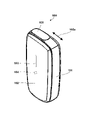
- FIG. 1 shows an example of the appearance of an aerosol generator 100 according to this embodiment.
- the aerosol generator 100 includes, for example, a main body 101, a front panel 102, a display window 103, an operating member 104 and a slider 105.
- the main body 101 is a housing with a predetermined shape, and supports, for example, one or more circuit boards of the aerosol generating device 100 inside.
- the main body 101 has, for example, a rounded rectangular parallelepiped shape that is long in the vertical direction in FIG.
- the size of the main body 101 may be, for example, a size that allows the user to hold it with one hand.
- the front panel 102 is a flexible panel member that covers the front surface of the main body 101.
- the front panel 102 may be detachably coupled to the main body 101 using, for example, magnets.
- a front panel 102 covers an operation member 104 that receives user input.
- the display window 103 is, for example, a strip-shaped window extending in the longitudinal direction at substantially the center of the front panel 102 .
- the display window 103 transmits light emitted by one or more LEDs (Light-Emitting Diodes) arranged between the main body 101 and the front panel 102 to the outside.
- LEDs Light-Emitting Diodes
- the operating member 104 includes physical buttons, for example, and is arranged inside the front panel 102 .
- the operation member 104 detects user input and notifies the control unit 120 of it.
- the case where the operation members 104 composed of physical buttons are covered with the front panel 102 will be described as an example.
- the operation member 104 functions as an operation section in this embodiment.
- the operating member 104 may be a touch-sensitive surface exposed from the front panel, or any other type of input device such as a switch.
- the slider 105 is a cover member slidably disposed on the upper surface of the main body 101 along the direction 105a.
- Slider 105 is configured to open and close an opening into which the aerosol source is inserted. For example, as shown in FIG. 2, when the slider 105 slides forward (in the direction 105a in FIG. 1) (that is, the slider 105 opens), the opening 106 on the upper surface of the main body 101 is exposed.
- the user uses the aerosol generator 100 to inhale the aerosol, the user inserts the tobacco stick 110 into the opening 106 exposed by opening the slider 105 .
- Tobacco stick 110 is inserted from opening 106 into tubular insertion hole 107 along direction 106a.
- a cross section of the insertion hole 107 perpendicular to the axial direction may be, for example, circular, elliptical, or polygonal, and the cross sectional area may be configured to gradually decrease toward the bottom surface.
- the slider 105 also functions as an operation unit in this embodiment.
- the operation member 104 and the slider 105 are used for unlocking operation, which will be described later.
- the operation member 104 may function as the first operation portion
- the slider 105 may function as the second operation portion.
- a tobacco stick 110 is a tobacco article that holds a filler inside a tubular wrapping paper.
- the filling of tobacco stick 110 may be, for example, a mixture of an aerosol-generating substrate and tobacco cuts.
- aerosol-generating substrates substrates containing any type of aerosol source may be used, such as glycerin, propylene glycol, triacetin, 1,3-butanediol, or mixtures thereof.
- Tobacco shreds are so-called flavor sources. Tobacco shredded material may be, for example, laminae or backbones.
- a non-tobacco-derived flavor source may be used instead of tobacco shreds.
- the aerosol generating device 100 includes, for example, a control unit 120, a storage unit 121, an input detection unit 122, a state detection unit 123, a suction detection unit 124, a light emission unit 125, a vibration unit 126, a communication interface (I/F) 127, a connection I /F 128 , heating unit 130 and battery 132 .
- the control unit 120 includes one or more processors and volatile memory, and the processor may be, for example, a CPU (Central Processing Unit) or a microcontroller.
- the control unit 120 loads a computer program (also referred to as software or firmware) stored in the storage unit 121 into a memory and executes it, thereby controlling all functions of the aerosol generation device 100 .
- the storage unit 121 may be, for example, a nonvolatile memory.
- the storage unit 121 stores one or more computer programs, data describing a control sequence (heating profile) for controlling the heating of the heating unit 130, and the like.
- the control unit 120 performs lock release processing, which will be described later, to control unlocking of the aerosol generator.
- the locked state is a state in which the lock function described above (that is, a function that restricts at least part of the user's operations on the operation unit) is activated.
- the control unit 120 controls state transitions of the aerosol generation device 100 described later according to input operations on the operation member 104 and the slider 105 .
- the control unit 120 starts supplying power from the battery 132 to the heating unit 130 when an input operation requesting the start of heating for generating aerosol is detected.
- the input operation here may be, for example, a long press of the operation member 104 detected by the input detection unit 122 .
- the control unit 120 can supply power from the battery 132 to the heating unit 130 .
- the control unit 120 adjusts the duty ratio of control pulses by pulse width modulation (PWM), for example, for temperature control of the heating unit 130 .
- PFM pulse frequency modulation
- the input detection unit 122 is a detection circuit for detecting input operations.
- the input detection unit 122 detects, for example, an input operation on the operation member 104 through pressing of the front panel 102 and outputs an input signal indicating the input operation to the control unit 120 .
- the aerosol generating device 100 may detect pressing of the front panel 102 instead of detecting pressing of the operation member 104 .
- the input detection unit 122 and the state detection unit 123 which will be described later, may function as an operation unit that detects a user's input operation.
- the state detection unit 123 is a detection circuit for detecting the open/closed state of the slider 105, and includes, for example, a Hall element. State detection unit 123 outputs a state detection signal indicating whether slider 105 is open or closed to control unit 120 . Moreover, the state detection unit 123 may be configured to detect the attachment/detachment state of the front panel 102 . State detection unit 123 may include another Hall element for detecting that front panel 102 has been removed, and may output a state detection signal indicating the attachment/detachment state of front panel 102 to control unit 120 .
- the suction detection unit 124 is a detection circuit for detecting suction (puffing) of the tobacco stick 110 by the user.
- suction detection unit 124 may include a thermistor (not shown) disposed near opening 106 .
- the suction detection unit 124 can detect suction based on a change in the resistance value of the thermistor caused by a temperature change caused by the user's suction.
- the suction detection unit 124 may include a pressure sensor (not shown) arranged at the bottom of the insertion hole 107 . In this case, the suction detection unit 124 can detect suction based on a decrease in air pressure caused by airflow caused by suction.
- the suction detection unit 124 outputs, for example, a suction detection signal indicating whether or not suction is being performed to the control unit 120 .
- the light emitting unit 125 includes one or more LEDs and a driver for driving the LEDs.
- Light emitting unit 125 causes each of the LEDs to emit light according to an instruction signal input from control unit 120 .
- Vibrating section 126 includes a vibrator (eg, an eccentric motor) and a driver for driving the vibrator. Vibrating section 126 vibrates the vibrator according to an instruction signal input from control section 120 .
- the control unit 120 controls at least one of the light emitting unit 125 and the vibrating unit 126 in an arbitrary pattern in order to notify the user of some status of the aerosol generating device 100 (for example, a state in which the locked state is released).
- the light emission pattern of the light emitting unit 125 can be distinguished by factors such as the light emission state (lighting/blinking/non-light emission) of each LED, the blinking period, the light emission luminance, and the light emission color.
- the vibration pattern of the vibrating section 126 can be distinguished by factors such as the vibration state (vibration/stop) of the vibrator, the vibration pattern, and the strength of the vibration.
- the communication I/F 127 includes, for example, a communication circuit and an antenna, and is a communication interface for the aerosol generating device 100 to wirelessly communicate with the communication device 200 (for example, a smartphone, personal computer, tablet terminal, etc. owned by the user). .
- the communication I/F 127 is an interface conforming to any wireless communication protocol such as short-range wireless communication such as Bluetooth (registered trademark), near-field wireless communication such as NFC (Near Field Communication), or wireless LAN (Local Area Network). It's okay.
- connection I/F 128 is a wired interface having terminals for connecting the aerosol generating device 100 to other external devices.
- the connection I/F 128 may be a chargeable interface such as a USB (Universal Serial Bus) interface.
- Connection I/F 128 may be used to charge battery 132 from an external power supply (via a power supply line not shown).
- the heating unit 130 may include, for example, a resistive heating component that heats an aerosol source contained in the aerosol-generating substrate of the tobacco stick 110 to generate an aerosol.
- a resistive heating component that heats an aerosol source contained in the aerosol-generating substrate of the tobacco stick 110 to generate an aerosol.
- a mixture of one or more of copper, nickel alloys, chromium alloys, stainless steel, and platinum rhodium may be used as the resistive heating material of the resistive heating component, for example.
- the heating unit 130 is connected to a battery 132 by wiring (not shown).
- the battery 132 is a power source for supplying power to the heating unit 130 and other components of the aerosol generating device 100 .
- Battery 132 may be, for example, a lithium-ion battery.
- the fuel gauge 133 may include, for example, an IC chip for monitoring the remaining power of the battery 132 and other statuses. The fuel gauge 133 periodically measures the status values of the battery 132, for example, the state of charge (SOC), the state of health (SOH), the relative state of charge (RSOC), and the power supply voltage, A measurement result can be output to the control unit 120 .
- the communication device 200 shown in FIG. 3B is, for example, a smartphone, but may be a personal computer, a tablet terminal, or the like. Note that each of the functional blocks described may be integrated or separated. Also, the described functions may be implemented in separate blocks. What is described as hardware may also be implemented in software, and vice versa.
- the communication device 200 includes, for example, a communication interface (I/F) 201, a control unit 202, an input detection unit 203, a sensor unit 204, a display unit 205, a storage unit 206, and a battery 207.
- I/F communication interface
- the communication I/F 201 includes, for example, a communication circuit and the like, and is a communication interface for the communication device 200 to wirelessly communicate with the aerosol generation device 100 and the like.
- the communication I/F 127 is an interface conforming to any wireless communication protocol such as short-range wireless communication such as Bluetooth (registered trademark), near-field wireless communication such as NFC (Near Field Communication), or wireless LAN (Local Area Network). It's okay.
- the communication I/F 201 may further include an interface conforming to a protocol for mobile communication such as LTE, for example, connects to the Internet via mobile communication, and transmits and receives data to and from an external server. may be performed.
- the control unit 202 includes one or more processors and volatile memory, and the processor may be, for example, a CPU (Central Processing Unit).
- the control unit 202 controls all functions of the communication device 200 by loading, for example, a computer program recorded in the storage unit 206 into a memory and executing the program.
- the input detection unit 203 includes buttons and a touch panel provided in the communication device 200, and accepts operations on a setting screen for selecting or setting a heating profile of the aerosol generation device 100 and GUI for various operations.
- the GUI for various operations may include the GUI of a browser application or other applications that display information provided by a server on the network.
- the control unit 202 can transmit information on the heating profile to the aerosol generating device 100 via Bluetooth (registered trademark).
- the GUI for various operations may include a GUI for unlocking the aerosol generating device 100 .
- the control unit 202 transmits a signal to unlock the aerosol generating device 100 .
- the aerosol generation device 100 may release the locked state if the internal state allows the locked state to be released.
- the aerosol generation device 100 can determine that a request from an authenticated (that is, trustworthy) communication device 200 that has been paired with a predetermined procedure is a request from a trustworthy device and release the lock state. .
- the aerosol generating device 100 receives a signal for releasing the locked state from the communication device 200, the aerosol generating device 100 can be unlocked without requesting a further unlocking operation from the user, thereby facilitating the unlocking operation. be able to.
- the sensor unit 204 includes a GPS for identifying the current position of the communication device 200, an imaging sensor for acquiring images or moving images taken around the communication device 200, and biometric authentication for identifying the user of the communication device 200. including sensors for
- the display unit 205 includes a display panel such as an LCD or OLED, and displays GUIs for various operations according to instructions from the control unit 202 .
- the display unit 205 displays, for example, a setting screen for selecting or setting the heating profile of the aerosol generating device 100 described above, and a GUI for various operations such as a GUI for unlocking the aerosol generating device 100.
- the storage unit 206 includes a non-volatile memory such as a semiconductor memory, for example, and stores set user information, computer programs such as applications executed by the control unit 202, and the like.
- the battery 207 includes, for example, a lithium ion battery, and is a power supply for supplying power to each component of the communication device 200.
- power supply lines from battery 132 to each component of communication device 200 are omitted.
- the input operation for releasing the locked state includes an operation of opening the slider 105, an operation of closing the slider 105, an operation of short-pressing (normally pressing) the operating member 104, and an operation of long-pressing the operating member 104.
- FIG. the input operation for releasing the locked state includes a first pressing operation on the operation unit for a predetermined time or less and a second pressing operation on the operation unit for a longer time than the first pressing operation. The user can combine these operations and set them as a series of patterns.
- the aerosol generating device 100 unlocks the aerosol generating device 100 when the input operation input by the user satisfies the operation condition.
- an input operation input by a user satisfies an operation condition
- a case of inputting a series of input operation patterns determined by the user will be described as an example.
- a short press (normal press) operation is, for example, an operation of pressing the operation member 104 for 1000 msec or less
- a long press operation is, for example, an operation of long pressing the operation member 104 for a time longer than 1000 msec. .
- the control unit 120 can identify operations input within a predetermined period of time as a series of pattern operations (also called combination presses). At this time, for example, when a series of patterns determined by the user has been input halfway, if a predetermined time has elapsed, the control unit 120 clears the input halfway. As shown in FIG. 4A, when there is a pressing operation of 1000 ms or less, the control unit 120 identifies the operation as a short pressing (normal pressing). After that, the operating member 104 is released. When the operation member 104 is pressed again, if the release time is, for example, 2000 msec or less, the control unit 120 determines that the previous short press and the next press operation (short press or long press) are performed in a series of patterns. It is judged to be an operation. A series of patterns shown as an example in FIG. 4A shows an operation combining three short presses and one long press.
- the example shown in FIG. 4A shows a case where a series of pattern operations are configured using only operations on the operation member 104.
- the series of pattern operations includes opening and closing of the slider 105. good.
- the control unit 120 may apply the time interval (2000 msec or less) applied to the operation member 104 in order to identify the operation of opening the slider 105 and the operation of closing the slider 105 as a series of pattern operations. Longer time intervals may be applied to the operation of 105 . That is, the time interval between operations may be varied for each operation target.
- the user can set a series of pattern operations for releasing the locked state in the unlock pattern setting mode.
- the controller 120 detects a specific operation while the aerosol generator 100 is being charged (i.e., the USB connector is connected to the connection I/F 128 and power is being supplied), the control unit 120 operates in the unlock pattern setting mode. be able to.
- the specific operation may be, for example, a series of operations such as opening the slider 105, then closing the slider 105, and further pressing the operating member 104 for two seconds.
- the control unit 120 activates the lock function and stores the series of patterns in the storage unit 121. be memorized. In other words, the control unit 120 requests the user to input a series of patterns determined by the user by activating the lock function (putting in a locked state). On the other hand, control unit 120 disables the lock function when a predetermined number of operations (for example, three operations) are not input within a predetermined time in the unlock pattern setting mode. That is, control unit 120 does not request the user to perform an unlocking operation because the lock function is disabled.
- a series of patterns may consist, for example, of up to ten operations. When 10 operations are performed within a predetermined time, or when more than a predetermined number of operations (for example, 3 operations) are performed and a predetermined time elapses, the control unit 120 The unlock pattern setting mode may be terminated.
- input operations on the slider 105 and input operations on the operation member 104 are not distinguished from each other unless otherwise specified, and are simply described as input operations on the operation member 104 .
- a mere “input operation” includes at least one of an input operation on the slider 105 and an input operation on the operation member 104 .
- the control unit 120 discards the input operation and resets the setting to the lock before entering the unlock pattern setting mode. return to state. Furthermore, when the front panel 102 is removed or when the aerosol generating device 100 is paired with a communication device, the control unit 120 detects a specific operation during charging. , the unlock pattern setting mode may not be entered.
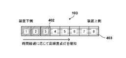
- FIGS. 4BA to 4BC show the eight LEDs visible through the display window 103, with the left side of FIGS. 4BA-4BC corresponding to the bottom side (in FIG. 1) of the aerosol generating device 100, The right side of 4BC corresponds to the top side (in FIG. 1) of the aerosol generator 100.
- FIG. FIG. 4BA schematically shows the state of the light emitting unit 125 when the control unit 120 receives a series of patterns for releasing the locked state. As shown in FIG. 4BA as an example, the control unit 120 does not have to turn on any LEDs when receiving a series of patterns (display state 401 indicates off).
- control unit 120 sets the operating state of the aerosol generating device 100 to a predetermined state (heating control state, charging state, and pairing execution state) in which heating of the heating unit 130 cannot be started. , control is performed not to release the locked state (or not to accept the pattern).
- FIG. 4BB shows the state of the light emitting unit 125 when the input operation is a series of predetermined patterns (that is, when it matches the registered pattern).
- the control unit 120 causes all the LEDs to be baseline lit (the display state 403 indicates baseline lighting). Baseline lighting may be lighting the LED at a luminance of, for example, 5% of the maximum luminance of the LED. After that, the luminance of LED1 to LED8 is changed to normal lighting (the display state 402 is normal lighting).
- the control unit 120 controls the light emission of the eight LEDs one by one for a time period of, for example, 560 ms from the time when the input operation is determined to be a series of predetermined patterns.
- control unit 120 may vibrate for, for example, 560 ms from the time when the input operation is determined to be a series of predetermined patterns. By doing so, the user can be notified visually and tactilely that the locked state is released. In addition, by changing the display state from the baseline lighting to the normal lighting in order, visual changes can be emphasized, and notification can be made more easily noticeable to the user.
- the LED may be illuminated in a manner different from the manner in which the input operation matches a series of patterns (FIG. 4BB). .
- a series of patterns FIG. 4BB
- no display may be performed.
- the aerosol generator 100 can be automatically relocked once the locked state has been released. For example, after releasing the locked state, or after a predetermined period of time (for example, 15 minutes) has elapsed after the completion of the final heating control state described later, the control unit 120 may return to the locked state. At this time, if suction is performed in the heating control state 10 minutes after releasing the locking state, the control unit 120 relocks after a predetermined time (15 minutes) after the heating control state ends. You can
- the aerosol generating device 100 has several operating states, and performs state transitions according to user input and control by the control unit 120 .
- the operating states of the aerosol generating device 100 include, for example, a sleep state 501, an active state 502, and a pairing execution state 503.
- the operating state of the aerosol generating device 100 includes one or more operating states (for example, the heating control state 504 and the heating end state 505) that can transition starting from the active state 502, and one or more operating states that can transition starting from the sleep state 501. It may have one or more operating states (eg, charging state 506).
- the sleep state 501 is, for example, a state in which the operation of the control unit 120 is temporarily stopped to wait in a power saving state in which power consumption is reduced. When the sleep state is canceled, the operation may be resumed from the state before the stop.
- the control unit 120 can accept a predetermined user input, and when the corresponding user input is accepted, the control unit 120 changes the state to a state corresponding to the user input (for example, the active state 502 or the pairing execution state 503). be able to.
- the sleep state may also be referred to as the standby state.
- the sleep state 501 may be entered by a method of "suspend” or “standby” while maintaining the contents of the memory of the control unit 120, or the contents of the memory of the control unit 120 may be stored in the storage unit. 121 and enter the standby state by the method of "hibernation".
- the active state 502 is, for example, a state in which the functions of the device (eg, the aerosol generator 100) are not restricted.
- the functions of the device eg, the aerosol generator 100
- at least the heating function is not restricted.
- the active state may be a state in which the sleep state, which is a power saving state in which power consumption is reduced, is canceled. Note that, in the following description, the active state may also be referred to as the operating state.
- the control unit 120 controls the operating state from the active state 502 (operating state) to the sleep state 501 (standby state) (for example, FIG. 5 512). Further, in the aerosol generating device 100, when the slider 105 is opened in the sleep state 501, the control unit 120 controls the operating state from the sleep state 501 (standby state) to the active state 502 (operating state) (for example, FIG. 5 511).
- the pairing execution state 503 is a state for executing pairing between the communication device 200 and Bluetooth (registered trademark).
- the control unit 120 shifts the state to the pairing execution state (for example, 513 in FIG. 5) when a predetermined input operation on the operation member 104 is detected while the slider 105 is closed.
- pairing also referred to as initial setting
- the control unit 120 registers the paired device in the whitelist held in the storage unit 121 .
- the control unit 120 returns the operating state from the pairing execution state 503 to the sleep state 501 .
- control unit 120 transitions the operation state to a heating control state 504 for exerting a heating function (for example, generating an aerosol) (for example, the state shown in FIG. 5). 515). Control unit 120 may then transition the operating state to active state 502 .
- a heating control state 504 for exerting a heating function (for example, generating an aerosol) (for example, the state shown in FIG. 5). 515). Control unit 120 may then transition the operating state to active state 502 .
- control unit 120 may cause the operating state to transition from the sleep state 501 to the state of charging the aerosol generating device (eg, 506) in response to the USB terminal being connected to the connection I/F 128. Good (eg, 516 in FIG. 5).
- the control unit 120 detects an input operation via the input detection unit 122 and the state detection unit 123.
- the control unit 120 determines whether the aerosol generating device 100 is in the locked state. For example, the control unit 120 holds information indicating the locked state by a predetermined method such as a flag when the lock function is enabled or disabled, and based on the held information indicating the locked state, the lock state is changed. judge.
- the control unit 120 advances the process to S603. Otherwise, the controller 120 terminates the series of operations of this process because it is not necessary to release the locked state. In this case, the control unit 120 may accept the input operation as it is after the end of this process.
- the control unit 120 acquires the operating state of the aerosol generating device 100.
- the control unit 120 may acquire the operating state via each unit such as the state detecting unit 123, and store information indicating the operating state of the device in the memory or the storage unit 121 each time the operating state changes. . Then, when acquiring the operating state, the control unit 120 refers to the information indicating the operating state stored in the memory or the storage unit 121, and acquires the operating state that the aerosol generating device 100 is in the charging state. You can do
- the control unit 120 determines whether the operating state of the aerosol generating device 100 is such that the heating unit 130 cannot start heating. For example, the control unit 120 determines whether the operating state of the aerosol generating device 100 is a state for performing pairing (that is, a state in which initial settings for short-range wireless communication are being performed). When the operating state of the aerosol generating device 100 is the pairing execution state, the control unit 120 determines that the heating of the heating unit 130 cannot be started, ends this series of operations, and otherwise ends the operation. If so, the process proceeds to S605.
- a state for performing pairing that is, a state in which initial settings for short-range wireless communication are being performed.
- control unit 120 determines whether the operating state of the aerosol generating device 100 is the charging state. When the operating state of the aerosol generating device 100 is the charging state, the control unit 120 determines that the heating unit 130 cannot start heating, and terminates this series of operations. , the process may proceed to S605.
- control unit 120 determines whether the operating state of the aerosol generating device 100 is the heating control state. When the operating state of the aerosol generating device 100 is the heating control state, the control unit 120 determines that the heating of the heating unit 130 cannot be started, terminates this series of operations, and otherwise may advance the process to S605.
- control unit 120 determines whether the front panel 102 is removed, and if the front panel 102 is removed, determines that the heating unit 130 cannot start heating, and terminates this series of operations, Otherwise, the process may proceed to S605.
- the lock can be released only when the aerosol generating device 100 is being used in an appropriate state, and then the heating unit 130 can be heated.
- control unit 120 may determine whether the remaining battery level is less than a predetermined threshold value based on the signal from the remaining battery level gauge 133 . That is, the control unit 120 may determine that the heating unit 130 cannot start heating when the remaining battery charge is less than a predetermined threshold. Considering the remaining battery capacity in this way can prevent a deterioration in the user experience such as running out of power when the user starts to inhale the aerosol.
- control unit 120 does not accept an input operation after the operating state becomes a state in which heating cannot be started. At this time, control unit 120 discards the input operation received before the operating state becomes a state in which heating cannot be started.
- the control unit 120 accepts an input operation to the operation unit. In this way, the control unit 120 executes S604 first and does not accept an input operation in a state in which heating cannot be started. occurrence can be prevented.
- the control unit 120 temporarily stores the received input operation in the memory of the control unit 120, for example. In this case, the memory stores a series of input operations that have been accepted so far.
- the control unit 120 determines whether the number of received input operations is greater than or equal to the number of operations in a series of patterns set for unlocking. For example, the control unit 120 controls the number of received input operations (for example, 6) and the number of operations in a series of patterns set for unlocking (for example, a preset "5 short presses + 1 long press"). push"). If the control unit 120 determines that the number of received input operations is equal to or greater than the number of operations of the series of patterns set for unlocking, the process proceeds to S607. Otherwise (that is, the number of input operations is less than the number of lock release setting operations), the control unit 120 returns the process to S601 in order to receive further input.
- the control unit 120 determines whether the number of received input operations is greater than or equal to the number of operations in a series of patterns set for unlocking. For example, the control unit 120 controls the number of received input operations (for example, 6) and the number of operations in a series of patterns set for unlocking (for example, a preset "5 short presse
- the control unit 120 determines whether the input operation constitutes a series of predetermined patterns. For example, the control unit 120 can perform a series of input operations (for example, “5 short presses + 1 long press”) stored in the memory and a series of operation patterns set for unlocking. The number (for example, "5 short presses + 1 long press” set in advance) is compared. If both match, the control unit 120 determines that the input operation forms a predetermined series of patterns, and advances the process to S608. Otherwise, control unit 120 determines that the received input operation does not match the release pattern (is not correct input), and terminates this series of processes.
- a series of input operations for example, “5 short presses + 1 long press” stored in the memory and a series of operation patterns set for unlocking. The number (for example, "5 short presses + 1 long press” set in advance) is compared. If both match, the control unit 120 determines that the input operation forms a predetermined series of patterns, and advances the process to S608. Otherwise, control unit 120 determines that the received
- control unit 120 unlocks the aerosol generating device 100. Then, in S609, for example, as described with reference to FIG. 4B, the LED is turned on and the vibration is driven. When the lighting of the LED and the driving of the vibration in S609 are completed, the control unit 120 completes this series of processing.
- the control unit 120 cancels the locked state of the aerosol generation device in response to determining that the input operation constitutes a series of patterns defined (set) by the user. made it At this time, if the operating state of the aerosol generating device is such that the heating of the heating unit 130 cannot be started (described above in S604), the locked state is not released. By doing so, it becomes possible to unlock the aerosol generator at an appropriate timing.
- the control unit 120 executes the processing of S601 and S602 in the same manner as the operation of FIG. 6 described above, and advances the processing to S701 when the aerosol generating device 100 is in the locked state. If the aerosol generating device 100 is not in the locked state, it is not necessary to release the locked state, so the control unit 120 terminates the series of operations of this process. In this case, the control unit 120 may accept the input operation as it is after the end of this process.
- the control unit 120 determines whether the input operation corresponds to the default operation.
- the default operation is, for example, a predetermined operation (for example, three short presses and one long press on the operation unit) for executing Bluetooth (registered trademark) pairing. If the input operation so far corresponds to a series of patterns forming the default operation (for example, the input operation so far is two short presses), the control unit 120 executes the function assigned to the default operation. To do so, an input is accepted at S605 (without making the determinations of S603 and S604). In other words, when the input operation corresponds to a series of default operation patterns, control unit 120 prioritizes the function assigned to the default operation over the unlock pattern set by the user. can be executed.
- the control unit 120 determines whether the received input operation constitutes a series of patterns of default operations. When the received input operation constitutes a series of predetermined operation patterns (for example, three short presses and one long press for pairing), the control unit 120 cancels the lock state and preferentially To execute pairing, the process proceeds to S608. If the received input operation does not constitute a series of default operation patterns, the control unit 120 executes the processes of S606 and S607 shown in FIG. 6 (unlock process). After that, the control unit 120 executes the processes of S608 and S609 in the same manner as described above, and ends this series of processes.
- a series of predetermined operation patterns for example, three short presses and one long press for pairing
- the control unit 120 cancels the lock state and preferentially To execute pairing, the process proceeds to S608. If the received input operation does not constitute a series of default operation patterns, the control unit 120 executes the processes of S606 and S607 shown in FIG. 6 (unlock process). After that, the control unit 120 executes the processes
- the default operation when a default operation is registered in the aerosol generating device 100, the default operation can be preferentially executed. Then, while giving priority to the predetermined operation, if the operating state of the aerosol generating device is a state in which the heating of the heating unit 130 cannot be started (described above in S604), the locked state can be prevented from being released. can. That is, it is possible to unlock the aerosol generator at an appropriate timing.
- the operation member 104 may be a touch panel exposed from the front panel 102 .
- the input operation may include a tap operation on the touch panel and a flick operation along the surface of the touch panel.
- the user may configure a series of patterns for unlocking by combining a tap operation on the touch panel and a flick operation on the touch panel.
- the control unit 120 accepts an input operation and unlocks the locked state has been described as an example.
- the above-described embodiments can be applied when receiving a signal to release the locked state transmitted via Bluetooth from a paired communication device in order to release the locked state. can. That is, the control unit 120 may unlock the aerosol generating device 100 in response to receiving a signal for unlocking from the paired communication device. At this time, the control unit 120 is configured not to unlock the locked state when the operating state of the aerosol generating device 100 is the predetermined state (described above) in which the heating of the heating unit 130 cannot be started. . Also in this way, the aerosol generator can be unlocked at an appropriate timing.
Landscapes
- Engineering & Computer Science (AREA)
- Human Computer Interaction (AREA)
- General Engineering & Computer Science (AREA)
- Theoretical Computer Science (AREA)
- Computer Networks & Wireless Communication (AREA)
- Physics & Mathematics (AREA)
- General Physics & Mathematics (AREA)
- Containers And Packaging Bodies Having A Special Means To Remove Contents (AREA)
Abstract
Description
ユーザによる入力操作を検知する操作部と、
エアロゾル源を霧化させる加熱手段と、
前記入力操作がユーザによって定められた操作条件を満たしたことに応じて、前記エアロゾル生成装置に対するロック状態を解除する制御手段と、を有し、
前記制御手段は、前記エアロゾル生成装置の動作状態が前記加熱手段の加熱を開始することができない所定の状態である場合には、前記ロック状態を解除しない、エアロゾル生成装置が提供される。
前記所定の状態は、前記電源を充電している状態を含んでよい。
前記所定の状態は、前記電源のバッテリ残量が所定値未満である状態を含んでよい。
前記所定の状態は、前記外部の通信装置との間で前記近距離無線通信の初期設定を行っている状態を含んでよい。
前記制御手段は、前記近距離無線通信の初期設定を行った前記外部の通信装置からロック状態を解除する信号を受信することにより、前記エアロゾル生成装置に対するロック状態を解除可能であってよい。
前記所定の状態は、前記パネルが前記エアロゾル生成装置から取り外された状態を含んでよい。
前記入力操作は、前記タッチパネルに対するタップ操作と、前記タッチパネルの面に沿うフリック操作とを含んでよい。
前記エアロゾル生成装置との間で予め近距離無線通信の初期設定が行われた通信装置からロック状態を解除する信号を受信する通信手段と、
エアロゾル源を霧化させる加熱手段と、
前記ロック状態を解除する信号を受信したことに応じて、前記エアロゾル生成装置に対するロック状態を解除する制御手段と、を有し、
前記制御手段は、前記エアロゾル生成装置の動作状態が前記加熱手段の加熱を開始することができない所定の状態である場合には、前記ロック状態を解除しない、エアロゾル生成装置が提供される。
本発明のその他の特徴及び利点は、添付図面を参照とした以下の説明により明らかになるであろう。なお、添付図面においては、同じ若しくは同様の構成には、同じ参照番号を付す。
以下の説明では、ユーザによる操作部に対する操作のうちの少なくとも一部の操作を制限するロック機能を有するエアロゾル生成装置を例に説明する。
図1は、本実施形態に係るエアロゾル生成装置100の外観の一例を示している。エアロゾル生成装置100は、例えば、本体101、前面パネル102、表示窓103、操作部材104及びスライダ105を含む。
次に、図3Aを参照して、エアロゾル生成装置100の機能構成例について説明する。なお、説明する機能ブロックの各々は、統合されまたは分離されてもよい。また、説明する機能が別のブロックで実現されてもよい。ハードウェアとして説明するものがソフトウェアで実現されてもよく、その逆であってもよい。
次に、通信装置200の簡略的な構成例について、図3Bを参照して説明する。図3Bに示す通信装置200は、例えばスマートフォンであるが、パーソナルコンピュータやタブレット端末などであってもよい。なお、説明する機能ブロックの各々は、統合されまたは分離されてもよい。また説明する機能が別のブロックで実現されてもよい。ハードウェアとして説明するものがソフトウェアで実現されてもよく、その逆であってもよい。
エアロゾル生成装置100のロック状態を解除するための、入力操作について説明する。ロック状態を解除するための入力操作は、スライダ105を開ける操作、スライダ105を閉じる操作、操作部材104を短押し(通常押し)する操作、及び操作部材104を長押しする操作を含む。換言すれば、ロック状態を解除するための入力操作は、操作部に対する所定時間以下の第1押下操作と、操作部に対する、第1押下操作より長い時間の第2押下操作とを含む。ユーザは、これらの操作を組み合わせて、一連のパターンとして設定することができる。エアロゾル生成装置100は、ユーザによって入力される入力操作が操作条件を満たす場合に、エアロゾル生成装置100のロック状態を解除する。以下で説明する実施形態では、ユーザによって入力される入力操作が操作条件を満たす場合として、例えば、ユーザが定めた入力操作の一連のパターンを入力する場合を例に説明する。
エアロゾル生成装置100の状態遷移の一例について、図5を参照して説明する。エアロゾル生成装置100は、いくつかの動作状態を有し、ユーザによる入力や制御部120の制御に応じて、状態遷移を行う。エアロゾル生成装置100の動作状態は、例えば、スリープ状態501、アクティブ状態502、ペアリング実行用状態503を含む。また、エアロゾル生成装置100の動作状態は、アクティブ状態502を起点として遷移可能な1つ以上の動作状態(例えば加熱制御状態504及び加熱終了状態505)、及びスリープ状態501を起点として遷移可能な1つ以上の動作状態(例えば充電状態506)を有してよい。
次に、エアロゾル生成装置100において実行される、ロック解除処理の一連の動作について、図6を参照して説明する。なお、本処理は、制御部120のプロセッサが記憶部121に記憶されるプログラムを実行することにより実現される。以下の説明では、ユーザがロック状態を解除するための、一連の入力を1つずつ入力するものとする。
次に、エアロゾル生成装置100において実行される、ロック解除処理の他の例について、図7A及び図7Bを参照して説明する。本処理では、図6を参照して上述したロック解除処理の動作に加えて、他の機能に割り当てられている予め定められた操作(既定操作という)を優先的に受け付ける。なお、本処理は、制御部120のプロセッサが記憶部121に記憶されるプログラムを実行することにより実現される。以下の説明では、図6と同一又は実質的に同一である動作については同一の参照符号を付して重複する説明は省略する。
Claims (18)
- エアロゾル生成装置であって
ユーザによる入力操作を検知する操作部と、
エアロゾル源を霧化させる加熱手段と、
前記入力操作がユーザによって定められた操作条件を満たしたことに応じて、前記エアロゾル生成装置に対するロック状態を解除する制御手段と、を有し、
前記制御手段は、前記エアロゾル生成装置の動作状態が前記加熱手段の加熱を開始することができない所定の状態である場合には、前記ロック状態を解除しない、エアロゾル生成装置。 - 前記制御手段は、前記入力操作が開始されたときに前記動作状態が前記所定の状態である場合、前記入力操作を受け付けない、請求項1に記載のエアロゾル生成装置。
- 前記制御手段は、前記入力操作が開始された後であり、且つ当該入力操作が前記ユーザによって定められた操作条件を満たす前に、前記動作状態が前記所定の状態となった場合、前記動作状態が前記所定の状態となった後の前記入力操作を受け付けない、請求項1又は2に記載のエアロゾル生成装置。
- 前記制御手段は、前記動作状態が前記所定の状態となる前に受け付けた前記入力操作を破棄する、請求項3に記載のエアロゾル生成装置。
- 充電可能な電源を更に含み、
前記所定の状態は、前記電源を充電している状態を含む、請求項1から4のいずれか1項に記載のエアロゾル生成装置。 - 充電可能な電源を更に含み、
前記所定の状態は、前記電源のバッテリ残量が所定値未満である状態を含む、請求項1から4のいずれか1項に記載のエアロゾル生成装置。 - 外部の通信装置と近距離無線通信が可能である通信手段を更に含み、
前記所定の状態は、前記外部の通信装置との間で前記近距離無線通信の初期設定を行っている状態を含む、請求項1から6のいずれか1項に記載のエアロゾル生成装置。 - 外部の通信装置と近距離無線通信が可能である通信手段を更に含み、
前記制御手段は、前記近距離無線通信の初期設定を行った前記外部の通信装置からロック状態を解除する信号を受信することにより、前記エアロゾル生成装置に対するロック状態を解除可能である、請求項1から6のいずれか1項に記載のエアロゾル生成装置。 - 前記所定の状態は、前記加熱手段に対する加熱制御を行っている状態を更に含む、請求項1から8のいずれか1項に記載のエアロゾル生成装置。
- 前記エアロゾル生成装置に着脱可能に構成されるパネルを更に含み、
前記所定の状態は、前記パネルが前記エアロゾル生成装置から取り外された状態を含む、請求項1から9のいずれか1項に記載のエアロゾル生成装置。 - 前記入力操作は、第1操作部に対する入力装置と、前記第1操作部と異なる第2操作部に対する入力操作とを含む、請求項1から10のいずれか1項に記載のエアロゾル生成装置。
- 前記入力操作は、前記操作部に対する所定時間以下の第1押下操作と、同一の前記操作部に対する、前記第1押下操作より長い時間の第2押下操作とを含む、請求項1から10のいずれか1項に記載のエアロゾル生成装置。
- 前記操作部はタッチパネルで構成され、
前記入力操作は、前記タッチパネルに対するタップ操作と、前記タッチパネルの面に沿うフリック操作とを含む、請求項1から10のいずれか1項に記載のエアロゾル生成装置。 - 前記制御手段は、前記入力操作が、予め設定された操作条件に対応する場合、前記ユーザによって定められた操作条件よりも優先して、前記予め設定された操作条件に対応する機能を実行する、請求項1から13のいずれか1項に記載のエアロゾル生成装置。
- エアロゾル生成装置であって
前記エアロゾル生成装置との間で予め近距離無線通信の初期設定が行われた通信装置からロック状態を解除する信号を受信する通信手段と、
エアロゾル源を霧化させる加熱手段と、
前記ロック状態を解除する信号を受信したことに応じて、前記エアロゾル生成装置に対するロック状態を解除する制御手段と、を有し、
前記制御手段は、前記エアロゾル生成装置の動作状態が前記加熱手段の加熱を開始することができない所定の状態である場合には、前記ロック状態を解除しない、エアロゾル生成装置。 - プロセッサを、請求項1から15のいずれか1項に記載のエアロゾル生成装置の制御手段として機能させるためのプログラム。
- エアロゾル生成装置の制御方法であって、
ユーザによる入力操作を検知することと、
前記エアロゾル生成装置の動作状態がエアロゾル源を霧化させる加熱手段の加熱を開始することができない所定の状態であるかを判定することと、
前記入力操作がユーザによって定められた操作条件を満たしたことに応じて、前記エアロゾル生成装置に対するロック状態を解除することと、を有し、
前記動作状態が前記所定の状態である場合には、前記ロック状態を解除しない、エアロゾル生成装置の制御方法。 - エアロゾル生成装置の制御方法であって、
前記エアロゾル生成装置との間で予め近距離無線通信の初期設定が行われた通信装置からロック状態を解除する信号を受信することと、
前記エアロゾル生成装置の動作状態がエアロゾル源を霧化させる加熱手段の加熱を開始することができない所定の状態であるかを判定することと、
前記ロック状態を解除する信号を受信したことに応じて、前記エアロゾル生成装置に対するロック状態を解除することと、を有し、
前記動作状態が前記所定の状態である場合には、前記ロック状態を解除しない、エアロゾル生成装置の制御方法。
Priority Applications (5)
| Application Number | Priority Date | Filing Date | Title |
|---|---|---|---|
| JP2023517100A JP7684390B2 (ja) | 2021-04-28 | 2022-02-28 | エアロゾル生成装置、エアロゾル生成装置の制御方法、及びプログラム |
| EP22795271.0A EP4331403A4 (en) | 2021-04-28 | 2022-02-28 | AEROSOL GENERATING DEVICE, AEROSOL GENERATING DEVICE CONTROL METHOD, AND PROGRAM |
| KR1020237039477A KR20230172556A (ko) | 2021-04-28 | 2022-02-28 | 에어로졸 생성 장치, 에어로졸 생성 장치의 제어 방법, 및 프로그램 |
| CN202280030866.XA CN117202811A (zh) | 2021-04-28 | 2022-02-28 | 气溶胶生成装置、气溶胶生成装置的控制方法以及程序 |
| US18/493,825 US20240049803A1 (en) | 2021-04-28 | 2023-10-25 | Aerosol generating apparatus, control method of aerosol generating apparatus, and storage medium |
Applications Claiming Priority (2)
| Application Number | Priority Date | Filing Date | Title |
|---|---|---|---|
| JP2021-076013 | 2021-04-28 | ||
| JP2021076013 | 2021-04-28 |
Related Child Applications (1)
| Application Number | Title | Priority Date | Filing Date |
|---|---|---|---|
| US18/493,825 Continuation US20240049803A1 (en) | 2021-04-28 | 2023-10-25 | Aerosol generating apparatus, control method of aerosol generating apparatus, and storage medium |
Publications (1)
| Publication Number | Publication Date |
|---|---|
| WO2022230348A1 true WO2022230348A1 (ja) | 2022-11-03 |
Family
ID=83846904
Family Applications (1)
| Application Number | Title | Priority Date | Filing Date |
|---|---|---|---|
| PCT/JP2022/008331 Ceased WO2022230348A1 (ja) | 2021-04-28 | 2022-02-28 | エアロゾル生成装置、エアロゾル生成装置の制御方法、及びプログラム |
Country Status (6)
| Country | Link |
|---|---|
| US (1) | US20240049803A1 (ja) |
| EP (1) | EP4331403A4 (ja) |
| JP (1) | JP7684390B2 (ja) |
| KR (1) | KR20230172556A (ja) |
| CN (1) | CN117202811A (ja) |
| WO (1) | WO2022230348A1 (ja) |
Cited By (1)
| Publication number | Priority date | Publication date | Assignee | Title |
|---|---|---|---|---|
| WO2024231284A1 (en) | 2023-05-10 | 2024-11-14 | Jt International Sa | Aerosol-generating device |
Families Citing this family (1)
| Publication number | Priority date | Publication date | Assignee | Title |
|---|---|---|---|---|
| EP4649844A1 (en) * | 2024-05-17 | 2025-11-19 | Imperial Tobacco Limited | Aerosol-generating apparatus and methods relating to the same |
Citations (4)
| Publication number | Priority date | Publication date | Assignee | Title |
|---|---|---|---|---|
| JP2019521739A (ja) * | 2016-05-25 | 2019-08-08 | ジュール・ラブズ・インコーポレイテッドJuul Labs, Inc. | 電子気化器の制御 |
| JP2020080654A (ja) | 2018-11-15 | 2020-06-04 | 株式会社ジャパンディスプレイ | 吸引装置及び情報処理システム |
| WO2020193194A1 (en) * | 2019-03-22 | 2020-10-01 | Nerudia Limited | Smoking substitute system |
| JP2021076013A (ja) | 2021-02-19 | 2021-05-20 | 三協立山株式会社 | カーテンウォール |
Family Cites Families (7)
| Publication number | Priority date | Publication date | Assignee | Title |
|---|---|---|---|---|
| US20180132528A1 (en) * | 2016-11-14 | 2018-05-17 | Rai Strategic Holdings, Inc. | Photoelectric proximity sensor for gesture-based control of an aerosol delivery device |
| WO2018191911A1 (zh) * | 2017-04-20 | 2018-10-25 | 深圳麦克韦尔股份有限公司 | 电子烟及其解锁方法 |
| EP4579498A3 (en) * | 2017-12-21 | 2025-08-20 | Juul Labs, Inc. | Vaporizer controls |
| US20200000143A1 (en) * | 2018-06-27 | 2020-01-02 | Juul Labs, Inc. | Connected vaporizer device systems |
| KR102156840B1 (ko) | 2018-12-27 | 2020-09-16 | 주식회사 원방테크 | 국부 드라이룸 시스템 |
| KR102255922B1 (ko) * | 2019-03-22 | 2021-05-25 | 주식회사 케이티앤지 | 에어로졸 생성 장치의 잠금 모드를 해제하는 방법 및 그 에어로졸 생성 장치 |
| US11200770B2 (en) * | 2019-04-02 | 2021-12-14 | Rai Strategic Holdings, Inc. | Functional control and age verification of electronic devices through visual communication |
-
2022
- 2022-02-28 WO PCT/JP2022/008331 patent/WO2022230348A1/ja not_active Ceased
- 2022-02-28 JP JP2023517100A patent/JP7684390B2/ja active Active
- 2022-02-28 CN CN202280030866.XA patent/CN117202811A/zh active Pending
- 2022-02-28 KR KR1020237039477A patent/KR20230172556A/ko active Pending
- 2022-02-28 EP EP22795271.0A patent/EP4331403A4/en active Pending
-
2023
- 2023-10-25 US US18/493,825 patent/US20240049803A1/en active Pending
Patent Citations (4)
| Publication number | Priority date | Publication date | Assignee | Title |
|---|---|---|---|---|
| JP2019521739A (ja) * | 2016-05-25 | 2019-08-08 | ジュール・ラブズ・インコーポレイテッドJuul Labs, Inc. | 電子気化器の制御 |
| JP2020080654A (ja) | 2018-11-15 | 2020-06-04 | 株式会社ジャパンディスプレイ | 吸引装置及び情報処理システム |
| WO2020193194A1 (en) * | 2019-03-22 | 2020-10-01 | Nerudia Limited | Smoking substitute system |
| JP2021076013A (ja) | 2021-02-19 | 2021-05-20 | 三協立山株式会社 | カーテンウォール |
Non-Patent Citations (1)
| Title |
|---|
| See also references of EP4331403A4 |
Cited By (1)
| Publication number | Priority date | Publication date | Assignee | Title |
|---|---|---|---|---|
| WO2024231284A1 (en) | 2023-05-10 | 2024-11-14 | Jt International Sa | Aerosol-generating device |
Also Published As
| Publication number | Publication date |
|---|---|
| US20240049803A1 (en) | 2024-02-15 |
| JP7684390B2 (ja) | 2025-05-27 |
| EP4331403A4 (en) | 2025-05-07 |
| KR20230172556A (ko) | 2023-12-22 |
| JPWO2022230348A1 (ja) | 2022-11-03 |
| EP4331403A1 (en) | 2024-03-06 |
| CN117202811A (zh) | 2023-12-08 |
Similar Documents
| Publication | Publication Date | Title |
|---|---|---|
| EP4331408A1 (en) | Power unit for inhaler | |
| WO2022230348A1 (ja) | エアロゾル生成装置、エアロゾル生成装置の制御方法、及びプログラム | |
| WO2022230322A1 (ja) | エアロゾル生成装置、制御方法及びコンピュータプログラム | |
| JP2025170341A (ja) | エアロゾル生成装置、エアロゾル生成装置の制御方法、及びプログラム | |
| WO2022230232A1 (ja) | 表示装置、吸引装置、表示方法、及びプログラム | |
| JP7830604B2 (ja) | 吸引器用の電源ユニット | |
| WO2023197741A1 (zh) | 气溶胶生成装置及其控制方法和装置、计算机存储介质 | |
| JP7678809B2 (ja) | 無線通信インターフェースを有するエアロゾル発生装置 | |
| JP7544966B2 (ja) | 電子デバイス及び電子デバイスの制御方法 | |
| EA048079B1 (ru) | Устройство генерации аэрозоля, способ управления устройством генерации аэрозоля и программа | |
| KR102960417B1 (ko) | 흡인기용의 전원 유닛 | |
| EP4573945A1 (en) | Inhalation device, control method, and program | |
| US20250089807A1 (en) | Flavor inhaler or aerosol generation device, and operation method and program for same | |
| EA048460B1 (ru) | Блок питания для ингалятора | |
| CN120302906A (zh) | 吸入装置、控制方法和程序 | |
| EA051686B1 (ru) | Блок питания для ингалятора | |
| CN119630303A (zh) | 气溶胶生成系统、控制方法以及程序 | |
| CN119604203A (zh) | 气溶胶生成系统、控制方法以及程序 |
Legal Events
| Date | Code | Title | Description |
|---|---|---|---|
| 121 | Ep: the epo has been informed by wipo that ep was designated in this application |
Ref document number: 22795271 Country of ref document: EP Kind code of ref document: A1 |
|
| WWE | Wipo information: entry into national phase |
Ref document number: 2023517100 Country of ref document: JP |
|
| WWE | Wipo information: entry into national phase |
Ref document number: 202280030866.X Country of ref document: CN |
|
| ENP | Entry into the national phase |
Ref document number: 20237039477 Country of ref document: KR Kind code of ref document: A |
|
| WWE | Wipo information: entry into national phase |
Ref document number: 1020237039477 Country of ref document: KR |
|
| WWE | Wipo information: entry into national phase |
Ref document number: 2022795271 Country of ref document: EP |
|
| NENP | Non-entry into the national phase |
Ref country code: DE |
|
| ENP | Entry into the national phase |
Ref document number: 2022795271 Country of ref document: EP Effective date: 20231128 |