WO2022230515A1 - 空調パネル - Google Patents
空調パネル Download PDFInfo
- Publication number
- WO2022230515A1 WO2022230515A1 PCT/JP2022/014718 JP2022014718W WO2022230515A1 WO 2022230515 A1 WO2022230515 A1 WO 2022230515A1 JP 2022014718 W JP2022014718 W JP 2022014718W WO 2022230515 A1 WO2022230515 A1 WO 2022230515A1
- Authority
- WO
- WIPO (PCT)
- Prior art keywords
- panel
- condenser
- vapor refrigerant
- evaporator
- absorber
- Prior art date
- Legal status (The legal status is an assumption and is not a legal conclusion. Google has not performed a legal analysis and makes no representation as to the accuracy of the status listed.)
- Ceased
Links
Images

Classifications
-
- F—MECHANICAL ENGINEERING; LIGHTING; HEATING; WEAPONS; BLASTING
- F24—HEATING; RANGES; VENTILATING
- F24F—AIR-CONDITIONING; AIR-HUMIDIFICATION; VENTILATION; USE OF AIR CURRENTS FOR SCREENING
- F24F5/00—Air-conditioning systems or apparatus not covered by F24F1/00 or F24F3/00, e.g. using solar heat or combined with household units such as an oven or water heater
- F24F5/0007—Air-conditioning systems or apparatus not covered by F24F1/00 or F24F3/00, e.g. using solar heat or combined with household units such as an oven or water heater cooling apparatus specially adapted for use in air-conditioning
- F24F5/0014—Air-conditioning systems or apparatus not covered by F24F1/00 or F24F3/00, e.g. using solar heat or combined with household units such as an oven or water heater cooling apparatus specially adapted for use in air-conditioning using absorption or desorption
-
- F—MECHANICAL ENGINEERING; LIGHTING; HEATING; WEAPONS; BLASTING
- F25—REFRIGERATION OR COOLING; COMBINED HEATING AND REFRIGERATION SYSTEMS; HEAT PUMP SYSTEMS; MANUFACTURE OR STORAGE OF ICE; LIQUEFACTION SOLIDIFICATION OF GASES
- F25B—REFRIGERATION MACHINES, PLANTS OR SYSTEMS; COMBINED HEATING AND REFRIGERATION SYSTEMS; HEAT PUMP SYSTEMS
- F25B17/00—Sorption machines, plants or systems, operating intermittently, e.g. absorption or adsorption type
- F25B17/08—Sorption machines, plants or systems, operating intermittently, e.g. absorption or adsorption type the absorbent or adsorbent being a solid, e.g. salt
-
- F—MECHANICAL ENGINEERING; LIGHTING; HEATING; WEAPONS; BLASTING
- F25—REFRIGERATION OR COOLING; COMBINED HEATING AND REFRIGERATION SYSTEMS; HEAT PUMP SYSTEMS; MANUFACTURE OR STORAGE OF ICE; LIQUEFACTION SOLIDIFICATION OF GASES
- F25B—REFRIGERATION MACHINES, PLANTS OR SYSTEMS; COMBINED HEATING AND REFRIGERATION SYSTEMS; HEAT PUMP SYSTEMS
- F25B27/00—Machines, plants or systems, using particular sources of energy
- F25B27/002—Machines, plants or systems, using particular sources of energy using solar energy
- F25B27/007—Machines, plants or systems, using particular sources of energy using solar energy in sorption type systems
-
- F—MECHANICAL ENGINEERING; LIGHTING; HEATING; WEAPONS; BLASTING
- F24—HEATING; RANGES; VENTILATING
- F24F—AIR-CONDITIONING; AIR-HUMIDIFICATION; VENTILATION; USE OF AIR CURRENTS FOR SCREENING
- F24F5/00—Air-conditioning systems or apparatus not covered by F24F1/00 or F24F3/00, e.g. using solar heat or combined with household units such as an oven or water heater
- F24F5/0046—Air-conditioning systems or apparatus not covered by F24F1/00 or F24F3/00, e.g. using solar heat or combined with household units such as an oven or water heater using natural energy, e.g. solar energy, energy from the ground
- F24F2005/0064—Air-conditioning systems or apparatus not covered by F24F1/00 or F24F3/00, e.g. using solar heat or combined with household units such as an oven or water heater using natural energy, e.g. solar energy, energy from the ground using solar energy
-
- F—MECHANICAL ENGINEERING; LIGHTING; HEATING; WEAPONS; BLASTING
- F24—HEATING; RANGES; VENTILATING
- F24F—AIR-CONDITIONING; AIR-HUMIDIFICATION; VENTILATION; USE OF AIR CURRENTS FOR SCREENING
- F24F5/00—Air-conditioning systems or apparatus not covered by F24F1/00 or F24F3/00, e.g. using solar heat or combined with household units such as an oven or water heater
- F24F5/0007—Air-conditioning systems or apparatus not covered by F24F1/00 or F24F3/00, e.g. using solar heat or combined with household units such as an oven or water heater cooling apparatus specially adapted for use in air-conditioning
- F24F5/0017—Air-conditioning systems or apparatus not covered by F24F1/00 or F24F3/00, e.g. using solar heat or combined with household units such as an oven or water heater cooling apparatus specially adapted for use in air-conditioning using cold storage bodies, e.g. ice
- F24F5/0021—Air-conditioning systems or apparatus not covered by F24F1/00 or F24F3/00, e.g. using solar heat or combined with household units such as an oven or water heater cooling apparatus specially adapted for use in air-conditioning using cold storage bodies, e.g. ice using phase change material [PCM] for storage
-
- Y—GENERAL TAGGING OF NEW TECHNOLOGICAL DEVELOPMENTS; GENERAL TAGGING OF CROSS-SECTIONAL TECHNOLOGIES SPANNING OVER SEVERAL SECTIONS OF THE IPC; TECHNICAL SUBJECTS COVERED BY FORMER USPC CROSS-REFERENCE ART COLLECTIONS [XRACs] AND DIGESTS
- Y02—TECHNOLOGIES OR APPLICATIONS FOR MITIGATION OR ADAPTATION AGAINST CLIMATE CHANGE
- Y02A—TECHNOLOGIES FOR ADAPTATION TO CLIMATE CHANGE
- Y02A30/00—Adapting or protecting infrastructure or their operation
- Y02A30/27—Relating to heating, ventilation or air conditioning [HVAC] technologies
-
- Y—GENERAL TAGGING OF NEW TECHNOLOGICAL DEVELOPMENTS; GENERAL TAGGING OF CROSS-SECTIONAL TECHNOLOGIES SPANNING OVER SEVERAL SECTIONS OF THE IPC; TECHNICAL SUBJECTS COVERED BY FORMER USPC CROSS-REFERENCE ART COLLECTIONS [XRACs] AND DIGESTS
- Y02—TECHNOLOGIES OR APPLICATIONS FOR MITIGATION OR ADAPTATION AGAINST CLIMATE CHANGE
- Y02B—CLIMATE CHANGE MITIGATION TECHNOLOGIES RELATED TO BUILDINGS, e.g. HOUSING, HOUSE APPLIANCES OR RELATED END-USER APPLICATIONS
- Y02B30/00—Energy efficient heating, ventilation or air conditioning [HVAC]
- Y02B30/62—Absorption based systems
Definitions
- the present invention relates to air conditioning panels.
- an absorption refrigeration panel in which an absorption refrigeration machine is configured in a panel shape has been proposed (see Patent Documents 1 and 2, for example).
- This absorption refrigeration panel has an absorber and a condenser formed on one side of the panel, and an evaporator formed on the other side of the panel. Since such an adsorption type refrigeration panel is configured in a panel shape, it can be used as a building material such as walls and ceilings, and can be used as a building material having an air conditioning function.
- the heat collectors and regenerators that need to be exposed to sunlight are preferably formed near the surface of one or the other side of the panel.
- it is necessary to provide an absorber it becomes a competition for area due to these, and the structure becomes complicated and sufficient performance cannot be obtained.
- the heat collector and regenerator are placed on one side exposed to sunlight, and the evaporator is placed on the other side facing the room.
- the condenser since it is preferable that the condenser is not heated, if it is installed on the other side like the evaporator, the condensation heat will be discarded in the room and the area of the evaporator will be reduced, resulting in insufficient air conditioning effect. It is hard to say that it is difficult to obtain and that sufficient performance is exhibited.
- the condenser is provided on the heat collector and regenerator side, the condenser will also be exposed to the sunlight, resulting in a decrease in condensation efficiency, so it is difficult to say that sufficient performance is exhibited.
- the present disclosure has been made in order to solve such problems, and the purpose thereof is to solve the problem due to the scramble for the area, and to provide an air conditioning panel that can exhibit more sufficient performance. is to provide
- the air-conditioning panel according to the present disclosure is an air-conditioning panel that is formed in a panel shape to obtain an air-conditioning effect, has an absorbent that absorbs vapor refrigerant or an adsorbent that adsorbs vapor refrigerant, and absorbs or adsorbs by heating with sunlight a regenerative absorber that releases the vapor refrigerant discharged from the regenerative absorber; a condenser that liquefies the vapor refrigerant discharged from the regenerative absorber into liquid refrigerant; and an evaporator that evaporates the liquid refrigerant from the condenser,
- the regenerative absorber and the condenser are formed on one side of the panel that is exposed to sunlight, and the evaporator is formed on the other side of the panel that is opposite to the one side of the panel.
- a first portion on one side of the panel corresponding to the absorber is treated to have a solar absorptivity of 80% or more and a far-infrared emissivity of 80% or more.
- the second portion is treated to have a solar reflectance of 80% or more.
- an air-conditioning panel capable of solving the problem of area competition and exhibiting more sufficient performance.
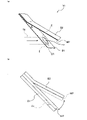
- FIG.1 (a) has shown the perspective state of one surface side
- FIG.1(b) has shown the perspective state of the other surface side.
- FIG.2 (a) showed the perspective view
- FIG.2(b) has shown the side view.
- FIG.3 (a) shows the perspective view
- FIG.3(b) has shown the side view.
- FIG. 1 is a perspective view showing an air conditioning panel according to an embodiment
- Fig. 1(a) shows a perspective view of one side
- Fig. 1(b) shows a perspective view of the other side.
- FIG. 1 shows an example in which the air-conditioning panel is used on a vertical surface, it may be used on an inclined surface or a horizontal surface.
- the air-conditioning panel 1 is formed by bending and welding a plate material so as to have an approximately panel-like appearance. , a condenser 20, an evaporator 30, a latent heat storage material 40, a heat insulating cover 50, various flow paths R1 to R3, and various valves V1 to V3, HV1, and HV2.
- the regenerative absorber 10 is provided on one side of the panel that is exposed to sunlight, and contains an absorbent (such as lithium bromide) that absorbs the vapor refrigerant (such as water vapor) or an adsorbent (such as silica gel) that adsorbs the vapor refrigerant. have at least one.
- the regenerated absorber 10 functions as an absorber that absorbs and adsorbs vapor refrigerant by being provided with an absorbent or an adsorbent.
- the regenerative absorber 10 is heated to, for example, around 100° C. or more by exposing one panel side to sunlight during the day, and releases the absorbed or adsorbed vapor refrigerant. Therefore, the regenerative absorber 10 functions as a regenerator that releases the refrigerant vapor when one surface of the panel is exposed to sunlight.
- the first portion P1 on one side of the panel corresponding to the regenerated absorber 10 is treated to have a solar absorptivity of 80% or more. Due to such treatment, the regenerative absorber 10 is exposed to sunlight during the day and heated to around 100° C. or more. Further, the first portion P1 is processed to have a far-infrared emissivity of 80% or more. Such treatment enables the regenerated absorber 10 to discard the heat of absorption during the night. Examples of the treatment that achieves both a solar absorptance of 80% or more and a far-infrared emissivity of 80% or more include black enamel processing, and in this embodiment, the first portion P1 is subjected to black enamel processing.
- the first vapor refrigerant flow path R1 is a flow path that connects the regenerative absorber 10 and the condenser 20.
- the first vapor refrigerant flow path R1 is provided so as to be exposed to the outside from the panel-shaped body portion 1a, but is not limited to this, and is housed inside the body portion 1a. may be provided.
- the first check valve V1 is provided in the first vapor refrigerant flow path R1 and prevents backflow of liquid refrigerant (e.g., water) or vapor refrigerant (e.g., water vapor) from the condenser 20 to the regenerative absorber 10.
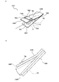
- . 2A and 2B are configuration diagrams showing the details of the first check valve V1 shown in FIG. 1, FIG. 2A showing a perspective view and FIG. 2B showing a side view.
- plate material shall be made thicker than FIG.2(a) for the relationship of illustration, and it shall illustrate.
- the first check valve V1 is provided so as to be able to open and close, for example, the terminal end E (downstream end) of the first vapor refrigerant flow path R1. It comprises members B1, B2 and a motion plate MP.
- the two base materials B1 and B2 are plate materials that are separated by rotation with an angle ⁇ .
- the first base material B1 is formed with an opening O1 having a size corresponding to the diameter of the first vapor refrigerant flow path R1, and the opening O1 is connected to the terminal end E of the first vapor refrigerant flow path R1. state.
- the second base material B2 is a plate material without openings.
- the second base material B2 may have an opening or the like.
- the motion plate MP is a plate member that comes into contact with the first base member B1 in the basic state and closes the opening O1 of the first base member B1.
- the release of vapor refrigerant will increase the pressure in the regenerative absorber 10 creating a pressure differential with the condenser 20 .
- the motion plate MP separates from the first base member B1 due to the pressure difference and rotates (contacts) toward the second base member B2.
- the first check valve V1 is open during the day.
- the regenerated absorber 10 is not heated and the pressure difference does not occur. Therefore, the first check valve V1 is closed.
- the first check valve V1 prevents the liquid refrigerant in the condenser 20 from returning to the regenerative absorber 10 in the evening and at night, and also prevents the liquid refrigerant from vaporizing and returning to be re-absorbed and re-adsorbed by the absorbing liquid or adsorbent. Acts as a deterrent.
- the condenser 20 introduces the vapor refrigerant from the regenerative absorber 10 and liquefies the vapor refrigerant into a liquid refrigerant.
- This condenser 20 is provided on one side of the panel exposed to sunlight.
- the second portion P2 on one side of the panel corresponding to the condenser 20 is treated to have a solar reflectance of 80% or more, more preferably a solar reflectance of 80% or more and far infrared radiation
- the processing is performed so that the ratio is 80% or more (see FIG. 1(a)). Through such treatment, the condenser 20 is maintained in a temperature range of, for example, 40° C. to 50° C.
- White enamel processing is mentioned as the processing for making the solar reflectance of 80% or more and the far-infrared emissivity of 80% or more, and in the present embodiment, the second portion P2 is subjected to the white enamel processing.
- a black enamel and a white enamel are applied to the same surface of the main body 1a. Therefore, on one side, both black and white enamel glazes can be applied and then simultaneously fired, so that both treatments can be performed.
- the liquid refrigerant flow path R2 is a flow path that connects the condenser 20 and the evaporator 30.
- the liquid refrigerant flow path R2 is provided so as to be exposed to the outside from the panel-shaped body portion 1a, but is not limited to this, and is provided inside the body portion 1a. good too.
- the first temperature control valve HV1 is a valve that opens and closes according to the ambient temperature, and is provided for the liquid refrigerant flow path R2.
- 3A and 3B are configuration diagrams showing the details of the first temperature control valve HV1 shown in FIG. 1, FIG. 3A showing a perspective view and FIG. 3B showing a side view.
- plate material shall be thickened rather than FIG.3(a) for the relationship of illustration, and it shall illustrate.
- the first temperature control valve HV1 is provided, for example, so as to be able to open and close the starting end S (upstream end) of the liquid refrigerant flow path R2. It comprises two base members HB1, HB2, a temperature magnet TM, and an action plate HMP.
- the two base materials HB1 and HB2 are plate materials that are separated by rotation with an angle ⁇ .
- the first base material HB1 is formed with an opening O2 having a size corresponding to the diameter of the liquid refrigerant flow path R2, and the opening O2 is connected to the starting end S of the liquid refrigerant flow path R2.
- the second base material HB2 is a plate material without openings. Note that the second base material HB2 may have an opening or the like.
- the temperature magnet TM is provided on the second base material HB2, and is composed of a permanent magnet TM1, a temperature-sensitive ferrite TM2, and a soft iron yoke TM3.
- the temperature-sensitive ferrite TM2 becomes a non-magnetic material above the Curie temperature (specific temperature (for example, 40° C.)) and becomes a magnetic material below the Curie temperature.
- This temperature sensitive ferrite TM2 is interposed between the permanent magnet TM1 and the soft iron yoke TM3. Therefore, the temperature magnet TM exerts a magnetic force on the surroundings when the temperature is below the specific temperature, and does not apply the magnetic force on the surroundings when the temperature is above the specific temperature.
- the operation plate HMP is a plate member made of a magnetic material that comes into contact with the first base member B1 in the basic state and closes the starting end portion S of the liquid refrigerant flow path R2.
- the temperature magnet TM since the temperature inside the condenser 20 is maintained at 40° C. or higher during the daytime, the temperature magnet TM does not exert a magnetic force. Therefore, the motion plate HMP comes into contact with the first base member HB1 to close the liquid refrigerant flow path R2.
- the temperature inside the condenser 20 drops below 40° C. at night, the temperature magnet TM exerts a magnetic force on the surroundings. Therefore, the operation plate HMP made of a magnetic material is separated from the first base material HB1 to open the liquid refrigerant flow path R2.
- the second check valve (first vapor refrigerant check valve) V2 is provided in the liquid refrigerant flow path R2 and prevents the vapor refrigerant from flowing back from the evaporator 30 to the condenser 20 (Fig. 1(b)). )reference).
- the second check valve V2 is similar to the first check valve V1, and is provided so as to be able to open and close the terminal end of the liquid refrigerant flow path R2, and has two base members and an operation plate. , and is configured to open and close by the pressure difference.
- the evaporator 30 is provided on the other side (indoor side) that is not exposed to the sunlight, and evaporates the liquid refrigerant from the condenser 20, thereby taking evaporation heat from the other side of the panel and achieving a cooling effect. It works.
- the inside of the evaporator 30 is, for example, in a vacuum state, so that even if the liquid refrigerant is at room temperature, it can evaporate. Therefore, the liquid refrigerant from the condenser 20 evaporates in the evaporator 30 to cool the other side.
- a second vapor refrigerant flow path (vapor refrigerant flow path) R3 is a flow path that connects the evaporator 30 and the regenerated absorber 10 .
- the second vapor refrigerant flow path R3 is provided so as to be exposed to the outside from the panel-shaped body portion 1a, but is not limited to this, and is housed inside the body portion 1a. may be
- the second temperature control valve HV2 is a valve that opens and closes according to the ambient temperature, and is provided in the second vapor refrigerant flow path R3.
- the second temperature control valve HV2 is similar to the first temperature control valve HV1, and is provided, for example, so as to be able to open and close the starting end of the second vapor refrigerant flow path R3. with a plate.
- the two base materials, the temperature magnet, and the operation plate are the same as those of the first temperature control valve HV1, but the combination of the Curie temperature of the temperature-sensitive ferrite, the permanent magnet, the temperature-sensitive ferrite, and the soft iron yoke is different.
- the Curie temperature of the temperature-sensitive ferrite in the second temperature control valve HV2 is set to about 23° C. (specified temperature), and the second temperature control valve HV2 operates at an ambient temperature of 23° C. or higher in the second vapor refrigerant flow path.
- R3 is opened, and when the ambient temperature is less than 23° C., the second vapor refrigerant flow path R3 is closed.
- the third check valve (second vapor refrigerant check valve) V3 is provided in the second vapor refrigerant flow path R3 and prevents the vapor refrigerant from flowing back from the regenerative absorber 10 to the evaporator 30.
- This third check valve V3 is the same as the first check valve V1, and is provided so as to be able to open and close the terminal end of the second vapor refrigerant flow path R3, and consists of two base members and an operation plate. and is configured to open and close by a pressure difference.
- the flow paths R1 to R3 are tubular, but one or more of the flow paths R1 to R3 may not be tubular, and simply secure a path for the vapor refrigerant or the liquid refrigerant. There may be.
- the latent heat storage material 40 has a phase change temperature (melting point and freezing point) within a specific temperature range (for example, around 23°C).
- a specific temperature range for example, around 23°C.
- the latent heat storage material 40 is provided on the other side of the panel from the evaporator 30 . Therefore, for example, when the air conditioning panel 1 is used as a building material, if the room temperature is above a specific temperature range, the room will be cooled by the latent heat storage material 40, and the evaporator 30 will dissipate the heat of the latent heat storage material 40. It will function as something that takes away and solidifies.
- the heat insulating cover 50 is a light-transmitting film material covering the first portion P1, and corresponds to, for example, an ETFE (Ethylene Tetra Fluoro Ethylene) film.
- ETFE Ethylene Tetra Fluoro Ethylene
- the first portion P1 corresponding to the regenerated absorber 10 is provided with black enamel and has a solar absorptivity of 80% or more.
- the regenerated absorber 10 is heated to, for example, 100° C. or higher, and the absorbing liquid and adsorbent in the regenerated absorber 10 release vapor refrigerant. do.
- the release of vapor refrigerant increases the pressure within the regenerative absorber 10 and creates a pressure differential between the regenerative absorber 10 and the condenser 20 .
- the first check valve V1 provided in the first vapor refrigerant flow path R1 is opened, and the vapor refrigerant passes through the first vapor refrigerant flow path R1 and reaches the condenser 20.
- the condenser 20 even if one side of the panel of the air conditioning panel 1 is exposed to sunlight during the daytime, the second portion P2 is covered with a white enamel so that the solar reflectance is 80% or more and the far-infrared emissivity is 80% or more. 80% or more. Therefore, the inside of the condenser 20 is maintained at about 40.degree. C. to 50.degree. Accordingly, the vapor refrigerant from the regenerated absorber 10 is liquefied in the condenser 20 to become liquid refrigerant.
- the first temperature control valve HV1 since the temperature inside the condenser 20 does not drop below 40°C during the daytime, the first temperature control valve HV1 remains closed. Therefore, the liquid refrigerant accumulates in the condenser 20 without going to the evaporator 30 . In addition, since regeneration is being performed in the regenerated absorber 10 during the daytime, the pressure inside the regenerated absorber 10 is high, the third check valve V3 is closed, and the evaporator 30 does not function. .
- regeneration is performed in the regeneration absorber 10 during the daytime, and liquid refrigerant accumulates in the condenser 20 . If the room temperature is 23° C. or higher during the daytime, the latent heat storage material 40 cools the interior of the room.
- the inside of the evaporator 30 is in a vacuum state. Therefore, the liquid refrigerant in the evaporator 30 evaporates at night.
- the second temperature control valve HV2 is in an open state.
- the third check valve V3 is also opened, and the vapor refrigerant generated in the evaporator 30 reaches the regeneration absorber 10.
- the vapor refrigerant that has reached the regenerative absorber 10 is absorbed and adsorbed by the absorbing liquid or adsorbent in the regenerative absorber 10 .
- black enamel is applied to the first portion P1, and the far-infrared emissivity is set to 80% or more. Therefore, the heat of absorption/adsorption is released favorably.
- the latent heat storage material 40 is cooled by evaporation in the evaporator 30 . Therefore, even if the latent heat storage material 40 is in a molten state during the daytime, it will be in a solidified state again, and the cooling effect to the indoor side will be restored.
- the heat transfer from the latent heat storage material 40 to the liquid refrigerant is much faster than the heat transfer from the indoor air to the latent heat storage material 40 . Therefore, even if the air-conditioning panel 1 is equipped with an amount of latent heat storage material 40 that can cool the room for several days, if the evaporator 30 evaporates for only several hours at night, the latent heat storage material 40 will be substantially all of the material. returns to a solid state.
- the regenerative absorber 10 has an absorption liquid or an adsorbent that absorbs and adsorbs the vapor refrigerant, and releases the vapor refrigerant when exposed to sunlight. Since it is provided, it can be regenerated by being exposed to sunlight, and can be absorbed and adsorbed when it is not exposed to sunlight. It can be used effectively.
- the regenerative absorber 10 and the condenser 20 are formed on one side of the panel that is exposed to sunlight, and the evaporator 30 is formed on the other side of the panel that is opposite to the one side of the panel, evaporation It is possible to prevent the area of the container 30 from being reduced due to the presence of the condenser 20 and the reduction of the air conditioning effect due to the disposal of the heat of condensation.
- the first portion P1 corresponding to the regenerative absorber 10 has a solar absorptivity of 80% or more.
- the second portion P2 corresponding to the condenser 20 is treated to have a solar reflectance of 80% or more. It is possible to achieve a configuration in which regeneration and absorption are performed and a decrease in condensation efficiency in the condenser 20 is suppressed. Therefore, it is possible to solve the problem due to the area competition and to exhibit more sufficient performance.
- black enamel is formed in the first portion P1, a solar absorptivity of 80% or more and a far-infrared emissivity of 80% or more can be achieved by enamel processing.
- the second portion P2 is formed with white enamel, a solar reflectance of 80% or more can be achieved by enamel processing.
- both the first part P1 and the second part P2 can be formed by simultaneous firing, which also contributes to the simplification of the manufacturing process. can.
- the second check valve V2 is provided to prevent backflow of vapor refrigerant from the evaporator 30 toward the condenser 20, the vapor refrigerant generated in the evaporator 30 is prevented from returning to the condenser 20 at night. to properly feed the regenerative absorber 10 with vapor refrigerant. Therefore, it is possible to contribute to performing an appropriate air conditioning operation.
- the third check valve V3 is provided to prevent backflow of the vapor refrigerant from the regenerative absorber 10 to the evaporator 30, the vapor refrigerant generated in the regenerative absorber 10 evaporates during the daytime hours exposed to sunlight.
- the vapor refrigerant can be properly sent to the condenser 20 by preventing it from going to the condenser 30 . Therefore, it is possible to contribute to performing an appropriate air conditioning operation.
- the latent heat storage material 40 is provided in the above embodiment, the latent heat storage material 40 may not be provided if the cooling effect is desired only at night.
- the first and second temperature control valves HV1 and HV2 using the temperature magnet TM are provided, but the present invention is not limited to this, and further includes a temperature sensor and a control section.
- the temperature control valves HV1 and HV2 may be opened and closed by the controller according to the temperature detected by the temperature sensor.
- Air conditioning panel 1a Main body 10: Regenerative absorber 20: Condenser 30: Evaporator 40: Latent heat storage material 50: Heat insulating cover B1: First base material O1: Opening B2: Second base material MP: Operation plate HB1: first base material O2: opening HB2: second base material HMP: action plate HV1: first temperature control valve HV2: second temperature control valve P1: first portion P2: second portion R1: first vapor refrigerant Flow path R2: liquid refrigerant flow path R3: second vapor refrigerant flow path (vapor refrigerant flow path) S: Start end E: End end TM: Temperature magnet TM1: Permanent magnet TM2: Temperature-sensitive ferrite TM3: Soft iron yoke V1: First check valve V2: Second check valve (first vapor refrigerant check valve) V3: Third check valve (second vapor refrigerant check valve)
Landscapes
- Engineering & Computer Science (AREA)
- Mechanical Engineering (AREA)
- General Engineering & Computer Science (AREA)
- Life Sciences & Earth Sciences (AREA)
- Sustainable Development (AREA)
- Chemical & Material Sciences (AREA)
- Combustion & Propulsion (AREA)
- Physics & Mathematics (AREA)
- Thermal Sciences (AREA)
- Sustainable Energy (AREA)
- Sorption Type Refrigeration Machines (AREA)
- Air Filters, Heat-Exchange Apparatuses, And Housings Of Air-Conditioning Units (AREA)
Abstract
Description
1a :本体部
10 :再生吸収器
20 :凝縮器
30 :蒸発器
40 :潜熱蓄熱材
50 :断熱カバー
B1 :第1ベース材
O1 :開口部
B2 :第2ベース材
MP :動作板
HB1 :第1ベース材
O2 :開口部
HB2 :第2ベース材
HMP :動作板
HV1 :第1温度制御弁
HV2 :第2温度制御弁
P1 :第1部位
P2 :第2部位
R1 :第1蒸気冷媒流路
R2 :液冷媒流路
R3 :第2蒸気冷媒流路(蒸気冷媒流路)
S :始端部
E :終端部
TM :温度磁石
TM1 :永久磁石
TM2 :感温性フェライト
TM3 :軟鉄ヨーク
V1 :第1逆止弁
V2 :第2逆止弁(第1蒸気冷媒逆止弁)
V3 :第3逆止弁(第2蒸気冷媒逆止弁)
Claims (5)
- パネル状に形成され空調効果を得る空調パネルであって、
蒸気冷媒を吸収する吸収液又は蒸気冷媒を吸着する吸着剤を有し、太陽光による加熱によって吸収又は吸着した蒸気冷媒を放出する再生吸収器と、
前記再生吸収器において放出された蒸気冷媒を液化して液冷媒とする凝縮器と、
前記凝縮器からの液冷媒を蒸発させる蒸発器と、を備え、
前記再生吸収器と前記凝縮器とは、太陽光に晒される側となるパネル一面側に形成され、
前記蒸発器は、前記パネル一面とは反対面となるパネル他面側に形成され、
前記再生吸収器に対応するパネル一面側の第1部位には、日射吸収率80%以上であって、遠赤外線放射率が80%以上となる処理が施され、
前記凝縮器に対応するパネル一面側の第2部位には、日射反射率80%以上となる処理が施されている
空調パネル。 - 前記第1部位には、黒色ホーローが形成されている
請求項1に記載の空調パネル。 - 前記第2部位には、白色ホーローが形成されている
請求項1又は請求項2に記載の空調パネル。 - 前記凝縮器において液化した液冷媒を前記蒸発器に送り込むための液冷媒流路と、
前記液冷媒流路に設けられ、前記蒸発器から前記凝縮器に向かう蒸気冷媒の逆流を防止する第1蒸気冷媒逆止弁と、
をさらに備える請求項1から請求項3のいずれか1項に記載の空調パネル。 - 前記蒸発器において蒸発した蒸気冷媒を前記再生吸収器に送り込むための蒸気冷媒流路と、
前記蒸気冷媒流路に設けられ、前記再生吸収器から前記蒸発器に向かう蒸気冷媒の逆流を防止する第2蒸気冷媒逆止弁と、
をさらに備える請求項1から請求項4のいずれか1項に記載の空調パネル。
Priority Applications (4)
| Application Number | Priority Date | Filing Date | Title |
|---|---|---|---|
| EP22795432.8A EP4332464A4 (en) | 2021-04-28 | 2022-03-25 | AIR CONDITIONING PANEL |
| AU2022265118A AU2022265118A1 (en) | 2021-04-28 | 2022-03-25 | Air-conditioning panel |
| CN202280024230.4A CN117063028A (zh) | 2021-04-28 | 2022-03-25 | 空调面板 |
| US18/473,201 US12287118B2 (en) | 2021-04-28 | 2023-09-22 | Air-conditioning panel |
Applications Claiming Priority (2)
| Application Number | Priority Date | Filing Date | Title |
|---|---|---|---|
| JP2021076053A JP7620491B2 (ja) | 2021-04-28 | 2021-04-28 | 空調パネル |
| JP2021-076053 | 2021-04-28 |
Related Child Applications (1)
| Application Number | Title | Priority Date | Filing Date |
|---|---|---|---|
| US18/473,201 Continuation US12287118B2 (en) | 2021-04-28 | 2023-09-22 | Air-conditioning panel |
Publications (1)
| Publication Number | Publication Date |
|---|---|
| WO2022230515A1 true WO2022230515A1 (ja) | 2022-11-03 |
Family
ID=83847988
Family Applications (1)
| Application Number | Title | Priority Date | Filing Date |
|---|---|---|---|
| PCT/JP2022/014718 Ceased WO2022230515A1 (ja) | 2021-04-28 | 2022-03-25 | 空調パネル |
Country Status (6)
| Country | Link |
|---|---|
| US (1) | US12287118B2 (ja) |
| EP (1) | EP4332464A4 (ja) |
| JP (1) | JP7620491B2 (ja) |
| CN (1) | CN117063028A (ja) |
| AU (1) | AU2022265118A1 (ja) |
| WO (1) | WO2022230515A1 (ja) |
Cited By (1)
| Publication number | Priority date | Publication date | Assignee | Title |
|---|---|---|---|---|
| JP7667898B1 (ja) | 2024-05-21 | 2025-04-23 | ポルタパーク株式会社 | 空調パネル |
Families Citing this family (1)
| Publication number | Priority date | Publication date | Assignee | Title |
|---|---|---|---|---|
| CN120051409A (zh) | 2022-10-13 | 2025-05-27 | 软银集团股份有限公司 | 控制系统、车辆及控制程序 |
Citations (5)
| Publication number | Priority date | Publication date | Assignee | Title |
|---|---|---|---|---|
| JP2002107003A (ja) * | 2000-07-24 | 2002-04-10 | Mayekawa Mfg Co Ltd | パネル形吸着式冷凍機 |
| JP2019112887A (ja) * | 2017-12-26 | 2019-07-11 | 矢崎エナジーシステム株式会社 | 回転建具 |
| JP6552425B2 (ja) * | 2015-09-18 | 2019-07-31 | ポルタパーク株式会社 | 熱交換装置 |
| JP2021028555A (ja) * | 2019-08-09 | 2021-02-25 | 矢崎エナジーシステム株式会社 | 構造体及びその製造方法 |
| JP2021076053A (ja) | 2019-11-07 | 2021-05-20 | 日野自動車株式会社 | 内燃機関システムの異常診断装置 |
Family Cites Families (7)
| Publication number | Priority date | Publication date | Assignee | Title |
|---|---|---|---|---|
| WO2008114266A2 (en) * | 2007-03-22 | 2008-09-25 | Ewa Tech Ltd | Apparatus and method for solar cooling and air conditioning |
| DE102009043515A1 (de) * | 2009-09-30 | 2011-04-07 | Wolf Beineke | Solarthermisch betriebene Adsorptionskältemaschine zur Raumklimatisierung und Lebensmittelkühlung |
| JP5685485B2 (ja) * | 2011-05-13 | 2015-03-18 | 日立アプライアンス株式会社 | 太陽光熱利用蒸気吸収式冷凍機及び太陽光熱利用システム |
| JP6820199B2 (ja) * | 2014-03-07 | 2021-01-27 | ジニアテック リミテッド | 太陽熱制御システム |
| US9488394B1 (en) * | 2015-08-28 | 2016-11-08 | King Fahd University Of Petroleum And Minerals | System and method for continuously operating a solar-powered air conditioner |
| EP3299759A1 (en) * | 2016-09-21 | 2018-03-28 | Nederlandse Organisatie voor toegepast- natuurwetenschappelijk onderzoek TNO | System and method for thermochemical storage of energy |
| US10663194B2 (en) * | 2017-02-07 | 2020-05-26 | Adam Peter Plesniak | Modular solar air heater |
-
2021
- 2021-04-28 JP JP2021076053A patent/JP7620491B2/ja active Active
-
2022
- 2022-03-25 AU AU2022265118A patent/AU2022265118A1/en not_active Abandoned
- 2022-03-25 EP EP22795432.8A patent/EP4332464A4/en not_active Withdrawn
- 2022-03-25 CN CN202280024230.4A patent/CN117063028A/zh active Pending
- 2022-03-25 WO PCT/JP2022/014718 patent/WO2022230515A1/ja not_active Ceased
-
2023
- 2023-09-22 US US18/473,201 patent/US12287118B2/en active Active
Patent Citations (6)
| Publication number | Priority date | Publication date | Assignee | Title |
|---|---|---|---|---|
| JP2002107003A (ja) * | 2000-07-24 | 2002-04-10 | Mayekawa Mfg Co Ltd | パネル形吸着式冷凍機 |
| JP6552425B2 (ja) * | 2015-09-18 | 2019-07-31 | ポルタパーク株式会社 | 熱交換装置 |
| JP6683861B2 (ja) | 2015-09-18 | 2020-04-22 | ポルタパーク株式会社 | 熱交換装置 |
| JP2019112887A (ja) * | 2017-12-26 | 2019-07-11 | 矢崎エナジーシステム株式会社 | 回転建具 |
| JP2021028555A (ja) * | 2019-08-09 | 2021-02-25 | 矢崎エナジーシステム株式会社 | 構造体及びその製造方法 |
| JP2021076053A (ja) | 2019-11-07 | 2021-05-20 | 日野自動車株式会社 | 内燃機関システムの異常診断装置 |
Non-Patent Citations (1)
| Title |
|---|
| See also references of EP4332464A4 |
Cited By (1)
| Publication number | Priority date | Publication date | Assignee | Title |
|---|---|---|---|---|
| JP7667898B1 (ja) | 2024-05-21 | 2025-04-23 | ポルタパーク株式会社 | 空調パネル |
Also Published As
| Publication number | Publication date |
|---|---|
| EP4332464A4 (en) | 2024-09-25 |
| CN117063028A (zh) | 2023-11-14 |
| US20240011649A1 (en) | 2024-01-11 |
| EP4332464A1 (en) | 2024-03-06 |
| US12287118B2 (en) | 2025-04-29 |
| JP7620491B2 (ja) | 2025-01-23 |
| AU2022265118A1 (en) | 2023-10-05 |
| JP2022170136A (ja) | 2022-11-10 |
Similar Documents
| Publication | Publication Date | Title |
|---|---|---|
| WO2022230515A1 (ja) | 空調パネル | |
| TW201022605A (en) | Low power dehumidifier | |
| JPH0939542A (ja) | 電気自動車用ヒートポンプ冷暖房除湿装置 | |
| US11313172B2 (en) | Rotary fitting | |
| WO2008015981A1 (en) | Air-conditioning apparatus | |
| JP2008249165A (ja) | 室内調湿機 | |
| JP2003312240A (ja) | 車両用空調装置 | |
| JPH11132502A (ja) | 除湿空調システム | |
| JP5443333B2 (ja) | 吸着ヒートポンプ | |
| JP7578088B2 (ja) | 吸着器及び吸着式ヒートポンプ | |
| JP2006232164A (ja) | 車両用空調装置 | |
| JP3925245B2 (ja) | 車両用蓄熱システム | |
| JPH11132501A (ja) | 除湿空調システム | |
| JP4069691B2 (ja) | 車両用空調装置 | |
| JPH08271085A (ja) | 吸着器及び吸着式冷凍装置 | |
| JPH10148415A (ja) | 冷房装置 | |
| JPH09196502A (ja) | ヒートポンプおよびその運転方法 | |
| JPH0658642A (ja) | 吸着式空気調和装置 | |
| JPS5878056A (ja) | 冷暖房用加熱装置 | |
| JP2022080676A (ja) | 太陽光利用吸着式ヒートポンプ | |
| JP2016044910A (ja) | ルーバー装置、給湯システム、空調システム、及び外装材 | |
| JPS63161371A (ja) | ヒ−トポンプ式空気調和機 | |
| JP2004245446A (ja) | 吸着式冷凍機 | |
| JPH086981B2 (ja) | 吸収式熱源装置 | |
| JP2017133794A (ja) | 放熱システム、及び放熱方法 |
Legal Events
| Date | Code | Title | Description |
|---|---|---|---|
| 121 | Ep: the epo has been informed by wipo that ep was designated in this application |
Ref document number: 22795432 Country of ref document: EP Kind code of ref document: A1 |
|
| WWE | Wipo information: entry into national phase |
Ref document number: 2022265118 Country of ref document: AU Ref document number: AU2022265118 Country of ref document: AU |
|
| WWE | Wipo information: entry into national phase |
Ref document number: 202347064119 Country of ref document: IN Ref document number: 202280024230.4 Country of ref document: CN |
|
| ENP | Entry into the national phase |
Ref document number: 2022265118 Country of ref document: AU Date of ref document: 20220325 Kind code of ref document: A |
|
| WWE | Wipo information: entry into national phase |
Ref document number: 2022795432 Country of ref document: EP |
|
| NENP | Non-entry into the national phase |
Ref country code: DE |
|
| ENP | Entry into the national phase |
Ref document number: 2022795432 Country of ref document: EP Effective date: 20231128 |