WO2022230744A1 - 光照射システム - Google Patents
光照射システム Download PDFInfo
- Publication number
- WO2022230744A1 WO2022230744A1 PCT/JP2022/018362 JP2022018362W WO2022230744A1 WO 2022230744 A1 WO2022230744 A1 WO 2022230744A1 JP 2022018362 W JP2022018362 W JP 2022018362W WO 2022230744 A1 WO2022230744 A1 WO 2022230744A1
- Authority
- WO
- WIPO (PCT)
- Prior art keywords
- light
- irradiation
- unit
- target
- illuminance
- Prior art date
- Legal status (The legal status is an assumption and is not a legal conclusion. Google has not performed a legal analysis and makes no representation as to the accuracy of the status listed.)
- Ceased
Links
Images








Classifications
-
- A—HUMAN NECESSITIES
- A61—MEDICAL OR VETERINARY SCIENCE; HYGIENE
- A61N—ELECTROTHERAPY; MAGNETOTHERAPY; RADIATION THERAPY; ULTRASOUND THERAPY
- A61N5/00—Radiation therapy
- A61N5/06—Radiation therapy using light
- A61N5/0613—Apparatus adapted for a specific treatment
- A61N5/0618—Psychological treatment
-
- A—HUMAN NECESSITIES
- A61—MEDICAL OR VETERINARY SCIENCE; HYGIENE
- A61N—ELECTROTHERAPY; MAGNETOTHERAPY; RADIATION THERAPY; ULTRASOUND THERAPY
- A61N5/00—Radiation therapy
- A61N5/06—Radiation therapy using light
- A61N5/0613—Apparatus adapted for a specific treatment
-
- A—HUMAN NECESSITIES
- A61—MEDICAL OR VETERINARY SCIENCE; HYGIENE
- A61N—ELECTROTHERAPY; MAGNETOTHERAPY; RADIATION THERAPY; ULTRASOUND THERAPY
- A61N5/00—Radiation therapy
- A61N5/06—Radiation therapy using light
- A61N5/0601—Apparatus for use inside the body
- A61N5/0603—Apparatus for use inside the body for treatment of body cavities
-
- A—HUMAN NECESSITIES
- A61—MEDICAL OR VETERINARY SCIENCE; HYGIENE
- A61N—ELECTROTHERAPY; MAGNETOTHERAPY; RADIATION THERAPY; ULTRASOUND THERAPY
- A61N5/00—Radiation therapy
- A61N5/06—Radiation therapy using light
- A61N5/0601—Apparatus for use inside the body
- A61N5/0603—Apparatus for use inside the body for treatment of body cavities
- A61N2005/0605—Ear
-
- A—HUMAN NECESSITIES
- A61—MEDICAL OR VETERINARY SCIENCE; HYGIENE
- A61N—ELECTROTHERAPY; MAGNETOTHERAPY; RADIATION THERAPY; ULTRASOUND THERAPY
- A61N5/00—Radiation therapy
- A61N5/06—Radiation therapy using light
- A61N2005/0626—Monitoring, verifying, controlling systems and methods
- A61N2005/0627—Dose monitoring systems and methods
-
- A—HUMAN NECESSITIES
- A61—MEDICAL OR VETERINARY SCIENCE; HYGIENE
- A61N—ELECTROTHERAPY; MAGNETOTHERAPY; RADIATION THERAPY; ULTRASOUND THERAPY
- A61N5/00—Radiation therapy
- A61N5/06—Radiation therapy using light
- A61N2005/0626—Monitoring, verifying, controlling systems and methods
- A61N2005/0627—Dose monitoring systems and methods
- A61N2005/0628—Dose monitoring systems and methods including a radiation sensor
-
- A—HUMAN NECESSITIES
- A61—MEDICAL OR VETERINARY SCIENCE; HYGIENE
- A61N—ELECTROTHERAPY; MAGNETOTHERAPY; RADIATION THERAPY; ULTRASOUND THERAPY
- A61N5/00—Radiation therapy
- A61N5/06—Radiation therapy using light
- A61N2005/0635—Radiation therapy using light characterised by the body area to be irradiated
- A61N2005/0642—Irradiating part of the body at a certain distance
-
- A—HUMAN NECESSITIES
- A61—MEDICAL OR VETERINARY SCIENCE; HYGIENE
- A61N—ELECTROTHERAPY; MAGNETOTHERAPY; RADIATION THERAPY; ULTRASOUND THERAPY
- A61N5/00—Radiation therapy
- A61N5/06—Radiation therapy using light
- A61N2005/0635—Radiation therapy using light characterised by the body area to be irradiated
- A61N2005/0643—Applicators, probes irradiating specific body areas in close proximity
- A61N2005/0645—Applicators worn by the patient
- A61N2005/0647—Applicators worn by the patient the applicator adapted to be worn on the head
- A61N2005/0648—Applicators worn by the patient the applicator adapted to be worn on the head the light being directed to the eyes
-
- A—HUMAN NECESSITIES
- A61—MEDICAL OR VETERINARY SCIENCE; HYGIENE
- A61N—ELECTROTHERAPY; MAGNETOTHERAPY; RADIATION THERAPY; ULTRASOUND THERAPY
- A61N5/00—Radiation therapy
- A61N5/06—Radiation therapy using light
- A61N2005/0658—Radiation therapy using light characterised by the wavelength of light used
- A61N2005/0662—Visible light
-
- A—HUMAN NECESSITIES
- A61—MEDICAL OR VETERINARY SCIENCE; HYGIENE
- A61N—ELECTROTHERAPY; MAGNETOTHERAPY; RADIATION THERAPY; ULTRASOUND THERAPY
- A61N5/00—Radiation therapy
- A61N5/06—Radiation therapy using light
- A61N2005/0658—Radiation therapy using light characterised by the wavelength of light used
- A61N2005/0662—Visible light
- A61N2005/0663—Coloured light
Definitions
- the present disclosure relates to a light irradiation system.
- ganglion cells such as intrinsically photosensitive retinal ganglion cells (iPRGCs) that have photoreceptivity in the eye but have no direct relevance to visual function.
- iPRGCs intrinsically photosensitive retinal ganglion cells
- Non-Patent Document 1 reports that acute and chronic pain is alleviated by irradiation with light in a wavelength band corresponding to green light for eight hours or more.
- a light irradiation system includes an irradiation unit that irradiates irradiation light in a predetermined wavelength band to a predetermined part of a subject's body, and a time measurement that measures the irradiation time for one treatment with the irradiation light. and a control unit that controls the irradiation unit, and the control unit controls the irradiation time to be less than 8 hours.
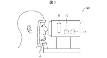
- FIG. 1 is an external view showing a configuration example of a light irradiation system according to Embodiment 1 of the present disclosure
- FIG. It is a block diagram showing an example of the important section composition of the light irradiation system concerning Embodiment 1 of this indication.
- 4 is a flowchart showing the flow of processing performed by the light irradiation system according to Embodiment 1 of the present disclosure
- FIG. 10 is an external view showing a configuration example of a light irradiation system according to Embodiment 2 of the present disclosure
- It is a block diagram which shows an example of the principal part structure of the light irradiation system which concerns on Embodiment 2 of this indication.
- An example of the presentation screen presented by the presentation unit is shown.
- FIG. 11 is a perspective view showing a configuration example of a light irradiation system according to Embodiment 3;
- FIG. 11 is an external view showing a configuration example of a light irradiation system according to Embodiment 4 of the present disclosure;
- FIG. 11 is a block diagram showing an example of a main configuration of a light irradiation system according to Embodiment 4 of the present disclosure; It is a figure which shows an example of the irradiation part by which several light emitting elements are arranged. It is a figure which shows an example of the irradiation part by which several light emitting elements are arranged.
- FIG. 11 is a perspective view showing a configuration example of a light irradiation system according to Embodiment 3;
- FIG. 11 is an external view showing a configuration example of a light irradiation system according to Embodiment 4 of the present disclosure;
- FIG. 11 is a block diagram showing an example of a main configuration of a light
- FIG. 4 is a diagram showing an example of an object displayed on an irradiation unit;
- FIG. FIG. 11 is a flow chart showing the flow of a control method performed by a light irradiation system according to Embodiment 4 of the present disclosure;
- FIG. FIG. 11 is a block diagram showing an example of a main configuration of a light irradiation system according to Embodiment 5 of the present disclosure;
- FIG. 10 is a flow chart showing the flow of a control method performed by a light irradiation system according to Embodiment 5 of the present disclosure;
- FIG. It is a figure which shows the schedule of a light irradiation test. It is a graph which shows the result of an analgesic test. It is a graph which shows the result of the blood enkephalin concentration analysis.
- FIG. 1 is a diagram illustrating a configuration example of a light irradiation system 100 according to one aspect of the present disclosure.
- FIG. 2 is a block diagram showing an example of a main configuration of the light irradiation system 100 according to Embodiment 1 of the present disclosure.
- the light irradiation system 100 includes a light irradiation device 1, which is a device for irradiating a predetermined part of a subject's body with irradiation light in a predetermined wavelength band.
- the light irradiation device 1 may be an installation type device or a wearable device.
- the case where the target to be irradiated with the irradiation light is a human being will be described as an example, but the present invention is not limited to this.
- a variety of animals including dogs, cats, rabbits, guinea pigs, rats, etc., can be subject to irradiation.
- the predetermined part of the subject's body to be irradiated with light may be any part as long as the effect of alleviating pain is obtained, but in the present disclosure, for example, the eyes of the subject are irradiated with light.
- the predetermined portion to be irradiated with light may be, for example, the ear.
- the light irradiation device 1 may be, for example, an earphone type that is used by being inserted into the ear canal of the subject.
- the earphone-type light irradiation device 1 may irradiate light toward the eardrum through the external auditory canal of the object.
- the light irradiation system 100 may irradiate both the eyes and ears of the subject.
- the light irradiation device 1 shown in FIG. 1 may be of an installation type, and may include a fixing portion 4 for fixing the chin and forehead of a target to be irradiated with light. Since the target's face is fixed by the fixing unit 4, the positions of the target's eyes are also fixed. In this case, the subject may be illuminated while sitting on a chair.
- the light irradiation device 1 shown in FIG. 1 can irradiate both eyes of a target with light in a predetermined wavelength band, but is not limited to this.
- the light irradiation device 1 may be configured to irradiate one eye of a subject with light in a predetermined wavelength band.
- the light irradiation device 1 shown in FIG. 1 may be installed, for example, in a medical institution or in the subject's home.
- the light irradiation device 1 includes a control section 10 , an irradiation section 11 and a time measurement section 12 .
- the irradiating unit 11 includes one or more light sources for irradiating a predetermined part of the target's body with irradiation light in a predetermined wavelength band.
- the irradiation unit 11 may include, for example, a light emitting element such as a light emitting diode (LED) and a semiconductor laser (LD) as a light source. By using these light emitting elements, the irradiation section 11 can selectively irradiate monochromatic light with a narrow wavelength width of the emission wavelength.
- the irradiation unit 11 may include a light source that emits white light and an optical filter (for example, a bandpass filter) that transmits only light in a predetermined wavelength band. By selecting and using an appropriate optical filter, the irradiation unit 11 can selectively irradiate irradiation light in a desired wavelength band.
- the predetermined wavelength band of the irradiation light may be a wavelength band of light that is expected to improve the mental and physical condition of the subject by irradiating the eyes of the subject.
- the wavelength band of the illuminating light may be the wavelength band of green light.
- the predetermined wavelength band of the irradiation light is, for example, 450-600 nm, and may be 500-550 nm.
- the illumination light may be green light with a peak top of 525 nm.
- "450 to 600 nm" is intended to include wavelengths of 450 nm and 600 nm, and the same applies to other wavelength designations.
- the wavelength band of the illuminating light may be the wavelength band of violet light.
- the predetermined wavelength band of the irradiation light may be 350-410 nm.
- the wavelength band of the irradiation light may be the wavelength band of blue light.
- an optical filter that blocks ultraviolet rays and near-ultraviolet rays may be further provided in order to reduce damage to the eyes of the subject as much as possible.
- the irradiation light may be continuous light that is continuously irradiated to the eye of the subject, or pulsed light that is intermittently irradiated.
- the time measurement unit 12 measures the irradiation time in one treatment.
- the time measurement unit 12 may start time measurement from the time when the irradiation unit 11 starts light irradiation, and stop time measurement when the light irradiation is stopped.
- Control unit 10 controls the irradiation unit 11 so that the irradiation time for one treatment is less than 8 hours.
- the control unit 10 acquires the irradiation time from the time measuring unit 12 .
- the control unit 10 stops the light irradiation of the irradiation unit 11 when the irradiation time reaches a predetermined treatment time of less than 8 hours.
- the predetermined treatment time may be set in advance, and may be set for each subject, for example.
- the upper limit of the irradiation time in one treatment may be 7.5 hours or less, preferably 4 hours or less, even better 2 hours or less, and most preferably 1 hour or less. According to this, the time during which the subject is restrained by the treatment is reduced, and the physical and mental burden on the subject is reduced.
- the lower limit of the irradiation time in one treatment may be 30 minutes or longer, preferably 1 hour or longer. According to this, a subject can be provided with a pain-relieving effect.
- the light irradiation device 1 that irradiates the ear with irradiation light includes a control unit 10, an irradiation unit 11, and a time measurement unit 12, similar to the above-described light irradiation device 1 that irradiates the eye with light.
- the irradiation unit 11 may be installed on the side of the light irradiation device 1 inserted into the ear canal, and may irradiate light toward the inner part of the ear.
- control unit 10 and the time measurement unit 12 may be installed on the outside of the ear canal, which is the side opposite to the irradiation unit 11 side of the earphone-type light irradiation device 1 . Further, the control unit 10 controls the irradiation unit 11 so that the irradiation time is less than 8 hours.
- FIG. 3 is a flow chart showing the flow of processing executed by the light irradiation system 100 according to this embodiment.
- the irradiation unit 11 irradiates the target's eye with irradiation light in a predetermined wavelength band (irradiation step).
- the time measurement unit 12 starts measuring the irradiation time (time measurement step).
- control unit 10 determines whether or not the irradiation time has reached a predetermined time less than 8 hours. When the control unit 10 determines that the irradiation time has reached the predetermined time, the process proceeds to S4. When the control unit 10 determines that the irradiation time has not reached the predetermined time, the process of S3 is repeated until it is determined that the predetermined time has been reached.
- control unit 10 causes the irradiation unit 11 to stop light irradiation (irradiation time control step).
- the irradiation unit 11 irradiates irradiation light in a predetermined wavelength band
- the time measurement unit 12 measures the irradiation time
- the control unit 10 controls the irradiation time to be less than 8 hours. can be done.
- the subject's eye can be irradiated with light in the predetermined wavelength band for less than 8 hours to provide the subject with a pain-relieving effect.
- the light irradiation system 100 according to Embodiment 1 is a light irradiation system in which the irradiation time for one treatment with irradiation light in a predetermined wavelength band is less than 8 hours.
- the light irradiation performed in one treatment may be divided into multiple times and performed intermittently.
- the procedure of illuminating the subject's eye may be performed more than once.
- the frequency of each treatment is not particularly limited, the treatment may be performed once a day, or the treatment may be performed once every consecutive day.
- once-a-day treatment may be performed for a cycle of 2-5 consecutive days.
- the total treatment time to be performed in one cycle may be set in advance, and if the set total treatment time is set, the treatment time per treatment may vary from day to day. Also, this one cycle may be performed regularly on a weekly or monthly basis. Also, the treatment need not be performed on consecutive days.
- the treatment may be performed every other day, or the treatment may be performed for several hours a day over several consecutive days, followed by a day without treatment, followed by the treatment for several hours a day for several days. .
- multiple treatments per day may be performed. For example, one hour of treatment may be given twice a day. Taking an example in which the total treatment time is 4 hours, for example, a 4-hour treatment may be performed continuously, or a 1-hour treatment may be performed with a rest period of 1 hour after treatment. It may be repeated four times.
- the light irradiation system is a light irradiation system for repeatedly subjecting a predetermined part of a subject's body to light irradiation treatment.
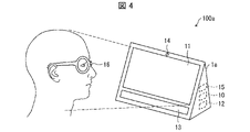
- FIG. 4 is an external view showing a configuration example of a light irradiation system according to Embodiment 2.
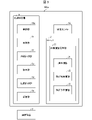
- FIG. FIG. 5 is a block diagram showing a configuration example of a light irradiation system according to the second embodiment.
- the light irradiation system 100a of this embodiment includes, as an example, an installation type light irradiation device 1a.
- the subject receives treatment while facing the light irradiation device 1a.
- the light irradiation device 1a includes an irradiation unit 11, and for example, a presentation unit 13 is provided below the irradiation unit 11.
- the irradiation unit 11 may be arranged on one surface of the light irradiation device 1a.
- the light irradiation device 1 a may include a distance measurement unit 14 that measures the distance between the target and the irradiation unit 11 .
- the light irradiation system 100a is provided with the illumination intensity sensor 16 as an example.
- the light irradiation system 100a of this embodiment may further include a server 2 and an illuminance sensor 16 in addition to the light irradiation device 1a.
- the server 2 may include a target information management section 20 .
- the light irradiation device 1 a also includes a presentation unit 13 , a distance measurement unit 14 , and a communication unit 18 in addition to the control unit 10 a , the irradiation unit 11 , and the time measurement unit 12 .
- the server 2 is communicably connected to the light irradiation device 1 .
- the server 2 may be, for example, a server owned by a medical institution.
- the server 2 has a target information management unit 20 .
- the target information management unit 20 manages target identification information 21, treatment history information 22, and treatment schedule information 23 in association with each target.
- the target identification information 21 is information assigned to each target to identify the target, and is, for example, a string of numbers and a string of characters.
- the treatment history information 22 is information that includes the irradiation time in one treatment that the subject received and the number of treatments that the subject received.
- the treatment history information 22 may include, for example, the date and time when the treatment was received, and may include the time when one treatment was started and the end time.
- the treatment history information 22 may also include an integrated irradiation time obtained by multiplying the number of consecutive days the subject received treatment by the irradiation time of one time.
- the treatment schedule information 23 is information relating to the schedule of treatment scheduled to be received by the subject.
- the treatment schedule information 23 may be, for example, the treatment start time and treatment end time of the next day, or the treatment start date and treatment end date of the next week or month, which is the next treatment cycle.
- the light irradiation device 1a may receive stored information from the target information management unit 20 as necessary.
- the target information management unit 20 associates the target identification information 21, the treatment history information 22, and the treatment schedule information 23 with each target, so that the treatment history information 22 and the treatment schedule can be obtained for each target.
- Information 23 can be managed.
- the presentation unit 13 presents the treatment history information 22 to the target information.
- the presentation unit 13 may be, for example, a display for displaying characters, or a speaker for producing sound.
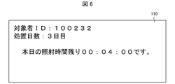
- FIG. 6 shows an example of a presentation screen 110 presented on the presentation unit 13, where the presentation unit 13 is a display.
- the presentation screen 110 may display “subject ID” as the identification information 21 and “treatment days” as the treatment history information 22 .
- the presentation unit 13 may present, together with the treatment history information 22, information regarding the scheduled end time of the treatment currently being received.
- the information about the scheduled end time may be the scheduled end time or the remaining time until the scheduled end time. For example, even if the presentation screen 110 presented by the presentation unit 13 shows the remaining time until the scheduled end time of the treatment currently being received, such as "Today's remaining irradiation time is 00:04:00.” good.
- the distance measurement unit 14 measures the distance between the irradiation unit 11 and the target eye. In order to obtain a pain-relieving effect, it is necessary to irradiate the subject's eye with light of a predetermined illuminance. For that purpose, it is necessary that the irradiation unit 11 and the eye of the object be at an appropriate distance.
- the distance measuring unit 14 is not particularly limited as long as it can measure the distance between the irradiating unit 11 and the eye of the target. For example, it is an infrared camera. According to this, the distance between the irradiation unit 11 and the eye of the object can be measured.
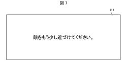
- the presentation unit 13 may present a presentation screen for instructing the subject to move a predetermined part of the body. For example, when illuminating the eyes of a target, the presentation unit 13 instructs the target to change the position of the head or face in order to appropriately adjust the distance between the illuminating unit 11 and the eyes of the target. A presentation screen may be presented. Alternatively, the presentation unit 13 may present a presentation screen instructing the target to change the posture in order to appropriately adjust the distance between the irradiation unit 11 and the eye of the target. Control for causing the presentation unit 13 to present the presentation screen may be performed by the control unit 10 . FIG.
- FIG. 7 shows an example of a presentation screen 111 presented on the presentation unit 13 when the presentation unit 13 is a display.
- the presentation screen 111 presents a message "Please move your face a little closer.”
- the presentation unit 13 presents the presentation screen for instructing the target to move the position of the predetermined part of the body, so that the target can be encouraged to bring the face closer to the irradiation unit 11, for example.
- the distance between the irradiation unit 11 and the target's eye is appropriately adjusted, and the irradiation unit 11 can irradiate the target's eye with light having an appropriate illuminance.
- the communication unit 18 communicates with the external communication device 3 of the light irradiation device 1 .
- the communication device 3 is not particularly limited as long as it has a function of communicating with the light irradiation device 1.
- the communication device 3 may be a PC, a tablet, a smartphone, or the like.
- the communication device 3 may be a PC having a function of directly communicating only with the light irradiation device 1 .
- the communication device 3 may be a communication device 3 owned by the subject.
- the communication unit 18 may transmit the treatment schedule information 23 managed by the target information management unit 20 to the target communication device 3 corresponding to the treatment schedule information.
- the communication unit 18 is an example of treatment schedule information 23 transmitted from the communication unit 18 and displayed on the screen of the target communication device 3 .
- the communication device 3 is, for example, a smart phone owned by the target.
- Information for notifying the target of the treatment schedule is displayed as the treatment schedule information 23 on the screen of the smartphone.
- the screen of the smartphone displays a message that "Today's scheduled irradiation start time is 19:00."
- the communication unit 18 transmits the treatment schedule information 23 to the target communication device, so that the target can know the treatment schedule and receive the treatment without forgetting.
- the illuminance sensor 16 is a sensor that detects illuminance. As described in ⁇ Distance measuring unit 14>, in order to obtain the effect of alleviating pain, it is necessary to irradiate the subject's eye with light of a predetermined illuminance. Therefore, the illuminance sensor 16 may be attached to a location close to the eye of the subject to detect the illuminance of the location close to the eye. In FIG. 4, as an example, the illuminance sensor 16 is attached to the frame of the glasses. The form of the illuminance sensor 16 is not limited to this, and for example, it may be directly attached to the subject's skin, or may be worn by the subject with a cap to which the illuminance sensor 16 is attached.
- the distance measurement unit 14 may measure the distance between the irradiation unit 11 and the target's eye based on the illuminance detected by the illuminance sensor 16 . Thereby, the distance between the irradiation unit 11 and the eye of the object can be measured.
- control unit 10 may adjust the output of the irradiation unit 11 based on the illuminance detected by the illuminance sensor 16 . As a result, the target's eye is illuminated with light having an appropriate illuminance.
- Embodiments 1 and 2 a light irradiation system including an installation type light irradiation device has been described, but in this embodiment, a light irradiation system 100b including a wearable light irradiation device will be described.
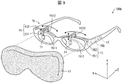
- FIG. 9 is a perspective view showing a configuration example of a light irradiation system 100b according to the third embodiment.
- the light irradiation system 100b includes a light irradiation device 1b.
- the light irradiation device 1b includes a shielding mechanism 17 in addition to the control section 10b, the irradiation section 11, and the time measurement section 12. As shown in FIG. Moreover, the light irradiation device 1 b may include a moving mechanism 15 .
- the shielding mechanism 17 may reduce the illuminance of light different from the irradiation light, or the illuminance of light in a wavelength band different from the predetermined wavelength band included in the light different from the irradiation light.
- the light different from the irradiation light may be, for example, sunlight and light from indoor lighting.
- the shielding mechanism 17 may be made of cloth or resin having light shielding properties, or may be made of metal having light shielding properties or light reflecting properties. Alternatively, the shielding mechanism 17 may include an optical filter that selectively transmits light in a predetermined wavelength band and does not transmit light in a wavelength band different from the predetermined wavelength band. When the shielding mechanism 17 is made of a light shielding material, the shielding mechanism 17 can reduce the illuminance of light from the outside of the light irradiation device 1b over the entire wavelength band.
- the shielding mechanism 17 when the shielding mechanism 17 is made of a material that selectively transmits light in a predetermined wavelength band and does not transmit light in a wavelength band different from the predetermined wavelength band, the shielding mechanism 17 can be used from outside the light irradiation device 1b. It is possible to reduce the illuminance of light in a wavelength band different from the predetermined wavelength band contained in the light of . As a result, the shielding mechanism 17 can reduce the illuminance of light in a wavelength band different from that of the irradiation light reaching the eye of the target when the eye of the target is irradiated with the irradiation light in the predetermined wavelength band. .
- the shielding mechanism 17 is made of a light-reflective material, it is possible to reduce the light from the outside of the light irradiation device 1b, while reflecting the light inside the light irradiation device 1b toward the irradiation target. is.
- the shielding mechanism 17 may be arranged so that there is no gap between the subject wearing the light irradiation device 1b and the light irradiation device 1b. Moreover, the shielding mechanism 17 may be integrated with the light irradiation device 1b or may be a separate body.
- the shielding mechanism 17 may have a goggle-like shape that covers the entire frame portion of the light irradiation device 1b, as shown in FIG. In this case, the shielding mechanism 17 can cover the frame portion of the light irradiation device 1b. This prevents light from the outside of the light irradiation device 1b from entering through the gaps between the forehead, temples, cheeks and nose of the subject and the light irradiation device 1b and reaching the eyes of the subject. be able to.
- the shielding mechanism 17 may be configured to cover the entire head of the subject.
- the subject wearing the light irradiation device 1b shown in FIG. 9 or the subject's head may be covered with a separate shielding mechanism 17.
- FIG. 9 the subject wearing the light irradiation device 1b shown in FIG. 9 or the subject's head may be covered with a separate shielding mechanism 17.
- the shielding mechanism 17 shown in FIG. 9 shields the light reaching both eyes of the target from the outside of the light irradiation device 1b, but is not limited to this.
- the light irradiation device 1b may be configured to include the shielding mechanism 17 for the right eye and the shielding mechanism 17 for the left eye. In this case, only the shielding mechanism 17 on the same side may be used when the illumination light is directed to one eye of the subject. According to this configuration, the shielding mechanism 17 does not block the view of the eye on the side not irradiated with the irradiation light. As a result, the subject can visually recognize the surrounding situation with the eye on the side not irradiated with the irradiation light.
- the light irradiation device 1 b may include a moving mechanism 15 for adjusting the position of the irradiation section 11 .
- the moving mechanism 15 is a mechanism provided for moving the position of the irradiation unit 11 so that the light of the irradiation unit 11 can be irradiated toward the eye of the object, especially the pupil.
- the movement mechanism 15 may have any configuration as long as it is possible to change the position of the irradiation unit 11 with respect to the position of the pupil of the target eye.
- the moving mechanism 15 includes a holding portion 151 that holds the irradiation portion 11 at the first end 1511 and a guide rail 152 for moving the holding portion 151 in the X-axis direction (horizontal direction). may be provided.
- the guide rail 152 may be, for example, a groove provided on the top of the frame of the light irradiation device 1b.
- a second end 1512 opposite to the first end 1511 of the holding portion 151 may slidably contact the inner surface of the groove. Accordingly, the holding portion 151 can move along the guide rail 152 in the X-axis direction.
- the moving mechanism 15 may be capable of moving the position of the irradiation unit 11 in the Y-axis direction (vertical direction).
- the holding part 151 may have a structure that can expand and contract in the Y-axis direction.
- a fixing member (not shown) that fixes the irradiation section 11 to the holding section 151 may be slidable along the holding section 151 and the irradiation section 11 may be movable along the holding section 151 .
- medical personnel such as doctors and nurses in charge of the subject (or the subject himself/herself) can manually change the position of the irradiation unit 11 along the guide rail 152 .
- the light irradiation device 1b can accurately irradiate the eye of the object, particularly the pupil, with the irradiation light and allow the irradiation light to reach the fovea centralis of the retina.
- a light irradiation system includes an irradiation unit that irradiates irradiation light in a predetermined wavelength band to a predetermined part of a subject's body, and a time measurement that measures the irradiation time in one treatment with the irradiation light. and a control unit that controls the irradiation unit, and the control unit controls the irradiation time to be less than 8 hours.
- the predetermined body part of the subject may be at least one of an eye and an ear.
- the duration of the treatment may be 0.5 hours or more.
- the length of time for the treatment may be 4 hours or less.
- the duration of the treatment may be 2 hours or less.
- the length of time for the treatment may be 1 hour or less.
- the duration of the treatment may be 0.5 hours.
- a light irradiation system is, in any one of aspects 1A to 7A, treatment history information including identification information of the target, and the irradiation time and the number of times of the treatment in the treatment received by the target may be further provided with a target information management unit that manages the above in association with each target, and a presentation unit that presents the treatment history information to the target corresponding to the treatment history information.
- the presentation unit may present to each subject the scheduled end time of the treatment that the subject is currently receiving.
- the light irradiation system in aspect 8A or 9A, further includes a communication unit for communicating with the target communication device, and the target information management unit includes identification information of the target and treatment history information including the irradiation time and the number of times in the treatment received by the subject, and treatment schedule information related to the schedule of the treatment scheduled to be received by the subject are managed in association with each other, and the treatment schedule information is managed by It may be transmitted to the target communication device corresponding to the treatment schedule information.
- the light irradiation system according to Aspect 11A of the present invention in any one of Aspects 8A to 10A, further includes a distance measuring unit configured to measure a distance between the irradiating unit and the eye of the target, and the presenting unit comprises: A presentation screen may be presented for instructing the subject to move a position of a predetermined part of the body according to the distance.
- a light irradiation system in Aspect 11A above, includes an illuminance sensor attached to the object, and the distance measurement unit measures the illuminance detected by the illuminance sensor, the irradiating unit and the The distance to the eye of interest may be measured.
- the light irradiation system according to aspect 13A of the present invention is, in aspect 11A or 12A, further comprising an illuminance sensor for applying to the object, and the control unit controls the irradiation of the irradiation unit based on the illuminance detected by the illuminance sensor. Light output may be adjusted.
- a light irradiation system in any one of Aspects 1A to 13A, reduces the illuminance of light in a wavelength band different from the irradiation light and at least in a wavelength band different from the predetermined wavelength band.
- a shielding mechanism may be further provided.
- a light irradiation device includes an irradiation unit that irradiates irradiation light in a predetermined wavelength band to a predetermined part of a subject's body, and a time measurement that measures the irradiation time for one treatment with the irradiation light. and a control unit that controls the irradiation unit, and the control unit controls the irradiation time to be less than 8 hours.
- a light irradiation system control method includes an irradiation step of irradiating a predetermined part of a subject's body with irradiation light in a predetermined wavelength band, and measuring the irradiation time in one treatment with the irradiation light. and an irradiation time control step of controlling the irradiation time to be less than 8 hours.
- FIG. 10 is an external view showing a configuration example of a light irradiation system 100c according to one aspect of the present disclosure.
- FIG. 11 is a block diagram showing an example of a main configuration of a light irradiation system 100c according to Embodiment 4 of the present disclosure.
- the light irradiation system 100c includes a light irradiation device 1c that is a device for irradiating the eyes of a subject with light in a predetermined wavelength band.
- the light irradiation device 1c may be an installation type device.
- a light irradiation device 1c in the light irradiation system 100c shown in FIG. 10 is, as an example, an installation type device.
- the subject may be irradiated with light in a predetermined wavelength band while sitting facing the light irradiation device 1c.
- irradiating an object with light is also referred to as “treatment” or “treatment”.
- the subject may wear glasses having the illuminance information acquisition unit 42 .
- the illuminance information acquisition unit 42 can acquire illuminance information indicating the illuminance in the vicinity of the eye of the object by the light emitted from the light irradiation device 1 .
- the illuminance information acquisition unit 42 may be provided in a device that can be worn by the subject, or may be provided in a chair on which the subject sits. Illuminance in the vicinity of the subject's eye may be obtained.
- the illuminance of the light that illuminates the target's eyes depends, for example, on the position where the target sits, the target's posture, and so on.
- the target information output unit 33 outputs information prompting a change in the state of the target when the illuminance of the light is less than the predetermined illuminance. Details of the target information output unit 33 will be described later.
- the light irradiation system 100c shown in FIG. 10 may be installed in, for example, a medical institution, or may be installed in a subject's home.
- the light irradiation system 100c includes a light irradiation device 1c, an illuminance information acquisition unit 42, and a shielding mechanism 17a.
- the illuminance information acquisition unit 42 is positioned facing the irradiation unit 11a and acquires illuminance information indicating the illuminance of light.
- the illuminance information may be a measured value obtained by measuring illuminance, or may be a determination result of determining whether or not the measured illuminance is within a predetermined range.
- the illuminance information may be an estimate of the illuminance of light reaching the retina of the subject based on the measured illuminance.
- the illuminance information acquisition unit 42 may be, for example, an illuminance sensor. Although the type of the illuminance sensor is not particularly limited, it may use a phototransistor, a photodiode, or a photodiode with an amplifier circuit added.
- the light irradiation device 1c includes an irradiation section 11a and a control section 10c.
- the control unit 10c includes a target information output unit 33, an irradiation control unit 34, and a time measurement unit 12a.
- the irradiation unit 11a irradiates the target's eye with light in a predetermined wavelength band.
- the irradiation unit 11a may include a plurality of light emitting elements that emit light.
- the plurality of light emitting elements may be, for example, light emitting elements such as light emitting diodes (LEDs) and semiconductor lasers (LDs). By using these light-emitting elements, the irradiating section 11a can selectively irradiate monochromatic light having a narrow emission wavelength width.
- the irradiation unit 11a has a plurality of light emitting elements that emit light of a predetermined wavelength, and the plurality of light emitting elements may be arranged.
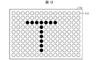
- FIG. 12 is a diagram showing an example of an irradiation section 11a in which a plurality of light emitting elements 112 are arranged.
- 150 light emitting elements are arranged in the irradiation section 11a of FIG. 12, but the number of light emitting elements is not limited to this.
- the plurality of light emitting elements may be the same monochromatic light emitting elements, and for example, only green light emitting elements may be arranged. Alternatively, red, green, and blue light-emitting elements may be arranged. According to this, light in a predetermined wavelength band can be emitted.
- the control for causing the light emitting element to emit light will be described in the description of the irradiation control unit 34 .
- the predetermined illuminance of the light emitted by the irradiation unit 11c may be 4 to 110 Lux. If the illuminance of the light is within the above range, it is possible to provide pain relief to the subject.
- the target information output unit 33 outputs information prompting a change in the state of the target when the illuminance of the light is less than the predetermined illuminance.
- Information prompting a change in the state of the target is information for directing the face of the target toward the irradiation unit 11a, or information for bringing the face of the target closer to the irradiation unit 11a.
- the target information output unit 33 may be a speaker that outputs sounds such as alarms, announcements, and music, or a display that displays characters, numbers, pictures, and the like.
- a warning sound or an alarm may be output when the target information output unit 33 is a speaker and the illuminance of the light is less than a predetermined level.
- the target information output unit 33 outputs voice announcements such as "the light is not properly irradiated”, "please raise your face”, “please straighten your back”, and "please bring your face closer”. may be output.
- voice announcements such as "the light is not properly irradiated”, "please raise your face”, "please straighten your back”, and "please bring your face closer”. may be output.
- the illuminance of the light is less than the predetermined illuminance or exceeds the predetermined illuminance, or if the object sways, there is a possibility that the object is sleeping.
- An announcement or an alarm sound may be output.
- the subject can know that the light is not properly irradiated, and can correct the posture or bring the face closer so that the light is properly irradiated.
- the target information output unit 33 is a speaker
- music is output when the illuminance of the light is above a predetermined level
- music reproduction is interrupted when the illuminance of the light is less than the predetermined level.
- the subject can be conscious of correcting the posture and facing the irradiation unit 11a so as not to interrupt the reproduction of the music.
- the target information output unit 33 is a display and the illuminance of the light is less than a predetermined level, for example, "the light is not properly irradiated", “please raise your head”, “please straighten your back", Characters such as "Please bring your face closer” may be displayed. Also, the target information output unit 33 may display a picture together with the characters.
- the light irradiation device 1 c may include both the above-described speaker and display as the target information output unit 33 .
- the timing at which the target information output unit 33 outputs information may be, for example, when the illumination intensity is below a predetermined level for several tens of seconds.
- the time when the illuminance is less than the predetermined illuminance may be measured, for example, by the time measuring unit 12a, which will be described later.
- the target information output unit 33 may acquire, for example, information that the illuminance of light is less than a predetermined illuminance from the illuminance information acquisition unit 42 described above.
- the target information output unit 33 and the illuminance information acquisition unit 42 may be communicably connected by a wireless communication function or a wired communication function.
- FIGS. 10 and 11 show the configuration in which the light irradiation device 1c includes the target information output unit 33 and outputs information prompting the user to change the target, it is not limited to this.
- a device other than the light irradiation device 1c may output information prompting a change in the state of the object.
- the glasses worn by the target in FIG. 10 may include the target information output unit 33 .
- the target information output unit 33 may output information prompting the change of the target state by sound and vibration. According to this, the target information output unit 33 can output information prompting a change in the state of the target at a location near the target, so that the target can pay attention to the information.
- the information prompting the change of the target state may be configured to be output also from the communication device used by the medical staff.
- the light irradiation device 1c may transmit an output instruction instructing the communication device used by the medical staff to output information prompting a change in the state of the subject. This allows medical personnel to receive information prompting changes in the subject's condition. Further, even if the subject does not notice the output from the subject information output unit 33, the medical staff can directly prompt the subject to change the state of the subject.
- the irradiation control unit 34 may adjust the intensity of the light emitted from the irradiation unit 11a based on the illuminance information. For example, the irradiation control unit 34 may increase the intensity of the light emitted from the irradiation unit 11a based on the illuminance information indicating that the illuminance is less than a predetermined illuminance. Further, when the illumination control unit 34 increases the intensity of the light emitted from the illumination unit 11a but the illumination intensity is less than the predetermined illumination intensity, the information may be output from the target information output unit 33. .
- the irradiation control unit 34 may determine the intensity of the light emitted from the irradiation unit 11a based on the acquired illuminance information. good. Further, the target information output unit 33 may output information to prompt the user to change the angle, height, etc. of the light irradiation device 1c before the irradiation control unit 34 determines the light intensity.
- the intensity of light depends on the number of light-emitting elements that emit light and the magnitude of current applied to the light-emitting elements.
- the irradiation control unit 34 may cause at least one of the plurality of light emitting elements provided in the irradiation unit 11a to emit light.
- the irradiation control unit 34 can irradiate light from the irradiation unit 11a by causing the light emitting element to emit light.
- the irradiation control unit 34 controls the number of the arranged light emitting elements (hereinafter also simply referred to as “elements”) that emit light, thereby adjusting the intensity of the light emitted from the irradiation unit 11a. good.
- the control of the number of light-emitting elements performed by the irradiation control unit 34 will be described with reference to FIG.
- the white light emitting elements 112 are emitting elements
- the black light emitting elements 112 are non-emitting elements.
- the irradiation control unit 34 controls the 137 elements as shown in FIG. may emit light.
- the intensity of the light emitted from the irradiation unit 11a can be adjusted.
- this makes it possible to ensure a predetermined illuminance.
- the irradiation control section 34 may adjust the intensity of the light emitted from the irradiation section 11a by changing the magnitude of the current supplied to the light emitting element.
- the irradiation control unit 34 controls the arrangement of the light emitting elements that emit light among the plurality of arranged light emitting elements, so that an object composed of elements that emit light and elements that do not emit light is displayed. You may display on the irradiation part 11a. Objects are not particularly limited, but may be, for example, letters, numbers, pictures, and the like. In FIG. 12, as an example, the letter "T" is displayed by the light-emitting element 112 that is not emitting light.
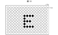
- FIG. 13 is a diagram showing an example of an irradiation section 11a in which a plurality of light emitting elements 112 are arranged.
- 150 light-emitting elements 112 are arranged as in the irradiation section 11a of FIG.
- the illuminating part 11a displays the letter "E" by the light-emitting elements 112 that do not emit light.
- the letter "E” may be displayed as in the irradiation section 11a in FIG.
- the illumination control unit 34 controls the arrangement of the light-emitting elements that emit light among the plurality of arranged light-emitting elements, so that the object can be displayed on the illumination unit 11a.
- the irradiation unit 11a not only emits light but also displays an object, thereby allowing the subject to be treated to maintain concentration.
- the irradiation control unit 34 may control the number of the light emitting elements 112 that emit light.
- the objects displayed are different between the irradiation unit 11a in FIG. 12 and the irradiation unit 11a in FIG.
- the object that the irradiation control unit 34 causes the irradiation unit 11a to display is not particularly limited, and may be a still image, a moving image, a message, or the like.
- a message may include, for example, letters, numbers, and symbols.
- a variety of objects can be applied to keep the subject focused during the treatment and to relax the subject during the treatment.
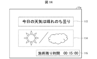
- FIG. 14 is an example of an object displayed on the irradiation unit 11a.
- an object 113 representing the weather in text As an example, an object 114 representing the weather in a picture, and an object 115 representing the remaining treatment time are displayed on the irradiation unit 11a of FIG.
- These letters, pictures, and numbers may be represented by light-emitting elements and non-light-emitting elements among the plurality of light-emitting elements 112, as described above. From the viewpoint of irradiating the subject's eyes with sufficient light, for example, the letters, pictures, and numbers in FIG. may be represented.
- the configuration may be such that the element representing the object is caused to emit light, and the element representing the background is not caused to emit light. Thereby, a predetermined illuminance can be maintained.
- the object that the irradiation control unit 34 causes the irradiation unit 11a to display may be, for example, news text, novel text, or animation. These objects may be changed every unit time. Also, the configuration may be such that the subject selects which object to display before the treatment. According to this, the subject's attention can be drawn, and the subject's face can naturally be directed toward the irradiation unit 11a. It can also relax the target. Also, voices, music, and the like that match these objects may be played from a speaker.
- the irradiation unit 11a in the present disclosure may be, for example, a display capable of displaying characters, pictures, numbers, etc., as described above. You may
- the irradiation control unit 34 controls the ratio of elements that emit light and elements that do not emit light, regardless of what kind of object is displayed on the irradiation unit 11a, so that light with an illuminance equal to or greater than a predetermined illuminance is directed to the eye of the object. may be reached. According to this, it is possible to stably irradiate the target's eye with light in a predetermined wavelength band.
- the irradiation time is the time during which the illuminance of light is equal to or higher than a predetermined illuminance
- the time measurement unit 12a measures the time during which the illuminance of light is equal to or higher than the predetermined illuminance based on the illuminance information.
- the time measuring unit 12a may be, for example, a timer.
- the time measurement unit 12a may start measuring time from the time when the irradiation unit 11a starts irradiating light.
- the time measurement unit 12a may be configured to measure time only when the illuminance of light is equal to or higher than a predetermined illuminance, and not to measure time when the illuminance of light is less than the predetermined illuminance.
- the time measurement unit 12a may be configured to measure the time when the illuminance of light is equal to or higher than a predetermined illuminance and the time when the illuminance of light is less than the predetermined illuminance.
- the time when the illuminance of the light is equal to or higher than a predetermined illuminance may be stored as an integrated time in an object database (not shown) for each object, for example. According to this, the irradiation time can be managed for each object.
- the time measurement unit 12a may terminate the irradiation of the irradiation unit 11a when the length of the irradiation time reaches a predetermined time.
- the predetermined time will be described later in [Predetermined Time of Irradiation].
- the target information output unit 33 may announce the end of the treatment, or the control unit 10c may turn on the lights in the room in order to notify the target of the end of the treatment. According to this, the subject does not have to time himself/herself, and the light is applied for a sufficient time for the pain relief effect to be exerted.
- the predetermined length of time for light irradiation may be 0.5 hours or more and less than 8 hours. Moreover, the upper limit of the predetermined time may be 7.5 hours or less, 4 hours or less, 2 hours or less, or 1 hour or less. According to this, the time during which the subject is restrained by the treatment in which the light is irradiated is reduced, and the physical and mental burden on the subject is reduced.
- the lower limit of the length of the predetermined time may be 30 minutes or more, or may be 1 hour or more. According to this, a subject can be provided with a pain-relieving effect.
- the shielding mechanism 17a may reduce the illuminance of at least light in a wavelength band different from the predetermined wavelength band, which is included in the light different from the light emitted by the light irradiation device 1c.
- the light different from the irradiation light may be, for example, sunlight and light from indoor lighting.
- the shielding mechanism 17a may be made of cloth or resin that has a light-shielding property, or may be made of a metal that has a light-shielding property or light-reflecting property. According to this, the shielding mechanism 17a can reduce the illuminance of the light from the outside of the light irradiation device 1 over the entire wavelength band.
- the shielding mechanism 17a may specifically be a curtain or a darkroom. If the lighting in the room can be turned off, it is not always necessary to provide the shielding mechanism.
- FIG. 15 is a flow chart showing the flow of the control method executed by the light irradiation system 100c according to this embodiment.
- the irradiation unit 11a irradiates the target eye with light in a predetermined wavelength band (irradiation step).
- the illuminance information acquisition unit 42 acquires illuminance information (illuminance information acquisition step).
- the target information output unit 33 outputs information prompting the change of the target state (information output step).
- the irradiation unit 11a irradiates the target eye with light in a predetermined wavelength band
- the illuminance information acquisition unit 42 acquires the illuminance information
- the target information The output unit 33 can output information prompting change of the target state.
- the light irradiation system 100c can stably irradiate the target's eye with the light in the predetermined wavelength band. Therefore, according to the control method described above, for example, it is possible to irradiate the eye of the subject with irradiation light in a predetermined wavelength band that effectively affects the mind and body of the subject.
- the illuminance information acquisition unit 42 acquires illuminance information indicating the illuminance of light, and when the illuminance of light is less than a predetermined illuminance, outputs information prompting a change in the state of the object. It was in the form of Further, the light irradiation device 1c according to the fourth embodiment includes the irradiation section 11a, the target information output section 33, the irradiation control section 34, and the time measurement section 12a.
- the light irradiation device 1d according to the present embodiment may be an installation-type light irradiation device as in the fourth embodiment, and the subject can receive treatment while sitting on a chair, for example.
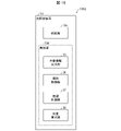
- FIG. 16 is a block diagram showing a configuration example of a light irradiation device 1d according to the fifth embodiment.
- the light irradiation device 1d includes an irradiation unit 11a and a control unit 10d.
- a distance measuring unit 37 and an illuminance calculating unit 38 are further provided.
- the light irradiation device 1d includes the distance measurement unit 37 and the illuminance calculation unit 38, so that the illuminance can be calculated without the illuminance information acquisition unit 42 on the target side. According to this, it is sufficient to use only the light irradiation device 1d for treatment, and there is no need to separately provide the illuminance information acquisition unit 42 on the subject side. For example, there is no need for the subject to wear glasses or the like having the illuminance information acquisition unit 42 .
- the distance measurement unit 37 identifies the position of the eye of the target based on the captured image of the target, and measures the distance from the irradiation unit 11a. That is, the distance measurement unit 37 measures the distance between the target eye and the irradiation unit 11a.
- the captured image of the object may be acquired by, for example, an infrared camera, and the infrared camera may be provided with the light irradiation device 1d or may be arranged separately from the light irradiation device 1d. Also, the captured image may be a moving image in order to identify the position of the eye of the object in real time.
- the method by which the distance measurement unit 37 identifies the position of the target's eye is not particularly limited, and a known method may be applied.
- the distance measurement unit 37 may specify the position of the eye by detecting the pupil based on the difference between the reflected lights of the lighting with different angles.
- the distance measurement unit 37 may calculate the distance from the irradiation unit 11a based on the position of the eye in the image and the size of the eye.
- the distance measuring unit 37 obtains an image of the subject while the subject is seated at a predetermined distance from the irradiation unit 11a, and measures the distance between the eyes of the subject in the obtained image.
- a calibration process may be performed to set the position as a reference position. Thereby, the distance can be accurately measured for each object.
- the illuminance calculator 38 calculates the illuminance of the light at or near the eye of the object based on the distance measured by the distance measurement unit 37 and the intensity of the light emitted from the irradiation unit 11a.
- the illuminance calculation unit 38 holds in advance information indicating the correspondence relationship between the illuminance calculated from the distance and the intensity of the light emitted from the irradiation unit 11a, that is, a relational expression. and the intensity of light may be used to calculate the illuminance of light.
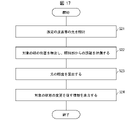
- FIG. 17 is a flow chart showing the flow of the control method executed by the light irradiation device 1d according to this embodiment.
- the irradiation unit 11a irradiates the target eye with light in a predetermined wavelength band (irradiation step).
- the distance measurement unit 37 identifies the eye position of the target based on the captured image of the target, and measures the distance from the irradiation unit 11a (distance measurement step).
- the illuminance calculation unit 38 calculates the illuminance of the irradiation light at or near the eye of the target based on the distance and the intensity of the irradiation light emitted from the irradiation unit 11a (illuminance calculation step).
- the target information output unit 33 outputs information prompting a change in the state of the target when the illuminance of the irradiation light in or near the target eye is less than a predetermined illuminance (target information output step).
- the irradiation unit 11a irradiates the target eye with light in a predetermined wavelength band
- the distance measurement unit 37 measures the distance from the irradiation unit 11a
- the illuminance calculation unit 38 calculates the illuminance of the irradiation light. is calculated
- the target information output unit 33 can output information prompting the change of the target state.
- the light irradiation system 100d can stably irradiate the target's eye with the light in the predetermined wavelength band. Therefore, according to the control method described above, for example, it is possible to irradiate the eye of the subject with irradiation light in a predetermined wavelength band that effectively affects the mind and body of the subject.
- the distance measurement unit 37 identifies the eye position of the target based on the captured image of the target.
- the control unit 10d may identify the target based on the face or eyes of the target in the captured image of the target.
- the target database may store in advance a table in which target face images and target IDs are associated with each other.
- the control unit 10d assigns the corresponding ID in the subject database to the subject about to receive the treatment. may This eliminates the need for the subject or administrator (medical personnel) to enter the subject's ID.
- the target database may store treatment history such as past irradiation time, date, illuminance, and integrated illuminance for each target.
- the control unit 10d may manage treatment for each object based on the treatment history of these object databases. For example, when a subject about to undergo treatment sits down in front of the light irradiation device 1d, the control unit 10d identifies the subject ID corresponding to the subject as described above, and records the treatment history corresponding to the subject ID. Based on this, the irradiation time, illuminance, etc. may be set and the treatment may be started. According to this, appropriate light irradiation can be performed for each object, and a pain relief effect can be given to the object.
- a light irradiation system includes an irradiation unit that irradiates an eye of a subject with light in a predetermined wavelength band, and is positioned opposite the irradiation unit and acquires illuminance information indicating the illuminance of the light.
- An illuminance information acquisition unit, and an object information output unit that outputs information prompting a change in the state of the object when the illuminance of the light is less than a predetermined illuminance.
- the information prompting a change in the state of the target is information for turning the face of the target toward the irradiation unit, or The information may be information for bringing the face closer to the irradiation unit.
- the light irradiation system according to aspect 3B of the present invention may further include an irradiation control unit that adjusts the intensity of the light emitted from the irradiation unit based on the illuminance information in the above aspect 1B or 2B.
- the irradiation unit includes a plurality of light emitting elements that emit the light, the plurality of light emitting elements are arranged, and the irradiation control unit includes , at least one of the plurality of light emitting elements may emit light.
- the illumination control unit controls the number of light emitted from the plurality of arranged light emitting elements, thereby illuminating from the illumination unit.
- the intensity of the light may be adjusted.
- the illumination control unit emits light by controlling the arrangement of the light emitting elements to emit light among the plurality of arranged light emitting elements.
- An object composed of an element that emits light and an element that does not emit light may be displayed on the irradiation unit.
- the light irradiation system according to Aspect 7B of the present invention is, in any one of Aspects 1B to 6B, shielding that reduces illuminance of at least light in a wavelength band different from the predetermined wavelength band, which is included in light different from the light.
- a mechanism may be further provided.
- a light irradiation system according to Aspect 8B of the present invention is a light irradiation system according to any one of Aspects 1B to 7B above, based on the illuminance information. and the irradiation of the irradiation unit may be terminated when the length of the irradiation time reaches a predetermined time.
- the predetermined wavelength band may be 450 to 600 nm.
- the length of the predetermined time may be 0.5 hours or more and less than 8 hours.
- a light irradiation device comprises an irradiation unit that irradiates an eye of a subject with light in a predetermined wavelength band, and a case where the illuminance of the light at or near the eye of the subject is less than a predetermined illuminance. and a target information output unit for outputting information prompting a change in the state of the target.
- a light irradiation device includes an irradiation unit that irradiates an eye of a target with light in a predetermined wavelength band, and based on an image of the target, the position of the eye of the target is specified, a distance measuring unit that measures a distance from the irradiation unit; and an illuminance that calculates the illuminance of the light at or near the eye of the target based on the distance and the intensity of the light irradiated from the irradiation unit. and a target information output unit configured to output information prompting a change in the state of the target when the calculated illuminance is equal to or less than a predetermined illuminance.
- a light irradiation system control method includes an irradiation step of irradiating an eye of a subject with light in a predetermined wavelength band, and illuminance information indicating the illuminance of the light at or near the eye of the subject. and an object information output step of outputting information prompting a change in the state of the object when the intensity of the light at or near the eye is less than a predetermined intensity.
- a method for controlling a light irradiation system includes an irradiation step of irradiating an eye of a subject with light in a predetermined wavelength band from an irradiation unit; and measuring the distance from the irradiating unit, and based on the distance and the intensity of the light irradiated from the irradiating unit, the light at or near the eye of the target and a target information output step of outputting information prompting a change in the state of the target when the illuminance of the light at or near the eye of the target is less than a predetermined illuminance; including.
- control blocks (control units 10, 10a, 10b, 10c and 10d) of the light irradiation systems 100, 100a, 100b, 100c and 100d are realized by logic circuits (hardware) formed in integrated circuits (IC chips) or the like. may be implemented by software.
- the light irradiation systems 100, 100a, 100b, 100c, and 100d are equipped with computers that execute program instructions, which are software that implements each function.
- This computer includes, for example, one or more processors, and a computer-readable recording medium storing the program.
- the processor reads the program from the recording medium and executes it, thereby achieving the object of the present disclosure.
- a CPU Central Processing Unit
- the recording medium a "non-temporary tangible medium" such as a ROM (Read Only Memory), a tape, a disk, a card, a semiconductor memory, a programmable logic circuit, etc. can be used.
- a RAM Random Access Memory
- the program may be supplied to the computer via any transmission medium (communication network, broadcast wave, etc.) capable of transmitting the program.
- One aspect of the present disclosure may also be embodied in the form of a data signal embedded in a carrier wave, with the program embodied by electronic transmission.
- FIG. 18 is a diagram showing a 5-day irradiation schedule of a light irradiation test conducted on rats.
- the schedule in FIG. 18 includes periods in which the lighting in the rat breeding room is ON (light period) and OFF (dark period), the timing of light irradiation to the rat, and the length of the irradiation time. , and a schedule showing the timing of an analgesic effect test and blood sampling.
- the test period was 5 days, with a light period from 9:00 to 21:00 and a dark period from 21:00 to 9:00 the next day.
- an analgesic test and blood sampling were performed on the rats at a certain time during the light period on the first day. Thereafter, at a predetermined time during the dark period, the rats were irradiated with light (wavelength: 527 nm, output intensity: 100 Lux) for a predetermined period of time. Light irradiation was performed continuously for 5 days under the same conditions, and an analgesic test and blood sampling were performed in the same manner as on the 1st day during the photoperiod on the day after the 5th day.
- a pressure stimulus was applied to the paw tip of the rat using a Randall-Selitto type analgesic effect measuring device (manufactured by Unicom Co., Ltd., model number K-201), and the pressure value (mmHg) at which the rat showed a withdrawal response was measured.
- the avoidance response threshold pressure was used.
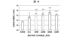
- FIG. 19 is a graph showing the results of an analgesic test.
- the abscissa indicates the continuous irradiation time during repeated light irradiation for 5 days, and the ordinate indicates the avoidance reaction threshold pressure (mmHg) of the rat.
- a higher avoidance threshold pressure indicates that the rat is less sensitive to pain.
- groups with p ⁇ 0.05 are marked with one asterisk (*) and groups with p ⁇ 0.01 are marked with two asterisks. From the graph in FIG. 19, it was found that the rat group exposed to light for 30 minutes had a higher avoidance response threshold pressure than the control group exposed to light for less than 30 minutes.
- the avoidance reaction threshold pressure of the rat group exposed to light for 1 hour was even higher, but the avoidance reaction threshold pressure of the rat groups exposed to light for 2 hours, 4 hours, and 8 hours was lower than that of the rat group exposed to light for 1 hour. It was almost the same as the avoidance response threshold pressure of Rather, the avoidance threshold pressure of the rat group exposed to light for 8 hours was lower than that of the rat group exposed to light for 4 hours. From the above, it was clarified that light irradiation for 30 minutes or longer has a pain-relieving effect on rats. In addition, it was revealed that even if light irradiation was less than 8 hours, the pain alleviation effect on rats was sufficient.
- FIG. 20 is a graph showing the results of blood enkephalin concentration analysis.
- the horizontal axis indicates the continuous irradiation time when the light was repeatedly irradiated for 5 days, and the vertical axis indicates the blood enkephalin concentration (pg/mL) of the rat.
- groups with p ⁇ 0.05 are marked with a single asterisk (*) and groups with p ⁇ 0.01 are marked with two asterisks. From the graph in FIG. 20, it was found that the rat group exposed to light for 30 minutes had a higher blood enkephalin concentration than the control group exposed to light for less than 30 minutes.
- the blood enkephalin concentration of the rat group irradiated with light for 1 hour was higher than that of the rat group irradiated with 30 lights.
- the blood enkephalin concentration tended to decrease in the rat group exposed to light for 2 hours or longer. From the above, it was clarified that light irradiation for 30 minutes or longer has a sufficient pain-relieving effect on rats.
- the light irradiation by the light irradiation system according to the present disclosure has a pain-relieving effect on rats. It is common not only to rats but also to animals in general that an increased blood enkephalin concentration exerts a pain-relieving effect. It is thought that pain relieving effects are similarly observed.
Landscapes
- Health & Medical Sciences (AREA)
- Engineering & Computer Science (AREA)
- Biomedical Technology (AREA)
- Veterinary Medicine (AREA)
- Nuclear Medicine, Radiotherapy & Molecular Imaging (AREA)
- Radiology & Medical Imaging (AREA)
- Life Sciences & Earth Sciences (AREA)
- Animal Behavior & Ethology (AREA)
- General Health & Medical Sciences (AREA)
- Public Health (AREA)
- Pathology (AREA)
- Developmental Disabilities (AREA)
- Child & Adolescent Psychology (AREA)
- Hospice & Palliative Care (AREA)
- Psychiatry (AREA)
- Psychology (AREA)
- Social Psychology (AREA)
- Radiation-Therapy Devices (AREA)
- Eye Examination Apparatus (AREA)
- Medical Treatment And Welfare Office Work (AREA)
Abstract
Description
以下、本開示の一実施形態について詳細に説明する。
本開示の一態様に係る光照射システム100の構成について、図1および図2を用いて説明する。図1は、本開示の一態様に係る光照射システム100の構成例を示す図である。図2は、本開示の実施形態1に係る光照射システム100の要部構成の一例を示すブロック図である。
照射部11は、対象の身体の所定の部位に所定の波長帯の照射光を照射するための1以上の光源を備えている。照射部11は、例えば、発光ダイオード(LED)および半導体レーザ(LD)などの発光素子を光源として備えていてもよい。これらの発光素子を使用することにより、照射部11は、発光波長の波長幅が狭い単色光を選択的に照射することができる。あるいは、照射部11は、白色光を発する光源と、所定の波長帯の光のみを透過させる光学フィルタ(例えば、バンドパスフィルタ)とを備えていてもよい。適切な光学フィルタを選択して用いることにより、照射部11は、所望の波長帯の照射光を選択的に照射することができる。
照射光の所定の波長帯は、対象の眼に照射することで、該対象の心身の状態を改善させる効果が期待される光の波長帯であればよい。
時間計測部12は、1回の処置における照射時間を計測する。時間計測部12は、照射部11が光照射を開始した時間から時間計測を開始し、光照射の停止と共に時間計測を停止してもよい。
制御部10は、1回の処置における照射時間が8時間未満となるように照射部11を制御する。制御部10は、時間計測部12より、照射時間を取得する。制御部10は、該照射時間が、8時間未満の所定の処置の時間に到達した時点で、照射部11の光照射を停止させる。所定の処置の時間は、予め設定されてもよく、例えば、対象毎に設定されてもよい。
1回の処置における照射時間の上限は、7.5時間以下であってよく、4時間以下であればよりよく、2時間以下であればさらによく、1時間以下であれば最もよい。これによれば、対象が処置によって拘束される時間が低減され、対象の身体的負担および精神的負担が小さい。
図3は、本実施形態に係る光照射システム100によって実行される処理の流れを示すフローチャートである。
本開示の他の実施形態について、以下に説明する。説明の便宜上、上記実施形態にて説明した部材と同じ機能を有する部材については、同じ符号を付記し、その説明を繰り返さない。
サーバ2は、一例として、光照射装置1と通信可能に接続される。サーバ2は、例えば医療機関が保有するサーバであってもよい。サーバ2は、対象情報管理部20を備える。
対象情報管理部20は、対象の識別情報21と、処置履歴情報22と、処置予定情報23とを、対象毎に対応付けて管理する。対象の識別情報21は、対象を識別するために対象毎に付与される情報であって、一例として、数字列、文字列からなる。処置履歴情報22は、対象が受けた1回の処置における照射時間と、対象が受けた処置の回数とを含む情報である。処置履歴情報22は、例えば、処置を受けた日時を含んでもよく、1回の処置を開始した時間、および終了時間を含んでもよい。また、処置履歴情報22は、対象が処置を受けた連続した日数と、1回の照射時間とを乗じた、積算の照射時間を含んでもよい。処置予定情報23は、対象が受ける予定の処置のスケジュールに関する情報である。処置予定情報23は、例えば、翌日の処置開始時間、および処置終了時間であってもよく、次の処置サイクルである翌週または翌月の処置開始日、処置終了日などであってもよい。
提示部13は、処置履歴情報22を対象情報に提示する。提示部13は、例えば、文字を表示するためのディスプレイであってもよく、音声を発するスピーカであってもよい。図6は、提示部13がディスプレイであって、提示部13に提示される提示画面110の一例を示す。提示画面110には、識別情報21として「対象者ID」が表示され、処置履歴情報22として「処置日数」が表示されてもよい。また、提示部13は、処置履歴情報22と共に、現在受けている処置の終了予定時刻に関する情報を対象に提示してもよい。終了予定時刻に関する情報は、終了予定時刻であってもよく、終了予定時刻までの残り時間であってもよい。例えば、提示部13に提示される提示画面110には、「本日の照射時間残り00:04:00です」のように、現在受けている処置の終了予定時刻までの残り時間が示されてもよい。
距離計測部14は、照射部11と、対象の眼との距離を計測する。疼痛緩和の効果を得るためには、所定の照度の光が対象の眼に照射されることが要される。そのためには、照射部11と、対象の眼とが適正な距離にあることが必要である。距離計測部14は、照射部11と、対象の眼との距離を計測できれば、特に限定されないが、例えば、赤外線カメラである。これによれば、照射部11と、対象の眼との距離を計測することができる。
通信部18は、光照射装置1の外部の通信機器3と通信する。通信機器3は、光照射装置1と通信する機能を有していれば特に限定されないが、例えば、通信機器3は、PC、タブレット、スマートフォンなどであってよい。また、通信機器3は、光照射装置1とのみ直接通信する機能を有するPCであってもよい。例えば、通信機器3は、対象が所有する通信機器3であってもよい。通信部18は、対象情報管理部20が管理する処置予定情報23を、該処置予定情報に対応する対象の通信機器3に送信してもよい。図8は、対象の通信機器3の画面に表示される、通信部18から送信された処置予定情報23の一例である。通信機器3は、一例として、対象が所有するスマートフォンである。該スマートフォンの画面には、処置予定情報23として、対象に処置の予定を通知するための情報が表示される。一例として、スマートフォンの画面には、「本日の照射開始予定時間は19時です。」というメッセージが表示されている。通信部18が、対象の通信機器に処置予定情報23を送信することにより、対象は処置予定を知ることができ、忘れずに処置を受けることができる。
照度センサ16は、照度を検出するセンサである。<距離計測部14>でも述べたように、疼痛緩和の効果を得るためには、所定の照度の光が対象の眼に照射されることが要される。そのため、照度センサ16は、対象の眼に近い場所に付され、眼に近い場所の照度を検出してよい。図4では、一例として、メガネのフレームに照度センサ16が付されている。照度センサ16の形態はこれに限定されず、例えば、対象の皮膚に直接貼付される形態でもよく、照度センサ16が付された帽子を対象が被る形態であってもよい。
本開示の他の実施形態について、以下に説明する。説明の便宜上、上記実施形態にて説明した部材と同じ機能を有する部材については、同じ符号を付記し、その説明を繰り返さない。
遮蔽機構17は、照射光とは異なる光の照度、または照射光とは異なる光に含まれる、所定の波長帯とは異なる波長帯の光の照度を減じてもよい。ここで、照射光とは異なる光とは、例えば、太陽光、および屋内の照明からの光であってもよい。
また、光照射装置1bは、照射部11の位置を調節するために、移動機構15を備えていてもよい。移動機構15は、対象の眼、特に瞳孔に向けて照射部11の光を照射できるよう、照射部11の位置を移動させるために設けられた機構である。
本発明の態様1Aに係る光照射システムは、対象の身体の所定の部位に所定の波長帯の照射光を照射する照射部と、前記照射光が1回の処置における照射時間を計測する時間計測部と、前記照射部を制御する制御部と、を備え、前記制御部は、前記照射時間が8時間未満となるように制御する。
(光照射システム100cの構成)
本開示の一態様に係る光照射システム100cの構成について、図10および図11を用いて説明する。図10は、本開示の一態様に係る光照射システム100cの構成例を示す外観図である。図11は、本開示の実施形態4に係る光照射システム100cの要部構成の一例を示すブロック図である。
照度情報取得部42は、照射部11aに対向して位置し、光の照度を示す照度情報を取得する。ここで、照度情報は、照度を測定した測定値であってもよいし、測定された照度が所定の範囲内であるか否かを判定した判定結果であってもよい。あるいは、照度情報は、測定された照度に基づいて、対象の網膜に到達する光の照度を推定した推定値であってもよい。照度情報取得部42は、例えば、照度センサであってよい。照度センサの種類は特に限定されないが、フォトトランジスタを用いたものであってもよく、フォトダイオードを用いたものであってもよく、フォトダイオードにアンプ回路を追加したものであってもよい。
光照射装置1cは、照射部11a、および制御部10cを備える。制御部10cは、対象情報出力部33、照射制御部34、および時間計測部12aを備える。
照射部11aは、対象の眼に所定の波長帯の光を照射する。照射部11aは、光を発する複数の発光素子を備えていてもよい。複数の発光素子は、例えば、発光ダイオード(LED)および半導体レーザ(LD)などの発光素子であってもよい。これらの発光素子を使用することにより、照射部11aは、発光波長の波長幅が狭い単色光を選択的に照射することができる。
照射部11aは、所定の波長の光を発する複数の発光素子を有しており、これら複数の発光素子は配列されていてもよい。図12は、複数の発光素子112が配列されている照射部11aの一例を示す図である。図12の照射部11aには、一例として発光素子が150個配列されているが、発光素子の数はこれに限定されない。複数の発光素子は、同じ単色の発光素子であってよく、例えば、緑色の発光素子のみが配列されていてもよい。また、赤色、緑色、青色の発光素子が配列されていてもよい。これによれば、所定の波長帯の光を発することができる。発光素子を発光させる制御については、照射制御部34の説明において行う。
照射部11cによって、照射される光の所定の照度は、4~110Luxであってよい。光の照度が上記の範囲であれば、対象に疼痛緩和の効果を与えることができる。
対象情報出力部33は、光の照度が所定の照度未満である場合、対象の状態の変更を促す情報を出力する。対象の状態の変更を促す情報は、該対象の顔の向きを照射部11aの方へ向けさせる情報、または、対象の顔を照射部11aに近づけさせる情報である。対象情報出力部33は、アラーム、アナウンス、音楽などの音を出力するスピーカであってもよく、文字、数字および絵などを表示するディスプレイであってもよい。
照射制御部34は、照度情報に基づいて、照射部11aから照射する光の強度を調整してもよい。例えば、照射制御部34は、照度が所定の照度未満であるという照度情報に基づいて、照射部11aから照射する光の強度を強くしてもよい。また、照射制御部34が照射部11aから照射する光の強度を強くしたにも拘わらず、照度が所定の照度未満である場合は、対象情報出力部33から情報を出力する構成であってよい。
照射制御部34が、照射部11aに表示させるオブジェクトは、特に限定されないが、静止画、動画、メッセージなどであってもよい。メッセージには、例えば、文字、数字、記号が含まれてもよい。オブジェクトは、処置の間の対象の集中力を保持するため、また、対象を処置中にリラックスさせるために、様々なものが適用可能である。
本実施形態において、照射時間は、光の照度が所定の照度以上である時間であり、時間計測部12aは、照度情報に基づいて、前記光の照度が所定の照度以上である時間を照射時間として計測する。時間計測部12aは、例えばタイマーであってよい。例えば、時間計測部12aは、照射部11aが光の照射を開始した時間から時間計測を開始すればよい。時間計測部12aは、光の照度が所定の照度以上であるときのみ時間を計測し、光の照度が所定の照度未満であるときは時間を計測しない構成であってよい。または、時間計測部12aは、光の照度が所定の照度以上であるときの時間と、光の照度が所定の照度未満であるときの時間をそれぞれ計測する構成であってもよい。また、光の照度が所定の照度以上であるときの時間を積算時間として、例えば対象毎に対象データベース(不図示)に格納してもよい。これによれば、対象毎に照射時間を管理することができる。
光が照射される所定時間の長さは0.5時間以上8時間未満であってもよい。また、所定時間の上限は、7.5時間以下であってもよく、4時間以下であってもよく、2時間以下であってもよく、1時間以下であってもよい。これによれば、対象が光を照射される処置によって拘束される時間が低減され、対象の身体的負担および精神的負担が小さい。
遮蔽機構17aは、光照射装置1cが照射する光とは異なる光に含まれる、少なくとも所定の波長帯とは異なる波長帯の光の照度を減じてもよい。ここで、照射光とは異なる光とは、例えば、太陽光、および屋内の照明からの光であってもよい。
図15は、本実施形態に係る光照射システム100cによって実行される制御方法の流れを示すフローチャートである。
本開示の他の実施形態について、以下に説明する。説明の便宜上、上記実施形態にて説明した部材と同じ機能を有する部材については、同じ符号を付記し、その説明を繰り返さない。
実施形態4に係る光照射システム100cは、照度情報取得部42が光の照度を示す照度情報を取得し、光の照度が所定の照度未満である場合、対象の状態の変更を促す情報を出力する形態であった。また、実施形態4に係る光照射装置1cは、照射部11a、対象情報出力部33、照射制御部34、時間計測部12aを備えていた。
距離計測部37は、対象が撮像された画像に基づいて、該対象の眼の位置を特定し、照射部11aからの距離を計測する。すなわち、距離計測部37は、対象の眼と、照射部11aとの距離を計測する。対象が撮像された画像は、例えば、赤外線カメラによって取得されればよく、赤外線カメラは光照射装置1dが備えていてもよく、光照射装置1dとは別に配されていてもよい。また、撮像される画像は、対象の眼の位置をリアルタイムで特定するために、動画像であってもよい。
照度算出部38は、距離計測部37が計測した距離と、照射部11aから照射された光の強度とに基づいて、対象の眼または眼の近傍における光の照度を算出する。照度算出部38は、予め、距離と、照射部11aから照射された光の強度とから算出される照度の対応関係を示す情報、すなわち関係式を保持しており、該情報に基づいて、距離と、光の強度とから光の照度を算出してもよい。
図17は、本実施形態に係る光照射装置1dによって実行される制御方法の流れを示すフローチャートである。
実施形態5では、距離計測部37が、対象が撮像された画像に基づいて、該対象の眼の位置を特定した。制御部10dは、例えば、対象が撮像された画像において、対象の顔、または眼に基づいて、対象を特定してもよい。例えば、予め対象データベースに、対象の顔画像と、対象IDとを対応付けた表が格納されていてもよい。制御部10dは、処置をこれから受けようとする対象の顔の画像と、対象データベース内の画像とが一致する場合、処置を受けようとする対象に対して対象データベース内の対応したIDを付してもよい。これによれば、対象または管理者(医療関係者)が対象のIDを入力する必要がない。
本発明の態様1Bに係る光照射システムは、対象の眼に所定の波長帯の光を照射する照射部と、前記照射部に対向して位置し、前記光の照度を示す照度情報を取得する照度情報取得部と、前記光の照度が所定の照度未満である場合、該対象の状態の変更を促す情報を出力する対象情報出力部と、を備える。
光照射システム100、100a、100b、100cおよび100dの制御ブロック(制御部10、10a、10b、10cおよび10d)は、集積回路(ICチップ)等に形成された論理回路(ハードウェア)によって実現してもよいし、ソフトウェアによって実現してもよい。
ラット(n=5)に対して光照射試験を行い、照射時間について検討した。図18は、ラットに対して行った光照射試験の5日間の照射スケジュールを示す図である。図18のスケジュールは、具体的に、ラットの飼育室の照明がON(明期)および照明がOFF(暗期)の期間、ラットに対して光照射を行う照射のタイミング、照射時間の長さ、および鎮痛効果試験と採血とを行うタイミングを示すスケジュールである。試験期間は5日間であり、9時から21時までは明期、21時から翌日の9時までは暗期とした。
ランダルセリット式鎮痛効果測定装置(ユニコム株式会社製、型番K-201)を用いて、ラットの足先端に圧刺激を加え、ラットが逃避反応を示す加圧値(mmHg)を測定し、
回避反応閾値圧とした。
ラットから採血した血液の血中エンケファリン濃度(pg/mL)を分析した。分析はRat Enkephalin ELISA Kit(LSBio)を用いて行った。
得られた鎮痛試験結果、血中エンケファリン濃度分析結果は平均値±標準誤差で示した。検定はStudentのt検定を行い、有意水準をp<0.05およびp<0.01に設定した。
10、10a、10b、10c、10d 制御部
11、11a 照射部
12、12a 時間計測部
13 提示部
14 距離計測部
16 照度センサ
18 通信部
20 対象情報管理部
21 識別情報
22 処置履歴情報
23 処置予定情報
42 照度情報取得部
33 対象情報出力部
34 照射制御部
17、17a 遮蔽機構
37 距離計測部
38 照度算出部
100、100a、100b、100c、100d 光照射システム
Claims (19)
- 対象の身体の所定の部位に所定の波長帯の光を照射する照射部と、
前記光の1回の処置における照射時間を計測する時間計測部と、
前記照射部を制御する制御部と、を備え、
前記制御部は、前記照射時間が8時間未満となるように制御する、
光照射システム。 - 前記対象の身体の所定の部位とは、眼および耳の少なくとも1つである、
請求項1に記載の光照射システム。 - 前記処置の時間の長さが0.5時間以上である、
請求項1または2に記載の光照射システム。 - 前記処置の時間の長さが1時間以下である、
請求項1または2に記載の光照射システム。 - 前記対象の識別情報と、該対象が受けた前記処置における前記照射時間および前記処置の回数を含む処置履歴情報とを、対象毎に対応付けて管理する対象情報管理部と、
前記処置履歴情報を、該処置履歴情報に対応する前記対象に提示する提示部と、をさらに備える、
請求項1または2に記載の光照射システム。 - 前記提示部は、前記対象が現在受けている前記処置の終了予定時刻に関する情報を各対象に提示する、
請求項5に記載の光照射システム。 - 前記対象の通信機器と通信するための通信部をさらに備え、
前記対象情報管理部は、前記対象の識別情報と、該対象が受けた前記処置における前記照射時間および前記回数を含む処置履歴情報と、該対象が受ける予定の前記処置のスケジュールに関する処置予定情報とを対応付けて管理しており、
前記処置予定情報を、該処置予定情報に対応する前記対象の通信機器に送信する、
請求項5に記載の光照射システム。 - 前記照射部と、前記対象の眼と、の距離を計測する距離計測部をさらに備え、
前記提示部は、前記距離に応じて、前記対象に前記身体の所定の部位の位置を動かすよう指示するための提示画面を提示する、
請求項5に記載の光照射システム。 - 前記対象に付すための照度センサをさらに備え、
前記距離計測部は、前記照度センサの検出照度に基づいて、前記照射部と、前記対象の眼との距離を計測する
請求項8に記載の光照射システム。 - 前記対象に付すための照度センサをさらに備え、
前記制御部は、前記照度センサの検出照度に基づいて、前記照射部の光の出力を調整する、
請求項8に記載の光照射システム。 - 前記所定の波長帯の光とは異なる光に含まれる、少なくとも前記所定の波長帯とは異なる波長帯の光の照度を減じる遮蔽機構をさらに備える、
請求項1または2に記載の光照射システム。 - 前記照射部に対向して位置し、前記光の照度を示す照度情報を取得する照度情報取得部と、
前記光の照度が所定の照度未満である場合、該対象の状態の変更を促す情報を出力する対象情報出力部と、をさらに備える、
請求項2に記載の光照射システム。 - 前記対象の状態の変更を促す情報は、該対象の顔の向きを前記照射部の方へ向けさせる情報、または、該対象の顔を前記照射部に近づけさせる情報である、
請求項12に記載の光照射システム。 - 前記照度情報に基づいて、前記照射部から照射する前記光の強度を調整する照射制御部をさらに備える、
請求項12に記載の光照射システム。 - 前記照射部は、前記光を発する複数の発光素子を有し、
前記複数の発光素子は、配列されており、
照射制御部は、前記複数の発光素子の少なくとも1つを発光させる、請求項14に記載の光照射システム。 - 前記照射制御部は、配列されている前記複数の発光素子のうち、発光させる数を制御することによって、前記照射部から照射する前記光の強度を調整する、請求項15に記載の光照射システム。
- 前記照射制御部は、配列されている前記複数の発光素子のうち、発光させる発光素子の配置を制御することによって、発光している素子と、発光していない素子とから構成されるオブジェクトを前記照射部に表示する、請求項16に記載の光照射システム。
- 前記照射時間は、前記光の照度が所定の照度以上である時間であり、
前記時間計測部は、前記照射時間の長さが、所定時間に達した場合に前記照射部の照射を終了させる、
請求項12に記載の光照射システム。 - 前記所定の波長帯は、450~600nmである、
請求項1に記載の光照射システム。
Priority Applications (5)
| Application Number | Priority Date | Filing Date | Title |
|---|---|---|---|
| EP22795657.0A EP4331663A4 (en) | 2021-04-27 | 2022-04-21 | LIGHT IRRADIATION SYSTEM |
| US18/557,844 US20240226598A1 (en) | 2021-04-27 | 2022-04-21 | Light irradiation system |
| CN202280027926.2A CN117202967A (zh) | 2021-04-27 | 2022-04-21 | 光照射系统 |
| JP2023517473A JP7631510B2 (ja) | 2021-04-27 | 2022-04-21 | 光照射システム |
| JP2025017784A JP2025073124A (ja) | 2021-04-27 | 2025-02-05 | 光照射システム、光照射装置、制御方法、および制御プログラム |
Applications Claiming Priority (4)
| Application Number | Priority Date | Filing Date | Title |
|---|---|---|---|
| JP2021-075308 | 2021-04-27 | ||
| JP2021075308 | 2021-04-27 | ||
| JP2021106968 | 2021-06-28 | ||
| JP2021-106968 | 2021-06-28 |
Publications (1)
| Publication Number | Publication Date |
|---|---|
| WO2022230744A1 true WO2022230744A1 (ja) | 2022-11-03 |
Family
ID=83847068
Family Applications (1)
| Application Number | Title | Priority Date | Filing Date |
|---|---|---|---|
| PCT/JP2022/018362 Ceased WO2022230744A1 (ja) | 2021-04-27 | 2022-04-21 | 光照射システム |
Country Status (4)
| Country | Link |
|---|---|
| US (1) | US20240226598A1 (ja) |
| EP (1) | EP4331663A4 (ja) |
| JP (2) | JP7631510B2 (ja) |
| WO (1) | WO2022230744A1 (ja) |
Cited By (1)
| Publication number | Priority date | Publication date | Assignee | Title |
|---|---|---|---|---|
| WO2025192632A1 (ja) * | 2024-03-15 | 2025-09-18 | 京セラ株式会社 | 制御装置、制御方法、および制御システム |
Families Citing this family (1)
| Publication number | Priority date | Publication date | Assignee | Title |
|---|---|---|---|---|
| CN115845269B (zh) * | 2022-12-19 | 2024-04-02 | 光朗(海南)生物科技有限责任公司 | 一种用于眼睛的光照理疗装置 |
Citations (2)
| Publication number | Priority date | Publication date | Assignee | Title |
|---|---|---|---|---|
| JP2004313213A (ja) * | 2003-04-10 | 2004-11-11 | Toshio Oshiro | 光治療器具 |
| WO2018124036A1 (ja) * | 2016-12-26 | 2018-07-05 | 株式会社坪田ラボ | 表示システム、電子機器及び照明システム |
Family Cites Families (9)
| Publication number | Priority date | Publication date | Assignee | Title |
|---|---|---|---|---|
| KR100900248B1 (ko) | 2008-03-17 | 2009-06-01 | 주식회사 큐레이 | 헬스 케어 역할을 갖는 백라이트 유닛 |
| KR101458415B1 (ko) * | 2008-03-19 | 2014-11-07 | 주식회사 큐레이 | 헬스케어를 위한 광소자가 장착된 착용물 |
| BRPI0914514A2 (pt) | 2008-10-31 | 2016-01-05 | Qray Inc | aparelho de irradiação de luz equipado com uma fonte de luz de led para reforçar a função imune mediada por células. |
| GB201301958D0 (en) * | 2013-02-04 | 2013-03-20 | Polyphotonix Ltd | Medical apparatus,system and method |
| SG11201804718UA (en) * | 2015-12-02 | 2018-07-30 | Tsubota Lab Inc | Irradiation device |
| KR20250153860A (ko) * | 2016-11-17 | 2025-10-27 | 코그니토 쎄라퓨틱스, 인코포레이티드 | 시각 자극을 통한 신경 자극 방법 및 시스템 |
| EP3568194A2 (en) * | 2017-01-13 | 2019-11-20 | Luma Therapeutics, Inc. | Uvb light therapy for immune disorders |
| US20180345034A1 (en) * | 2017-06-06 | 2018-12-06 | Peter Butzloff | Myopia inhibition apparatus and ocular method |
| MX2021006509A (es) * | 2018-12-06 | 2021-07-06 | Alcon Inc | Sistemas y metodos para el tratamiento de afecciones oculares. |
-
2022
- 2022-04-21 JP JP2023517473A patent/JP7631510B2/ja active Active
- 2022-04-21 EP EP22795657.0A patent/EP4331663A4/en active Pending
- 2022-04-21 US US18/557,844 patent/US20240226598A1/en active Pending
- 2022-04-21 WO PCT/JP2022/018362 patent/WO2022230744A1/ja not_active Ceased
-
2025
- 2025-02-05 JP JP2025017784A patent/JP2025073124A/ja active Pending
Patent Citations (2)
| Publication number | Priority date | Publication date | Assignee | Title |
|---|---|---|---|---|
| JP2004313213A (ja) * | 2003-04-10 | 2004-11-11 | Toshio Oshiro | 光治療器具 |
| WO2018124036A1 (ja) * | 2016-12-26 | 2018-07-05 | 株式会社坪田ラボ | 表示システム、電子機器及び照明システム |
Non-Patent Citations (2)
| Title |
|---|
| MOHAB M. IBRAHIMA: "Long-lasting antinociceptive effects of green light in acute and chronic pain in rats", PAIN., vol. 158, no. 2, 2017, pages 347 - 360 |
| See also references of EP4331663A4 |
Cited By (1)
| Publication number | Priority date | Publication date | Assignee | Title |
|---|---|---|---|---|
| WO2025192632A1 (ja) * | 2024-03-15 | 2025-09-18 | 京セラ株式会社 | 制御装置、制御方法、および制御システム |
Also Published As
| Publication number | Publication date |
|---|---|
| EP4331663A4 (en) | 2025-07-09 |
| JPWO2022230744A1 (ja) | 2022-11-03 |
| US20240226598A1 (en) | 2024-07-11 |
| JP2025073124A (ja) | 2025-05-12 |
| EP4331663A1 (en) | 2024-03-06 |
| JP7631510B2 (ja) | 2025-02-18 |
Similar Documents
| Publication | Publication Date | Title |
|---|---|---|
| JP6559666B2 (ja) | 光線療法を提供し、概日リズムを修正するためのシステム及び方法 | |
| EP2670481B1 (en) | Spectacles for light therapy | |
| JP6279645B2 (ja) | 眼鏡フレーム及びコンタクトレンズを備える光線療法システム | |
| RU2545904C2 (ru) | Система и способ для проведения фототерапии | |
| US20200289321A1 (en) | Circadian Rhythm Adjustment System | |
| JP2025073124A (ja) | 光照射システム、光照射装置、制御方法、および制御プログラム | |
| JP2016525408A (ja) | 光療法を提供し、概日リズムを修正するシステム及び方法 | |
| EP3884737B1 (en) | Head worn electronic device | |
| US20150375008A1 (en) | Portable illuminating device for manipulating the circadian clock of a subject | |
| WO2019153968A1 (zh) | 配置调节生物节律光照装置发光参数的方法及装置 | |
| US20060181677A1 (en) | Method or apparatus for inhibiting myopia development in humans | |
| CN117202967A (zh) | 光照射系统 | |
| US20230293905A1 (en) | Light irradiation system, wearable device, installation-type light irradiation device, and light irradiation method | |
| HK1191885B (en) | Spectacles for light therapy | |
| HK1191886B (en) | Light therapy system including spectacle frames and contact lenses | |
| AU2012212144A1 (en) | Light therapy system including spectacle frames and contact lenses |
Legal Events
| Date | Code | Title | Description |
|---|---|---|---|
| 121 | Ep: the epo has been informed by wipo that ep was designated in this application |
Ref document number: 22795657 Country of ref document: EP Kind code of ref document: A1 |
|
| WWE | Wipo information: entry into national phase |
Ref document number: 202280027926.2 Country of ref document: CN |
|
| WWE | Wipo information: entry into national phase |
Ref document number: 2023517473 Country of ref document: JP |
|
| WWE | Wipo information: entry into national phase |
Ref document number: 18557844 Country of ref document: US |
|
| WWE | Wipo information: entry into national phase |
Ref document number: 2022795657 Country of ref document: EP |
|
| NENP | Non-entry into the national phase |
Ref country code: DE |
|
| ENP | Entry into the national phase |
Ref document number: 2022795657 Country of ref document: EP Effective date: 20231127 |