WO2022230904A1 - アーク溶接継手およびアーク溶接方法 - Google Patents
アーク溶接継手およびアーク溶接方法 Download PDFInfo
- Publication number
- WO2022230904A1 WO2022230904A1 PCT/JP2022/018950 JP2022018950W WO2022230904A1 WO 2022230904 A1 WO2022230904 A1 WO 2022230904A1 JP 2022018950 W JP2022018950 W JP 2022018950W WO 2022230904 A1 WO2022230904 A1 WO 2022230904A1
- Authority
- WO
- WIPO (PCT)
- Prior art keywords
- weld
- bead
- arc
- vickers hardness
- slag
- Prior art date
- Legal status (The legal status is an assumption and is not a legal conclusion. Google has not performed a legal analysis and makes no representation as to the accuracy of the status listed.)
- Ceased
Links
Images




Classifications
-
- B—PERFORMING OPERATIONS; TRANSPORTING
- B23—MACHINE TOOLS; METAL-WORKING NOT OTHERWISE PROVIDED FOR
- B23K—SOLDERING OR UNSOLDERING; WELDING; CLADDING OR PLATING BY SOLDERING OR WELDING; CUTTING BY APPLYING HEAT LOCALLY, e.g. FLAME CUTTING; WORKING BY LASER BEAM
- B23K9/00—Arc welding or cutting
- B23K9/16—Arc welding or cutting making use of shielding gas
- B23K9/173—Arc welding or cutting making use of shielding gas and of a consumable electrode
-
- B—PERFORMING OPERATIONS; TRANSPORTING
- B23—MACHINE TOOLS; METAL-WORKING NOT OTHERWISE PROVIDED FOR
- B23K—SOLDERING OR UNSOLDERING; WELDING; CLADDING OR PLATING BY SOLDERING OR WELDING; CUTTING BY APPLYING HEAT LOCALLY, e.g. FLAME CUTTING; WORKING BY LASER BEAM
- B23K9/00—Arc welding or cutting
- B23K9/23—Arc welding or cutting taking account of the properties of the materials to be welded
-
- B—PERFORMING OPERATIONS; TRANSPORTING
- B23—MACHINE TOOLS; METAL-WORKING NOT OTHERWISE PROVIDED FOR
- B23K—SOLDERING OR UNSOLDERING; WELDING; CLADDING OR PLATING BY SOLDERING OR WELDING; CUTTING BY APPLYING HEAT LOCALLY, e.g. FLAME CUTTING; WORKING BY LASER BEAM
- B23K35/00—Rods, electrodes, materials, or media, for use in soldering, welding, or cutting
- B23K35/02—Rods, electrodes, materials, or media, for use in soldering, welding, or cutting characterised by mechanical features, e.g. shape
- B23K35/0255—Rods, electrodes, materials, or media, for use in soldering, welding, or cutting characterised by mechanical features, e.g. shape for use in welding
- B23K35/0261—Rods, electrodes or wires
-
- B—PERFORMING OPERATIONS; TRANSPORTING
- B23—MACHINE TOOLS; METAL-WORKING NOT OTHERWISE PROVIDED FOR
- B23K—SOLDERING OR UNSOLDERING; WELDING; CLADDING OR PLATING BY SOLDERING OR WELDING; CUTTING BY APPLYING HEAT LOCALLY, e.g. FLAME CUTTING; WORKING BY LASER BEAM
- B23K35/00—Rods, electrodes, materials, or media, for use in soldering, welding, or cutting
- B23K35/22—Rods, electrodes, materials, or media, for use in soldering, welding, or cutting characterised by the composition or nature of the material
- B23K35/38—Selection of media, e.g. special atmospheres for surrounding the working area
-
- B—PERFORMING OPERATIONS; TRANSPORTING
- B23—MACHINE TOOLS; METAL-WORKING NOT OTHERWISE PROVIDED FOR
- B23K—SOLDERING OR UNSOLDERING; WELDING; CLADDING OR PLATING BY SOLDERING OR WELDING; CUTTING BY APPLYING HEAT LOCALLY, e.g. FLAME CUTTING; WORKING BY LASER BEAM
- B23K35/00—Rods, electrodes, materials, or media, for use in soldering, welding, or cutting
- B23K35/22—Rods, electrodes, materials, or media, for use in soldering, welding, or cutting characterised by the composition or nature of the material
- B23K35/38—Selection of media, e.g. special atmospheres for surrounding the working area
- B23K35/383—Selection of media, e.g. special atmospheres for surrounding the working area mainly containing noble gases or nitrogen
-
- B—PERFORMING OPERATIONS; TRANSPORTING
- B23—MACHINE TOOLS; METAL-WORKING NOT OTHERWISE PROVIDED FOR
- B23K—SOLDERING OR UNSOLDERING; WELDING; CLADDING OR PLATING BY SOLDERING OR WELDING; CUTTING BY APPLYING HEAT LOCALLY, e.g. FLAME CUTTING; WORKING BY LASER BEAM
- B23K9/00—Arc welding or cutting
- B23K9/02—Seam welding; Backing means; Inserts
- B23K9/025—Seam welding; Backing means; Inserts for rectilinear seams
-
- B—PERFORMING OPERATIONS; TRANSPORTING
- B23—MACHINE TOOLS; METAL-WORKING NOT OTHERWISE PROVIDED FOR
- B23K—SOLDERING OR UNSOLDERING; WELDING; CLADDING OR PLATING BY SOLDERING OR WELDING; CUTTING BY APPLYING HEAT LOCALLY, e.g. FLAME CUTTING; WORKING BY LASER BEAM
- B23K9/00—Arc welding or cutting
- B23K9/06—Arrangements or circuits for starting the arc, e.g. by generating ignition voltage, or for stabilising the arc
- B23K9/073—Stabilising the arc
-
- B—PERFORMING OPERATIONS; TRANSPORTING
- B23—MACHINE TOOLS; METAL-WORKING NOT OTHERWISE PROVIDED FOR
- B23K—SOLDERING OR UNSOLDERING; WELDING; CLADDING OR PLATING BY SOLDERING OR WELDING; CUTTING BY APPLYING HEAT LOCALLY, e.g. FLAME CUTTING; WORKING BY LASER BEAM
- B23K9/00—Arc welding or cutting
- B23K9/24—Features related to electrodes
- B23K9/28—Supporting devices for electrodes
- B23K9/29—Supporting devices adapted for making use of shielding means
- B23K9/291—Supporting devices adapted for making use of shielding means the shielding means being a gas
- B23K9/295—Supporting devices adapted for making use of shielding means the shielding means being a gas using consumable wire electrodes
-
- B—PERFORMING OPERATIONS; TRANSPORTING
- B23—MACHINE TOOLS; METAL-WORKING NOT OTHERWISE PROVIDED FOR
- B23K—SOLDERING OR UNSOLDERING; WELDING; CLADDING OR PLATING BY SOLDERING OR WELDING; CUTTING BY APPLYING HEAT LOCALLY, e.g. FLAME CUTTING; WORKING BY LASER BEAM
- B23K2101/00—Articles made by soldering, welding or cutting
- B23K2101/18—Sheet panels
-
- B—PERFORMING OPERATIONS; TRANSPORTING
- B23—MACHINE TOOLS; METAL-WORKING NOT OTHERWISE PROVIDED FOR
- B23K—SOLDERING OR UNSOLDERING; WELDING; CLADDING OR PLATING BY SOLDERING OR WELDING; CUTTING BY APPLYING HEAT LOCALLY, e.g. FLAME CUTTING; WORKING BY LASER BEAM
- B23K2103/00—Materials to be soldered, welded or cut
- B23K2103/02—Iron or ferrous alloys
- B23K2103/04—Steel or steel alloys
Definitions
- the present invention relates to an arc welded joint having excellent joint strength suitable for automobile members and the like, and an arc welding method for obtaining the same.
- the lap fillet arc welding method in which fillet arc welding is performed while two steel plates are overlapped, is widely applied. Since various parts used in automobiles are used in an environment with repeated loads, ensuring fatigue strength is required, and at the same time sufficient static strength is also important from the viewpoint of crash safety. Especially for members used in a corrosive environment, the corrosion area expands with time, and the corrosion progresses in the plate thickness direction, which reduces the plate thickness at the welded joint and its vicinity. , it becomes difficult to secure the member strength.
- Patent Document 1 in an arc welded lap joint, when the strength of the weld metal is greater than or equal to the strength of the base material made of a high-strength material, and when an excessive load is applied, the weld metal does not break and the base material does not break.
- An arc welded lap joint structure that fails and has improved failure morphology is disclosed.
- the fracture mode is improved by setting the tensile strength (TS) of the steel plate to 640 MPa or more in the lap joint where the leg length and theoretical throat thickness are specified, and by specifying the Ceq and hardness of the steel plate and weld metal. be.
- TS tensile strength
- Patent Document 1 deals with welded joints in which corrosion does not occur, and does not examine whether desired joint properties can be obtained when joint strength decreases in a corrosive environment.
- the present invention has been made in view of these problems, and provides an arc welded joint that can suppress rusting and has excellent joint strength even in an environment where corrosion progresses, and an arc welding method for obtaining the same. intended to provide
- the present inventors have devoted themselves to a technique for suppressing rusting in welded parts of steel members and improving the joint strength of welded parts even in an environment where corrosion progresses. I did a lot of research.
- the present inventors have found that by defining the Vickers hardness distribution of the weld metal in the weld zone, it is possible to suppress fracture of the weld metal even when a tensile load is applied in the direction perpendicular to the weld line. Obtained. In addition, it was thought that by reducing the amount of slag adhering to the weld, especially the weld toe, it would be possible to suppress rusting and reduce joint strength deterioration due to corrosion.
- the arc welded joint wherein the Vickers hardness of the weld metal and the softened portion of the weld heat affected zone satisfies the relationship H max ⁇ 550 and H min ⁇ 1.07 x H HAZ .
- S RATIO 100 ⁇ S SLAG /S BEAD (1)
- a pulse current is used as the welding current in the arc welding,
- the peak current of the pulse current is I PEAK (A)
- the base current is I BASE (A)
- the peak period is t PEAK (ms)
- the rise period is t UP (ms)
- the fall period is t DOWN (ms)
- the value of X (A s / m) calculated by the formula (3) satisfies 50 ⁇ X ⁇ 250, [3] or [ 4].
- the Vickers hardness of the weld metal in the welded portion is specified, and the amount of slag adhered to the welded portion is reduced to suppress rusting, thereby stabilizing the welding even in an environment where corrosion progresses.
- An arc welded joint having excellent joint strength can be obtained. Further, according to the present invention, it is possible to provide an arc welding method for obtaining this welded joint.
- FIG. 1 is a perspective view schematically showing an example in which the present invention is applied to lap fillet welding.
- 2(A) and 2(B) are enlarged cross-sectional views showing the welding wire and its surroundings in FIG. 1, and are schematic diagrams showing the state of short-circuit transfer.
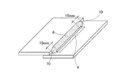
- FIG. 3 is a perspective view schematically showing the weld bead toe and the start and end of the weld bead formed by the lap fillet welding of FIG. 1 .
- FIG. 4 is a perspective view schematically showing a welded portion in the arc welded joint of the present invention.
- FIG. 5 is a cross-sectional view of the arc welded joint shown in FIG. 4 taken along the line AA, schematically showing the weld bead toe and its surroundings.
- FIG. 6 is a graph showing an example of a pulse current waveform supplied as a welding current.
- FIG. 7 is a graph showing the relationship between the Vickers hardness of the weld zone, the slag coverage area ratio, and the ratio of the joint tensile strength to the base metal tensile strength.
- the arc welded joint and arc welding method of the present invention will be described with reference to FIGS.
- an embodiment in which the present invention is applied to lap fillet welding will be described.
- the present invention is not limited to lap fillet welding, but is applicable to various welding techniques (eg, butt welding, etc.).
- FIG. 1 to 3 show an example of lap fillet welding of two steel plates by arc welding.
- the welding wire 1 and the steel plate 3 continuously fed from the welding torch 2 through the center of the welding torch 2 to the steel plate 3 are used as electrodes, and the welding power source ( (not shown) to apply a welding voltage.
- the above-mentioned “from the welding torch 2 to the steel plate 3” specifically refers to "from the welding torch 2 to the weld line formed by the corner portion 4 of the step formed by stacking two base metal steel plates 3". .
- a portion of the shielding gas (not shown) supplied from within the welding torch 2 is ionized and turned into plasma, thereby forming an arc 5 between the welding wire 1 and the steel plate 3 .
- the thermal energy of the arc 5 melts the tip of the welding wire 1 to form a droplet, and the droplet is transported to the molten pool by electromagnetic force, gravity, or the like. This phenomenon occurs continuously with the movement of the welding torch 2 or the steel plate 3 , so that the molten pool solidifies behind the weld line and a weld bead 6 is formed. This achieves the joining of the two steel plates.
- the present invention focuses on defining the Vickers hardness distribution of the weld metal (see FIG. 5) in the weld zone. Specifically, when the minimum value of the Vickers hardness of the weld metal described later is H min and the average value of the Vickers hardness of the softened portion of the weld heat affected zone (HAZ) is H HAZ , H min ⁇ 1.07. By satisfying the relationship xH HAZ , the stress concentration in the weld metal can be relaxed. However, even if the Vickers hardness of the weld metal is high, cracks may easily occur.
- H max ⁇ 550 is defined, where H max is the maximum value of the Vickers hardness of the weld metal, which will be described later. It was found that by setting the Vickers hardness distribution within an appropriate range as described above, breakage in the weld metal can be suppressed.
- the present invention by defining the Vickers hardness distribution of the weld metal of the weld zone as described above, even when a tensile load is applied in a direction perpendicular to the weld line, the stress concentration in the weld metal is alleviated, As a result, the inventors have found that breakage at the weld metal can be suppressed.
- welding wire 1 and steel plate 3 to which non-ferrous elements such as Si, Mn and Ti are added as a deoxidizing agent are used. That is, the reaction between oxygen and iron is suppressed by discharging the oxygen generated by the reaction of formula (6) or (7) as slag made of SiO 2 , MnO, TiO 2 and the like.
- the chemical conversion treatment layer made of zinc phosphate crystals in the slag region, which is an insulator is not formed.
- the formation of the coating film is insufficient, and the adhesion of the coating film is insufficient, resulting in a significant decrease in corrosion resistance.
- the plate thickness is reduced due to the progress of rusting and corrosion. Therefore, it is necessary to suppress the formation of slag while preventing deterioration of the mechanical performance of the weld metal by using the welding wire 1 and the steel plate 3 to which a deoxidizing agent is added.
- the oxidizing gas contained in the shielding gas is specified in order to suppress the slag generation reaction (oxidation reaction) without reducing the additive elements that ensure the mechanical performance of the weld metal.
- the slag generation reaction oxidation reaction
- coating film defects in electrodeposition coating can be reduced, thereby improving corrosion resistance and preventing the development of rust and corrosion even in a corrosive environment.
- the present invention by specifying the oxidizing gas contained in the shield gas as described above, the amount of O 2 and CO 2 mixed in is reduced, and as a result, the slag that adheres to the weld, especially the weld toe Suppresses the generation of The present inventors have found that this can suppress the formation of rust and the decrease in joint strength due to corrosion.
- the term "bead start/end” in the present invention refers to a region including a bead start and a bead end.
- the “bead start” is the area from the bead start (welding start position) to the bead end (weld end position) on the weld line up to 15 mm
- the “bead end” is the area from the bead end to the weld line It is an area up to 15 mm in the direction of the starting end.
- the term "bead toe” refers to the boundary between the weld metal in the direction perpendicular to the weld line of the weld bead 6 and the unmelted base steel plate.
- a “weld line” refers to a line parallel to the welding direction of the weld bead 6 .
- FIG. 4 shows a perspective view of the weld bead 6 of the arc welded joint formed by the lap fillet welding of FIG.
- FIG. 5 shows a partially enlarged view of the AA line cross section of the arc welded joint shown in FIG. 4 as viewed from the front.
- the arc-welded joint of the present invention is an arc-welded joint in which at least two steel plates are overlapped and arc-welded as described above.
- the area of the surface of the weld bead in the weld is the bead surface area S BEAD (mm 2 )
- the area of the area of the bead surface area S BEAD covered with slag is the slag surface area S SLAG (mm 2 ).
- the slag coverage area ratio S RATIO (%) calculated by the formula (1) is 20% or less, and the maximum value of the Vickers hardness of the weld metal in the weld zone is Hmax , and the Vickers hardness of the weld metal is
- the minimum value of the hardness is H min and the average value of the Vickers hardness of the softened part of the weld heat affected zone (HAZ) is H HAZ
- the Vickers hardness of the softened part of the weld metal and the weld heat affected zone is H max ⁇ 550 and H min ⁇ 1.07 ⁇ H HAZ .
- S RATIO 100 ⁇ S SLAG /S BEAD (1)
- the slag covering area ratio S RATIO (%) calculated by the formula (1) is 20% or less. If the slag 11 generated during welding adheres to the surface of the weld bead 6 with a covering area ratio of more than 20%, even if the arc welded joint is subjected to chemical conversion treatment, the chemical conversion treatment layer will not be sufficiently formed, and electrodeposition coating will not be performed. Even if it is applied, poor formation of the coating film and deterioration of adhesion of the coating film occur.
- the slag coverage area ratio S RATIO is preferably 15% or less, more preferably 10% or less.
- bead surface area S BEAD refers to the surface area of the weld bead 6 , which is the area where the molten metal solidifies including the bead toe of the weld, as shown in FIG. 4 .
- slag surface area S SLAG refers to the total area of the regions of the weld bead 6 covered with the slag 11, as shown in FIG.
- the bead surface area S BEAD and the slag surface area S SLAG can be determined by the following method, as described in Examples below. Specifically, the surface of the weld bead 6 in the area excluding the bead start and end portions 10 (each having a length of 15 mm) of the weld bead 6 is photographed from directly above, and the obtained photographed image is used to determine the weld bead and slag. The projected area from the top surface is measured, and the bead surface area S BEAD and the slag surface area S SLAG are calculated respectively.
- the slag coverage area ratio S RATIO is preferably 0.1% or more, more preferably 0.5% or more, and even more preferably 1.0% or more.
- Vickers hardness in weld metal and softened portion of HAZ H max ⁇ 550 and H min ⁇ 1.07 ⁇ H HAZ If the Vickers hardness of the weld metal and the softened portion of the HAZ does not satisfy H max ⁇ 550, excessive hardening tends to cause cracks in the weld metal. Further, if the Vickers hardness of the above region does not satisfy H min ⁇ 1.07 ⁇ H HAZ , stress concentration occurs in the weld metal, and fracture may occur in the weld metal. Therefore, in the present invention, the Vickers hardness of the weld metal and the softened portion of the HAZ shall satisfy both H max ⁇ 550 and H min ⁇ 1.07 ⁇ H HAZ .
- the maximum value Hmax of the Vickers hardness of the weld metal is preferably 520 or less, more preferably 450 or less, still more preferably 400 or less.
- the minimum Vickers hardness Hmin of the weld metal is preferably 220 or more, more preferably 240 or more.
- the Vickers hardness of the above region is preferably H min ⁇ 1.10 ⁇ H HAZ .
- the Vickers hardness of the above region is preferably 1.35 ⁇ H HAZ ⁇ H min .
- the maximum value H max of the Vickers hardness of the weld metal is preferably 250 or more, more preferably 270 or more, and still more preferably 290 or more.
- the minimum Vickers hardness Hmin of the weld metal is preferably 500 or less, more preferably 400 or less, and even more preferably 350 or less.
- the "weld metal” is a solidified region in which the molten welding wire and the base material are mixed.
- the “softened zone of HAZ” refers to a region of the heat affected zone (HAZ) in which the hardness becomes lower than the hardness of the base material steel plate due to reheating during welding.
- the HAZ softened portion is a region indicated by a grid pattern in the example shown in FIG.
- the “maximum value H max of the Vickers hardness of the weld metal” refers to the maximum value H max of the Vickers hardness in the weld metal region within the Vickers hardness measurement range described below.
- the “minimum value H min of the Vickers hardness of the weld metal” refers to the minimum value H min of the Vickers hardness in the weld metal region within the Vickers hardness measurement range.
- the average value of the Vickers hardness of the softened portion of the weld heat affected zone (HAZ) is H HAZ " refers to the average value of the Vickers hardness in the HAZ softened area in the Vickers hardness measurement range.
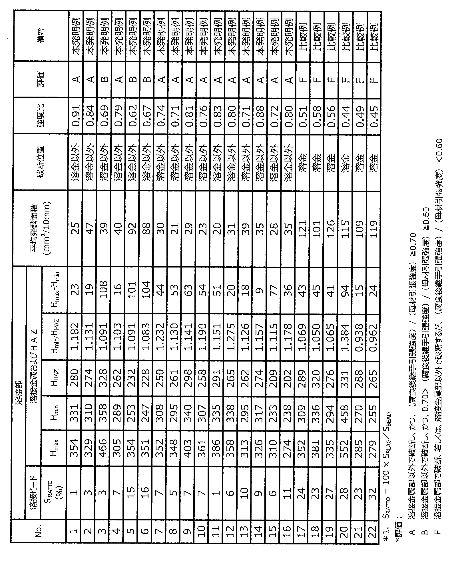
- the Vickers hardness (H max , H min , H HAZ ) in the softened portion of the weld metal and HAZ can be obtained by the following method, as described in Examples below. Specifically, the Vickers hardness of the weld metal is measured by 0.2 mm in the plate thickness direction from the surface of the steel plate on the weld toe side in the plate thickness direction cross section perpendicular to the weld line, as shown in FIG. and a range of 20 mm from the weld toe to the base metal in the direction perpendicular to the plate thickness (this is referred to as the "Vickers hardness measurement range"). In the case of the example shown in FIG.
- the Vickers hardness measurement range is on the dotted line (Vickers hardness measurement line) shown in FIG. 5, and this measurement range is measured under the following conditions.
- a Vickers hardness test described in JIS Z 2244 is performed at a measurement interval of 0.2 mm and a measurement load of 200 g to determine the maximum value H max and minimum value H min of the Vickers hardness of the weld metal region.
- the average value of the Vickers hardnesses in the softened portion of the HAZ is obtained, and the representative Vickers hardness H HAZ of the softened portion of the HAZ is obtained.
- FIG. 7 shows a graph showing the relationship between the Vickers hardness of the weld zone, the slag coverage area ratio, and the ratio of the joint tensile strength to the base metal tensile strength. As shown in FIG. 7, the joint strength can be improved by appropriately controlling not only the Vickers hardness but also the Vickers hardness and the slag coverage area ratio.
- the variation in the Vickers hardness of the weld metal in the welded portion excluding the region (bead start and end portion 10) up to 15 mm from the bead start and end of the weld bead 6 is set to a predetermined value. is preferably controlled to be within the range of
- H max ⁇ H min The maximum value of the Vickers hardness of the weld metal in the cross section perpendicular to the line (weld line) parallel to the welding direction of the weld bead 6 was defined as Hmax , and the minimum value of the Vickers hardness of the weld metal was defined as Hmin.
- H max ⁇ H min the maximum and minimum values of Vickers hardness preferably satisfy the relationship H max ⁇ H min ⁇ 100.
- H max ⁇ H min The lower limit of the difference between the maximum and minimum values of Vickers hardness of the weld metal is not specified.
- H max ⁇ H min is preferably 0.1 or more, more preferably 1 or more.
- the steel plate used for the arc-welded joint of the present invention is preferably a high-strength steel plate having a tensile strength of 440 MPa or more.
- the upper limit of the tensile strength of the steel sheet is not particularly specified. From the viewpoint of application to automobile members, the tensile strength is preferably 1200 MPa or less.
- the welding conditions for arc welding are controlled as follows. is important.
- the shielding gas is composed of Ar gas and an oxidizing gas, and the oxidizing gas satisfies the relationship of formula (2). 2 ⁇ [O 2 ]+[CO 2 ] ⁇ 5 (2)
- [O 2 ] is the volume % of O 2 in the shielding gas
- [CO 2 ] is the volume % of CO 2 in the shielding gas.
- the welding wire 1 becomes the anode and the steel plate 3 becomes the cathode (see Fig. 1).
- a welding voltage is applied from the welding wire 1 continuously supplied to the steel plate 3 through the center of the welding torch 2, and part of the shielding gas supplied from within the welding torch 2 is ionized and turned into plasma. .
- An arc 5 is thereby formed between the welding wire 1 and the steel plate 3 .
- the remainder of the shielding gas isolates the arc 5, the molten metal 7 and the molten pool 8 from the atmosphere (see Figure 2). This serves to prevent oxygen contamination (ie, slag generation) and nitrogen contamination (ie, blowhole generation).
- the tip of the welding wire 1 is melted by the thermal energy of the arc 5 to become the molten metal 7, and the droplets are transported to the molten pool 8 by electromagnetic force and gravity.
- the state in which the molten metal 7 is separated from the molten pool 8 (see FIG. 2A) and the state in which the molten metal 7 contacts the molten pool 8 and is electrically short-circuited (see FIG. 2B) ) are repeated regularly.
- the molten pool 8 solidifies behind the weld line and a weld bead 6 is formed.
- the effect of preventing slag generation can be obtained.
- a higher Vickers hardness can be stably obtained by suppressing the reduction of alloying elements such as Si and Mn due to deoxidation reaction.
- the “shielding gas” in the welding conditions described above is a shielding gas composed of Ar gas and an oxidizing gas, and the oxidizing gas has the relationship of formula (2) shall be satisfied.
- the value of the left side of the formula (2) that is, the value calculated by (2 ⁇ [O 2 ]+[CO 2 ])
- the value of the left side of equation (2) exceeds 5
- oxygen mixed in the molten metal 7 and the molten pool 8 increases.
- the slag deposition on the weld bead surface increases.
- the chemical conversion treatability and electrodeposition coatability deteriorate. Therefore, the value of the left side of equation (2) is set to 5 or less. Preferably 3 or less.
- the above effect can be obtained even with a shielding gas of 100% Ar gas. That is, the case where the value of the left side of the equation (2) is 0 is also included. Note that the condition of this "100% Ar gas" refers to an Ar purity of 99.99% or higher.
- the weld bead 6 may tend to meander or may have a wavy shape.
- the welding wire 1 and the steel plate 3 are intermittently short-circuited, and the average value of the short-circuit frequency (hereinafter referred to as "short-circuit frequency”) and the short-circuit period (hereinafter , referred to as the "short-circuit period”) is preferably controlled as follows. Specifically, the average short-circuit frequency (average short-circuit frequency) F AVE (Hz) is set to 20 to 300 Hz, and the maximum short-circuit period (maximum short-circuit period) T CYC (s) is set to 1.5 s or less. is preferred.
- the reason why the welding wire 1 and the steel plate 3 in arc welding are intermittently short-circuited and the short-circuiting satisfies the predetermined conditions is as follows.
- the droplets generated from the tip of the welding wire 1 make the molten pool 8 unstable if the volume is too large or too small.
- the average short-circuit frequency F AVE is less than 20 Hz, large droplets move to the molten pool 8, and droplet transfer forms other than short-circuit transfer (for example, streaming transfer) are irregularly mixed. It will be done.
- the average short-circuit frequency F AVE exceeds 300 Hz, although the droplets are small, re-ignition of the arc due to the short circuit is excessive. For these reasons, the molten pool 8 is disturbed in any case, and it is difficult to eliminate meandering and waving of the weld bead.
- the average short-circuit frequency F AVE it is possible to make the volume of the droplet transported to the molten pool 8 by one short-circuit about the same as that of a sphere having the same diameter as the welding wire 1. becomes.
- the deposition amount can be made uniform, thereby stably obtaining an appropriate weld metal composition. Therefore, in the present invention, it is preferable to set the average short-circuit frequency F AVE (Hz) to 20 to 300 Hz.
- the average short-circuit frequency F AVE is more preferably 35 Hz or more, more preferably 35 Hz or more, from the viewpoint of eliminating unevenness in the volume of the droplets transported to the molten pool 8 by one short-circuit and improving the uniformity of the weld bead. is 45 Hz or higher, and more preferably 50 Hz or higher. Also, if the average short-circuit frequency F AVE is high, small-volume droplets may scatter as a large amount of spatter during short-circuiting and re-ignition. Therefore, the average short-circuit frequency F AVE is more preferably 250 Hz or less, more preferably 200 Hz or less, and even more preferably 190 Hz or less.
- the maximum short-circuit period T CYC exceeds 1.5 s, droplet transfer becomes unstable, resulting in unstable bead width and penetration depth. That is, by setting the maximum short-circuit period T CYC to 1.5 s or less, a weld bead 6 having a favorable shape can be obtained. Therefore, in the present invention, it is preferable to set the maximum short-circuit period T CYC to 1.5 seconds or less.
- the above “maximum short-circuit period T CYC " refers to the maximum value among the short-circuit periods of welding passes performed to obtain an arc welded joint. This means that the short circuit period of each welding pass does not exceed 1.5 s.
- the maximum short-circuit period T CYC is more preferably 1.0 s or less, more preferably 0.2 s or less, and 0.10 s. It is even more preferable to:
- the maximum short-circuit cycle T CYC of short-circuits may be within a range in which the average short-circuit frequency F AVE is 300 Hz or less, so the lower limit of the maximum short-circuit cycle T CYC is not particularly defined.
- the maximum short-circuit period T CYC is preferably 0.004 s or longer, more preferably 0.008 s or longer.
- the preferred range of welding conditions is, for example, average welding current: 150 to 300 A, average arc voltage: 20 to 35 V, welding speed: 30 to 200 cm / min, Ar gas flow rate: 10 to 25 Liters / min, contact tip and Distance from the base material (hereinafter referred to as "CTWD"): 5 to 30 mm.
- CTWD Distance from the base material
- the method of controlling the average short-circuit frequency and maximum short-circuit period within the above ranges is not particularly limited.
- the peak current of the pulse current is I PEAK (A)
- the base current is I BASE (A)
- the peak period is t PEAK (ms)
- the rising period is t UP (ms)
- the falling period is t DOWN.
- CTWD is L (mm)
- the value of X (A ⁇ s/m) calculated by Equation (3) is controlled to satisfy 50 ⁇ X ⁇ 250.
- X (I PEAK ⁇ t PEAK /L) + (I PEAK + I BASE ) ⁇ (t UP + t DOWN ) / (2 ⁇ L) (3)
- Expression (3) is an expression showing current waveform control by a pulse current as shown in FIG. If the value of X (A ⁇ s/m) calculated by the formula (3) is too small, the arc 5 may fluctuate and droplet transfer may become unstable. On the other hand, if the value of X is too large, the welding wire 1 may plunge into the molten pool 8, or the grown droplets may scatter during a short circuit, resulting in deterioration of the bead shape or spatter adhesion. Therefore, it is preferable to control the value of X so as to satisfy 50 ⁇ X ⁇ 250.
- the value of X is more preferably 60 or more, more preferably 80 or more.
- the value of X is more preferably 230 or less, more preferably 200 or less.
- “s" in the unit of X (A s/m) is second (seconds)
- the value of L is preferably 5 to 30 mm.
- the value of L is more preferably 8 mm or more, and more preferably 20 mm or less.
- the value of L is more preferably 10 mm or more, more preferably 18 mm or less.
- the value of I PEAK is preferably 250-600A.
- I PEAK is more preferably 400 A or more, more preferably 500 A or less.
- the value of I BASE is preferably 30 to 120A.
- I BASE is more preferably 40A or more, more preferably 100A or less.
- I BASE is more preferably 80A or less.
- the value of t PEAK is preferably 0.1 to 5.0 ms.
- t PEAK is more preferably 1.0 ms or more, and more preferably 4.0 ms or less.
- tPEAK is more preferably 1.2 ms or more, and more preferably 3.5 ms or less.
- the values of t UP and t DOWN are preferably 0.1 to 3.0 ms.
- Each of t UP and t DOWN is more preferably 0.5 ms or more and more preferably 2.5 ms or less. It is more preferably 0.8 ms or more, and more preferably 2.0 ms or less.
- t BASE is preferably 0.1 to 10.0 ms.
- t BASE is more preferably 1.0 ms or more, and more preferably 8.0 ms or less.
- t BASE is more preferably 1.5 ms or more, and more preferably 6.0 ms or less.
- the pulse frequency of the pulse current is not particularly limited as long as one short circuit can be generated with one pulse to several pulses.
- the purpose of defining the pulse current is (i) to promote stable droplet growth while suppressing arc fluctuation by keeping the current low in the base period, and (ii) from the peak period to the fall period.
- the electromagnetic force and the shearing force of the Ar shielding gas push the grown droplets down into the molten pool instead of separating them from the wire, thereby promoting the short circuit.
- the arc welding method of the present invention does not require the supply of oxygen or the addition of special elements. Therefore, by using a solid wire, which is less expensive than a flux-cored wire, as the welding wire, the cost of the process can be reduced.
- the wire composition (component composition of the wire) of the solid wire is not particularly limited.
- Such a wire composition can be applied to arc welding of a wide range of steel types from mild steel to ultra-high tensile strength steel by appropriately adjusting the composition.
- the solid wire preferably has a diameter of 0.4 mm to 2.0 mm.
- C 0.020 to 0.150% by mass
- C is an element necessary to ensure the strength of the weld metal, and has the effect of reducing the viscosity of the molten metal and improving the fluidity.
- the C content is less than 0.020% by mass, the strength of the weld metal cannot be ensured.
- the C content exceeds 0.150% by mass, the toughness of the weld metal is lowered. Therefore, the C content is preferably 0.020-0.150% by mass.
- the C content is more preferably 0.050% by mass or more, and more preferably 0.10% by mass or less.
- Si 0.20 to 1.00% by mass
- Si is an element that, while having a deoxidizing effect, enhances the hardenability of the weld metal when added in an appropriate amount, and contributes to improving the toughness and strength of the weld metal.
- a deoxidizing action by Si is not particularly necessary, but if the Si content is less than 0.20% by mass, droplets and molten pools oscillate during welding, generating a large amount of spatter.
- the Si content exceeds 1.00% by mass, the toughness of the weld metal is lowered. Therefore, the Si content is preferably 0.20 to 1.00% by mass.
- the Si content is more preferably 0.30% by mass or more, and more preferably 0.90% by mass or less.
- Mn 0.50 to 2.50% by mass
- Mn is an element that has a deoxidizing effect like Si and improves the mechanical properties of the weld metal.
- the Mn content is less than 0.50% by mass, the amount of Mn remaining in the weld metal is insufficient and sufficient strength and toughness cannot be obtained.
- the Mn content exceeds 2.50% by mass, the toughness of the weld metal is lowered. Therefore, the Mn content is preferably 0.50-2.50% by mass.
- the Mn content is more preferably 0.80% by mass or more, and more preferably 1.80% by mass or less.
- P 0.020% by mass or less
- P is an element that is mixed as an impurity in steel during the steelmaking process and the casting process, and is an element that reduces the hot cracking resistance of the weld metal, and is preferably reduced as much as possible. .
- the P content is preferably 0.020% by mass or less.
- the P content is more preferably 0.010% by mass or less. From the viewpoint of hot cracking resistance of the weld metal, the lower limit of the P content is not particularly specified, and 0% by mass is also included.
- the P content is preferably 0.001% by mass or more.
- S 0.03% by Mass or Less
- S is an impurity that is unavoidably contained in the steel wire, and is an element that lowers the hot cracking resistance of the weld metal, and is preferably reduced as much as possible.
- the S content is preferably 0.03% by mass or less.
- the S content is more preferably 0.015% by mass or less.
- the lower limit of the S content is not particularly specified, and 0% by mass is also included.
- the S content is preferably 0.001% by mass or more.
- the solid wire may also contain one or more selected from Ni, Cr, Ti, and Mo as needed.
- Ni is an element that increases the strength of the weld metal and improves weather resistance. However, if the Ni content is less than 0.02% by mass, such an effect cannot be obtained. On the other hand, when the Ni content exceeds 3.50% by mass, the toughness of the weld metal is lowered. Therefore, when Ni is added, the Ni content is preferably 0.02 to 3.50% by mass.
- Cr is an element that increases the strength of the weld metal and improves weather resistance. However, if the Cr content is less than 0.01% by mass, such effects cannot be obtained. On the other hand, when the Cr content exceeds 1.50% by mass, the toughness of the weld metal is lowered. Therefore, when Cr is added, the Cr content is preferably 0.01 to 1.50% by mass.
- Ti is an element that acts as a deoxidizing agent and improves the strength and toughness of the weld metal. Ti also has the effect of stabilizing the arc and reducing spatter. However, if the Ti content exceeds 0.15% by mass, the droplets become coarse during welding, resulting not only in the generation of large spatter, but also in the toughness of the weld metal. Therefore, when Ti is added, the Ti content is preferably 0.15% by mass or less.
- Mo is an element that improves the strength of the weld metal, but if its content exceeds 0.8% by mass, the toughness of the weld metal decreases. Therefore, when adding Mo, as for Mo content, 0.8 mass % or less is preferable.
- the balance of the wire composition of solid wires is Fe and incidental impurities.
- N and Cu are mentioned as an unavoidable impurity of wire composition.
- N is an impurity that is unavoidably mixed in at the stage of melting the steel material and the stage of manufacturing the steel wire, and adversely affects the toughness of the weld metal. Therefore, it is preferable to suppress the N content to 0.01% by mass or less.
- Cu is an impurity that is unavoidably contained in the steel wire, and is an element that reduces the toughness of the weld metal. In particular, when the Cu content exceeds 3.0% by mass, the toughness of the weld metal is remarkably lowered. Therefore, the Cu content is preferably 3.0% by mass or less.
- the Vickers hardness distribution in the welded portion of a steel member is defined, and the amount of slag adhered to the welded portion is reduced to suppress rusting, thereby progressing corrosion. It is possible to improve the joint strength of the welded portion even in a harsh environment. In particular, by reducing the amount of slag adhered, the chemical conversion treatability and the electrodeposition coating property of the weld zone are improved. In addition to this, it is possible to suppress the reduction of alloying elements such as Si and Mn due to the deoxidation reaction, so that a higher Vickers hardness can be stably obtained. As a result, stable joint strength can be obtained even in corrosive environments.
- a high-strength steel sheet having a tensile strength of 440 MPa or more e.g., steel sheets of 440 MPa, 590 MPa, and 980 MPa grades
- a high-strength steel plate By using such a high-strength steel plate, it is possible to reduce the thickness of the member.
- the thickness of the high-strength steel sheet is preferably 0.8 to 4 mm because the present invention is suitably used for automobile members and the like.
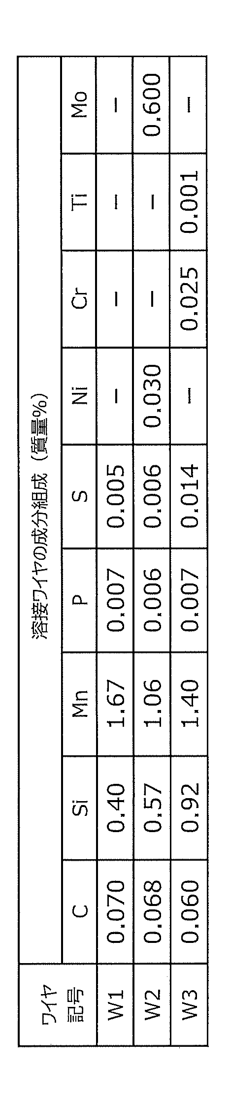
- the welding wire shown as "wire symbol” in Table 2 had a wire composition shown in Table 4 and was a solid wire with a diameter of 1.2 mm. Components other than the "component composition of welding wire” shown in Table 4 are Fe and unavoidable impurities.
- the wire symbol "W1" shown in Table 4 contains 0.005% by mass of N and 0.27% by mass of Cu as inevitable impurities in the wire composition.
- Alkali degreasing, surface conditioning, and zinc phosphate-based chemical conversion treatment were performed using the produced arc welded joint, and cationic electrodeposition coating was performed under the conditions that the film thickness of the flat plate portion of the base material other than the welded portion was 15 ⁇ m. After that, the SAE J2334 corrosion test was performed up to 60 cycles.
- the shape of the weld bead after welding was evaluated as follows.
- the bead surface area S BEAD and the slag surface area S SLAG were obtained by photographing the surface of the weld bead 6 in the area excluding the bead start and end 10 (each length: 15 mm) from directly above (magnification: 5 times). Using the captured images, the projected area of the weld bead and slag from the upper surface was measured and calculated. At this time, when the length of the weld bead 6 was less than 130 mm, the surface of the entire length excluding the bead start/end portion 10 was photographed.
- the surface of the weld bead 6 was photographed at an arbitrary site (length 100 mm) excluding the bead start/end portion 10 . Moreover, slag with a total length of 0.5 mm or less was excluded from the calculation. As shown in FIGS. 4 and 5, the surface area of the weld bead 6 photographed above was defined as the bead surface area S BEAD (mm 2 ). Of this bead surface area S BEAD , the sum of the areas covered with the slag 11 was defined as the slag surface area S SLAG (mm 2 ). Using the calculated values of the bead surface area S BEAD and the slag surface area S SLAG and the above equation (1), the slag covering area ratio S RATIO was obtained. Table 3 shows the obtained slag coverage ratio S RATIO .
- the joint tensile strength was measured by the following method. First, the arc-welded joint after the corrosion test was immersed in a stripping agent for immersion to strip the electrodeposition coating, and then the corrosion products were removed in accordance with ISO8407. Then, a tensile test piece according to JIS Z 2241 was obtained by machining. As a tensile test for the prepared tensile test piece, a tensile test was performed at a tensile speed of 10 mm/min at room temperature, and the joint tensile strength was recorded. This value was taken as the post-corrosion joint tensile strength.
- the cross section of the fractured test piece was polished and subjected to nital corrosion, and then the cross section was photographed with an optical microscope (10x magnification) to determine the fracture position.
- the base material tensile strength was measured by the following method.
- a tensile test piece according to JIS Z 2241 was obtained by machining from a base material steel plate having a size (for example, 200 mm x 300 mm x plate thickness) that allows sufficient extraction of a tensile test piece.
- a tensile test for the prepared tensile test piece a tensile test was performed at a tensile speed of 10 mm/min at room temperature, and the joint tensile strength was recorded. This value was taken as the base material tensile strength.
- the evaluation of "rust prevention" shown in Table 3 was performed as follows. For the welded joint after the accelerated corrosion test, the surface of the weld bead 6 in the area excluding the bead start and end 10 (each length 15 mm) of the weld bead 6 was photographed from directly above (see FIG. 3), and the unit An average rusted area per length (mm 2 /10 mm) was calculated. The values obtained are shown in Table 3.
- the evaluation of rust prevention was based on the following criteria. When the average rusted area was greater than 95 (mm 2 /10 mm) and 100 (mm 2 /10 mm) or less, it was evaluated that the rust prevention effect after corrosion was excellent.
- the average rusted area was greater than 50 (mm 2 /10 mm) and 95 (mm 2 /10 mm) or less, it was evaluated that the post-corrosion rust prevention effect was superior. Furthermore, when the average rusted area was 50 (mm 2 /10 mm) or less, it was evaluated that the rust prevention effect after corrosion was further excellent.
- welding Nos. 1 to 16 shown as examples of the present invention have an S RATIO of 20% or less, and satisfy the relationship of H max ⁇ 550 and H min ⁇ 1.07 ⁇ H HAZ . fulfilled. As a result, an arc welded joint was obtained which was able to prevent rusting and had excellent joint strength.
- the above effect can be obtained by using either the welding wire for ultra high tensile strength (wire symbols W1 and W2 in Table 4) or the welding wire for mild steel (wire symbol W3 in Table 4). I was able to confirm that I have.
- the graph in FIG. 7 shows the relationship between the Vickers hardness of the weld zone, the slag coverage area ratio, and the ratio of the joint tensile strength to the base metal tensile strength (strength ratio) in this example.
- the joint strength was further improved by controlling the two factors of the Vickers hardness and the slag coating area ratio, compared to the case of controlling only the Vickers hardness.
Landscapes
- Engineering & Computer Science (AREA)
- Mechanical Engineering (AREA)
- Physics & Mathematics (AREA)
- Plasma & Fusion (AREA)
- Chemical & Material Sciences (AREA)
- Materials Engineering (AREA)
- Arc Welding In General (AREA)
- Butt Welding And Welding Of Specific Article (AREA)
- Arc Welding Control (AREA)
Abstract
Description
[1] 少なくとも2枚の鋼板を重ねてアーク溶接された溶接部を有するアーク溶接継手であって、
前記溶接部における溶接ビードの表面の面積をビード表面積SBEAD(mm2)、前記ビード表面積SBEADのうちのスラグで覆われた領域の面積をスラグ表面積SSLAG(mm2)としたとき、(1)式で算出されるスラグ被覆面積率SRATIO(%)が20%以下であり、
前記溶接部における溶接金属のビッカース硬さの最大値をHmax、溶接金属のビッカース硬さの最小値をHmin、溶接熱影響部の軟化部のビッカース硬さの平均値をHHAZとしたとき、前記溶接金属および前記溶接熱影響部の軟化部におけるビッカース硬さが、Hmax≦550かつHmin≧1.07×HHAZの関係を満たす、アーク溶接継手。
SRATIO=100×SSLAG/SBEAD …(1)
[2] 前記溶接金属のビッカース硬さの最大値および前記溶接金属のビッカース硬さの最小値が、Hmax-Hmin≦100の関係を満たす、[1]に記載のアーク溶接継手。
[3] [1]または[2]に記載のアーク溶接継手を得るためのアーク溶接方法であって、
少なくとも2枚の鋼板を重ねてアーク溶接して溶接部を形成するに際し、
Arガスおよび酸化性ガスからなり、かつ、前記酸化性ガスが(2)式の関係を満たすシールドガスを使用する、アーク溶接方法。
2×[O2]+[CO2]≦5 …(2)
ただし、[O2]はシールドガス中のO2の体積%であり、[CO2]はシールドガス中のCO2の体積%である。
[4] 前記アーク溶接では、前記鋼板と溶接ワイヤが断続的に短絡し、
前記短絡の平均短絡周波数FAVE(Hz)が20~300Hzであり、かつ前記短絡の最大短絡周期TCYC(s)が1.5s以下である、[3]に記載のアーク溶接方法。
[5] 前記アーク溶接では溶接電流としてパルス電流を使用し、
前記パルス電流のピーク電流をIPEAK(A)、ベース電流をIBASE(A)、ピーク期間をtPEAK(ms)、立ち上がり期間をtUP(ms)、立ち下がり期間をtDOWN(ms)、および前記鋼板とコンタクトチップとの距離をL(mm)としたとき、(3)式で算出されるX(A・s/m)の値が50≦X≦250を満たす、[3]または[4]に記載のアーク溶接方法。
X=(IPEAK×tPEAK/L)+(IPEAK+IBASE)×(tUP+tDOWN)/(2×L)…(3)
[6] 前記アーク溶接では、溶接ワイヤとしてソリッドワイヤを使用する、[3]~[5]のいずれか1つに記載のアーク溶接方法。
[7] 前記アーク溶接は逆極性で行う、[3]~[6]のいずれか1つに記載のアーク溶接方法。
O2→2[O] …(6)
CO2→CO+[O] …(7)
このような分解反応で生成した酸素は、溶融メタル7や溶融池8に溶解(図2(A)および図2(B)を参照)し、冷却されて溶接金属として凝固する際に、気泡となって溶接金属内に残留する。また、酸素と鉄の酸化反応が進行して、溶接金属の機械的性能を劣化させる場合がある。
図4には、図1の重ね隅肉溶接で形成されるアーク溶接継手の溶接ビード6の斜視図を示す。図5には、図4に示すアーク溶接継手のA-A線断面を正面視した一部拡大図を示す。
SRATIO=100×SSLAG/SBEAD …(1)
図4に示すように、溶接部の溶接ビード6の表面の面積をビード表面積SBEAD(mm2)とし、ビード表面積SBEADのうちのスラグ11で覆われた領域の面積をスラグ表面積SSLAG(mm2)としたとき、(1)式で算出されるスラグ被覆面積率SRATIO(%)が20%以下である。溶接時に生成するスラグ11がその被覆面積率20%を超えて溶接ビード6の表面に付着すると、アーク溶接継手を化成処理に供しても、化成処理層が十分に形成されず、電着塗装を施しても塗膜の形成不良や、塗膜の密着性低下が生じる。このため、腐食環境下での発錆および減肉が容易となり、その結果、継手強度が低下する場合がある。スラグの生成量が減少すると溶接ビード6の表面におけるスラグ11の凝集が抑制されるため、化成処理性および電着塗装性が向上し、腐食による継手強度の低下の抑制につながる。そのため、スラグ被覆面積率SRATIOは、好ましくは15%以下とし、より好ましくは10%以下とする。
溶接金属およびHAZの軟化部におけるビッカース硬さが、Hmax≦550を満たさない場合、過度の硬化によって溶接金属において割れが生じやすくなる。また、上記した領域のビッカース硬さがHmin≧1.07×HHAZを満たさない場合、溶接金属において応力集中が発生し、溶接金属での破断が生じる場合がある。したがって、本発明では、溶接金属およびHAZの軟化部におけるビッカース硬さが、Hmax≦550およびHmin≧1.07×HHAZの両方を満たすものとする。溶接金属のビッカース硬さの最大値Hmaxは、好ましくは520以下とし、より好ましくは450以下とし、さらに好ましくは400以下とする。溶接金属のビッカース硬さの最小値Hminは、好ましくは220以上とし、より好ましくは240以上とする。
また、上記した領域のビッカース硬さは、Hmin≧1.10×HHAZとすることが好ましい。上記した領域のビッカース硬さは、1.35×HHAZ≧Hminとすることが好ましい。
そこで、本発明では、図4に示すように、溶接ビード6のビード始終端からそれぞれ15mmまでの領域(ビード始終端部10)を除いた溶接部における溶接金属のビッカース硬さのばらつきを、所定の範囲内となるように制御することが好ましい。
溶接ビード6の溶接方向に平行な線(溶接線)に垂直な方向の断面での溶接金属のビッカース硬さの最大値をHmaxとし、溶接金属のビッカース硬さの最小値をHminとしたとき、該ビッカース硬さの最大値および最小値が、Hmax-Hmin≦100の関係を満たすことが好ましい。溶接金属のビッカース硬さのばらつきを小さくする(すなわちHmaxとHminの差を小さくする)ことによって、応力集中を緩和することができる。その結果、継手強度に優れたアーク溶接継手を得ることができる。(Hmax-Hmin)は、より好ましくは80以下とし、さらに好ましくは50以下とし、さらに一層好ましくは40以下とする。
該鋼板の引張強度の上限は特に規定しない。自動車用部材に適用する観点からは、引張強度は1200MPa以下とすることが好ましい。
2×[O2]+[CO2]≦5 …(2)
ここで、(2)式において、[O2]はシールドガス中のO2の体積%であり、[CO2]はシールドガス中のCO2の体積%である。
本発明では、100%Arガスのシールドガスでも上述の効果を得られる。すなわち、(2)式の左辺の値が0の場合も含まれる。なお、この「100%Arガス」の条件として、Ar純度が99.99%以上のものを指す。
上記の「平均短絡周波数FAVE」とは、アーク溶接継手を得るために行なう溶接パスの短絡周波数の平均値を指す。よって、溶接パスのアーク電圧の推移を測定機器(たとえばオシロスコープ等)で測定し、そのアーク電圧がゼロになる回数を計測し、その溶接に要した時間(s)で回数を除した値(回/s=Hz)が、「平均短絡周波数」である。
上記の「最大短絡周期TCYC」とは、アーク溶接継手を得るために行なう溶接パスの短絡周期の中の最大値を指す。すなわち、溶接パスの各々の短絡周期が、いずれも1.5sを超えないことを意味する。
X=(IPEAK×tPEAK/L)+(IPEAK+IBASE)×(tUP+tDOWN)/(2×L)…(3)
(3)式で算出されるX(A・s/m)の値が小さすぎると、アーク5のふらつきや溶滴移行の不安定化が発生する場合がある。一方、Xの値が大きすぎると、溶接ワイヤ1が溶融池8へ突っ込んだり、成長した溶滴が短絡時に飛散して、ビード形状の劣化やスパッタ付着などを生じる場合がある。したがって、Xの値は、50≦X≦250を満たすように制御することが好ましい。Xの値は、より好ましくは60以上とし、さらに好ましくは80以上とする。Xの値は、より好ましくは230以下とし、さらに好ましくは200以下とする。
なお、Xの単位(A・s/m)中の「s」はセカンド(秒)であり、tPEAK、tUP、tDOWNの単位の「ms」は、ミリセカンド(=1/1000秒)である。
Cは、溶接金属の強度を確保するのに必要な元素であり、溶融メタルの粘性を低下させて流動性を向上させる効果がある。しかし、C含有量が0.020質量%未満では、溶接金属の強度を確保できない。一方、C含有量が0.150質量%を超えると、溶接金属の靭性が低下する。したがって、C含有量は0.020~0.150質量%が好ましい。C含有量は、より好ましくは0.050質量%以上であり、より好ましくは0.10質量%以下である。
Siは、脱酸作用を有する一方で、適当量の添加によって溶接金属の焼入れ性を高め、溶接金属の靭性、強度向上に寄与する元素である。MIG溶接ではArシールドガスによって溶接金属への酸素の混入を抑制することができる。Siによる脱酸作用は特段必要ないが、Si含有量が0.20質量%未満では、溶接施工時に溶滴や溶融プールが揺動し、スパッタが多量に発生する。一方、Si含有量が1.00質量%を超えると、溶接金属の靭性が低下する。したがって、Si含有量は0.20~1.00質量%が好ましい。Si含有量は、より好ましくは0.30質量%以上であり、より好ましくは0.90質量%以下である。
Mnは、Siと同様に脱酸作用を有するとともに、溶接金属の機械的性質を向上させる元素である。しかし、Mn含有量が0.50質量%未満では、溶接金属中に残留するMn量が不足して十分な強度と靭性が得られない。一方、Mn含有量が2.50質量%を超えると、溶接金属の靭性が低下する。したがって、Mn含有量は0.50~2.50質量%が好ましい。Mn含有量は、より好ましくは0.80質量%以上であり、より好ましくは1.80質量%以下である。
Pは、製鋼工程および鋳造工程で鋼中に不純物として混入する元素であり、溶接金属の耐高温割れ性を低下させる元素であり、可能な限り減少させることが好ましい。とくに、P含有量が0.020質量%を超えると、溶接金属の耐高温割れ性が著しく低下する。したがって、P含有量は0.020質量%以下が好ましい。P含有量は、より好ましくは0.010質量%以下である。溶接金属の耐高温割れ性の観点から、P含有量の下限は特に規定せず、0質量%も含まれる。P含有量は、好ましくは0.001質量%以上とする。
Sは、鋼素線に不可避的に含有される不純物であり、溶接金属の耐高温割れ性を低下させる元素であり、可能な限り減少させることが好ましい。とくに、S含有量が0.03質量%を超えると、溶接金属の高温割れが発生し易くなる。したがって、S含有量は0.03質量%以下が好ましい。S含有量は、より好ましくは0.015質量%以下である。溶接金属の耐高温割れ性の観点から、S含有量の下限は特に規定せず、0質量%も含まれる。S含有量は、好ましくは0.001質量%以上とする。
なお、ワイヤ組成の不可避的不純物としてN、Cuが挙げられる。Nは、鋼材を溶製する段階や鋼素線を製造する段階で不可避的に混入する不純物であり、溶接金属の靭性に悪影響を及ぼす。このため、N含有量は0.01質量%以下に抑えることが好ましい。Cuは、鋼素線に不可避的に含有される不純物であり、溶接金属の靭性を低下させる元素である。特にCu含有量が3.0質量%を超えると、溶接金属の靭性が著しく低下する。このため、Cu含有量は3.0質量%以下が好ましい。
なお、本発明は、自動車用部材等に好適に用いられることから、高強度の鋼板の板厚は、0.8~4mmであることが好ましい。
ビード表面積SBEADとスラグ表面積SSLAGは、溶接ビード6のビード始終端部10(各々長さ15mm)を除いた領域における溶接ビード6の表面を真上から撮影し(倍率:5倍)、得られた撮影画像を用いて、溶接ビードおよびスラグの上面からの投影面積を測定して算出した。この際、溶接ビード6の長さが130mm未満である場合は、ビード始終端部10を除く全長の表面を撮影した。溶接ビード6の長さが130mm以上である場合は、ビード始終端部10を除いた任意の部位(長さ100mm)における溶接ビード6の表面を撮影した。また、全長0.5mm以下のスラグは除外して求めた。
図4および図5に示すように、上記撮影した溶接ビード6の表面積をビード表面積SBEAD(mm2)とした。このビード表面積SBEADのうち、スラグ11で覆われた領域の面積の合計をスラグ表面積SSLAG(mm2)とした。
算出したビード表面積SBEADおよびスラグ表面積SSLAGの値と、上記した(1)式とを用いて、スラグ被覆面積率SRATIOを求めた。求めたスラグ被覆面積率SRATIOを表3に示した。
溶接金属およびHAZのビッカース硬さの測定は、図5に示すように溶接線に垂直な板厚方向断面における、溶接止端部側の鋼板の表面から板厚方向に0.2mmの位置で、かつ、板厚と垂直方向に溶接止端部からそれぞれ母材にかけて20mmの範囲を測定して行った。図5に示す例の場合、図5中に示した点線(ビッカース硬さ測定線)の領域におけるビッカース硬さを測定した。まず、溶接ビード6のビード始終端部10(各々長さ15mm)を除いた領域(図4を参照)における、溶接ビード6の任意の箇所を溶接線に垂直な板厚方向に切断し、研磨を施した。次いで、測定間隔0.2mm、測定荷重200gで、JIS Z 2244に記載のビッカース硬さ試験を行い、溶接金属領域のビッカース硬さの最大値Hmaxおよび最小値Hminを求めた。HAZの軟化部のビッカース硬さは、HAZ軟化部領域(図5を参照)におけるビッカース硬さの平均値を求め、その平均値をHAZの軟化部の代表ビッカース硬さ(すなわち、HHAZ)とした。
求めた各ビッカース硬さ(Hmax、Hmin、HHAZ)を表3に示した。
腐食促進試験後の溶接継手に対して、溶接ビード6のビード始終端部10(各々長さ15mm)を除いた領域における溶接ビード6の表面を真上から撮影し(図3を参照)、単位長さ当たりの平均発錆面積(mm2/10mm)を算出した。得られた値を表3に示した。
ここでは、発錆防止の評価は以下の基準とした。
平均発錆面積が95(mm2/10mm)より大きく100(mm2/10mm)以下の場合に、腐食後の発錆防止効果が優れると評価した。また、平均発錆面積が50(mm2/10mm)より大きく95(mm2/10mm)以下の場合に、腐食後の発錆防止効果がより優れると評価した。さらに、平均発錆面積が50(mm2/10mm)以下の場合に、腐食後の発錆防止効果がさらに優れると評価した。


2 溶接トーチ
3 鋼板(母材)
4 段差のすみ部
5 アーク
6 溶接ビード
7 溶融メタル(溶滴)
8 溶融池
9 溶接ビード止端部
10 ビード始終端部
11 スラグ
Claims (7)
- 少なくとも2枚の鋼板を重ねてアーク溶接された溶接部を有するアーク溶接継手であって、
前記溶接部における溶接ビードの表面の面積をビード表面積SBEAD(mm2)、前記ビード表面積SBEADのうちのスラグで覆われた領域の面積をスラグ表面積SSLAG(mm2)としたとき、(1)式で算出されるスラグ被覆面積率SRATIO(%)が20%以下であり、
前記溶接部における溶接金属のビッカース硬さの最大値をHmax、溶接金属のビッカース硬さの最小値をHmin、溶接熱影響部の軟化部のビッカース硬さの平均値をHHAZとしたとき、前記溶接金属および前記溶接熱影響部の軟化部におけるビッカース硬さが、Hmax≦550かつHmin≧1.07×HHAZの関係を満たす、アーク溶接継手。
SRATIO=100×SSLAG/SBEAD …(1) - 前記溶接金属のビッカース硬さの最大値および前記溶接金属のビッカース硬さの最小値が、Hmax-Hmin≦100の関係を満たす、請求項1に記載のアーク溶接継手。
- 請求項1または2に記載のアーク溶接継手を得るためのアーク溶接方法であって、
少なくとも2枚の鋼板を重ねてアーク溶接して溶接部を形成するに際し、
Arガスおよび酸化性ガスからなり、かつ、前記酸化性ガスが(2)式の関係を満たすシールドガスを使用する、アーク溶接方法。
2×[O2]+[CO2]≦5 …(2)
ただし、[O2]はシールドガス中のO2の体積%であり、[CO2]はシールドガス中のCO2の体積%である。 - 前記アーク溶接では、前記鋼板と溶接ワイヤが断続的に短絡し、
前記短絡の平均短絡周波数FAVE(Hz)が20~300Hzであり、かつ前記短絡の最大短絡周期TCYC(s)が1.5s以下である、請求項3に記載のアーク溶接方法。 - 前記アーク溶接では溶接電流としてパルス電流を使用し、
前記パルス電流のピーク電流をIPEAK(A)、ベース電流をIBASE(A)、ピーク期間をtPEAK(ms)、立ち上がり期間をtUP(ms)、立ち下がり期間をtDOWN(ms)、および前記鋼板とコンタクトチップとの距離をL(mm)としたとき、(3)式で算出されるX(A・s/m)の値が50≦X≦250を満たす、請求項3または4に記載のアーク溶接方法。
X=(IPEAK×tPEAK/L)+(IPEAK+IBASE)×(tUP+tDOWN)/(2×L) …(3) - 前記アーク溶接では、溶接ワイヤとしてソリッドワイヤを使用する、請求項3~5のいずれか1項に記載のアーク溶接方法。
- 前記アーク溶接は逆極性で行う、請求項3~6のいずれか1項に記載のアーク溶接方法。
Priority Applications (6)
| Application Number | Priority Date | Filing Date | Title |
|---|---|---|---|
| MX2023012395A MX2023012395A (es) | 2021-04-28 | 2022-04-26 | Union soldada por arco y metodo de soldadura por arco. |
| KR1020237035561A KR20230154326A (ko) | 2021-04-28 | 2022-04-26 | 아크 용접 이음매 및 아크 용접 방법 |
| JP2022541948A JP7364088B2 (ja) | 2021-04-28 | 2022-04-26 | アーク溶接継手およびアーク溶接方法 |
| EP22795817.0A EP4306254A4 (en) | 2021-04-28 | 2022-04-26 | Arc-welded joint and arc-welding method |
| CN202280029303.9A CN117177831A (zh) | 2021-04-28 | 2022-04-26 | 电弧焊接头和电弧焊方法 |
| US18/287,348 US20240198447A1 (en) | 2021-04-28 | 2022-04-26 | Arc welded joint and arc welding method |
Applications Claiming Priority (2)
| Application Number | Priority Date | Filing Date | Title |
|---|---|---|---|
| JP2021076655 | 2021-04-28 | ||
| JP2021-076655 | 2021-04-28 |
Publications (1)
| Publication Number | Publication Date |
|---|---|
| WO2022230904A1 true WO2022230904A1 (ja) | 2022-11-03 |
Family
ID=83848455
Family Applications (1)
| Application Number | Title | Priority Date | Filing Date |
|---|---|---|---|
| PCT/JP2022/018950 Ceased WO2022230904A1 (ja) | 2021-04-28 | 2022-04-26 | アーク溶接継手およびアーク溶接方法 |
Country Status (7)
| Country | Link |
|---|---|
| US (1) | US20240198447A1 (ja) |
| EP (1) | EP4306254A4 (ja) |
| JP (1) | JP7364088B2 (ja) |
| KR (1) | KR20230154326A (ja) |
| CN (1) | CN117177831A (ja) |
| MX (1) | MX2023012395A (ja) |
| WO (1) | WO2022230904A1 (ja) |
Citations (6)
| Publication number | Priority date | Publication date | Assignee | Title |
|---|---|---|---|---|
| JPS61289978A (ja) * | 1985-06-14 | 1986-12-19 | Kawasaki Steel Corp | 鋼材のサブマ−ジア−ク溶接方法 |
| JP3905876B2 (ja) | 2003-10-01 | 2007-04-18 | 新日本製鐵株式会社 | 破壊形態に優れるアーク溶接重ね継手構造物 |
| JP2007119811A (ja) * | 2005-10-26 | 2007-05-17 | Sumitomo Metal Ind Ltd | 溶接継手及びその製造方法 |
| WO2013132550A1 (ja) * | 2012-03-07 | 2013-09-12 | パナソニック株式会社 | 溶接方法 |
| JP2013184216A (ja) * | 2012-03-09 | 2013-09-19 | Kobe Steel Ltd | ソリッドワイヤおよびこれを用いたガスシールドアーク溶接方法 |
| WO2018159404A1 (ja) * | 2017-02-28 | 2018-09-07 | Jfeスチール株式会社 | 重ね隅肉アーク溶接継手およびその製造方法 |
Family Cites Families (9)
| Publication number | Priority date | Publication date | Assignee | Title |
|---|---|---|---|---|
| JP5205115B2 (ja) * | 2008-04-16 | 2013-06-05 | 株式会社神戸製鋼所 | 純Arシールドガス溶接用MIGフラックス入りワイヤ及びMIGアーク溶接方法 |
| JP5515796B2 (ja) * | 2009-02-17 | 2014-06-11 | Jfeスチール株式会社 | 高強度薄鋼板の溶接方法 |
| JP6373550B2 (ja) * | 2011-03-31 | 2018-08-15 | Jfeスチール株式会社 | ガスシールドアーク溶接方法 |
| JP6373549B2 (ja) * | 2011-03-31 | 2018-08-15 | Jfeスチール株式会社 | ガスシールドアーク溶接方法 |
| JP5375981B2 (ja) * | 2012-01-10 | 2013-12-25 | Jfeスチール株式会社 | 耐溶接割れ性に優れた耐摩耗溶接鋼管およびその製造方法 |
| US11065705B2 (en) * | 2015-09-14 | 2021-07-20 | Nippon Steel Corporation | Fillet welding method and fillet welded joint |
| JP6594266B2 (ja) * | 2016-06-20 | 2019-10-23 | 株式会社神戸製鋼所 | ガスシールドアーク溶接方法及び溶接構造物の製造方法 |
| JP6285062B1 (ja) * | 2017-03-02 | 2018-02-28 | 日新製鋼株式会社 | 溶融Zn系めっき鋼板のアーク溶接方法および溶接部材の製造方法 |
| CN110605455A (zh) * | 2018-06-15 | 2019-12-24 | 天津大学 | 一种钛合金cmt—脉冲—热处理复合增材制造方法 |
-
2022
- 2022-04-26 US US18/287,348 patent/US20240198447A1/en active Pending
- 2022-04-26 JP JP2022541948A patent/JP7364088B2/ja active Active
- 2022-04-26 WO PCT/JP2022/018950 patent/WO2022230904A1/ja not_active Ceased
- 2022-04-26 MX MX2023012395A patent/MX2023012395A/es unknown
- 2022-04-26 EP EP22795817.0A patent/EP4306254A4/en active Pending
- 2022-04-26 KR KR1020237035561A patent/KR20230154326A/ko active Pending
- 2022-04-26 CN CN202280029303.9A patent/CN117177831A/zh active Pending
Patent Citations (6)
| Publication number | Priority date | Publication date | Assignee | Title |
|---|---|---|---|---|
| JPS61289978A (ja) * | 1985-06-14 | 1986-12-19 | Kawasaki Steel Corp | 鋼材のサブマ−ジア−ク溶接方法 |
| JP3905876B2 (ja) | 2003-10-01 | 2007-04-18 | 新日本製鐵株式会社 | 破壊形態に優れるアーク溶接重ね継手構造物 |
| JP2007119811A (ja) * | 2005-10-26 | 2007-05-17 | Sumitomo Metal Ind Ltd | 溶接継手及びその製造方法 |
| WO2013132550A1 (ja) * | 2012-03-07 | 2013-09-12 | パナソニック株式会社 | 溶接方法 |
| JP2013184216A (ja) * | 2012-03-09 | 2013-09-19 | Kobe Steel Ltd | ソリッドワイヤおよびこれを用いたガスシールドアーク溶接方法 |
| WO2018159404A1 (ja) * | 2017-02-28 | 2018-09-07 | Jfeスチール株式会社 | 重ね隅肉アーク溶接継手およびその製造方法 |
Non-Patent Citations (1)
| Title |
|---|
| See also references of EP4306254A4 |
Also Published As
| Publication number | Publication date |
|---|---|
| KR20230154326A (ko) | 2023-11-07 |
| EP4306254A1 (en) | 2024-01-17 |
| EP4306254A4 (en) | 2025-01-15 |
| MX2023012395A (es) | 2023-10-30 |
| JPWO2022230904A1 (ja) | 2022-11-03 |
| CN117177831A (zh) | 2023-12-05 |
| US20240198447A1 (en) | 2024-06-20 |
| JP7364088B2 (ja) | 2023-10-18 |
Similar Documents
| Publication | Publication Date | Title |
|---|---|---|
| JP7238990B2 (ja) | アーク溶接継手およびアーク溶接方法 | |
| KR101764519B1 (ko) | 가스 실드 아크 용접용 솔리드 와이어, 가스 실드 아크 용접 금속, 용접 조인트, 용접 부재, 용접 방법 및 용접 조인트의 제조 방법 | |
| KR102910129B1 (ko) | 아크 용접 이음매 및 아크 용접 방법 | |
| JP2009255125A (ja) | 純Arシールドガス溶接用MIGフラックス入りワイヤ及びMIGアーク溶接方法 | |
| JP6969705B1 (ja) | ガスシールドアーク溶接用鋼ワイヤ、ガスシールドアーク溶接方法、およびガスシールドアーク溶接継手の製造方法 | |
| JP7364089B2 (ja) | アーク溶接継手およびアーク溶接方法 | |
| JP7060159B2 (ja) | Mig溶接方法 | |
| JP7574948B2 (ja) | 重ね隅肉アーク溶接方法および溶接継手の製造方法 | |
| JP2003225792A (ja) | 炭酸ガスシールドアーク溶接用ワイヤ | |
| JP4930048B2 (ja) | 重ね隅肉溶接継手の継手疲労強度を向上するプラズマアークハイブリッド溶接方法 | |
| JP7364088B2 (ja) | アーク溶接継手およびアーク溶接方法 | |
| JP2024068661A (ja) | ガスシールドアーク溶接用ソリッドワイヤ、ガスシールドアーク溶接継手の製造方法、及び自動車用足回り部品 | |
| JP7564227B2 (ja) | ギガ級溶接部が得られる溶接用ワイヤ、これを用いて製造された溶接構造物及びその溶接方法 | |
| JP7508016B1 (ja) | アーク溶接継手およびその製造方法 | |
| KR100501984B1 (ko) | 정극성 mag 용접용 강 와이어 및 이것을 사용한 정극성 mag 용접 방법 | |
| JP7435931B1 (ja) | ガスシールドアーク溶接方法および溶接継手の製造方法 | |
| JP7677536B2 (ja) | アーク溶接継手およびその製造方法 | |
| WO2026083719A1 (ja) | ガスシールドアーク溶接継手の製造方法 | |
| WO2024224713A1 (ja) | アーク溶接継手およびその製造方法 |
Legal Events
| Date | Code | Title | Description |
|---|---|---|---|
| ENP | Entry into the national phase |
Ref document number: 2022541948 Country of ref document: JP Kind code of ref document: A |
|
| 121 | Ep: the epo has been informed by wipo that ep was designated in this application |
Ref document number: 22795817 Country of ref document: EP Kind code of ref document: A1 |
|
| WWE | Wipo information: entry into national phase |
Ref document number: 202317067865 Country of ref document: IN |
|
| WWE | Wipo information: entry into national phase |
Ref document number: 2022795817 Country of ref document: EP |
|
| ENP | Entry into the national phase |
Ref document number: 20237035561 Country of ref document: KR Kind code of ref document: A |
|
| WWE | Wipo information: entry into national phase |
Ref document number: 1020237035561 Country of ref document: KR |
|
| WWE | Wipo information: entry into national phase |
Ref document number: 18287348 Country of ref document: US Ref document number: MX/A/2023/012395 Country of ref document: MX Ref document number: 2301006828 Country of ref document: TH |
|
| ENP | Entry into the national phase |
Ref document number: 2022795817 Country of ref document: EP Effective date: 20231014 |
|
| NENP | Non-entry into the national phase |
Ref country code: DE |