WO2022230948A1 - 送風装置及び空気調和装置 - Google Patents
送風装置及び空気調和装置 Download PDFInfo
- Publication number
- WO2022230948A1 WO2022230948A1 PCT/JP2022/019131 JP2022019131W WO2022230948A1 WO 2022230948 A1 WO2022230948 A1 WO 2022230948A1 JP 2022019131 W JP2022019131 W JP 2022019131W WO 2022230948 A1 WO2022230948 A1 WO 2022230948A1
- Authority
- WO
- WIPO (PCT)
- Prior art keywords
- motor
- control unit
- rotation speed
- temperature
- control
- Prior art date
- Legal status (The legal status is an assumption and is not a legal conclusion. Google has not performed a legal analysis and makes no representation as to the accuracy of the status listed.)
- Ceased
Links
Images





Classifications
-
- F—MECHANICAL ENGINEERING; LIGHTING; HEATING; WEAPONS; BLASTING
- F24—HEATING; RANGES; VENTILATING
- F24F—AIR-CONDITIONING; AIR-HUMIDIFICATION; VENTILATION; USE OF AIR CURRENTS FOR SCREENING
- F24F11/00—Control or safety arrangements
- F24F11/70—Control systems characterised by their outputs; Constructional details thereof
- F24F11/72—Control systems characterised by their outputs; Constructional details thereof for controlling the supply of treated air, e.g. its pressure
- F24F11/74—Control systems characterised by their outputs; Constructional details thereof for controlling the supply of treated air, e.g. its pressure for controlling air flow rate or air velocity
- F24F11/77—Control systems characterised by their outputs; Constructional details thereof for controlling the supply of treated air, e.g. its pressure for controlling air flow rate or air velocity by controlling the speed of ventilators
-
- F—MECHANICAL ENGINEERING; LIGHTING; HEATING; WEAPONS; BLASTING
- F04—POSITIVE - DISPLACEMENT MACHINES FOR LIQUIDS; PUMPS FOR LIQUIDS OR ELASTIC FLUIDS
- F04D—NON-POSITIVE-DISPLACEMENT PUMPS
- F04D25/00—Pumping installations or systems
- F04D25/02—Units comprising pumps and their driving means
- F04D25/08—Units comprising pumps and their driving means the working fluid being air, e.g. for ventilation
-
- F—MECHANICAL ENGINEERING; LIGHTING; HEATING; WEAPONS; BLASTING
- F04—POSITIVE - DISPLACEMENT MACHINES FOR LIQUIDS; PUMPS FOR LIQUIDS OR ELASTIC FLUIDS
- F04D—NON-POSITIVE-DISPLACEMENT PUMPS
- F04D27/00—Control, e.g. regulation, of pumps, pumping installations or pumping systems specially adapted for elastic fluids
- F04D27/004—Control, e.g. regulation, of pumps, pumping installations or pumping systems specially adapted for elastic fluids by varying driving speed
-
- F—MECHANICAL ENGINEERING; LIGHTING; HEATING; WEAPONS; BLASTING
- F04—POSITIVE - DISPLACEMENT MACHINES FOR LIQUIDS; PUMPS FOR LIQUIDS OR ELASTIC FLUIDS
- F04D—NON-POSITIVE-DISPLACEMENT PUMPS
- F04D27/00—Control, e.g. regulation, of pumps, pumping installations or pumping systems specially adapted for elastic fluids
- F04D27/008—Stop safety or alarm devices, e.g. stop-and-go control; Disposition of check-valves
-
- F—MECHANICAL ENGINEERING; LIGHTING; HEATING; WEAPONS; BLASTING
- F04—POSITIVE - DISPLACEMENT MACHINES FOR LIQUIDS; PUMPS FOR LIQUIDS OR ELASTIC FLUIDS
- F04D—NON-POSITIVE-DISPLACEMENT PUMPS
- F04D29/00—Details, component parts, or accessories
- F04D29/05—Shafts or bearings, or assemblies thereof, specially adapted for elastic fluid pumps
- F04D29/056—Bearings
- F04D29/059—Roller bearings
-
- F—MECHANICAL ENGINEERING; LIGHTING; HEATING; WEAPONS; BLASTING
- F04—POSITIVE - DISPLACEMENT MACHINES FOR LIQUIDS; PUMPS FOR LIQUIDS OR ELASTIC FLUIDS
- F04D—NON-POSITIVE-DISPLACEMENT PUMPS
- F04D29/00—Details, component parts, or accessories
- F04D29/06—Lubrication
- F04D29/063—Lubrication specially adapted for elastic fluid pumps
-
- F—MECHANICAL ENGINEERING; LIGHTING; HEATING; WEAPONS; BLASTING
- F24—HEATING; RANGES; VENTILATING
- F24F—AIR-CONDITIONING; AIR-HUMIDIFICATION; VENTILATION; USE OF AIR CURRENTS FOR SCREENING
- F24F1/00—Room units for air-conditioning, e.g. separate or self-contained units or units receiving primary air from a central station
- F24F1/0007—Indoor units, e.g. fan coil units
- F24F1/0018—Indoor units, e.g. fan coil units characterised by fans
-
- F—MECHANICAL ENGINEERING; LIGHTING; HEATING; WEAPONS; BLASTING
- F05—INDEXING SCHEMES RELATING TO ENGINES OR PUMPS IN VARIOUS SUBCLASSES OF CLASSES F01-F04
- F05D—INDEXING SCHEME FOR ASPECTS RELATING TO NON-POSITIVE-DISPLACEMENT MACHINES OR ENGINES, GAS-TURBINES OR JET-PROPULSION PLANTS
- F05D2260/00—Function
- F05D2260/98—Lubrication
-
- F—MECHANICAL ENGINEERING; LIGHTING; HEATING; WEAPONS; BLASTING
- F05—INDEXING SCHEMES RELATING TO ENGINES OR PUMPS IN VARIOUS SUBCLASSES OF CLASSES F01-F04
- F05D—INDEXING SCHEME FOR ASPECTS RELATING TO NON-POSITIVE-DISPLACEMENT MACHINES OR ENGINES, GAS-TURBINES OR JET-PROPULSION PLANTS
- F05D2270/00—Control
- F05D2270/30—Control parameters, e.g. input parameters
- F05D2270/303—Temperature
-
- F—MECHANICAL ENGINEERING; LIGHTING; HEATING; WEAPONS; BLASTING
- F24—HEATING; RANGES; VENTILATING
- F24F—AIR-CONDITIONING; AIR-HUMIDIFICATION; VENTILATION; USE OF AIR CURRENTS FOR SCREENING
- F24F11/00—Control or safety arrangements
- F24F11/30—Control or safety arrangements for purposes related to the operation of the system, e.g. for safety or monitoring
-
- F—MECHANICAL ENGINEERING; LIGHTING; HEATING; WEAPONS; BLASTING
- F24—HEATING; RANGES; VENTILATING
- F24F—AIR-CONDITIONING; AIR-HUMIDIFICATION; VENTILATION; USE OF AIR CURRENTS FOR SCREENING
- F24F11/00—Control or safety arrangements
- F24F11/70—Control systems characterised by their outputs; Constructional details thereof
- F24F11/72—Control systems characterised by their outputs; Constructional details thereof for controlling the supply of treated air, e.g. its pressure
- F24F11/74—Control systems characterised by their outputs; Constructional details thereof for controlling the supply of treated air, e.g. its pressure for controlling air flow rate or air velocity
-
- F—MECHANICAL ENGINEERING; LIGHTING; HEATING; WEAPONS; BLASTING
- F24—HEATING; RANGES; VENTILATING
- F24F—AIR-CONDITIONING; AIR-HUMIDIFICATION; VENTILATION; USE OF AIR CURRENTS FOR SCREENING
- F24F2110/00—Control inputs relating to air properties
- F24F2110/10—Temperature
-
- Y—GENERAL TAGGING OF NEW TECHNOLOGICAL DEVELOPMENTS; GENERAL TAGGING OF CROSS-SECTIONAL TECHNOLOGIES SPANNING OVER SEVERAL SECTIONS OF THE IPC; TECHNICAL SUBJECTS COVERED BY FORMER USPC CROSS-REFERENCE ART COLLECTIONS [XRACs] AND DIGESTS
- Y02—TECHNOLOGIES OR APPLICATIONS FOR MITIGATION OR ADAPTATION AGAINST CLIMATE CHANGE
- Y02B—CLIMATE CHANGE MITIGATION TECHNOLOGIES RELATED TO BUILDINGS, e.g. HOUSING, HOUSE APPLIANCES OR RELATED END-USER APPLICATIONS
- Y02B30/00—Energy efficient heating, ventilation or air conditioning [HVAC]
- Y02B30/70—Efficient control or regulation technologies, e.g. for control of refrigerant flow, motor or heating
Definitions
- blowers and air conditioners Regarding blowers and air conditioners.
- a blower that uses a motor to rotate a fan is known.
- Patent Document 1 Japanese Unexamined Patent Application Publication No. 2017-067046 has a rotating shaft (motor shaft) and a bearing (bearing) that supports the motor shaft. a tubular sleeve through which the motor shaft passes; a tubular fan boss arranged between the sleeve and the end of the motor shaft through which the motor shaft passes; and a fastening member arranged at the end of the motor shaft,
- a blower device (blower) is disclosed in which a sleeve and a fan boss are sandwiched between a bearing and a fastening member.
- the present disclosure proposes an air blower and an air conditioner that can prevent the occurrence of poor oil film formation in a lubricant-filled bearing while suppressing the power consumption of the motor.
- the blower device of the first aspect includes a motor with a variable number of revolutions and a first control section.
- the motor has a rotating shaft supported by bearings filled with lubricant.
- the first controller rotates the motor.
- the first control unit executes first control to reduce the rotation speed of the motor when the first temperature, which is the temperature of the bearing or the surroundings of the bearing, drops during the operation in which the motor rotates in a predetermined low rotation speed range.
- the first control unit of the blower device reduces the rotation speed of the motor accordingly.
- the lubricating material enclosed in the bearing has the property that the lower the temperature, the higher the viscosity, and the better the oil film is formed. Occurrence of poor oil film formation is suppressed even when the number of revolutions is reduced.
- the air blower according to the present disclosure it is possible to prevent the occurrence of poor oil film formation in bearings filled with lubricant while suppressing the power consumption of the motor.
- the blower device of the second aspect is the blower device of the first aspect, and the first control unit lowers the rotation speed of the motor by lowering the lower limit rotation speed in the low rotation speed range in the first control.
- the blower device of the third aspect is the blower device of the first aspect or the second aspect, wherein in the first control, the first control unit rotates the motor to a lower limit of the number of rotations of the motor that can be selected by the user. lower the number.
- the first control unit can reduce the rotation speed of the motor below the lower limit rotation speed of the rotation speed range that can be selected by the user. Therefore, power consumption of the motor can be effectively suppressed.
- a blower device is the blower device according to any one of the first aspect to the third aspect, wherein in the first control, the first control unit controls the first temperature for a predetermined period after the first temperature decreases. When the amount of change in temperature is within a predetermined range, the number of revolutions of the motor is reduced.
- the first temperature is lowered after the first temperature is lowered and stabilized, so the occurrence of the hunting phenomenon in which the rotation speed of the motor repeats falling and rising is suppressed.
- a blower device is the blower device according to any one of the first to fourth aspects, further comprising a temperature sensor for measuring the first temperature, and the temperature sensor is attached to the bearing.
- An air conditioner includes an indoor unit having the air blower according to any one of the first to fifth aspects, a temperature sensor for measuring the first temperature, and a heat exchanger, and an indoor unit that controls the air blower. and a second control unit that performs air-conditioning operation in the target space in which the is installed.
- the air conditioner it is possible to suppress the power consumption of the motor in the air blower, and prevent the occurrence of poor oil film formation in the bearing filled with lubricant.
- the air conditioner according to the seventh aspect is the air conditioner according to the sixth aspect, wherein the second controller controls the blower by instructing the first controller on the required rotation speed of the motor.
- the first control unit prioritizes the first control over the request rotation speed instruction from the second control unit.
- An air conditioner according to an eighth aspect is the air conditioner according to the sixth aspect or the seventh aspect, wherein the speed of decrease in the rotational speed of the motor in the first control and the temperature rise of the heat exchanger in the first control The temperature is set to be equal to or lower than the second temperature.
- the air conditioner according to the ninth aspect is the air conditioner according to any one of the sixth aspect to the eighth aspect, wherein the number of revolutions of the motor is decreased stepwise in the first control.
- An air conditioner according to a tenth aspect is the air conditioner according to the eighth aspect, wherein the absolute value of the speed of increase in the motor rotation speed after the first control is completed is higher than the absolute value of the speed of decrease in the first control. big.
- the air conditioner of the eleventh aspect is the air conditioner of any one of the sixth to tenth aspects, and the temperature sensor is attached to the heat exchanger.
- the air conditioner according to the twelfth aspect is the air conditioner according to any one of the sixth to tenth aspects, and the temperature sensor is attached to the suction port of the indoor unit.
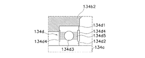
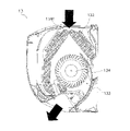
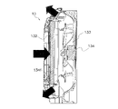
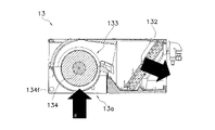
- FIG. 4 is a cross-sectional view of the fan motor 134; FIG. It is an enlarged view around the bearing 134d surrounded by the frame A. 4 is a flowchart showing a control flow of first control; 10 is a flowchart showing a control flow of first control executed by a fan motor control unit 123a according to modification 1A; FIG. 4 is a cross-sectional view showing air flow in a wall-mounted usage unit 13 using a cross-flow fan. FIG. 4 is a cross-sectional view showing the flow of air in a floor-mounted usage unit 13 using a turbofan. FIG. 4 is a cross-sectional view showing air flow in a ceiling-embedded usage unit 13 using a sirocco fan. FIG. 4 is a cross-sectional view showing air flow in a heat source unit 12 using a propeller fan;
- a blower device is used in, for example, a utilization unit of an air conditioner that utilizes a vapor compression refrigeration cycle, although the application is not limited.
- an air conditioner 1 using a blower 100 which is an example of the blower of the present disclosure, will be described with reference to the drawings.
- FIG. 1 is a schematic configuration diagram of an air conditioner 1 having an air blower 100 .
- the air conditioner 1 is a device that performs air conditioning operation (cooling operation and heating operation) of an air-conditioned space by performing a vapor compression refrigeration cycle.
- the air-conditioned space is, for example, a space within a building such as an office building, a commercial facility, or a residence.
- the air conditioner 1 mainly includes a heat source unit 12, a utilization unit 13, a liquid refrigerant communication pipe 14 and a gas refrigerant communication pipe 15, a control section 123, and a remote control 130, as shown in FIG.
- the air conditioner 1 has one usage unit 13, but the air conditioner 1 has a plurality of usage units 13 connected in parallel to the heat source unit 12 by refrigerant connecting pipes 14 and 15. may have Also, the air conditioner 1 may have a plurality of heat source units 12 . Also, the air conditioner 1 may be an integrated air conditioner in which the heat source unit 12 and the utilization unit 13 are integrally formed.
- the heat source unit 12 mainly includes an accumulator 17, a compressor 18, a flow direction switching mechanism 110, a heat source side heat exchanger 111, an expansion mechanism 112, a liquid side shutoff valve 113 and a gas side shutoff valve 114. , and a heat source side fan 115 .
- the usage unit 13 mainly has a usage side heat exchanger 132 and a usage side fan 133 .
- liquid refrigerant connecting pipe 14 and the gas refrigerant connecting pipe 15 are refrigerant connecting pipes that connect the heat source unit 12 and the utilization unit 13 .
- a refrigerant circuit 16 is configured by connecting the heat source unit 12 and the utilization unit 13 via the refrigerant communication pipes 14 and 15 .
- Control Unit 123 controls devices that constitute the heat source unit 12 and the utilization unit 13 to perform air conditioning operation.
- the control unit 123 has a fan motor control unit 123a.
- the fan motor control unit 123a rotationally drives the fan motor 134 and executes first control described later.
- the control unit 123 instructs the fan motor control unit 123a about a predetermined rotational speed range or a required rotational speed. Details of the fan motor control unit 123a and the first control will be described later.
- Control unit 123 is an example of a second control unit.
- a fan tap is set in the control unit 123 to change the rotation speed of the fan motor 134 in stages.
- the fan taps include an H tap that rotates the fan motor 134 in a high rotation speed range to generate a strong wind, an M tap that rotates the fan motor 134 in a medium rotation speed range to generate a weak wind, and Three levels of L taps are set to generate a breeze by rotating the fan motor 134 in the low rotation speed range.
- Each rpm range has an upper rpm limit and a lower rpm limit.
- the upper limit rotation speed and lower limit rotation speed of each rotation speed range are recorded in a storage device, which will be described later. Note that the number of fan taps is not limited to three stages as long as it is plural, and may be two stages or four stages or more.
- the control unit 123 is configured to be able to receive various signals transmitted from the remote controller 130 for the user to operate the air conditioner 1 .
- the various signals transmitted from the remote control include a signal for instructing start/stop of air conditioning operation, a signal for instructing air volume (fan tap), and a signal for various settings.
- the control unit 123 controls each device of the heat source unit 12 and the utilization unit 13 based on various signals transmitted from the remote controller 130 .
- a user can select a rotation speed range of the fan motor 134 by selecting a fan tap through the remote control 130 .
- the control unit 123 instructs the fan motor control unit 123a to select a rotation speed range preset according to the fan tap.
- the control unit 123 and the fan motor control unit 123a are realized by a computer.
- the control section 123 and the fan motor control section 123a include a control arithmetic device and a storage device (both not shown).
- a processor such as a CPU or a GPU, can be used for the control computing unit.
- the control arithmetic unit reads programs and various setting values stored in the storage device, and performs predetermined arithmetic processing according to the programs and various setting values. Furthermore, the control arithmetic unit can write the arithmetic result to the storage device and read the information stored in the storage device according to the program.
- control unit 123 (2-1-5) Operation of Air Conditioner Next, among the air conditioning operations executed by the control unit 123, the cooling operation and the heating operation will be described.
- the control unit 123 also performs a weak cooling/dehumidifying operation in which indoor air is dehumidified while performing relatively weak cooling, and a Known air conditioning operations such as reheat dehumidification operation in which dehumidification is performed without lowering the temperature of the target space by heating with a reheater, or thermo-off operation in which operation of the compressor 18 is stopped may be executed.
- the control unit 123 controls the operation of the flow direction switching mechanism 110 to change the state of the refrigerant circuit 16 so that the heat source side heat exchanger 111 is a refrigerant radiator (condenser). and the utilization side heat exchanger 132 switches to a state in which it functions as a refrigerant evaporator.
- the control unit 123 controls the operation of the flow direction switching mechanism 110 to connect the suction pipe 117 connected to the suction side of the compressor 18 between the flow direction switching mechanism 110 and the gas side shutoff valve 114 . It communicates with the second gas refrigerant pipe 121 .
- control unit 123 controls the operation of the flow direction switching mechanism 110 to connect the discharge pipe 118 connected to the discharge side of the compressor 18 to the flow direction switching mechanism 110 and the gas side of the heat source side heat exchanger 111. (See solid line in flow direction switching mechanism 110 in FIG. 1).
- the control unit 123 operates the compressor 18 , the heat source side fan 115 and the user side fan 133 .
- control unit 123 controls the rotation speed range or the required rotation speed of the compressor 18, the fan motor 115a of the heat source side fan 115, and the fan motor 134 of the user side fan 133 based on the measured values of various sensors.
- the opening of an electronic expansion valve which is an example of the expansion mechanism 112, is adjusted to a predetermined opening.
- the control unit 123 controls the operation of the various devices of the air conditioner 1
- the low-pressure gas refrigerant in the refrigeration cycle is sucked into the compressor 18, compressed to a high pressure in the refrigeration cycle, and then discharged from the compressor 18. be done.
- the high-pressure gas refrigerant discharged from the compressor 18 is sent to the heat source side heat exchanger 111 through the flow direction switching mechanism 110 .
- the high-pressure gas refrigerant sent to the heat source side heat exchanger 111 exchanges heat with air as a cooling source supplied by the heat source side fan 115 in the heat source side heat exchanger 111 functioning as a refrigerant radiator. It dissipates heat and becomes a high-pressure liquid refrigerant.
- the high-pressure liquid refrigerant that has released heat in the heat source side heat exchanger 111 is sent to the expansion mechanism 112 through the liquid refrigerant pipe 120 .
- the high-pressure liquid refrigerant is decompressed to become a low-pressure gas-liquid two-phase refrigerant.
- the low-pressure gas-liquid two-phase refrigerant decompressed by the expansion mechanism 112 is sent to the utilization side heat exchanger 132 through the liquid refrigerant pipe 120 , the liquid side shutoff valve 113 and the liquid refrigerant connecting pipe 14 .
- the low-pressure gas-liquid two-phase refrigerant sent to the user-side heat exchanger 132 is mixed with the air in the air-conditioned space supplied by the user-side fan 133 in the user-side heat exchanger 132 that functions as a refrigerant evaporator. It evaporates through heat exchange. At this time, the air cooled by exchanging heat with the refrigerant is supplied to the air-conditioned space, and the air-conditioned space is cooled.
- the low-pressure gas refrigerant evaporated in the utilization side heat exchanger 132 is sucked into the compressor 18 again through the gas refrigerant communication pipe 15 , the gas side shutoff valve 114 , the flow direction switching mechanism 110 and the accumulator 17 .
- the control unit 123 controls the operation of the flow direction switching mechanism 110 so that the heat source side heat exchanger 111 functions as a refrigerant evaporator and utilizes the state of the refrigerant circuit 16.
- the side heat exchanger 132 is switched to function as a refrigerant radiator (condenser).
- the control unit 123 controls the operation of the flow direction switching mechanism 110 so that the suction pipe 117 communicates with the first gas refrigerant pipe 119 and the discharge pipe 118 communicates with the second gas refrigerant pipe 121 (Fig. 1).
- the control unit 123 operates the compressor 18 , the heat source side fan 115 and the user side fan 133 .
- control unit 123 controls the rotation speed range or required rotation speed of the compressor 18, the fan motor 115a of the heat source side fan 115, and the fan motor 134 of the user side fan 133 based on the measured values of various sensors. , the opening of an electronic expansion valve, which is an example of the expansion mechanism 112, is adjusted to a predetermined opening.
- the control unit 123 controls the operation of various devices of the air conditioner 1 in this way, the low-pressure gas refrigerant in the refrigeration cycle is sucked into the compressor 18 and compressed to a high pressure in the refrigeration cycle, and then 18 is discharged.
- the high-pressure gas refrigerant discharged from the compressor 18 is sent to the utilization side heat exchanger 132 through the flow direction switching mechanism 110 , the gas side shutoff valve 114 and the gas refrigerant communication pipe 15 .
- the high-pressure gas refrigerant sent to the user-side heat exchanger 132 is combined with the air and heat in the air-conditioned space supplied by the user-side fan 133 in the user-side heat exchanger 132, which functions as a radiator (condenser) for the refrigerant.
- the heat is exchanged and the heat is released to become a high-pressure liquid refrigerant.
- the air heated by exchanging heat with the refrigerant is supplied to the air-conditioned space, and the air-conditioned space is heated.
- the high-pressure liquid refrigerant that has dissipated heat in the user-side heat exchanger 132 is sent to the expansion mechanism 112 through the liquid-refrigerant communication pipe 14 , the liquid-side shutoff valve 113 , and the liquid-refrigerant pipe 120 .
- the refrigerant sent to the expansion mechanism 112 is depressurized by the expansion mechanism 112 and becomes a low-pressure gas-liquid two-phase refrigerant.
- the low-pressure gas-liquid two-phase refrigerant decompressed by the expansion mechanism 112 is sent to the heat source side heat exchanger 111 through the liquid refrigerant pipe 120 .
- the low-pressure gas-liquid two-phase refrigerant sent to the heat source side heat exchanger 111 is mixed with air as a heat source supplied by the heat source side fan 115 in the heat source side heat exchanger 111 functioning as a refrigerant evaporator. After heat exchange, it evaporates and becomes a low-pressure gas refrigerant.
- the low-pressure refrigerant evaporated in the heat source side heat exchanger 111 is sucked into the compressor 18 again through the flow direction switching mechanism 110 and the accumulator 17 .
- the blower device 100 is composed of a user-side fan 133 and a fan motor controller 123a.
- the user-side fan 133 mainly has a fan motor 134 and a fan rotor 135 .
- FIG. 2 is a cross-sectional view of the fan motor 134. As shown in FIG.
- Fan Motor and Fan Rotor drives the fan rotor 135 to rotate.
- Fan motor 134 is an outer rotor type motor.
- the fan motor 134 is an inverter motor having a variable rotation speed and including an inverter (not shown).
- the number of revolutions of the fan motor 134 is controlled by the required number of revolutions of the control section 123 or the fan motor control section 123a.
- the fan motor 134 mainly has a stator 134a, a rotor 134b, a rotating shaft 134c, two bearings 134d, a casing 134e, and a temperature sensor 134f.
- Fan motor 134 is an example of a motor.
- the stator 134a is a substantially cylindrical member, and mainly has a cylindrical stator core 134a1 made of a magnetic material and a stator winding 134a2 wound around the stator core 134a1.
- Stator core 134a1 is arranged such that its central axis substantially coincides with the central axis of stator 134a.
- the central axis of the stator 134 a and the central axis of the stator core 134 a 1 are the rotation axis of the fan rotor 135 . Below, this central axis is referred to as the rotation axis O. As shown in FIG.
- a bolt hole 134a4 for fixing the casing 134e to the stator 134a with a bolt is formed on the outer periphery of the stator 134a.
- the stator 134 a is fixed to a casing (not shown) of the utilization unit 13 .
- Stator 134a has connector 134a3 for powering stator winding 134a2.
- the inverter of the fan motor 134 is connected to the controller 123 via a data line connected to the connector 134a3.
- the fan motor 134 receives control signals from the controller 123 or the fan motor controller 123a via the connector 134a3 and the data line.
- the rotor 134b is a cup-shaped member arranged with a predetermined gap on the outer peripheral side of the stator 134a.
- the rotor 134b mainly has a flat plate portion 134b1, an outer cylindrical portion 134b2, and a connecting portion 134b3.
- the flat plate portion 134b1 is mainly formed in a substantially disk shape.
- a circular opening 134b5 is formed in the center of the flat plate portion 28 for providing the connecting portion 134b3.
- the opening 134b5 is formed at a position where the center thereof intersects the rotation axis O at right angles.
- the outer cylindrical portion 134b2 is formed in a substantially cylindrical shape extending from the outer peripheral portion of the flat plate portion 134b1 along the rotation axis O toward the stator 134a.
- the outer cylindrical portion 134b2 has a magnetic pole member 134b4 that supplies field magnetic flux to the stator 134a.
- the magnetic pole member 134b4 faces the outer peripheral surface of the stator winding 134a2 via an air gap.
- the connecting portion 134b3 is a cylindrical member attached to the opening 134b5 of the flat plate portion 134b1.
- the outer peripheral surface of the connecting portion 134b3 is fixed to the inner peripheral surface of the opening 134b5 of the flat plate portion 134b1.
- a cylindrical rotating shaft 134c is fixed to the inner periphery of the connecting portion 134b3 so that the central axis thereof coincides with the rotating shaft center O. As shown in FIG.
- the bearing 134d holds the rotating shaft 134c rotatably with respect to the stator 134a.
- 3 is an enlarged view of the periphery of the bearing 134d surrounded by the frame A.
- FIG. The bearing 134d is a ball bearing having an outer ring 134d1, an inner ring 134d2 and balls 134d3.
- the outer peripheral surface of the outer ring 134d1 is fixed by fitting to the inner peripheral surface of the stator 134a, and the inner peripheral surface of the inner ring 134d2 is fixed by being fitted to the outer peripheral surface of the rotating shaft 134c.
- the bearing 134d is a sealed bearing filled with a lubricant 134d5 such as grease.
- a seal member 134d4 is attached to each end of the outer ring 134d1 and the inner ring 134d2 in the extending direction of the rotation axis O to seal a space in which the balls 134d3 are accommodated. is filled.
- the lubricant 134d5 is, but not limited to, urea-based or lithium soap-based grease, for example.
- two bearings 134d support the rotating shaft 134c.
- the two bearings 134d are arranged side by side on the inner periphery of the stator 134a with a predetermined gap in the extending direction of the rotation axis O. As shown in FIG.
- the casing 134e is a cup-shaped member that accommodates the rotor 134b together with the stator 134a.
- the casing 134e has a flat plate portion 134e1 and an outer cylindrical portion 134e2.
- the flat plate portion 134e1 is mainly formed in a substantially disc shape facing the flat plate portion 134b1 of the rotor 134b.
- An opening 134e3 for passing the rotating shaft 134c is formed in the center of the flat plate portion 134e1.
- the flat plate portion 134e1 faces the flat plate portion 134b1 of the rotor 134b with a predetermined gap therebetween.
- the outer cylindrical portion 134e2 is formed in a substantially cylindrical shape extending from the outer peripheral portion of the flat plate portion 134e1 along the rotation axis O toward the stator 134a.
- the outer cylinder portion 134e2 faces the outer cylinder portion 134b2 of the rotor 134b with a predetermined gap therebetween.
- the casing 134e has a bolt hole 134e4 at the end of the outer cylindrical portion 134b2 on the side of the stator 134a.
- the casing 134e is fixed to the stator by fastening bolts through the bolt holes 134e4 to the bolt holes 134a4 of the stator 134a.
- the temperature sensor 134f is a sensor for measuring the first temperature T1, which is the temperature of the bearing 134d.
- a well-known temperature sensor such as a thermistor, a thermocouple, or the like is used as the temperature sensor 134f, although not limited thereto.
- Temperature sensor 134f is attached to the outer surface of bearing 134d.
- the fan rotor 135 is fixed to the end of the rotating shaft 134c opposite to the stator 134a.
- the fan motor control section 123a rotationally drives the fan motor 134, acquires the first temperature T1 measured by the temperature sensor 134f, and executes the first control.
- the fan motor control unit 123a basically rotates the fan motor 134 in the rotation speed range or the required rotation speed instructed by the control unit 123 except when the first control is executed.
- the fan motor controller 123a is an example of a first controller.
- the first control is a control for suppressing the power consumption of the fan motor 134 and preventing the occurrence of poor oil film formation in the bearing 134d filled with lubricant.
- the fan motor control unit 123a reduces the rotation speed of the fan motor 134 when the first temperature T1, which is the temperature of the bearing 134d, drops in the operation of rotating the fan motor 134 in the low rotation speed range. More specifically, in the first control, the fan motor control unit 123a lowers the rotation speed of the fan motor 134 by lowering the lower limit rotation speed in the low rotation speed range.
- FIG. 4 is a flowchart showing the control flow of the first control.
- the control flow in FIG. 4 is started when the control unit 123 instructs the fan motor control unit 123a to rotate the fan motor 134 in the low rotation speed range (L tap).
- the reason why the control unit 123 instructs the fan motor control unit 123a to rotate the fan motor 134 in the low rotation speed range is not limited to when the user selects the L tap.
- the control unit 123 may instruct the fan motor control unit 123a to rotate the fan motor 134 in the low rotation speed range during weak cooling dehumidification operation, reheat dehumidification operation, thermo-off operation, or the like.
- step S100 the fan motor control unit 123a obtains the change in the first temperature T1 during the predetermined time ⁇ t1, and proceeds to step S110.
- step S110 when the fan motor control unit 123a determines that the first temperature T1 has decreased during the time ⁇ t1 and has become lower than the preset threshold temperature Tth (Yes), the process proceeds to step S120, and the threshold temperature Tth If it is determined that it is not lower than (No), the process proceeds to step S100.
- the threshold temperature Tth is, for example, 30° C. or higher and 38° C. or lower.
- step S120 the fan motor control unit 123a changes the lower limit of the low rotation speed range to the lower limit rotation speed Rmin1, which is lower than the preset lower limit rotation speed Rmin0, and proceeds to step S130.
- the lower limit rotation speed Rmin1 is also the rotation speed recorded in advance in the storage device of the control unit 123 .
- the lower limit rotation speed Rmin0 is, for example, 300 rpm or more and 500 rpm or less.
- the lower limit rotation speed Rmin1 is, for example, 100 rpm or more and 290 rpm or less.
- step S130 the fan motor control unit 123a acquires the change in the first temperature T1 during the predetermined time ⁇ t2, and proceeds to step S140.
- step S140 when the fan motor control unit 123a determines that the first temperature T1 has risen during the time ⁇ t2 and has become higher than the threshold temperature Tth (Yes), the process proceeds to step S150, where it becomes lower than the threshold temperature Tth. If not (No), the process proceeds to step S130.
- step S150 the fan motor control unit 123a resets the lower limit of the low rotation speed range to the lower limit rotation speed Rmin0, and proceeds to step S100.
- the blower device 100 includes a fan motor 134 with a variable rotational speed and a fan motor controller 123a.
- the fan motor 134 has a rotary shaft 134c supported by a bearing 134d filled with a lubricant 134d5.
- the fan motor control unit 123a drives the fan motor 134 to rotate.
- the fan motor control unit 123a executes the first control to reduce the rotation speed of the fan motor 134 when the first temperature T1, which is the temperature of the bearing 134d, drops during the operation of rotating the fan motor 134 in a predetermined low rotation speed range. do.
- the fan motor control unit 123a of the blower device 100 reduces the rotational speed of the fan motor 134 accordingly. Since the lubricating material enclosed in the bearing has the property that the lower the temperature, the higher the viscosity, the better the oil film is formed. Even if the rotational speed of 134 is reduced, the occurrence of poor oil film formation is suppressed.
- blower device 100 it is possible to suppress the power consumption of the fan motor 134 and prevent the occurrence of poor oil film formation in the bearing 134d filled with the lubricant 134d5.
- the fan motor control unit 123a lowers the rotation speed of the fan motor 134 by lowering the lower limit rotation speed in the low rotation speed range.
- the power consumption of the fan motor 134 is suppressed by a simple control of lowering the lower limit rotation speed in the low rotation speed range, while preventing the occurrence of poor oil film formation in the bearing 134d filled with the lubricant 134d5. can.
- the fan motor control unit 123a reduces the rotation speed of the fan motor 134 to the lower limit of the rotation speed range (fan tap) of the fan motor 134 that can be selected by the user.
- the fan motor control unit 123a can lower the rotation speed of the fan motor 134 below the lower limit rotation speed of the rotation speed range that can be selected by the user using the remote control 130. Therefore, power consumption of the fan motor 134 can be effectively suppressed.
- the blower device 100 includes a temperature sensor 134f that measures the first temperature T1.
- the temperature sensor is attached to 134e and bearing 134d.
- the first temperature T1 can be obtained by the temperature sensor 134f attached to the bearing 134d. Therefore, by accurately obtaining the temperature of the bearing 134d, it is possible to effectively reduce the rotation speed of the fan motor 134 and suppress the power consumption.
- the fan motor control unit 123a ensures that the amount of change in the first temperature T1 during the predetermined period D1 after the first temperature T1 drops below the threshold temperature Tth is within the predetermined temperature range ⁇ T. , the rotation speed of the fan motor 134 is reduced.
- FIG. 5 is a flowchart showing the control flow of the first control executed by the fan motor control section 123a according to Modification 1A.
- the main difference between the flowchart of FIG. 4 and the flowchart of FIG. 5 is that the flowchart shown in FIG. 5 has step S115. Differences will be mainly described below.
- step S110 when the fan motor control unit 123a determines that the first temperature T1 has decreased during the time ⁇ t1 and has become lower than the preset threshold temperature Tth (Yes), the process proceeds to step S115, and the threshold temperature Tth If it is determined that it is not lower than (No), the process proceeds to step S100.
- step S115 if the fan motor control unit 123a determines that the amount of change in the first temperature T1 during the period D1 after the first temperature T1 falls below the threshold temperature Tth is within the temperature range ⁇ T (Yes), step S120. If it is determined that the temperature is not within the temperature range ⁇ T (No), the process proceeds to step S100.
- the fan motor control unit 123a changes the lower limit value of the low rotational speed range after the first temperature T1 is lowered and stabilized within the temperature range ⁇ T. Therefore, the occurrence of the hunting phenomenon in which the rotational speed of the fan motor 134 repeats falling and rising is suppressed.
- the fan motor control unit 123a may prioritize the first control over the instruction of the required rotation speed from the control unit 123.
- the fan motor control unit 123a instructs the required rotation speed based on the measured values of various sensors and the like during the air-conditioning operation.
- the fan motor control unit 123a continues the first control and executes step S120 described above.
- the fan motor control unit 123a may control the reduction speed of the rotation speed of the fan motor 134 after changing the lower limit rotation speed Rmin0 to the lower limit rotation speed Rmin1 in step S120 of the first control.
- the speed of decrease in the rotational speed of the fan motor 134 in the first control is such that the temperature rise of the utilization-side heat exchanger 132 in the first control reaches the predetermined second temperature T2. It is set as follows. After changing the lower limit rotation speed Rmin0, the fan motor control unit 123a reduces the rotation speed of the fan motor 134 according to a preset reduction speed.
- the fan motor control unit 123a may reduce the speed of decreasing the rotation speed of the fan motor 134 stepwise after changing the lower limit rotation speed Rmin0 to the lower limit rotation speed Rmin1 in step S120 of the first control.
- the fan motor control section 123a may control the rate of increase in the rotational speed of the fan motor 134 after the first control is finished.
- the absolute value of the rate of increase in the rotation speed of the fan motor 134 after the end of the first control changes from the lower limit rotation speed Rmin0 to the lower limit rotation speed Rmin1 in step S120. It is set to be greater than the absolute value of the speed of decrease of the rotational speed of the fan motor 134 after the change.
- the rotation speed of the fan motor 134 is quickly increased, thereby preventing the occurrence of poor oil film formation in the bearing 134d due to operation in the low rotation speed range. can be prevented. Therefore, protection of the fan motor 134 can be prioritized over suppression of power consumption.
- the usage-side heat exchanger 132 is The passing air passes around the fan motor 134 .
- FIG. 6 is a cross-sectional view showing the flow of air in the wall-mounted utilization unit 13 using a cross-flow fan.
- FIG. 7 is a cross-sectional view showing the flow of air in the floor-mounted utilization unit 13 using a turbofan with arrows.
- a measuring temperature sensor 134f can be used to measure the first temperature T1.
- FIG. 8 is a cross-sectional view showing the flow of air in the ceiling-embedded usage unit 13 using a sirocco fan.
- a temperature sensor 134f can be used to measure the first temperature T1.
- a value obtained by adding a predetermined correction value to the measured temperature may be used as the first temperature T1.
- a value obtained by adding +2.5° C. to the measured temperature can be set as the first temperature T1.
- FIG. 9 is a cross-sectional view showing the flow of air in the heat source unit 12 using a propeller fan with arrows.
- the temperature of the heat source side heat exchanger 111 is measured because a large difference is unlikely to occur between the temperature of the air measured by the heat source side heat exchanger 111 and the temperature of the bearing of the fan motor 115a.
- a temperature sensor 134f can be used to measure the first temperature T1.
Landscapes
- Engineering & Computer Science (AREA)
- Mechanical Engineering (AREA)
- General Engineering & Computer Science (AREA)
- Chemical & Material Sciences (AREA)
- Combustion & Propulsion (AREA)
- Physics & Mathematics (AREA)
- Fluid Mechanics (AREA)
- Air Conditioning Control Device (AREA)
- Structures Of Non-Positive Displacement Pumps (AREA)
- Control Of Positive-Displacement Air Blowers (AREA)
- Air-Conditioning Room Units, And Self-Contained Units In General (AREA)
- Air-Conditioning For Vehicles (AREA)
Abstract
Description
(1)全体構成
本開示に係る送風装置は、用途を限定するものではないが、例えば、蒸気圧縮式の冷凍サイクルを利用する空気調和装置の利用ユニットに用いられる。ここでは、本開示の送風装置の一例である送風装置100が使用される空気調和装置1について、図面を参照しながら説明する。
(2-1)空気調和装置の構成
図1は、送風装置100を有する空気調和装置1の概略構成図である。
熱源ユニット12は、主として、アキュムレータ17、圧縮機18、流向切換機構110、熱源側熱交換器111、膨張機構112、液側閉鎖弁113及びガス側閉鎖弁114、及び熱源側ファン115を有している。
利用ユニット13は、利用側熱交換器132及び利用側ファン133を主に有する。
液冷媒連絡管14及びガス冷媒連絡管15は、熱源ユニット12と利用ユニット13とを接続する冷媒連絡管である。空気調和装置1では、熱源ユニット12と利用ユニット13とが冷媒連絡管14、15を介して接続されることで、冷媒回路16が構成される。
制御部123は、熱源ユニット12及び利用ユニット13を構成する機器を制御して、空調運転を実行する。
次に、制御部123が実行する空調運転のうち、冷房運転及び暖房運転について説明をする。なお、詳細な説明は省略するが、制御部123は、冷房運転及び暖房運転以外にも、比較的弱い冷房を行いながら室内空気の除湿を行う弱冷房除湿運転、空気を冷却して除湿しながら再熱器で加熱することにより対象空間の温度を下げずに除湿を行う再熱除湿運転、又は圧縮機18の運転を停止するサーモオフ運転等の周知の空調運転を実行可能であってもよい。
リモコン130を通じて冷房運転の開始が指示されると、制御部123は、流向切換機構110の動作を制御して、冷媒回路16の状態を熱源側熱交換器111が冷媒の放熱器(凝縮器)として機能し利用側熱交換器132が冷媒の蒸発器として機能する状態に切り換える。具体的には、制御部123は、流向切換機構110の動作を制御して、圧縮機18の吸入側に接続される吸入管117を、流向切換機構110とガス側閉鎖弁114とを接続する第2ガス冷媒管121と連通させる。また、制御部123は、流向切換機構110の動作を制御して、圧縮機18の吐出側に接続される吐出管118を、流向切換機構110と熱源側熱交換器111のガス側とを接続する第1ガス冷媒管119と連通させる(図1の流向切換機構110内の実線参照)。冷房運転時には、制御部123は、圧縮機18、熱源側ファン115及び利用側ファン133を運転する。また、冷房運転時には、制御部123は、各種センサの計測値等に基づき、圧縮機18、熱源側ファン115のファンモータ115a及び利用側ファン133のファンモータ134の回転数域又は要求回転数や、膨張機構112の一例である電子膨張弁の開度を所定開度に調節する。
リモコン130を通じて暖房運転の開始が指示されると、制御部123は、流向切換機構110の動作を制御して、冷媒回路16の状態を熱源側熱交換器111が冷媒の蒸発器として機能し利用側熱交換器132が冷媒の放熱器(凝縮器)として機能する状態に切り換える。具体的には、制御部123は、流向切換機構110の動作を制御して、吸入管117を第1ガス冷媒管119と連通させ、吐出管118を第2ガス冷媒管121と連通させる(図1の流向切換機構110内の破線参照)。暖房運転時には、制御部123は、圧縮機18、熱源側ファン115及び利用側ファン133を運転する。また、暖房運転時には、制御部123は、各種センサの計測値等に基づき、圧縮機18、熱源側ファン115のファンモータ115a及び利用側ファン133のファンモータ134の回転数域又は要求回転数や、膨張機構112の一例である電子膨張弁の開度を所定の開度に調節する。
送風装置100は、利用側ファン133と、ファンモータ制御部123aとにより構成される。利用側ファン133は、主に、ファンモータ134と、ファンロータ135とを有する。図2は、ファンモータ134の断面図である。
ファンモータ134は、ファンロータ135を回転駆動する。ファンモータ134は、アウタロータ型モータである。ファンモータ134は、インバータ(図示省略)を備えた回転数可変のインバータモータである。ファンモータ134は、制御部123又はファンモータ制御部123aの要求回転数により回転数が制御される。ファンモータ134は、主として、固定子134aと、回転子134bと、回転軸134cと、2つのベアリング134dと、ケーシング134eと、温度センサ134fとを有している。ファンモータ134は、モータの一例である。
ファンモータ制御部123aは、ファンモータ134を回転駆動するとともに、温度センサ134fの測定する第1温度T1を取得して、第1制御を実行する。ファンモータ制御部123aは、基本的に、第1制御の実行時以外では制御部123により指示された回転数域又は要求回転数でファンモータ134を回転駆動する。ファンモータ制御部123aは、第1制御部の一例である。
第1制御は、ファンモータ134の消費電力を抑制しながら、潤滑剤の封入されたベアリング134dにおける油膜形成不良の発生を防止するための制御である。ファンモータ制御部123aは、第1制御では、ファンモータ134を低回転数域で回転させる運転において、ベアリング134dの温度である第1温度T1が低下するとファンモータ134の回転数を低下させる。より具体的には、ファンモータ制御部123aは、第1制御において、低回転数域の下限回転数を低下させることによりファンモータ134の回転数を低下させる。
(4-1)
送風装置100は、回転数可変のファンモータ134と、ファンモータ制御部123aとを備える。ファンモータ134は、潤滑剤134d5の封入されたベアリング134dにより回転軸134cが支持される。ファンモータ制御部123aは、ファンモータ134を回転駆動する。ファンモータ制御部123aは、ファンモータ134を所定の低回転数域で回転させる運転において、ベアリング134dの温度である第1温度T1が低下するとファンモータ134の回転数を低下させる第1制御を実行する。
ファンモータ制御部123aは、第1制御において、低回転数域の下限回転数を低下させることによりファンモータ134の回転数を低下させる。
ファンモータ制御部123aは、第1制御において、ユーザーによって選択が可能なファンモータ134の回転数域(ファンタップ)の下限以下までファンモータ134の回転数を低下させる。
送風装置100は、第1温度T1を測定する温度センサ134fを備える。温度センサは134e、ベアリング134dに取り付けられている。
(5-1)変形例1A
図4に示した制御フローでは、ファンモータ制御部123aは、第1温度T1が低下して閾値温度Tthよりも低くなったと判断すると、低回転数域の下限を下限回転数Rmin1に変更したが、低回転数域の下限を変更するタイミングはこれに限定されない。
ファンモータ制御部123aは、第1制御を、制御部123からの要求回転数の指示に優先させてもよい。具体的には、ファンモータ制御部123aは、第1制御に際して、制御部123からの要求回転数の指示が下限回転数Rmin1未満である場合は、下限回転数Rmin1への変更を優先させる。
ファンモータ制御部123aは、第1制御のステップS120において下限回転数Rmin0を下限回転数Rmin1に変更した後にファンモータ134の回転数の低下速度を制御してもよい。
ファンモータ制御部123aは、第1制御が終了した後におけるファンモータ134の回転数の上昇速度を制御してもよい。
送風装置100では、温度センサ134fをベアリング134dに設けたが、温度センサ134fはベアリング134dの周囲の温度を第1温度T1として測定できる他の位置に設置されてもよい。
以上の説明では、利用側ファン133のファンモータ134が有するベアリング134dを第1制御の制御対象とする態様を説明したが、第1制御は、熱源ユニット12が有する熱源側ファン115のファンモータ115aを制御対象としてもよい。
12 熱源ユニット
13 利用ユニット(室内ユニット)
123 制御部(第2制御部)
123a ファンモータ制御部(第1制御部)
132 利用側熱交換器
133 利用側ファン
134 ファンモータ(モータ)
134c 回転軸
134d ベアリング
134d5 潤滑剤
134f 温度センサ
100 送風装置
T1 第1温度
T2 第2温度
D1 期間
ΔT 温度範囲
Claims (12)
- 潤滑剤(134d5)の封入されたベアリング(134d)により回転軸(134c)が支持された、回転数可変のモータ(134)と、
前記モータ(134)を回転駆動する第1制御部(123a)と
を備え、
前記第1制御部(123a)は、
前記モータ(134)を所定の低回転数域で回転させる運転において、前記ベアリング(134d)又は前記ベアリング(134d)の周囲の温度である第1温度(T1)が低下すると前記モータ(134)の回転数を低下させる第1制御を実行する、
送風装置(100)。 - 前記第1制御部(123a)は、
前記第1制御において、前記低回転数域の下限回転数を低下させることにより前記モータ(134)の回転数を低下させる、
請求項1に記載の送風装置(100)。 - 前記第1制御部は、
前記第1制御において、ユーザーによって選択が可能な前記モータ(134)の回転数の下限以下まで前記モータ(134)の回転数を低下させる、
請求項1又は2に記載の送風装置(100)。 - 前記第1制御部は、
前記第1制御において、前記第1温度(T1)が低下してから所定の期間(D1)、前記第1温度の変化量が所定の範囲(ΔT)内にある場合に、前記モータ(134)の回転数を低下させる、
請求項1から3のいずれかに記載の送風装置(100)。 - 前記第1温度(T1)を測定する温度センサ(134f)をさらに備え、
前記温度センサ(134f)は、
前記ベアリング(134d)に取り付けられている、
請求項1から4のいずれかに記載の送風装置(100)。 - 請求項1から5のいずれかに記載の送風装置(100)、前記第1温度(T1)を測定する温度センサ(134f)、及び熱交換器(132)を有する室内ユニット(13)と、
前記送風装置(100)を制御して前記室内ユニット(13)が設置された対象空間における空調運転を実行する第2制御部(123)と
を備える
空気調和装置(1)。 - 前記第2制御部(123)は、
前記第1制御部(123a)に前記モータ(134)の要求回転数を指示することにより前記送風装置(100)を制御し、
前記第1制御部(123a)は、
前記第1制御を、前記第2制御部(123)からの前記要求回転数の指示に優先させる、
請求項6に記載の空気調和装置(1)。 - 前記第1制御における前記モータ(134)の回転数の低下速度は、
前記第1制御における前記熱交換器(132)の上昇温度が所定の第2温度(T2)以下となるように設定される、
請求項6又は7に記載の空気調和装置(1)。 - 前記第1制御において前記モータ(134)の回転数は、
段階的に低下する、
請求項6から8のいずれかに記載の空気調和装置(1)。 - 前記第1制御の終了後における前記モータ(134)の回転数の上昇速度の絶対値が、
前記第1制御における前記低下速度の絶対値よりも大きい、
請求項8に記載の空気調和装置(1)。 - 前記温度センサ(134f)は、
前記熱交換器(132)に取り付けられている、
請求項6から10のいずれかに記載の空気調和装置(1)。 - 前記温度センサ(134f)は、
前記室内ユニット(13)の吸込口に取り付けられている、
請求項6から10のいずれかに記載の空気調和装置(1)。
Priority Applications (4)
| Application Number | Priority Date | Filing Date | Title |
|---|---|---|---|
| CN202280031116.4A CN117242304B (zh) | 2021-04-28 | 2022-04-27 | 送风装置和空调装置 |
| EP22795861.8A EP4332451B1 (en) | 2021-04-28 | 2022-04-27 | Blower and air conditioner |
| AU2022267164A AU2022267164B2 (en) | 2021-04-28 | 2022-04-27 | Blower and air conditioner |
| US18/384,478 US12066207B2 (en) | 2021-04-28 | 2023-10-27 | Blower and with controller controlling a motor |
Applications Claiming Priority (2)
| Application Number | Priority Date | Filing Date | Title |
|---|---|---|---|
| JP2021-076883 | 2021-04-28 | ||
| JP2021076883A JP7128428B1 (ja) | 2021-04-28 | 2021-04-28 | 送風装置及び空気調和装置 |
Related Child Applications (1)
| Application Number | Title | Priority Date | Filing Date |
|---|---|---|---|
| US18/384,478 Continuation US12066207B2 (en) | 2021-04-28 | 2023-10-27 | Blower and with controller controlling a motor |
Publications (1)
| Publication Number | Publication Date |
|---|---|
| WO2022230948A1 true WO2022230948A1 (ja) | 2022-11-03 |
Family
ID=83112425
Family Applications (1)
| Application Number | Title | Priority Date | Filing Date |
|---|---|---|---|
| PCT/JP2022/019131 Ceased WO2022230948A1 (ja) | 2021-04-28 | 2022-04-27 | 送風装置及び空気調和装置 |
Country Status (6)
| Country | Link |
|---|---|
| US (1) | US12066207B2 (ja) |
| EP (1) | EP4332451B1 (ja) |
| JP (1) | JP7128428B1 (ja) |
| CN (1) | CN117242304B (ja) |
| AU (1) | AU2022267164B2 (ja) |
| WO (1) | WO2022230948A1 (ja) |
Families Citing this family (1)
| Publication number | Priority date | Publication date | Assignee | Title |
|---|---|---|---|---|
| JP7643983B2 (ja) * | 2021-10-12 | 2025-03-11 | 株式会社Nttファシリティーズ | 空調装置 |
Citations (2)
| Publication number | Priority date | Publication date | Assignee | Title |
|---|---|---|---|---|
| KR20170002996A (ko) * | 2015-06-30 | 2017-01-09 | 주식회사 아모텍 | 공조장치용 인카센서 어셈블리 및 그 제어방법 |
| JP2017067046A (ja) | 2015-10-01 | 2017-04-06 | 三菱電機株式会社 | 送風機および空気調和機 |
Family Cites Families (17)
| Publication number | Priority date | Publication date | Assignee | Title |
|---|---|---|---|---|
| US5590539A (en) * | 1993-11-26 | 1997-01-07 | Omega Enterprises Inc. | Refrigeration apparatus and methods |
| JPH11294364A (ja) * | 1998-04-09 | 1999-10-26 | Hitachi Ltd | 軸受け油膜厚さ制御方法 |
| EP1837391B1 (en) * | 2004-12-17 | 2011-02-09 | NTN Corporation | Grease composition and grease-sealed roller bearing |
| FR2942656B1 (fr) * | 2009-02-27 | 2013-04-12 | Danfoss Commercial Compressors | Dispositif de separation de lubrifiant d'un melange lubrifiant-gaz frigorigene |
| CN102691875B (zh) * | 2011-03-22 | 2015-06-03 | 宝钢特钢有限公司 | 一种油膜轴承润滑油温度的调节方法 |
| JP5836859B2 (ja) * | 2012-03-19 | 2015-12-24 | 日立アプライアンス株式会社 | モータ制御装置、及びこれを用いたモータ駆動装置、圧縮機、冷凍装置、空気調和機、並びにモータ制御方法 |
| JP5924250B2 (ja) | 2012-11-30 | 2016-05-25 | 株式会社富士通ゼネラル | 空気調和機 |
| CN203743206U (zh) * | 2014-03-10 | 2014-07-30 | 太原科技大学 | 一种磁流体油膜轴承 |
| JP6225819B2 (ja) * | 2014-05-08 | 2017-11-08 | 三菱電機株式会社 | 空気調和機 |
| US11209006B2 (en) * | 2014-09-09 | 2021-12-28 | Twin City Fan Companies, Ltd. | Motor cooling device and method |
| JP6299549B2 (ja) * | 2014-09-29 | 2018-03-28 | トヨタ自動車株式会社 | 電池の冷却装置 |
| JP6079852B1 (ja) * | 2015-10-30 | 2017-02-15 | ダイキン工業株式会社 | 空気調和機 |
| CN109417329B (zh) * | 2016-07-04 | 2021-02-05 | 三菱电机株式会社 | 电动机以及空调装置 |
| JP6930246B2 (ja) * | 2017-06-27 | 2021-09-01 | 株式会社デンソー | 電子制御装置 |
| CN107799263A (zh) * | 2017-11-14 | 2018-03-13 | 太原科技大学 | 一种油膜轴承油基磁流体的制备方法 |
| US11867416B2 (en) * | 2019-11-13 | 2024-01-09 | Johnson Controls Tyco IP Holdings LLP | Remaining useful life estimator of components of HVAC system |
| CN112431764B (zh) * | 2020-12-02 | 2024-08-09 | 珠海格力电器股份有限公司 | 润滑效果好的压缩机结构及空调 |
-
2021
- 2021-04-28 JP JP2021076883A patent/JP7128428B1/ja active Active
-
2022
- 2022-04-27 AU AU2022267164A patent/AU2022267164B2/en active Active
- 2022-04-27 WO PCT/JP2022/019131 patent/WO2022230948A1/ja not_active Ceased
- 2022-04-27 EP EP22795861.8A patent/EP4332451B1/en active Active
- 2022-04-27 CN CN202280031116.4A patent/CN117242304B/zh active Active
-
2023
- 2023-10-27 US US18/384,478 patent/US12066207B2/en active Active
Patent Citations (2)
| Publication number | Priority date | Publication date | Assignee | Title |
|---|---|---|---|---|
| KR20170002996A (ko) * | 2015-06-30 | 2017-01-09 | 주식회사 아모텍 | 공조장치용 인카센서 어셈블리 및 그 제어방법 |
| JP2017067046A (ja) | 2015-10-01 | 2017-04-06 | 三菱電機株式会社 | 送風機および空気調和機 |
Non-Patent Citations (1)
| Title |
|---|
| See also references of EP4332451A4 |
Also Published As
| Publication number | Publication date |
|---|---|
| US20240053048A1 (en) | 2024-02-15 |
| JP7128428B1 (ja) | 2022-08-31 |
| EP4332451A4 (en) | 2024-10-02 |
| AU2022267164B2 (en) | 2025-05-22 |
| EP4332451A1 (en) | 2024-03-06 |
| CN117242304A (zh) | 2023-12-15 |
| JP2022170611A (ja) | 2022-11-10 |
| CN117242304B (zh) | 2024-04-19 |
| US12066207B2 (en) | 2024-08-20 |
| AU2022267164A1 (en) | 2023-12-07 |
| EP4332451B1 (en) | 2025-09-10 |
Similar Documents
| Publication | Publication Date | Title |
|---|---|---|
| CN102348945B (zh) | 用于运行冷凝器风扇的控制系统 | |
| JP3080558B2 (ja) | 寒冷地向けヒートポンプ空調機 | |
| CN111928454A (zh) | 空调器及其控制方法 | |
| US12072113B2 (en) | Fan device, and utilization unit and heat source unit of an air conditioner, hot water supplier, and air cleaner each including the fan device | |
| WO2016117113A1 (ja) | 空気調和機 | |
| US12066207B2 (en) | Blower and with controller controlling a motor | |
| JP2013253718A (ja) | 空気調和機の制御装置 | |
| WO2016125258A1 (ja) | 室内機及びこれを用いた空気調和装置 | |
| JP2004003721A (ja) | 空気調和機の運転制御方法 | |
| WO2023286181A1 (ja) | 空気調和装置 | |
| WO2021214930A1 (ja) | 空気調和システムおよび制御方法 | |
| JP3059900B2 (ja) | 空気調和機 | |
| JP2008215747A (ja) | 空気調和機 | |
| US20250216116A1 (en) | Compressor modulation in non-communicating mode | |
| JP2016188728A (ja) | 空気調和装置 | |
| JPH05256497A (ja) | 空気調和機のドライ運転制御方法 | |
| JP7227103B2 (ja) | 空気調和装置 | |
| KR100379271B1 (ko) | 냉난방에어컨의 운전제어방법 | |
| CA3247380A1 (en) | Compressor modulation in non-communicating mode | |
| JP4006390B2 (ja) | 空調装置 | |
| KR102194017B1 (ko) | 드레인 펌프를 구비하는 공기 조화기 | |
| JP2008089222A (ja) | ターボ冷凍機の制御方法 | |
| JP2019143949A (ja) | 空気調和機 | |
| JP2018059409A (ja) | 圧縮機および冷凍サイクル装置 | |
| JP5169003B2 (ja) | 空気調和装置 |
Legal Events
| Date | Code | Title | Description |
|---|---|---|---|
| 121 | Ep: the epo has been informed by wipo that ep was designated in this application |
Ref document number: 22795861 Country of ref document: EP Kind code of ref document: A1 |
|
| WWE | Wipo information: entry into national phase |
Ref document number: 202280031116.4 Country of ref document: CN |
|
| WWE | Wipo information: entry into national phase |
Ref document number: 202317077454 Country of ref document: IN |
|
| WWE | Wipo information: entry into national phase |
Ref document number: 2022267164 Country of ref document: AU Ref document number: AU2022267164 Country of ref document: AU |
|
| WWE | Wipo information: entry into national phase |
Ref document number: 2022795861 Country of ref document: EP |
|
| NENP | Non-entry into the national phase |
Ref country code: DE |
|
| ENP | Entry into the national phase |
Ref document number: 2022795861 Country of ref document: EP Effective date: 20231128 |
|
| ENP | Entry into the national phase |
Ref document number: 2022267164 Country of ref document: AU Date of ref document: 20220427 Kind code of ref document: A |
|
| WWG | Wipo information: grant in national office |
Ref document number: 2022795861 Country of ref document: EP |