WO2022234835A1 - ユーザ装置、基地局、及び通信制御方法 - Google Patents
ユーザ装置、基地局、及び通信制御方法 Download PDFInfo
- Publication number
- WO2022234835A1 WO2022234835A1 PCT/JP2022/019438 JP2022019438W WO2022234835A1 WO 2022234835 A1 WO2022234835 A1 WO 2022234835A1 JP 2022019438 W JP2022019438 W JP 2022019438W WO 2022234835 A1 WO2022234835 A1 WO 2022234835A1
- Authority
- WO
- WIPO (PCT)
- Prior art keywords
- sssg
- switching
- cell
- base station
- dci
- Prior art date
- Legal status (The legal status is an assumption and is not a legal conclusion. Google has not performed a legal analysis and makes no representation as to the accuracy of the status listed.)
- Ceased
Links
Images


Classifications
-
- H—ELECTRICITY
- H04—ELECTRIC COMMUNICATION TECHNIQUE
- H04W—WIRELESS COMMUNICATION NETWORKS
- H04W48/00—Access restriction; Network selection; Access point selection
- H04W48/08—Access restriction or access information delivery, e.g. discovery data delivery
- H04W48/12—Access restriction or access information delivery, e.g. discovery data delivery using downlink control channel
-
- H—ELECTRICITY
- H04—ELECTRIC COMMUNICATION TECHNIQUE
- H04L—TRANSMISSION OF DIGITAL INFORMATION, e.g. TELEGRAPHIC COMMUNICATION
- H04L5/00—Arrangements affording multiple use of the transmission path
- H04L5/0001—Arrangements for dividing the transmission path
- H04L5/0003—Two-dimensional division
- H04L5/0005—Time-frequency
- H04L5/0007—Time-frequency the frequencies being orthogonal, e.g. OFDM(A) or DMT
- H04L5/001—Time-frequency the frequencies being orthogonal, e.g. OFDM(A) or DMT the frequencies being arranged in component carriers
-
- H—ELECTRICITY
- H04—ELECTRIC COMMUNICATION TECHNIQUE
- H04L—TRANSMISSION OF DIGITAL INFORMATION, e.g. TELEGRAPHIC COMMUNICATION
- H04L5/00—Arrangements affording multiple use of the transmission path
- H04L5/003—Arrangements for allocating sub-channels of the transmission path
- H04L5/0053—Allocation of signalling, i.e. of overhead other than pilot signals
-
- H—ELECTRICITY
- H04—ELECTRIC COMMUNICATION TECHNIQUE
- H04L—TRANSMISSION OF DIGITAL INFORMATION, e.g. TELEGRAPHIC COMMUNICATION
- H04L5/00—Arrangements affording multiple use of the transmission path
- H04L5/0091—Signalling for the administration of the divided path, e.g. signalling of configuration information
- H04L5/0096—Indication of changes in allocation
-
- H—ELECTRICITY
- H04—ELECTRIC COMMUNICATION TECHNIQUE
- H04W—WIRELESS COMMUNICATION NETWORKS
- H04W36/00—Hand-off or reselection arrangements
- H04W36/0005—Control or signalling for completing the hand-off
- H04W36/0055—Transmission or use of information for re-establishing the radio link
- H04W36/0069—Transmission or use of information for re-establishing the radio link in case of dual connectivity, e.g. decoupled uplink/downlink
- H04W36/00692—Transmission or use of information for re-establishing the radio link in case of dual connectivity, e.g. decoupled uplink/downlink using simultaneous multiple data streams, e.g. cooperative multipoint [CoMP], carrier aggregation [CA] or multiple input multiple output [MIMO]
-
- H—ELECTRICITY
- H04—ELECTRIC COMMUNICATION TECHNIQUE
- H04W—WIRELESS COMMUNICATION NETWORKS
- H04W52/00—Power management, e.g. Transmission Power Control [TPC] or power classes
- H04W52/02—Power saving arrangements
- H04W52/0209—Power saving arrangements in terminal devices
- H04W52/0212—Power saving arrangements in terminal devices managed by the network, e.g. network or access point is leader and terminal is follower
- H04W52/0216—Power saving arrangements in terminal devices managed by the network, e.g. network or access point is leader and terminal is follower using a pre-established activity schedule, e.g. traffic indication frame
-
- H—ELECTRICITY
- H04—ELECTRIC COMMUNICATION TECHNIQUE
- H04W—WIRELESS COMMUNICATION NETWORKS
- H04W72/00—Local resource management
- H04W72/20—Control channels or signalling for resource management
- H04W72/23—Control channels or signalling for resource management in the downlink direction of a wireless link, i.e. towards a terminal
- H04W72/232—Control channels or signalling for resource management in the downlink direction of a wireless link, i.e. towards a terminal the control data signalling from the physical layer, e.g. DCI signalling
-
- Y—GENERAL TAGGING OF NEW TECHNOLOGICAL DEVELOPMENTS; GENERAL TAGGING OF CROSS-SECTIONAL TECHNOLOGIES SPANNING OVER SEVERAL SECTIONS OF THE IPC; TECHNICAL SUBJECTS COVERED BY FORMER USPC CROSS-REFERENCE ART COLLECTIONS [XRACs] AND DIGESTS
- Y02—TECHNOLOGIES OR APPLICATIONS FOR MITIGATION OR ADAPTATION AGAINST CLIMATE CHANGE
- Y02D—CLIMATE CHANGE MITIGATION TECHNOLOGIES IN INFORMATION AND COMMUNICATION TECHNOLOGIES [ICT], I.E. INFORMATION AND COMMUNICATION TECHNOLOGIES AIMING AT THE REDUCTION OF THEIR OWN ENERGY USE
- Y02D30/00—Reducing energy consumption in communication networks
- Y02D30/70—Reducing energy consumption in communication networks in wireless communication networks
Definitions
- the present disclosure relates to user equipment, base stations, and communication control methods used in mobile communication systems.
- Such techniques include a search space set group (SSSG) having a normal search space period and a power-saving SSSG with a longer search space period than the normal search space period or no search space.
- SSSG search space set group
- Techniques have been proposed in which an SSSG is set in a user equipment and a base station dynamically instructs the user equipment to switch to the SSSG (see Non-Patent Documents 1 to 3). Thereby, it is possible to reduce the power consumption of the user equipment while making it possible to apply the optimum SSSG according to the traffic state of the user equipment.
- cell group SSSG switching SSSG switching
- 3GPP contributions R1-2100170 "DCI-based power saving adaptation solutions”
- 3GPP contributions R1-2100593 "On enhancements to DCI-based UE power saving during DRX active time”
- 3GPP contribution R1-2101476 "DCI-based power saving adaptation during DRX Active Time”
- the number of cell groups set in the user equipment is not limited to one, and multiple cell groups can be set in the user equipment.
- the number of cell groups set in the user equipment is not limited to one, and multiple cell groups can be set in the user equipment.
- a user equipment in which a plurality of cell groups are set receives an SSSG switching instruction from a base station, it is not known which cell group the SSSG of the serving cell belonging to which cell group should be switched all at once. A problem was found that group SSSG switching could not be performed properly.
- an object of the present disclosure is to enable appropriate cell group SSSG switching.
- a user equipment is a user equipment in which a plurality of cell groups are set by a base station, and in a serving cell belonging to any one of the plurality of cell groups, a search space set group (SSSG) a communication unit that receives a switching instruction from the base station to instruct switching of the SSSG, based on a cell identifier or a cell group identifier included in the switching instruction, selects a target cell group as a switching target of the SSSG from the plurality of cell groups and a control unit that specifies (determines, selects) from The control unit simultaneously switches the SSSG for all serving cells in the identified target cell group in response to receiving the switching instruction.
- SSSG search space set group
- a base station is a base station that configures a plurality of cell groups for a user equipment, and in a serving cell belonging to one of the plurality of cell groups, a search space set group (SSSG).
- a communication unit configured to transmit a switching instruction instructing switching to the user device.
- the communication unit transmits the switching instruction including a cell group identifier of a target cell group to which the SSSG is switched among the plurality of cell groups or a cell identifier of a serving cell belonging to the target cell group.
- a communication control method is a communication control method executed by a user equipment in which a plurality of cell groups are set by a base station, and in a serving cell belonging to any one of the plurality of cell groups, A step of receiving a switching instruction for instructing switching of a search space set group (SSSG) from the base station, and a target cell group to be switched to the SSSG based on a cell identifier or a cell group identifier included in the switching instruction. from among the plurality of cell groups, and switching the SSSG for all serving cells in the target cell group identified from among the plurality of cell groups at once in response to receiving the switching instruction. step.
- SSSG search space set group
- FIG. 1 is a diagram showing the configuration of a mobile communication system according to an embodiment
- FIG. 2 is a diagram showing a configuration example of a protocol stack according to the embodiment
- FIG. 3 is a diagram for explaining search spaces and SSSG switching according to the embodiment
- FIG. 4 is a diagram for explaining search spaces and SSSG switching according to the embodiment
- FIG. 5 is a diagram for explaining search spaces and SSSG switching according to the embodiment
- FIG. 6 is a diagram showing the configuration of the UE according to the embodiment
- FIG. 7 is a diagram showing the configuration of a base station according to the embodiment
- FIG. 1 is a diagram showing the configuration of a mobile communication system according to an embodiment
- FIG. 2 is a diagram showing a configuration example of a protocol stack according to the embodiment
- FIG. 3 is a diagram for explaining search spaces and SSSG switching according to the embodiment
- FIG. 4 is a diagram for explaining search spaces and SSSG switching according to the embodiment
- FIG. 5 is a diagram for explaining search spaces and
- FIG. 8 is a diagram showing a first operation example of cell group SSSG switching according to the first embodiment
- FIG. 9 is a diagram showing a second operation example of cell group SSSG switching according to the first embodiment
- FIG. 10 is a diagram showing a configuration example of the SSSG switching MAC CE according to the first embodiment
- FIG. 11 is a diagram showing the operation according to the second embodiment
- FIG. 12 is a diagram showing the operation according to the second embodiment, focusing on the downlink
- FIG. 13 is a diagram showing the operation according to the second embodiment, focusing on the uplink
- FIG. 14 is a diagram showing the operation according to the third embodiment
- FIG. 15 is a diagram showing the operation according to the fourth embodiment, FIG.
- FIG. 16 is a diagram showing a first configuration example of information elements included in an RRC message according to the fourth embodiment
- FIG. 17 is a diagram showing a first configuration example of information elements included in an RRC message according to the fourth embodiment
- FIG. 18 is a diagram showing a second configuration example of information elements included in the RRC message according to the fourth embodiment
- FIG. 19 is a diagram showing a second configuration example of information elements included in the RRC message according to the fourth embodiment
- FIG. 20 is a diagram showing the operation according to the fifth embodiment
- FIG. 21 is a diagram showing a specific example 1 of the operation using the switching timer according to the fifth embodiment
- FIG. 22 is a diagram showing specific example 2 of the operation using the switching timer according to the fifth embodiment.
- the mobile communication system 1 is, for example, a system conforming to 3GPP Technical Specifications (TS).
- TS 3GPP Technical Specifications
- a mobile communication system based on the 3GPP standard 5th Generation System (5GS), that is, NR (New Radio) will be described as an example.
- the mobile communication system 1 has a network 10 and user equipment (UE) 100 communicating with the network 10 .
- the network 10 includes an NG-RAN (Next Generation Radio Access Network) 20, which is a 5G radio access network, and a 5GC (5G Core Network) 30, which is a 5G core network.
- NG-RAN Next Generation Radio Access Network
- 5G Core Network 5G Core Network
- the UE 100 is a device used by a user.
- the UE 100 is, for example, a portable device such as a mobile phone terminal such as a smart phone, a tablet terminal, a notebook PC, a communication module, or a communication card.
- the UE 100 may be a vehicle (eg, car, train, etc.) or a device provided therein.
- the UE 100 may be a transport body other than a vehicle (for example, a ship, an airplane, etc.) or a device provided thereon.
- the UE 100 may be a sensor or a device attached thereto.
- the UE 100 includes a mobile station, a mobile terminal, a mobile device, a mobile unit, a subscriber station, a subscriber terminal, a subscriber device, a subscriber unit, a wireless station, a wireless terminal, a wireless device, a wireless unit, a remote station, and a remote terminal. , remote device, or remote unit.
- NG-RAN 20 includes multiple base stations 200 .
- Each base station 200 manages at least one cell.
- a cell constitutes the minimum unit of a communication area.
- One cell belongs to one frequency (carrier frequency) and is composed of one component carrier.
- the term “cell” may represent a radio communication resource and may also represent a communication target of UE 100 .
- Each base station 200 can perform radio communication with the UE 100 residing in its own cell.
- the base station 200 communicates with the UE 100 using a RAN (Radio Access Network) protocol stack.
- Base station 200 provides NR user plane and control plane protocol termination towards UE 100 and is connected to 5GC 30 via NG interface.
- gNodeB gNodeB
- the 5GC 30 includes a core network device 300.
- the core network device 300 includes, for example, AMF (Access and Mobility Management Function) and/or UPF (User Plane Function).
- AMF Access and Mobility Management Function
- UPF User Plane Function
- AMF performs mobility management of UE100.
- UPF provides functions specialized for user plane processing.
- the AMF and UPF are connected with the base station 200 via the NG interface.
- the protocol of the radio section between the UE 100 and the base station 200 includes a physical (PHY) layer, a MAC (Medium Access Control) layer, an RLC (Radio Link Control) layer, a PDCP (Packet Data Convergence Protocol) layer, RRC layer.
- PHY physical
- MAC Medium Access Control
- RLC Radio Link Control
- PDCP Packet Data Convergence Protocol
- the PHY layer performs encoding/decoding, modulation/demodulation, antenna mapping/demapping, and resource mapping/demapping. Data and control information are transmitted between the PHY layer of the UE 100 and the PHY layer of the base station 200 via physical channels.
- the MAC layer performs data priority control, retransmission processing by hybrid ARQ (HARQ: Hybrid Automatic Repeat reQuest), random access procedures, and the like. Data and control information are transmitted between the MAC layer of the UE 100 and the MAC layer of the base station 200 via transport channels.
- the MAC layer of base station 200 includes a scheduler. The scheduler determines uplink and downlink transport formats (transport block size, modulation and coding scheme (MCS: Modulation and Coding Scheme)) and resources to be allocated to UE 100 .
- MCS modulation and coding scheme
- the RLC layer uses the functions of the MAC layer and PHY layer to transmit data to the RLC layer on the receiving side. Data and control information are transmitted between the RLC layer of the UE 100 and the RLC layer of the base station 200 via logical channels.
- the PDCP layer performs header compression/decompression and encryption/decryption.
- An SDAP (Service Data Adaptation Protocol) layer may be provided as an upper layer of the PDCP layer.
- the SDAP (Service Data Adaptation Protocol) layer performs mapping between an IP flow, which is the unit of QoS control performed by the core network, and a radio bearer, which is the unit of QoS control performed by the AS (Access Stratum).
- the RRC layer controls logical channels, transport channels and physical channels according to radio bearer establishment, re-establishment and release.
- RRC signaling for various settings is transmitted between the RRC layer of UE 100 and the RRC layer of base station 200 .
- UE 100 When there is an RRC connection between the RRC of UE 100 and the RRC of base station 200, UE 100 is in the RRC connected state. If there is no RRC connection between the RRC of the UE 100 and the RRC of the base station 200, the UE 100 is in RRC idle state. When the RRC connection between the RRC of UE 100 and the RRC of base station 200 is suspended, UE 100 is in RRC inactive state.
- the NAS layer located above the RRC layer performs session management and mobility management for UE100.
- NAS signaling is transmitted between the NAS layer of UE 100 and the NAS layer of mobility management device 221 .
- the UE 100 has an application layer and the like in addition to the radio interface protocol.
- FIG. A search space in this embodiment may be referred to as a search space set.
- the base station 200 configures the UE 100 with search spaces corresponding to candidate timings at which PDCCHs are arranged.
- UE 100 in the RRC connected state monitors PDCCH in the set search space and receives downlink control information (DCI) carried by PDCCH. Then, the UE 100 receives the physical downlink control channel (PDSCH) and/or transmits the physical uplink control channel (PUSCH) according to the resource allocation (scheduling) indicated by the DCI. For example, the UE 100 may monitor a set of PDCCH candidates according to the corresponding search space.
- DCI downlink control information
- PUSCH physical uplink control channel
- the UE 100 may monitor a set of PDCCH candidates according to the corresponding search space.
- UE 100 monitors a set of PDCCH candidates in a control resource set (CORESET) in a downlink BWP (DL BWP: Bandwidth Part) in a serving cell in which PDCCH monitoring is set according to the corresponding search space. good.
- monitoring may refer to decoding each of the PDCCH candidates according to the monitored DCI format.
- the base station 200 transmits an RRC message including PDCCH setting information (PDCCH setting information) to the UE 100, and performs various PDCCH settings for the UE 100.
- This RRC message is a UE-specific RRC message, and may be, for example, an RRC Reconfiguration message.
- the configuration information related to PDCCH includes a search space period (also referred to as a PDCCH monitoring period), a search space offset (also referred to as a PDCCH monitoring offset), a search space period (for example, the number of consecutive slots), symbols for PDCCH monitoring, and an aggregation level. , search space type, and DCI format.
- the search space type may include a UE-specific search space (USS: UE-specific search space) and/or a UE common search space (CSS: common search space).
- DCI formats include scheduling DCI formats used for PDSCH or PUSCH scheduling and non-scheduling DCI formats not used for such scheduling.
- DCI transmitted in a scheduling DCI format is called scheduling DCI
- DCI transmitted in a non-scheduling DCI format is called non-scheduling DCI.
- Scheduling DCI formats include a downlink DCI format used for PDSCH scheduling (eg, DCI format 1_0, DCI format 1_1, DCI format 1_2) and an uplink DCI format used for PUSCH scheduling (eg, DCI format 0_0, DCI format 0_1 and DCI format 0_2).
- non-scheduling DCI formats include, for example, DCI format 2_0 and DCI format 2_6.
- step S2 the UE 100 starts monitoring the PDCCH in the search space set by the base station 200.
- DCI format 1_0, DCI format 0_0, DCI format 1_1, DCI format 0_1, DCI format 1_2, and DCI format 0_2 are each set in the UE 100 .
- UE100 monitors PDCCH (DCI) based on the said setting.
- base station 200 may configure UE 100 to monitor DCI format 1_0 and DCI format 0_0 in a certain search space.
- base station 200 may configure UE 100 to monitor DCI format 1_1 and DCI format 0_1 in a certain search space.
- base station 200 may configure UE 100 to monitor DCI format 1_2 and DCI format 0_2 in a certain search space. That is, for example, base station 200 may configure UE 100 to monitor PDCCH candidates for DCI format 1_0 and DCI format 0_0 when CSS is configured for a certain search space. Also, base station 200 may configure UE 100 to monitor PDCCH candidates for DCI format 2_0 when CSS is configured for a certain search space. In addition, base station 200 instructs UE 100 to monitor PDCCH candidates for DCI format 1_0 and DCI format 0_0 or DCI format 1_1 and DCI format 0_1 when USS is configured for a certain search space.
- base station 200 instructs UE 100 to monitor PDCCH candidates for DCI format 1_0 and DCI format 0_0 or DCI format 1_2 and DCI format 0_2 when USS is configured for a certain search space. can be set to
- the UE 100 receives and detects DCI addressed to itself from the base station 200.
- the UE 100 receives C-RNTI (Cell-Radio Network Temporary Identifier) and MCS-C-RNTI (Modulation and Coding Scheme-C-RNTI) assigned to UE 100 from the base station 200, or CS-RNTI (Configured Scheduling- RNTI) is used to blind-decode the PDCCH, and the successfully decoded DCI is acquired as the DCI addressed to the own UE.
- the DCI transmitted from the base station 200 is added with CRC parity bits scrambled by C-RNTI and MCS-C-RNTI or CS-RNTI.
- step S4 the UE 100 receives downlink data from the base station 200 on the scheduled PDSCH.
- step S5 the UE 100 transmits uplink data to the base station 200 on the scheduled PUSCH.
- UE 100 monitors PDCCH in the search space set by base station 200.
- the base station 200 switches the search space setting applied by the UE 100 in order to reduce the power consumption of the UE 100 in the RRC connected state.
- each search space (each set of search spaces) may be associated with one CORESET.
- the search space setting may be set for each of one or more DL BWPs.
- base station 200 sets SSSG#0 having a normal search space cycle and SSSG#1 for power saving having a longer search space cycle than the normal search space cycle in UE 100.
- SSSG is a set (group) of search spaces, and may also be referred to as search space set (SSS) or search space group (SSG).
- SSS search space set
- SSG search space group
- an SSSG may be a set (group) of search spaces to which the same settings apply.
- FIG. 4 shows an example in which the base station 200 sets two SSSGs, SSSG#0 and SSSG#1, to the UE 100, but three The above SSSG may be set in the UE 100.
- an example of setting an SSSG having a long search space period as the power saving SSSG#1 is shown, but an SSSG having no search space may be set as the power saving SSSG#1.
- the UE 100 omits (skips) the monitoring of the PDCCH during the period of SSSG#1, so power consumption can be further reduced.
- "#0" in SSSG#0 and "#1" in SSSG#1 indicate an index (also called a search space group ID) for a set (group) of search spaces. That is, one or more search space sets may be associated with a set (group) of search spaces identified by an index.
- base station 200 may configure a set (group) of search spaces for UE 100 by configuring an index associated with the one or more search space sets.
- the name SSSG is merely an example, and any name may be used as long as it is a search space set (group) associated with one or more search space sets.
- search spaces may not exist in the set (group) of search spaces (search spaces may not be set). For example, when there is no search space, the UE 100 does not have to perform PDCCH monitoring (monitoring of PDCCH candidates). That is, when there is no search space, UE 100 may skip PDCCH monitoring.
- the base station 200 instructs the UE 100 to switch SSSG.
- Base station 200 uses a non-scheduling DCI (for example, DCI format 2_0) to instruct switching from SSSG#0 to SSSG#1.
- DCI format 2_0 for example, DCI format 2_0
- the scheduling DCI may be used as the SSSG switching instruction.
- UE 100 starts PDCCH monitoring in SSSG#1 with a symbol after a switch delay from the last symbol of PDCCH in SSSG#0.
- Such a switching delay time is set from the base station 200 to the UE 100 by higher layer signaling (ie, RRC message).
- Switching from SSSG#1 to SSSG#0 may be instructed by the base station 200 using DCI in the same way as switching from SSSG#0 to SSSG#1, or UE 100 may switch from SSSG#1 to SSSG# using a timer. May be switched to 0.
- a timer switching timer
- the UE 100 starts monitoring the PDCCH in the SSSG#1 in response to the detection of the switching instruction DCI to the SSSG#1, sets the value of the timer to the value set by the upper layer, and activates the timer.
- UE 100 decrements the value of the timer, stops monitoring PDCCH in SSSG#1 when the timer expires, and starts monitoring PDCCH in SSSG#0 after a switch delay.
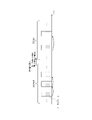
- FIG. 5 shows an example in which a serving cell #1 corresponding to component carrier #1 and a serving cell #2 corresponding to component carrier #2 are configured in UE 100.
- FIG. 5 it is efficient to perform SSSG switching in units of cell groups consisting of a plurality of cells instead of performing SSSG switching individually for each cell.
- the base station 200 transmits the SSSG switching DCI in the serving cell #1 to the UE 100, and the UE 100 simultaneously switches the SSSGs of the serving cells #1 and #2 from SSSG #0 to SSSG #1.
- Such a cell group is set from the base station 200 to the UE 100 through higher layer signaling (ie, RRC message).
- base station 200 may configure one primary cell and one or more secondary cells. That is, the serving cell includes primary cells and secondary cells.
- BWP Band Width Part
- the BWP may include a downlink BWP (DL BWP) and/or an uplink BWP (UL BWP). That is, up to four DL BWPs and/or up to four UL BWPs may be configured for one serving cell.
- DL BWP downlink BWP
- UL BWP uplink BWP
- control resource sets may be set in one DL BWP.
- the CORESET may include resources in the time domain and/or frequency domain configured for PDCCH monitoring.
- the CORESET may consist of a predetermined number of symbols (eg, 1 to 3 symbols) and a predetermined number of resource blocks (RBs) (eg, 6n (n ⁇ 1) RBs).
- cell group SSSG switching the number of cell groups configured in UE100 is not limited to one, and multiple cell groups may be configured in UE100.
- Cell Group #1 Serving Cells #1, #2, #3, #4 Cell Group #2: Serving Cells #5, #6, #7, #8 Cell Group #3: Serving Cells #9, #10, #11, #12 Cell Group #4: Serving Cells #13, #14, #15, #16
- PDCCH monitoring based on SSSG switching as described above is also referred to as a PDCCH monitoring procedure.
- UE 100 includes communication unit 110 and control unit 120 .
- the communication unit 110 performs wireless communication with the base station 200 by transmitting and receiving wireless signals to and from the base station 200 .
- the communication unit 110 has at least one receiver and at least one transmitter.
- Receivers and transmitters may comprise antennas and RF circuits.
- the antenna converts a signal into radio waves and radiates the radio waves into space. Also, the antenna receives radio waves in space and converts the radio waves into signals.
- the RF circuitry performs analog processing of signals transmitted and received through the antenna.
- the RF circuitry may include high frequency filters, amplifiers, modulators, low pass filters, and the like.
- the control unit 120 performs various controls in the UE 100.
- Control unit 120 controls communication with base station 200 via communication unit 110 .
- the operations of the UE 100 described above and below may be operations under the control of the control unit 120 .
- the control unit 120 may include at least one processor capable of executing a program and a memory that stores the program.
- the processor may execute a program to operate the control unit 120 .
- the control unit 120 may include a digital signal processor that performs digital processing of signals transmitted and received through the antenna and RF circuitry.
- the digital processing includes processing of the protocol stack of the RAN. Note that the memory stores programs executed by the processor, parameters related to the programs, and data related to the programs.
- the memory may include at least one of ROM (Read Only Memory), EPROM (Erasable Programmable Read Only Memory), EEPROM (Electrically Erasable Programmable Read Only Memory), RAM (Random Access Memory), and flash memory. All or part of the memory may be included within the processor.
- the communication unit 110 receives, from the base station 200, an SSSG switching instruction for instructing SSSG switching in a serving cell belonging to any one of a plurality of cell groups.
- the SSSG switching indication is an SSSG switching DCI that instructs SSSG switching.
- the control unit 120 identifies, from among a plurality of cell groups, the cell group to which the serving cell for which the SSSG switching instruction has been detected belongs, as the target cell group to which the SSSG switching is to be switched. Then, upon receiving the SSSG switching instruction, the control unit 120 simultaneously switches the SSSG for all serving cells in the identified target cell group.
- the control unit 120 uses the property that one serving cell can belong to only one cell group, and the cell group to which the serving cell in which the SSSG switching instruction is detected belongs is the SSSG switching target cell group. Identify. By this means, even when a plurality of cell groups are configured in the UE 100, the UE 100 can appropriately perform cell group SSSG switching.
- the communication unit 110 may receive from the base station 200 an SSSG switching instruction including a cell group identifier of the SSSG switching target cell group or a cell identifier of a cell included in the target cell group.
- an SSSG switch indication may be an SSSG switch medium access control (MAC) control element (CE).
- MAC medium access control
- CE control element
- the UE 100 can appropriately perform cell group SSSG switching.
- Base station 200 has communication unit 210 , network interface 220 , and control unit 230 .
- the communication unit 210 receives radio signals from the UE 100 and transmits radio signals to the UE 100.
- the communication unit 210 may comprise one or more receivers for receiving radio signals and one or more transmitters for transmitting radio signals.
- the network interface 220 transmits and receives signals to and from the network.
- the network interface 220 receives signals from adjacent base stations connected via an Xn interface, which is an interface between base stations, and transmits signals to adjacent base stations. Also, the network interface 220 receives signals from the core network device 300 connected via the NG interface, for example, and transmits signals to the core network device 300 .
- the control unit 230 performs various controls in the base station 200.
- the control unit 230 controls communication with the UE 100 via the communication unit 210, for example.
- the control unit 230 controls communication with nodes (for example, adjacent base stations, core network device 300) via the network interface 220, for example.
- the operations of the base station 200 described above and below may be operations under the control of the control unit 230 .
- the control unit 230 may include at least one processor capable of executing programs and a memory storing the programs.
- the processor may execute a program to operate the controller 230 .
- Control unit 230 may include a digital signal processor that performs digital processing of signals transmitted and received through the antenna and RF circuitry.
- the digital processing includes processing of the protocol stack of the RAN.
- the memory stores programs executed by the processor, parameters related to the programs, and data related to the programs. All or part of the memory may be included within the processor.
- the communication unit 210 transmits to the UE 100 an SSSG switching instruction for instructing switching of the SSSG in a serving cell belonging to any one of a plurality of cell groups set in the UE 100.
- the SSSG switching indication is an SSSG switching DCI that instructs SSSG switching.
- the communication unit 110 transmits an SSSG switching instruction to the UE 100 in the serving cell belonging to the SSSG switching target cell group.
- the target cell group is implicitly determined depending on which serving cell transmits the SSSG switching instruction.
- the communication unit 210 may transmit to the UE 100 an SSSG switching instruction including the cell group identifier of the SSSG switching target cell group or the cell identifier of the cell included in the target cell group.
- Such an SSSG switching instruction may be an SSSG switching MAC CE.
- the SSSG switching target cell group can be explicitly indicated by including the cell group identifier of the SSSG switching target cell group or the cell identifier of the cell included in the target cell group in the SSSG switching instruction. Therefore, the communication unit 210 may transmit an SSSG switching instruction to the UE 100 in a serving cell that does not belong to the SSSG switching target cell group.
- the SSSG switching instruction may be transmitted to the UE 100 at all times in the primary cell (PCell) among a plurality of serving cells.
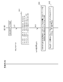
- the first operation example is an operation example in which the base station 200 implicitly indicates the SSSG switching target cell group to the UE 100 . It is assumed that the UE 100 is in the RRC connected state.
- the base station 200 transmits to the UE 100 an RRC message including cell group setting information regarding cell group setting together with the above-described PDCCH setting information.
- UE 100 receives the RRC message.
- This RRC message is a UE-specific RRC message, and may be, for example, an RRC Reconfiguration message.
- the cell group setting information may be configured as a cell list for each cell group. Each cell list may include the cell identifier of each serving cell belonging to the corresponding cell group.
- each cell group may be individually associated with PDCCH configuration information (including SSSG configuration information). That is, multiple SSSGs may be configured individually for each cell group.
- a default SSSG may be specified for each cell group. Details of the default SSSG will be described later in the fifth embodiment.
- step S12 the UE 100 (control unit 120) stores and applies the setting information included in the RRC message received in step S11, and controls communication with the base station 200 based on this setting information.
- the cell group set in the UE 100 is, for example, Cell Group #1: Serving Cells #1, #2, #3, #4 Cell Group #2: Serving Cells #5, #6, #7, #8 Cell Group #3: Serving Cells #9, #10, #11, #12 Cell group #4: Serving cells #13, #14, #15 and #16.
- the base station 200 determines the SSSG switching target cell group, and transmits the SSSG switching DCI to the UE 100 in the serving cell belonging to the target cell group.
- the UE 100 receives the SSSG switching DCI.
- UE 100 detects SSSG switching DCI by blind decoding of PDCCH.
- the SSSG switching DCI may be the scheduling DCI described above.
- the PDSCH or PUSCH scheduling can be notified to the UE 100 and the SSSG switching can be instructed to the UE 100, so efficient SSSG switching can be achieved.
- the SSSG switching DCI may be the non-scheduling DCI described above. As a result, the UE 100 can be instructed to switch to SSSG even when there is no data to be transmitted and received by the UE 100 .
- the non-scheduling DCI may be a DCI that can be transmitted to multiple UEs 100 at once.
- the non-scheduling DCI may be transmitted by applying an RNTI (Radio Network Temporary Identifier) common to multiple UEs 100 .
- RNTI Radio Network Temporary Identifier
- step S14 the UE 100 (control unit 120) identifies the cell group to which the serving cell in which the SSSG switching DCI was detected belongs as the SSSG switching target cell group. As a result, even if the identifier indicating the SSSG switching target cell group is not included in the SSSG switching DCI, the SSSG switching target cell group can be appropriately identified.
- UE 100 when SSSG switching DCI is received in serving cell #1, UE 100 (control unit 120) identifies cell group #1 to which serving cell #1 belongs as an SSSG switching target cell group.
- the UE 100 when the SSSG switching DCI is received by the serving cell #10, the UE 100 (control unit 120) identifies the cell group #3 to which the serving cell #10 belongs as the SSSG switching target cell group.
- step S15 the UE 100 (control unit 120) simultaneously switches the SSSG for all serving cells in the SSSG switching target cell group identified in step S14.
- UE 100 (control unit 120) collectively SSSG of all serving cells in the SSSG switching target cell group from the default SSSG (eg, SSSG # 0) to SSSG for power saving (eg, SSSG # 1) switch. That is, the UE 100 may determine the cell group to which the PDCCH monitoring procedure is applied based on the serving cell that detected the SSSG switching DCI. That is, when detecting SSSG switching DCI in a certain serving cell, UE 100 may apply the PDCCH monitoring procedure to the cell group to which the certain serving cell belongs.
- the UE 100 receives the cell group setting information used for setting one or more cell groups, and when detecting the SSSG switching DCI in a certain serving cell associated with (belonging to) a certain cell group, the SSSG switching DCI A PDCCH monitoring procedure may be applied to a cell group to which a serving cell that detects That is, the UE 100 receives the cell group setting information used for setting one or more cell groups, and in the case of detecting the SSSG switching DCI in a certain serving cell associated with (belonging to) a certain cell group, the SSSG switching DCI A PDCCH monitoring procedure may be applied to a cell group that detects . Here, UE 100 may apply the PDCCH monitoring procedure to all serving cells in the cell group.
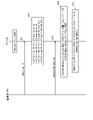
- the second operation example is an operation example in which the base station 200 explicitly indicates the SSSG switching target cell group to the UE 100 . It is assumed that the UE 100 is in the RRC connected state.
- steps S21 and S22 are the same as those of steps S11 and S12 described above.
- the base station 200 determines the SSSG switching target cell group, and the SSSG switching MAC CE containing the cell group identifier of the SSSG switching target cell group or the cell identifier of the serving cell belonging to the SSSG switching target cell group to the UE 100.
- the base station 200 may transmit the SSSG switching MAC CE to the UE 100 in a serving cell that does not belong to the SSSG switching target cell group.
- UE 100 receives the SSSG switching MAC CE.
- step S24 the UE 100 (control unit 120) identifies the SSSG switching target cell group from among a plurality of cell groups based on the cell identifier or cell group identifier included in the SSSG switching MAC CE.
- the UE 100 (control unit 120) identifies the cell group to which the serving cell indicated by the cell identifier included in the SSSG switching MAC CE belongs as the target cell group.
- UE 100 For example, if the cell identifier included in the SSSG switching MAC CE indicates serving cell #1, UE 100 (control unit 120) identifies cell group #1 to which serving cell #1 belongs as the SSSG switching target cell group. Alternatively, if the cell identifier included in the SSSG switching MAC CE indicates serving cell #10, UE 100 (control unit 120) identifies cell group #3 to which serving cell #10 belongs as the SSSG switching target cell group.
- step S25 the UE 100 (control unit 120) simultaneously switches the SSSG for all serving cells in the SSSG switching target cell group identified in step S24.
- UE 100 (control unit 120) collectively SSSG of all serving cells in the SSSG switching target cell group from the default SSSG (eg, SSSG # 0) to SSSG for power saving (eg, SSSG # 1) switch.
- the SSSG switching MAC CE may further include an SSSG identifier indicating the switching destination SSSG.
- the UE 100 (control unit 120) may simultaneously switch all serving cells in the SSSG switching target cell group identified in step S24 to the switching destination SSSG indicated by the SSSG identifier.
- the SSSG switching MAC CE may further include a BWP identifier indicating the bandwidth part (BWP) to which the SSSG switching target cell group belongs.
- the UE 100 (control unit 120) may identify the BWP of the SSSG switching target cell group identified in step S24 based on the BWP identifier.
- the SSSG switching MAC CE may be referred to as "Serving Cell Set based Search Space Set Group Indication MAC CE".
- the SSSG switching MAC CE may be configured to be identifiable by a MAC PDU subheader with an eLCID defined for the SSSG switching MAC CE.
- the SSSG switching MAC CE consists of the following fields and has a fixed size.
- This field indicates the ID of the serving cell to which MAC CE is applied, and the length of the field is, for example, 5 bits.
- this MAC CE is applied to all serving cells within the cell group to which the serving cell belongs.
- BWP ID (BWP identifier): This field indicates the downlink BWP to which this MAC CE is applied.
- the length of the BWP ID field is, for example, 2 bits.
- This field indicates the Search Space Set Group (SSSG) in which the UE monitors the PDCCH, ie the SSSG to switch to.
- the field length is, for example, 8 bits.
- At least part of the information included in the SSSG switching MAC CE in this second operation example may be included in the SSSG switching DCI in the above-described first operation example.
- the base station 200 implicitly indicates the SSSG switching target cell group to the UE 100 using the SSSG switching DCI.
- the base station 200 may implicitly indicate the SSSG switching target cell group to the UE 100 using the SSSG switching MAC CE. That is, the SSSG switching DCI in the above-described first operation example of cell group SSSG switching may be read as SSSG switching MAC CE.
- the UE 100 (control unit 120) may identify, as the target cell group, the cell group to which the serving cell in which the SSSG switching MAC CE is detected belongs.
- the SSSG switching MAC CE may include an SSSG identifier indicating the SSSG to switch to.
- the UE 100 (control unit 120) may simultaneously switch all serving cells in the SSSG switching target cell group to the switching destination SSSG indicated by the SSSG identifier.
- the SSSG switch MAC CE may further include a BWP identifier indicating the bandwidth portion (BWP) to which the target cell group belongs.
- the base station 200 may explicitly indicate the SSSG switching target cell group to the UE 100 using the SSSG switching DCI. That is, the cell group identifier of the SSSG switching target cell group or the cell identifier of the serving cell belonging to the SSSG switching target cell group may be included in the SSSG switching DCI.
- the SSSG switching DCI may be a scheduling DCI.
- the SSSG switching DCI may be a non-scheduling DCI.
- the scheduling DCI is used as the switching instruction DCI
- HARQ processing which is data retransmission processing by HARQ
- the UE 100 (control unit 120) suspends the start of switching instructed by the switching instruction DCI (scheduling DCI) while the retransmission-related timer associated with the HARQ process for the data scheduled by the switching instruction DCI (scheduling DCI) is in operation. do.
- the UE 100 receives scheduling DCI as a switching instruction DCI from the base station 200 on the PDCCH.
- a scheduling DCI may include an information field indicating a switching destination SSSG in addition to an information field indicating the PDSCH resource or PUSCH resource allocated to UE 100 .
- the UE 100 receives or transmits data scheduled by the scheduling DCI. For example, the UE 100 (communication unit 110) receives downlink data using the assigned PDSCH resources, and transmits uplink data using the assigned PUSCH resources.
- the UE 100 receives downlink data
- the UE 100 controls unit 120) attempts data decoding of the received downlink data, and HARQ feedback indicating whether data decoding is successful, that is, ACK Or NACK is fed back to the base station 200 .
- UE 100 (communication unit 110) transmits uplink data UE 100 (control unit 120) sends HARQ feedback indicating whether base station 200 has successfully decoded uplink data, that is, ACK or NACK. Receive from base station 200 .
- UE 100 (control unit 120) manages HARQ processing for each data to be received or transmitted using a timer, and continues HARQ processing until data decoding of the data is completed.
- step S53 the UE 100 (control unit 120) determines whether any of the next retransmission-related timers used for HARQ processing is in operation.
- Downlink HARQ RTT timer (drx-HARQ-RTT (Round Trip Time) - TimerDL) This timer is used for HARQ processing of downlink data, and defines the minimum period until downlink allocation for HARQ retransmission expected by the MAC entity of UE 100 .
- the UE 100 (control unit 120) activates the downlink HARQ RTT timer in response to transmission of HARQ feedback for downlink data.
- the UE 100 (control unit 120) does not need to monitor the PDCCH while the downlink HARQ RTT timer is operating.
- drx-RetransmissionTimerDL Downlink retransmission timer
- This timer is used for HARQ processing of downlink data and defines the maximum period until downlink retransmission is received.
- the UE 100 (control unit 120) activates the downlink retransmission timer.
- the UE 100 (control unit 120) monitors the PDCCH and waits for retransmission data while the downlink retransmission timer is operating.
- drx-HARQ-RTT-TimerUL This timer is used for HARQ processing of uplink data, and defines the minimum period until the MAC entity of UE 100 receives the HARQ retransmission grant.
- the UE 100 (control unit 120) activates the downlink retransmission timer according to transmission of uplink data.
- the UE 100 (control unit 120) does not need to monitor the PDCCH while the uplink HARQ RTT timer is operating.
- the UE 100 (control unit 120) activates the uplink retransmission timer when the uplink HARQ RTT timer expires.
- the UE 100 (control section 120) monitors the PDCCH while the uplink retransmission timer is operating.
- step S54 the UE 100 (control unit 120) suspends the start of switching indicated by the switching instruction DCI received in step S51. do.
- step S55 the UE 100 (control unit 120) initiates switching instructed by the switching instruction DCI received in step S51 or Run.
- the UE 100 may perform SSSG switching from the first slot after the retransmission-related timer expires.
- the period during which the retransmission-related timer is operating constitutes at least part of the switching delay time (Switch delay) for switching indicated by the switching instruction DCI.
- switch delay switching delay time
- UE 100 control section 120
- the start of switching instructed by the switching instruction DCI may be suspended.
- the switching delay time may include the period during which the following retransmission-related timers are in operation.
- the UE 100 when the UE 100 (control unit 120) is executing a plurality of HARQ processes, if even one retransmission-related timer of the plurality of HARQ processes is operating, switching instructed by the switching instruction DCI is started. may be retained. For example, the UE 100 is based on the expiration of drx-RetransmissionTimerDL corresponding to all HARQ processes and/or expiration of drx-RetransmissionTimerUL corresponding to all HARQ processes (for example, the first slot after expiration ) may perform SSSG switching.
- the UE 100 uses a configured DL assignment (that is, a downlink DCI format having a CRC scrambled with CS-RNTI) and/or a configured UL grant (that is, a CRC scrambled with CS-RNTI ) is received, the above actions may be performed.
- a configured DL assignment that is, a downlink DCI format having a CRC scrambled with CS-RNTI
- a configured UL grant that is, a CRC scrambled with CS-RNTI
- timers for DRX are used, but not limited to this, timers used for HARQ processing/retransmission processing for PDCCH skipping and/or SSSG switching set in higher layers may be used.
- Such timers are, for example, DCIbasedPowerSaving-HARQ-RTT-TimerDL, DCIbasedPowerSaving-HARQ-RTT-TimerUL, DCIbasedPowerSaving-RetransmissionTimerDL, DCIbasedPowerSaving-RetransmissionTimerUL, etc.
- DCIbasedPowerSaving-HARQ-RTT-TimerDL is an example of the downlink HARQ RTT timer.
- DCIbasedPowerSaving-HARQ-RTT-TimerUL is an example of an uplink HARQ RTT timer.
- DCIbasedPowerSaving-RetransmissionTimerDL is an example of a downlink retransmission timer.
- DCIbasedPowerSaving-RetransmissionTimerUL is an example of an uplink retransmission timer.
- step S101 the UE 100 (communication unit 110) receives the downlink scheduling DCI as the switching instruction DCI on the PDCCH.
- a downlink scheduling DCI is a DCI that allocates radio resources (that is, PDSCH resources) for downlink data.
- the UE 100 (communication unit 110) receives downlink data from the base station 200 using PDSCH resources allocated by the downlink scheduling DCI.
- UE 100 (control unit 120) attempts to decode the received downlink data.
- step S102 the UE 100 (communication unit 110) transmits to the base station 200 HARQ feedback indicating whether or not the downlink data received in step S102 has been successfully decoded.
- step S103 the UE 100 (control unit 120) activates the downlink HARQ RTT timer in response to transmission of HARQ feedback corresponding to downlink data.
- the UE 100 (control unit 120) suspends the start of switching indicated by the switching instruction DCI while the downlink HARQ RTT timer is operating.
- step S105 the UE 100 (control unit 120) determines whether the downlink data has been successfully decoded. If the downlink data has been successfully decoded (step S105: YES), in step S106, the UE 100 (control unit 120) starts switching instructed by the switching instruction DCI.
- step S107 the UE 100 (control unit 120) activates the downlink retransmission timer in response to the expiration of the downlink HARQ RTT timer. do.
- the UE 100 (control unit 120) monitors the PDCCH while the downlink retransmission timer is operating, and suspends the start of switching indicated by the switching instruction DCI.
- step S106 the UE 100 (control unit 120) starts switching instructed by the switching instruction DCI. If retransmission data is received from the base station 200 while the downlink retransmission timer is operating, the UE 100 (control unit 120) may stop the downlink retransmission timer and return to step S102.
- the UE 100 receives the uplink scheduling DCI as the switching instruction DCI on the PDCCH.
- the uplink scheduling DCI is a DCI that allocates radio resources (that is, PUSCH resources) for uplink data.
- step S202 the UE 100 (communication unit 110) transmits uplink data to the base station 200 using PUSCH resources allocated by the uplink scheduling DCI.
- step S203 the UE 100 (control unit 120) activates the uplink HARQ RTT timer in response to transmission of uplink data.
- the UE 100 (control unit 120) suspends the start of switching indicated by the switching instruction DCI while the uplink HARQ RTT timer is operating.
- step S204 When the uplink HARQ RTT timer expires (step S204: YES), the UE 100 (control unit 120) activates the uplink retransmission timer in step S205.
- the UE 100 (control unit 120) monitors the PDCCH while the uplink retransmission timer is operating, and suspends the start of switching indicated by the switching instruction DCI.
- step S207 the UE 100 (control unit 120) starts switching instructed by the switching instruction DCI.
- UE 100 that has received a scheduling DCI as a switching instruction starts switching while a retransmission-related timer associated with HARQ processing for data scheduled by the scheduling DCI is in operation. withhold.
- CSI reporting to the base station 200 may be considered.
- the UE 100 that has received the switching instruction DCI is instructed by the scheduling DCI to report the aperiodic CSI to the base station 200
- the UE 100 (control section 120) sends the CSI report to the base station 200 in the scheduled PUSCH.
- the start of switching indicated by the switching instruction DCI may be put on hold.
- the UE 100 (control unit 120) may start switching indicated by the switching instruction DCI in response to transmitting the CSI report on the scheduled PUSCH.
- the details of the CSI report will be explained in the third embodiment below.
- the period during which the UE 100 is in the power saving state is considered to be a period during which data transmission/reception is temporarily not performed, it is desirable to also reduce the power consumption required for SRS transmission, CSI measurement, and CSI reporting.
- SRS transmission refers to an operation in which the base station 200 transmits to the base station 200 an SRS, which is an uplink physical signal for channel estimation used for estimating the uplink channel state.
- SRS transmission is performed according to the setting of .
- SRS reporting is an operation for uplink link adaptation.
- Link adaptation adapts the modulation and coding scheme (MCS) applied to data transmission to channel conditions. During the period in which the UE 100 is in the power saving state, SRS transmission is suppressed because there is little need to perform uplink link adaptation.
- MCS modulation and coding scheme
- CSI measurement refers to the operation of measuring a reference signal used for estimating the downlink channel state, and the UE 100 performs CSI measurement according to the settings from the base station 200 .
- the UE 100 uses at least a channel state information reference signal (CSI-RS) and a synchronization signal/physical broadcast channel (SS/PBCH) block transmitted by the base station 200 CSI measurements based on one are made.
- CSI reporting refers to an operation of transmitting to base station 200 a CSI report indicating a channel state estimated according to the result of CSI measurement, and UE 100 reports CSI according to settings from base station 200 .
- CSI-RS channel state information reference signal
- SS/PBCH synchronization signal/physical broadcast channel
- the channel state includes a channel quality indicator (CQI), a rank indicator (RI), a precoding matrix indicator (PMI), an SS/PBCH block resource indicator (SS/PBCH block resource indicator: SSBRI), CSI-RS resource indicator (CSI-RS resource indicator: CRI), layer indicator (layer indicator: LI), and layer 1 reference signal received power (Layer 1 reference signal received power: L1-RSRP) including one or more of CSI reporting may be done on PUCCH or PUSCH.
- CSI measurement and CSI reporting are operations for downlink link adaptation. During the period in which the UE 100 is in the power saving state, the need to perform downlink link adaptation is low, so CSI measurement and CSI reporting are suppressed.
- step S301 UE 100 (control section 120) transmits SRS to base station 200, measures CSI, and reports CSI to base station 200 in the first state in which PDCCH is monitored in the search space.
- Predetermined control is performed to control the operation of at least one of In the first state, UE 100 (control unit 120) may periodically perform at least one of SRS transmission, CSI measurement, and CSI reporting.
- the UE 100 (control unit 120) performs at least one of periodic SRS transmission and periodic CSI reporting in the first state.
- Periodic SRS transmissions may include semi-persistent SRS transmissions.
- Periodic CSI reporting may include semi-persistent CSI reporting on PUCCH or PUSCH.
- the UE 100 receives, on the PDCCH, a switching instruction DCI that instructs switching to a second state (for example, power saving state) in which the search space settings are different from the first state.
- the switching instruction DCI is not limited to the scheduling DCI as described above, and may be a non-scheduling DCI.
- the switching indication DCI may include an information field indicating the switching destination SSSG.
- step S303 the UE 100 (control unit 120) performs control different from the predetermined control for at least one operation among SRS transmission, CSI measurement, and CSI reporting in response to receiving the switching instruction DCI.
- the UE 100 stops at least one of SRS transmission, CSI measurement, and CSI reporting within the switching delay time (Switch delay) from the first state to the second state.
- the UE 100 may stop periodic SRS transmission and periodic CSI reporting within the switching delay time.
- Such control is "within the switching delay time consisting of P switch symbols, the UE - Periodic SRS transmission and semi-persistent SRS transmission - Semi-persistent CSI configured on PUSCH Periodic CSI reporting that is L1-RSRP on PUCCH if ps-TransmitPeriodicL1-RSRP is not configured with value true L1 on PUCCH if ps-TransmitOtherPeriodicCSI is not configured with value true - not expected to perform periodic CSI reporting that is not RSRP'.
- the first state may be a state in which PDCCHs provided at predetermined intervals are monitored in search spaces
- the second state may be a state in which PDCCH monitoring is skipped (PDCCH skipping state).
- UE 100 does not have to perform at least one of SRS transmission, CSI measurement, and CSI reporting in the second state.
- the first state is a state of monitoring PDCCH in a search space provided in a predetermined cycle
- the second state is a state of monitoring PDCCH in a search space provided in a cycle longer than the predetermined cycle.
- Switching from the first state to the second state may be realized by SSSG switching.
- UE 100 (control section 120) may perform at least one operation of SRS transmission, CSI measurement, and CSI reporting only in the search space time interval.
- the UE 100 may perform aperiodic SRS transmission only in the monitor slot, which is the time interval of the search space.
- a control is such that "a UE for which SSSG switching is set by higher layer signaling triggers aperiodic SRS transmission when the search space period is longer than a predetermined value (e.g., 80 milliseconds). , do not expect SRS resources to be available outside of the corresponding monitor slot'.
- UE 100 may perform CSI measurement only in the monitor slot, which is the time interval of the search space.
- Such control is expressed as "a UE configured for SSSG switching by higher layer signaling excludes slots other than the monitor slot corresponding to the search space for the most recent CSI measurement occasions for CSI reporting".
- a UE for which SSSG switching is set by higher layer signaling if the period of the search space is longer than a predetermined value (for example, 80 ms), CSI-RS other than the corresponding monitor slot It may be phrased as "do not expect resources to be available”.
- the UE 100 that has received the switching instruction DCI performs switching instruction DCI for at least one operation among SRS transmission, CSI measurement, and CSI reporting in response to the reception of the switching instruction DCI. is different from the control before receiving the This makes it possible to apply control optimized for the power saving state, for example, control optimized for the extended search space period, in SRS transmission, CSI measurement, and CSI reporting. Further reduction in power consumption can be realized while reducing the power consumption.
- power saving is performed by switching SSSG.
- a plurality of SSSGs having different search space periods and from among various SSSGs including SSSGs having no search space, one or more SSSGs can be set in the UE 100, and switching of SSSGs is performed by DCI.
- Flexible power saving is realized by instructing with
- the base station 200 transmits one or more RRC messages to the UE100.
- the one or more RRC messages may include a dedicated RRC message (eg, RRCReconfiguration message) sent for each UE.
- UE 100 receives the RRC message.
- the RRC message is set in the index of each of one or more SSSGs set in the UE 100 and the information field in the switching instruction DCI that instructs switching of the SSSG applied by the UE 100 (hereinafter referred to as "SSSG information field"). It contains correspondence information that indicates the correspondence with the value to be specified.
- the one or more SSSGs include at least one of an SSSG that periodically monitors the PDCCH and an SSSG that skips the monitoring of the PDCCH.
- the correspondence information includes "SSSG index #0: value "00””, “SSSG index #1: value “01””, “SSSG index #2: value “10”. ””, and “SSSG index #3: value “11””.
- the base station 200 is not limited to collectively setting these four SSSGs in the UE 100 , and may set four SSSGs in the UE 100 by dividing the two SSSGs into two times, for example.
- the value set in the SSSG information field may be configured in bitmap format.
- bit position (code point) that is "1” may be associated with the SSSG index.
- the RRC message further includes search space configuration information associated with each SSSG index.
- Search space setting information includes one or more search space settings.
- Each search space configuration includes search space period, search space offset, search space duration (eg, number of consecutive slots), symbols for PDCCH monitoring, aggregation level, search space type, DCI format, and so on.
- the search space setting information associated with SSSG index #0 is information for setting the first search space cycle as the search space cycle.
- the search space setting information associated with SSSG index #1 is information for setting the second search space cycle as the search space cycle.
- the search space setting information associated with SSSG index #2 is information for setting the third search space cycle as the search space cycle.
- Search space setting information associated with SSSG index #4 is information indicating that no search space is set. That is, SSSG index #4 is associated with search space configuration information indicating PDCCH skipping.
- the RRC message may contain field setting information indicating the presence or absence of the SSSG information field for each of one or more DCI formats.
- the switching instruction DCI is a DCI having a DCI format in which the field setting information indicates that there is an SSSG information field.
- the presence or absence of the SSSG information field (presence/absence) may be set commonly or independently for the non-scheduling DCI and/or the scheduling DCI. Presence/absence of the SSSG information field may be set commonly for DCI format 1_1 and DCI format 0_1, and commonly for DCI format 1_2 and DCI format 0_2.
- the RRC message may contain bit number setting information indicating the number of bits in the SSSG information field for each of one or more DCI formats.
- the number of bits in the SSSG information field may be set directly for non-scheduling DCI and/or scheduling DCI, commonly or independently.
- the number of bits of the SSSG information field may be set commonly for DCI format 1_1 and DCI format 0_1 and/or commonly for DCI format 1_2 and DCI format 0_2. For example, even if up to 2-bit SSSG information field is set for DCI format 1_1 and/or DCI format 0_1 and/or 1-bit SSSG information field is set for DCI format 1_2 and DCI format 0_2, good.
- the RRC message may include a timer setting value of a switching timer for each of one or more SSSGs. Details of such a switching timer will be described in a fifth embodiment described later.
- step S402 the UE 100 (control unit 120) stores the information set by the base station 200.
- the base station 200 transmits to the UE 100 a MAC CE that designates activation or deactivation of SSSG for each SSSG index (hereinafter referred to as "SSSG state selection MAC CE"). good too.
- UE 100 receives the SSSG state selection MAC CE.
- the SSSG state selection MAC CE directs activation/deactivation for each SSSG index.
- the activated SSSG will be in a valid state as a switch-to SSSG, and the deactivated SSSG will be in an invalid state as a switch-to SSSG.
- deactivation may be prohibited for the default SSSG.
- the default SSSG will be explained in the fifth embodiment below.
- an SSSG state selection MAC CE is identified by a MAC subheader with an LCID defined for the SSSG state selection MAC CE.
- the SSSG state selection MAC CE may include a "cell ID field” indicating the serving cell to which the SSSG state selection MAC CE is applied.
- the SSSG state selection MAC CE may include a "Ti field” indicating activation/deactivation for each entry "i" of the SSSG index list consisting of SSSG indices.
- the 'Ti field' includes the 'T0 field' through the 'T(n-1) field' and is set to the value '1' for the SSSG to be activated.
- 'n' denotes the maximum number of SSSGs that can be activated, for example '4'.
- "T0 field” is set to "1” and " The "T1 field” is set to "0", the "T2 field” to "1", and the "T3 field” to "1".
- the SSSG information field may be configured in bitmap format intended only for activated SSSGs. For example, the first valid SSSG is mapped to codepoint 1 in the SSSG information field, the second valid SSSG is mapped to codepoint 2 in the SSSG information field. Assuming that SSSG index #0 is activated, SSSG index #1 is deactivated, SSSG index #2 is activated, and SSSG index #3 is deactivated, the number of bits in the SSSG information field is "2". Yes, "10" indicates SSSG index #0 and "01" indicates SSSG index #2.
- the base station 200 (communication unit 210) transmits a switching instruction DCI having an SSSG information field to the UE 100 on the PDCCH.
- UE 100 (communication section 110) receives the switching instruction DCI on the PDCCH.
- the UE 100 (control unit 120) may determine whether the DCI format of the detected DCI corresponds to the switching instruction DCI based on the field setting information set by the base station 200.
- step S405 the UE 100 (control unit 120) acquires the value set in the SSSG information field of the switching instruction DCI received in step S404.
- the UE 100 (control unit 120) may specify the number of bits in the SSSG information field based on the number-of-bits setting information set by the base station 200, and then acquire the value set in the SSSG information field.
- the UE 100 (control unit 120) identifies the number of bits in the SSSG information field based on the number of SSSG indexes set in the UE 100 (that is, the number of entries in the set SSSG index list), and the SSSG information field You can get the value set to .
- the UE 100 calculates the number of bits of the SSSG information field by an integer value rounded up after the decimal point of log 2 (I). and may be specified.
- step S406 the UE 100 (control unit 120), based on the correspondence information set from the base station 200, to the SSSG having the SSSG index corresponding to the value set in the SSSG information field in the received switching instruction DCI and monitor the PDCCH according to the SSSG of the switching destination. For example, in the example of FIG. 13, when the value set in the SSSG information field is "11", the UE 100 (control unit 120) determines that switching to SSSG of SSSG index #3 has been instructed, and the SSSG index Switch to #3 SSSG.
- the RRC message includes a PDCCH configuration (PDCCH-Config) information element.
- This information element is an information element used to configure UE specific PDCCH parameters such as control resource set (CORESET), search space and additional parameters for PDCCH acquisition.
- CORESET control resource set
- the PDCCH configuration (PDCCH-Config) information element can include an SSSG addition/modification list (searchSpaceSetToAddModList) and/or an SSSG release list (searchSpaceSetToReleaseList).
- the SSSG addition/change list is a list of SSSGs set in the UE 100 (SEQUENCE (SIZE (1..maxNrofSearchSpaceSets-r17)) OF SearchSpaceSet-r17).
- the SSSG release list is a list of SSSGs to be released in the UE 100 (SEQUENCE (SIZE (1.. maxNrofSearchSpaceSets-r17)) OF SearchSpaceSet-r17).
- “maxNrofSearchSpaceSets-r17” indicates the maximum number of SSSGs that can be set.
- searchSpaceSet-r17 which constitutes each entry of the SSSG addition/change list and the SSSG release list includes "SearchSpaceSetId-r17” which is the index of the SSSG and each search space setting included in this SSSG. and "seercSpaces-r17".
- searchSpaces-r17 is composed of a list of search space IDs (SEQUENCE (SIZE (0..maxNrofSearchSpaces-r17)) OF SearchSpaceId) of each search space setting included in this SSSG.
- the SSSG index 'SearchSpaceSetId-r17' has a number of bits of '0..maxNrofSearchSpaceSets-1-r17'.
- each search space setting indicates the SSSG to which the search space setting belongs.
- the PDCCH configuration (PDCCH-Config) information element can include a search space addition/change list (searchSpacesToAddModListExt2-r17).
- the search space addition/change list is a list consisting of 1 to 10 "SearchSpaceExt2-r17".
- the search space setting (SearchSpace) information element includes "searchSpaceSetIdList-r17" which is a list of SSSG indices associated with this search space setting.
- searchSpaceSetIdList-r17 is a list of SSSG indices associated with this search space setting.
- One search space setting can be associated with multiple SSSGs.
- UE 100 does not monitor PDCCH while using the SSSG for SSSG to which none of the search space settings configured in UE 100 is associated.
- the SSSG index of each of one or more SSSGs set in the UE 100 and the SSSG information field in the switching instruction DCI for instructing switching of the SSSG applied by the UE 100 It receives from the base station 200 the correspondence information indicating the correspondence with the value to be set.
- the one or more SSSGs include at least one of an SSSG that periodically monitors the PDCCH and an SSSG that skips the monitoring of the PDCCH. This enables flexible power saving with different SSSGs.
- one SSSG information field provided in the switching instruction DCI can specify one of a plurality of SSSGs with different search space cycles, or specify an SSSG that does not monitor the PDCCH. is used, it is possible to suppress an increase in the size of the DCI.
- a fifth embodiment will be described.
- the UE 100 switches between SSSGs on a timer basis, and three or more SSSGs can be configured in the UE 100 .
- the base station 200 may set one of the SSSGs set in the UE 100 as the default SSSG in the UE 100.
- the base station 200 may specify one of the SSSG indices set in the UE 100 as "defaultSSSG-Id".
- the default SSSG may be an SSSG determined by a predetermined rule shared in advance by the base station 200 and the UE 100 among SSSGs set in the UE 100 .
- the default SSSG may be the SSSG set in the UE 100 by the base station 200 as the default SSSG.
- step S501 the UE 100 (control unit 120) for which multiple SSSGs have been set by the base station 200 monitors the PDCCH using one of the multiple SSSGs.
- step S502 the UE 100 (communication unit 110) receives a switching instruction DCI that instructs switching to another SSSG from the base station 200 on the PDCCH.
- step S503 the UE 100 (control unit 120) switches to the SSSG specified by the switching instruction DCI, and activates the timer (switching timer) associated with the SSSG.
- step S504 the UE 100 (control unit 120) determines whether the switching timer has expired.
- step S505 the UE 100 (control unit 120) switches to the default SSSG among the multiple set SSSGs.
- the base station 200 can grasp the SSSG to which the UE 100 is switched. Since the switching timer is a value set by the base station 200, the base station 200 manages the switching timer in the same manner as the UE 100, and can recognize that the switching timer has expired in the UE 100.
- UE 100 (control unit 120), if the default SSSG is not set by the base station 200, specifically, if the default SSSG is not explicitly specified from the base station 200 as "defaultSSSG-Id", according to a predetermined rule Determine the default SSSG according to The predetermined rule is, for example, a rule defined by 3GPP technical specifications, and a rule shared in advance by the base station 200 and the UE 100 .
- the predetermined rule is the SSSG corresponding to the SSSG index with the smallest value among the SSSG indexes set in the UE 100, or the SSSG corresponding to the SSSG index with the largest value. good.
- the UE 100 determines the SSSG of SSSG index #0 as the default SSSG. If the rule is to set the SSSG corresponding to the SSSG index with the largest value as the default SSSG, the UE 100 (control unit 120) determines the SSSG of SSSG index #4 as the default SSSG.
- UE 100 receives from base station 200 the correspondence information indicating the correspondence between the SSSG index set in UE 100 and the value set in the SSSG information field in the switching instruction DCI.
- the predetermined rule may be a rule for determining, as the default SSSG, the SSSG corresponding to the SSSG index indicated by a specific value (eg, "0") set in the SSSG information field in the switching instruction DCI.
- the UE 100 determines, as the default SSSG, an SSSG having an SSSG index in which the value set in the SSSG information field in the switching instruction DCI is "0".
- the predetermined rule may be a rule that determines the SSSG corresponding to the SSSG index (for example, index #0) having a predetermined value among the SSSG indices set in the UE 100 as the default SSSG.
- the predetermined rule may be a rule for determining, among the SSSGs set in the UE 100, SSSGs other than SSSGs skipping PDCCH monitoring as default SSSGs. That is, UE 100 (control unit 120) may assume that the SSSG index corresponding to PDCCH skipping is not set as the default SSSG.
- the UE 100 may apply a specific SSSG when switching from the DRX reception off period to the reception on period (active time).
- the predetermined rule may be a rule that determines that particular SSSG as the default SSSG. That is, the UE 100 (control unit 120) may determine the first SSSG to monitor the PDCCH after the DRX reception off period has elapsed as the default SSSG.
- the UE 100 may receive a scheduling DCI indicating radio resources allocated to the UE 100 as a switching instruction DCI.
- UE 100 (control unit 120), after receiving the scheduling DCI as the switching instruction DCI, may start a switching timer at the timing of switching to one SSSG (specifically, the slot for performing SSSG switching). .
- the UE 100 (control unit 120) can suspend SSSG switching while the retransmission-related timer for HARQ processing is in operation. Therefore, when the scheduling DCI is received as the switching instruction DCI, the switching timer is started not at the timing at which the switching instruction DCI is received but at the timing at which the SSSG switching is executed.
- the UE 100 may use a common value as the switching timer value applied to two or more of the three or more SSSGs set in the UE 100.
- the base station 200 (control unit 230) may set a common value as the switching timer value applied to two or more of the three or more SSSGs set in the UE100.
- the UE 100 may use an individual value for each SSSG as the switching timer value applied to each SSSG set in the UE 100.
- the base station 200 (control unit 230) may set an individual switching timer setting value in the UE 100 for each SSSG.
- the UE 100 when the switching destination SSSG is an SSSG corresponding to PDCCH skipping, at the timing (slot) for starting switching to the SSSG, activates the switching timer associated with the SSSG. good too.
- the PDCCH skipping state that is, during a predetermined period during which PDCCH monitoring is skipped, resources used for PDCCH monitoring are not dedicated, and switching to the relevant SSSG can be started at any timing. Taking advantage of this advantage, it is possible to minimize the effect of the switching delay time without disturbing the PDCCH monitoring operation.
- the UE 100 may monitor the PDDCH assuming the default SSSG after the switching timer expires.
- the UE 100 is configured with a total of three SSSGs: Default SSSG, SSSG#x, and SSSG#y.
- the base station 200 the control unit 230 sets one common switching timer value in the UE 100 for SSSG#x and SSSG#y, which are not default SSSGs.
- UE 100 In period T11, UE 100 (control unit 120) monitors PDCCH using the default SSSG. UE 100 (communication section 110) receives a non-scheduling DCI instructing switching to SSSG#x in the last search space of period T11. UE 100 (control unit 120) starts a switching timer when receiving a non-scheduling DCI because HARQ processing does not occur in the case of non-scheduling DCI.
- UE 100 In period T12, UE 100 (control section 120) monitors PDCCH using SSSG#x while the switching timer is operating.
- SSSG#x is an SSSG with a longer search space period than the default SSSG.
- the switching timer expires, the UE 100 (control unit 120) switches to the default SSSG after the switching delay time (Switch delay) has elapsed.
- UE 100 In period T13, UE 100 (control unit 120) monitors PDCCH using the default SSSG. UE 100 (communication section 110) receives a scheduling DCI that instructs switching to SSSG#y in the last search space of period T13. Since HARQ processing occurs in the case of scheduling DCI, UE 100 (control unit 120) does not start the switching timer when scheduling DCI is received, and starts the switching timer at the timing (slot) at which switching to SSSG#y is executed. to start.
- the UE 100 (control unit 120) monitors the PDCCH using SSSG#y while the switching timer is operating.
- SSSG#y is an SSSG with a shorter search space period than the default SSSG.
- the switching timer expires, the UE 100 (control unit 120) switches to the default SSSG after the switching delay time (Switch delay) has elapsed.
- switch delay switching delay time
- UE 100 is configured with a total of three SSSGs: Default SSSG, SSSG#x for PDCCH skipping, and SSSG#y for PDCCH skipping.
- the base station 200 (control unit 230) sets individual switching timer values in the UE 100 for SSSG#x and SSSG#y, which are not default SSSGs.
- UE 100 In period T21, UE 100 (control unit 120) monitors PDCCH using the default SSSG.
- UE 100 (communication section 110) receives a non-scheduling DCI instructing switching to SSSG#x in the last search space of period T11.
- UE 100 (control unit 120) switches independently to SSSG#x at the timing (slot) at which switching to SSSG#x is performed because SSSG#x to be switched to is an SSSG that supports PDCCH skipping. Start the timer (Switching timer-1).
- UE 100 In period T22, UE 100 (control unit 120) skips PDCCH monitoring while Switching timer-1 is in operation. When the Switching timer-1 expires, the UE 100 (control unit 120) switches to the default SSSG after the Switch delay has elapsed.
- UE 100 In period T23, UE 100 (control unit 120) monitors PDCCH using the default SSSG.
- UE 100 (communication section 110) receives a scheduling DCI that instructs switching to SSSG#y in the last search space of period T23.
- UE 100 (control unit 120) performs switching set independently to SSSG#y at the timing (slot) at which switching to SSSG#y is performed because SSSG#x to which switching is to be switched is an SSSG that supports PDCCH skipping.
- Start the timer (Switching timer-2).
- the timer value of Switching timer-2 is greater than the timer value of Switching timer-1.
- UE 100 In period T24, UE 100 (control unit 120) skips PDCCH monitoring while Switching timer-2 is in operation. When the Switching timer-2 expires, the UE 100 (control unit 120) switches to the default SSSG after the Switch delay has elapsed. Then, in period T25, UE 100 (control section 120) monitors PDCCH using the default SSSG.
- the UE 100 switches the SSSG on a timer basis, even if three or more SSSGs can be set in the UE 100, by defining the default SSSG, The base station 200 can grasp the switching destination SSSG. Therefore, timer-based switching can be performed for various SSSGs.
- the base station 200 may include multiple units.
- the plurality of units may include a first unit hosting a higher layer included in the protocol stack and a second unit hosting a lower layer included in the protocol stack.
- the upper layers may include the RRC layer, the SDAP layer and the PDCP layer, and the lower layers may include the RLC layer, the MAC layer and the PHY layer.
- the first unit may be a CU (Central Unit) and the second unit may be a DU (Distributed Unit).
- the plurality of units may include a third unit that performs processing below the PHY layer.
- the second unit may perform processing above the PHY layer.
- the third unit may be an RU (Radio Unit).
- Base station 200 may be one of a plurality of units, and may be connected to other units of the plurality of units. Also, the base station 200 may be an IAB (Integrated Access and Backhaul) donor or an IAB node.
- IAB Integrated Access and Backhaul
- the mobile communication system 1 based on NR has been described as an example.
- the mobile communication system 1 is not limited to this example.
- the mobile communication system 1 may be a TS-compliant system of either LTE or another generation system (eg, 6th generation) of the 3GPP standard.
- Base station 200 may be an eNB that provides E-UTRA user plane and control plane protocol termination towards UE 100 in LTE.
- the mobile communication system 1 may be a system conforming to a TS of a standard other than the 3GPP standard.
- a mobile communication system to which carrier aggregation is applied has been described as an example.
- the mobile communication system is not limited to a mobile communication system that applies carrier aggregation, and may be a mobile communication system that applies dual connectivity.
- an example of operation using a primary cell (PCell) may be an operation using a special cell (SpCell).
- each operation flow described above is not limited to being implemented independently, but can be implemented by combining two or more operation flows. For example, some steps of one operation flow may be added to another operation flow, or some steps of one operation flow may be replaced with some steps of another operation flow.
- a program that causes a computer to execute each process performed by the UE 100 or the base station 200 may be provided.
- the program may be recorded on a computer readable medium.
- a computer readable medium allows the installation of the program on the computer.
- the computer-readable medium on which the program is recorded may be a non-transitory recording medium.
- the non-transitory recording medium is not particularly limited, but may be, for example, a recording medium such as CD-ROM or DVD-ROM.
- a circuit that executes each process performed by the UE 100 or the base station 200 is integrated, and at least a part of the UE 100 or the base station 200 is configured as a semiconductor integrated circuit (chipset, SoC (System-on-a-Chip)).
- “transmit” may mean performing at least one layer of processing in the protocol stack used for transmission, or physically transmitting the signal wirelessly or by wire. It may mean sending to Alternatively, “transmitting” may mean a combination of performing the at least one layer of processing and physically transmitting the signal wirelessly or by wire.
- “receive” may mean performing processing of at least one layer in the protocol stack used for reception, or physically receiving a signal wirelessly or by wire. may mean that Alternatively, “receiving” may mean a combination of performing the at least one layer of processing and physically receiving the signal wirelessly or by wire.
- “obtain/acquire” may mean obtaining information from among stored information.
- obtain/acquire may mean obtaining information among information received from other nodes. Also, “obtain/acquire” may mean obtaining information by generating the information.
- the terms “include” and “comprise” do not imply including only the listed items, but they may also include only the listed items. Also, the terms “include” and “comprise” mean that additional items in addition to the listed items may be included.
- “or” does not mean exclusive OR, but means logical OR.
- MAC medium access control
- CE control element
- the SSSG switching MAC CE includes the cell identifier of one serving cell included in the target cell group, The user apparatus (100) according to appendix 2, wherein the control unit (120) identifies, as the target cell group, a cell group to which the serving cell indicated by the cell identifier included in the SSSG switching MAC CE belongs.
- the SSSG switching MAC CE further includes an SSSG identifier indicating a switching destination SSSG, The user apparatus (100) according to appendix 2 or 3, wherein the control unit (120) simultaneously switches all serving cells in the target cell group to the switching destination SSSG indicated by the SSSG identifier.
- appendix 6 The user apparatus (100) according to appendix 1, wherein the switching instruction is SSSG switching downlink control information (DCI) that instructs switching of the SSSG.
- DCI downlink control information
- appendix 7 The user apparatus (100) according to appendix 6, wherein the SSSG switching DCI is a scheduling DCI used for scheduling a physical uplink control channel (PUSCH) or scheduling a physical downlink control channel (PDSCH).
- PUSCH physical uplink control channel
- PDSCH physical downlink control channel
- Appendix 8 The user apparatus (100) according to appendix 6, wherein the SSSG switching DCI is a non-scheduling DCI that is not used for scheduling a physical uplink control channel (PUSCH) or scheduling a physical downlink control channel (PDSCH).
- PUSCH physical uplink control channel
- PDSCH physical downlink control channel
- SSSG search space set group
Landscapes
- Engineering & Computer Science (AREA)
- Signal Processing (AREA)
- Computer Networks & Wireless Communication (AREA)
- Computer Security & Cryptography (AREA)
- Mobile Radio Communication Systems (AREA)
Abstract
Description
まず、図1を参照して、本実施形態に係る移動通信システム1の構成について説明する。移動通信システム1は、例えば、3GPPの技術仕様(Technical Specification:TS)に準拠したシステムである。以下において、移動通信システム1として、3GPP規格の第5世代システム(5th Generation System:5GS)、すなわち、NR(New Radio)に基づく移動通信システムを例に挙げて説明する。
次に、図3乃至図5を参照して、本実施形態に係るサーチスペース及びSSSG切り替えについて説明する。本実施形態においてサーチスペースは、サーチスペースセットと称されてもよい。
セルグループ#1:サービングセル#1,#2,#3,#4
セルグループ#2:サービングセル#5,#6,#7,#8
セルグループ#3:サービングセル#9,#10,#11,#12
セルグループ#4:サービングセル#13,#14,#15,#16
ここで、1つのサービングセルが属することができるセルグループは1つのみであるものとする。すなわち、1つのサービングセルが、1つのセルグループのみに属するように基地局200によって設定されてもよい。
次に、図6を参照して、本実施形態に係るUE100の構成について説明する。UE100は、通信部110及び制御部120を備える。
次に、図7を参照して、本実施形態に係る基地局200の構成について説明する。基地局200は、通信部210と、ネットワークインターフェイス220と、制御部230とを有する。
次に、図8を参照して、本実施形態に係るセルグループSSSG切り替えの第1動作例について説明する。第1動作例は、基地局200がSSSG切り替え対象セルグループをUE100に暗示的に示す動作例である。なお、UE100はRRCコネクティッド状態にあるものとする。
セルグループ#1:サービングセル#1,#2,#3,#4
セルグループ#2:サービングセル#5,#6,#7,#8
セルグループ#3:サービングセル#9,#10,#11,#12
セルグループ#4:サービングセル#13,#14,#15,#16である。
次に、図9を参照して、本実施形態に係るセルグループSSSG切り替えの第2動作例について、上述の第1動作例との相違点を主として説明する。第2動作例は、基地局200がSSSG切り替え対象セルグループをUE100に明示的に示す動作例である。なお、UE100はRRCコネクティッド状態にあるものとする。
上述のセルグループSSSG切り替えの第1動作例において、基地局200がSSSG切り替え対象セルグループをSSSG切り替えDCIによりUE100に暗示的に示す一例について説明した。しかしながら、基地局200は、SSSG切り替えDCIに代えて、SSSG切り替えMAC CEによりSSSG切り替え対象セルグループをUE100に暗示的に示してもよい。すなわち、上述のセルグループSSSG切り替えの第1動作例におけるSSSG切り替えDCIをSSSG切り替えMAC CEと読み替えてもよい。このような変更例において、UE100(制御部120)は、SSSG切り替えMAC CEが検出されたサービングセルが属するセルグループを対象セルグループとして特定してもよい。また、このような変更例において、SSSG切り替えMAC CEは、切り替え先のSSSGを示すSSSG識別子を含んでもよい。UE100(制御部120)は、SSSG切り替え対象セルグループ内のすべてのサービングセルについて、当該SSSG識別子が示す切り替え先のSSSGに一斉に切り替えてもよい。さらに、このような変更例において、SSSG切り替えMAC CEは、対象セルグループが属する帯域幅部分(BWP)を示すBWP識別子をさらに含んでもよい。
次に、図11を参照して、第2実施形態について説明する。第2実施形態において、SSSG切り替え指示としてSSSG切り替えDCIを用いることを想定し、特に、スケジューリングDCIを切り替え指示DCIとして用いることを主として想定する。
下りリンクデータのHARQ処理に用いるタイマであって、UE100のMACエンティティが予期するHARQ再送のための下りリンク割り当てまでの最小期間を規定するタイマである。UE100(制御部120)は、下りリンクデータに対するHARQフィードバックの送信に応じて下りリンクHARQ RTTタイマを起動する。UE100(制御部120)は、下りリンクHARQ RTTタイマの動作中は、PDCCHを監視する必要が無い。
下りリンクデータのHARQ処理に用いるタイマであって、下りリンク再送を受信するまでの最大期間を規定するタイマである。UE100(制御部120)は、下りリンクHARQ RTTタイマの満了時に、下りリンクデータ復号に成功していない場合、下りリンク再送タイマを起動する。UE100(制御部120)は、下りリンク再送タイマの動作中は、PDCCHを監視し、再送データを待ち受ける。
上りリンクデータのHARQ処理に用いるタイマであって、UE100のMACエンティティがHARQ再送許可(HARQ retransmission grant)を受信するまでの最小期間を規定するタイマである。UE100(制御部120)は、上りリンクデータの送信に応じて下りリンク再送タイマを起動する。UE100(制御部120)は、上りリンクHARQ RTTタイマの動作中は、PDCCHを監視する必要が無い。
上りリンクデータのHARQ処理に用いるタイマであって、上りリンク再送許可を受信するまでの最大期間を規定するタイマである。UE100(制御部120)は、上りリンクHARQ RTTタイマの満了時に上りリンク再送タイマを起動する。UE100(制御部120)は、上りリンク再送タイマの動作中はPDCCHを監視する。
・drx-HARQ-RTT-TimerDLの有効期限が切れた後の最初のシンボルの対応するHARQプロセスが正常に復号されなかった場合に開始されたdrx-RetransmissionTimerDLが動作中の期間:
・対応するPUSCH送信の最初の送信(バンドル内)が終了した後の最初のシンボルで対応するHARQプロセスに対して開始されたdrx-HARQ-RTT-TimerULが動作中の期間:
・drx-HARQ-RTT-TimerULの有効期限が切れた後の最初のシンボルで対応するHARQプロセスに対して開始されたdrx-RetransmissionTimerULが動作中の期間。
次に、図14を参照して、第3実施形態について説明する。
・周期的SRS送信及びセミパーシステントSRS送信
・PUSCHに設定されたセミパーシステントCSI
・ps-TransmitPeriodicL1-RSRPが値trueで構成されていない場合において、PUCCH上で行うL1-RSRPである周期的CSI報告
・ps-TransmitOtherPeriodicCSIが値trueで構成されていない場合において、PUCCH上で行うL1-RSRPではない周期的CSI報告を行うことを期待されない」と表現されてもよい。
次に、図15を参照して、第4実施形態について説明する。
次に、図20を参照して、第5実施形態について説明する。第5実施形態において、UE100がタイマベースでSSSGの切り替えを行う場合で、UE100に3つ以上のSSSGが設定され得る場合を想定する。
上述の実施形態において、基地局200は、複数のユニットを含んでもよい。複数のユニットは、プロトコルスタックに含まれる上位レイヤ(higher layer)をホストする第1のユニットと、プロトコルスタックに含まれる下位レイヤ(lower layer)をホストする第2のユニットとを含んでよい。上位レイヤは、RRCレイヤ、SDAPレイヤ及びPDCPレイヤを含んでよく、下位レイヤは、RLCレイヤ、MACレイヤ及びPHYレイヤを含んでよい。第1のユニットは、CU(Central Unit)であってよく、第2のユニットは、DU(Distributed Unit)であってよい。複数のユニットは、PHYレイヤの下位の処理を行う第3のユニットを含んでよい。第2のユニットは、PHYレイヤの上位の処理を行ってよい。第3のユニットは、RU(Radio Unit)であってよい。基地局200は、複数のユニットのうちの1つであってよく、複数のユニットのうちの他のユニットと接続されていてよい。また、基地局200は、IAB(Integrated Access and Backhaul)ドナー又はIABノードであってよい。
基地局(200)により複数のセルグループが設定されるユーザ装置(100)であって、
前記複数のセルグループのいずれかのセルグループに属するサービングセルにおいて、サーチスペースセットグループ(SSSG)の切り替えを指示する切り替え指示を前記基地局(200)から受信する通信部(110)と、
前記切り替え指示に含まれるセル識別子又はセルグループ識別子に基づいて、前記SSSGの切り替え対象とする対象セルグループを前記複数のセルグループの中から特定する制御部(120)と、を備え、
前記制御部(120)は、前記切り替え指示の受信に応じて、前記特定された対象セルグループ内のすべてのサービングセルについて前記SSSGを一斉に切り替える
ユーザ装置(100)。
前記切り替え指示は、前記SSSGの切り替えを指示するSSSG切り替え媒体アクセス制御(MAC)制御エレメント(CE)である
付記1に記載のユーザ装置(100)。
前記SSSG切り替えMAC CEは、前記対象セルグループに含まれる1つのサービングセルの前記セル識別子を含み、
前記制御部(120)は、前記SSSG切り替えMAC CEに含まれる前記セル識別子が示すサービングセルが属するセルグループを前記対象セルグループとして特定する
付記2に記載のユーザ装置(100)。
前記SSSG切り替えMAC CEは、切り替え先のSSSGを示すSSSG識別子をさらに含み、
前記制御部(120)は、前記対象セルグループ内のすべてのサービングセルについて、前記SSSG識別子が示す前記切り替え先のSSSGに一斉に切り替える
付記2又は3に記載のユーザ装置(100)。
前記SSSG切り替えMAC CEは、前記対象セルグループが属する帯域幅部分(BWP)を示すBWP識別子をさらに含む
付記2乃至4のいずれか1つに記載のユーザ装置(100)。
前記切り替え指示は、前記SSSGの切り替えを指示するSSSG切り替え下りリンク制御情報(DCI)である
付記1に記載のユーザ装置(100)。
前記SSSG切り替えDCIは、物理上りリンク制御チャネル(PUSCH)のスケジューリング又は物理下りリンク制御チャネル(PDSCH)のスケジューリングに用いるスケジューリングDCIである
付記6に記載のユーザ装置(100)。
前記SSSG切り替えDCIは、物理上りリンク制御チャネル(PUSCH)のスケジューリング又は物理下りリンク制御チャネル(PDSCH)のスケジューリングに用いない非スケジューリングDCIである
付記6に記載のユーザ装置(100)。
ユーザ装置(100)に複数のセルグループを設定する基地局(200)であって、
前記複数のセルグループのいずれかのセルグループに属するサービングセルにおいて、サーチスペースセットグループ(SSSG)の切り替えを指示する切り替え指示を前記ユーザ装置(100)に送信する通信部(210)を備え、
前記通信部(210)は、前記複数のセルグループのうち前記SSSGの切り替え対象とする対象セルグループのセルグループ識別子又は前記対象セルグループに属するサービングセルのセル識別子を含む前記切り替え指示を送信する
基地局(200)。
基地局(200)により複数のセルグループが設定されるユーザ装置(100)で実行する通信制御方法であって、
前記複数のセルグループのいずれかのセルグループに属するサービングセルにおいて、サーチスペースセットグループ(SSSG)の切り替えを指示する切り替え指示を前記基地局(200)から受信するステップと、
前記切り替え指示に含まれるセル識別子又はセルグループ識別子に基づいて、前記SSSGの切り替え対象とする対象セルグループを前記複数のセルグループの中から特定するステップと、
前記切り替え指示の受信に応じて、前記複数のセルグループの中から特定された前記対象セルグループ内のすべてのサービングセルについて前記SSSGを一斉に切り替えるステップと、を有する
通信制御方法。
Claims (10)
- 基地局(200)により複数のセルグループが設定されるユーザ装置(100)であって、
前記複数のセルグループのいずれかのセルグループに属するサービングセルにおいて、サーチスペースセットグループ(SSSG)の切り替えを指示する切り替え指示を前記基地局(200)から受信する通信部(110)と、
前記切り替え指示に含まれるセル識別子又はセルグループ識別子に基づいて、前記SSSGの切り替え対象とする対象セルグループを前記複数のセルグループの中から特定する制御部(120)と、を備え、
前記制御部(120)は、前記切り替え指示の受信に応じて、前記特定された対象セルグループ内のすべてのサービングセルについて前記SSSGを一斉に切り替える
ユーザ装置(100)。 - 前記切り替え指示は、前記SSSGの切り替えを指示するSSSG切り替え媒体アクセス制御(MAC)制御エレメント(CE)である
請求項1に記載のユーザ装置(100)。 - 前記SSSG切り替えMAC CEは、前記対象セルグループに含まれる1つのサービングセルの前記セル識別子を含み、
前記制御部(120)は、前記SSSG切り替えMAC CEに含まれる前記セル識別子が示すサービングセルが属するセルグループを前記対象セルグループとして特定する
請求項2に記載のユーザ装置(100)。 - 前記SSSG切り替えMAC CEは、切り替え先のSSSGを示すSSSG識別子をさらに含み、
前記制御部(120)は、前記対象セルグループ内のすべてのサービングセルについて、前記SSSG識別子が示す前記切り替え先のSSSGに一斉に切り替える
請求項2又は3に記載のユーザ装置(100)。 - 前記SSSG切り替えMAC CEは、前記対象セルグループが属する帯域幅部分(BWP)を示すBWP識別子をさらに含む
請求項2又は3に記載のユーザ装置(100)。 - 前記切り替え指示は、前記SSSGの切り替えを指示するSSSG切り替え下りリンク制御情報(DCI)である
請求項1に記載のユーザ装置(100)。 - 前記SSSG切り替えDCIは、物理上りリンク制御チャネル(PUSCH)のスケジューリング又は物理下りリンク制御チャネル(PDSCH)のスケジューリングに用いるスケジューリングDCIである
請求項6に記載のユーザ装置(100)。 - 前記SSSG切り替えDCIは、物理上りリンク制御チャネル(PUSCH)のスケジューリング又は物理下りリンク制御チャネル(PDSCH)のスケジューリングに用いない非スケジューリングDCIである
請求項6に記載のユーザ装置(100)。 - ユーザ装置(100)に複数のセルグループを設定する基地局(200)であって、
前記複数のセルグループのいずれかのセルグループに属するサービングセルにおいて、サーチスペースセットグループ(SSSG)の切り替えを指示する切り替え指示を前記ユーザ装置(100)に送信する通信部(210)を備え、
前記通信部(210)は、前記複数のセルグループのうち前記SSSGの切り替え対象とする対象セルグループのセルグループ識別子又は前記対象セルグループに属するサービングセルのセル識別子を含む前記切り替え指示を送信する
基地局(200)。 - 基地局(200)により複数のセルグループが設定されるユーザ装置(100)で実行する通信制御方法であって、
前記複数のセルグループのいずれかのセルグループに属するサービングセルにおいて、サーチスペースセットグループ(SSSG)の切り替えを指示する切り替え指示を前記基地局(200)から受信するステップと、
前記切り替え指示に含まれるセル識別子又はセルグループ識別子に基づいて、前記SSSGの切り替え対象とする対象セルグループを前記複数のセルグループの中から特定するステップと、
前記切り替え指示の受信に応じて、前記複数のセルグループの中から特定された前記対象セルグループ内のすべてのサービングセルについて前記SSSGを一斉に切り替えるステップと、を有する
通信制御方法。
Priority Applications (3)
| Application Number | Priority Date | Filing Date | Title |
|---|---|---|---|
| EP22798939.9A EP4336932A4 (en) | 2021-05-07 | 2022-04-28 | USER EQUIPMENT, BASE STATION AND COMMUNICATION CONTROL METHOD |
| CN202280033254.6A CN117337604A (zh) | 2021-05-07 | 2022-04-28 | 用户装置、基站以及通信控制方法 |
| US18/501,447 US20240107428A1 (en) | 2021-05-07 | 2023-11-03 | User equipment, base station, and communication control method |
Applications Claiming Priority (2)
| Application Number | Priority Date | Filing Date | Title |
|---|---|---|---|
| JP2021-079360 | 2021-05-07 | ||
| JP2021079360 | 2021-05-07 |
Related Child Applications (1)
| Application Number | Title | Priority Date | Filing Date |
|---|---|---|---|
| US18/501,447 Continuation US20240107428A1 (en) | 2021-05-07 | 2023-11-03 | User equipment, base station, and communication control method |
Publications (1)
| Publication Number | Publication Date |
|---|---|
| WO2022234835A1 true WO2022234835A1 (ja) | 2022-11-10 |
Family
ID=83932757
Family Applications (1)
| Application Number | Title | Priority Date | Filing Date |
|---|---|---|---|
| PCT/JP2022/019438 Ceased WO2022234835A1 (ja) | 2021-05-07 | 2022-04-28 | ユーザ装置、基地局、及び通信制御方法 |
Country Status (4)
| Country | Link |
|---|---|
| US (1) | US20240107428A1 (ja) |
| EP (1) | EP4336932A4 (ja) |
| CN (1) | CN117337604A (ja) |
| WO (1) | WO2022234835A1 (ja) |
Families Citing this family (3)
| Publication number | Priority date | Publication date | Assignee | Title |
|---|---|---|---|---|
| EP4336930A4 (en) * | 2021-05-07 | 2024-11-13 | Denso Corporation | COMMUNICATION DEVICE, BASE STATION AND COMMUNICATION METHOD |
| US12501427B2 (en) * | 2023-04-19 | 2025-12-16 | Qualcomm Incorporated | Uplink transmission handling after a bandwidth part switch for dynamic uplink skipping |
| US20250330798A1 (en) * | 2024-04-23 | 2025-10-23 | Qualcomm Incorporated | Dynamic resource allocation based on network configuration |
Citations (3)
| Publication number | Priority date | Publication date | Assignee | Title |
|---|---|---|---|---|
| WO2020102146A2 (en) * | 2018-11-13 | 2020-05-22 | Intel Corporation | User equipment power saving in new radio system |
| US20210045147A1 (en) * | 2019-08-05 | 2021-02-11 | Hua Zhou | Cross Carrier Scheduling |
| JP2021079360A (ja) | 2019-11-22 | 2021-05-27 | 大川原化工機株式会社 | 噴霧熱分解装置及び噴霧熱分解方法 |
Family Cites Families (22)
| Publication number | Priority date | Publication date | Assignee | Title |
|---|---|---|---|---|
| US9641301B2 (en) * | 2013-03-27 | 2017-05-02 | Sharp Kabushiki Kaisha | Terminal device, base station device, communication method, and integrated circuit |
| JP2019204983A (ja) * | 2016-09-21 | 2019-11-28 | シャープ株式会社 | 端末装置、通信方法、および、集積回路 |
| US10448414B2 (en) * | 2017-03-23 | 2019-10-15 | Sharp Kabushiki Kaisha | Downlink control channel for uplink ultra-reliable and low-latency communications |
| WO2019099533A1 (en) * | 2017-11-16 | 2019-05-23 | Sharp Laboratories Of America, Inc. | User equipments, base stations and methods |
| CN110831217B (zh) * | 2018-08-10 | 2021-12-14 | 华为技术有限公司 | 一种数据调度方法及装置 |
| WO2020065624A1 (en) * | 2018-09-28 | 2020-04-02 | Telefonaktiebolaget Lm Ericsson (Publ) | Transitioning between different scheduling delay assumptions |
| US11330577B2 (en) * | 2019-01-08 | 2022-05-10 | Qualcomm Incorporated | Search space activation for channel monitoring |
| US12082244B2 (en) * | 2019-03-28 | 2024-09-03 | Qualcomm Incorporated | Dynamic physical downlink control channel (PDCCH) monitoring mode switching, configuration, and control |
| WO2020246858A1 (en) * | 2019-06-06 | 2020-12-10 | Samsung Electronics Co., Ltd. | Method and apparatus for determining of a search space set for physical downlink control channel (pdcch) monitoring |
| WO2021048581A1 (en) * | 2019-09-09 | 2021-03-18 | Orope France Sarl | A method for control channel detection in wideband operation |
| US11690087B2 (en) * | 2019-10-30 | 2023-06-27 | Qualcomm Incorporated | Control resource set and search space set configuration for full duplex operation |
| KR102927508B1 (ko) * | 2019-11-08 | 2026-02-12 | 텔레폰악티에볼라겟엘엠에릭슨(펍) | 탐색 공간 세트 그룹의 제어 채널 모니터링을 스위칭하는 방법 |
| CN113162726B (zh) * | 2020-01-23 | 2023-03-21 | 维沃移动通信有限公司 | Pdcch的检测方法及终端 |
| CN116114334B (zh) * | 2020-08-07 | 2025-09-23 | 中兴通讯股份有限公司 | 功率节省技术 |
| CN114124293A (zh) * | 2020-08-31 | 2022-03-01 | 维沃移动通信有限公司 | 物理下行控制信道的监听方法、装置和设备 |
| TWI832107B (zh) * | 2020-10-22 | 2024-02-11 | 香港商鴻穎創新有限公司 | 下一代網路中的搜索空間群組切換 |
| JP2024513697A (ja) * | 2021-03-31 | 2024-03-27 | インテル コーポレイション | 探索空間セットグループ(sssg)の物理ダウンリンク制御チャネル(pdcch)モニタリング設定間の切替 |
| US12309797B2 (en) * | 2021-04-05 | 2025-05-20 | Ofinno, Llc | Requesting feedback information in multi-downlink scheduling |
| JP7772816B2 (ja) * | 2021-04-05 | 2025-11-18 | インテル コーポレイション | より高い搬送波周波数動作のためのサーチ空間セットにおけるマルチスロットpdcchモニタリング |
| WO2022214081A1 (en) * | 2021-04-08 | 2022-10-13 | FG Innovation Company Limited | Methods and apparatus for supporting common design of pdcch skipping and search space set switching |
| US12289735B2 (en) * | 2021-04-23 | 2025-04-29 | Apple Inc. | Application timeline with unified design for active mode user equipment power saving for apparatuses, systems, and methods |
| WO2022236075A1 (en) * | 2021-05-06 | 2022-11-10 | Ofinno, Llc | Transmitting pending feedback information |
-
2022
- 2022-04-28 EP EP22798939.9A patent/EP4336932A4/en active Pending
- 2022-04-28 WO PCT/JP2022/019438 patent/WO2022234835A1/ja not_active Ceased
- 2022-04-28 CN CN202280033254.6A patent/CN117337604A/zh active Pending
-
2023
- 2023-11-03 US US18/501,447 patent/US20240107428A1/en active Pending
Patent Citations (3)
| Publication number | Priority date | Publication date | Assignee | Title |
|---|---|---|---|---|
| WO2020102146A2 (en) * | 2018-11-13 | 2020-05-22 | Intel Corporation | User equipment power saving in new radio system |
| US20210045147A1 (en) * | 2019-08-05 | 2021-02-11 | Hua Zhou | Cross Carrier Scheduling |
| JP2021079360A (ja) | 2019-11-22 | 2021-05-27 | 大川原化工機株式会社 | 噴霧熱分解装置及び噴霧熱分解方法 |
Non-Patent Citations (5)
| Title |
|---|
| "DCI-based power saving adaptation during DRX Active Time", 3GPP CONTRIBUTION R1-2101476 |
| "DCI-based power saving adaptation solutions", 3GPP CONTRIBUTION R1-2100170 |
| "On enhancements to DCI-based UE power saving during DRX active time", 3GPP CONTRIBUTION R1-2100593 |
| ANONYMOUS: "3rd Generation Partnership Project; Technical Specification Group Radio Access Network; NR; Physical layer procedures for control (Release 16)", 3GPP STANDARD; TECHNICAL SPECIFICATION; 3GPP TS 38.213, vol. RAN WG1, no. V16.5.0, 30 March 2021 (2021-03-30), pages 1 - 183, XP052000308 * |
| See also references of EP4336932A4 |
Also Published As
| Publication number | Publication date |
|---|---|
| EP4336932A1 (en) | 2024-03-13 |
| CN117337604A (zh) | 2024-01-02 |
| EP4336932A4 (en) | 2024-11-06 |
| US20240107428A1 (en) | 2024-03-28 |
Similar Documents
| Publication | Publication Date | Title |
|---|---|---|
| JP6386046B2 (ja) | 通信端末および方法 | |
| CN115037428A (zh) | 用于传送上行链路控制信息(uci)的方法和装置 | |
| US20240107428A1 (en) | User equipment, base station, and communication control method | |
| JP2016527838A (ja) | インフラ機器、無線通信ネットワークおよび方法 | |
| US20240073924A1 (en) | Communication apparatus, base station, and method | |
| US20240064774A1 (en) | Communication apparatus, base station, and communication method | |
| WO2023276897A1 (ja) | 通信装置、基地局、及び通信方法 | |
| JP2025106331A (ja) | 通信装置、基地局、及び通信方法 | |
| US20240080170A1 (en) | Communication apparatus, base station, and communication method | |
| WO2023132272A1 (ja) | 通信装置及び通信方法 | |
| WO2023080037A1 (ja) | 通信装置、基地局、及び通信方法 | |
| WO2023276900A1 (ja) | 通信装置、基地局、及び通信方法 | |
| WO2023276898A1 (ja) | 通信装置、基地局、及び通信方法 | |
| WO2023276896A1 (ja) | 通信装置、基地局、及び通信方法 | |
| WO2023276987A1 (ja) | 通信装置、マスタノード、及び通信制御方法 | |
| WO2023276988A1 (ja) | 通信装置及び通信制御方法 | |
| JP2022172972A (ja) | ユーザ装置及び通信方法 | |
| WO2023132273A1 (ja) | 通信装置及び通信方法 | |
| BR112023023072B1 (pt) | Aparelho de comunicação, estação base, e, método de comunicação executado por um aparelho de comunicação | |
| WO2023080038A1 (ja) | 通信装置、基地局、及び通信方法 | |
| WO2023080036A1 (ja) | 通信装置、基地局、及び通信方法 | |
| WO2023080035A1 (ja) | 通信装置、基地局、及び通信方法 | |
| WO2023127636A1 (ja) | 通信装置及び通信方法 | |
| WO2023048183A1 (ja) | ユーザ装置、基地局、及び通信方法 | |
| WO2022260103A1 (ja) | 通信装置、基地局、及び通信方法 |
Legal Events
| Date | Code | Title | Description |
|---|---|---|---|
| 121 | Ep: the epo has been informed by wipo that ep was designated in this application |
Ref document number: 22798939 Country of ref document: EP Kind code of ref document: A1 |
|
| WWE | Wipo information: entry into national phase |
Ref document number: 202280033254.6 Country of ref document: CN |
|
| WWE | Wipo information: entry into national phase |
Ref document number: 2022798939 Country of ref document: EP |
|
| NENP | Non-entry into the national phase |
Ref country code: DE |
|
| ENP | Entry into the national phase |
Ref document number: 2022798939 Country of ref document: EP Effective date: 20231207 |
|
| NENP | Non-entry into the national phase |
Ref country code: JP |