WO2022239295A1 - 制御装置及び制御方法、並びに装置及び処理方法 - Google Patents
制御装置及び制御方法、並びに装置及び処理方法 Download PDFInfo
- Publication number
- WO2022239295A1 WO2022239295A1 PCT/JP2021/048714 JP2021048714W WO2022239295A1 WO 2022239295 A1 WO2022239295 A1 WO 2022239295A1 JP 2021048714 W JP2021048714 W JP 2021048714W WO 2022239295 A1 WO2022239295 A1 WO 2022239295A1
- Authority
- WO
- WIPO (PCT)
- Prior art keywords
- processing
- data
- control
- unit
- processes
- Prior art date
- Legal status (The legal status is an assumption and is not a legal conclusion. Google has not performed a legal analysis and makes no representation as to the accuracy of the status listed.)
- Ceased
Links
Images








Classifications
-
- H—ELECTRICITY
- H04—ELECTRIC COMMUNICATION TECHNIQUE
- H04W—WIRELESS COMMUNICATION NETWORKS
- H04W24/00—Supervisory, monitoring or testing arrangements
- H04W24/02—Arrangements for optimising operational condition
-
- H—ELECTRICITY
- H04—ELECTRIC COMMUNICATION TECHNIQUE
- H04W—WIRELESS COMMUNICATION NETWORKS
- H04W28/00—Network traffic management; Network resource management
- H04W28/02—Traffic management, e.g. flow control or congestion control
- H04W28/0273—Traffic management, e.g. flow control or congestion control adapting protocols for flow control or congestion control to wireless environment, e.g. adapting transmission control protocol [TCP]
-
- H—ELECTRICITY
- H04—ELECTRIC COMMUNICATION TECHNIQUE
- H04W—WIRELESS COMMUNICATION NETWORKS
- H04W28/00—Network traffic management; Network resource management
- H04W28/02—Traffic management, e.g. flow control or congestion control
- H04W28/0268—Traffic management, e.g. flow control or congestion control using specific QoS parameters for wireless networks, e.g. QoS class identifier [QCI] or guaranteed bit rate [GBR]
-
- H—ELECTRICITY
- H04—ELECTRIC COMMUNICATION TECHNIQUE
- H04W—WIRELESS COMMUNICATION NETWORKS
- H04W92/00—Interfaces specially adapted for wireless communication networks
- H04W92/04—Interfaces between hierarchically different network devices
-
- Y—GENERAL TAGGING OF NEW TECHNOLOGICAL DEVELOPMENTS; GENERAL TAGGING OF CROSS-SECTIONAL TECHNOLOGIES SPANNING OVER SEVERAL SECTIONS OF THE IPC; TECHNICAL SUBJECTS COVERED BY FORMER USPC CROSS-REFERENCE ART COLLECTIONS [XRACs] AND DIGESTS
- Y02—TECHNOLOGIES OR APPLICATIONS FOR MITIGATION OR ADAPTATION AGAINST CLIMATE CHANGE
- Y02D—CLIMATE CHANGE MITIGATION TECHNOLOGIES IN INFORMATION AND COMMUNICATION TECHNOLOGIES [ICT], I.E. INFORMATION AND COMMUNICATION TECHNOLOGIES AIMING AT THE REDUCTION OF THEIR OWN ENERGY USE
- Y02D30/00—Reducing energy consumption in communication networks
- Y02D30/70—Reducing energy consumption in communication networks in wireless communication networks
Definitions
- this disclosure is a control device and control method for controlling the operation of a base station in a wireless network, and a device and operation as a base station in a wireless network. It relates to a processing method performed in an apparatus for
- eMBB enhanced mobile broadband
- URLLC ultra-reliable and low latency communication
- mMTC massive machine type communication
- 5G The first standard for so-called 5G was formulated as Rel-15 in 2018, and services compatible with 5G started in Japan in March 2020.
- 5G in order to realize ultra-high speed, it is expected to utilize the millimeter wave band, which is easy to secure a wide frequency band.
- the object of the present disclosure is to provide a control device and a control method for controlling distributed processing among a plurality of devices required by a base station in a wireless network, a device operating as a base station among a plurality of devices in a wireless network, and
- An object of the present invention is to provide a processing method executed in a device operating as a base station.
- the present disclosure has been made in consideration of the above problems, and the first aspect thereof is a determination unit that determines the type of data transmitted and received with the terminal device; a process selection unit that selects, for each device, one or more processes to be executed by each of two or more devices from among a plurality of processes required to operate as a base station, based on the determined data type; A processing setting unit for setting each of the two or more devices so that each device of the two or more devices can execute the one or more processing selected based on the type of the data received.
- It is a control device comprising
- the processing setting unit sets a process necessary for operation as a CU (Central Unit) to a first device among the two or more devices,
- the processing required for operation as a DU (Distributed Unit) is set in the second device, and the processing required for operation as a RU (Radio Unit) is further set in the second device.
- the process selection unit selects one or more first processes executed by the first device from among the processes necessary for the operation as the CU, and One or more second processes to be executed by the second device are selected from among the processes necessary for operation.
- a second aspect of the present disclosure is a device operating as a base station, an acquisition unit that acquires information related to settings of a plurality of processes necessary for operating as a base station from a control device, and acquires control information and data generated by a core network device that processes user plane data; a processing setting unit that sets the plurality of processes based on the information related to the setting of the plurality of processes necessary for operating as a base station; a process selection unit that selects a process to be executed on the data from among the plurality of processes set by the process setting unit based on the control information; It is a device comprising
- the processing setting unit sets processing necessary for the device according to the second aspect to operate as a CU, DU, or RU.
- a third aspect of the present disclosure is a control method for operating two or more devices as base stations, a determination step of determining the type of data to be transmitted and received with the terminal device; a process selection step of selecting, for each device, one or more processes to be executed by each of the two or more devices from among a plurality of processes required to operate as a base station, based on the determined type of data; , A process setting step of setting each of the two or more devices so that each of the two or more devices can execute the one or more processes selected based on the type of the data received.
- a fourth aspect of the present disclosure is a processing method executed in a device operating as a base station, comprising: an acquisition step of acquiring information related to settings of a plurality of processes necessary for operating as a base station from a control device, and acquiring control information and data generated by a core network device that processes user plane data; a processing setting step of setting the plurality of processes based on the information related to setting of the plurality of processes necessary for operating as a base station; a process selection step of selecting, based on the control information, a process to be executed by the device on the data from among the plurality of processes set in the process setting step; is a processing method having
- a function or service that dynamically changes necessary processing in a base station that is distributed and executed by two or more devices, and distributes processing to each device according to the type of data transmitted and received with a terminal device , and a processing method for distributing the processing required by the base station in a device operating as a base station among a plurality of devices in a wireless network and in the device operating as a base station.
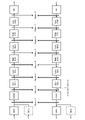
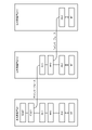
- FIG. 1 is a diagram showing options for functional division of CU (Central Unit) and DU (Distributed Unit).
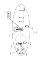
- FIG. 2 is a diagram showing a configuration example of the radio communication system 100.
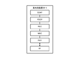
- FIG. 3 is a diagram showing a first configuration example of the base station apparatus 20.
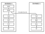
- FIG. 4 is a diagram showing a second configuration example of the base station apparatus 20.
- FIG. 5 is a diagram showing a third configuration example of the base station apparatus 20.
- FIG. FIG. 6 is a diagram showing the configuration of a 5GS (5G System) network architecture.
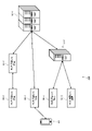
- FIG. 7 is a diagram showing a configuration example of the radio communication system 200.
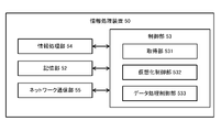
- FIG. FIG. 8 is a diagram showing the configuration of the information processing device 50.
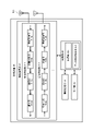
- FIG. 9 is a diagram showing the configuration of a device 60 equipped with RUs.
- FIG. 10 is a diagram showing the configuration of the terminal device 40.
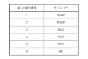
- FIG. 11 is a diagram showing an example of identifying processes in units of sublayers.
- FIG. 12 is a diagram showing another example of identifying processes in units of sublayers.
- FIG. 13 is a diagram showing an example of identifying processes in units of functions or services.
- FIG. 14 is a diagram showing another example of identifying processes in units of functions or services.
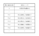
- FIG. 15 is a diagram showing an example of correspondence between devices and second identification information.
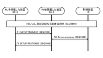
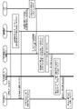
- FIG. 16 is a diagram showing an example of a sequence for setting the F1 interface.
- FIG. 11 is a diagram showing an example of identifying processes in units of sublayers.
- FIG. 12 is a diagram showing another example of identifying processes in units of sublayers.
- FIG. 13 is a diagram showing an example of identifying processes in units of functions or services.
- FIG. 14 is a diagram showing
- FIG. 17 is a diagram showing an example of a sequence for setting the functions of RU, DU and CU.
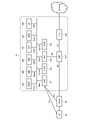
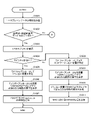
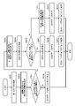
- FIG. 18 is a flowchart showing an example of control of distributed processing in the control device 10 according to the type of communication service.
- FIG. 19 is a flowchart (a continuation of FIG. 18) showing an example of distributed processing control according to the type of communication service in the control device 10 .
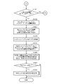
- FIG. 20 is a flowchart (a continuation of FIG. 19) showing an example of control of distributed processing according to the type of communication service in the control device 10.
- FIG. 21 shows an example of the data format.
- FIG. 22 shows another example of the configuration of the control information section.
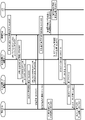
- FIG. 23 shows an example of a data processing sequence for distributed control by the control device 10.
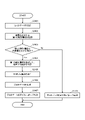
- FIG. 24 is a flow chart showing an example of a processing procedure in the device 60 equipped with RU.
- FIG. 25 is a diagram showing another example of a data processing sequence for distributed control by the control device 10.
- FIG. 26 is a flow chart showing another example of the processing procedure in the device 60 with the RU installed.
- FIG. 27 is a diagram showing still another example of a data processing sequence for distributed control by the control device 10. In FIG.
- A. Overview Figure 1 shows each option of functional division of CU (Central Unit) and DU (Distributed Unit) discussed in 5G extracted from 3GPP TR38.801 "Study on new radio access technology: Radio access architecture and interfaces". showing.
- Option 8 using the CPRI/OBSAI protocol is adopted, and a configuration is defined that divides it into RRH (Remote Radio Head) that processes RF (Radio Frequency) and BBU that processes other L1/L2/L3 functions.
- RRH Remote Radio Head
- RF Radio Frequency
- BBU Radio Frequency
- 5G requires the introduction of a division option that can alleviate this transmission speed. Therefore, in 5G, the configuration is divided into a DU that processes the L2/L1 functions below the RLC (Radio Link Control) sublayer and a CU that processes the L2/L3 functions above the PDCP (Packet Data Convergence Protocol) sublayer, that is, Option 2. Based F1 interface is defined.
- PDCP Packet Data Convergence Protocol
- 5G supports three types of communication modes with significantly different characteristics: eMBB, URLLC, and mMTC.
- B5G Beyond 5G
- an operation of dynamically controlling division of functions other than option 2 is also conceivable.
- FIG. 2 shows a configuration example of a radio communication system 100 .
- a radio communication system 100 includes a control device 10 , a base station device 20 and a terminal device 40 .
- base station device 20 When it is not necessary to distinguish between a plurality of base station devices 20, they are denoted as base station device 20. When they need to be distinguished, they are denoted by a hyphen, such as base station device 20-1 and base station device 20-2. Indicate with a serial number.
- a hyphen and a serial number are used, such as terminal device 40-1 and terminal device 40-2. Append and indicate.
- the control device 10 controls the base station device 20 and controls the terminal device 40 via the base station device 20 .
- the control device 10 is configured, for example, as a function of part or all of the core network.
- the core network referred to here is, for example, EPC (Evolved Packet Core), 5GC (5G Core), and NGC (Next Generation Core).
- the base station device 20-1 operates as a basic coverage cell on the operating frequency f1 and provides the terminal device 40 with wireless communication service coverage on the frequency f1.
- the operating frequency f1 is, for example, frequencies in the 800 MHz band called platinum band, 1.7 GHz, 1.8 GHz, and 2 GHz bands.
- the base station device 20-1 can operate as a gNB (next Generation NodeB) on frequency f1 (first configuration example of the base station device).
- the base station device 20-1 is connected to the base station devices 20-2 and 20-3 via the Fx interface, and operates as a CU for the base station devices 20-2 and 20-3. be able to.
- the Fx interface is an interface corresponding to each split option, including the F1 interface of option 2 shown in FIG.
- the base station device 20-2 operates as a capacity boost cell on the operating frequency f2 and provides wireless communication service coverage on the frequency f2 to the terminal devices 40-2 and 40-3.
- the operating frequency f2 is a frequency band higher than f1, for example, a frequency in a band called a sub-6 GHz band allocated for 5G domestically.
- the base station device 20-2 is connected to the base station device 20-1 operating as the CU via the Fx interface, and can operate as the DU on the frequency f2 (second configuration example of the base station device). .
- the base station device 20-3 operates as a capacity boost cell on the operating frequency f3 and provides the terminal device 40-3 with wireless communication service coverage on the frequency f3.
- the operating frequency f3 is a frequency band higher than f2, for example, a frequency in the millimeter wave band.
- the base station device 20-3 is connected to the base station device 20-1 operating as a CU via the Fx interface, and can operate as a DU on the frequency f3.
- the base station apparatus 20-3 is connected to the base station apparatus 20-2 operating as a DU via an Fx interface, and can operate as an RU (Radio Unit) on frequency f3 (the base station apparatus 20-2). 3 configuration example).
- the base station device 20-3 Since the coverage of the base station device 20-3 operating on the frequency f3 is narrower than the coverage of the base station devices 20-1 and 20-2, the base station device 20-3 is a UE (User Equipment), which will be described later. ) operates as a device close to On the other hand, since the coverage of the base station device 20-1 operating on the frequency f1 is wider than the coverage of the base station devices 20-2 and 20-3, the base station device 20-1 is closer to the core network described later. Works as a device.
- UE User Equipment
- FIG. 3 shows a first configuration example of the base station device 20.
- the base station device 20-1 uses SDAP (Service Data Adaptation Protocol), PDCP (Packet Data Convergence Protocol), RLC (Radio Link Control), MAC (Media Access Control) as a protocol stack for processing the user plane (U-plane). ), PHY (PHYsical) sublayers, and RF (Radio Frequency) for performing signal processing at radio frequencies. That is, the base station device 20-1 has all the functions of CU, DU, and RU in gNB.
- SDAP Service Data Adaptation Protocol
- PDCP Packet Data Convergence Protocol
- RLC Radio Link Control
- MAC Media Access Control
- U-plane User Plane
- PHY Physical sublayers
- RF Radio Frequency
- SDAP provides QoS (Quality of Service) flows for 5GC, mapping between QoS flows and data radio bearers (DRB: Data Radio Bearers), downlink (DL: DownLink) and uplink (UL: UpLink) packets functions or services such as marking QFI (QoS Flow Identifier) for 5GC, mapping between QoS flows and data radio bearers (DRB: Data Radio Bearers), downlink (DL: DownLink) and uplink (UL: UpLink) packets functions or services such as marking QFI (QoS Flow Identifier) for 5GC, mapping between QoS flows and data radio bearers (DRB: Data Radio Bearers), downlink (DL: DownLink) and uplink (UL: UpLink) packets functions or services such as marking QFI (QoS Flow Identifier) for 5GC, mapping between QoS flows and data radio bearers (DRB: Data Radio Bearers), downlink (DL: DownLink) and uplink (UL: UpLink) packets functions or services such as marking QFI (QoS Flow
- PDCP provides radio bearers for SDAP, transfers user plane data or control plane data, manages PDCP SNs (Sequence Numbers), ciphering and deciphering, integrity protection and Functions or services such as integrity verification, timer-based SDU (Service Data Unit) discarding, split bearer routing, data duplication, duplicate discarding, etc. process.
- PDCP SNs Sequence Numbers
- ciphering and deciphering ciphering and deciphering
- integrity protection and Functions or services such as integrity verification, timer-based SDU (Service Data Unit) discarding, split bearer routing, data duplication, duplicate discarding, etc. process.
- SDU Service Data Unit
- RLC provides an RLC channel for PDCP, transfers upper layer PDUs (Protocol Data Unit), assigns independent sequence numbers to PDCP for UM (Unacknowledged Mode) and AM (Acknowledged Mode), ARQ in AM Error correction via (Automatic Repeat reQuest), segmentation of RLC SDUs in UM and AM, re-segmentation in AM, reassembly of SDUs in UM and AM, detection of duplication of data in AM, UM, Handles functions or services such as SDU discard in AM, RLC reassembly, protocol error detection in AM.
- PDUs Protocol Data Unit
- AM Acknowledged Mode
- ARQ in AM Error correction via Automatic Repeat reQuest
- MAC provides logical channels to RLC, mapping between logical channels and transport channels, error correction via HARQ (Hybrid ARQ), control of priority between UEs by dynamic scheduling, prioritization of logical channels It handles functions or services such as priority control between UEs by UE and priority control between overlapping resources within a UE.
- logical channels are defined according to the type of information they carry, and are classified into control channels and traffic channels.
- PHY provides transport channel to MAC, CRC (Cyclic Redundancy Check) and transport block error indication, FEC (Forward Error Correction) and rate matching, data modulation, mapping to physical resources, multi-antenna processing, L1 Handles functions or services such as support for control and HARQ related signaling.
- a transport channel here is defined in terms of how or with what characteristics information is transferred over the air interface.
- FIG. 4 shows a second configuration example of the base station device 20.
- the base station device 20-1 can operate as a gNB by itself, and functions as a CU that processes SDAP and PDCP functions or services with respect to the base station device 20-2 that operates as a DU. can also work.
- the base station apparatus 20-2 is provided with RLC, MAC, and PHY sublayers and an RF that performs signal processing at radio frequencies, and can operate as a DU.
- the PDCP of the base station apparatus 20-1 that also operates as a CU and the RLC of the base station apparatus 20-2 that operates as a DU are connected via an F1 interface.
- This F1 interface is connected, for example, by an optical fronthaul.
- This F1 interface may also be implemented in a wireless fronthaul.
- the PDCP of the base station device 20-1 can provide communication services to the terminal device 40-1 via bearers processed by the lower sublayers (RLC, MAC, PHY) of the base station device 20-1.
- RLC lower sublayers
- the PDCP of the base station device 20-1 constructs a split bearer as a mobility anchor, and the first split bearer processed by the lower sublayers (RLC, MAC, PHY) of the base station device 20-1, and the base station device 20-1. It constitutes a second split bearer processed by the lower sublayers (RLC, MAC, PHY) of the station device 20-2.
- the terminal device 40-2 sets DC (Dual Connectivity) with the base station device 20-1 as the MN (Master Node) and the base station device 20-2 as the SN (Secondary Node), and establishes the first split bearer and the second split bearer. Communication services can be received via two split bearers.
- FIG. 5 shows a third configuration example of the base station device 20.
- the base station device 20-2 can operate as a single DU as shown in FIG. It can also work as a part.
- the base station apparatus 20-3 has a PHY sublayer and an RF that performs signal processing on radio frequencies, and can operate as an RU.
- the MAC of the base station device 20-2, which also operates as part of the DU, and the PHY of the base station device 20-3, which operates as the RU, are connected via an Fx interface.
- This Fx interface is connected, for example, by an optical fronthaul.
- This Fx interface may also be implemented in the radio fronthaul.
- the PDCP of the base station device 20-1 constructs a split bearer as a mobility anchor, and the first split bearer processed by the lower sublayers (RLC, MAC, PHY) of the base station device 20-1 and the base station device 20-2 and the lower sublayer (PHY) of the base station apparatus 20-3.
- the terminal device 40-3 sets a DC with the base station device 20-1 as the MN and the base station device 20-3 as the SN, and receives communication services via the first split bearer and the second split bearer. can be done.
- the MAC of the base station device 20-2 operating as part of the DU is Joint transmission/reception by the base station devices 20-2 and 20-3 to the terminal device 40-3 may be controlled.
- each sublayer of the protocol stack that makes up the user plane of the base station is distributed to multiple devices for processing.
- the example shown in FIGS. 3-5 is an example, and variations based on other splitting options are possible.
- the control distributed to a plurality of devices is not limited to being performed statically, and may be performed dynamically.
- the target of distributed control is not limited to the unit of the sublayer, and may be the unit of various functions or services that constitute the sublayer.
- FIG. 6 shows the configuration of a 5GS (5G System) network architecture.
- 5GS is composed of UE 40 , (R)AN (Radio Access Network/Access Network) 20 and core network 30 .
- UE 40 corresponds to terminal device 40 .
- (R)AN 20 is a network function (NF: Network Function) corresponding to the base station apparatus 20 .
- the control device 10 may be the core network 30 or one of the network functions of the core network 30, for example, an AMF 301 described later. Further, the control device 10 is a device that manages OAM (Operations, Administration and Maintenance), and may control the base station device 20 via the network functions of the core network 30 .
- OAM Order, Administration and Maintenance
- the UDM 307 includes a UDR (Unified Data Repository) that holds and manages subscriber information and an FE (Front End) that processes subscriber information. Also, the AMF 301 performs mobility management. The SMF 306 performs session management. UCMF 310 holds UE radio capability information (UE Radio Capability Information) corresponding to all UE radio capability IDs (UE Radio Capability IDs) in PLMN (Public Land Mobile Network). UCMF 310 is responsible for assigning each PLMN-assigned UE Radio Capability ID.
- UE Radio Capability Information UE Radio Capability Information
- PLMN Public Land Mobile Network
- Namf is the service-based interface provided by the AMF 301
- Nsmf is the service-based interface provided by the SMF 306
- Nnef is the service-based interface provided by the NEF 302
- Npcf is the service-based interface provided by the PCF 305
- Nudm is a service-based interface provided by the UDM 307
- Naf is a service-based interface provided by the AF 308
- Nnrf is a service-based interface provided by the NRF 303
- Nnssf is a service-based interface provided by the NSSF 304
- Nausf is a service-based interface provided by the AUSF 309.
- Each NF exchanges information with other NFs via each service-based interface.
- a UPF User Plane Function
- a DN Data Network
- MNO Mobile Network Operator
- the (R)AN 20 has a function that enables connection with a RAN (Radio Access Network) and connection with an AN (Access Network) other than the RAN.
- the (R)AN 20 includes a base station device 20 called gNB or ng-eNB.
- RAN may also be referred to as NG (Next Generation)-RAN.
- Information is mutually exchanged between the UE 40 and the AMF 301 via the reference point N1.
- Information is exchanged between the (R)AN 20 and the AMF 301 via the reference point N2.
- Information is mutually exchanged between the (R)AN 20 and the UPF 330 via the reference point N3.
- Information is mutually exchanged between the SMF 306 and the UPF 330 via the reference point N4.
- FIG. 7 shows a configuration example of a radio communication system 200 .
- the wireless communication system 200 is composed of an information processing device 50 , a device 60 equipped with an RU, and a terminal device 40 .
- information processing device 50 When it is not necessary to distinguish between a plurality of information processing devices 50, they are indicated as information processing device 50.
- a hyphen such as information processing device 50-1 and information processing device 50-2. Indicate with a serial number.
- the device 60 with RUs it is referred to as the device 60 with RUs.
- a hyphen and a serial number are added to indicate the device 60-2.
- the information processing device 50-1 is, for example, a cloud server or a server installed in a data center.
- the information processing device 50-1 operates as the control device 10.
- the control device 10 is configured as a function of part or all of the core network 30, for example.
- the information processing device 50-2 is, for example, a device called an edge server.
- the information processing device 50-1 operating as the control device 10 can statically or dynamically implement part or all of the functions of the CU and the DU in the information processing device 50-2.
- This dynamic implementation is realized, for example, by utilizing virtualization or container technology.
- the virtualization referred to here is a technology that is launched by a hypervisor and builds an execution environment independent of the host OS by installing a guest OS (Operating System) and applications in the virtual environment.
- the container referred to here is a technology that isolates or restricts the resources of the host OS as a process dedicated to the container, and builds an independent execution environment by changing the attributes of the resources secured when executing the application on the container. is.
- the RU-equipped device 60 may be one device (RU-equipped device 60-1) or a plurality of devices (RU-equipped device 60-2 and RU-equipped device 60-3, or information processing device 50- 2 and RU can be operated as the base station device 20 by the device 60-4).
- the information processing device 50-1 operating as the control device 10 can statically or dynamically implement part or all of the functions of the CU and DU in the device 60 with the RU. This dynamic implementation is realized, for example, by utilizing the virtualization or container technology described above.
- FIG. 8 shows the configuration of the information processing apparatus 50 .
- the information processing device 50 operates, for example, as the control device 10 and statically or dynamically implements part or all of the functions of the CU and DU in the device 60 with the RU.
- FIG. 8 shows the functional configuration of the information processing device 50, and the actual hardware configuration of the information processing device 50 may differ from that of FIG. 8, such as by including functional modules other than those shown. .
- the storage unit 52 functions as storage means for the information processing device 50 .
- the storage unit 52 is composed of data readable and writable storage devices such as DRAM (Dynamic Random Access Memory), SRAM (Static RAM), flash memory, HDD (Hard Disc Drive), and SSD (Solid State Drive). be done.
- DRAM Dynamic Random Access Memory
- SRAM Static RAM
- flash memory HDD (Hard Disc Drive)
- SSD Solid State Drive
- the control unit 53 is a controller that comprehensively controls each unit in the information processing device 50, and is composed of processors such as a CPU (Central Processing Unit) and an MPU (Micro Processing Unit).
- processors such as a CPU (Central Processing Unit) and an MPU (Micro Processing Unit).
- the control unit 53 is implemented by the processor executing various programs stored in the storage unit 52 such as an HDD or SSD using a RAM (Random Access Memory) or the like as a work area.
- the control unit 53 may be configured by an integrated circuit such as ASIC (Application Specific Integrated Circuit) or FPGA (Field Programmable Gate Array). CPUs, MPUs, ASICs, and FPGAs can all be considered controllers.
- the control unit 53 may be configured by a GPU (Graphics Processing Unit) in addition to or instead of the CPU.
- the control unit 53 includes an acquisition unit 531 , a virtualization control unit 532 and a data processing control unit 533 .
- Each of these functional blocks constituting the control unit 53 may be a software block or a hardware block.
- it may be a software module realized by software (including microprograms) or one circuit block on a semiconductor chip (die).
- each functional block may be one processor or one integrated circuit.
- the control unit 53 may be configured in units of functions different from the functional blocks described above, and the method of configuring the functional blocks is arbitrary.
- the information processing section 54 performs necessary calculations according to instructions from the control section 53 .
- the information processing unit 54 is configured by a processor such as a CPU, MPU, or GPU, for example.
- the information processing section 54 may be a processor separate from the control section 53 or may be a processor integrated with the control section 53 .
- the network communication unit 55 is connected to the device 60 equipped with the RU via the fronthaul.
- the fronthaul can be implemented by means of an optical fronthaul or a radio fronthaul, operating as an F1 interface or an Fx interface.
- the network communication unit 55 is connected to another information processing device 50 via a backhaul.
- the backhaul consists of means such as an optical backhaul or a radio backhaul, and exchanges various Application Protocol messages and user plane data with the core network 30 and control information with the control device 10 .
- the acquisition unit 531 acquires Application Protocol messages and user plane data from other information processing devices 50 via the network communication unit 55 . Also, the acquisition unit 531 acquires a program for processing functions or services necessary for operating as a CU or DU from the control device 10 via the network communication unit 55 and stores the program in the storage unit 52 . A function or service required to operate as a CU or DU may consist of multiple functional blocks, and a program for processing the function or service may be implemented in the form of multiple software modules. Furthermore, the acquisition unit 531 acquires control information and user plane data from the other information processing device 50 and the device 60 on which the RU is mounted via the network communication unit 55 .
- the virtualization control unit 532 implements in the information processing unit 54 a program for processing functions or services necessary for operating as a CU or DU according to control information from the control device 10 . Implementation of a program that handles this function or service may be done dynamically. If a program for processing functions or services required to operate as a CU or DU is already stored in the storage unit 52, the virtualization control unit 532 extracts the A necessary software module is selected and installed in the information processing unit 54 . Implementation of this software module is achieved by utilizing the above-described virtualization or container technology. Here, the control information from the control device 10 is notified via an Application Protocol message, for example.
- the information processing unit 54 processes functions or services necessary for operating as a CU or DU for the acquired user plane data according to instructions from the data processing control unit 533. to run.
- the functions or services required to operate as a CU are, for example, one or more functions or services processed in each sublayer of SDAP and PDCP.
- the functions or services required to act as a DU are, for example, one or more functions or services processed in the RLC, MAC or PHY sublayers.
- Functions or services required to operate as an RU are, for example, functions or services processed by the PHY.
- the data processing control unit 533 selects a function or service to be processed in each sublayer according to control information from the control device 10, and executes processing corresponding to the selected function or service for each user plane data. 54.
- the control information from the control device 10 may be added to the user plane data, for example, notified to the information processing device 50 as header information.
- each function or service processed in each sublayer can be distinguished by the first identification information, and the control device 10 notifies each information processing device 50 of the first identification information so that the data A function or service that needs to be processed for each user plane data can be instructed to the processing control unit 533 .
- the information processing device 50 can be distinguished by the second identification information, and the control device 10 notifies the information processing device 50 of the second identification information so that each information processing device 50 has a different function or function. Execution of service processing can be instructed. Therefore, among CUs, DUs, or RUs that need to be processed as one base station device 20, the control device 10 can distribute each processing of the CU or DU to the information processing device 50, and the user plane data You can specify different distributed processing settings for each.
- the identification information is, for example, in the form of an identifier (ID: Identifier) or Human-Readable Name.
- FIG. 9 shows the configuration of a device 60 with RUs.
- a device 60 equipped with an RU is composed of a communication section 61 , a storage section 62 , a control section 63 , an information processing section 64 and a network communication section 65 .
- FIG. 9 shows the functional configuration of the device 60 on which the RU is mounted, and the actual hardware configuration may differ from this. Also, the functionality of the RU-equipped device 60 may be distributed and implemented in multiple physically separate configurations.
- the wireless communication unit 61 is a signal processing unit for wirelessly communicating with another wireless communication device (for example, the terminal device 40).
- the wireless communication section 61 operates under the control of the control section 63 .
- the radio communication unit 61 supports one or more radio access schemes.
- the wireless communication unit 61 supports both NR (New Radio) and LTE (Long Term Evolution).
- the wireless communication unit 61 may support W-CDMA (Wideband Code Division Multiple Access) and cdma2000 in addition to NR and LTE.
- the wireless communication unit 61 may support automatic retransmission techniques such as HARQ.
- the wireless communication unit 61 includes a reception processing unit 611, a transmission processing unit 612, and an antenna 613.
- the wireless communication unit 61 may have a plurality of communication sets each including a reception processing unit 611 , a transmission processing unit 612 and an antenna 613 .
- the configuration may be such that a separate communication set is provided for each wireless access method.
- the reception processing unit 611 and the transmission processing unit 612 may be individually configured for LTE and NR.
- the antenna 613 may be composed of a plurality of antenna elements (for example, a plurality of patch antennas).
- the wireless communication unit 61 may be configured to be capable of beam forming.
- the radio communication unit 61 may be configured to be capable of polarization beamforming using vertical polarization (V polarization) and horizontal polarization (H polarization).
- the reception processing unit 611 includes a radio reception unit 611a, a demultiplexing unit 611b, a demodulation unit 611c, and a decoding unit 611d, and processes uplink signals received via the antenna 613.
- the radio reception unit 611a performs down-conversion, removal of unnecessary frequency components, control of amplification level, orthogonal demodulation, conversion to digital signals, removal of guard intervals (cyclic prefixes), and high-speed reception of uplink signals. Performs extraction of frequency domain signals by Fourier transform.
- the demultiplexing unit 611b demultiplexes uplink channels such as PUSCH (Physical Uplink Shared Channel) and PUCCH (Physical Uplink Control Channel) and uplink reference signals from the signal subjected to these processes.
- the demodulator 611c demodulates the received signal using a modulation scheme such as BPSK (Binary Phase Shift Keying) or QPSK (Quadrature Phase Shift Keying) for the modulation symbols of the uplink channel.
- the modulation scheme used for demodulation may be 16QAM (Quadrature Amplitude Modulation), 64QAM, or 256QAM. In this case, the signal points on the constellation do not necessarily have to be equidistant.
- the constellation may be a non-uniform constellation (NUC).
- NUC non-uniform constellation
- the decoding unit 611d performs decoding processing on the demodulated coded bits of the uplink channel.
- the decoded uplink data and uplink control information are output to the control section 63 .
- the transmission processing unit 612 includes an encoding unit 612a, a modulation unit 612b, a multiplexing unit 612c, and a radio transmission unit 612d, and performs downlink control information and downlink data transmission processing.
- the encoding unit 612a encodes downlink control information and downlink data input from the control unit 63 using an encoding method such as block encoding, convolutional encoding, turbo encoding.
- the encoding may be encoding by polar code or encoding by LDPC code (Low Density Parity Check Code).
- the modulation section 612b modulates the coded bits with a predetermined modulation scheme such as BPSK, QPSK, 16QAM, 64QAM, and 256QAM.
- a predetermined modulation scheme such as BPSK, QPSK, 16QAM, 64QAM, and 256QAM.
- the signal points on the constellation do not necessarily have to be equidistant.
- the constellation may be a non-uniform constellation (NUC).
- the multiplexing unit 612c multiplexes the modulation symbols of each channel and the downlink reference signals, and arranges them in predetermined resource elements.
- the radio transmission unit 612d performs various signal processing on the multiplexed signal.
- the radio transmission unit 612d performs conversion to the frequency domain by fast Fourier transform, addition of a guard interval (cyclic prefix), generation of a baseband digital signal, conversion to an analog signal, quadrature modulation, up-conversion, extra Processing such as removal of frequency components and amplification of power is performed.
- a signal generated by the radio transmission unit 612 d is transmitted from the antenna 613 .
- Antenna 613 is an antenna device that mutually converts electric current and radio waves.
- the antenna 613 may be composed of one antenna element (for example, one patch antenna), or may be composed of a plurality of antenna elements (for example, a plurality of patch antennas). If the antenna 613 is composed of a plurality of antenna elements, the wireless communication section 61 may be configured to be capable of beam forming.
- the radio communication unit 61 may be configured to generate directional beams by controlling the directivity of radio signals using a plurality of antenna elements. Note that the antenna 613 may be a dual polarized antenna.
- the radio communication unit 61 may use vertical polarization (V polarization) and horizontal polarization (H polarization) when transmitting radio signals. Then, the wireless communication unit 61 may control the directivity of the wireless signal transmitted using the vertically polarized wave and the horizontally polarized wave.
- the antenna 613 may be an antenna panel composed of one or more antenna elements, and the RU-equipped device 60 may be equipped with one or more antenna panels.
- the RU has two types of antenna panels, a horizontally polarized antenna panel and a vertically polarized antenna panel, or two types of antenna panels, a right-handed circularly polarized antenna panel and a left-handed circularly polarized antenna panel. Can be installed. Also, the RU-equipped device 60 may form and control independent beams for each antenna panel.
- the storage unit 62 is a data readable/writable storage device such as DRAM, SRAM, flash memory, HDD, and SSD.
- the storage unit 62 functions as storage means for the device 60 on which the RU is installed.
- the control unit 63 is a controller that comprehensively controls each unit in the device 60 equipped with the RU.
- the control unit 63 is configured by a processor such as a CPU or MPU, for example.
- the control unit 63 is realized by the processor executing various programs stored in the storage device inside the device 60 equipped with the RU, using the RAM or the like as a work area.
- the control unit 63 may be configured by an integrated circuit such as ASIC or FPGA. CPUs, MPUs, ASICs, and FPGAs can all be considered controllers.
- the control unit 63 may be configured by a GPU in addition to the CPU or instead of the CPU.
- the control unit 63 includes an acquisition unit 631 , a virtualization control unit 632 and a data processing control unit 633 .
- Each of these functional blocks constituting the control unit 63 may be a software block realized by software (including a microprogram), or a hardware block realized by a circuit on a semiconductor chip (die). may Of course, each functional block may be one processor or one integrated circuit.
- the control unit 63 may be configured in units of functions different from the functional blocks described above, and the method of configuring the functional blocks is arbitrary.
- the information processing section 64 performs calculations necessary for the reception processing section 611 and the transmission processing section 612 according to instructions from the control section 63 .
- the information processing section 64 is configured by a processor such as a CPU, MPU, or GPU, for example.
- a processor separate from the control unit 63 may be used, or a processor integrated with the control unit 63 may be used.
- the network communication unit 65 is connected to the information processing device 50-2 and other RU-mounted devices 60 via the fronthaul.
- the fronthaul consists of an optical fronthaul or a radio fronthaul and operates as an F1 interface or an Fx interface.
- the network communication unit 65 is connected to the information processing device 50-1 via a backhaul.
- the backhaul consists of an optical backhaul or a radio backhaul, and exchanges various Application Protocol messages and user plane data with the core network 30 and control information with the control device 10 .
- the acquisition unit 631 acquires Application Protocol messages and user plane data from the information processing device 50-1 via the network communication unit 65. Also, the acquisition unit 631 acquires a program for processing functions or services necessary for operating as a CU, DU, or RU from the control device 10 via the network communication unit 65 and stores it in the storage unit 62 . A function or service required to operate as a CU, DU, or RU may consist of multiple functional blocks, and a program for processing the function or service may be implemented in the form of multiple software modules. good. Furthermore, the acquisition unit 631 acquires control information and user plane data from the device 60 having another RU via the network communication unit 65 .
- the virtualization control unit 632 implements in the information processing unit 64 a program for processing functions or services necessary for operating as a CU, DU, or RU according to control information from the control device 10 . Implementation of a program that handles this function or service may be done dynamically. If a program for processing functions or services required to operate as a CU, DU, or RU is already stored in the storage unit 62, the virtualization control unit 632 stores the program according to the control information from the control device 10. A necessary software module is selected from the unit 62 and installed in the information processing unit 64 . Implementation of this software module is achieved by utilizing the above-described virtualization or container technology. Here, the control information from the control device 10 is notified via an Application Protocol message, for example.
- the information processing unit 64 follows the instruction from the data processing control unit 633 and acquires functions or services necessary to operate as a CU, DU, or RU for the acquired user plane data.
- the functions or services required to operate as a CU are, for example, one or more functions or services processed in each sublayer of SDAP and PDCP.
- the functions or services required to act as a DU are, for example, one or more functions or services processed in the RLC, MAC or PHY sublayers.
- the functions or services required to act as an RU are, for example, one or more functions or services processed in the PHY sublayer.
- the data processing control unit 633 selects a function or service to be processed in each sublayer according to control information from the control device 10, and executes processing corresponding to the selected function or service for each user plane data. 64.
- the control information from the control device 10 may be added to the user plane data, for example, may be notified to the device 60 in which the RU is installed as header information.
- each function or service processed in each sublayer can be distinguished by the first identification information. Therefore, the control device 10 notifies the device 60 on which each RU is installed of the first identification information, thereby instructing the data processing control unit 633 of the function or service that needs to be processed for each user plane data. be able to. Additionally, each RU-equipped device 60 can be distinguished by a second identification. Therefore, by notifying the second identification information to the device 60 with the RU, the control device 10 can instruct the device 60 with the RU to execute a different function or service process. Therefore, the control device 10 distributes each process of CU, DU, or RU that needs to be processed as one base station device 20 to the device 60 equipped with a plurality of RUs or the information processing device 50-2.
- one device can be regarded as the base station device 20 .
- FIG. 10 shows the configuration of the terminal device 40 .
- the terminal device 40 is composed of a communication section 41 , a storage section 42 , a control section 43 and an information processing section 44 .
- FIG. 10 shows the functional configuration of the terminal device 40, and the actual hardware configuration of the terminal device 40 may differ from that of FIG. 10, such as by including functional modules other than those shown. Also, the functions of the terminal device 40 may be distributed and implemented in a plurality of physically separated configurations.
- the wireless communication unit 41 is a signal processing unit for wirelessly communicating with other wireless communication devices (eg, base station 20, relay station, wireless communication node or donor node, and other terminal device 40).
- the radio communication section 41 operates under the control of the control section 43 .
- the wireless communication section 41 includes a reception processing section 411 , a transmission processing section 412 and an antenna 413 .
- the configurations of the wireless communication unit 41, the reception processing unit 411, the transmission processing unit 412, and the antenna 413 are the same as those of the wireless communication unit 61, the reception processing unit 611, the transmission processing unit 612, and the antenna 613 of the device 60 equipped with the RU. may Further, like the wireless communication unit 61, the wireless communication unit 41 may be configured to be capable of beamforming.
- the storage unit 42 is a data readable/writable storage device such as a DRAM, SRAM, flash memory, or hard disk.
- the storage unit 42 functions as storage means of the terminal device 40 .
- the storage unit 42 stores in advance programs for processing necessary functions or services corresponding to the processing executed by the CU, DU, or RU.
- the control unit 43 is a controller that controls each unit of the terminal device 40 .
- the control unit 43 is configured by a processor such as a CPU or MPU, for example.
- the control unit 43 is realized by the processor executing various programs stored in the storage device inside the terminal device 40 using the RAM or the like as a work area.
- the control unit 43 may be configured by an integrated circuit such as an ASIC or FPGA. CPUs, MPUs, ASICs, and FPGAs can all be considered controllers.
- the control unit 43 may be configured by a GPU in addition to the CPU or instead of the CPU.
- the control unit 43 includes an acquisition unit 431 and a data processing setting unit 432.
- Each block (acquisition unit 431 and data processing setting unit 432 ) constituting the control unit 43 is a functional block indicating the function of the control unit 43 .
- Each of these functional blocks may be a software block implemented by software (including microprograms), or a hardware block implemented by a circuit on a semiconductor chip (die). Of course, each functional block may be one processor or one integrated circuit.
- the control unit 43 may be configured in units of functions different from the functional blocks described above, and the method of configuring the functional blocks is arbitrary.
- the information processing unit 44 processes calculations necessary for applications executed by the reception processing unit 411, the transmission processing unit 412, or the terminal device 40 according to instructions from the control unit 43.
- the information processing section 44 is configured by a processor such as a CPU, MPU, or GPU, for example.
- a processor separate from the control unit 43 may be used, or a processor integrated with the control unit 43 may be used.
- the acquisition unit 431 acquires control information and user plane data from the base station device 20 or the device 60 with the RU installed via the wireless communication unit 41 .
- the acquisition unit 431 acquires a program for processing a function or service corresponding to the processing executed by the CU, DU, or RU from the control device 10 via the wireless communication unit 41 as necessary. store in If the storage unit 42 already stores a program, it is updated with a newly acquired program.
- a function or service corresponding to processing executed by a CU, DU, or RU may consist of a plurality of functional blocks, and a program for processing the function or service may be implemented in the form of a plurality of software modules. good too.
- the data processing setting unit 432 sets, in the information processing unit 44, a program for processing necessary functions or services corresponding to the processing executed by the CU, DU, or RU according to the control information from the control device 10.
- the configuration of the program that handles this function or service may be done dynamically.
- the control device 10 can instruct the data processing setting unit 432 to set a program for processing different functions or services for each user plane data.
- the data processing setting unit 432 receives the control information from the control device 10.
- the necessary software modules are selected from the storage section 42 according to the control information from the control device 10 and installed in the information processing section 44 .
- the control information from the control device 10 is notified via NAS (Non-Access Stratum) messages, for example.
- the information processing unit 44 executes function or service processing corresponding to the processing executed by the CU, DU, or RU on the acquired user plane data.
- the functions or services corresponding to the processing performed in the CU, DU or RU are, for example, one or more functions or services processed in the SDAP, PDCP, RLC, MAC and PHY sublayers.
- the function or service identification method of each sublayer in addition to the 800 MHz and 2 GHz bands conventionally used in cellular systems, a wide range of frequency bands such as a frequency band called sub-6 GHz and a millimeter wave band of 27 GHz or higher is covered. is required.
- the need for functions such as beamforming, resistance to blocking by moving objects (for example, application of diversity), support for high-speed mobility, etc., is considered to depend on the operating frequency.
- 5G is required to support slices with different requirements for wireless communication, such as eMBB, URLLC, and mMTC. Therefore, it is conceivable to dynamically change the setting of distributed processing for each user plane data according to the operating frequency to be used and the slice to be applied. In addition, we need a way to identify each process.
- FIG. 11 shows an example of identifying processes in units of sublayers.
- Information is pre-assigned.
- FIG. 12 shows another example of identifying processes in units of sublayers.
- “1" in the SDAP sublayer, "2" in the PDCP sublayer, "3” in the High-RLC sublayer, “4" in the Low-RLC sublayer, "5" in the High-MAC sublayer, Low- Different identification information of "6” is assigned to the MAC sublayer, "7” to the High-PHY sublayer, "8” to the Low-PHY sublayer, and "9” to the RF.
- the example shown in FIG. 12 shows an example in which the PHY, MAC, and RLC sublayers are classified into two, Low and High. good too.
- PDCP and SDAP may also be classified into two or more.
- FIG. 13 shows an example of identifying processes in units of functions or services.
- the first identification information consists of identification information 1 that identifies each sublayer and identification information 2 that identifies a function or service, and each function or service is identified by the first identification information.
- the function or service provided by the SDAP sublayer "Mapping between QoS flows and data radio bearers" includes "1" as identification information 1, "1" as identification information 2, and "marking QFI for packets". is assigned "1" as identification information 1 and "2" as identification information 2.
- the function or service provided by the MAC sublayer includes “4" as identification information 1, "1” as identification information 2, and "error correction via HARQ". has “4" as identification information 1, "2" as identification information 2, and "coordinated control by CoMP (Coordinated Multi-Point)” has “4" as identification information 1 and "3” as identification information 2. assigned.
- "mapping to physical resource” which is a function or service provided by the PHY sublayer
- 5", and "2" is assigned as identification information 2.
- each sublayer is identified with the granularity shown in FIG. 11, but each sublayer may be identified with finer granularity as shown in FIG. Alternatively, each sublayer may be defined and identified for each distributed device.
- FIG. 14 shows another example of identifying processes by function or service.
- the first identification information for identifying the function or service provided by each sublayer is assigned flatly to each sublayer without identifying each sublayer with the first identification information.
- “QoS flow to data radio bearer mapping” is assigned a first identification of "1”
- “QFI marking for packets” is assigned a first identification of "2”.
- “Management of PDCP Sequence Number(s)” is assigned "A+1" as first identification information
- Encryption and Decryption is assigned "A+2" as first identification information.
- each of the sublayers, functions, or services illustrated in FIGS. 11 to 14 above may be a network slice instance forming a network slice.
- the first identification information shown in FIGS. 11 to 14 above may be associated with a network slice identifier (eg, Single Network Slice Selection Assistance Identifier (S-NSSAI)).
- the sublayers, functions, or services illustrated in FIGS. 11-14 above may each or in combination constitute a slice in the RAN (eg, a RAN slice).
- the first identification information may be named RAN Slice Identifier, or a plurality of first identification information may be associated with one RAN Slice Identifier.
- one or more RAN Slice Identifiers may be associated with one or more network slice identifiers (eg, Single Network Slice Selection Assistance Identifier (S-NSSAI)).
- S-NSSAI Single Network Slice Selection Assistance Identifier
- the "first identification information" described above or below is the identifier of the network slice associated with the first identification information (for example, Single Network Slice Selection Assistance Identifier (S-NSSAI)) or RAN Slice Identifier may be at least one of, or at least one may be included with the first identification information.
- the above-described or later-described processing and operations using the "first identification information" are the identifier of the network slice associated with the first identification information (for example, Single Network Slice Selection Assistance Identifier (S-NSSAI)), Alternatively, it may be a process or operation using at least one of the RAN Slice Identifiers.
- S-NSSAI Single Network Slice Selection Assistance Identifier
- first identification information is assigned in units of sublayers, functions, or services. 1 identification information allocation is managed.
- the control device 10 may dynamically change the allocation of the first identification information. It instructs the mounted device 60 or the terminal device 40 to change the allocation of the first identification information.
- the information processing device 50-2 has "1" as the second identification information
- the device 60-1 with the RU has "F+1” as the second identification information
- the RU is
- the mounted device 60-2 is assigned “F+2” as the second identification information
- the assignment of the second identification information is managed by the control device 10.
- the radio communication system 200 may be a unit of PLMN or NPN (non-public network).
- the radio communication system 200 may be in units of TN (Terrestrial Network) or NTN (non-Terrestrial Network).
- the control device 10 may dynamically change the allocation of the second identification information, and when changing the allocation of the second identification information, the control device 10 changes the information processing device 50 or the RU It instructs the mounted device 60 to change the assignment of the second identification information.
- Identification information 2 may be assigned for identification, and the second identification information may be constructed from these identification information 1 and identification information 2 .
- the second identification information for identifying each device may be a device identifier defined by 3GPP, or may be a cell identifier served by the device.
- the second identification information for identifying each device may be gNB-DU ID and Global gNB ID defined by 3GPP.
- the gNB-DU ID is an ID that uniquely identifies a gNB-DU within one gNB-CU.
- the identifier of the cell served by each device may be NR CGI (New Radio Cell Global Identifier).
- FIG. 16 shows an example of the sequence for setting the F1 interface.
- the control device 10 allocates devices to be RU, DU, and CU (SEQ1601).
- the control device 10 allocates a device 60-2 equipped with an RU as a device operating as a CU, and allocates a device 60-3 equipped with an RU as a device operating as a DU including an RU. .
- the controller 10 assigns the device 60-2 equipped with the RU with a container including functions or service processing necessary for the operation of the CU. Notifies you of instructions to set the Further, when the control device 10 assigns the device 60-3 equipped with the RU as a device that operates as the DU including the RU, the control device 10 assigns the function or service necessary for the operation of the DU including the RU to the device 60-3 equipped with the RU.
- This notification may include an address (for example, an IP address, a port number, etc.) indicating a device from which the main body of the application that configures the container, the necessary library, the configuration file, and the like.
- the device 60-2 with the RU and the device 60-3 with the RU acquire the application body, necessary libraries, setting files, etc. from the device indicated by this address.
- the device 60-3 equipped with the RU transmits an F1 SETUP REQUEST message to the device 60-2 equipped with the RU (SEQ 1602).
- the device 60-2 equipped with the RU that received the F1 SETUP REQUEST message executes the NG Setup procedure with the control device 10 (SEQ 1603).
- the RU-equipped device 60-2 responds with an F1 SETUP RESPONSE message to the RU-equipped device 60-3 (SEQ 1604), and the RU-equipped device Complete the setup of the F1 interface between 60-3 and RU-equipped device 60-2.
- FIG. 16 shows an example of a sequence for setting the F1 interface. Further, when the RU and DU are divided into a plurality of devices, a device operating as an RU, a device operating as a DU, and a device operating as a CU. With the device, the F1 interface and Fx interface are set according to the same procedure.
- FIG. 17 shows an example of a sequence for setting the functions of RU, DU and CU.
- the control device 10 executes the gNB Configuration Update procedure (SEQ1701) and instructs the device 60-2 with the RU to configure the gNB.
- This gNB setting includes, for example, setting the functions necessary to operate the device 60-2 equipped with the RU as a CU, and setting the device 60-3 equipped with the RU to operate as a DU including the RU. and setting the necessary functions for
- the device 60-2 equipped with the RU according to the settings of the gNB sets the functions necessary to operate as a CU (SEQ1702).
- the setting of the functions required to operate as a CU is performed by sending from the control device 10 to the device 60-2 on which the RU is mounted an identification corresponding to each sublayer shown in FIGS. By posting a list containing the information.
- the device 60-2 with the RU is set so that, for example, the function or service corresponding to the identification information included in this list can be processed as a container.
- the functions required to operate as a CU are functions provided by the SDAP sublayer and the PDCP sublayer, for example.
- the RU-equipped device 60-2 notifies the RU-equipped device 60-3 via a GNB CU CONFIGURATION UPDATE message of an instruction to set the functions necessary to operate as a DU including the RU.
- the setting of the functions necessary to operate as a DU including RUs is performed by providing each sublayer shown in FIGS. by notifying a list containing
- the functions required to operate as a DU including an RU are, for example, functions provided by the RLC sublayer, MAC sublayer, PHY sublayer, and RF.
- the device 60-3 equipped with the RU that received the instruction to set the necessary functions sets the functions necessary to operate as a DU including the RU (SEQ 1704), sends the GNB CU CONFIGURATION UPDATE ACK message, and loads the RU. device 60-2 responds (SEQ1705). Also, if the instruction includes an instruction to set the functions necessary for operating as an RU in another device, the device 60-3 equipped with the RU sets the functions necessary for operating as a DU, Furthermore, it notifies another device of an instruction to set the functions necessary to operate as an RU.
- the control device 10 can use the gNB Configuration Update procedure to dynamically set the necessary functions for the RU-equipped device 60-2 and the RU-equipped device 60-3.
- the example shown in FIG. 17 shows an example in which the functions necessary for setting the gNB are distributed and set in two devices, the device 60-2 equipped with the RU and the device 60-3 equipped with the RU. You may distribute and set to the above apparatus.
- the control device 10 not only causes the device 60-2 equipped with the RU to operate as the CU of the device (the device 60-3 equipped with the RU) that operates as the DU, but also, for example, the base station device shown in FIG. 20-1 may be set so that it can operate as a single gNB at frequency f1.
- the device 60-2 equipped with RU is set with the functions necessary to operate as a single gNB, and an interface (eg, F1 interface) with another device (device 60-3 equipped with RU). By constructing it, it can also act as a CU for other devices.
- control device 10 controls the setting of the functions necessary to operate as a DU including the RU for the device 60-2 mounted with the RU for which the functions necessary to operate as the CU are set. You may allow it. Based on this permission, the device 60-2 equipped with the RU, according to the state of the terminal device 40 (for example, mobility), sets the functions necessary to operate as a DU including the RU. The device can be determined. Further, the device 60-2 equipped with the RU can determine another device to execute processing of functions or services required by the RU or DU according to the type of user plane data received.
- 18 to 20 show an example of distributed processing control according to the type of communication service in the control device 10 in the form of a flowchart.
- the control device 10 checks the type of user plane data (step S1801) and determines whether it is data for a highly reliable/low-delay communication service (step S1802). Here, if the type of user plane data is data for a high-reliability/low-delay communication service (Yes in step S1802), the control device 10 further confirms the mobility of the UE (terminal device 40) (step S1803), it is determined whether the mobility of the UE is low (step S1804).
- control device 10 identifies a device close to the UE (for example, device 60-4 with RU) as a mobility anchor (step S1805).
- a device close to the UE for example, device 60-4 with RU
- Duplication processing is added to the sublayer processing (step S1807), and this processing ends. In this way, the control device 10 causes a device close to the UE to execute duplication processing, thereby reducing traffic on the backhaul and fronthaul.
- control device 10 may add forward error correction (FEC) processing instead of duplication processing, depending on the delay required for the communication service. For example, if the requested delay is less than or equal to a certain threshold, FEC processing is added in step S1807.
- the delay required for the communication service is determined, for example, by PDB (Packet Delay Budget).
- Whether or not to add FEC processing in step S1807 is determined based on information as to whether the UE has a function of processing FEC. Information as to whether the UE has the capability to process FEC is obtained, for example, through capability information of the UE.
- the control device 10 identifies a device (for example, the information processing device 50-2) close to the core network 30 as a mobility anchor (step S1808).
- a device close to the core network 30 is specified as a mobility anchor in this way is that if a device close to the UE is set as a mobility anchor, it is necessary to frequently switch the mobility anchor according to the movement of the UE. is.
- the control device 10 determines execution of functions required in sublayers above the RLC sublayer (that is, SDAP, PDCP, and RLC) in a device serving as a mobility anchor (device close to the core network 30) (step S1809). ), determine execution of functions required in sublayers below the MAC sublayer (that is, MAC, PHY, RF) in a device close to the UE (eg, the device 60-4 equipped with the RU) (step S1810). Then, in order to improve reliability, the control device 10 adds HARQ processing to the processing in the MAC sublayer (step S1811), and ends this processing.
- the PDCP sublayer may also use duplication within a range that fronthaul traffic can tolerate.
- a split bearer is set for each device to set duplication without increasing fronthaul traffic. can do.
- FIG. 19 shows the processing procedure when it is determined that the data is not for the high-reliability/low-delay communication service (No in step S1802). If it is determined that the data is not for the high-reliability/low-delay communication service, then the control device 10 determines whether or not the data is for the high-speed, large-capacity communication service (step S1821).
- the control device 10 can set multi-connectivity for improving the data rate, the core network as a mobility anchor. 30 (for example, the information processing device 50-2) is identified (step S1822). Subsequently, the control device 10 determines execution of a function required in the PDCP sublayer by a device serving as a mobility anchor (device close to the core network 30) (step S1823). Subsequently, the control device 10 checks the UE's capability and mobility (step S1824), and identifies a plurality of devices for setting Multi Connectivity based on the UE's capability and mobility (step S1825).
- the control device 10 confirms the configuration of the wireless communication unit 41 of the terminal device 40 via the UE capability information. If the terminal device 40 can operate in multiple frequency bands at the same time, it decides to set the Multi Connectivity, and identifies multiple devices for which the Multi Connectivity is set based on the mobility.
- the wireless communication unit 41 supports operation in the 800 MHz band, 1.7 GHz, 1.8 GHz, or 2 GHz band such as the frequency f1 described above and the millimeter wave band such as the frequency f3, and the mobility is low.
- the multiple devices for which Multi Connectivity is set are the device 60 equipped with an RU operable on the frequency f1 and the device 60 equipped with an RU operable on the frequency f3.
- the wireless communication unit 41 supports operation in the sub-6 GHz band such as the frequency f1 and the frequency f2 described above, and the mobility is high, multiple devices that set Multi Connectivity A device 60 equipped with an RU that can operate and a device 60 equipped with an RU that can operate at the frequency f2.
- the control device 10 determines execution of functions required in sublayers below the RLC (that is, RLC, MAC, PHY, RF) in the specified plurality of devices, and sets Multi Connectivity (step S1826). .
- the control device 10 determines the mobility of the UE (step S1827). Then, when the mobility of the UE is low (Yes in step S1827), if multiple RUs are installed, the MAC sublayer processing in the device 60 equipped with RUs capable of operating at frequency f3 is performed by CoMP processing. After adding (step S1828), the process ends. Also, if the mobility of the UE is not low (No in step S1827), this process ends.
- control device 10 may determine whether it is indoors. Generally, indoors, the mobility of the UE is low. Therefore, for example, if the UE is equipped with a plurality of RUs, the control device 10 performs the processing of the MAC sublayer in the device 60 equipped with the RU that can operate on the frequency f3. Add CoMP processing.
- FIG. 20 shows the processing procedure when it is determined that the data is not for the high-speed large-capacity communication service (No in step S1821).
- the control device 10 determines that the user plane data is data for a multiple simultaneous connection communication service, confirms the number of simultaneous connections (step S1831), and confirms the number of simultaneous connections. It is determined whether or not the number of connections is equal to or less than the threshold (step S1832).
- control device 10 identifies a device (for example, information processing device 50-2) close to core network 30 as a mobility anchor (step S1833). Then, control device 10 determines execution of functions required by sublayers below the PDCP sublayer (that is, PDCP, RLC, MAC, PHY, and RF) in a device that serves as a mobility anchor (device close to core network 30). (step S1834), and the process ends.
- a device for example, information processing device 50-2
- control device 10 determines execution of functions required by sublayers below the PDCP sublayer (that is, PDCP, RLC, MAC, PHY, and RF) in a device that serves as a mobility anchor (device close to core network 30).
- the control device 10 decides to distribute the devices serving as mobility anchors to a plurality of devices (step S1835). For example, the control device 10 decides to distribute the devices serving as mobility anchors to the device 60-4 with the RU and the device 60-5 with the RU. Then, the control device 10 uses sublayers below the PDCP sublayer (that is, PDCP, RLC, MAC, PHY , RF) to execute the necessary functions (step S1834), and the process ends.
- sublayers below the PDCP sublayer that is, PDCP, RLC, MAC, PHY , RF
- the control device 10 prioritizes each type of user plane data among various criteria such as delay, reliability, data rate, and number of simultaneous connections. This enables dynamic distributed control according to certain criteria. Based on criteria prioritized for each type of user plane data and the mobility of the UE, a device serving as a mobility anchor can be specified, and a necessary function can be executed in the PDCP sublayer. In addition, the control device 10 controls multiple antennas such as CoMP, MIMO (Multiple Input Multiple Output), diversity, etc. based on criteria prioritized for each type of user plane data, and UE mobility and capability, and a MAC that processes HARQ.
- criteria prioritized for each type of user plane data and the mobility of the UE can be specified, and a necessary function can be executed in the PDCP sublayer.
- the control device 10 controls multiple antennas such as CoMP, MIMO (Multiple Input Multiple Output), diversity, etc. based on criteria prioritized for each type of user plane data, and UE mobility and capability, and a MAC that processes HARQ.
- Functions required in sub-layers can be selectively added and executed by a device serving as a mobility anchor or distributed to another device.
- a device serving as a mobility anchor or distributed to another device.
- distributed processing is performed by a plurality of devices in units of sublayers illustrated in FIG. 11 has been described, but the present disclosure is not limited to this example.
- distributed processing may be performed by a plurality of devices in units of groups smaller than sublayers, or as shown in FIG. Distributed processing may be used.
- distributed control for each type of user plane data may be set for each BWP (BandWidth Part).
- a BWP is a set of consecutive PRBs (Physical Resource Blocks), multiple BWPs can be set at any carrier frequency, and a different numerology (subcarrier interval, symbol period, Cyclic Prefix length) for each BPW ) can be set.
- the distributed control for each type of user plane data may be the same setting for the downlink and the uplink. - When transmitting data for a low-delay communication service, different settings may be made independently for the downlink and uplink. Further, when the terminal device 40 simultaneously receives a plurality of communication services with different types of user plane data, the control device 10 may set different distributed control for each type of user plane data.
- FIG. 21 shows an example of the data format. An example of a data format is shown. As shown in FIG. 4A, user plane data transferred from the core network 30 is composed of a control information section and a data section.
- FIG. 21(b) shows an example of the configuration of the control information section.
- the control information section is composed of information (second identification information) that identifies a device that executes distributed processing, and information (first identification information) that identifies a function or service processed by each device that performs distributed processing. be.
- the device 60-2 equipped with the RU processes the SDAP sublayer and PDCP sublayer for the data in the data section.
- a device 60-3 equipped with an RU performs RLC sublayer, MAC sublayer, PHY sublayer, and RF processing.
- the control information part is means for notifying which device is to execute each process of a plurality of functions or services required for operation as a base station, and can be controlled at the granularity of data packets.
- FIG. -3 Another example of the control information part shown in FIG. -3 is an example of the control information part added to the data transferred to .
- the device 60-2 equipped with the RU obtains the second identification information corresponding to the own device and the first identification information corresponding to the function or service processed by the own device from the control information section shown in FIG. 21(b). 21(c) to generate the control information part shown in FIG.
- FIG. 21(b) an example of the control information part for distributed processing in units of sublayers is shown, but as shown in FIG.
- FIG. 13 or 14 it may be a control information section containing identification information for performing distributed processing in units of functions or services.
- the information contained in the control information part is terminated between the UPF 330 and the information processing device 50 or each device 60 equipped with RUs, or between each device 60 equipped with RUs.
- the data part shown in FIG. 21(a) is, for example, an SDAP PDU after performing SDAP sublayer processing, a PDCP PDU after performing PDCP sublayer processing, and an RLC PDU after performing RLC sublayer processing. , or MAC PDU after executing MAC sublayer processing.
- the SDAP PDU is an upper layer IP packet that is a QoS flow, to which a header including QFI, RDI (Reflective QoS flow to DRB mapping indication), RQI (Reflective QoS indication), etc. is added.
- a PDCP PDU is an SDAP PDU of the SDAP sublayer with a header including a sequence number (SN: Sequence Number).
- An RLC PDU is a PDCP PDU of the PDCP sublayer with a header including a sequence number (SN), segment information (Segment Information), and segment offset (Segment Offset).
- a MAC PDU is the RLC PDU of the RLC sublayer with a header including a logical channel ID (LCID: Logical Channel ID), MAC CE (Control Element), etc. added.
- the device 60 equipped with the RU can use this MAC CE to notify the terminal device 40 of control information that is necessary when executing processing of the MAC sublayer. That is, the MAC CE is terminated between the respective MACs of the device operating as the base station and the terminal device 40 .
- each sublayer PDU is obtained by adding a header including a sequence number, segment information, CE (Control Element), etc. to a PDU obtained from another device. That is, the PDUs for each sublayer can vary depending on how the functions or services required for the operation of the base station are distributed to each device.
- Each device can use the CE to notify the terminal device 40 of control information necessary for executing the process assigned to the device. That is, the CE is terminated between each device operating as part of the base station and the terminal device 40 .
- the sublayers defined for each distributed device are grouped and managed by group ID.
- the sublayers corresponding to each group ID constitute a first set of identification information corresponding to one or more functions or services shown in FIG.
- the control device 10 uses the gNB Configuration Update procedure shown in FIG.
- Each device can recognize one or more features or services to be configured.
- the control device 10 or the UPF 330 selects one or more functions or services corresponding to the type of the user plane data from the set including the group ID and the first identification information corresponding to the group ID.
- each device can recognize one or more functions or services selected according to the type of user plane data and execute distributed processing. .
- FIG. 22 shows another example of the configuration of the control information section.
- third identification information indicating whether or not to permit transfer of each process indicated by the first identification information to another apparatus.
- Each device can transfer each process indicated by the first identification information to another device when the third identification information permits the transfer to another device.
- each designated process can be transferred to another apparatus according to the remaining processing capacity of the own apparatus.
- each device can replace the second identification information with information identifying the transfer destination device.
- the control device 10 selects a function or service that needs to be processed by the base station for each user plane data transmitted and received by the terminal device 40, and uses a set of identification information corresponding to the selected function or service as control information. Add to each user plane data.
- the set of identification information may be generated for each device operating as a base station or a part thereof, for example, in the form of a list including identification information corresponding to functions or services selected for each device. good. For example, each device is set so that functions or services corresponding to identification information included in this list can be processed as containers.
- FIG. 23 shows an example of a data processing sequence for distributed control by the control device 10.
- the control device 10 identifies the function to be set for each device (the device 60-2 with the RU and the device 60-3 with the RU) (SEQ2301).
- the control device 10 sets the functions (for example, RLC, MAC, all functions or services of the PHY sublayer, and RF) necessary for the device 60-3 equipped with the RU to operate as a DU, and sets the RU.
- It decides to set the functions (for example, SDAP, PDCP, RLC, MAC, all functions or services of the PHY sublayer, and RF) necessary for the installed device 60-2 to operate as a gNB.
- all functions or services of SDAP, PDCP, RLC, MAC, PHY sublayers are, for example, the functions or services shown in FIGS. 13 and 14.
- FIG. 1 shows the functions or services shown in FIGS. 13 and 14.
- the control device 10 uses the gNB Configuration Update procedure according to the sequence shown in FIG. 17 to instruct the device 60-2 with the RU and the device 60-3 with the RU to set the necessary functions (SEQ2302). .
- the functions required for the device 60-2 equipped with the RU are the functions required for operating as a gNB, and the functions required for the device 60-3 equipped with the RU are required for operating as a DU. function.
- the RU-equipped device 60-2 When the RU-equipped device 60-2 receives the instruction via the gNB Configuration Update procedure (SEQ2302), it sets the functions necessary to operate as a gNB (SEQ2303). Subsequently, the RU-equipped device 60-2 transmits a GNB CU CONFIGURATION UPDATE containing instructions for setting the functions required to operate as a DU to the RU-equipped device 60-3 (SEQ2304).
- the device 60-3 equipped with the RU When the device 60-3 equipped with the RU receives the instruction via the GNB CU CONFIGURATION UPDATE, it sets the functions necessary to operate as a DU (SEQ2305) and sends the GNB CU CONFIGURATION UPDATE ACK message to the RU. It responds to device 60-2 (SEQ2306).
- the device 60-2 equipped with an RU that can operate as a single gNB can simultaneously operate as a CU for the device 60-3 equipped with an RU that operates as a DU.
- device 60-2 with RU and device 60-3 with RU can operate as one base station device 20 in cooperation.
- the control device 10 When the control device 10 receives a connection request from the terminal device 40 (SEQ2307), the control device 10, according to the processing procedure shown in FIGS. , RU (equipment 60-3) is determined (SEQ2308).
- the functions to be executed by the device 60-2 equipped with the RU are, for example, the processing of the SDAP sublayer and the PDCP sublayer, and the functions to be executed by the device 60-3 equipped with the RU are the RLC sublayer, the MAC sublayer, the PHY Sublayer and RF processing.
- the terminal device 40 can transmit a connection request via the device 60-2 equipped with the RU capable of operating as a single gNB based on the default setting.
- the control device 10 transmits, to the terminal device 40, notification of information related to the functions executed by each device operating as a base station in response to data transmitted and received to the terminal device 40 (SEQ2309). This notification may be notified during response processing for the connection request of SEQ2307.
- the connection request of SEQ2307 includes, for example, S-NSSAI (Single-Network Slice Selection Assistance Information), which is information related to network slices, QoS, information related to services and applications, and the like. Therefore, the control device 10 selectively determines the function to be executed by each device for data transmitted and received to and from the terminal device 40 according to the type of user plane data such as network slice, QoS, service or application. distributed processing to multiple devices.
- the terminal device 40 When the terminal device 40 receives the notification of the information related to the function executed by each device operating as the base station (SEQ2309), the terminal device 40 sets the necessary signal processing on the UE side corresponding to the notified function or service (SEQ2310).
- the notification of the information related to the functions executed by each device operating as the base station in SEQ2309 includes, for example, information indicating that HARQ is controlled by the MAC sublayer processed by the device 60-3 equipped with the RU operating as a DU. include.
- the control device 10 notifies the UPF 330 that processes user plane data of information related to the functions executed by each device (SEQ2311).
- the UPF 330 receives the notification of the information related to the functions executed by each device in SEQ2311, it generates a control information part to be added to the data addressed to the terminal device 40 (SEQ2312).
- the control information part added to the data addressed to the terminal device 40 is, for example, the control information part shown in FIG. 21(b).
- the UPF 330 transmits the first data including the control information section generated in SEQ2312 to the device 60-2 equipped with the RU (SEQ2313).
- the second identification information for identifying the device to execute the distributed processing included in the control information part of the first data indicates the own device. and selects the processing of the SDAP sublayer and PDCP sublayer indicated by the first identification information that identifies the function or service to be processed from among the functions of the gNB.
- device 60-2 equipped with the RU executes SDAP sublayer and PDCP sublayer processing on the data portion of the first data to generate second data (SEQ2314).
- the control information part of the second data is, for example, the control information part shown in FIG. 21(c), and the data part is PDCP PDU.
- the device 60-2 equipped with the RU transmits the second data addressed to the terminal device 40 generated in SEQ2314 to the device 60-3 equipped with the RU (SEQ2315).
- the RU-equipped device 60-3 identifies the device to execute the distributed processing contained in the control information portion of the second data. Confirm that the identification information indicates the own device, and identify the function or service to be processed from among the set functions RLC sublayer, MAC sublayer, PHY sublayer, and RF indicated by the first identification information choose an action.
- the device 60-3 equipped with the RU performs RLC sublayer, MAC sublayer, PHY sublayer, and RF processing on the data portion of the second data to generate third data (SEQ2316).
- the third data is, for example, data obtained by modulating data in units of transport blocks and assigning the modulated data to resource blocks.
- the device 60-3 equipped with the RU transmits the generated third data addressed to the terminal device 40 to the terminal device 40 (SEQ2317).
- the terminal device 40 executes the signal processing procedure set in SEQ 2310 (SEQ 2318 ) and acquires data from the UPF 330 .
- the control device 10 can dynamically change the processing necessary for the base station to be distributed and executed by two or more devices (the device 60 equipped with the RU and the information processing device 50-2).
- the function or service to be subjected to distributed processing can be changed for each device according to the type of data to be transmitted and received to and from the terminal device 40 .
- the processing of the SDAP sublayer and the PDCP sublayer is distributed to the device 60-2 equipped with the RU, and the processing of the RLC sublayer, the MAC sublayer, the PHY sublayer, and the RF is distributed to the device 60-3 equipped with the RU.
- An example sequence is shown.
- FIG. 23 shows a sequence example in which processing is distributed in units of sublayers, but as shown in FIG. 12, processing may be distributed in units of groups smaller than sublayers. As indicated, processing may be distributed by function or service. In other words, the processing required at the base station is processed on a service basis using multiple devices. Note that the dynamic distributed control described above can be set for each terminal device 40 (UE specific).
- the type of data may be QFI (QoS Flow Identifier), for example. That is, the data type is identified by the QFI that classifies the QoS flow.
- the control device determines the QFI assigned to the QoS flow, and causes each of the two or more devices to execute one of a plurality of processes necessary to operate as a base station based on the determined QFI. The above processing may be selected for each device.
- the data type may be 5QI (5G QoS Identifier), which is a parameter for controlling QoS.
- the data type may be an S-NSSAI that identifies a network slice.
- S-NSSAI is composed of SST (Slice/Service Type) and SD (Slice Differentiator), and the type of data is determined by SST alone or by SST and SD.
- the data type may be an ID (Identification/Identifier) that identifies an application activated by the terminal device 40 .
- the type of data may be determined based on the address (for example, IP address, port number, etc.) to which the application activated by the terminal device 40 connects.
- FIG. 24 shows, in the form of a flowchart, an example of the processing procedure in the device 60 equipped with the RU.
- the device 60 equipped with the RU Upon receiving the first data (step S2401), the device 60 equipped with the RU checks the second identification information for identifying the device contained in the control information portion of the first data (step S2402), 2 is information indicating its own device (step S2403).
- the device 60 equipped with the RU receives the first identification information included in the control information section of the first data. to specify the function or service to be processed by the own device (step S2404).
- the specified functions or services referred to here are, for example, processing of the SDAP sublayer, the PDCP sublayer.
- the device 60 equipped with the RU executes the function (processing of the SDAP sublayer and PDCP sublayer) specified in the preceding step S2404 (step S2405) to generate second data (step S2406).
- the device 60 equipped with the RU transfers the generated second data according to the destination (step S2407), and ends this processing.
- step S2403 the device 60 having the RU directly transfers the first data according to the destination (step S2408). End the process.
- control device 10 has described an embodiment in which devices that operate as CU, DU, and RU based on the type of user plane data and functions or services processed by each device are set. It is not limited to the examples.
- the control device 10 sets a device that operates as a CU and a function or service to be processed by this device based on the type of user plane data, and then the device that operates as a CU sets based on the type of user plane data Control may be performed to set the devices operating as DUs and RUs and the functions or services processed by each device.
- FIG. 25 shows another example of a data processing sequence for distributed control by the control device 10.
- a device 60-2 equipped with an RU and a device 60-3 equipped with an RU are set with functions necessary for operating as a gNB.
- the function to be executed by the device 60-3 equipped with the RU is determined (SEQ2502).
- the function to be executed by the device 60-2 equipped with the RU is, for example, the processing of the SDAP sublayer and the PDCP sublayer
- the function to be executed by the device 60-3 equipped with the RU is the RLC sublayer, MAC sublayer, PHY Sublayer and RF processing.
- the control device 10 transmits, to the terminal device 40, notification of information related to functions executed by each device operating as a base station for data transmitted and received to the terminal device 40 (SEQ2503).
- SEQ2503 when the terminal device 40 receives the notification of information related to the function executed by each device operating as a base station, the terminal device 40 sets signal processing required on the UE side corresponding to the notified function or service (SEQ2504). .
- the control device 10 transmits notification of information related to functions executed by each device to the UPF 330 that processes user plane data (SEQ2505).
- the UPF 330 receives the notification of the information related to the functions executed by each device in SEQ2505, it generates a control information part to be added to the data addressed to the terminal device 40 (SEQ2506).
- the control information part added to the data addressed to the terminal device 40 is, for example, the control information part shown in FIG. includes a third identification indicating permission to allow
- the UPF 330 transmits the first data including the control information section generated in SEQ2506 to the device 60-2 equipped with the RU (SEQ2507).
- the second identification information for identifying the device to execute the distributed processing included in the control information part of the first data indicates its own device. and selects the processing of the SDAP sublayer and the PDCP sublayer indicated by the first identification information that identifies the function or service to be processed among the functions of the gNB.
- the device 60-2 equipped with the RU confirms the third identification information included in the control information part, and transfers the processing of the SDAP sublayer and the PDCP sublayer indicated by the first identification information to another device. It is understood that it is a process that is permitted to be executed by Then, the device 60-2 equipped with the RU, for example, confirms the remaining capacity of the processing capacity of the own device, and if it is determined that the remaining capacity is not sufficient, the SDAP sublayer and the PDCP sublayer indicated by the first identification information It decides to transfer the processing to the device 60-3 on which the RU is installed (SEQ2508).
- the device 60-2 equipped with the RU identifies the device to which the processing of the SDAP sublayer and the PDCP sublayer indicated by the first identification information is transferred, and converts the second identification information to information identifying the identified device. After generating the fourth data including the updated identification information (SEQ2509), the generated fourth data is transmitted to the device 60-3 on which the RU is mounted (SEQ2510).
- the distributed processing included in the control information portion of the fourth data is performed.
- the processing of the SDAP sublayer and the PDCP sublayer is processing transferred from the device 60-2 equipped with the RU.
- the device 60-3 equipped with the RU performs SDAP sublayer, PDCP sublayer, RLC sublayer, MAC sublayer, PHY sublayer, and RF processing on the data portion of the fourth data, and the fifth data is generated (SEQ2511).
- the fifth data is, for example, data obtained by modulating data in units of transport blocks and assigning the modulated data to resource blocks.
- the device 60-3 equipped with the RU transmits the generated fifth data addressed to the terminal device 40 to the terminal device 40 (SEQ2512).
- the terminal device 40 Upon receiving the fifth data in SEQ2512, the terminal device 40 executes the signal processing procedure set in SEQ717 (SEQ2513) and acquires data from the UPF330.
- the control device 10 causes one or more devices (the device 60 equipped with the RU and the information processing device 50-2) to perform distributed processing according to the type of data to be transmitted and received to and from the terminal device 40.
- the device 60-2 equipped with the RU transfers all of the processing (the processing of the SDAP sublayer and the PDCP sublayer) permitted to be transferred and executed to another device (the device 60-2 equipped with the RU).
- 3) shows an example of the sequence for transferring, but the present disclosure is not limited to this example.
- the device 60-2 equipped with the RU executes some processing (processing of the SDAP sublayer) and other processing (processing of the PDCP sublayer) according to the remaining processing capacity of the device itself. It may be transferred to the device (the device 60-3 with the RU installed).
- FIG. 25 shows an example of a sequence in which processing is distributed in units of sublayers, but processing may be distributed in units of groups smaller than sublayers as shown in FIG. Alternatively, processing may be distributed in units of functions or services.
- FIG. 26 shows another example of the processing procedure in the device 60 equipped with the RU in the form of a flowchart.
- the device 60 equipped with the RU checks the second identification information for identifying the device contained in the control information section of the first data (step S2602), 2 is information indicating its own device (step S2603).
- the device 60 equipped with the RU receives the first identification information included in the control information section of the first data. to identify the function or service to be processed by the own device (step S2604).
- the specified functions or services are, for example, processing of the SDAP sublayer and the PDCP sublayer.
- the RU-equipped device 60 checks the current processing power (step S2609) to determine if the current processing power has sufficient headroom to process the identified function or service. (Step S2610).
- step S2610 When it is determined that it has sufficient spare capacity to process the specified function or service (Yes in step S2610), the device 60 equipped with RU performs the specified function (SDAP sublayer and PDCP sublayer process) is executed (step S2605) to generate second data (step S2606). Then, the device 60 equipped with the RU transfers the generated second data according to the destination (step S2607), and ends this process.
- SDAP sublayer and PDCP sublayer process SDAP sublayer and PDCP sublayer process
- the device 60 equipped with the RU has the specified function (SDAP sublayer and PDCP sublayer process) is specified (step S2611). For example, an RU-equipped device 60 identifies other RU-equipped devices 60 that perform SDAP sub-layer and PDCP sub-layer processing. Subsequently, the RU-equipped device 60 generates fourth data (step S2612). Here, the generation of the fourth data is performed by a function (SDAP sublayer and PDCP sublayer processing) and the second identification information that identifies the transfer destination device. Then, the device 60 equipped with the RU transfers the generated fourth data according to the destination (step S2613), and ends this processing.
- SDAP sublayer and PDCP sublayer process the specified function
- the RU-equipped device 60 generates fourth data (step S2612).
- the generation of the fourth data is performed by a function (SDAP sublayer and PDCP sublayer processing) and the second identification information that identifies the transfer destination device.
- the device 60 equipped with the RU transfers the generated fourth
- step S2603 If the second identification information does not indicate the device itself (No in step S2603), the device 60 having the RU directly transfers the first data according to the destination (step S2608). End the process.
- a transmission delay between the device 60 with the RU and the terminal device 40 may be the condition.
- the device 60 equipped with the RU may check the current transmission delay with the terminal device 40 in step S2609, and determine the transmission delay in step S2610. If the transmission delay is equal to or greater than a threshold (for example, PDB), a device to which execution of the specified function is to be transferred may be specified, or the control device 10 may be requested to reconfigure distributed control. good too.
- a threshold for example, PDB
- FIG. 27 shows yet another example of a data processing sequence for distributed control by the control device 10.
- the terminal device 40 receives the data of the high-reliability/low-delay communication service from the UPF 330, and the control device 10 operates as a DU to the device 60-3 equipped with the RU according to mobility.
- RLC Radio Link Control
- MAC Media Access Control
- MAC Media Access Control
- SDAP Packet Access Control Protocol sublayer of all functions or services
- the terminal device 40 notifies the device 60-2 equipped with an RU that operates as a CU of the state related to terminal information (SEQ2701).
- the notification of the state related to this terminal information is, for example, a measurement report.
- the device 60-2 equipped with the RU receives the notification of the state related to the terminal information in SEQ2701, it detects a change in the mobility state of the terminal device 40 (SEQ2702), and notifies the control device 10 of the detected change in the mobility state. (SEQ2703).
- the control device 10 Upon receiving the mobility state change report in SEQ2703, the control device 10 determines that the mobility of the terminal device 40 is low, and changes the function executed by each device for the data addressed to the terminal device 40 (SEQ2704). .
- the control device 10 causes all the functions or services of the PDCP sublayer processed by the RU-equipped device 60-2 to be processed by the RU-equipped device 60-3, which is a device close to the terminal device 40, Furthermore, it decides to add processing of duplication for improving reliability.
- the reason why a device close to the terminal device 40 executes the PDCP sublayer is to consider the delay and reliability, which are the criteria for a high-reliability/low-delay communication service, and perform duplication processing for improving reliability. This is for processing by a device close to the device 40 .
- the control device 10 uses the gNB Configuration Update procedure to provide the RU-equipped device 60-3 with the functions necessary to operate as a gNB (for example, SDAP, PDCP, RLC, MAC, all functions or services of the PHY sublayer , and RF) (SEQ2705).
- a gNB for example, SDAP, PDCP, RLC, MAC, all functions or services of the PHY sublayer , and RF
- SEQ2705 for example, SDAP, PDCP, RLC, MAC, all functions or services of the PHY sublayer , and RF
- control device 10 is related to the function executed by each device (the device 60-2 with the RU and the device 60-3 with the RU) operating as a base station for data transmitted and received to the terminal device 40.
- An information notification is sent to the terminal device 40 (SEQ2707).
- the terminal device 40 receives the notification of the information related to the functions executed by each device operating as the base station in SEQ2707, the terminal device 40 sets the necessary signal processing on the UE side corresponding to the notified function or service (SEQ2708).
- the control device 10 transmits notification of information related to functions executed by each device to the UPF 330 that processes user plane data (SEQ2709).
- the UPF 330 receives the notification of the information related to the functions executed by each device in SEQ2709, it generates a control information portion to be added to the data addressed to the terminal device 40 (SEQ2710).
- the UPF 330 transmits the sixth data including the control information section generated in SEQ2710 to the device 60-2 on which the RU is installed (SEQ2711).
- the second identification information for identifying the device to execute the distributed processing included in the control information part of the sixth data indicates its own device. and selects the processing of the SDAP sublayer indicated by the first identification identifying the function or service to be processed among the functions of the gNB. Subsequently, device 60-2 equipped with RU executes SDAP sublayer processing on the data portion of the sixth data to generate seventh data (SEQ2712). Then, the device 60-2 equipped with the RU transmits the seventh data addressed to the terminal device 40 generated in SEQ2712 to the device 60-3 equipped with the RU (SEQ2713).
- the second identification information for identifying the device to execute the distributed processing included in the control information part of the seventh data indicates its own device. and select the PDCP sublayer, RLC sublayer, MAC sublayer, PHY sublayer, and RF processing indicated by the first identification information that identifies the function or service to be processed from among the set functions . Subsequently, the device 60-3 equipped with the RU performs PDCP sublayer, RLC sublayer, MAC sublayer, PHY sublayer, and RF processing on the data part of the seventh data, and generates the eighth data. (SEQ2714).
- the eighth data is, for example, data obtained by modulating data in units of transport blocks and assigning the modulated data to resource blocks.
- the device 60-3 equipped with the RU transmits the eighth data addressed to the terminal device 40 generated in SEQ2714 to the terminal device 40 (SEQ2715).
- the terminal device 40 executes the signal processing procedure set in SEQ2708 (SEQ2716) and acquires data from the UPF330.
- control device 10 when the control device 10 that has received the report of the mobility state change in SEQ2703 detects the necessity of handover, it instructs the device 60-2 equipped with the RU to execute the processing necessary for handover.
- the device 60-2 equipped with the RU is equipped with the other target RU. Issue a Handover Request message to the device 60 that has When a Handover Request Acknowledge message is received from the device 60 equipped with the other RU as a response, the device 60-2 equipped with the RU sends the device 60-3 equipped with the RU to the control device 10. Request to change to 60.
- the control device 10 approves the change of the device 60-3 equipped with the RU to the device 60 equipped with another RU, the RU is installed using the gNB Configuration Update procedure according to the sequence shown in FIG. The device 60 having another RU is instructed to set the necessary functions via the device 60-2.
- the RU-equipped device 60-2 When the RU-equipped device 60-2 receives the GNB CU CONFIGURATION UPDATE ACK message from another RU-equipped device 60, it instructs the source RU-equipped device 60-3 to execute handover processing.
- the device 60-3 equipped with the RU that received the instruction to execute the handover processing instructs the terminal device 40 to perform handover to the device 60 equipped with another RU, and the terminal device 40 has loaded the other RU.
- a connection process with the device 60 is executed. When the connection process with the terminal device 40 succeeds, the device 60 equipped with another RU reports completion of handover to the control device 10 via the device 60-2 equipped with the RU.
- the UPF 330 which processes plain data, is notified of the update of information related to the functions executed by each device.
- the control device 10 when executing a handover that involves changing the RU-equipped device 60-2 based on the measurement report, the control device 10 performs the RU-equipped device 60-2 prior to the above-described handover process. 2 change processing is executed. For example, when changing the device 60-2 equipped with the RU to the information processing device 50-2, according to the sequence shown in FIG. Instruct the setting of When the setting of the necessary functions for the information processing device 50-2 is completed, the control device 10 instructs the information processing device 50-2 to execute the processing necessary for handover.
- the control device 10 distributes and executes one or more devices (the device 60 equipped with the RU and the information processing device 50-2) according to the state of the terminal device 40. processing can be changed dynamically.
- FIG. 27 shows a sequence example of controlling according to the mobility of the terminal device 40, the present disclosure is not limited to this example.
- the control device 10 can acquire various information other than the information related to mobility from the terminal device 40 and the device that executes distributed processing (the device 60 with the RU and the information processing device 50-2).
- the various information mentioned here is, for example, information related to capabilities such as the frequency band supported by the RU provided in the device 60 equipped with the RU, the number of transceivers, the configuration of the antenna, the configuration of the CPU, the processing power, and the performance.
- various types of information include information related to the processing load of the device that executes distributed processing (status), information related to communication quality measured by the terminal device 40 and the device that executes distributed processing, and statistical information thereof. Parameters for controlling wireless communication, etc. may be included. Furthermore, the various information may include the ever-changing power consumption and power unit price of the terminal device 40 and the device that executes distributed processing.
- the control device 10 utilizes artificial intelligence (AI) represented by machine learning (ML) and deep learning (DL), and from the information acquired from the various devices It is possible to extract the optimum setting of distributed control according to the type of user plane data.
- AI artificial intelligence
- ML machine learning
- DL deep learning
- the control device 10 learns a neural network model and a deep neural network model using the information obtained from the various devices described above, and inputs the type of user plane data and information obtained from the various devices to this learned model. can be used as the optimum settings for distributed control. In other words, the control device 10 can distribute and control the processing necessary for the operation of the base station in a data-driven manner according to the type of user plane data and information acquired from various devices.
- control device 10 shows a sequence example for setting a device that operates as a CU, DU, and RU based on information related to the state of the terminal, and functions or services processed by each device, but the present disclosure It is not limited to this example.
- the control device 10 sets a device that operates as a CU based on the type of user plane data and a function or service to be processed by this device, and the device that operates as a CU sets the type of user plane data and the terminal. It may be controlled to set the devices operating as DU and RU and the functions or services processed by each device based on the information about the state.
- each function or service shown in FIG. 13 is commonly executed processing regardless of the type of user plane data (for example, SDAP sublayer "QoS flow and data radio bearer mapping” or PHY sublayer “mapping”). mapping to physical resources", etc.) and processing selectively executed according to the type of user plane data (for example, MAC sublayer "cooperative control by CoMP", etc.). Therefore, a method of statically notifying processes that are commonly executed regardless of the type of user plane data and dynamically notifying processes that are selectively executed according to the type of user plane data is conceivable. .
- Static notification to each device is performed via an Application Protocol message
- dynamic notification to each device is performed via a control information section included in each data.
- the control device 10 can dynamically change commonly executed processing regardless of the type of user plane data.
- the control device 10 uses the gNB Configuration Update procedure via the Application Protocol message for each device that executes distributed processing.
- the control device 10 uses the NAS message for the terminal device 40 to selectively execute processing that is commonly executed regardless of the type of user plane data and processing that is selectively executed according to the type of user plane data. Update information related to processing classification.
- control device 10 controls which function each of the DU and RU has depending on what kind of communication the terminal device 40 performs.
- the base station device may increase the number of antennas used for transmission and implement multi-layer MIMO communication.
- the DU has the PHY sublayer function and the RU has the RF function
- the fronthaul transmission rate increases as the number of transmission antennas and the number of transmission layers increase.
- the control device 10 may control the CU and the UPF 330 so as to connect the terminal device 40 to the DU (the device 60 having the RU) in which the PHY sublayer processing function is set.
- the base station device may use a single antenna and perform single-layer communication.
- the DU performs processing above the PHY sublayer becomes possible.
- transmit/receive diversity using multiple antennas is effective.
- the terminal device 40 is only capable of transmission/reception diversity with that RU.
- a site diversity effect can be obtained by applying transmit/receive diversity using a plurality of RUs, and further coverage extension can be expected.
- these controls may be read as control not to implement CoMP communication and control to implement CoMP communication.
- this dynamic function setting is performed, for example, according to the function setting procedure of RU, DU and CU shown in FIG.
- these distributed control settings may be made based on communication bands and communication resources.
- the RU has only RF functions
- the DU has functions in the PHY layer and above.
- DU has functions above the MAC layer.
- the communication band may include a component carrier (CC), BWP, and the like.
- Communication resources may include resources such as resource elements, resource blocks, symbols, slots, subframes, radio frames, etc., and subcarrier spacing information required for these configurations.
- these settings may include default settings.
- the RU normally has only the RF function, and the DU has the function of the PHY layer and above.
- the RU selects a setting having PHY layer and RF functions, and the DU has functions above the MAC layer.
- the CU may control the settings of the DU and RU so as to select settings with
- the CU and the RU are configured such that the RU selects a setting having RF functions and the DU selects a setting having functions of the PHY layer or higher. to control default settings.
- a specific communication band is, for example, a communication band used for initial connection.
- DUs may always have PHY layer and higher functions, and RUs may only have RF functions, or default settings may be used.
- triggers may be set for these distributed control setting changes. For example, it is conceivable to change to a predetermined setting when the communication quality falls below a predetermined value.
- these distributed control settings may be implemented during handover.
- the terminal device 40 when the terminal device 40 is connected to an RU that has PHY layer and RF functionality and attempts to hand over to an RU that has only RF functionality, the DU has the PHY sublayer functionality in the target RU. Instructions for selecting settings may be communicated.
- the RU changes from the current state of selecting the RF only function to the state of selecting the function with the PHY sublayer and RF.
- the RU that becomes the Source notifies the terminal device 40 of the Handover command, and the terminal device 40 performs handover to the Target RU.
- the source RU may control the terminal device 40 to select a setting having only RF functions after handover, or maintain the setting having PHY layer and RF functions as it is. can be controlled as follows. Also, the DU may be controlled to select which layer to process according to which RU it communicates with.
- the functions set in the DU and RU are dynamically controlled according to the setting of the PHY sublayer. may be controlled so that it can select which functions to process.
- DU and RU are set to process the same function in advance, and DU or RU selects and executes the processing of that function based on the information contained in the control information part contained in the received data. may be controlled to
- data to be transmitted and received to and from a terminal device can be changed dynamically.
- functions or services to be distributed can be changed for each device.
- the present specification has mainly described embodiments in which the present disclosure is applied to 5GS, the gist of the present disclosure is not limited to this.
- the present disclosure can be applied to various types of wireless communication systems capable of distributing and executing the functions of a base station to two or more devices, and depending on the type of data transmitted and received to and from a terminal device, the device The function or service to be distributed can be changed for each.
- a determination unit that determines the type of data transmitted and received with a terminal device; a process selection unit that selects, for each device, one or more processes to be executed by each of two or more devices from among a plurality of processes required to operate as a base station, based on the determined data type;
- a processing setting unit for setting each of the two or more devices so that each device of the two or more devices can execute the one or more processing selected based on the type of the data received.
- the processing setting unit configures a first device out of the two or more devices with processing necessary for operation as a CU, Set the processing necessary for the operation as a DU in the device of 2, The control device according to (1) above.
- the processing setting unit further sets processing required for the second device to operate as an RU.
- the processing setting unit sets processing necessary for operation as an RU to a third device among the two or more devices.
- the control device according to either (2) or (3) above.
- the process selection unit selects one or more first processes executed by the first device from among the processes required for the operation as the CU, based on the determined data type, and Selecting one or more second processes to be executed by the second device from among the processes necessary for operation as a DU;
- the control device according to any one of (2) to (4) above.
- a management unit that manages first identification information identifying each of the plurality of processes necessary for operating as the base station and second identification information identifying each of the two or more devices; , Correlating the second identification information corresponding to the first device and the first identification information corresponding to the first process selected by the process selection unit based on the determined data type and a second correspondence in which the second identification information corresponding to the second device and the first identification information corresponding to the second process selected by the process selection unit are associated with each other.
- a control information setting unit that sets the correspondence between further comprising The control device according to (5) above.
- (8) further comprising a notification unit that issues a message for notifying each device of the two or more devices,
- the process selection unit separates a third process independent of the determined data type from a fourth process dependent on the determined data type in the first process,
- the notification unit uses the message to notify the first device of an instruction to perform the third process on the received data, and performs the fourth process on the received data. Notifying an instruction to execute processing using the first correspondence set by the control information setting unit;
- the control device according to (6) above.
- a device operating as a base station an acquisition unit that acquires information related to settings of a plurality of processes necessary for operating as a base station from a control device, and acquires control information and data generated by a core network device that processes user plane data; a processing setting unit that sets the plurality of processes based on the information related to the setting of the plurality of processes necessary for operating as a base station; a process selection unit that selects a process to be executed on the data from among the plurality of processes set by the process setting unit based on the control information;
- a device comprising
- control information includes first identification information that identifies each of the plurality of processes;
- the process selection unit selects a process to be executed on the data from among the plurality of processes set by the process setting unit, based on the first identification information.
- control information includes second identification information that identifies each device in which one or more of a plurality of processes required to operate as a base station are set;
- the processing selection unit selects the data from among the plurality of processes set by the processing setting unit based on the first identification information. to select an action to perform, The device according to (10) above.
- the processing setting unit sets processing necessary for operating as a CU.
- the device according to any one of (9) to (12) above.
- the processing setting unit sets processing necessary for operating as a DU.
- the device according to any one of (9) to (12) above.
- the processing setting unit sets processing necessary for operating as an RU.
- the device according to any one of (9) to (12) above.
- the acquisition unit further acquires from the control device a message including one or more sets of first identification information corresponding to processing to be performed on the data independently of the control information.
- the process selection unit further selects one or more processes corresponding to the first identification information included in the set.
- the control information includes third identification information relating to permission to transfer execution of one or more processes corresponding to the first identification information to another device; when the third identification information corresponding to the processing to be executed on the data selected by the processing selection unit is information indicating granting of permission to transfer to another device, the other device a device identification unit that identifies the Control information update for updating the second identification information corresponding to the first identification information of the process included in the control information to second identification information corresponding to the other device identified by the device identification unit Department and
- the acquisition unit further acquires information necessary for acquiring software that executes the plurality of processes;
- the processing setting unit acquires and implements the software from another device based on the information necessary for acquiring the software.
- a processing method performed in a device operating as a base station comprising: an acquisition step of acquiring information related to settings of a plurality of processes necessary for operating as a base station from a control device, and acquiring control information and data generated by a core network device that processes user plane data; a processing setting step of setting the plurality of processes based on the information related to setting of the plurality of processes necessary for operating as a base station; a process selection step of selecting, based on the control information, a process to be executed by the device on the data from among the plurality of processes set in the process setting step;
- Wireless communication unit 611 Wireless communication unit 611... Reception processing unit 611a... Wireless reception unit 611b... Demultiplexing unit 611c... Demodulation unit 611d... Decoding unit DESCRIPTION OF SYMBOLS 612... Transmission processing part 612a... Encoding part 612b... Modulation part 612c... Multiplexing part 612d... Radio transmission part 613... Antenna 62... Storage part 63... Control part 631... Acquisition part 632... Virtualization control part , 633... Data processing control unit 64... Information processing unit 65... Network communication unit
Landscapes
- Engineering & Computer Science (AREA)
- Computer Networks & Wireless Communication (AREA)
- Signal Processing (AREA)
- Mobile Radio Communication Systems (AREA)
Abstract
Description
端末装置と送受信するデータの種別を判別する判別部と、
前記判別したデータの種別に基づいて、基地局として動作するために必要な複数の処理の中から2以上の装置の各装置に実行させる1以上の処理を装置毎に選択する処理選択部と、
前記2以上の装置の各装置が、受信したデータに対して前記データの種別に基づいて選択された前記1以上の処理を実行できるように前記2以上の装置の各装置を設定する処理設定部と、
を具備する制御装置である。
制御装置から基地局として動作するために必要な複数の処理の設定に係る情報を取得し、ユーザプレーンデータを処理するコアネットワークの装置が生成する制御情報とデータを取得する取得部と、
基地局として動作するために必要な複数の処理の設定に係る前記情報に基づいて、前記複数の処理を設定する処理設定部と、
前記制御情報に基づいて、前記処理設定部が設定した前記複数の処理の中から前記データに対して実行する処理を選択する処理選択部と、
を具備する装置である。
端末装置と送受信するデータの種別を判別する判別ステップと、
前記判別したデータの種別に基づいて、基地局として動作するために必要な複数の処理の中から前記2以上の装置の各装置に実行させる1以上の処理を装置毎に選択する処理選択ステップと、
前記2以上の装置の各装置が、受信したデータに対して前記データの種別に基づいて選択された前記1以上の処理を実行できるように前記2以上の装置の各装置を設定する処理設定ステップと、
を有する制御方法である。
制御装置から基地局として動作するために必要な複数の処理の設定に係る情報を取得し、ユーザプレーンデータを処理するコアネットワークの装置が生成する制御情報とデータを取得する取得ステップと、
基地局として動作するために必要な複数の処理の設定に係る前記情報に基づいて、前記複数の処理を設定する処理設定ステップと、
前記制御情報に基づいて、前記処理設定ステップにおいて設定した前記複数の処理の中から前記データに対して前記装置が実行する処理を選択する処理選択ステップと、
を有する処理方法である。
B.第1の無線通信システムの構成
C.5GSのネットワークアーキテクチャ
D.第2の無線通信システムの構成
E.情報処理装置の構成
F.RUを搭載した装置の構成
G.端末装置の構成
H.各サブレイヤの機能又はサービスの識別方法
I.分散処理を実行させる装置の識別方法
J.CU、DU又はRUとして動作するために必要な機能又はサービスの設定手順
K.ユーザプレーンデータの種別に応じた分散制御方法
L.データフォーマット
M.制御装置による分散制御のためのデータ処理の手順1
N.制御装置による分散制御のためのデータ処理の手順2
O.制御装置による分散制御のためのデータ処理の手順3
P.制御装置による分散制御のための設定の通知方法
Q.PHYサブレイヤの設定に応じた分散制御
R.効果
図1には、3GPP TR38.801"Study on new radio access technology: Radio access architecture and interfaces"から抜粋した5Gで議論されたCU(Central Unit)とDU(Distributed Unit)の機能分割の各オプションを示している。
図2には、無線通信システム100の構成例を示している。無線通信システム100は、制御装置10と、基地局装置20と、端末装置40から構成される。複数の基地局装置20を区別する必要がない場合には基地局装置20と表記し、区別する必要がある場合には、基地局装置20-1、基地局装置20-2のようにハイフンと通し番号を付けて表記する。また、複数の端末装置40を区別する必要がない場合には端末装置40と表記し、区別する必要がある場合には、端末装置40-1、端末装置40-2のようにハイフンと通し番号を付けて表記する。
図6には、5GS(5G System)のネットワークアーキテクチャの構成を示している。5GSは、UE40と、(R)AN(Radio Access Network/Access Network)20と、コアネットワーク30から構成される。ここで、UE40は端末装置40に対応する。(R)AN20は基地局装置20に対応するネットワーク機能(NF:Network Function)である。また、制御装置10は、コアネットワーク30であってもよいし、コアネットワーク30のネットワーク機能の1つ、例えば後述するAMF301であってもよい。また、制御装置10は、OAM(Operations,Administration and Maintenance)を管理する装置で、コアネットワーク30のネットワーク機能を介して基地局装置20を制御するようにしてもよい。
図7には、無線通信システム200の構成例を示している。無線通信システム200は、情報処理装置50と、RUを搭載した装置60と、端末装置40から構成される。複数の情報処理装置50を区別する必要がない場合には情報処理装置50と表記し、区別する必要がある場合には、情報処理装置50-1、情報処理装置50-2のようにハイフンと通し番号を付けて表記する。また、複数のRUを搭載した装置60を区別する必要がない場合にはRUを搭載した装置60と表記し、区別する必要がある場合には、RUを搭載した装置60-1、RUを搭載した装置60-2のようにハイフンと通し番号を付けて表記する。
図8には、情報処理装置50の構成を示している。情報処理装置50は、例えば制御装置10として動作して、RUを搭載した装置60にCU、さらにはDUの機能の一部又は全部を静的又は動的に実装する。
図9には、RUを搭載した装置60の構成を示している。RUを搭載した装置60は、通信部61と、記憶部62と、制御部63と、情報処理部64と、ネットワーク通信部65から構成される。なお、図9はRUを搭載した装置60の機能的な構成を示すものであり、実際のハードウェア構成はこれとは異なっていてもよい。また、RUを搭載した装置60の機能は、複数の物理的に分離された構成に分散して実装されてもよい。
図10には、端末装置40の構成を示している。端末装置40は、通信部41と、記憶部42と、制御部43と、情報処理部44から構成される。なお、図10は端末装置40の機能的な構成を示すものであり、図示した以外の機能モジュールを備えるなど、端末装置40の実際のハードウェア構成は図10とは異なっていてもよい。また、端末装置40の機能は、複数の物理的に分離された構成に分散して実装されてもよい。
5Gでは、従来からセルラーシステムで用いられている800MHzや2GHz帯に加えて、サブ6GHzと呼ばれる周波数帯や27GHz以上のミリ波帯といった幅広い周波数帯をカバーすることが求められる。ここで、ビームフォーミング、移動物によるブロッキングへの耐性(例えば、ダイバーシティの適用など)、高速なモビリティへの対応などの機能の必要性は動作周波数に依存するものと考えられる。また、5Gでは、eMBB、URLLC、mMTCのように無線通信への要求の異なるスライスをサポートすることが求められる。そこで、使用する動作周波数や適用するスライスに応じて、上述したユーザプレーンデータ毎の分散処理の設定を動的に変える制御が考えられ、各装置にユーザプレーンデータ毎に分散させる処理を通知するために、各処理を識別する方法が必要となる。
サブレイヤが提供する機能又はサービスに係る各処理を複数の装置に分散処理させる場合に、各装置を識別する必要がある。例えば、固有なアドレスとして装置に割り振られているMACアドレスを第2の識別情報として利用して、分散処理させる各装置を識別する。また、図15に示すように、無線通信システム200において固有となる第2の識別情報を各装置に割り振るようにしてもよい。例えば、無線通信システム200において、情報処理装置50-2には、第2の識別情報として"1"、RUを搭載した装置60-1には、第2の識別情報として"F+1"、RUを搭載した装置60-2には、第2の識別情報として"F+2"が割り当てられ、制御装置10において第2の識別情報の割り当てが管理されている。ここで、無線通信システム200は、PLMN又はNPN(non-Public Network)の単位であってもよい。また、無線通信システム200は、TN(Terrestrial Network)又はNTN(non-Terrestrial Network)の単位であってもよい。なお、制御装置10は第2の識別情報の割り当てを動的に変更してもよく、第2の識別情報の割り当てを変更する際には、制御装置10は、情報処理装置50、又はRUを搭載した装置60に第2の識別情報の割り当ての変更を指示する。
CU、DU又はRUとして動作するために必要な機能又はサービスの設定は、例えば図6に示した5GSのネットワークアーキテクチャにおいて、NG-RAN20とAMF301間のシグナリングサービスを提供するNGAP(NG Application Protocol)を介して行われる。
5G以降(B5G)の移動体無線通信システムでは、5GでサポートするeMBB、URLLC、mMTCよりもより細かな粒度でサービス/アプリケーションを分類して、UEの状況(例えば、モビリティなど)、環境(例えば、屋内又は屋外など)に応じてサービス/アプリケーション個別に最適化された手法でデータの送受信が行われると考えられる。さらに、光回線の整備、分散コンピューティングや仮想化技術の普及、装置が有する計算処理能力の向上に伴って、ネットワークは、基地局の動作周波数、UEの状況や環境、サービス/アプリケーションなどに対して弾力性(resiliency)を持つことが求められる。基地局が処理する機能やサービスに弾力性を持たせるためには、現在各サブレイヤが提供している機能やサービスに係る処理は、動的に選択的、且つ識別可能であることが望ましい。
図21には、データフォーマットの一例を示している。データフォーマットの一例を示している。同図(a)に示すように、コアネットワーク30から転送されるユーザプレーンデータは、制御情報部とデータ部から構成される。
制御装置10は、端末装置40が送受信するユーザプレーンデータ毎に基地局で処理することが必要となる機能又はサービスを選択し、この選択した機能又はサービスに対応する識別情報のセットを制御情報として各ユーザプレーンデータに付加する。ここで、識別情報のセットは、基地局又はその一部として動作する装置毎に生成され、例えば、装置毎に選択された機能又はサービスに対応する識別情報を含むリストの形式で生成されてもよい。例えば、各装置は、このリストに含まれる識別情報に対応する機能又はサービスをコンテナとして処理することができるように設定を行う。
図25には、制御装置10による分散制御のためのデータ処理シーケンスの別の例を示している。ここでは、RUを搭載した装置60-2及びRUを搭載した装置60-3には、gNBとして動作するために必要な機能が設定されているものとする。
図27には、制御装置10による分散制御のためのデータ処理シーケンスのさらに別の例を示している。ここで、端末装置40は、高信頼・低遅延通信サービスのデータをUPF330から受信しているものとし、制御装置10は、モビリティに応じてRUを搭載した装置60-3にDUとして動作するために必要な機能(RLC、MAC、PHYサブレイヤのすべての機能又はサービス、及びRF)を設定し、RUを搭載した装置60-2にCUして動作するために必要な機能(SDAP、PDCPサブレイヤのすべての機能又はサービス)を設定しているものとする。
これまでは、サブレイヤの単位(図11)、サブレイヤより細かいグループの単位(図12)、機能又はサービスの単位(図13又は図14)での動的な分散制御のためのデータ処理の手順について説明してきた。続いて、ユーザプレーンデータの各データに含まれる制御情報部の情報を削減するための手法について説明する。
例えば、制御装置10は、端末装置40がどのような通信を実施するかによって、DUとRUそれぞれにどの機能を持たせるかを制御する。
本明細書で説明した実施形態によれば、2つ以上の装置で分散して実行させる基地局で必要な処理を動的に変更することができることに加え、端末装置宛てに送受信するデータの種別に応じて、装置毎に分散処理させる機能又はサービスを変えることができる。
前記判別したデータの種別に基づいて、基地局として動作するために必要な複数の処理の中から2以上の装置の各装置に実行させる1以上の処理を装置毎に選択する処理選択部と、
前記2以上の装置の各装置が、受信したデータに対して前記データの種別に基づいて選択された前記1以上の処理を実行できるように前記2以上の装置の各装置を設定する処理設定部と、
を具備する制御装置。
上記(1)に記載の制御装置。
上記(2)に記載の制御装置。
上記(2)又は(3)のいずれかに記載の制御装置。
上記(2)乃至(4)のいずれかに記載の制御装置。
前記判別したデータの種別に基づいて、前記第1の装置に対応する前記第2の識別情報と前記処理選択部が選択した前記第1の処理に対応する前記第1の識別情報とを対応付けた第1の対応と、前記第2の装置に対応する前記第2の識別情報と前記処理選択部が選択した前記第2の処理に対応する前記第1の識別情報とを対応付けた第2の対応とを設定する制御情報設定部と、
をさらに備える、
上記(5)に記載の制御装置。
上記(6)に記載の制御装置。
前記処理選択部は、前記第1の処理のうち、前記判別したデータの種別に依存しない第3の処理と前記判別したデータの種別に依存する第4の処理とを分離し、
前記通知部は、前記第1の装置に対して、受信するデータに対して前記第3の処理を実行する指示を、前記メッセージを使って通知するとともに、受信するデータに対して前記第4の処理を実行する指示を、前記制御情報設定部が設定した前記第1の対応を使って通知する、
上記(6)に記載の制御装置。
制御装置から基地局として動作するために必要な複数の処理の設定に係る情報を取得し、ユーザプレーンデータを処理するコアネットワークの装置が生成する制御情報とデータを取得する取得部と、
基地局として動作するために必要な複数の処理の設定に係る前記情報に基づいて、前記複数の処理を設定する処理設定部と、
前記制御情報に基づいて、前記処理設定部が設定した前記複数の処理の中から前記データに対して実行する処理を選択する処理選択部と、
を具備する装置。
前記処理選択部は、前記第1の識別情報に基づいて、前記処理設定部が設定した前記複数の処理の中から前記データに対して実行する処理を選択する、
上記(9)に記載の装置。
前記処理選択部は、前記第2の識別情報が自装置を示している場合に、前記第1の識別情報に基づいて、前記処理設定部が設定した前記複数の処理の中から前記データに対して実行する処理を選択する、
上記(10)に記載の装置。
上記(11)に記載の装置。
上記(9)乃至(12)のいずれかに記載の装置。
上記(9)乃至(12)のいずれかに記載の装置。
上記(9)乃至(12)のいずれかに記載の装置。
前記処理選択部は、さらに前記セットに含まれる前記第1の識別情報に対応する1つ以上の処理を選択する、
上記(11)に記載の装置。
前記処理選択部が選択した前記データに対して実行する前記処理に対応する前記第3の識別情報が、他の装置に移管することの許可の付与を示す情報である場合に、前記他の装置を特定する装置特定部と、
前記制御情報に含まれる前記処理の第1の識別情報に対応する前記第2の識別情報を、前記装置特定部が特定した前記他の装置に対応する第2の識別情報に更新する制御情報更新部と、
をさらに具備する上記(11)に記載の装置。
前記処理設定部は、前記ソフトウェアの取得に必要な前記情報に基づいて他の装置から前記ソフトウェアを取得して実装する、
上記(9)に記載の装置。
端末装置と送受信するデータの種別を判別する判別ステップと、
前記判別したデータの種別に基づいて、基地局として動作するために必要な複数の処理の中から前記2以上の装置の各装置に実行させる1以上の処理を装置毎に選択する処理選択ステップと、
前記2以上の装置の各装置が、受信したデータに対して前記データの種別に基づいて選択された前記1以上の処理を実行できるように前記2以上の装置の各装置を設定する処理設定ステップと、
を有する制御方法。
制御装置から基地局として動作するために必要な複数の処理の設定に係る情報を取得し、ユーザプレーンデータを処理するコアネットワークの装置が生成する制御情報とデータを取得する取得ステップと、
基地局として動作するために必要な複数の処理の設定に係る前記情報に基づいて、前記複数の処理を設定する処理設定ステップと、
前記制御情報に基づいて、前記処理設定ステップにおいて設定した前記複数の処理の中から前記データに対して前記装置が実行する処理を選択する処理選択ステップと、
を有する処理方法。
100…無線通信システム
200…無線通信システム
40…端末装置、41…無線通信部
411…受信処理部、411a…無線受信部、411b…多重分離部
411c…復調部、411d…復号部
412…送信処理部、412a…符号化部、412b…変調部
412c…多重部、412d…無線送信部、413…アンテナ
42…記憶部、43…制御部
431…取得部、432…データ処理設定部、44…情報処理部
50…情報処理装置、52…記憶部、53…制御部
531…取得部、532…仮想化制御部、533…データ処理制御部
54…情報処理部、55…ネットワーク通信部
60…RUを搭載した装置、61…無線通信部
611…受信処理部、611a…無線受信部、611b…多重分離部
611c…復調部、611d…復号部
612…送信処理部、612a…符号化部、612b…変調部
612c…多重部、612d…無線送信部、613…アンテナ
62…記憶部、63…制御部
631…取得部、632…仮想化制御部、633…データ処理制御部
64…情報処理部、65…ネットワーク通信部
Claims (20)
- 端末装置と送受信するデータの種別を判別する判別部と、
前記判別したデータの種別に基づいて、基地局として動作するために必要な複数の処理の中から2以上の装置の各装置に実行させる1以上の処理を装置毎に選択する処理選択部と、
前記2以上の装置の各装置が、受信したデータに対して前記データの種別に基づいて選択された前記1以上の処理を実行できるように前記2以上の装置の各装置を設定する処理設定部と、
を具備する制御装置。 - 前記処理設定部は、前記2以上の装置のうちの第1の装置にCU(Central Unit)としての動作に必要な処理を設定し、前記2以上の装置のうちの前記第1の装置以外の第2の装置にDU(Distributed Unit)としての動作に必要な処理を設定する、
請求項1に記載の制御装置。 - 前記処理設定部は、前記第2の装置にさらにRU(Radio Unit)としての動作に必要な処理を設定する、
請求項2に記載の制御装置。 - 前記処理設定部は、前記2以上の装置のうちの第3の装置にRUとしての動作に必要な処理を設定する、
請求項2に記載の制御装置。 - 前記処理選択部は、前記判別したデータの種別に基づいて、前記CUとしての動作に必要な前記処理の中から前記第1の装置が実行する1以上の第1の処理と、前記DUとしての動作に必要な前記処理の中から前記第2の装置が実行する1以上の第2の処理を選択する、
請求項2に記載の制御装置。 - 前記基地局として動作するために必要な前記複数の処理の各々を識別する第1の識別情報と、前記2以上の装置の各々を識別する第2の識別情報を管理する管理部と、
前記判別したデータの種別に基づいて、前記第1の装置に対応する前記第2の識別情報と前記処理選択部が選択した前記第1の処理に対応する前記第1の識別情報とを対応付けた第1の対応と、前記第2の装置に対応する前記第2の識別情報と前記処理選択部が選択した前記第2の処理に対応する前記第1の識別情報とを対応付けた第2の対応とを設定する制御情報設定部と、
をさらに備える請求項5に記載の制御装置。 - ユーザプレーンデータを処理するコアネットワークの機能に前記制御情報設定部が設定した前記第1の対応及び前記第2の対応を提供する情報提供部をさらに備える、
請求項6に記載の制御装置。 - 前記2以上の装置の各装置に指示を通知するためのメッセージを発行する通知部をさらに備え、
前記処理選択部は、前記第1の処理のうち、前記判別したデータの種別に依存しない第3の処理と前記判別したデータの種別に依存する第4の処理とを分離し、
前記通知部は、前記第1の装置に対して、受信するデータに対して前記第3の処理を実行する指示を、前記メッセージを使って通知するとともに、受信するデータに対して前記第4の処理を実行する指示を、前記制御情報設定部が設定した前記第1の対応を使って通知する、
請求項6に記載の制御装置。 - 基地局として動作する装置であって、
制御装置から基地局として動作するために必要な複数の処理の設定に係る情報を取得し、ユーザプレーンデータを処理するコアネットワークの装置が生成する制御情報とデータを取得する取得部と、
基地局として動作するために必要な複数の処理の設定に係る前記情報に基づいて、前記複数の処理を設定する処理設定部と、
前記制御情報に基づいて、前記処理設定部が設定した前記複数の処理の中から前記データに対して実行する処理を選択する処理選択部と、
を具備する装置。 - 前記制御情報は、前記複数の処理の各々を識別する第1の識別情報を含み、
前記処理選択部は、前記第1の識別情報に基づいて、前記処理設定部が設定した前記複数の処理の中から前記データに対して実行する処理を選択する、
請求項9に記載の装置。 - 前記制御情報は、基地局として動作するために必要な複数の処理の1以上が設定される装置の各々を識別する第2の識別情報を含み、
前記処理選択部は、前記第2の識別情報が自装置を示している場合に、前記第1の識別情報に基づいて、前記処理設定部が設定した前記複数の処理の中から前記データに対して実行する処理を選択する、
請求項10に記載の装置。 - 前記処理選択部が選択した処理を実行して第2のデータを生成する、
請求項11に記載の装置。 - 前記処理設定部は、CUとして動作するために必要な処理を設定する、
請求項9に記載の装置。 - 前記処理設定部は、DUとして動作するために必要な処理を設定する、
請求項9に記載の装置。 - 前記処理設定部は、RUとして動作するために必要な処理を設定する、
請求項9に記載の装置。 - 前記取得部は、さらに前記制御装置から前記制御情報とは独立して前記データに対して実行する処理に対応する1つ以上の前記第1の識別情報のセットを含むメッセージを取得し、
前記処理選択部は、さらに前記セットに含まれる前記第1の識別情報に対応する1つ以上の処理を選択する、
請求項11に記載の装置。 - 前記制御情報は、前記第1の識別情報に対応する1以上の処理の実行を他の装置に移管することの許可に係る第3の識別情報を含み、
前記処理選択部が選択した前記データに対して実行する前記処理に対応する前記第3の識別情報が、他の装置に移管することの許可の付与を示す情報である場合に、前記他の装置を特定する装置特定部と、
前記制御情報に含まれる前記処理の第1の識別情報に対応する前記第2の識別情報を、前記装置特定部が特定した前記他の装置に対応する第2の識別情報に更新する制御情報更新部と、
をさらに具備する請求項11に記載の装置。 - 前記取得部は、さらに前記複数の処理を実行するソフトウェアの取得に必要な情報を取得し、
前記処理設定部は、前記ソフトウェアの取得に必要な前記情報に基づいて他の装置から前記ソフトウェアを取得して実装する、
請求項9に記載の装置。 - 2以上の装置を基地局として動作させる制御方法であって、
端末装置と送受信するデータの種別を判別する判別ステップと、
前記判別したデータの種別に基づいて、基地局として動作するために必要な複数の処理の中から前記2以上の装置の各装置に実行させる1以上の処理を装置毎に選択する処理選択ステップと、
前記2以上の装置の各装置が、受信したデータに対して前記データの種別に基づいて選択された前記1以上の処理を実行できるように前記2以上の装置の各装置を設定する処理設定ステップと、
を有する制御方法。 - 基地局として動作する装置において実行される処理方法であって、
制御装置から基地局として動作するために必要な複数の処理の設定に係る情報を取得し、ユーザプレーンデータを処理するコアネットワークの装置が生成する制御情報とデータを取得する取得ステップと、
基地局として動作するために必要な複数の処理の設定に係る前記情報に基づいて、前記複数の処理を設定する処理設定ステップと、
前記制御情報に基づいて、前記処理設定ステップにおいて設定した前記複数の処理の中から前記データに対して前記装置が実行する処理を選択する処理選択ステップと、
を有する処理方法。
Priority Applications (3)
| Application Number | Priority Date | Filing Date | Title |
|---|---|---|---|
| EP21942023.9A EP4340536A4 (en) | 2021-05-10 | 2021-12-27 | CONTROL DEVICE AND CONTROL METHOD, AND PROCESSING DEVICE AND METHOD |
| CN202180097794.6A CN117242894A (zh) | 2021-05-10 | 2021-12-27 | 控制设备和控制方法,以及设备和处理方法 |
| US18/556,102 US20240381165A1 (en) | 2021-05-10 | 2021-12-27 | Control device and control method, and device and processing method |
Applications Claiming Priority (2)
| Application Number | Priority Date | Filing Date | Title |
|---|---|---|---|
| JP2021080070 | 2021-05-10 | ||
| JP2021-080070 | 2021-05-10 |
Publications (1)
| Publication Number | Publication Date |
|---|---|
| WO2022239295A1 true WO2022239295A1 (ja) | 2022-11-17 |
Family
ID=84028115
Family Applications (1)
| Application Number | Title | Priority Date | Filing Date |
|---|---|---|---|
| PCT/JP2021/048714 Ceased WO2022239295A1 (ja) | 2021-05-10 | 2021-12-27 | 制御装置及び制御方法、並びに装置及び処理方法 |
Country Status (4)
| Country | Link |
|---|---|
| US (1) | US20240381165A1 (ja) |
| EP (1) | EP4340536A4 (ja) |
| CN (1) | CN117242894A (ja) |
| WO (1) | WO2022239295A1 (ja) |
Cited By (1)
| Publication number | Priority date | Publication date | Assignee | Title |
|---|---|---|---|---|
| WO2025124337A1 (zh) * | 2023-12-12 | 2025-06-19 | 华为技术有限公司 | 通信方法以及相关装置 |
Citations (1)
| Publication number | Priority date | Publication date | Assignee | Title |
|---|---|---|---|---|
| JP2017163493A (ja) | 2016-03-11 | 2017-09-14 | 株式会社Nttドコモ | 無線通信システム及び基地局 |
Family Cites Families (6)
| Publication number | Priority date | Publication date | Assignee | Title |
|---|---|---|---|---|
| WO2015045701A1 (ja) * | 2013-09-26 | 2015-04-02 | シャープ株式会社 | 無線通信システム、端末装置、無線通信方法および集積回路 |
| JP6414216B2 (ja) * | 2014-06-30 | 2018-10-31 | 日本電気株式会社 | 無線通信システム及び無線通信方法 |
| JP2018085545A (ja) * | 2015-03-25 | 2018-05-31 | シャープ株式会社 | 端末装置、基地局装置、通信システム、通信方法および集積回路 |
| US10531351B2 (en) * | 2017-10-20 | 2020-01-07 | Nec Corporation | Method for in-network, dynamic radio access network functional split configuration by radio access network data plane forwarding nodes |
| US10834618B1 (en) * | 2019-08-05 | 2020-11-10 | Sprint Communications Company L.P. | Wireless communication network access using different functionality splits for different communication services |
| US20220030117A1 (en) * | 2020-07-23 | 2022-01-27 | Verizon Patent And Licensing Inc. | Systems and methods to enable programmable xhaul transport |
-
2021
- 2021-12-27 CN CN202180097794.6A patent/CN117242894A/zh active Pending
- 2021-12-27 US US18/556,102 patent/US20240381165A1/en active Pending
- 2021-12-27 EP EP21942023.9A patent/EP4340536A4/en active Pending
- 2021-12-27 WO PCT/JP2021/048714 patent/WO2022239295A1/ja not_active Ceased
Patent Citations (1)
| Publication number | Priority date | Publication date | Assignee | Title |
|---|---|---|---|---|
| JP2017163493A (ja) | 2016-03-11 | 2017-09-14 | 株式会社Nttドコモ | 無線通信システム及び基地局 |
Non-Patent Citations (7)
| Title |
|---|
| CHINA TELECOM: "Discussions on OAM for gNB-CU and gNB-DU", 3GPP DRAFT; R3-172267 DISCUSSIONS ON OAM FOR GNB-CU AND GNB-DU, 3RD GENERATION PARTNERSHIP PROJECT (3GPP), MOBILE COMPETENCE CENTRE ; 650, ROUTE DES LUCIOLES ; F-06921 SOPHIA-ANTIPOLIS CEDEX ; FRANCE, vol. RAN WG3, 26 June 2017 (2017-06-26), Qingdao, China, XP051302213 * |
| CMCC: "Further considerations on the CU/DU relationship", 3GPP DRAFT; R3-171667_FURTHER CONSIDERATIONS ON THE CU-DU RELATIONSHIP, 3RD GENERATION PARTNERSHIP PROJECT (3GPP), MOBILE COMPETENCE CENTRE ; 650, ROUTE DES LUCIOLES ; F-06921 SOPHIA-ANTIPOLIS CEDEX ; FRANCE, vol. RAN WG3, no. Hangzhou, China; 20170515 - 20170519, 6 May 2017 (2017-05-06), Mobile Competence Centre ; 650, route des Lucioles ; F-06921 Sophia-Antipolis Cedex ; France , XP051265577 * |
| HUAWEI: "Scope of RAN internal function split", 3GPP DRAFT; R3-161748_DISC_SCOPE_FUNC_SPLIT, 3RD GENERATION PARTNERSHIP PROJECT (3GPP), MOBILE COMPETENCE CENTRE ; 650, ROUTE DES LUCIOLES ; F-06921 SOPHIA-ANTIPOLIS CEDEX ; FRANCE, vol. RAN WG3, 21 August 2016 (2016-08-21), Gothenburg, Sweden, XP051127583 * |
| ITU-T STUDY GROUP 15: "Liaison on Cooperative Dynamic Bandwidth Assignment", 3GPP DRAFT; RP-182091_ITUT_SG15-LS128, 3RD GENERATION PARTNERSHIP PROJECT (3GPP), MOBILE COMPETENCE CENTRE ; 650, ROUTE DES LUCIOLES ; F-06921 SOPHIA-ANTIPOLIS CEDEX ; FRANCE, vol. TSG RAN, 11 September 2018 (2018-09-11), Gold Coast, Australia, XP051514021 * |
| See also references of EP4340536A4 |
| ZTE: "Discussion on CU-DU functional split", 3GPP DRAFT; R3-161786 DISCUSSION ON CU-DU FUNCTIONAL SPLIT, 3RD GENERATION PARTNERSHIP PROJECT (3GPP), MOBILE COMPETENCE CENTRE ; 650, ROUTE DES LUCIOLES ; F-06921 SOPHIA-ANTIPOLIS CEDEX ; FRANCE, vol. RAN WG3, no. Gothenburg, Sweden; 20160822 - 20160826, 21 August 2016 (2016-08-21), Mobile Competence Centre ; 650, route des Lucioles ; F-06921 Sophia-Antipolis Cedex ; France , XP051127615 * |
| ZTE: "The evaluation for different split options", 3GPP DRAFT; R3-161784 THE EVALUATION FOR DIFFERENT SPLIT OPTIONS, 3RD GENERATION PARTNERSHIP PROJECT (3GPP), MOBILE COMPETENCE CENTRE ; 650, ROUTE DES LUCIOLES ; F-06921 SOPHIA-ANTIPOLIS CEDEX ; FRANCE, vol. RAN WG3, 21 August 2016 (2016-08-21), Gothenburg, Sweden, XP051127613 * |
Cited By (1)
| Publication number | Priority date | Publication date | Assignee | Title |
|---|---|---|---|---|
| WO2025124337A1 (zh) * | 2023-12-12 | 2025-06-19 | 华为技术有限公司 | 通信方法以及相关装置 |
Also Published As
| Publication number | Publication date |
|---|---|
| EP4340536A1 (en) | 2024-03-20 |
| EP4340536A4 (en) | 2024-11-13 |
| US20240381165A1 (en) | 2024-11-14 |
| CN117242894A (zh) | 2023-12-15 |
Similar Documents
| Publication | Publication Date | Title |
|---|---|---|
| US11201711B2 (en) | Physical downlink control channel (PDCCH) transmission and reception with multiple transmission points | |
| US20250192831A1 (en) | Device and method for fronthaul transmission in wireless communication system | |
| CN113678495B (zh) | 波束测量上报激活方法及装置 | |
| US12231370B2 (en) | Architecture and wireless communication protocol architecture in wireless communication system | |
| CN108886373A (zh) | 在非正交上行传输中进行资源和功率分配的方法和装置 | |
| JP7652506B2 (ja) | 無線通信システムにおける基地局のラジオユニットのリソースを管理するための装置及び方法 | |
| CN109787663B (zh) | 一种被用于无线通信的用户、基站中的方法和装置 | |
| EP4580106A1 (en) | Method and apparatus for wireless communication | |
| KR20230018955A (ko) | 무선 통신 시스템에서 프런트홀 전송을 위한 장치 및 방법 | |
| US20210160946A1 (en) | Device and method for managing connections in wireless communication system | |
| WO2022239295A1 (ja) | 制御装置及び制御方法、並びに装置及び処理方法 | |
| WO2023083236A1 (zh) | 用于无线通信的方法和装置 | |
| US20240397391A1 (en) | Communication method, user equipment, and base station | |
| JP7472901B2 (ja) | 通信装置、基地局装置、通信方法、及び基地局装置の制御方法 | |
| EP4583604A1 (en) | Method and apparatus for wireless communication | |
| EP3706501B1 (en) | Methods and apparatuses for managing connections in wireless communication system | |
| US20260089741A1 (en) | Method and apparatus for multi-carrier scheduling in wireless communication | |
| US20240251306A1 (en) | Uplink new radio carrier aggregation aware primary and secondary cell selection | |
| JP2025532987A (ja) | 複数のtrp送信のためのtci通知のためのシステムおよび方法 | |
| US20170331568A1 (en) | Apparatus and method for interference alignment in cellular communication network | |
| JP7439887B2 (ja) | マスタ基地局、セカンダリ基地局、及び方法 | |
| US20260039527A1 (en) | Method and apparatus for applying mac ce that activates srs when applying unified beam technique in wireless communication system | |
| EP4557843A1 (en) | System and method for power distribution in multiple antenna system | |
| KR20200087060A (ko) | 네트워크 협력통신을 위한 자원 할당 방법 | |
| EP4618461A1 (en) | Method and apparatus for wireless communication |
Legal Events
| Date | Code | Title | Description |
|---|---|---|---|
| 121 | Ep: the epo has been informed by wipo that ep was designated in this application |
Ref document number: 21942023 Country of ref document: EP Kind code of ref document: A1 |
|
| WWE | Wipo information: entry into national phase |
Ref document number: 18556102 Country of ref document: US |
|
| WWE | Wipo information: entry into national phase |
Ref document number: 202180097794.6 Country of ref document: CN |
|
| WWE | Wipo information: entry into national phase |
Ref document number: 2021942023 Country of ref document: EP |
|
| NENP | Non-entry into the national phase |
Ref country code: DE |
|
| ENP | Entry into the national phase |
Ref document number: 2021942023 Country of ref document: EP Effective date: 20231211 |
|
| NENP | Non-entry into the national phase |
Ref country code: JP |