WO2022239302A1 - 防振装置 - Google Patents
防振装置 Download PDFInfo
- Publication number
- WO2022239302A1 WO2022239302A1 PCT/JP2022/001604 JP2022001604W WO2022239302A1 WO 2022239302 A1 WO2022239302 A1 WO 2022239302A1 JP 2022001604 W JP2022001604 W JP 2022001604W WO 2022239302 A1 WO2022239302 A1 WO 2022239302A1
- Authority
- WO
- WIPO (PCT)
- Prior art keywords
- stopper
- stopper portion
- mounting member
- pair
- restricting
- Prior art date
- Legal status (The legal status is an assumption and is not a legal conclusion. Google has not performed a legal analysis and makes no representation as to the accuracy of the status listed.)
- Ceased
Links
Images

Classifications
-
- F—MECHANICAL ENGINEERING; LIGHTING; HEATING; WEAPONS; BLASTING
- F16—ENGINEERING ELEMENTS AND UNITS; GENERAL MEASURES FOR PRODUCING AND MAINTAINING EFFECTIVE FUNCTIONING OF MACHINES OR INSTALLATIONS; THERMAL INSULATION IN GENERAL
- F16F—SPRINGS; SHOCK-ABSORBERS; MEANS FOR DAMPING VIBRATION
- F16F1/00—Springs
- F16F1/36—Springs made of rubber or other material having high internal friction, e.g. thermoplastic elastomers
- F16F1/38—Springs made of rubber or other material having high internal friction, e.g. thermoplastic elastomers with a sleeve of elastic material between a rigid outer sleeve and a rigid inner sleeve or pin, i.e. bushing-type
- F16F1/3828—End stop features or buffering
-
- F—MECHANICAL ENGINEERING; LIGHTING; HEATING; WEAPONS; BLASTING
- F16—ENGINEERING ELEMENTS AND UNITS; GENERAL MEASURES FOR PRODUCING AND MAINTAINING EFFECTIVE FUNCTIONING OF MACHINES OR INSTALLATIONS; THERMAL INSULATION IN GENERAL
- F16F—SPRINGS; SHOCK-ABSORBERS; MEANS FOR DAMPING VIBRATION
- F16F1/00—Springs
- F16F1/36—Springs made of rubber or other material having high internal friction, e.g. thermoplastic elastomers
- F16F1/38—Springs made of rubber or other material having high internal friction, e.g. thermoplastic elastomers with a sleeve of elastic material between a rigid outer sleeve and a rigid inner sleeve or pin, i.e. bushing-type
- F16F1/3807—Springs made of rubber or other material having high internal friction, e.g. thermoplastic elastomers with a sleeve of elastic material between a rigid outer sleeve and a rigid inner sleeve or pin, i.e. bushing-type characterised by adaptations for particular modes of stressing
- F16F1/3814—Springs made of rubber or other material having high internal friction, e.g. thermoplastic elastomers with a sleeve of elastic material between a rigid outer sleeve and a rigid inner sleeve or pin, i.e. bushing-type characterised by adaptations for particular modes of stressing characterised by adaptations to counter axial forces
-
- F—MECHANICAL ENGINEERING; LIGHTING; HEATING; WEAPONS; BLASTING
- F16—ENGINEERING ELEMENTS AND UNITS; GENERAL MEASURES FOR PRODUCING AND MAINTAINING EFFECTIVE FUNCTIONING OF MACHINES OR INSTALLATIONS; THERMAL INSULATION IN GENERAL
- F16F—SPRINGS; SHOCK-ABSORBERS; MEANS FOR DAMPING VIBRATION
- F16F1/00—Springs
- F16F1/36—Springs made of rubber or other material having high internal friction, e.g. thermoplastic elastomers
- F16F1/38—Springs made of rubber or other material having high internal friction, e.g. thermoplastic elastomers with a sleeve of elastic material between a rigid outer sleeve and a rigid inner sleeve or pin, i.e. bushing-type
- F16F1/3842—Method of assembly, production or treatment; Mounting thereof
-
- F—MECHANICAL ENGINEERING; LIGHTING; HEATING; WEAPONS; BLASTING
- F16—ENGINEERING ELEMENTS AND UNITS; GENERAL MEASURES FOR PRODUCING AND MAINTAINING EFFECTIVE FUNCTIONING OF MACHINES OR INSTALLATIONS; THERMAL INSULATION IN GENERAL
- F16F—SPRINGS; SHOCK-ABSORBERS; MEANS FOR DAMPING VIBRATION
- F16F1/00—Springs
- F16F1/36—Springs made of rubber or other material having high internal friction, e.g. thermoplastic elastomers
- F16F1/38—Springs made of rubber or other material having high internal friction, e.g. thermoplastic elastomers with a sleeve of elastic material between a rigid outer sleeve and a rigid inner sleeve or pin, i.e. bushing-type
- F16F1/3842—Method of assembly, production or treatment; Mounting thereof
- F16F1/3849—Mounting brackets therefor, e.g. stamped steel brackets; Restraining links
-
- F—MECHANICAL ENGINEERING; LIGHTING; HEATING; WEAPONS; BLASTING
- F16—ENGINEERING ELEMENTS AND UNITS; GENERAL MEASURES FOR PRODUCING AND MAINTAINING EFFECTIVE FUNCTIONING OF MACHINES OR INSTALLATIONS; THERMAL INSULATION IN GENERAL
- F16F—SPRINGS; SHOCK-ABSORBERS; MEANS FOR DAMPING VIBRATION
- F16F2226/00—Manufacturing; Treatments
- F16F2226/04—Assembly or fixing methods; methods to form or fashion parts
- F16F2226/044—Snapping
-
- F—MECHANICAL ENGINEERING; LIGHTING; HEATING; WEAPONS; BLASTING
- F16—ENGINEERING ELEMENTS AND UNITS; GENERAL MEASURES FOR PRODUCING AND MAINTAINING EFFECTIVE FUNCTIONING OF MACHINES OR INSTALLATIONS; THERMAL INSULATION IN GENERAL
- F16F—SPRINGS; SHOCK-ABSORBERS; MEANS FOR DAMPING VIBRATION
- F16F2230/00—Purpose; Design features
- F16F2230/0005—Attachment, e.g. to facilitate mounting onto confer adjustability
Definitions
- the present invention relates to an anti-vibration device.
- This application claims priority based on Japanese Patent Application No. 2021-080333 filed in Japan on May 11, 2021, the content of which is incorporated herein.
- a first mounting member mounted to one of the vibration generating portion and the vibration receiving portion, a second mounting member mounted to the other of the vibration generating portion and the vibration receiving portion, and the first mounting member
- An outer cylinder attached to the member, an inner member attached to the second mounting member, and an elastic body connecting the outer cylinder and the inner member to each other, the second mounting member connecting the first mounting member
- a pair of first wall portions covering both sides in one direction is provided, and an elastic stopper attached to the first mounting member is provided between the first mounting member and the second mounting member.
- a vibration isolator having a pair of stopper walls separately provided between a first wall portion and a first mounting member is known.
- the present invention has been made in consideration of such circumstances, and is capable of supporting a plurality of input directions of vibration while suppressing an increase in the number of parts.
- An object of the present invention is to provide a vibration isolator capable of suppressing displacement with respect to a mounting member.
- a vibration isolator includes a first mounting member mounted to one of the vibration generating section and the vibration receiving section, and a first mounting member mounted to the other of the vibration generating section and the vibration receiving section.
- a second mounting member to be attached; an outer cylinder attached to the first mounting member; an inner cylinder attached to the second mounting member and inserted inside the outer cylinder; and an inner circumference of the outer cylinder and an elastic stopper provided between the first mounting member and the second mounting member, wherein the second mounting member a pair of first wall portions covering the mounting member from both sides in a first direction; connecting the pair of first wall portions and covering the first mounting member in a second direction crossing the first direction; a second wall portion, wherein the elastic stopper includes a first stopper portion having a pair of stopper walls separately provided between the pair of first wall portions and the first mounting member; a second stopper portion provided between two wall portions and the first mounting member, and the pair of stopper walls are formed by the second stopper portion and the connecting portion extending in
- the present invention it is possible to accommodate a plurality of input directions of vibration while suppressing an increase in the number of parts, and to prevent the elastic stopper from being displaced with respect to the first mounting member without bonding. can be suppressed.
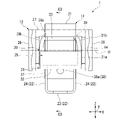
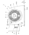
- FIG. 2 is a side view of the anti-vibration device of FIG. 1 as seen from a second direction;
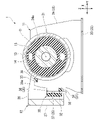
- FIG. 3 is a cross-sectional view taken along line III-III of FIG. 2;
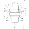
- FIG. 5 is a side view of the anti-vibration device of FIG. 4 as seen from a second direction;
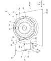
- FIG. 6 is a cross-sectional view taken along the line VI-VI of FIG. 5;
- the vibration isolator 1 includes a first mounting member 11 attached to one of the vibration generating portion and the vibration receiving portion, and a second mounting member 12 attached to the other of the vibration generating portion and the vibration receiving portion. , the outer cylinder 13 attached to the first mounting member 11, the inner cylinder 14 attached to the second mounting member 12 and inserted inside the outer cylinder 13, the inner peripheral surface of the outer cylinder 13 and the inner cylinder and an elastic body 15 in which the outer peripheral surfaces of 14 are connected to each other.
- the anti-vibration device 1 is mounted on, for example, an automobile, and suppresses transmission of engine vibrations to the vehicle body.
- the second mounting member 12 is mounted on the engine (not shown) as a vibration generator
- the first mounting member 11 is mounted on the vehicle body as a vibration receiving section.
- the first mounting member 11 may be mounted on the vibration generating portion
- the second mounting member 12 may be mounted on the vibration receiving portion.
- the first mounting member 11 includes a mounting tube 21 and a base portion 22.
- the pedestal portion 22 includes a seat plate portion 23 and two support plate portions 24 .
- the seat plate portion 23 is fixed to one of the vibration generating portion and the vibration receiving portion.
- the support plate portion 24 protrudes from the seat plate portion 23 .
- the two support plate portions 24 are arranged so that the front and back surfaces face each other.
- the direction in which the support plate portion 24 protrudes from the seat plate portion 23 will be referred to as upward, and the opposite direction will be referred to as downward.
- a direction in which the two support plate portions 24 face each other is called a first direction X. As shown in FIG.
- a mounting hole 24a that opens upward is formed in the support plate portion 24 .
- the mounting hole 24a penetrates the support plate portion 24 in the first direction X.
- the mounting cylinder 21 is fitted and fixed in the mounting hole 24a.
- the mounting cylinder 21 is joined to the support plate portion 24 .
- the mounting cylinder 21 connects the two support plate portions 24 in the first direction X.
- the upper end portion of the mounting cylinder 21 protrudes upward from the upper end edge of the support plate portion 24 .
- the outer cylinder 13 is fitted and fixed inside the mounting cylinder 21 .
- the outer cylinder 13 and the inner cylinder 14 are arranged coaxially with the common axis O.
- the common axis O extends in the first direction X. Note that the common axis O may extend in a direction intersecting with the first direction X. Both ends of the inner cylinder 14 in the first direction X protrude from the outer cylinder 13 in the first direction X respectively.
- the second mounting member 12 includes a pair of first wall portions 26 that cover the first mounting member 11 from both sides in the first direction X, connects the pair of first wall portions 26 to each other, and attaches the first mounting member 11 to each other. and a second wall portion 27 covering in a second direction Y intersecting the first direction X.
- the pair of first wall portions 26 are separately connected to both ends of the inner cylinder 14 in the first direction X. As shown in FIG.
- the second wall portion 27 is separated in the second direction Y from the support plate portion 24 .
- the second wall portion 27 connects the ends in the second direction Y of the pair of first wall portions 26 .
- the second direction Y is orthogonal to the first direction X and the vertical direction.
- the vertical direction will be referred to as a third direction Z hereinafter.
- An elastic stopper 30 is provided between the first mounting member 11 and the second mounting member 12 .
- the elastic stopper 30 has a first stopper portion 31 and a second stopper portion 32 .
- the first stopper portion 31 has a pair of stopper walls 31 a separately provided between the pair of first wall portions 26 and the first mounting member 11 .
- the front and back surfaces of the stopper wall 31a face the first direction X.
- the first stopper portion 31 has a column portion 31b projecting upward from the stopper wall 31a.
- the pair of stopper walls 31a are connected in the first direction X by a second stopper portion 32 and a connecting portion 33 extending in the first direction X. As shown in FIG.
- the second stopper portion 32 is provided between the second wall portion 27 and the first mounting member 11 .
- the second stopper portion 32 is formed in a plate shape, and front and back surfaces of the second stopper portion 32 face the second direction Y.
- the connecting portion 33 is provided away from the second stopper portion 32 in a third direction Z intersecting the first direction X and the second direction Y.
- the connecting portion 33 connects the upper end portions of the column portion 31b of the first stopper portion 31 in the first direction X.
- the column portion 31b is a portion of the first stopper portion 31 that is connected to the connecting portion 33 .
- the first stopper portion 31 includes a bridging wall 34 that connects the pair of stopper walls 31a in the first direction X, as shown in FIG.
- the bridging wall 34 connects the lower ends of the pair of stopper walls 31a in the first direction X.
- the bridging wall 34 is also connected to the lower end portion of the second stopper portion 32 .
- the bridging wall 34 is in contact with or close to the support plate portion 24 of the first mounting member 11 in the second direction Y.
- the bridging wall 34 is formed in a plate shape with front and back surfaces facing the third direction Z.
- the first stopper portion 31, the second stopper portion 32, and the connecting portion 33 are integrally formed of, for example, a rubber material.
- At least one of the first stopper portion 31 and the second stopper portion 32 and the connecting portion 33 are engaged with the first mounting member 11, and the first stopper portion 31 and the connecting portion are engaged.
- a pair of restricting portions that restrict the portions 33 from approaching each other in the third direction Z are provided.
- a column portion 31b of the first stopper portion 31 is pulled in the third direction Z by a pair of restricting portions.
- the first restricting portion 35 locks at least one of the first stopper portion 31 and the second stopper portion 32 .
- the first restricting portion 35 connects the two support plate portions 24 in the first direction X. As shown in FIG.
- the first restricting portion 35 is positioned below the common axis O. As shown in FIG.
- the first restricting portion 35 separates a pair of third wall portions 36 protruding from the two support plate portions 24 to the opposite side of the mounting hole 24a along the second direction Y, and the pair of third wall portions 36 to each other. and a fourth wall portion 37 connected in the first direction X.
- the side away from the common axis O along the second direction Y when viewed from the first direction X is referred to as the outside of the second direction Y, and along the second direction Y when viewed from the first direction X,
- the side closer to the common axis O is called the inner side in the second direction Y.
- the front and back surfaces of the third wall portion 36 face the first direction X. Of the front and back surfaces of each of the pair of third wall portions 36, the opposite surfaces opposite to the surfaces facing each other are covered in the first direction X by the stopper wall 31a over the entire area. The opposite surface of the third wall portion 36 is in contact with or close to the stopper wall 31a.
- a column portion 31b is provided at an inner end portion in the second direction Y of the stopper wall 31a.
- the front and back surfaces of the fourth wall portion 37 face the second direction Y.
- the fourth wall portion 37 connects outer ends in the second direction Y of the third wall portion 36 .
- the fourth wall portion 37 is spaced outward in the second direction Y from the support plate portion 24 .
- the surface facing the outside in the second direction Y is covered in the second direction Y by the second stopper portion 32 over the entire area.
- the surface facing outward in the second direction Y is in contact with or close to the second stopper portion 32 .
- the second stopper portion 32 connects outer ends in the second direction Y of the pair of stopper walls 31a.
- each of the third wall portion 36 and the fourth wall portion 37 is in contact with or close to the upper surface of the bridging wall 34 .
- the first restricting portion 35 locks both the first stopper portion 31 and the second stopper portion 32 and restricts upward movement of the first stopper portion 31 and the second stopper portion 32 .
- the second restricting portion 39 locks the connecting portion 33 .
- the second restricting portion 39 is part of the upper edge of the support plate portion 24 .
- the second restricting portion 39 is positioned above the common axis O. As shown in FIG.
- the lower surface of the connecting portion 33 is hooked on the upper edge of the support plate portion 24 . Thereby, the second restricting portion 39 locks the connecting portion 33 and restricts downward movement of the connecting portion 33 .
- the second restricting portion 39 has a locking projection 39a projecting upward from the upper edge of the support plate portion 24. As shown in FIG. Note that the second restricting portion 39 may not have the locking projection 39a.
- the locking projection 39a is spaced outward in the second direction Y from the mounting hole 24a formed in the support plate portion 24. As shown in FIG. A gap in the second direction Y is provided between the locking projection 39 a and the outer peripheral surface of the mounting cylinder 21 .
- the connecting portion 33 is inserted into this gap, and the connecting portion 33 is in contact with or close to the locking projection 39 a and the outer peripheral surface of the mounting cylinder 21 . Thereby, the second restricting portion 39 restricts the movement of the connecting portion 33 in the direction away from the first mounting member 11 in the second direction Y (outside of the second direction Y).
- the first restricting portion 35 has a snap-fit protrusion 38 that protrudes in the third direction Z and penetrates in the third direction Z through at least one of the first stopper portion 31 and the second stopper portion 32 .
- the tip protruding in the third direction Z from at least one of the first stopper portion 31 and the second stopper portion 32 is at least one of the first stopper portion 31 and the second stopper portion 32. It is locked in the third direction Z with respect to one side.
- the snap-fit protrusion 38 protrudes downward from the lower edge of the fourth wall portion 37 and penetrates the bridging wall 34 of the first stopper portion 31 in the third direction Z.
- the snap-fit projection 38 may penetrate the second stopper portion 32 in the third direction Z.
- An overhanging projection 38 a that overhangs in the first direction X is formed at the tip of the snap-fit projection 38 that projects downward from the bridging wall 34 .
- the protruding protrusion 38 a is in contact with or close to the lower surface of the bridge wall 34 .
- the projecting projection 38a may be formed at the tip of the snap-fit projection 38 so as to project in the second direction Y or the like.
- the snap-fit projection 38 since the snap-fit projection 38 penetrates the bridging wall 34 in the third direction Z, the snap-fit projection 38 contacts the inner surface of the through hole formed in the bridging wall 34 in the second direction Y, Or they will come close to each other. Therefore, the first restricting portion 35 contacts or approaches at least one of the first stopper portion 31 and the second stopper portion 32 in the second direction Y, and the first stopper portion 31 and the second stopper portion 32 are in contact with each other. Movement of at least one of them in the direction away from the first mounting member 11 in the second direction Y (outside of the second direction Y) is restricted.
- the elastic stopper 30 includes the first stopper portion 31 and the second stopper portion 32 . Therefore, when vibrations in the first direction X and the second direction Y are respectively input to the vibration isolator 1, the elastic stopper 30 can collide with the second mounting member 12, and one elastic stopper 30 can It can correspond to a plurality of vibration input directions.
- At least one of the first stopper portion 31 and the second stopper portion 32 and the connecting portion 33 are locked to the first mounting member 11 , and the first stopper portion 31 and the connecting portion 33 extend in the third direction Z
- a first restricting portion 35 and a second restricting portion 39 are provided to restrict the approach of the first stopper portion 31 and the column portion 31b of the first stopper portion 31 in the third direction Z.
- FIG. Therefore, it is possible to fasten the elastic stopper 30 to the first mounting member 11 in the third direction Z, and even if the elastic stopper 30 is not adhered to the first mounting member 11, for example, when assembling to a vehicle or the like. , the positional displacement of the elastic stopper 30 with respect to the first mounting member 11 can be suppressed. Since the first stopper portion 31, the second stopper portion 32, and the connecting portion 33 are integrally formed, an increase in the number of parts can be prevented.
- the first restricting portion 35 contacts or approaches at least one of the first stopper portion 31 and the second stopper portion 32 in the second direction Y
- the second restricting portion 39 contacts the connecting portion 33 in the second direction. Abut or approach in two directions Y.
- the first restricting portion 35 and the second restricting portion 39 separate at least one of the first stopper portion 31 and the second stopper portion 32 and the connecting portion 33 from the first mounting member 11 in the second direction Y. Regulates directional movement. Therefore, it is possible to prevent the elastic stopper 30 from coming off in the second direction Y from the first mounting member 11 .
- the elastic stopper 30 can be made compact.
- the first restricting portion 35 penetrates at least one of the first stopper portion 31 and the second stopper portion 32 in the third direction Z, and extends to at least one of the first stopper portion 31 and the second stopper portion 32.
- it has a snap-fit projection 38 that is locked in the third direction Z. As shown in FIG. Therefore, at least one of the first stopper portion 31 and the second stopper portion 32 can be reliably prevented from being displaced in the second direction Y with respect to the first mounting member 11 .
- the snap-fit projection 38 does not It is possible to suppress slipping in the third direction Z from at least one of the stopper portions 32 .
- FIG. 1 a vibration isolator 2 according to a second embodiment of the invention will be described with reference to FIGS. 4 to 6.
- FIG. 1 the same reference numerals are assigned to the same components as in the first embodiment, the description thereof is omitted, and only the different points will be described.
- the first restricting portion 35 does not have the snap-fit projection 38 , and the bridging wall 34 is spaced inward in the second direction Y from the second stopper portion 32 .
- Lower ends of the third wall portion 36 and the fourth wall portion 37 of the first restricting portion 35 protrude downward from the stopper wall 31a and the second stopper portion 32, respectively.
- the third wall portion 36 of the first restricting portion 35 is formed with a locking recessed portion 39b that opens inwardly and downwardly in the second direction Y.
- the locking recess 39b penetrates the third wall portion 36 in the first direction X.
- the locking recess 39b is formed at the lower end of the third wall portion 36.
- a bridging wall 34 is inserted into the locking recess 39b.
- the bridging wall 34 is sandwiched in the second direction Y by the inner surface of the locking recess 39b and the support plate portion 24, and is in contact with or close to the inner surface of the locking recess 39b and the support plate portion 24. .
- the first restricting portion 35 restricts the movement of the first stopper portion 31 in the second direction Y away from the first mounting member 11 .
- the upper surface of the bridging wall 34 abuts on or is close to the upper end surface of the inner surface of the locking recess 39b that is located at the upper end and faces downward. Thereby, the first restricting portion 35 locks the first stopper portion 31 and restricts upward movement of the first stopper portion 31 .
- the vibration isolator 2 As described above, according to the vibration isolator 2 according to the present embodiment, as in the above embodiment, it is possible to suppress an increase in the number of parts, and it is possible to correspond to a plurality of input directions of vibration, and an adhesive is used. Even without it, it is possible to prevent the elastic stopper 30 from being displaced with respect to the first mounting member 11 . Further, a locking recess 39b is formed in the third wall portion 36 of the first restricting portion 35, a bridging wall 34 is inserted into the locking recess 39b, and an upper surface of the bridging wall 34 is formed on the upper end surface of the locking recess 39b. are in contact with or close to each other. Therefore, the state in which the column portion 31b of the first stopper portion 31 is strongly pulled in the third direction Z by the first restricting portion 35 and the second restricting portion 39 can be reliably maintained.
- the first stopper portion 31 may not have the bridging wall 34 .
- the first restricting portion 35 and at least one of the first stopper portion 31 and the second stopper portion 32 are provided with an uneven portion or the like that engages with each other, so that the first restricting portion 35 is aligned with the first stopper portion.
- a configuration in which at least one of 31 and second stopper portion 32 is locked may be adopted.
- the elastic stopper includes the first stopper portion and the second stopper portion. Therefore, when vibrations in the first direction and the second direction are respectively input to the vibration isolator, the elastic stopper can collide with the second mounting member. can correspond to At least one of the first stopper portion and the second stopper portion and the connecting portion are locked to the first mounting member, and the first stopper portion and the connecting portion are restricted from approaching each other in the third direction. A pair of regulating portions are provided, and a connecting portion of the first stopper portion to the connecting portion is pulled in the third direction.
- the elastic stopper can be fastened to the first mounting member in the third direction, and even if the elastic stopper is not adhered to the first mounting member, the elastic stopper can be attached to the first mounting member, for example, during assembly to a vehicle or the like. It is possible to suppress positional displacement with respect to the mounting member. Since the first stopper portion, the second stopper portion, and the connecting portion are integrally formed, an increase in the number of parts can be prevented.
- the first restricting portion of the pair of restricting portions is attached to at least one of the first stopper portion and the second stopper portion. , abutting or approaching in the second direction, wherein the second restricting portion of the pair of restricting portions abuts or approaches the connecting portion in the second direction, and the pair of restricting portions are At least one of the first stopper portion and the second stopper portion and the connecting portion are restricted from moving away from the first mounting member in the second direction.
- the first restricting portion abuts or approaches at least one of the first stopper portion and the second stopper portion in the second direction
- the second restricting portion Abutting or approaching in two directions the first restricting portion and the second restricting portion are connected to at least one of the first stopper portion and the second stopper portion and the connecting portion from the first mounting member to the second stopper portion. Regulate movement away from the direction. Therefore, it is possible to prevent the elastic stopper from coming off the first mounting member in the second direction.
- the second stopper portion connects the ends of the pair of stopper walls in the second direction.
- the second stopper portion connects the ends of the pair of stopper walls in the second direction, so that the elastic stopper can be made compact.
- a vibration isolator is any one of the first to third aspects, wherein one of the pair of restricting portions protrudes in the third direction.
- a snap-fit projection penetrating at least one of the first stopper portion and the second stopper portion in the third direction, wherein the snap-fit projection includes one of the first stopper portion and the second stopper portion A tip portion protruding in the third direction from at least one of is locked in the third direction with respect to at least one of the first stopper portion and the second stopper portion.
- one of the pair of restricting portions penetrates at least one of the first stopper portion and the second stopper portion in the third direction, At least one of the two stopper portions is provided with a snap-fit projection locked in the third direction. Therefore, it is possible to reliably prevent at least one of the first stopper portion and the second stopper portion from being displaced in the second direction with respect to the first mounting member. Further, even if the connecting portion of the first stopper portion is strongly pulled in the third direction by the pair of restricting portions, the snap-fit protrusions are prevented from moving in the third direction from at least one of the first stopper portion and the second stopper portion. can be suppressed.
- the vibration isolator it is possible to correspond to a plurality of input directions of vibration while suppressing an increase in the number of parts, and the elastic stopper can be attached to the first mounting member without bonding. It is possible to prevent positional deviation.
Landscapes
- Engineering & Computer Science (AREA)
- General Engineering & Computer Science (AREA)
- Mechanical Engineering (AREA)
- Manufacturing & Machinery (AREA)
- Health & Medical Sciences (AREA)
- Child & Adolescent Psychology (AREA)
- Vibration Prevention Devices (AREA)
- Springs (AREA)
- Physics & Mathematics (AREA)
- Acoustics & Sound (AREA)
- Aviation & Aerospace Engineering (AREA)
Abstract
Description
本願は、2021年5月11日に、日本に出願された特願2021-080333号に基づき優先権を主張し、その内容をここに援用する。
また、部品点数を増大させずに、一対の第1壁部が互いに対向する第1方向とは異なる他の方向に対応したストッパ部を追加して設けることが困難である。
防振装置1は、振動発生部および振動受部のうちのいずれか一方に取付けられる第1取付部材11、および振動発生部および振動受部のうちのいずれか他方に取付けられる第2取付部材12と、第1取付部材11に取付けられた外筒13、および第2取付部材12に取付けられ、かつ外筒13の内側に挿入された内筒14と、外筒13の内周面および内筒14の外周面を互いに連結した弾性体15と、を備えている。
座板部23は、振動発生部および振動受部のうちのいずれか一方に固定される。支持板部24は、座板部23から突出している。2つの支持板部24は、表裏面が互いに対向する向きに並べられている。
以下、支持板部24が座板部23から突出している向きを上方といい、これとは逆向きを下方という。2つの支持板部24が互いに対向している方向を第1方向Xという。
第2壁部27は、支持板部24から第2方向Yに離れている。第2壁部27は、一対の第1壁部26における第2方向Yの端部同士を連結している。第2方向Yは、第1方向Xおよび上下方向に直交している。
以下、上下方向を第3方向Zという。
連結部33は、第2ストッパ部32から、第1方向Xおよび第2方向Yに交差する第3方向Zに離れて設けられている。連結部33は、第1ストッパ部31の柱部31bにおける上端部同士を第1方向Xに連結している。柱部31bが、第1ストッパ部31における連結部33との接続部分となっている。
第1ストッパ部31、第2ストッパ部32、および連結部33は、例えばゴム材料等で一体に形成されている。
第1規制部35は、共通軸Oより下方に位置している。第1規制部35は、2つの支持板部24から各別に、第2方向Yに沿う装着孔24aの反対側に突出する一対の第3壁部36と、一対の第3壁部36同士を第1方向Xに連結する第4壁部37と、を備えている。
スナップフィット突起38のうち、架橋壁34から下方に突出した先端部に、第1方向Xに張り出した張出突起38aが形成されている。張出突起38aは、架橋壁34の下面に当接、若しくは近接している。なお、張出突起38aは、スナップフィット突起38の先端部に、第2方向Y等に張り出して形成されてもよい。
したがって、第1規制部35は、第1ストッパ部31および第2ストッパ部32のうちの少なくとも一方に、第2方向Yに当接、若しくは近接し、第1ストッパ部31および第2ストッパ部32のうちの少なくとも一方の、第1取付部材11から第2方向Yに離れる向き(第2方向Yの外側)の移動を規制する。
したがって、弾性ストッパ30を、第1取付部材11に、第3方向Zに締め付けることが可能になり、弾性ストッパ30を第1取付部材11に接着しなくても、例えば車両等への組付け時に、弾性ストッパ30が第1取付部材11に対して位置ずれするのを抑えることができる。
第1ストッパ部31、第2ストッパ部32、および連結部33が、一体に形成されているので、部品点数の増大を防ぐことができる。
したがって、第1ストッパ部31および第2ストッパ部32のうちの少なくとも一方が、第1取付部材11に対して第2方向Yに位置ずれするのを確実に抑制することができる。また、第1規制部35および第2規制部39によって、第1ストッパ部31の柱部31bを第3方向Zに強く引張しても、スナップフィット突起38が、第1ストッパ部31および第2ストッパ部32のうちの少なくとも一方から第3方向Zに抜けるのを抑制することができる。
なお、この第2実施形態においては、第1実施形態における構成要素と同一の部分については同一の符号を付し、その説明を省略し、異なる点についてのみ説明する。
第1規制部35の第3壁部36に、第2方向Yの内側および下方に開口した係止凹部39bが形成されている。係止凹部39bは、第3壁部36を第1方向Xに貫く。係止凹部39bは、第3壁部36の下端部に形成されている。係止凹部39bに、架橋壁34が挿入されている。
係止凹部39bの内面のうち、上端に位置して下方を向く上端面に、架橋壁34の上面が当接、若しくは近接している。これにより、第1規制部35は、第1ストッパ部31を係止し、第1ストッパ部31の上方に向けた移動を規制する。
さらに、第1規制部35の第3壁部36に、係止凹部39bが形成され、係止凹部39bに、架橋壁34が挿入され、係止凹部39bの上端面に、架橋壁34の上面が当接、若しくは近接している。したがって、第1ストッパ部31の柱部31bを、第1規制部35および第2規制部39によって第3方向Zに強く引張した状態を確実に維持することができる。
第1規制部35と、第1ストッパ部31および第2ストッパ部32のうちの少なくとも一方と、に、互いに係合する凹凸部等を設けることにより、第1規制部35が、第1ストッパ部31および第2ストッパ部32のうちの少なくとも一方を係止する構成を採用してもよい。
第1取付部材に、第1ストッパ部および第2ストッパ部のうちの少なくとも一方と、連結部と、を係止し、第1ストッパ部および連結部が、第3方向に互いに接近することを規制する一対の規制部が設けられ、第1ストッパ部における連結部との接続部分が、第3方向に引張されている。したがって、弾性ストッパを、第1取付部材に第3方向に締め付けることが可能になり、弾性ストッパを第1取付部材に接着しなくても、例えば車両等への組付け時に、弾性ストッパが第1取付部材に対して位置ずれするのを抑えることができる。
第1ストッパ部、第2ストッパ部、および連結部が、一体に形成されているので、部品点数の増大を防ぐことができる。
11 第1取付部材
12 第2取付部材
13 外筒
14 内筒
15 弾性体
26 第1壁部
27 第2壁部
30 弾性ストッパ
31 第1ストッパ部
31a ストッパ壁
32 第2ストッパ部
33 連結部
35 第1規制部(規制部)
38 スナップフィット突起
39 第2規制部(規制部)
X 第1方向
Y 第2方向
Z 第3方向
Claims (4)
- 振動発生部および振動受部のうちのいずれか一方に取付けられる第1取付部材、および振動発生部および振動受部のうちのいずれか他方に取付けられる第2取付部材と、
前記第1取付部材に取付けられた外筒と、
前記第2取付部材に取付けられ、かつ前記外筒の内側に挿入された内筒と、
前記外筒の内周面および前記内筒の外周面を互いに連結した弾性体と、
前記第1取付部材と前記第2取付部材との間に設けられる弾性ストッパと、
を備え、
前記第2取付部材は、前記第1取付部材を、第1方向の両側から覆う一対の第1壁部と、一対の前記第1壁部同士を連結し、かつ前記第1取付部材を前記第1方向に交差する第2方向に覆う第2壁部と、を備え、
前記弾性ストッパは、
一対の前記第1壁部と前記第1取付部材との間に各別に設けられた一対のストッパ壁を有する第1ストッパ部と、
前記第2壁部と前記第1取付部材との間に設けられた第2ストッパ部と、を備え、
一対の前記ストッパ壁は、前記第2ストッパ部と、前記第1方向に延びる連結部と、により、前記第1方向に連結され、
前記連結部は、前記第2ストッパ部から前記第1方向および前記第2方向に交差する第3方向に離れて設けられ、
前記第1ストッパ部、前記第2ストッパ部、および前記連結部は、一体に形成され、
前記第1取付部材には、前記第1ストッパ部および前記第2ストッパ部のうちの少なくとも一方と、前記連結部と、を係止し、前記第1ストッパ部および前記連結部が、前記第3方向に互いに接近することを規制する一対の規制部が設けられ、
前記第1ストッパ部における前記連結部との接続部分が、前記第3方向に引張されている、防振装置。 - 一対の前記規制部のうち第1規制部は、前記第1ストッパ部および前記第2ストッパ部のうちの少なくとも一方に、前記第2方向に当接、若しくは近接し、一対の前記規制部のうち第2規制部は、前記連結部に、前記第2方向に当接、若しくは近接し、一対の前記規制部は、前記第1ストッパ部および前記第2ストッパ部のうちの少なくとも一方と、前記連結部と、の、前記第1取付部材から前記第2方向に離れる向きの移動を規制する、請求項1に記載の防振装置。
- 前記第2ストッパ部は、一対の前記ストッパ壁における前記第2方向の端部同士を連結している、請求項1または2に記載の防振装置。
- 一対の前記規制部のうちのいずれか一方の前記規制部は、前記第3方向に突出し、前記第1ストッパ部および前記第2ストッパ部のうちの少なくとも一方を、前記第3方向に貫くスナップフィット突起を備え、
前記スナップフィット突起において、前記第1ストッパ部および前記第2ストッパ部のうちの少なくとも一方から、前記第3方向に突出した先端部は、前記第1ストッパ部および前記第2ストッパ部のうちの少なくとも一方に対して、前記第3方向に係止されている、
請求項1から3のいずれか1項に記載の防振装置。
Priority Applications (3)
| Application Number | Priority Date | Filing Date | Title |
|---|---|---|---|
| CN202280034283.4A CN117321316B (zh) | 2021-05-11 | 2022-01-18 | 隔振装置 |
| EP22807009.0A EP4339480A4 (en) | 2021-05-11 | 2022-01-18 | Vibration isolation device |
| US18/559,566 US12590617B2 (en) | 2021-05-11 | 2022-01-18 | Vibration isolation device |
Applications Claiming Priority (2)
| Application Number | Priority Date | Filing Date | Title |
|---|---|---|---|
| JP2021-080333 | 2021-05-11 | ||
| JP2021080333A JP7536707B2 (ja) | 2021-05-11 | 2021-05-11 | 防振装置 |
Publications (1)
| Publication Number | Publication Date |
|---|---|
| WO2022239302A1 true WO2022239302A1 (ja) | 2022-11-17 |
Family
ID=84028128
Family Applications (1)
| Application Number | Title | Priority Date | Filing Date |
|---|---|---|---|
| PCT/JP2022/001604 Ceased WO2022239302A1 (ja) | 2021-05-11 | 2022-01-18 | 防振装置 |
Country Status (5)
| Country | Link |
|---|---|
| US (1) | US12590617B2 (ja) |
| EP (1) | EP4339480A4 (ja) |
| JP (1) | JP7536707B2 (ja) |
| CN (1) | CN117321316B (ja) |
| WO (1) | WO2022239302A1 (ja) |
Families Citing this family (1)
| Publication number | Priority date | Publication date | Assignee | Title |
|---|---|---|---|---|
| JP2026058116A (ja) * | 2024-09-24 | 2026-04-03 | 株式会社プロスパイラ | 防振装置 |
Citations (6)
| Publication number | Priority date | Publication date | Assignee | Title |
|---|---|---|---|---|
| JPH0694062A (ja) * | 1992-09-09 | 1994-04-05 | Nissan Motor Co Ltd | 防振支持装置用ストッパ |
| JPH07158696A (ja) * | 1993-12-07 | 1995-06-20 | Kinugawa Rubber Ind Co Ltd | エンジンマウント取付用ストッパ |
| JP2008248947A (ja) * | 2007-03-29 | 2008-10-16 | Tokai Rubber Ind Ltd | 筒型防振装置およびそれに用いられるストッパゴム |
| JP2014066334A (ja) | 2012-09-27 | 2014-04-17 | Tokai Rubber Ind Ltd | ストッパゴム付き防振装置 |
| JP2020180690A (ja) * | 2019-04-26 | 2020-11-05 | 株式会社ブリヂストン | 防振装置用ストッパー |
| JP2021080333A (ja) | 2019-11-15 | 2021-05-27 | 信越化学工業株式会社 | ポリエーテル変性シロキサン、塗料添加剤、塗料組成物、コーティング剤、コーティング層、及びポリエーテル変性シロキサンの製造方法 |
Family Cites Families (18)
| Publication number | Priority date | Publication date | Assignee | Title |
|---|---|---|---|---|
| US5295653A (en) * | 1991-10-11 | 1994-03-22 | Toyoda Gosei Co., Ltd. | Vibration insulator having bracket |
| US5718407A (en) * | 1995-09-14 | 1998-02-17 | Hyundai Motor Company | Power unit mounting system |
| JP4018256B2 (ja) * | 1998-09-04 | 2007-12-05 | 山下ゴム株式会社 | 円筒型液封防振装置 |
| FR2815579B1 (fr) * | 2000-10-23 | 2003-01-31 | Peugeot Citroen Automobiles Sa | Suspension de vehicule automobile |
| KR100499774B1 (ko) * | 2002-08-16 | 2005-07-07 | 현대모비스 주식회사 | 엔진 지지구조 |
| JP2005315315A (ja) * | 2004-04-28 | 2005-11-10 | Tokai Rubber Ind Ltd | トルクロッド |
| WO2008043695A1 (de) * | 2006-10-10 | 2008-04-17 | Trelleborg Automotive Technical Centre Gmbh | Verfahren zum kalibrieren einer elastomerfeder eines lagers sowie nach diesem verfahren hergestelltes lager |
| JP4722883B2 (ja) * | 2007-06-20 | 2011-07-13 | 山下ゴム株式会社 | トルクロッド |
| JP4755147B2 (ja) * | 2007-07-03 | 2011-08-24 | 東洋ゴム工業株式会社 | 防振装置 |
| US20090315235A1 (en) * | 2008-06-20 | 2009-12-24 | The Pullman Company | Axial shear-leg isolator |
| JP2012097878A (ja) * | 2010-11-05 | 2012-05-24 | Kurashiki Kako Co Ltd | 防振連結ロッド |
| US20130134641A1 (en) * | 2011-11-29 | 2013-05-30 | Kurashiki Kako Co., Ltd. | Vibration isolator |
| FR3017913B1 (fr) * | 2014-02-27 | 2016-02-26 | Hutchinson | Bielle antivibratoire |
| JP6436786B2 (ja) * | 2015-01-13 | 2018-12-12 | 山下ゴム株式会社 | マウント装置 |
| JP7154067B2 (ja) * | 2018-08-31 | 2022-10-17 | Toyo Tire株式会社 | ストッパ及び防振ユニット |
| DE102018132558A1 (de) * | 2018-12-17 | 2020-06-18 | Bayerische Motoren Werke Aktiengesellschaft | Elastomerlager zur Anbringung eines Aggregats im Fahrzeug |
| JP7329429B2 (ja) * | 2019-12-05 | 2023-08-18 | 住友理工株式会社 | ブラケット付き筒型防振装置 |
| JP7772653B2 (ja) * | 2022-05-17 | 2025-11-18 | 住友理工株式会社 | 防振装置 |
-
2021
- 2021-05-11 JP JP2021080333A patent/JP7536707B2/ja active Active
-
2022
- 2022-01-18 EP EP22807009.0A patent/EP4339480A4/en active Pending
- 2022-01-18 CN CN202280034283.4A patent/CN117321316B/zh active Active
- 2022-01-18 WO PCT/JP2022/001604 patent/WO2022239302A1/ja not_active Ceased
- 2022-01-18 US US18/559,566 patent/US12590617B2/en active Active
Patent Citations (6)
| Publication number | Priority date | Publication date | Assignee | Title |
|---|---|---|---|---|
| JPH0694062A (ja) * | 1992-09-09 | 1994-04-05 | Nissan Motor Co Ltd | 防振支持装置用ストッパ |
| JPH07158696A (ja) * | 1993-12-07 | 1995-06-20 | Kinugawa Rubber Ind Co Ltd | エンジンマウント取付用ストッパ |
| JP2008248947A (ja) * | 2007-03-29 | 2008-10-16 | Tokai Rubber Ind Ltd | 筒型防振装置およびそれに用いられるストッパゴム |
| JP2014066334A (ja) | 2012-09-27 | 2014-04-17 | Tokai Rubber Ind Ltd | ストッパゴム付き防振装置 |
| JP2020180690A (ja) * | 2019-04-26 | 2020-11-05 | 株式会社ブリヂストン | 防振装置用ストッパー |
| JP2021080333A (ja) | 2019-11-15 | 2021-05-27 | 信越化学工業株式会社 | ポリエーテル変性シロキサン、塗料添加剤、塗料組成物、コーティング剤、コーティング層、及びポリエーテル変性シロキサンの製造方法 |
Non-Patent Citations (1)
| Title |
|---|
| See also references of EP4339480A4 |
Also Published As
| Publication number | Publication date |
|---|---|
| EP4339480A1 (en) | 2024-03-20 |
| EP4339480A4 (en) | 2025-05-07 |
| JP2022174497A (ja) | 2022-11-24 |
| CN117321316A (zh) | 2023-12-29 |
| US20240229895A1 (en) | 2024-07-11 |
| CN117321316B (zh) | 2026-04-24 |
| JP7536707B2 (ja) | 2024-08-20 |
| US12590617B2 (en) | 2026-03-31 |
Similar Documents
| Publication | Publication Date | Title |
|---|---|---|
| JP6813998B2 (ja) | 防振装置 | |
| EP3203108B1 (en) | Vibration isolation device | |
| CN112262267B (zh) | 带托架的防振装置 | |
| US20170299013A1 (en) | Vibration isolation device | |
| CN108025632B (zh) | 发动机悬置构造 | |
| CN107131249A (zh) | 防振装置 | |
| JP7536707B2 (ja) | 防振装置 | |
| CN112771285A (zh) | 带托架的防振装置 | |
| CN112922988B (zh) | 带托架的筒型防振装置 | |
| JP6410577B2 (ja) | 防振装置用ブラケットおよび防振装置 | |
| JP4287462B2 (ja) | 防振装置 | |
| US20220260131A1 (en) | Vibration proofing device and bracket | |
| US20220403903A1 (en) | Vibration damper | |
| JP4317209B2 (ja) | 防振装置 | |
| US12104670B2 (en) | Vibration-damping device | |
| US7445401B2 (en) | Connecting element for releasably and vibration damping connection of a first component to a second component | |
| JP2006097741A (ja) | エンジンマウント | |
| JP2008249032A (ja) | 防振装置 | |
| JP2005036762A (ja) | ポンプの取付部材および取付構造 | |
| JP2007120672A (ja) | 防振マウント | |
| JP2024122235A (ja) | 取付構造 | |
| WO2025084047A1 (ja) | 車載カバー | |
| JP2021076231A (ja) | 防振装置 | |
| JP2010042787A (ja) | 車両用サンバイザ | |
| JP2007177817A (ja) | 防振装置及び筒状金具 |
Legal Events
| Date | Code | Title | Description |
|---|---|---|---|
| 121 | Ep: the epo has been informed by wipo that ep was designated in this application |
Ref document number: 22807009 Country of ref document: EP Kind code of ref document: A1 |
|
| WWE | Wipo information: entry into national phase |
Ref document number: 18559566 Country of ref document: US |
|
| WWE | Wipo information: entry into national phase |
Ref document number: 202280034283.4 Country of ref document: CN |
|
| WWE | Wipo information: entry into national phase |
Ref document number: 2022807009 Country of ref document: EP |
|
| NENP | Non-entry into the national phase |
Ref country code: DE |
|
| ENP | Entry into the national phase |
Ref document number: 2022807009 Country of ref document: EP Effective date: 20231211 |
|
| WWG | Wipo information: grant in national office |
Ref document number: 18559566 Country of ref document: US |