WO2022239731A1 - ホットスタンプ用鋼板およびホットスタンプ成形体 - Google Patents
ホットスタンプ用鋼板およびホットスタンプ成形体 Download PDFInfo
- Publication number
- WO2022239731A1 WO2022239731A1 PCT/JP2022/019656 JP2022019656W WO2022239731A1 WO 2022239731 A1 WO2022239731 A1 WO 2022239731A1 JP 2022019656 W JP2022019656 W JP 2022019656W WO 2022239731 A1 WO2022239731 A1 WO 2022239731A1
- Authority
- WO
- WIPO (PCT)
- Prior art keywords
- less
- hot
- content
- stamped
- prior austenite
- Prior art date
- Legal status (The legal status is an assumption and is not a legal conclusion. Google has not performed a legal analysis and makes no representation as to the accuracy of the status listed.)
- Ceased
Links
Classifications
-
- C—CHEMISTRY; METALLURGY
- C22—METALLURGY; FERROUS OR NON-FERROUS ALLOYS; TREATMENT OF ALLOYS OR NON-FERROUS METALS
- C22C—ALLOYS
- C22C38/00—Ferrous alloys, e.g. steel alloys
- C22C38/02—Ferrous alloys, e.g. steel alloys containing silicon
-
- C—CHEMISTRY; METALLURGY
- C22—METALLURGY; FERROUS OR NON-FERROUS ALLOYS; TREATMENT OF ALLOYS OR NON-FERROUS METALS
- C22C—ALLOYS
- C22C38/00—Ferrous alloys, e.g. steel alloys
- C22C38/18—Ferrous alloys, e.g. steel alloys containing chromium
- C22C38/40—Ferrous alloys, e.g. steel alloys containing chromium with nickel
- C22C38/58—Ferrous alloys, e.g. steel alloys containing chromium with nickel with more than 1.5% by weight of manganese
-
- C—CHEMISTRY; METALLURGY
- C21—METALLURGY OF IRON
- C21D—MODIFYING THE PHYSICAL STRUCTURE OF FERROUS METALS; GENERAL DEVICES FOR HEAT TREATMENT OF FERROUS OR NON-FERROUS METALS OR ALLOYS; MAKING METAL MALLEABLE, e.g. BY DECARBURISATION OR TEMPERING
- C21D1/00—General methods or devices for heat treatment, e.g. annealing, hardening, quenching or tempering
- C21D1/02—Hardening articles or materials formed by forging or rolling, with no further heating beyond that required for the formation
-
- C—CHEMISTRY; METALLURGY
- C21—METALLURGY OF IRON
- C21D—MODIFYING THE PHYSICAL STRUCTURE OF FERROUS METALS; GENERAL DEVICES FOR HEAT TREATMENT OF FERROUS OR NON-FERROUS METALS OR ALLOYS; MAKING METAL MALLEABLE, e.g. BY DECARBURISATION OR TEMPERING
- C21D1/00—General methods or devices for heat treatment, e.g. annealing, hardening, quenching or tempering
- C21D1/18—Hardening; Quenching with or without subsequent tempering
-
- C—CHEMISTRY; METALLURGY
- C21—METALLURGY OF IRON
- C21D—MODIFYING THE PHYSICAL STRUCTURE OF FERROUS METALS; GENERAL DEVICES FOR HEAT TREATMENT OF FERROUS OR NON-FERROUS METALS OR ALLOYS; MAKING METAL MALLEABLE, e.g. BY DECARBURISATION OR TEMPERING
- C21D1/00—General methods or devices for heat treatment, e.g. annealing, hardening, quenching or tempering
- C21D1/62—Quenching devices
- C21D1/673—Quenching devices for die quenching
-
- C—CHEMISTRY; METALLURGY
- C21—METALLURGY OF IRON
- C21D—MODIFYING THE PHYSICAL STRUCTURE OF FERROUS METALS; GENERAL DEVICES FOR HEAT TREATMENT OF FERROUS OR NON-FERROUS METALS OR ALLOYS; MAKING METAL MALLEABLE, e.g. BY DECARBURISATION OR TEMPERING
- C21D7/00—Modifying the physical properties of iron or steel by deformation
- C21D7/13—Modifying the physical properties of iron or steel by deformation by hot working
-
- C—CHEMISTRY; METALLURGY
- C21—METALLURGY OF IRON
- C21D—MODIFYING THE PHYSICAL STRUCTURE OF FERROUS METALS; GENERAL DEVICES FOR HEAT TREATMENT OF FERROUS OR NON-FERROUS METALS OR ALLOYS; MAKING METAL MALLEABLE, e.g. BY DECARBURISATION OR TEMPERING
- C21D8/00—Modifying the physical properties of ferrous metals or ferrous alloys by deformation combined with, or followed by, heat treatment
- C21D8/02—Modifying the physical properties of ferrous metals or ferrous alloys by deformation combined with, or followed by, heat treatment during manufacturing of plates or strips
-
- C—CHEMISTRY; METALLURGY
- C21—METALLURGY OF IRON
- C21D—MODIFYING THE PHYSICAL STRUCTURE OF FERROUS METALS; GENERAL DEVICES FOR HEAT TREATMENT OF FERROUS OR NON-FERROUS METALS OR ALLOYS; MAKING METAL MALLEABLE, e.g. BY DECARBURISATION OR TEMPERING
- C21D8/00—Modifying the physical properties of ferrous metals or ferrous alloys by deformation combined with, or followed by, heat treatment
- C21D8/02—Modifying the physical properties of ferrous metals or ferrous alloys by deformation combined with, or followed by, heat treatment during manufacturing of plates or strips
- C21D8/0221—Modifying the physical properties of ferrous metals or ferrous alloys by deformation combined with, or followed by, heat treatment during manufacturing of plates or strips characterised by the working steps
- C21D8/0226—Hot rolling
-
- C—CHEMISTRY; METALLURGY
- C21—METALLURGY OF IRON
- C21D—MODIFYING THE PHYSICAL STRUCTURE OF FERROUS METALS; GENERAL DEVICES FOR HEAT TREATMENT OF FERROUS OR NON-FERROUS METALS OR ALLOYS; MAKING METAL MALLEABLE, e.g. BY DECARBURISATION OR TEMPERING
- C21D9/00—Heat treatment, e.g. annealing, hardening, quenching or tempering, adapted for particular articles; Furnaces therefor
- C21D9/46—Heat treatment, e.g. annealing, hardening, quenching or tempering, adapted for particular articles; Furnaces therefor for sheet metals
-
- C—CHEMISTRY; METALLURGY
- C22—METALLURGY; FERROUS OR NON-FERROUS ALLOYS; TREATMENT OF ALLOYS OR NON-FERROUS METALS
- C22C—ALLOYS
- C22C38/00—Ferrous alloys, e.g. steel alloys
- C22C38/001—Ferrous alloys, e.g. steel alloys containing N
-
- C—CHEMISTRY; METALLURGY
- C22—METALLURGY; FERROUS OR NON-FERROUS ALLOYS; TREATMENT OF ALLOYS OR NON-FERROUS METALS
- C22C—ALLOYS
- C22C38/00—Ferrous alloys, e.g. steel alloys
- C22C38/005—Ferrous alloys, e.g. steel alloys containing rare earths, i.e. Sc, Y, Lanthanides
-
- C—CHEMISTRY; METALLURGY
- C22—METALLURGY; FERROUS OR NON-FERROUS ALLOYS; TREATMENT OF ALLOYS OR NON-FERROUS METALS
- C22C—ALLOYS
- C22C38/00—Ferrous alloys, e.g. steel alloys
- C22C38/008—Ferrous alloys, e.g. steel alloys containing tin
-
- C—CHEMISTRY; METALLURGY
- C22—METALLURGY; FERROUS OR NON-FERROUS ALLOYS; TREATMENT OF ALLOYS OR NON-FERROUS METALS
- C22C—ALLOYS
- C22C38/00—Ferrous alloys, e.g. steel alloys
- C22C38/04—Ferrous alloys, e.g. steel alloys containing manganese
-
- C—CHEMISTRY; METALLURGY
- C22—METALLURGY; FERROUS OR NON-FERROUS ALLOYS; TREATMENT OF ALLOYS OR NON-FERROUS METALS
- C22C—ALLOYS
- C22C38/00—Ferrous alloys, e.g. steel alloys
- C22C38/06—Ferrous alloys, e.g. steel alloys containing aluminium
-
- C—CHEMISTRY; METALLURGY
- C22—METALLURGY; FERROUS OR NON-FERROUS ALLOYS; TREATMENT OF ALLOYS OR NON-FERROUS METALS
- C22C—ALLOYS
- C22C38/00—Ferrous alloys, e.g. steel alloys
- C22C38/18—Ferrous alloys, e.g. steel alloys containing chromium
- C22C38/22—Ferrous alloys, e.g. steel alloys containing chromium with molybdenum or tungsten
-
- C—CHEMISTRY; METALLURGY
- C22—METALLURGY; FERROUS OR NON-FERROUS ALLOYS; TREATMENT OF ALLOYS OR NON-FERROUS METALS
- C22C—ALLOYS
- C22C38/00—Ferrous alloys, e.g. steel alloys
- C22C38/18—Ferrous alloys, e.g. steel alloys containing chromium
- C22C38/26—Ferrous alloys, e.g. steel alloys containing chromium with niobium or tantalum
-
- C—CHEMISTRY; METALLURGY
- C22—METALLURGY; FERROUS OR NON-FERROUS ALLOYS; TREATMENT OF ALLOYS OR NON-FERROUS METALS
- C22C—ALLOYS
- C22C38/00—Ferrous alloys, e.g. steel alloys
- C22C38/18—Ferrous alloys, e.g. steel alloys containing chromium
- C22C38/28—Ferrous alloys, e.g. steel alloys containing chromium with titanium or zirconium
-
- C—CHEMISTRY; METALLURGY
- C22—METALLURGY; FERROUS OR NON-FERROUS ALLOYS; TREATMENT OF ALLOYS OR NON-FERROUS METALS
- C22C—ALLOYS
- C22C38/00—Ferrous alloys, e.g. steel alloys
- C22C38/18—Ferrous alloys, e.g. steel alloys containing chromium
- C22C38/30—Ferrous alloys, e.g. steel alloys containing chromium with cobalt
-
- C—CHEMISTRY; METALLURGY
- C22—METALLURGY; FERROUS OR NON-FERROUS ALLOYS; TREATMENT OF ALLOYS OR NON-FERROUS METALS
- C22C—ALLOYS
- C22C38/00—Ferrous alloys, e.g. steel alloys
- C22C38/18—Ferrous alloys, e.g. steel alloys containing chromium
- C22C38/32—Ferrous alloys, e.g. steel alloys containing chromium with boron
-
- C—CHEMISTRY; METALLURGY
- C22—METALLURGY; FERROUS OR NON-FERROUS ALLOYS; TREATMENT OF ALLOYS OR NON-FERROUS METALS
- C22C—ALLOYS
- C22C38/00—Ferrous alloys, e.g. steel alloys
- C22C38/18—Ferrous alloys, e.g. steel alloys containing chromium
- C22C38/38—Ferrous alloys, e.g. steel alloys containing chromium with more than 1.5% by weight of manganese
-
- C—CHEMISTRY; METALLURGY
- C22—METALLURGY; FERROUS OR NON-FERROUS ALLOYS; TREATMENT OF ALLOYS OR NON-FERROUS METALS
- C22C—ALLOYS
- C22C38/00—Ferrous alloys, e.g. steel alloys
- C22C38/18—Ferrous alloys, e.g. steel alloys containing chromium
- C22C38/40—Ferrous alloys, e.g. steel alloys containing chromium with nickel
- C22C38/42—Ferrous alloys, e.g. steel alloys containing chromium with nickel with copper
-
- C—CHEMISTRY; METALLURGY
- C22—METALLURGY; FERROUS OR NON-FERROUS ALLOYS; TREATMENT OF ALLOYS OR NON-FERROUS METALS
- C22C—ALLOYS
- C22C38/00—Ferrous alloys, e.g. steel alloys
- C22C38/18—Ferrous alloys, e.g. steel alloys containing chromium
- C22C38/40—Ferrous alloys, e.g. steel alloys containing chromium with nickel
- C22C38/44—Ferrous alloys, e.g. steel alloys containing chromium with nickel with molybdenum or tungsten
-
- C—CHEMISTRY; METALLURGY
- C22—METALLURGY; FERROUS OR NON-FERROUS ALLOYS; TREATMENT OF ALLOYS OR NON-FERROUS METALS
- C22C—ALLOYS
- C22C38/00—Ferrous alloys, e.g. steel alloys
- C22C38/18—Ferrous alloys, e.g. steel alloys containing chromium
- C22C38/40—Ferrous alloys, e.g. steel alloys containing chromium with nickel
- C22C38/46—Ferrous alloys, e.g. steel alloys containing chromium with nickel with vanadium
-
- C—CHEMISTRY; METALLURGY
- C22—METALLURGY; FERROUS OR NON-FERROUS ALLOYS; TREATMENT OF ALLOYS OR NON-FERROUS METALS
- C22C—ALLOYS
- C22C38/00—Ferrous alloys, e.g. steel alloys
- C22C38/18—Ferrous alloys, e.g. steel alloys containing chromium
- C22C38/40—Ferrous alloys, e.g. steel alloys containing chromium with nickel
- C22C38/48—Ferrous alloys, e.g. steel alloys containing chromium with nickel with niobium or tantalum
-
- C—CHEMISTRY; METALLURGY
- C22—METALLURGY; FERROUS OR NON-FERROUS ALLOYS; TREATMENT OF ALLOYS OR NON-FERROUS METALS
- C22C—ALLOYS
- C22C38/00—Ferrous alloys, e.g. steel alloys
- C22C38/18—Ferrous alloys, e.g. steel alloys containing chromium
- C22C38/40—Ferrous alloys, e.g. steel alloys containing chromium with nickel
- C22C38/50—Ferrous alloys, e.g. steel alloys containing chromium with nickel with titanium or zirconium
-
- C—CHEMISTRY; METALLURGY
- C22—METALLURGY; FERROUS OR NON-FERROUS ALLOYS; TREATMENT OF ALLOYS OR NON-FERROUS METALS
- C22C—ALLOYS
- C22C38/00—Ferrous alloys, e.g. steel alloys
- C22C38/18—Ferrous alloys, e.g. steel alloys containing chromium
- C22C38/40—Ferrous alloys, e.g. steel alloys containing chromium with nickel
- C22C38/52—Ferrous alloys, e.g. steel alloys containing chromium with nickel with cobalt
-
- C—CHEMISTRY; METALLURGY
- C22—METALLURGY; FERROUS OR NON-FERROUS ALLOYS; TREATMENT OF ALLOYS OR NON-FERROUS METALS
- C22C—ALLOYS
- C22C38/00—Ferrous alloys, e.g. steel alloys
- C22C38/18—Ferrous alloys, e.g. steel alloys containing chromium
- C22C38/40—Ferrous alloys, e.g. steel alloys containing chromium with nickel
- C22C38/54—Ferrous alloys, e.g. steel alloys containing chromium with nickel with boron
-
- C—CHEMISTRY; METALLURGY
- C22—METALLURGY; FERROUS OR NON-FERROUS ALLOYS; TREATMENT OF ALLOYS OR NON-FERROUS METALS
- C22C—ALLOYS
- C22C38/00—Ferrous alloys, e.g. steel alloys
- C22C38/60—Ferrous alloys, e.g. steel alloys containing lead, selenium, tellurium, or antimony, or more than 0.04% by weight of sulfur
-
- C—CHEMISTRY; METALLURGY
- C21—METALLURGY OF IRON
- C21D—MODIFYING THE PHYSICAL STRUCTURE OF FERROUS METALS; GENERAL DEVICES FOR HEAT TREATMENT OF FERROUS OR NON-FERROUS METALS OR ALLOYS; MAKING METAL MALLEABLE, e.g. BY DECARBURISATION OR TEMPERING
- C21D2211/00—Microstructure comprising significant phases
- C21D2211/001—Austenite
-
- C—CHEMISTRY; METALLURGY
- C21—METALLURGY OF IRON
- C21D—MODIFYING THE PHYSICAL STRUCTURE OF FERROUS METALS; GENERAL DEVICES FOR HEAT TREATMENT OF FERROUS OR NON-FERROUS METALS OR ALLOYS; MAKING METAL MALLEABLE, e.g. BY DECARBURISATION OR TEMPERING
- C21D2211/00—Microstructure comprising significant phases
- C21D2211/002—Bainite
-
- C—CHEMISTRY; METALLURGY
- C21—METALLURGY OF IRON
- C21D—MODIFYING THE PHYSICAL STRUCTURE OF FERROUS METALS; GENERAL DEVICES FOR HEAT TREATMENT OF FERROUS OR NON-FERROUS METALS OR ALLOYS; MAKING METAL MALLEABLE, e.g. BY DECARBURISATION OR TEMPERING
- C21D2211/00—Microstructure comprising significant phases
- C21D2211/005—Ferrite
Definitions
- the present invention relates to a steel sheet for hot stamping and a hot stamped product.
- This application claims priority based on Japanese Patent Application No. 2021-081620 filed in Japan on May 13, 2021, the contents of which are incorporated herein.
- hot stamping is also known as a method for forming high-strength steel sheets.
- a high-strength steel sheet is press-formed in a high temperature range of 700° C. or higher, and quenched inside or outside the press die.
- forming is performed in a high temperature range where the strength of the steel sheet decreases, so forming defects such as those that occur in cold pressing can be suppressed.
- a structure having martensite as the main phase is obtained by quenching after molding, high strength can be obtained. Therefore, hot-stamped products having a tensile strength of about 1500 MPa are widely used worldwide.
- Patent Document 1 discloses a hot-stamped article that has a tensile strength of 1900 MPa or more and can suppress low-stress fracture, and a method for producing the same.
- the inventors of the present invention have found that it is necessary to further improve the bendability of automobile components with improved tensile strength in order to obtain a higher effect of reducing the weight of the vehicle body.
- An object of the present invention is to provide a hot stamped article having high strength and excellent bendability, and a steel sheet for hot stamping from which the hot stamped article can be produced.
- a steel sheet for hot stamping according to one aspect of the present invention has a chemical composition, in mass%, C: more than 0.40%, 0.70% or less, Si: 0.010 to 1.30%, Mn: more than 0.60%, 3.00% or less, P: 0.100% or less, S: 0.0100% or less, N: 0.0130% or less, O: 0.0200% or less, Al: 0.0010 to 0.500%, Cr: 0.010 to 0.80%, Nb: 0 to 0.100%, Ti: 0 to 0.100%, B: 0 to 0.0100%, Mo: 0 to 1.00%, Co: 0 to 2.00%, Ni: 0% or more and less than 3.00%, Cu: 0 to 1.00%, V: 0 to 1.00%, W: 0 to 1.000%, Ca: 0-0.010%, Mg: 0-1.000%, REM: 0 to 1.000%, Sb: 0 to 1.000%,
- a hot stamped article has a chemical composition, in mass %, C: more than 0.40%, 0.70% or less, Si: 0.010 to 1.30%, Mn: more than 0.60%, 3.00% or less, P: 0.100% or less, S: 0.0100% or less, N: 0.0130% or less, O: 0.0200% or less, Al: 0.0010 to 0.500%, Cr: 0.010 to 0.80%, Nb: 0 to 0.100%, Ti: 0 to 0.100%, B: 0 to 0.0100%, Mo: 0 to 1.00%, Co: 0 to 2.00%, Ni: 0% or more and less than 3.00%, Cu: 0 to 1.00%, V: 0 to 1.00%, W: 0 to 1.000%, Ca: 0-0.010%, Mg: 0-1.000%, REM: 0 to 1.000%, Sb: 0 to 1.000%, Zr: 0 to 1.000%, Sn:
- the present inventors studied a method for obtaining the above hot-stamped molded product. As a result, the present inventors have found that the area ratio of ferrite and the area ratio of granular bainite are adjusted so as to generate desired amounts of ferrite and granular bainite and have a desired relationship in the metallographic structure of the steel sheet for hot stamping. It has been found that the above hot stamped article can be obtained by controlling.
- a hot-stamping steel sheet and a hot-stamping compact according to the present embodiment based on the above findings will be described below.
- the lower limit value and the upper limit value are included in the numerical limitation range described below between "-”. Numerical values indicated as “less than” and “greater than” do not include the value within the numerical range. All percentages in the chemical composition are percentages by mass.
- the steel sheet for hot stamping according to the present embodiment has a chemical composition in mass% of C: more than 0.40% and 0.70% or less, Si: 0.010 to 1.30%, Mn: 0.60%. super, 3.00% or less, P: 0.100% or less, S: 0.0100% or less, N: 0.0130% or less, O: 0.0200% or less, Al: 0.0010 to 0.500% , Cr: 0.010-0.80%, and the balance consists of Fe and impurities. Each element will be described below.
- C more than 0.40%, 0.70% or less C greatly contributes to improving the strength of the hot-stamped product. If the C content is 0.40% or less, it becomes difficult to obtain sufficient strength in the hot-stamped product. Therefore, the C content should be more than 0.40%. It is preferably 0.42% or more, more preferably 0.45% or more, and still more preferably 0.47% or more. On the other hand, if the C content exceeds 0.70%, coarse carbides are formed, degrading the bendability of the hot-stamped product. Therefore, the C content should be 0.70% or less. It is preferably 0.65% or less, more preferably 0.60% or less.
- Si 0.010-1.30%
- Si is an element that improves the deformability of hot-stamped products by bonding with oxygen and suppressing the formation of oxides that act as fracture starting points. If the Si content is less than 0.010%, coarse oxides are formed in the hot-stamped product, making it impossible to obtain the desired bendability. Therefore, the Si content is set to 0.010% or more. It is preferably 0.05% or more, more preferably 0.10% or more. On the other hand, if the Si content exceeds 1.30%, coarse oxides are formed, degrading the bendability of the hot stamped product. Therefore, the Si content should be 1.30% or less. It is preferably less than 1.00%, more preferably 0.50% or less.
- Mn more than 0.60%, 3.00% or less Mn stabilizes austenite and improves the hardenability of the steel sheet. If the Mn content is 0.60% or less, sufficient hardenability cannot be obtained. Therefore, the Mn content should be more than 0.60%. It is preferably 0.80% or more, more preferably 1.20% or more. On the other hand, if the Mn content exceeds 3.00%, coarse inclusions are formed, degrading the bendability of the hot stamped product. Therefore, the Mn content is set to 3.00% or less. It is preferably 2.20% or less, more preferably 1.80% or less.
- the P content is set to 0.100% or less. It is preferably 0.080% or less, more preferably 0.020% or less. Although the lower limit of the P content is not particularly limited, it may be 0%. However, if the P content is reduced to less than 0.0001%, the cost for removing P will increase significantly, which is economically undesirable. Therefore, the P content may be 0.0001% or more.
- S 0.0100% or less S forms coarse inclusions and deteriorates the bendability of the hot stamped product. Therefore, the lower the S content, the better. In particular, when the S content exceeds 0.0100%, the formability of the steel sheet and the bendability of the hot-stamped product are significantly deteriorated. Therefore, the S content should be 0.0100% or less. It is preferably 0.0050% or less, more preferably 0.0010% or less. Although the lower limit of the S content is not particularly limited, it may be 0%. However, if the S content is reduced to less than 0.0001%, the deS cost will increase significantly, which is economically undesirable. Therefore, the S content may be 0.0001% or more.
- N 0.0130% or less N forms coarse nitrides and deteriorates the bendability of the hot stamped product. Therefore, the lower the N content, the better. In particular, when the N content exceeds 0.0130%, the formability of the steel sheet is remarkably deteriorated. Therefore, the N content is made 0.0130% or less. It is preferably 0.0100% or less or 0.0070% or less, more preferably 0.0040% or less. Although the lower limit of the N content is not particularly limited, it may be 0%. However, if the N content is reduced to less than 0.0001%, the N removal cost will increase significantly, which is economically unfavorable. Therefore, the N content may be 0.0001% or more.
- O 0.0200% or less O forms coarse oxides in the steel and deteriorates the bendability of the hot stamped product. Therefore, the lower the O content, the better. In particular, when the O content exceeds 0.0200%, the bendability of the hot-stamped product is significantly deteriorated. Therefore, the O content is set to 0.0200% or less. It is preferably 0.0100% or less, more preferably 0.0060% or less. Although the lower limit of the O content is not particularly limited, it may be 0%. However, if the O content is reduced to less than 0.0001%, the manufacturing cost will increase significantly, which is economically undesirable. Therefore, the O content may be 0.0001% or more.
- Al 0.0010-0.500%
- Al is an element that deoxidizes molten steel and suppresses the formation of oxides that serve as starting points for fracture, thereby improving deformability and enhancing the bendability of hot stamped products. If the Al content is less than 0.0010%, deoxidation is not sufficiently performed, and coarse oxides are formed, making it impossible to obtain the above effects. Therefore, the Al content is set to 0.0010% or more. It is preferably 0.010% or more, more preferably 0.030% or more. On the other hand, if the Al content exceeds 0.500%, coarse oxides are formed in the steel, and the bendability of the hot-stamped product is lowered. Therefore, the Al content is set to 0.500% or less. It is preferably 0.450% or less, more preferably 0.350% or less.
- Cr 0.010-0.80% Cr dissolves in the prior austenite grains during heating during hot stamping, thereby increasing the strength of the hot stamped compact. If the Cr content is less than 0.010%, this effect cannot be obtained. Therefore, the Cr content is set to 0.010% or more. It is preferably 0.10% or more, more preferably 0.20% or more. On the other hand, when the Cr content exceeds 0.80%, coarse carbides are formed, which deteriorates the bendability of the hot-stamped product. Therefore, the Cr content is set to 0.80% or less. It is preferably 0.60% or less, more preferably 0.40% or less.
- the rest of the chemical composition of the steel sheet for hot stamping according to the present embodiment may be Fe and impurities.
- impurities include elements that are unavoidably mixed from steel raw materials or scraps and/or during the steelmaking process, or elements that are allowed within a range that does not impair the properties of the hot stamped body according to the present embodiment.
- the steel sheet for hot stamping according to the present embodiment may contain the following elements as arbitrary elements instead of part of Fe.
- the content is 0% when the following optional elements are not contained.
- Nb 0-0.100% Nb forms carbonitrides in steel and improves the strength of hot stamped bodies through precipitation strengthening.
- the Nb content is preferably 0.001% or more.
- the Nb content is set to 0.100% or less.
- Ti 0-0.100%
- Nb forms carbonitrides in steel and improves the strength of hot-stamped products by precipitation strengthening.
- the Ti content is preferably 0.010% or more.
- the Ti content exceeds 0.100%, a large amount of carbonitrides are formed in the steel, and the bendability of the hot stamped product is lowered. Therefore, the Ti content is set to 0.100% or less.
- B 0 to 0.0100% B improves the hardenability of steel and improves the strength of hot-stamped products.
- the B content is preferably 0.0015% or more.
- the B content is set to 0.0100% or less.
- Mo 0-1.00% Mo improves the hardenability of the steel sheet and improves the strength of the hot-stamped product. In order to obtain this effect, it is preferable to set the Mo content to 0.05% or more. On the other hand, when the Mo content is more than 1.00%, coarse carbides are formed, degrading the bendability of the hot-stamped product. Therefore, Mo content shall be 1.00% or less.
- Co 0-2.00% Co improves the hardenability of the steel sheet and improves the strength of the hot-stamped product. In order to ensure this effect, the Co content is preferably 0.05% or more. On the other hand, if the Co content exceeds 2.00%, coarse carbides are formed, degrading the bendability of the hot stamped product. Therefore, the Co content is set to 2.00% or less.
- Ni 0% or more and less than 3.00% Ni improves the hardenability of the steel sheet and improves the strength of the hot-stamped product.
- the Ni content is preferably 0.01% or more.
- the Ni content is set to less than 3.00%.
- Cu 0-1.00% Cu, like Ni, improves the hardenability of the steel sheet and improves the strength of the hot-stamped product.
- the Cu content is preferably 0.01% or more.
- the Cu content is set to 1.00% or less.
- V 0-1.00% V improves the hardenability of the steel sheet and improves the strength of the hot-stamped product.
- the V content is preferably 0.01% or more.
- the V content is set to 1.00% or less.
- W 0-1.000% W improves the hardenability of the steel sheet and improves the strength of the hot-stamped product.
- the W content is preferably 0.001% or more.
- the W content is set to 1.000% or less.
- Ca 0-0.010%
- Ca suppresses the formation of oxides, which act as starting points for fracture, thereby improving deformability and enhancing the bendability of the hot-stamped product.
- the Ca content is preferably 0.001% or more.
- the Ca content is set to 0.010% or less.
- Mg 0-1.000% Mg improves the deformability by suppressing the formation of oxides that act as starting points for fracture, and increases the bendability of the hot-stamped product.
- the Mg content is preferably 0.001% or more.
- the Mg content is set to 1.000% or less.
- REM 0-1.000% REM improves deformability by suppressing the formation of oxides, which act as starting points for fracture, and enhances the bendability of hot-stamped products.
- the REM content is preferably 0.001% or more.
- the REM content is set to 1.000% or less.
- REM refers to a total of 17 elements consisting of Sc, Y and lanthanoids, and the content of REM refers to the total content of these elements.
- Sb 0 to 1.000% Sb improves the deformability by suppressing the formation of oxides, which act as starting points for fracture, and increases the bendability of the hot stamped product.
- the Sb content is preferably 0.005% or more.
- the Sb content is set to 1.000% or less.
- Zr 0 to 1.000% Zr improves the deformability by suppressing the formation of oxides that act as starting points for fracture, thereby enhancing the bendability of the hot stamped product.
- the Zr content is preferably 0.001% or more.
- the Zr content is set to 1.000% or less.
- Sn 0-1.000% Sn improves the deformability by suppressing the formation of oxides, which act as starting points for fracture, and increases the bendability of the hot stamped product.
- the Sn content is preferably 0.001% or more.
- the above effect is saturated even if it is contained in a large amount, so the Sn content is made 1.000% or less.
- the As content is preferably 0.001% or more.
- the content of As is set to 0.100% or less.
- the chemical composition of the hot stamping steel sheet mentioned above can be measured by a general analysis method. For example, it may be measured using ICP-AES (Inductively Coupled Plasma-Atomic Emission Spectrometry).
- C and S can be measured using a combustion-infrared absorption method
- N can be measured using an inert gas fusion-thermal conductivity method
- O can be measured using an inert gas fusion-nondispersive infrared absorption method.
- the coating layer may be removed by mechanical grinding, and then the chemical composition may be analyzed.
- the metal structure of the steel sheet for hot stamping according to this embodiment will be described.
- the sum of the area ratio S ⁇ of ferrite and the area ratio S GB of granular bainite, S ⁇ +S GB is 10% or more and less than 50%, and the area of granular bainite It has a metallographic structure in which S GB /S ⁇ , which is the ratio of the ratio S GB to the area ratio S ⁇ of the ferrite, is 0.30 to 0.70.
- the depth position of 1/4 of the plate thickness from the surface (1/8 depth of the plate thickness from the surface to 3/8 depth of the plate thickness from the surface area) defines the metallographic structure.
- the reason is that the metallographic structure at this position shows the typical metallographic structure of the steel plate.
- S ⁇ + S GB which is the sum of the area ratio S ⁇ of ferrite and the area ratio S GB of granular bainite, is 10% or more and less than 50%. If S ⁇ + S GB , which is the sum of the area ratio S ⁇ of ferrite and the area ratio S GB of granular bainite, is less than 10%, the prior austenite grains cannot be regulated in the hot stamped compact, resulting in , it is not possible to obtain a hot-stamped article having excellent bendability.
- S ⁇ +S GB is 50% or more, the segregation of carbon to ferrite grain boundaries is excessively promoted, the density of carbide formation at ferrite grain boundaries increases, and prior austenite grains are uniformly dispersed after hot stamping. cannot be generated by S ⁇ +S GB is preferably 40% or less.
- S GB /S ⁇ which is the ratio of the area ratio S GB of granular bainite and the area ratio S ⁇ of ferrite, is 0.30 to 0.70
- S GB /S ⁇ is set to 0.30 to 0.70. Since ferrite does not contain sub-grain boundaries, carbon is less likely to segregate in grains than granular bainite. By controlling the area ratio of ferrite and granular bainite within the above range, the amount of carbon segregated at ferrite grain boundaries can be increased. .
- Subgrain boundaries included in grains of granular bainite can serve as starting points for carbon segregation, and thus function as starting points for prior austenite during hot stamping heating.
- the average grain size of the prior austenite grains in the hot-stamped product can be controlled to 25 ⁇ m or less.
- S GB /S ⁇ is preferably 0.40 or more.
- S GB /S ⁇ is set to 0.70 or less. It is preferably 0.50 or less.
- the residual structure is one or more of pearlite, martensite, lower bainite, retained austenite and tempered martensite.
- the area ratio of the residual structure should be more than 50% and 90% or less from the relationship of S ⁇ +S GB .
- Method for measuring metallographic structure of hot stamping steel plate A plate parallel to the rolling direction from an arbitrary position 50 mm or more away from the end face of the hot stamping steel plate (if the sample cannot be taken from this position, avoid the end) A sample is cut so that a thick section can be observed.
- the size of the sample depends on the measuring device, it should be a size that allows observation of about 10 mm in the rolling direction.
- a mirror finish is achieved using a liquid in which diamond powder with a particle size of 1 to 6 ⁇ m is dispersed in a diluted solution such as alcohol or pure water. , finish polishing by electropolishing. Then, at any position in the longitudinal direction of the sample cross section, so that the 1/4 depth position of the plate thickness can be observed from the surface, the length 100 ⁇ m, the depth of 1/8 the plate thickness from the surface to the plate thickness from the surface Tissues are observed in the 3/8 depth region using an apparatus consisting of a thermal field emission scanning electron microscope (JEOL JSM-7001F) and an EBSD detector (TSL DVC5 detector).
- JEOL JSM-7001F thermal field emission scanning electron microscope
- TSL DVC5 detector EBSD detector
- the scanning electron microscope used shall be equipped with a two-electron detector.
- the sample In a vacuum of 9.6 ⁇ 10 ⁇ 5 Pa or less, the sample is irradiated with an electron beam at an acceleration voltage of 15 kV and an irradiation current level of 13, and a secondary electron image is taken with a scanning electron microscope.
- the regions excluding the regions determined to be pearlite, lower bainite, martensite, and tempered martensite from the map the regions in which the average crystal orientation difference in the grains is less than 0.4 ° are determined to be ferrite, and the grains A region having an average crystal orientation difference of 0.4° or more and 3.0° or less is determined to be granular bainite.
- the area ratio of the region determined to be ferrite the area ratio of ferrite is obtained.
- the area ratio of the region determined to be granular bainite the area ratio of granular bainite is obtained.
- the steel sheet for hot stamping may have a plating layer formed on its surface for the purpose of improving corrosion resistance after hot stamping.
- the plating layer may be either an electroplating layer or a hot dipping layer.
- the electroplated layer includes, for example, an electrogalvanized layer, an electroplated Zn—Ni alloy layer, and the like.
- the hot-dip plating layer is, for example, a hot-dip galvanized layer, an alloyed hot-dip galvanized layer, a hot-dip aluminum plating layer, a hot-dip Zn--Al alloy plating layer, a hot-dip Zn--Al--Mg alloy-plating layer, or a hot-dip Zn---Al--Mg--Si. Including alloy plating layer, etc.
- the coating amount of the plating layer is not particularly limited, and a general coating amount may be used.
- the thickness of the hot stamping steel sheet according to the present embodiment is not particularly limited, it is preferably 0.5 to 3.5 mm from the viewpoint of reducing the weight of the vehicle body.
- the hot-stamped product according to this embodiment has the same chemical composition as that of the hot-stamping steel plate described above.
- the method for measuring the chemical composition may be the same method as for the steel plate for hot stamping.
- the prior austenite grains are regulated. That is, the hot stamped body according to the present embodiment has a metal structure in which the average grain size of the prior austenite grains is 5 to 25 ⁇ m and the standard deviation of the grain size of the prior austenite grains is 0.1 to 2.0 ⁇ m. have.
- a depth position of 1/4 of the plate thickness from the surface (1/8 depth of the plate thickness from the surface to 3/8 depth of the plate thickness from the surface) ) specifies the metal structure in The reason is that the metallographic structure at this position exhibits the typical metallographic structure of hot stamped compacts. The metal structure will be described below.
- the average grain size of prior austenite grains is 5 to 25 ⁇ m
- the standard deviation of the grain size of prior austenite grains is 0.1 to 2.0 ⁇ m
- Flexibility can be improved. If the average grain size of the prior austenite grains or the standard deviation of the grain size of the prior austenite grains is outside the above range, the hot-stamped product cannot have excellent bendability.
- the average grain size of the prior austenite grains is preferably 10 ⁇ m or more, more preferably 15 ⁇ m or more. Moreover, the average grain size of the prior austenite grains is preferably 20 ⁇ m or less.
- the standard deviation of the grain size of prior austenite grains is set to 2.0 ⁇ m or less. It is more preferably 1.2 ⁇ m or less, still more preferably 1.1 ⁇ m or less, and still more preferably 0.4 ⁇ m or less. In actual operation, it is difficult to make the standard deviation of the grain size of prior austenite grains less than 0.1 ⁇ m, so the practical lower limit is 0.1 ⁇ m or more.
- the hot stamped product can have better bendability. Therefore, the area ratio of prior austenite grains having an average grain size of 0.5 to 3.0 ⁇ m may be 60% or less. It is more preferably 50% or less, and still more preferably 40% or less.
- a mirror finish is achieved using a liquid in which diamond powder with a particle size of 1 to 6 ⁇ m is dispersed in a diluted solution such as alcohol or pure water. , finish polishing is performed using electropolishing.
- a device consisting of a thermal field emission scanning electron microscope (JSM-7001F manufactured by JEOL) and an EBSD detector (DVC5 type detector manufactured by TSL) for a region of 100 ⁇ m in length and 100 ⁇ m in the thickness direction in the area of the thickness.
- EBSD analysis is performed at an analysis speed of 200 to 300 points/second by irradiating the sample with an electron beam at an acceleration voltage of 15 kV and an irradiation current level of 13 in a vacuum of 9.6 ⁇ 10 ⁇ 5 Pa or less.
- the crystal orientation of the prior austenite grains was calculated from the crystal orientation relationship between the general prior austenite grains and the crystal grains having a body-centered structure after transformation. Calculate the average grain size of the grains.
- the method for calculating the crystal orientation of the prior austenite grains is not particularly limited, but for example, the following method may be used.
- the crystal orientation of the prior austenite grains is calculated by the method described in Non-Patent Document 1, and the crystal orientation of the prior austenite at each coordinate of the EBSD-measured region is specified.
- a crystal orientation map of prior austenite grains is created. An average value of the shortest diameter and the longest diameter is calculated for one of the prior austenite grains included in the observation field, and the average value is taken as the grain size of the prior austenite grain.
- the average grain size of the prior austenite grains in the field of view is obtained by dividing the sum of the grain sizes of the obtained prior austenite grains by the total number of the prior austenite grains whose grain sizes are measured.
- the standard deviation of the grain size of the prior austenite grains is obtained.
- the standard deviation is calculated by excluding the minimum and maximum values of the prior austenite grain size.
- the metal structure of the hot stamped product is not particularly limited as long as the desired strength and bendability can be obtained after hot stamping. , pearlite: 0-30%, and retained austenite: 0-5%.
- the metallographic structure of the hot-stamped product may be measured by the following method.
- Measurement method of metallographic structure of hot stamped product Cut out the sample so that can be observed. After polishing the cross-section of this sample using #600 to #1500 silicon carbide paper, it is finished to a mirror surface using a liquid in which diamond powder with a grain size of 1 to 6 ⁇ m is dispersed in a diluted solution such as alcohol or pure water. , Nital etching. A length of 50 ⁇ m, a depth of 1/8 of the plate thickness from the surface to 3/ of the plate thickness from the surface, at an arbitrary position in the longitudinal direction of the sample cross section so that the 1/4 depth position of the plate thickness from the surface can be observed. Multiple fields of view are photographed using a thermal field emission scanning electron microscope (JEOL JSM-7001F) in an 8-depth region.
- JEOL JSM-7001F thermal field emission scanning electron microscope
- the area ratio of each tissue is obtained by calculating the number of grid points corresponding to each tissue and dividing it by the total number of grid points. The larger the total number of grid points, the more accurately the area ratio can be calculated.
- the grid spacing is 2 ⁇ m ⁇ 2 ⁇ m, and the total number of grid points is 1,500.
- a region in which cementite is precipitated in a lamellar shape within grains is determined to be pearlite.
- a region with low brightness and no substructure is judged to be ferrite.
- Regions with high brightness and in which the substructure is not revealed by etching are judged to be martensite and retained austenite.
- a region that does not correspond to any of the above is determined to be bainite.
- the area ratio of martensite is obtained by subtracting the area ratio of retained austenite obtained by EBSD analysis, which will be described later, from the area ratio of martensite and retained austenite obtained from the above photograph.
- the area ratio of retained austenite is measured by backscattered electron diffraction (EBSD).
- EBSD backscattered electron diffraction
- the electropolishing in order to remove the mechanical polishing distortion of the viewing surface, it is sufficient to polish the observation surface by a minimum of 20 ⁇ m and a maximum of 50 ⁇ m. 30 ⁇ m or less is preferable in consideration of sagging at the edge.
- Measurement with EBSD is performed at an acceleration voltage of 15 to 25 kV, at intervals of at least 0.25 ⁇ m or less, and in the range of 150 ⁇ m or more in the plate thickness direction and 250 ⁇ m or more in the rolling direction Obtain crystal orientation information at each measurement point. .
- those with a crystal structure of fcc are determined to be retained austenite using the "Phase Map" function installed in the software "OIM Analysis (registered trademark)" attached to the EBSD analysis device.
- the area ratio of retained austenite is obtained by calculating the ratio of measurement points determined to be retained austenite.
- the measurement interval should be narrow and the measurement range should be wide.
- the measurement interval when the measurement interval is less than 0.01 ⁇ m, adjacent points interfere with the spread width of the electron beam. Therefore, the measurement interval should be 0.01 ⁇ m or more. Also, the maximum measurement range is 200 ⁇ m in the sheet thickness direction and 400 ⁇ m in the sheet width direction.
- an EBSD apparatus composed of a thermal field emission scanning electron microscope (JSM-7001F manufactured by JEOL) and an EBSD detector (DVC5 type detector manufactured by TSL) is used. At this time, the degree of vacuum in the apparatus is 9.6 ⁇ 10 ⁇ 5 Pa or less, the irradiation current level is 13, and the electron beam irradiation level is 62.
- a plating layer may be formed on the surface of the hot-stamped body according to the present embodiment for the purpose of improving corrosion resistance after hot-stamping.
- the plating layer may be either an electroplating layer or a hot dipping layer.
- the electroplated layer includes, for example, an electrogalvanized layer, an electroplated Zn—Ni alloy layer, and the like.
- the hot-dip plating layer is, for example, a hot-dip galvanized layer, an alloyed hot-dip galvanized layer, a hot-dip aluminum plating layer, a hot-dip Zn--Al alloy plating layer, a hot-dip Zn--Al--Mg alloy-plating layer, or a hot-dip Zn---Al--Mg--Si. Including alloy plating layer, etc.
- the coating amount of the plating layer is not particularly limited, and a general coating amount may be used.
- the plate thickness of the hot-stamped body according to the present embodiment is not particularly limited, it is preferably 0.5 to 3.5 mm from the viewpoint of reducing the weight of the vehicle body.
- the hot stamped product according to this embodiment has a tensile (maximum) strength of 2200 MPa or more. It is preferably 2400 MPa or more, more preferably 2550 MPa or more. Tensile strength is determined according to the test method described in JIS Z 2241:2011 by preparing a No. 5 test piece described in JIS Z 2241:2011 from a position as flat as possible on the hot-stamped molded body.
- the hot stamped product according to the present embodiment preferably has a maximum bending angle of 20° or more obtained by a bending test based on the VDA standard (VDA238-100) specified by the German Automobile Manufacturers Association. It is more preferably 30° or more or 40° or more.
- the conditions for the bending test are as follows.
- Test piece size 60 mm (rolling direction) x 30 mm (direction parallel to plate width direction)
- Test piece plate thickness 1.6 mm Bending ridge line: direction parallel to sheet width direction
- Test method roll support, punch pushing Roll diameter: ⁇ 30 mm
- Punch shape: tip R 0.4 mm Distance between rolls: 2.0 x plate thickness (mm) + 0.5 mm
- the method for manufacturing a hot stamping steel sheet according to the present embodiment it is preferable to set the final reduction ratio of finish rolling in hot rolling to 40 to 80% in order to obtain a hot stamping steel sheet having the metal structure described above.
- the final rolling reduction in finish rolling is less than 10%, but in the present embodiment, it is preferable to set the final rolling reduction to be higher than the normal final rolling reduction.
- the steel slab (steel material) to be hot rolled may be a steel slab manufactured by a conventional method, for example, a steel slab manufactured by a general method such as continuous casting slabs or thin slab casters.
- the steel slab after solidification may be rolled at a rolling reduction of 30 to 70% in a temperature range in which the center temperature of the slab is 1200° C. or higher and the solidus temperature or lower. This relaxes the segregation of Mn and improves the bendability of the hot-stamped product.
- the solidus temperature can be obtained from the following formula (1).
- Solidus temperature (° C.) 1536 ⁇ (415.5 ⁇ %C+12.3 ⁇ %Si+6.8 ⁇ %Mn+124.5 ⁇ %P+183.9 ⁇ %S+4.3 ⁇ %Ni+1.4 ⁇ %Cr+4.1 ⁇ % Al)
- %C, %Si, %Mn, %P, %S, %Ni, %Cr and %Al mean the content (% by mass) of each element.
- Hot rolling includes rough rolling and finish rolling.
- finish rolling the slab after rough rolling is rolled by a plurality of finish rolling mills.
- the final reduction ratio is ⁇ (t 0 ⁇ t 1 )/t 0 ⁇ ⁇ 100 ( %).
- the final rolling reduction in the finish rolling By setting the final rolling reduction in the finish rolling to 40 to 80%, the prior austenite grains are refined and the starting points of ferrite and granular bainite are increased. Thereby, in the metallographic structure of the steel sheet for hot stamping, S ⁇ +S GB and S GB /S ⁇ can be within desired ranges. If the final rolling reduction in finish rolling is less than 40%, S ⁇ +S GB and S GB /S ⁇ cannot be within the desired ranges in the metallographic structure of the steel sheet for hot stamping. Therefore, the final rolling reduction in finish rolling is preferably 40% or more. The final reduction in finish rolling is preferably 50% or more.
- the final rolling reduction in finish rolling is preferably 80% or less. More preferably less than 70%.
- the heating temperature and holding time of the billet before hot rolling are not particularly limited, it is preferable to hold the billet in a temperature range of 1200° C. or higher for 20 minutes or longer.
- the steel sheet After finishing rolling, it is preferable to wind the steel sheet in a temperature range of 400 to 750°C. If the coiling temperature is higher than 750°C, the ferrite transformation is excessively promoted, resulting in S ⁇ +S GB of 50% or more and S GB /S ⁇ of less than 0.30.
- the winding temperature is preferably 700°C or lower, more preferably 660°C or lower. Moreover, the winding temperature is preferably 400° C. or higher. When the coiling temperature is less than 400°C, the formation of granular bainite is suppressed and S GB /S ⁇ becomes less than 0.30.
- the winding temperature is preferably 450°C or higher, more preferably 530°C or higher.
- cooling is preferably performed after 2.5 seconds or more.
- the term “cooling” as used herein means cooling at an average cooling rate of 50 to 200° C./s without air cooling. If the time from finish rolling to the start of cooling is less than 2.5 seconds, the desired amount of S ⁇ +S GB may not be obtained.
- cold rolling may be performed as necessary.
- the plating described above may be formed after finishing rolling or after cold rolling.
- pickling may be performed between hot rolling and cold rolling.
- cold rolling a normal cumulative reduction rate, eg, 30 to 90%, may be used.
- temper rolling may be performed under normal conditions.
- hot-rolled steel sheet annealing may be performed by heating the hot-rolled steel sheet to a temperature range of 730° C. or lower.
- the steel sheet for hot stamping according to the present embodiment can be manufactured.
- a method for manufacturing a hot-stamped body according to the present embodiment which can be manufactured using the above-described hot-stamping steel sheet, will be described.
- the method for manufacturing the hot stamped body according to this embodiment is not particularly limited, but for example, the following manufacturing method may be used.
- the steel plate for hot stamping described above is heated to a temperature range of 800° C. or higher. If the heating temperature is less than 800° C., coarse carbides remain during heating, and the bendability of the hot-stamped product may deteriorate.
- the heating temperature is preferably 820° C. or higher, more preferably 860° C. or higher.
- the upper limit of the heating temperature is not particularly limited, but if the heating temperature is too high, decarburization is promoted in the surface layer of the steel sheet, and the strength of the hot-stamped product is lowered. Therefore, the heating temperature is preferably 1000° C. or lower, more preferably 960° C. or lower, and even more preferably 930° C. or lower.
- the holding time at the above heating temperature is preferably 1.0 to 10.0 minutes. If the holding time is less than 1.0 minute, coarse carbides may remain and the bendability of the hot stamped product may deteriorate. On the other hand, when the holding time is more than 10.0 minutes, decarburization is promoted in the surface layer of the steel sheet, and the strength of the hot-stamped product may decrease.
- the average heating rate up to the above heating temperature is preferably 1.0°C/s or more.
- the average heating rate is less than 1.0° C./s, decarburization is promoted in the surface layer of the steel sheet, and the strength of the hot-stamped product is lowered.
- the upper limit is not particularly defined, since it is difficult to exceed 1000° C./s in actual operation, 1000° C./s or less is the substantial upper limit.
- hot stamping is performed. After hot stamping, for example, it is preferable to cool down to a temperature range of 300° C. or less at an average cooling rate of 10° C./s or more. If the average cooling rate is less than 10°C/s, the strength may be insufficient. Although the upper limit is not particularly defined, since it is difficult to exceed 1000° C./s in actual operation, 1000° C./s or less is the substantial upper limit. It should be noted that preheating, that is, heating in two stages is not preferable in the heating at the time of hot stamping.
- the hot-stamped product according to the present embodiment can be obtained by the preferred manufacturing method described above.
- a tempering treatment may be performed at 150 to 600° C. after hot stamp molding.
- a part of the hot-stamped body may be tempered by laser irradiation or the like to provide a partially softened region. Weldability improves in the softened region. For example, if spot welding is performed after softening the end of the hot stamped body, the difference in strength between the softened end and the spot-welded part of the end can be reduced. Destruction can be suppressed.
- the conditions in the examples are one example of conditions adopted for confirming the feasibility and effect of the present invention, and the present invention is based on this one example of conditions. It is not limited. Various conditions can be adopted in the present invention as long as the objects of the present invention are achieved without departing from the gist of the present invention.
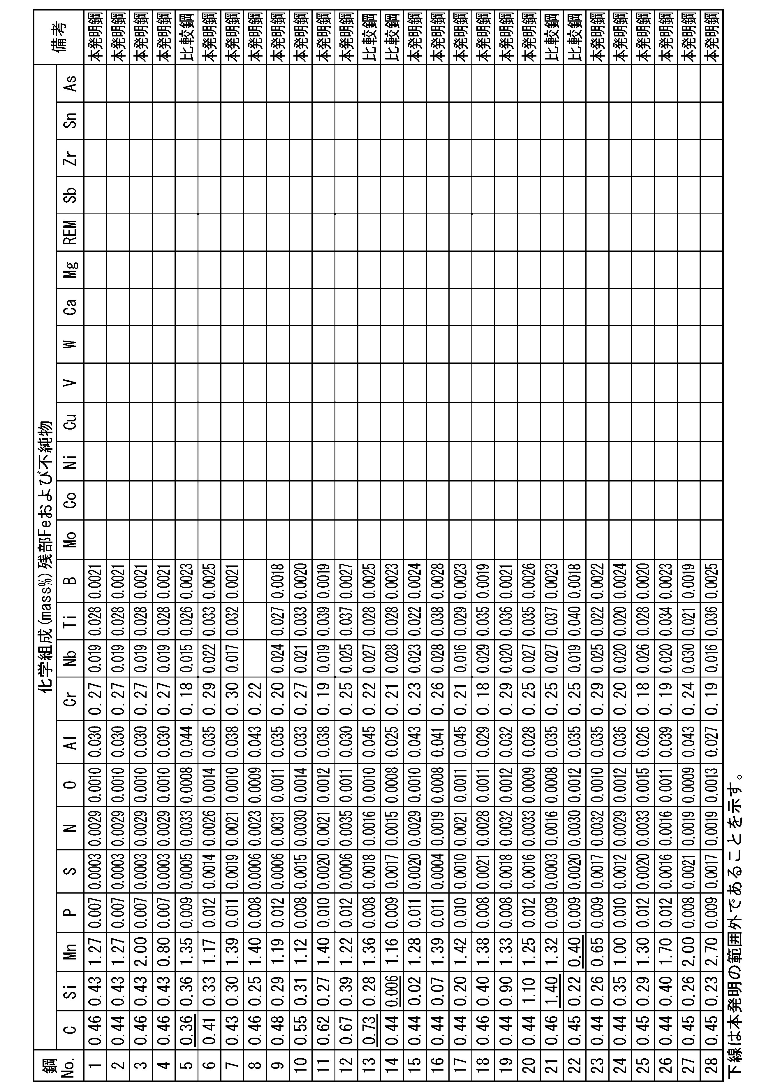
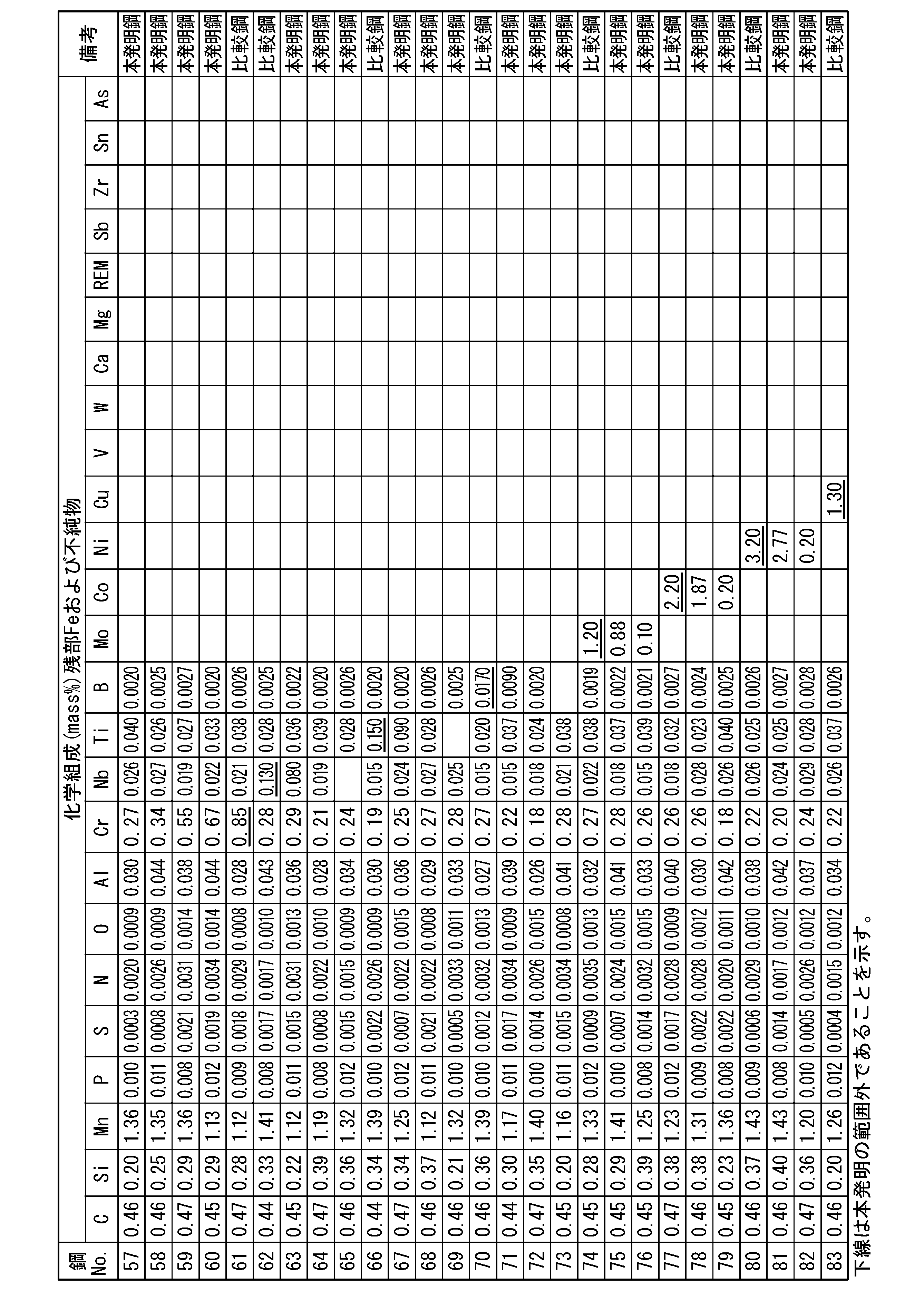
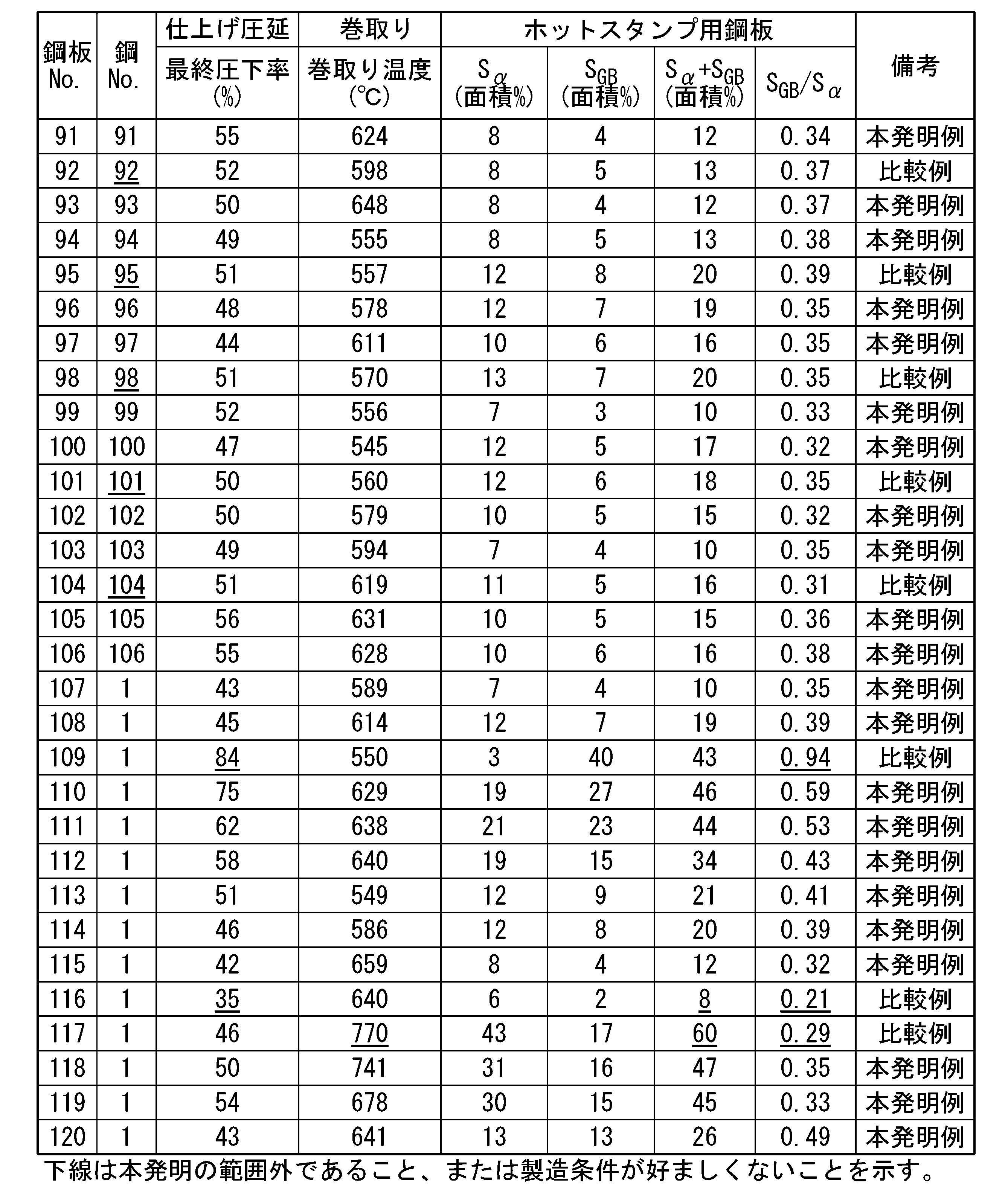
- a steel slab produced by casting molten steel having the chemical composition shown in Tables 1A to 1D is heated and held in a temperature range of 1200 ° C. or more and less than 1350 ° C. for 20 minutes or more, and then the conditions shown in Tables 2A to 2F.
- Hot rolling, cooling and coiling were performed at , and cold rolling, hot-rolled sheet annealing, pickling and plating were performed as necessary.
- steel sheets for hot stamping shown in Tables 2A to 2F were obtained.
- the average cooling rate for cooling up to coiling was set at 50 to 200° C./s.
- cooling was performed at the above-mentioned average cooling rate after 2.5 seconds or more had passed.
- the steel plate No. marked with "*”. No. 172 was cooled 2.0 seconds after finish rolling.
- steel plate No. In No. 107 in the casting process, the steel slab after solidification was rolled at a reduction ratio of 30 to 70% in a temperature range in which the center temperature of the slab is below the solidus temperature.
- Steel plate no. In No. 108 the heating temperature before hot rolling was 1350°C.
- Steel plate no. No. 125 was subjected to hot-rolled sheet annealing, which is heated and held in a temperature range of 730° C. or lower.
- Steel plate no. 126 was not cold rolled.
- Steel plate no. 127 formed an electrogalvanized layer on the surface.
- Steel plate no. 128 formed an electric Zn--Ni alloy plating layer on the surface.
- Steel plate no. 129 formed a hot-dip galvanized layer on the surface.
- Steel plate no. 130 formed an alloyed hot-dip galvanized layer on the surface.
- Steel plate no. 131 formed a hot-dip aluminum plating layer on the surface.
- Steel plate no. 132 formed a hot-dip Zn--Al alloy plating layer on the surface.
- Steel plate no. No. 133 formed a hot-dip Zn-Al-Mg alloy plating layer on the surface.
- Steel plate no. 134 formed a hot-dip Zn-Al-Mg-Si alloy plating layer on the surface.
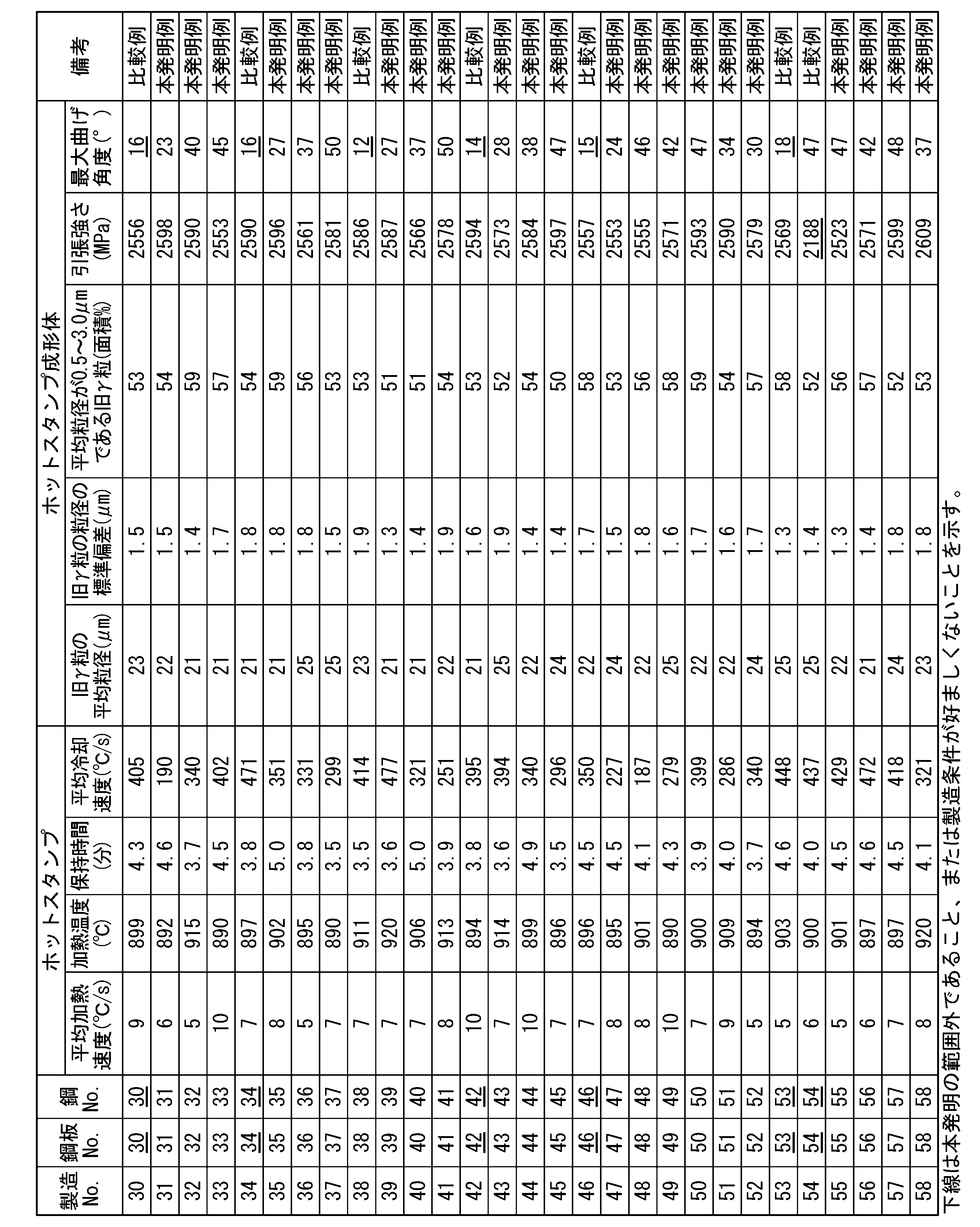
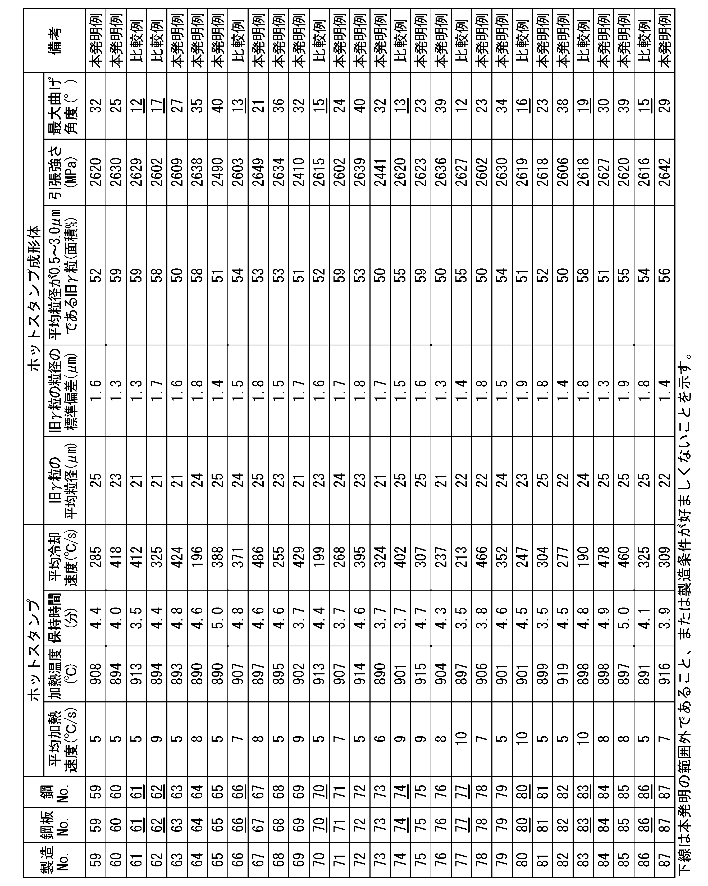
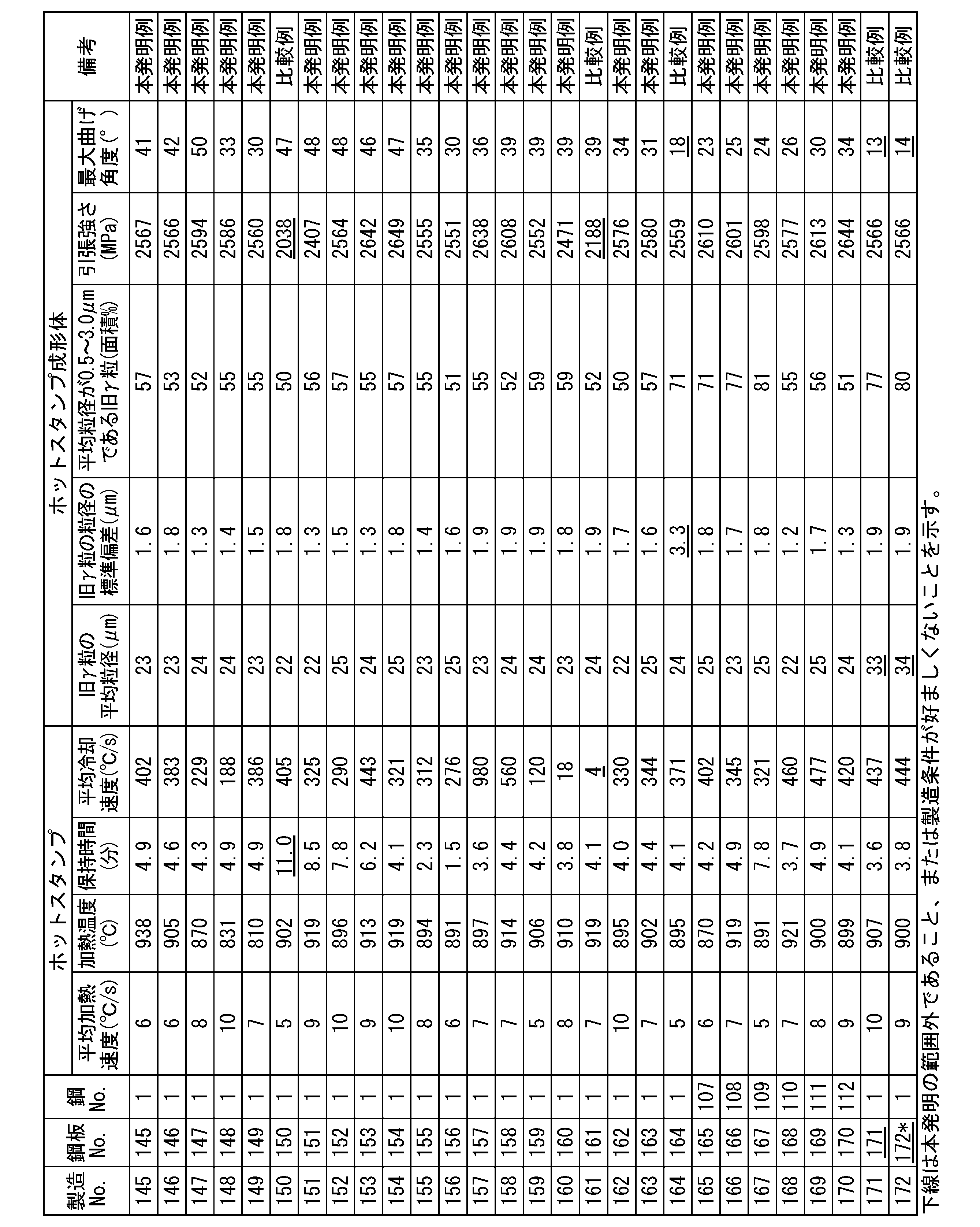
- the obtained steel sheets for hot stamping were subjected to hot stamping under the conditions shown in Tables 3A to 3F to obtain hot stamped bodies shown in Tables 3A to 3F.
- Manufacturing No. 161 was tempered at 150 to 600° C. after hot stamping.
- Manufacturing No. In No. 162 a partially softened region was formed by irradiating and tempering a portion of the hot-stamped body.
- Manufacturing No. 163 was heated to the heating temperature shown in Table 3F, cooled to a temperature range of 250° C. or less, then heated to 900° C. and then hot stamped, thereby cooling at the average cooling rate shown in Table 3D.
- the residual structure is one or more of pearlite, martensite, lower bainite, retained austenite and tempered martensite, and the total area ratio of these is It was more than 50% and 90% or less.
- the metal structures are, in area%, ferrite: 0 to 50%, bainite and martensite: 0 to 100%, pearlite: 0 to 30%, and retained austenite: It consisted of 0-5%.
- the method for measuring the metal structure of the hot stamping steel sheet and the method for measuring the metal structure and mechanical properties of the hot stamped product were as described above.
- the tensile strength of the hot stamped product was 2200 MPa or more, it was judged to have high strength and was judged to be acceptable.
- the maximum bending angle is 20 ° or more, it is judged to have excellent bendability and is judged to be acceptable, and if the maximum bending angle is less than 20 °, it is judged to be unacceptable because it does not have excellent bendability. did.
Landscapes
- Chemical & Material Sciences (AREA)
- Engineering & Computer Science (AREA)
- Mechanical Engineering (AREA)
- Materials Engineering (AREA)
- Metallurgy (AREA)
- Organic Chemistry (AREA)
- Crystallography & Structural Chemistry (AREA)
- Physics & Mathematics (AREA)
- Thermal Sciences (AREA)
- Heat Treatment Of Sheet Steel (AREA)
- Heat Treatment Of Articles (AREA)
- Coating With Molten Metal (AREA)
Abstract
Description
本願は、2021年5月13日に、日本に出願された特願2021-081620号に基づき優先権を主張し、その内容をここに援用する。
[1]本発明の一態様に係るホットスタンプ用鋼板は、化学組成が、質量%で、
C :0.40%超、0.70%以下、
Si:0.010~1.30%、
Mn:0.60%超、3.00%以下、
P :0.100%以下、
S :0.0100%以下、
N :0.0130%以下、
O :0.0200%以下、
Al:0.0010~0.500%、
Cr:0.010~0.80%、
Nb:0~0.100%、
Ti:0~0.100%、
B :0~0.0100%、
Mo:0~1.00%、
Co:0~2.00%、
Ni:0%以上、3.00%未満、
Cu:0~1.00%、
V :0~1.00%、
W :0~1.000%、
Ca:0~0.010%、
Mg:0~1.000%、
REM:0~1.000%、
Sb:0~1.000%、
Zr:0~1.000%、
Sn:0~1.000%、および
As:0~0.100%
を含有し、残部がFeおよび不純物からなり、
フェライトの面積率Sαおよびグラニュラーベイナイトの面積率SGBの合計であるSα+SGBが10%以上、50%未満であり、
前記グラニュラーベイナイトの前記面積率SGBと前記フェライトの前記面積率Sαとの比であるSGB/Sαが0.30~0.70である金属組織を有する。
[2]上記[1]に記載のホットスタンプ用鋼板は、前記化学組成が、質量%で、
Nb:0.001~0.100%、
Ti:0.010~0.100%、
B :0.0015~0.0100%、
Mo:0.05~1.00%、
Co:0.05~2.00%、
Ni:0.01%以上、3.00%未満、
Cu:0.01~1.00%、
V :0.01~1.00%、
W :0.001~1.000%、
Ca:0.001~0.010%、
Mg:0.001~1.000%、
REM:0.001~1.000%、
Sb:0.005~1.000%、および
Zr:0.001~1.000%、
Sn:0.001~1.000%、および
As:0.001~0.100%
からなる群から選択される1種または2種以上を含有してもよい。
[3]本発明の別の態様に係るホットスタンプ成形体は、化学組成が、質量%で、
C :0.40%超、0.70%以下、
Si:0.010~1.30%、
Mn:0.60%超、3.00%以下、
P :0.100%以下、
S :0.0100%以下、
N :0.0130%以下、
O :0.0200%以下、
Al:0.0010~0.500%、
Cr:0.010~0.80%、
Nb:0~0.100%、
Ti:0~0.100%、
B :0~0.0100%、
Mo:0~1.00%、
Co:0~2.00%、
Ni:0%以上、3.00%未満、
Cu:0~1.00%、
V :0~1.00%、
W :0~1.000%、
Ca:0~0.010%、
Mg:0~1.000%、
REM:0~1.000%、
Sb:0~1.000%、
Zr:0~1.000%、
Sn:0~1.000%、および
As:0~0.100%
を含有し、残部がFeおよび不純物からなり、
旧オーステナイト粒の平均粒径が5~25μmであり、前記旧オーステナイト粒の粒径の標準偏差が0.1~2.0μmである金属組織を有し、
引張強さが2200MPa以上である。
[4]上記[3]に記載のホットスタンプ成形体は、前記化学組成が、質量%で、
Nb:0.001~0.100%、
Ti:0.010~0.100%、
B :0.0015~0.0100%、
Mo:0.05~1.00%、
Co:0.05~2.00%、
Ni:0.01%以上、3.00%未満、
Cu:0.01~1.00%、
V :0.01~1.00%、
W :0.001~1.000%、
Ca:0.001~0.010%、
Mg:0.001~1.000%、
REM:0.001~1.000%、
Sb:0.005~1.000%、
Zr:0.001~1.000%、
Sn:0.001~1.000%、および
As:0.001~0.100%
からなる群から選択される1種または2種以上を含有してもよい。
[5]上記[3]または[4]に記載のホットスタンプ成形体は、平均粒径が0.5~3.0μmである前記旧オーステナイト粒の面積率が60%以下であってもよい。
なお、以下に記載する「~」を挟んで記載される数値限定範囲には、下限値および上限値がその範囲に含まれる。「未満」、「超」と示す数値には、その値が数値範囲に含まれない。化学組成についての%は全て質量%を示す。
Cは、ホットスタンプ成形体の強度の向上に大きく寄与する。C含有量が0.40%以下では、ホットスタンプ成形体において十分な強度を得ることが困難となる。そのため、C含有量は、0.40%超とする。好ましくは0.42%以上であり、より好ましくは0.45%以上であり、より一層好ましくは0.47%以上である。
一方、C含有量が0.70%超では、粗大な炭化物が生成してホットスタンプ成形体の曲げ性が劣化する。そのため、C含有量は、0.70%以下とする。好ましくは0.65%以下であり、より好ましくは0.60%以下である。
Siは、酸素と結合して破壊の起点となる酸化物の生成を抑制することで、ホットスタンプ成形体の変形能を向上する元素である。Si含有量が0.010%未満では、ホットスタンプ成形体において粗大な酸化物が形成して、所望の曲げ性を得ることができない。そのため、Si含有量は0.010%以上とする。好ましくは0.05%以上であり、より好ましくは0.10%以上である。
一方、Si含有量が1.30%超では、粗大な酸化物が生成してホットスタンプ成形体の曲げ性が劣化する。そのため、Si含有量は、1.30%以下とする。好ましくは1.00%未満であり、より好ましくは0.50%以下である。
Mnは、オーステナイトを安定化させて鋼板の焼入れ性を向上させる。Mn含有量が0.60%以下では、十分な焼入れ性が得られない。そのため、Mn含有量は0.60%超とする。好ましくは0.80%以上であり、より好ましくは1.20%以上である。
一方、Mn含有量が3.00%超では、粗大な介在物が生成してホットスタンプ成形体の曲げ性が劣化する。そのため、Mn含有量は3.00%以下とする。好ましくは2.20%以下であり、より好ましくは1.80%以下である。
Pは、鋼板の粒界に偏析して、ホットスタンプ成形体の曲げ性を劣化させたりする。そのため、P含有量は低ければ低いほど好ましい。特に、P含有量が0.100%超であると、鋼板の加工性およびホットスタンプ成形体の曲げ性が著しく劣化する。そのため、P含有量は0.100%以下とする。好ましくは0.080%以下であり、より好ましくは0.020%以下である。
P含有量の下限は特に限定しないが、0%であってもよい。ただし、P含有量を0.0001%未満に低減すると、脱Pコストが大幅に上昇し、経済的に好ましくない。そのため、P含有量は0.0001%以上としてもよい。
Sは、粗大な介在物を形成して、ホットスタンプ成形体の曲げ性を劣化させたりする。このため、S含有量は低ければ低いほど好ましい。特に、S含有量が0.0100%超であると、鋼板の成形性およびホットスタンプ成形体の曲げ性が著しく劣化する。そのため、S含有量は0.0100%以下とする。好ましくは0.0050%以下であり、より好ましくは0.0010%以下である。
S含有量の下限は特に限定しないが、0%であってもよい。ただし、S含有量を0.0001%未満に低減すると、脱Sコストが大幅に上昇し、経済的に好ましくない。そのため、S含有量は0.0001%以上としてもよい。
Nは、粗大な窒化物を形成して、ホットスタンプ成形体の曲げ性を劣化させたりする。このため、N含有量は低ければ低いほど好ましい。特に、N含有量が0.0130%超であると、鋼板の成形性が著しく劣化する。そのため、N含有量は0.0130%以下とする。好ましくは0.0100%以下または0.0070%以下であり、より好ましくは0.0040%以下である。
N含有量の下限は特に限定しないが、0%であってもよい。ただし、N含有量を0.0001%未満に低減すると、脱Nコストが大幅に上昇し、経済的に好ましくない。そのため、N含有量は0.0001%以上としてもよい。
Oは、鋼中に粗大な酸化物を形成し、ホットスタンプ成形体の曲げ性を劣化させる。このため、O含有量は低ければ低いほど好ましい。特に、O含有量が0.0200%超であると、ホットスタンプ成形体の曲げ性が著しく劣化する。そのため、O含有量は0.0200%以下とする。好ましくは0.0100%以下であり、より好ましくは0.0060%以下である。
O含有量の下限は特に限定しないが、0%であってもよい。ただし、O含有量を0.0001%未満に低減すると、製造コストが大幅に上昇し、経済的に好ましくない。そのため、O含有量は0.0001%以上としてもよい。
Alは、溶鋼を脱酸して、破壊の起点となる酸化物の生成を抑制することで変形能を向上し、ホットスタンプ成形体の曲げ性を高める元素である。Al含有量が0.0010%未満では、脱酸が十分に行われず、粗大な酸化物が生成して、上記効果を得ることができない。そのため、Al含有量は0.0010%以上とする。好ましくは0.010%以上であり、より好ましくは0.030%以上である。
一方、Al含有量が0.500%を超えると、鋼中に粗大な酸化物が生成し、ホットスタンプ成形体の曲げ性が低下する。そのため、Al含有量は0.500%以下とする。好ましくは0.450%以下であり、より好ましくは0.350%以下である。
Crは、ホットスタンプ時の加熱において旧オーステナイト粒に固溶することで、ホットスタンプ成形体の強度を高める。Cr含有量が0.010%未満では、この効果を得ることができない。そのため、Cr含有量は0.010%以上とする。好ましくは0.10%以上であり、より好ましくは0.20%以上である。
一方、Cr含有量が0.80%超であると、粗大な炭化物を形成してホットスタンプ成形体の曲げ性が劣化する。そのため、Cr含有量は0.80%以下とする。好ましくは0.60%以下であり、より好ましくは0.40%以下である。
Nbは、鋼中に炭窒化物を形成して、析出強化によりホットスタンプ成形体の強度を向上させる。この効果を得るためには、Nb含有量は0.001%以上とすることが好ましい。
一方、Nb含有量が0.100%超であると、鋼中に多量に炭窒化物が生成してホットスタンプ成形体の曲げ性が低下する。そのため、Nb含有量は0.100%以下とする。
Tiは、Nb同様、鋼中に炭窒化物を形成して、析出強化によりホットスタンプ成形体の強度を向上させる。この効果を得るためには、Ti含有量は0.010%以上とすることが好ましい。
一方、Ti含有量が0.100%超であると、鋼中に多量に炭窒化物が生成してホットスタンプ成形体の曲げ性が低下する。そのため、Ti含有量は0.100%以下とする。
Bは、鋼の焼き入れ性を向上させてホットスタンプ成形体の強度を向上させる。この効果を得るためには、B含有量は0.0015%以上とすることが好ましい。
一方、B含有量が0.0100%超であると、粗大な炭化物が生成してホットスタンプ成形体の曲げ性が劣化する。そのため、B含有量は0.0100%以下とする。
Moは、鋼板の焼き入れ性を向上させてホットスタンプ成形体の強度を向上させる。この効果を得るためには、Mo含有量を0.05%以上とすることが好ましい。
一方、Mo含有量が1.00%超であると、粗大な炭化物が生成してホットスタンプ成形体の曲げ性が劣化する。そのため、Mo含有量は、1.00%以下とする。
Coは、鋼板の焼き入れ性を向上させてホットスタンプ成形体の強度を向上させる。この効果を確実に発揮させるためには、Co含有量は0.05%以上とすることが好ましい。
一方、Co含有量が2.00%を超えると、粗大な炭化物が生成してホットスタンプ成形体の曲げ性が劣化する。そのため、Co含有量は2.00%以下とする。
Niは、鋼板の焼き入れ性を向上させてホットスタンプ成形体の強度を向上させる。この効果を得るためには、Ni含有量は0.01%以上とすることが好ましい。
一方、Ni含有量が3.00%以上であると、偏析が助長されてホットスタンプ成形体の曲げ性が劣化する。そのため、Ni含有量は3.00%未満とする。
Cuは、Ni同様、鋼板の焼き入れ性を向上させてホットスタンプ成形体の強度を向上させる。この効果を得るためには、Cu含有量は0.01%以上とすることが好ましい。
一方、Cu含有量が1.00%超であると、偏析が助長されてホットスタンプ成形体の曲げ性が劣化する。そのため、Cu含有量は1.00%以下とする。
Vは、鋼板の焼き入れ性を向上させてホットスタンプ成形体の強度を向上させる。この効果を得るために、V含有量は、0.01%以上とすることが好ましい。
一方で、V含有量が1.00%超であると、粗大な炭化物が生成してホットスタンプ成形体の曲げ性が劣化する。そのため、V含有量は1.00%以下とする。
Wは、鋼板の焼き入れ性を向上させてホットスタンプ成形体の強度を向上させる。この効果を得るためには、W含有量は0.001%以上とすることが好ましい。
一方、W含有量が1.000%超であると、偏析が助長されてホットスタンプ成形体の曲げ性が劣化する。そのため、W含有量は1.000%以下とする。
Caは、破壊の起点となる酸化物の生成を抑制することで変形能を向上し、ホットスタンプ成形体の曲げ性を高める。この効果を確実に得るために、Ca含有量を0.001%以上とすることが好ましい。
一方、Ca含有量が0.010%超であると、粗大な酸化物が生成してホットスタンプ成形体の曲げ性が劣化する。そのため、Ca含有量は0.010%以下とする。
Mgは、破壊の起点となる酸化物の生成を抑制することで変形能を向上し、ホットスタンプ成形体の曲げ性を高める。この効果を得るためには、Mg含有量は0.001%以上とすることが好ましい。
一方、Mg含有量が1.000%超であると、粗大な酸化物が生成してホットスタンプ成形体の曲げ性が劣化する。そのため、Mg含有量は1.000%以下とする。
REMは、破壊の起点となる酸化物の生成を抑制することで変形能を向上し、ホットスタンプ成形体の曲げ性を高める。この効果を得るために、REM含有量を0.001%以上とすることが好ましい。
一方、REM含有量が1.000%超であると、粗大な酸化物が生成してホットスタンプ成形体の曲げ性が劣化する。そのため、REM含有量は1.000%以下とする。
なお、本実施形態においてREMとは、Sc、Y及びランタノイドからなる合計17元素を指し、REMの含有量とはこれらの元素の合計含有量を指す。
Sbは、破壊の起点となる酸化物の生成を抑制することで変形能を向上し、ホットスタンプ成形体の曲げ性を高める。この効果を得るためには、Sb含有量は0.005%以上とすることが好ましい。
一方、Sb含有量が1.000%超であると、粗大な酸化物が生成してホットスタンプ成形体の曲げ性が劣化する。そのため、Sb含有量は1.000%以下とする。
Zrは、破壊の起点となる酸化物の生成を抑制することで変形能を向上し、ホットスタンプ成形体の曲げ性を高める。この効果を得るためには、Zr含有量は0.001%以上とすることが好ましい。
一方、Zr含有量を1.000%超とすると、粗大な酸化物が生成してホットスタンプ成形体の曲げ性が劣化する。そのため、Zr含有量は1.000%以下とする。
Snは、破壊の起点となる酸化物の生成を抑制することで変形能を向上し、ホットスタンプ成形体の曲げ性を高める。この効果を確実に得る場合、Sn含有量は0.001%以上とすることが好ましい。
一方、多量に含有させても上記効果は飽和するため、Sn含有量は1.000%以下とする。
Asは、オーステナイト単相化温度を低下させることにより、旧オーステナイト粒を細粒化させて、ホットスタンプ成形体の曲げ性を高める。この効果を確実に得る場合、As含有量は0.001%以上とすることが好ましい。
一方、多量に含有させても上記効果は飽和するため、As含有量は0.100%以下とする。
本実施形態に係るホットスタンプ用鋼板は、フェライトの面積率Sαおよびグラニュラーベイナイトの面積率SGBの合計であるSα+SGBが10%以上、50%未満であり、前記グラニュラーベイナイトの前記面積率SGBと前記フェライトの前記面積率Sαとの比であるSGB/Sαが0.30~0.70である金属組織を有する。以下、各規定について説明する。
なお、本実施形態では、圧延方向に平行な板厚断面の、表面から板厚の1/4深さ位置(表面から板厚の1/8深さ~表面から板厚の3/8深さの領域)における金属組織を規定する。その理由は、この位置における金属組織が、鋼板の代表的な金属組織を示すからである。
フェライトの面積率Sαおよびグラニュラーベイナイトの面積率SGBの合計であるSα+SGBが10%未満であると、ホットスタンプ成形体において旧オーステナイト粒を整粒化することができず、結果として、曲げ性に優れるホットスタンプ成形体を得ることができない。フェライトとグラニュラーベイナイトの炭素の固溶限が低いため、Sα+SGBを10%以上とし、且つ後述のSGB/Sαを所望の範囲内とすることで、炭素がフェライト粒界へと拡散し、フェライト粒界に炭素の偏析領域が形成する。ホットスタンプ時には、炭素の偏析領域が旧オーステナイト粒の起点となることで、旧オーステナイト粒が均一に分散して生成する。その結果、ホットスタンプ成形体において旧オーステナイト粒を整粒化することができると推測される。Sα+SGBは20%以上が好ましく、30%以上がより好ましい。
一方、Sα+SGBが50%以上であると、フェライト粒界への炭素の偏析が促進されすぎてフェライト粒界における炭化物の生成密度が増加し、ホットスタンプ後に旧オーステナイト粒が均一に分散して生成することができない。Sα+SGBは40%以下が好ましい。
SGB/Sαは0.30~0.70とする。フェライトは亜粒界を含まないためグラニュラーベイナイトよりも粒内に炭素が偏析しにくく、フェライトおよびグラニュラーベイナイトの面積比を上記範囲に制御することによってフェライト粒界における炭素の偏析量を高めることができる。グラニュラーベイナイトの結晶粒に含まれる亜粒界は、炭素の偏析起点となりうるため、ホットスタンプ加熱時に旧オーステナイトの起点として機能する。これにより、ホットスタンプ成形体において旧オーステナイト粒の平均粒径を25μm以下に制御することができる。SGB/Sαは、好ましくは0.40以上である。
一方、SGB/Sαが0.70超であると、亜粒界への炭素の偏析が促進されすぎて、ホットスタンプ加熱時にオーステナイト粒の隣接距離が近くなるため、旧オーステナイト粒の平均粒径を5μm以上に制御することができない。そのため、SGB/Sαは0.70以下とする。好ましくは0.50以下である。
ホットスタンプ用鋼板の端面から50mm以上離れた任意の位置(この位置からサンプルを採取できない場合は、端部を避けた位置)から、圧延方向に平行な板厚断面が観察できるようにサンプルを切り出す。サンプルの大きさは、測定装置にもよるが、圧延方向に10mm程度観察できる大きさとする。
なお、本実施形態では、板面に直角な断面の、表面から板厚の1/4深さ位置(表面から板厚の1/8深さ~表面から板厚の3/8深さの領域)における金属組織を規定する。その理由は、この位置における金属組織が、ホットスタンプ成形体の代表的な金属組織を示すからである。以下、金属組織について説明する。
「旧オーステナイト粒の粒径の標準偏差が0.1~2.0μm」
ホットスタンプ成形体の金属組織において、旧オーステナイト粒の平均粒径を5~25μmとし、且つ旧オーステナイト粒の粒径の標準偏差を0.1~2.0μmとすることで、ホットスタンプ成形体の曲げ性を向上することができる。旧オーステナイト粒の平均粒径または旧オーステナイト粒の粒径の標準偏差が上記範囲外であると、ホットスタンプ成形体において優れた曲げ性を得ることができない。
旧オーステナイト粒の粒径の標準偏差を2.0μm以下とすることで、ホットスタンプ成形体において優れた曲げ性を得ることができる。そのため、旧オーステナイト粒の粒径の標準偏差は2.0μm以下とする。より好ましくは1.2μm以下であり、より一層好ましくは1.1μm以下であり、さらに好ましくは0.4μm以下である。
実操業上、旧オーステナイト粒の粒径の標準偏差を0.1μm未満とすることは難しいので、実質の下限は0.1μm以上となる。
次に、旧オーステナイト粒の平均結晶粒径の測定方法について説明する。ホットスタンプ成形体の端面から50mm以上離れた任意の位置(この位置からサンプルを採取できない場合は、端部を避けた位置)から、圧延方向に平行な板厚断面が観察できるようにサンプルを切り出す。サンプルの大きさは、測定装置にもよるが、圧延方向に10mm程度観察できる大きさとする。上記サンプルの断面を#600から#1500の炭化珪素ペーパーを使用して研磨した後、粒度1~6μmのダイヤモンドパウダーをアルコール等の希釈液や純水に分散させた液体を使用して鏡面に仕上げ、電解研磨を用いて仕上げ研磨を施す。
平均粒径が0.5~3.0μmである旧オーステナイト粒の面積を測定視野全体の面積で除した値を算出することで、平均粒径が0.5~3.0μmである旧オーステナイト粒の面積率を得る。
ホットスタンプ成形体の端面から50mm以上離れた任意の位置(この位置からサンプルを採取できない場合は、端部を避けた位置)から、板面に直角な断面が観察できるようにサンプルを切り出す。このサンプルの断面を#600から#1500の炭化珪素ペーパーを使用して研磨した後、粒度1~6μmのダイヤモンドパウダーをアルコール等の希釈液や純水に分散させた液体を使用して鏡面に仕上げ、ナイタールエッチングを施す。表面から板厚の1/4深さ位置が観察できるように、サンプル断面の長手方向の任意の位置における、長さ50μm、表面から板厚の1/8深さ~表面から板厚の3/8深さの領域において、サーマル電界放射型走査電子顕微鏡(JEOL製JSM-7001F)を用いて複数視野の写真を撮影する。撮影写真上に等間隔の格子を描き、格子点における組織を同定する。各組織に該当する格子点数を求め、総格子点数で除することにより、各組織の面積率を得る。総格子点数が多いほど面積率を正確に求めることができる。本実施形態では、格子間隔は2μm×2μmとし、総格子点数は1500点とする。
マルテンサイトの面積率については、上記の撮影写真から求めたマルテンサイトおよび残留オーステナイトの面積率から、後述のEBSD解析により求めた残留オーステナイトの面積率を差し引くことで得る。
試験片板厚:1.6mm
曲げ稜線:板幅方向に平行な方向
試験方法:ロール支持、ポンチ押し込み
ロール径:φ30mm
ポンチ形状:先端R=0.4mm
ロール間距離:2.0×板厚(mm)+0.5mm
押し込み速度:20mm/min
試験機:SHIMADZU AUTOGRAPH 20kN
本実施形態に係るホットスタンプ用鋼板の製造方法では、上述した金属組織を有するホットスタンプ用鋼板を得るために、熱間圧延における仕上げ圧延の最終圧下率を40~80%とすることが好ましい。通常、仕上げ圧延の最終圧下率は10%未満であるが、本実施形態では通常の最終圧下率よりも高い最終圧下率とすることが好ましい。
なお、上記式(1)中において、%C、%Si、%Mn、%P、%S、%Ni、%Crおよび%Alは各元素の含有量(質量%)を意味する。
なお、熱間圧延前の鋼片の加熱温度および保持時間は特に限定されないが、1200℃以上の温度域で20分以上保持することが好ましい。
また、巻取り温度は、400℃以上が好ましい。巻取り温度が400℃未満であるとグラニュラーベイナイトの生成が抑制されてSGB/Sαが0.30未満となる。巻取り温度は、好ましくは450℃以上であり、より好ましくは530℃以上である。
また、仕上げ圧延後(熱間圧延完了後)は、2.5秒以上経過してから冷却を行うことが好ましい。ここでいう冷却とは、空冷を含まず、且つ、平均冷却速度が50~200℃/sの冷却のことである。仕上げ圧延後、冷却開始までの時間が2.5秒未満であると、所望量のSα+SGBを得ることができない場合がある。
加熱温度の上限は特に限定しないが、加熱温度が高すぎると鋼板表層において脱炭が助長されて、ホットスタンプ成形体の強度が低下する。そのため、加熱温度は1000℃以下であることが好ましく、960℃以下であることがより好ましく、930℃以下であることがより一層好ましい。
なお、ホットスタンプ時の加熱において、予備加熱すること、すなわち2段階の加熱を行うことは好ましくない。ホットスタンプ用鋼板の段階で作りこんだ粒界における炭素の偏析領域が解消され、旧オーステナイト粒を均一に分散して生成させることができず、結果として旧オーステナイト粒の標準偏差を所望の範囲内に制御することができないためである。
鋼板No.108は、熱間圧延前の加熱温度を1350℃とした。
鋼板No.125は、730℃以下の温度域に加熱して保持する、熱延板焼鈍を施した。
鋼板No.126は、冷間圧延を行わなかった。
鋼板No.127は、表面に電気亜鉛めっき層を形成した。
鋼板No.128は、表面に電気Zn-Ni合金めっき層を形成した。
鋼板No.129は、表面に溶融亜鉛めっき層を形成した。
鋼板No.130は、表面に合金化溶融亜鉛めっき層を形成した。
鋼板No.131は、表面に溶融アルミニウムめっき層を形成した。
鋼板No.132は、表面に溶融Zn-Al合金めっき層を形成した。
鋼板No.133は、表面に溶融Zn-Al-Mg合金めっき層を形成した。
鋼板No.134は、表面に溶融Zn-Al-Mg-Si合金めっき層を形成した。
製造No.161は、ホットスタンプ後に150~600℃で焼戻し処理を行った。
製造No.162は、ホットスタンプ成形体の一部分をレーザー照射して焼戻すことで、部分軟化領域を形成した。
製造No.163は、表3Fに記載の加熱温度まで加熱した後、250℃以下の温度域まで冷却し、その後900℃まで加熱してからホットスタンプすることで、表3D中の平均冷却速度で冷却した。
また、最大曲げ角度が20°以上であった場合、優れた曲げ性を有するとして合格と判定し、最大曲げ角度が20°未満であった場合、優れた曲げ性を有しないとして不合格と判定した。







Claims (5)
- 化学組成が、質量%で、
C :0.40%超、0.70%以下、
Si:0.010~1.30%、
Mn:0.60%超、3.00%以下、
P :0.100%以下、
S :0.0100%以下、
N :0.0130%以下、
O :0.0200%以下、
Al:0.0010~0.500%、
Cr:0.010~0.80%、
Nb:0~0.100%、
Ti:0~0.100%、
B :0~0.0100%、
Mo:0~1.00%、
Co:0~2.00%、
Ni:0%以上、3.00%未満、
Cu:0~1.00%、
V :0~1.00%、
W :0~1.000%、
Ca:0~0.010%、
Mg:0~1.000%、
REM:0~1.000%、
Sb:0~1.000%、
Zr:0~1.000%、
Sn:0~1.000%、および
As:0~0.100%
を含有し、残部がFeおよび不純物からなり、
フェライトの面積率Sαおよびグラニュラーベイナイトの面積率SGBの合計であるSα+SGBが10%以上、50%未満であり、
前記グラニュラーベイナイトの前記面積率SGBと前記フェライトの前記面積率Sαとの比であるSGB/Sαが0.30~0.70である金属組織を有することを特徴とする、ホットスタンプ用鋼板。 - 前記化学組成が、質量%で、
Nb:0.001~0.100%、
Ti:0.010~0.100%、
B :0.0015~0.0100%、
Mo:0.05~1.00%、
Co:0.05~2.00%、
Ni:0.01%以上、3.00%未満、
Cu:0.01~1.00%、
V :0.01~1.00%、
W :0.001~1.000%、
Ca:0.001~0.010%、
Mg:0.001~1.000%、
REM:0.001~1.000%、
Sb:0.005~1.000%、
Zr:0.001~1.000%、
Sn:0.001~1.000%、および
As:0.001~0.100%
からなる群から選択される1種または2種以上を含有することを特徴とする、請求項1に記載のホットスタンプ用鋼板。 - 化学組成が、質量%で、
C :0.40%超、0.70%以下、
Si:0.010~1.30%、
Mn:0.60%超、3.00%以下、
P :0.100%以下、
S :0.0100%以下、
N :0.0130%以下、
O :0.0200%以下、
Al:0.0010~0.500%、
Cr:0.010~0.80%、
Nb:0~0.100%、
Ti:0~0.100%、
B :0~0.0100%、
Mo:0~1.00%、
Co:0~2.00%、
Ni:0%以上、3.00%未満、
Cu:0~1.00%、
V :0~1.00%、
W :0~1.000%、
Ca:0~0.010%、
Mg:0~1.000%、
REM:0~1.000%、
Sb:0~1.000%、
Zr:0~1.000%、
Sn:0~1.000%、および
As:0~0.100%
を含有し、残部がFeおよび不純物からなり、
旧オーステナイト粒の平均粒径が5~25μmであり、前記旧オーステナイト粒の粒径の標準偏差が0.1~2.0μmである金属組織を有し、
引張強さが2200MPa以上であることを特徴とする、ホットスタンプ成形体。 - 前記化学組成が、質量%で、
Nb:0.001~0.100%、
Ti:0.010~0.100%、
B :0.0015~0.0100%、
Mo:0.05~1.00%、
Co:0.05~2.00%、
Ni:0.01%以上、3.00%未満、
Cu:0.01~1.00%、
V :0.01~1.00%、
W :0.001~1.000%、
Ca:0.001~0.010%、
Mg:0.001~1.000%、
REM:0.001~1.000%、
Sb:0.005~1.000%、
Zr:0.001~1.000%、
Sn:0.001~1.000%、および
As:0.001~0.100%
からなる群から選択される1種または2種以上を含有することを特徴とする、請求項3に記載のホットスタンプ成形体。 - 平均粒径が0.5~3.0μmである前記旧オーステナイト粒の面積率が60%以下であることを特徴とする、請求項3または4に記載のホットスタンプ成形体。
Priority Applications (6)
| Application Number | Priority Date | Filing Date | Title |
|---|---|---|---|
| KR1020237029584A KR102932262B1 (ko) | 2021-05-13 | 2022-05-09 | 핫 스탬프용 강판 및 핫 스탬프 성형체 |
| JP2023521010A JP7787431B2 (ja) | 2021-05-13 | 2022-05-09 | ホットスタンプ用鋼板およびホットスタンプ成形体 |
| US18/279,370 US20240183015A1 (en) | 2021-05-13 | 2022-05-09 | Steel sheet for hot stamping and hot-stamping formed body |
| EP22807432.4A EP4286544A4 (en) | 2021-05-13 | 2022-05-09 | STEEL SHEET FOR HOT STAMPING, AND BODY MOLDED BY HOT STAMPING |
| MX2023010146A MX2023010146A (es) | 2021-05-13 | 2022-05-09 | Lamina de acero para estampado en caliente y cuerpo formado por estampado en caliente. |
| CN202280018830.XA CN116917524B (zh) | 2021-05-13 | 2022-05-09 | 热冲压用钢板及热冲压成型体 |
Applications Claiming Priority (2)
| Application Number | Priority Date | Filing Date | Title |
|---|---|---|---|
| JP2021081620 | 2021-05-13 | ||
| JP2021-081620 | 2021-05-13 |
Publications (1)
| Publication Number | Publication Date |
|---|---|
| WO2022239731A1 true WO2022239731A1 (ja) | 2022-11-17 |
Family
ID=84029645
Family Applications (1)
| Application Number | Title | Priority Date | Filing Date |
|---|---|---|---|
| PCT/JP2022/019656 Ceased WO2022239731A1 (ja) | 2021-05-13 | 2022-05-09 | ホットスタンプ用鋼板およびホットスタンプ成形体 |
Country Status (7)
| Country | Link |
|---|---|
| US (1) | US20240183015A1 (ja) |
| EP (1) | EP4286544A4 (ja) |
| JP (1) | JP7787431B2 (ja) |
| KR (1) | KR102932262B1 (ja) |
| CN (1) | CN116917524B (ja) |
| MX (1) | MX2023010146A (ja) |
| WO (1) | WO2022239731A1 (ja) |
Cited By (4)
| Publication number | Priority date | Publication date | Assignee | Title |
|---|---|---|---|---|
| JPWO2023189183A1 (ja) * | 2022-03-31 | 2023-10-05 | ||
| WO2023189175A1 (ja) * | 2022-03-31 | 2023-10-05 | 日本製鉄株式会社 | ホットスタンプ用鋼板及びホットスタンプ成形体 |
| WO2023234337A1 (ja) * | 2022-06-03 | 2023-12-07 | 日本製鉄株式会社 | ホットスタンプ成形体 |
| KR102958853B1 (ko) | 2022-03-31 | 2026-05-04 | 닛폰세이테츠 가부시키가이샤 | 핫 스탬프 성형체 |
Families Citing this family (1)
| Publication number | Priority date | Publication date | Assignee | Title |
|---|---|---|---|---|
| KR102900041B1 (ko) * | 2021-05-13 | 2025-12-15 | 닛폰세이테츠 가부시키가이샤 | 핫 스탬프용 강판 및 핫 스탬프 성형체 |
Citations (7)
| Publication number | Priority date | Publication date | Assignee | Title |
|---|---|---|---|---|
| JP2007262469A (ja) * | 2006-03-28 | 2007-10-11 | Jfe Steel Kk | 鋼管およびその製造方法 |
| JP2014118613A (ja) * | 2012-12-18 | 2014-06-30 | Nippon Steel & Sumitomo Metal | 強度と耐水素脆性に優れたホットスタンプ成形体及びその製造方法 |
| WO2018134874A1 (ja) | 2017-01-17 | 2018-07-26 | 新日鐵住金株式会社 | ホットスタンプ成形体及びその製造方法 |
| WO2020189767A1 (ja) * | 2019-03-20 | 2020-09-24 | 日本製鉄株式会社 | ホットスタンプ成形体 |
| WO2020195012A1 (ja) * | 2019-03-25 | 2020-10-01 | 日本製鉄株式会社 | ホットスタンプ用鋼板 |
| WO2020241764A1 (ja) * | 2019-05-31 | 2020-12-03 | 日本製鉄株式会社 | ホットスタンプ成形体 |
| JP2021081620A (ja) | 2019-11-20 | 2021-05-27 | キヤノン株式会社 | 電子機器 |
Family Cites Families (6)
| Publication number | Priority date | Publication date | Assignee | Title |
|---|---|---|---|---|
| CN105506509B (zh) * | 2014-09-26 | 2017-07-21 | 鞍钢股份有限公司 | 一种高强度热浸镀铝钢板及其制造方法 |
| MX2019004457A (es) * | 2017-01-30 | 2019-06-24 | Nippon Steel & Sumitomo Metal Corp | Lamina de acero. |
| US20200232056A1 (en) | 2017-02-20 | 2020-07-23 | Nippon Steel Corporation | Hot stamped body |
| WO2019003447A1 (ja) * | 2017-06-30 | 2019-01-03 | Jfeスチール株式会社 | 熱間プレス部材およびその製造方法ならびに熱間プレス用冷延鋼板 |
| JP7036274B2 (ja) * | 2019-03-15 | 2022-03-15 | 日本製鉄株式会社 | 鋼板 |
| US12054800B2 (en) * | 2019-05-31 | 2024-08-06 | Nippon Steel Corporation | Steel sheet for hot stamping |
-
2022
- 2022-05-09 US US18/279,370 patent/US20240183015A1/en active Pending
- 2022-05-09 KR KR1020237029584A patent/KR102932262B1/ko active Active
- 2022-05-09 JP JP2023521010A patent/JP7787431B2/ja active Active
- 2022-05-09 WO PCT/JP2022/019656 patent/WO2022239731A1/ja not_active Ceased
- 2022-05-09 CN CN202280018830.XA patent/CN116917524B/zh active Active
- 2022-05-09 EP EP22807432.4A patent/EP4286544A4/en active Pending
- 2022-05-09 MX MX2023010146A patent/MX2023010146A/es unknown
Patent Citations (7)
| Publication number | Priority date | Publication date | Assignee | Title |
|---|---|---|---|---|
| JP2007262469A (ja) * | 2006-03-28 | 2007-10-11 | Jfe Steel Kk | 鋼管およびその製造方法 |
| JP2014118613A (ja) * | 2012-12-18 | 2014-06-30 | Nippon Steel & Sumitomo Metal | 強度と耐水素脆性に優れたホットスタンプ成形体及びその製造方法 |
| WO2018134874A1 (ja) | 2017-01-17 | 2018-07-26 | 新日鐵住金株式会社 | ホットスタンプ成形体及びその製造方法 |
| WO2020189767A1 (ja) * | 2019-03-20 | 2020-09-24 | 日本製鉄株式会社 | ホットスタンプ成形体 |
| WO2020195012A1 (ja) * | 2019-03-25 | 2020-10-01 | 日本製鉄株式会社 | ホットスタンプ用鋼板 |
| WO2020241764A1 (ja) * | 2019-05-31 | 2020-12-03 | 日本製鉄株式会社 | ホットスタンプ成形体 |
| JP2021081620A (ja) | 2019-11-20 | 2021-05-27 | キヤノン株式会社 | 電子機器 |
Non-Patent Citations (2)
| Title |
|---|
| ACTA MATERIALIA, vol. 58, 2010, pages 6393 - 6403 |
| See also references of EP4286544A4 |
Cited By (8)
| Publication number | Priority date | Publication date | Assignee | Title |
|---|---|---|---|---|
| JPWO2023189183A1 (ja) * | 2022-03-31 | 2023-10-05 | ||
| WO2023189183A1 (ja) * | 2022-03-31 | 2023-10-05 | 日本製鉄株式会社 | ホットスタンプ成形体 |
| WO2023189175A1 (ja) * | 2022-03-31 | 2023-10-05 | 日本製鉄株式会社 | ホットスタンプ用鋼板及びホットスタンプ成形体 |
| JP7737060B2 (ja) | 2022-03-31 | 2025-09-10 | 日本製鉄株式会社 | ホットスタンプ成形体 |
| KR102958853B1 (ko) | 2022-03-31 | 2026-05-04 | 닛폰세이테츠 가부시키가이샤 | 핫 스탬프 성형체 |
| WO2023234337A1 (ja) * | 2022-06-03 | 2023-12-07 | 日本製鉄株式会社 | ホットスタンプ成形体 |
| JPWO2023234337A1 (ja) * | 2022-06-03 | 2023-12-07 | ||
| JP7780113B2 (ja) | 2022-06-03 | 2025-12-04 | 日本製鉄株式会社 | ホットスタンプ成形体 |
Also Published As
| Publication number | Publication date |
|---|---|
| KR20230137436A (ko) | 2023-10-04 |
| JP7787431B2 (ja) | 2025-12-17 |
| KR102932262B1 (ko) | 2026-03-04 |
| US20240183015A1 (en) | 2024-06-06 |
| MX2023010146A (es) | 2023-09-11 |
| EP4286544A4 (en) | 2024-07-31 |
| JPWO2022239731A1 (ja) | 2022-11-17 |
| EP4286544A1 (en) | 2023-12-06 |
| CN116917524B (zh) | 2026-01-13 |
| CN116917524A (zh) | 2023-10-20 |
Similar Documents
| Publication | Publication Date | Title |
|---|---|---|
| KR102643398B1 (ko) | 핫 스탬프 성형체 | |
| JP7436917B2 (ja) | ホットスタンプ用鋼板およびホットスタンプ成形体 | |
| CN113544296B (zh) | 热冲压成形体 | |
| JP7787431B2 (ja) | ホットスタンプ用鋼板およびホットスタンプ成形体 | |
| JP7151890B2 (ja) | ホットスタンプ成形体 | |
| JP7436916B2 (ja) | ホットスタンプ成形体 | |
| KR102900041B1 (ko) | 핫 스탬프용 강판 및 핫 스탬프 성형체 | |
| JP7319571B2 (ja) | ホットスタンプ成形体 | |
| JP7350057B2 (ja) | ホットスタンプ成形体 | |
| JP7366121B2 (ja) | ホットスタンプ用鋼板 | |
| JP7188585B2 (ja) | ホットスタンプ成形体 | |
| JP7188584B2 (ja) | ホットスタンプ成形体 | |
| JP7188583B2 (ja) | ホットスタンプ用鋼板 | |
| KR102936226B1 (ko) | 핫 스탬프용 강판 및 핫 스탬프 성형체 | |
| KR102662619B1 (ko) | 핫 스탬프 성형체 |
Legal Events
| Date | Code | Title | Description |
|---|---|---|---|
| 121 | Ep: the epo has been informed by wipo that ep was designated in this application |
Ref document number: 22807432 Country of ref document: EP Kind code of ref document: A1 |
|
| WWE | Wipo information: entry into national phase |
Ref document number: 2023521010 Country of ref document: JP |
|
| WWE | Wipo information: entry into national phase |
Ref document number: 202317055850 Country of ref document: IN |
|
| WWE | Wipo information: entry into national phase |
Ref document number: 18279370 Country of ref document: US Ref document number: 2022807432 Country of ref document: EP |
|
| ENP | Entry into the national phase |
Ref document number: 20237029584 Country of ref document: KR Kind code of ref document: A |
|
| WWE | Wipo information: entry into national phase |
Ref document number: MX/A/2023/010146 Country of ref document: MX |
|
| ENP | Entry into the national phase |
Ref document number: 2022807432 Country of ref document: EP Effective date: 20230829 |
|
| WWE | Wipo information: entry into national phase |
Ref document number: 202280018830.X Country of ref document: CN Ref document number: 2301005490 Country of ref document: TH |
|
| NENP | Non-entry into the national phase |
Ref country code: DE |