WO2022244416A1 - 複合正極活物質、正極材料、および電池 - Google Patents
複合正極活物質、正極材料、および電池 Download PDFInfo
- Publication number
- WO2022244416A1 WO2022244416A1 PCT/JP2022/011260 JP2022011260W WO2022244416A1 WO 2022244416 A1 WO2022244416 A1 WO 2022244416A1 JP 2022011260 W JP2022011260 W JP 2022011260W WO 2022244416 A1 WO2022244416 A1 WO 2022244416A1
- Authority
- WO
- WIPO (PCT)
- Prior art keywords
- positive electrode
- active material
- electrode active
- solid electrolyte
- coating
- Prior art date
- Legal status (The legal status is an assumption and is not a legal conclusion. Google has not performed a legal analysis and makes no representation as to the accuracy of the status listed.)
- Ceased
Links
Images



Classifications
-
- H—ELECTRICITY
- H01—ELECTRIC ELEMENTS
- H01M—PROCESSES OR MEANS, e.g. BATTERIES, FOR THE DIRECT CONVERSION OF CHEMICAL ENERGY INTO ELECTRICAL ENERGY
- H01M10/00—Secondary cells; Manufacture thereof
- H01M10/05—Accumulators with non-aqueous electrolyte
- H01M10/052—Li-accumulators
-
- H—ELECTRICITY
- H01—ELECTRIC ELEMENTS
- H01M—PROCESSES OR MEANS, e.g. BATTERIES, FOR THE DIRECT CONVERSION OF CHEMICAL ENERGY INTO ELECTRICAL ENERGY
- H01M10/00—Secondary cells; Manufacture thereof
- H01M10/05—Accumulators with non-aqueous electrolyte
- H01M10/056—Accumulators with non-aqueous electrolyte characterised by the materials used as electrolytes, e.g. mixed inorganic/organic electrolytes
- H01M10/0561—Accumulators with non-aqueous electrolyte characterised by the materials used as electrolytes, e.g. mixed inorganic/organic electrolytes the electrolyte being constituted of inorganic materials only
- H01M10/0562—Solid materials
-
- H—ELECTRICITY
- H01—ELECTRIC ELEMENTS
- H01M—PROCESSES OR MEANS, e.g. BATTERIES, FOR THE DIRECT CONVERSION OF CHEMICAL ENERGY INTO ELECTRICAL ENERGY
- H01M10/00—Secondary cells; Manufacture thereof
- H01M10/42—Methods or arrangements for servicing or maintenance of secondary cells or secondary half-cells
- H01M10/4235—Safety or regulating additives or arrangements in electrodes, separators or electrolyte
-
- H—ELECTRICITY
- H01—ELECTRIC ELEMENTS
- H01M—PROCESSES OR MEANS, e.g. BATTERIES, FOR THE DIRECT CONVERSION OF CHEMICAL ENERGY INTO ELECTRICAL ENERGY
- H01M4/00—Electrodes
- H01M4/02—Electrodes composed of, or comprising, active material
- H01M4/13—Electrodes for accumulators with non-aqueous electrolyte, e.g. for lithium-accumulators; Processes of manufacture thereof
- H01M4/131—Electrodes based on mixed oxides or hydroxides, or on mixtures of oxides or hydroxides, e.g. LiCoOx
-
- H—ELECTRICITY
- H01—ELECTRIC ELEMENTS
- H01M—PROCESSES OR MEANS, e.g. BATTERIES, FOR THE DIRECT CONVERSION OF CHEMICAL ENERGY INTO ELECTRICAL ENERGY
- H01M4/00—Electrodes
- H01M4/02—Electrodes composed of, or comprising, active material
- H01M4/13—Electrodes for accumulators with non-aqueous electrolyte, e.g. for lithium-accumulators; Processes of manufacture thereof
- H01M4/136—Electrodes based on inorganic compounds other than oxides or hydroxides, e.g. sulfides, selenides, tellurides, halogenides or LiCoFy
-
- H—ELECTRICITY
- H01—ELECTRIC ELEMENTS
- H01M—PROCESSES OR MEANS, e.g. BATTERIES, FOR THE DIRECT CONVERSION OF CHEMICAL ENERGY INTO ELECTRICAL ENERGY
- H01M4/00—Electrodes
- H01M4/02—Electrodes composed of, or comprising, active material
- H01M4/36—Selection of substances as active materials, active masses, active liquids
- H01M4/362—Composites
- H01M4/366—Composites as layered products
-
- H—ELECTRICITY
- H01—ELECTRIC ELEMENTS
- H01M—PROCESSES OR MEANS, e.g. BATTERIES, FOR THE DIRECT CONVERSION OF CHEMICAL ENERGY INTO ELECTRICAL ENERGY
- H01M4/00—Electrodes
- H01M4/02—Electrodes composed of, or comprising, active material
- H01M4/36—Selection of substances as active materials, active masses, active liquids
- H01M4/58—Selection of substances as active materials, active masses, active liquids of inorganic compounds other than oxides or hydroxides, e.g. sulfides, selenides, tellurides, halogenides or LiCoFy; of polyanionic structures, e.g. phosphates, silicates or borates
-
- H—ELECTRICITY
- H01—ELECTRIC ELEMENTS
- H01M—PROCESSES OR MEANS, e.g. BATTERIES, FOR THE DIRECT CONVERSION OF CHEMICAL ENERGY INTO ELECTRICAL ENERGY
- H01M4/00—Electrodes
- H01M4/02—Electrodes composed of, or comprising, active material
- H01M4/62—Selection of inactive substances as ingredients for active masses, e.g. binders, fillers
-
- H—ELECTRICITY
- H01—ELECTRIC ELEMENTS
- H01M—PROCESSES OR MEANS, e.g. BATTERIES, FOR THE DIRECT CONVERSION OF CHEMICAL ENERGY INTO ELECTRICAL ENERGY
- H01M10/00—Secondary cells; Manufacture thereof
- H01M10/05—Accumulators with non-aqueous electrolyte
- H01M10/052—Li-accumulators
- H01M10/0525—Rocking-chair batteries, i.e. batteries with lithium insertion or intercalation in both electrodes; Lithium-ion batteries
-
- H—ELECTRICITY
- H01—ELECTRIC ELEMENTS
- H01M—PROCESSES OR MEANS, e.g. BATTERIES, FOR THE DIRECT CONVERSION OF CHEMICAL ENERGY INTO ELECTRICAL ENERGY
- H01M4/00—Electrodes
- H01M4/02—Electrodes composed of, or comprising, active material
- H01M2004/026—Electrodes composed of, or comprising, active material characterised by the polarity
- H01M2004/028—Positive electrodes
-
- H—ELECTRICITY
- H01—ELECTRIC ELEMENTS
- H01M—PROCESSES OR MEANS, e.g. BATTERIES, FOR THE DIRECT CONVERSION OF CHEMICAL ENERGY INTO ELECTRICAL ENERGY
- H01M2300/00—Electrolytes
- H01M2300/0017—Non-aqueous electrolytes
- H01M2300/0065—Solid electrolytes
- H01M2300/0068—Solid electrolytes inorganic
-
- H—ELECTRICITY
- H01—ELECTRIC ELEMENTS
- H01M—PROCESSES OR MEANS, e.g. BATTERIES, FOR THE DIRECT CONVERSION OF CHEMICAL ENERGY INTO ELECTRICAL ENERGY
- H01M2300/00—Electrolytes
- H01M2300/0017—Non-aqueous electrolytes
- H01M2300/0065—Solid electrolytes
- H01M2300/0068—Solid electrolytes inorganic
- H01M2300/008—Halides
-
- H—ELECTRICITY
- H01—ELECTRIC ELEMENTS
- H01M—PROCESSES OR MEANS, e.g. BATTERIES, FOR THE DIRECT CONVERSION OF CHEMICAL ENERGY INTO ELECTRICAL ENERGY
- H01M4/00—Electrodes
- H01M4/02—Electrodes composed of, or comprising, active material
- H01M4/04—Processes of manufacture in general
- H01M4/0471—Processes of manufacture in general involving thermal treatment, e.g. firing, sintering, backing particulate active material, thermal decomposition, pyrolysis
-
- H—ELECTRICITY
- H01—ELECTRIC ELEMENTS
- H01M—PROCESSES OR MEANS, e.g. BATTERIES, FOR THE DIRECT CONVERSION OF CHEMICAL ENERGY INTO ELECTRICAL ENERGY
- H01M4/00—Electrodes
- H01M4/02—Electrodes composed of, or comprising, active material
- H01M4/13—Electrodes for accumulators with non-aqueous electrolyte, e.g. for lithium-accumulators; Processes of manufacture thereof
- H01M4/139—Processes of manufacture
- H01M4/1391—Processes of manufacture of electrodes based on mixed oxides or hydroxides, or on mixtures of oxides or hydroxides, e.g. LiCoOx
-
- H—ELECTRICITY
- H01—ELECTRIC ELEMENTS
- H01M—PROCESSES OR MEANS, e.g. BATTERIES, FOR THE DIRECT CONVERSION OF CHEMICAL ENERGY INTO ELECTRICAL ENERGY
- H01M4/00—Electrodes
- H01M4/02—Electrodes composed of, or comprising, active material
- H01M4/36—Selection of substances as active materials, active masses, active liquids
- H01M4/48—Selection of substances as active materials, active masses, active liquids of inorganic oxides or hydroxides
- H01M4/52—Selection of substances as active materials, active masses, active liquids of inorganic oxides or hydroxides of nickel, cobalt or iron
- H01M4/525—Selection of substances as active materials, active masses, active liquids of inorganic oxides or hydroxides of nickel, cobalt or iron of mixed oxides or hydroxides containing iron, cobalt or nickel for inserting or intercalating light metals, e.g. LiNiO2, LiCoO2 or LiCoOxFy
-
- Y—GENERAL TAGGING OF NEW TECHNOLOGICAL DEVELOPMENTS; GENERAL TAGGING OF CROSS-SECTIONAL TECHNOLOGIES SPANNING OVER SEVERAL SECTIONS OF THE IPC; TECHNICAL SUBJECTS COVERED BY FORMER USPC CROSS-REFERENCE ART COLLECTIONS [XRACs] AND DIGESTS
- Y02—TECHNOLOGIES OR APPLICATIONS FOR MITIGATION OR ADAPTATION AGAINST CLIMATE CHANGE
- Y02E—REDUCTION OF GREENHOUSE GAS [GHG] EMISSIONS, RELATED TO ENERGY GENERATION, TRANSMISSION OR DISTRIBUTION
- Y02E60/00—Enabling technologies; Technologies with a potential or indirect contribution to GHG emissions mitigation
- Y02E60/10—Energy storage using batteries
Definitions
- the present disclosure relates to composite cathode active materials, cathode materials, and batteries.
- Patent Document 1 discloses an all-solid lithium battery containing a positive electrode active material coated with a sulfide solid electrolyte.
- Patent Document 2 discloses a positive electrode material including a positive electrode active material coated with a halide solid electrolyte and a solid electrolyte.
- Halide solid electrolytes contain lithium, yttrium, and chlorine and/or bromine.
- the present disclosure provides a technique for suppressing an increase in battery output resistance when heat is applied.
- This disclosure is a positive electrode active material; a coating layer that covers at least part of the surface of the positive electrode active material; with
- the coating layer includes a first coating material containing a fluoride solid electrolyte and a second coating material
- the second coating material is a material that generates at least one selected from the group consisting of lithium oxide and lithium fluoride after reacting with at least one selected from the group consisting of water and hydrogen fluoride.
- a composite cathode active material is provided.
- FIG. 1 is a cross-sectional view showing a schematic configuration of a composite positive electrode active material according to Embodiment 1.
- FIG. 2 is a diagram for explaining actions and effects exhibited by the composite positive electrode active material shown in FIG.
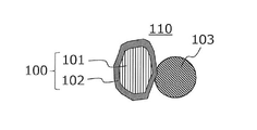
- FIG. 3 is a cross-sectional view showing a schematic configuration of a positive electrode material in Embodiment 2.
- FIG. 4 is a cross-sectional view showing a schematic configuration of a battery according to Embodiment 3.
- FIG. 1 is a cross-sectional view showing a schematic configuration of a composite positive electrode active material according to Embodiment 1.
- FIG. 3 is a cross-sectional view showing a schematic configuration of a positive electrode material in Embodiment 2.
- FIG. 4 is a cross-sectional view showing a schematic configuration of a battery according to Embodiment 3.
- Patent Document 1 a positive electrode active material is coated with a sulfide solid electrolyte.
- a sulfide solid electrolyte is a material with high ionic conductivity, but has a problem in oxidation resistance.
- Patent Document 2 uses a halide solid electrolyte containing chlorine and/or bromine. As a result of intensive studies, the present inventors have found that when the positive electrode material contains a halide solid electrolyte containing chlorine and/or bromine, the halide solid electrolyte is oxidatively decomposed during battery charging, and the battery is charged accordingly. It was found that the discharge efficiency decreased.
- the solid electrolyte when a solid electrolyte containing chlorine or bromine and a positive electrode active material having an average potential against Li of 3.7 V or more are used in combination, the solid electrolyte is decomposed by an oxidation reaction during charging, and the oxidative decomposition is performed.
- An object can act as a resistive layer.
- the oxidation reaction means a normal charging reaction in which lithium and electrons are extracted from the positive electrode active material in the positive electrode material, and a side reaction in which electrons are also extracted from the solid electrolyte in contact with the positive electrode active material.
- a resistance layer of oxidized decomposition products with poor lithium ion conductivity is formed between the positive electrode active material and the solid electrolyte, and this resistance layer is thought to function as a large interfacial resistance.
- the inventor studied a technique for suppressing the formation of a high resistance layer between the positive electrode active material and the solid electrolyte. As a result of examination, it was found that a battery using a positive electrode active material coated with a fluoride solid electrolyte exhibits excellent oxidation resistance and can suppress an increase in internal resistance of the battery during charging. Although the details of the mechanism are not clear, it is presumed to be as follows. Fluorine, which has the highest electronegativity among halogen elements, strongly bonds with cations in the fluoride solid electrolyte. As a result, the oxidation reaction of fluorine, that is, the side reaction in which electrons are extracted from fluorine, does not easily proceed. Therefore, fluoride solid electrolytes exhibit excellent oxidation resistance.
- the present inventor examined the thermal stability of the positive electrode active material coated with the fluoride solid electrolyte. As a result of investigation, it was found that when the positive electrode active material undergoes a heat history of 100° C. or more, the output resistance of the battery during discharge increases. Although the details of the mechanism are not clear, it is presumed to be as follows. As the positive electrode active material undergoes thermal history, moisture is generated from some of the water, hydrates, and hydroxides present in the positive electrode active material. Hydrogen fluoride is generated by reacting the generated moisture with the fluoride solid electrolyte. Furthermore, water is generated again by reacting hydrogen fluoride with the positive electrode active material. By repeating these reactions, a resistance layer is formed at the interface between the positive electrode active material and the fluoride solid electrolyte.
- the present inventors conducted extensive studies and found that by coating the positive electrode active material with a specific material, it is possible to suppress an increase in the output resistance of the battery when heat is applied.
- the composite positive electrode active material according to the first aspect of the present disclosure is a positive electrode active material; a coating layer that covers at least part of the surface of the positive electrode active material; with wherein the coating layer comprises a first coating material and a second coating material;
- the first coating material is a fluoride solid electrolyte
- the second coating material is a material that generates at least one selected from the group consisting of lithium oxide and lithium fluoride after reacting with at least one selected from the group consisting of water and hydrogen fluoride.
- the composite positive electrode active material according to the second aspect of the present disclosure is a positive electrode active material; a coating layer that covers at least part of the surface of the positive electrode active material; with wherein the coating layer contains Li, Ti, M, P, O and F; M is at least one selected from the group consisting of Ca, Mg, Al, Y and Zr.
- an increase in battery output resistance can be suppressed when heat is applied.
- the coating layer may include a first coating material and a second coating material, and the first coating material is Li , Ti, M, and F, and the second coating material may include Li, P, and O. According to such a configuration, the reaction between the coating material and water and the reaction between the coating material and hydrogen fluoride can be effectively suppressed.
- M may be Al. With such a configuration, the ionic conductivity of the coating material can be improved.
- ⁇ may satisfy 0.5 ⁇ 1. With such a configuration, the ionic conductivity of the coating material can be further improved.
- the second coating material may contain lithium phosphate.
- Li 3 PO 4 reacts with water and hydrogen fluoride to produce lithium oxide and fluoride to stop the ongoing reaction.
- the volume of the second coating material with respect to the volume of the first coating material may be in the range of 2% or more and less than 100%.
- the ratio is appropriately adjusted, the ionic conductivity of the coating material can be ensured while suppressing the continuous reaction mediated by the positive electrode active material, the fluoride solid electrolyte, water and hydrogen fluoride.
- the ratio may be in the range of 2% or more and 50% or less. According to such a configuration, it is possible to further suppress an increase in the output resistance of the battery.
- the ratio of the volume of the coating layer to the volume of the positive electrode active material is 1% or more and 10% It may be in the following range.
- the surface of the positive electrode active material is coated with an appropriate amount of coating material.
- the positive electrode active material may contain nickel-cobalt lithium aluminum oxide. With such a configuration, the energy density of the battery can be increased.
- the positive electrode material according to the thirteenth aspect of the present disclosure is a composite cathode active material of any one of the first to twelfth aspects; a first solid electrolyte; It has
- the composite positive electrode active material provides the desired effect to the positive electrode material.
- the first solid electrolyte may contain a halide solid electrolyte.
- Halide solid electrolytes have excellent oxidation resistance.
- the first solid electrolyte may contain a sulfide solid electrolyte.
- Sulfide solid electrolytes are excellent in ionic conductivity and flexibility.
- the battery according to the sixteenth aspect of the present disclosure includes a positive electrode comprising the positive electrode material of any one of the thirteenth to fifteenth aspects; a negative electrode; an electrolyte layer disposed between the positive electrode and the negative electrode; It has
- the positive electrode material includes the composite positive electrode active material of the present disclosure, the desired effect is brought to the battery.
- the electrolyte layer may contain a second solid electrolyte, and the second solid electrolyte is included in the first solid electrolyte A solid electrolyte having the same composition as that of the solid electrolyte may be included. According to such a configuration, it is possible to further improve the output characteristics of the battery.
- the electrolyte layer may contain a second solid electrolyte, and the second solid electrolyte is included in the first solid electrolyte
- a halide solid electrolyte having a composition different from that of the solid electrolyte may be included. According to such a configuration, it is possible to further improve the output characteristics of the battery.
- the electrolyte layer may contain a second solid electrolyte, and the second solid electrolyte may contain a sulfide solid electrolyte. good. If the electrolyte layer contains a sulfide solid electrolyte with excellent reduction stability, a negative electrode material with a low potential such as graphite or metallic lithium can be used for the negative electrode.
- a method for producing a composite positive electrode active material according to a twentieth aspect of the present disclosure includes: A method for producing a composite positive electrode active material according to any one of the first to twelfth aspects, comprising: The manufacturing method includes treating a mixture containing the positive electrode active material and the material constituting the coating layer by a dry particle compounding method, The dry particle compounding method involves imparting mechanical energy of impact, compression and shear to the mixture.
- the composite positive electrode active material of the present disclosure can be efficiently produced.
- FIG. 1 is a cross-sectional view showing a schematic configuration of a composite positive electrode active material according to Embodiment 1.
- FIG. Composite cathode active material 100 includes cathode active material 101 and coating layer 102 .
- the coating layer 102 covers at least part of the surface of the positive electrode active material 101 .
- Coating layer 102 includes a first coating material and a second coating material.
- the first coating material is a fluoride solid electrolyte.
- the second coating material is a material that produces at least one selected from the group consisting of lithium oxide and lithium fluoride after reacting with at least one selected from the group consisting of water and hydrogen fluoride.
- the material forming the coating layer 102 may be referred to as "coating material”.
- coating material we mean both the first coating material and the second coating material.
- a coating layer 102 is formed by placing the coating material on at least part of the surface of the positive electrode active material 101 . According to such a configuration, it is possible to suppress an increase in the output resistance of the battery when heat is applied.
- the coating layer 102 may contain Li, Ti, M, P, O and F.
- M is at least one selected from the group consisting of Ca, Mg, Al, Y and Zr. According to such a configuration, the composite positive electrode active material 100 can suppress an increase in battery output resistance when heat is applied.
- the coating layer 102 includes a first coating material and a second coating material.
- the first coating material contains Li, Ti, M, and F.
- the second coating material contains Li, P, and O.
- FIG. 2 is a diagram for explaining actions and effects of the composite positive electrode active material 100.
- FIG. 1 As shown in STEP 1, as shown in STEP 1, when heat is applied to the composite positive electrode active material 100, moisture (H 2 O) is generated from water, hydrates, and hydroxides present inside or on the surface of the positive electrode active material 101. .
- moisture H 2 O
- hydrogen fluoride HF
- LiMF 6 fluoride solid electrolyte
- formula (b) of STEP 3 hydrogen fluoride reacts with the positive electrode active material 101 to corrode or fluorinate the surface of the positive electrode active material 101 .
- hydrogen fluoride reacts with the positive electrode active material 101 (LiM'O x ) to generate water.
- a resistance layer is formed at the interface between the positive electrode active material 101 and the coating layer 102 .
- the resistive layer typically contains an oxyfluoride containing oxygen and fluorine as anions.
- the reaction of STEP2.1 occurs in competition with the reaction of STEP2. That is, as shown in formula (c) in STEP 2.1, a compound such as Li 3 PO 4 reacts with water to produce lithium oxide (Li 2 O) and stop the reaction. Moreover, the reaction of STEP3.1 occurs in competition with the reaction of STEP3. That is, as shown in formula (d) in STEP 3.1, a compound such as Li 3 PO 4 reacts with hydrogen fluoride to produce lithium fluoride (LiF) and stop the reaction. This prevents the formation of a resistive layer, thereby suppressing an increase in the output resistance of the battery when heat is applied.
- lithium hydrogen phosphate Li x H y PO 4
- lithium dihydrogen phosphate lithium dihydrogen phosphate
- phosphoric acids PO x H y
- the first coating material may be represented by the following compositional formula (1).
- M can be Al. With such a configuration, the ionic conductivity of the coating material can be improved.
- ⁇ may satisfy 0.5 ⁇ 1.
- the second coating material is a material that produces at least one selected from the group consisting of lithium oxide and lithium fluoride after reacting with at least one selected from the group consisting of water and hydrogen fluoride.
- the second coating material is typically a lithium-containing phosphate.
- Examples of the second coating material include Li 3 PO 4 , LiMe 2 (PO 4 ) 3 , LiFePO 4 , element-substituted products thereof, and the like.
- Me is at least one selected from the group consisting of Ti, Zr, Ge and Si. One or a mixture of two or more selected from these may be used as the second coating material.
- the second coating material is typically lithium phosphate ( Li3PO4 ). As described with reference to FIG. 2, Li 3 PO 4 reacts with water and hydrogen fluoride to produce lithium oxide and fluoride to stop the ongoing reaction.
- Li3PO4 lithium phosphate
- Coating material is not limited to materials that strictly satisfy the above compositional formula.
- the “coating material” also includes a material containing a trace amount of impurities in addition to the constituent elements represented by the composition formula.
- impurities contained in the coating layer 102 other than the constituent elements represented by the composition formula are 5 mass % or less of the entire coating layer 102 .
- the ratio of the total mass of impurities contained in the first coating material and the second coating material to the total mass of the coating layer 102 may be 5% or less, 3% or less, or 1% or less. It may be present, or may be 0.5% or less.
- the coating layer 102 may consist essentially of the first coating material and the second coating material, or may consist only of the first coating material and the second coating material.
- the phrase "consisting essentially of” shall mean excluding other ingredients that modify the essential characteristics of the referenced material.
- the phrase “consisting only of” means that no other ingredients other than unavoidable impurities are intentionally added.
- the first coating material and the second coating material may not contain sulfur. In this case, generation of hydrogen sulfide gas can be prevented.
- the ratio of the volume of the second coating material to the volume of the first coating material is, for example, in the range of 2% or more and less than 100%.
- the ratio is appropriately adjusted, the ionic conductivity of the coating material can be ensured while suppressing the continuous reaction mediated by the positive electrode active material, the fluoride solid electrolyte, water and hydrogen fluoride. This can effectively suppress the formation of a resistance layer between the positive electrode active material 101 and the coating layer 102, and thus suppress an increase in the output resistance of the battery when heat is applied.
- the ratio of the volume of the second coating material to the volume of the first coating material may be 50% or less.
- the ratio of the volume of the second coating material to the volume of the first coating material is an average value calculated from a large number of particles of the composite positive electrode active material 100.
- the ratio can be determined by the following method. For example, from the XPS spectrum of the composite positive electrode active material 100 by X-ray Photoelectron Spectroscopy (XPS), the element ratio of cations forming the coating layer 102 is calculated. From the element ratios, the respective molar ratios of the first coating material and the second coating material are calculated. The ratio of the volume of the second coating material to the volume of the first coating material can be calculated from the respective molar masses and densities of the first coating material and the second coating material.
- XPS X-ray Photoelectron Spectroscopy
- the ratio of the volume of the coating layer 102 to the volume of the positive electrode active material 101 is, for example, in the range of 1% or more and 10% or less.
- the surface of the positive electrode active material 101 is coated with an appropriate amount of coating material.
- formation of a resistance layer between the positive electrode active material 101 and the coating layer 102 can be effectively suppressed, and an increase in the output resistance of the battery can be suppressed.
- Transfer of electrons between particles of the positive electrode active material 101 is also smooth. This also contributes to suppressing an increase in battery output resistance.
- the volume ratio of the coating layer 102 to the volume of the positive electrode active material 101 can be specified by the following method. For example, from a cross-sectional SEM image of the composite positive electrode active material 100 obtained by a scanning electron microscope (SEM), the volume ratio is obtained for 20 arbitrarily selected materials, and the average value thereof can be obtained. can.
- the volume of the positive electrode active material 101 is defined as V1 and the volume of the composite positive electrode active material 100 is defined as V2
- the ratio of the volume (V2 ⁇ V1) of the coating layer 102 to the volume V1 of the positive electrode active material 101 is (V2 ⁇ V1)/V1.
- the volume V1 of the positive electrode active material 101 can be calculated by the following method.
- the area of the positive electrode active material 101 is calculated from the outline of the positive electrode active material 101 extracted from the cross-sectional SEM image.
- a radius (equivalent circle diameter) r1 of a circle having an area equivalent to this area is calculated.
- the volume V1 of the positive electrode active material 101 can be calculated from the equivalent circle diameter r1.
- the volume of the coating layer 102 can be calculated as a value obtained by subtracting the volume V1 of the positive electrode active material 101 from the volume V2 of the composite positive electrode active material 100 (V2 ⁇ V1).
- the volume V2 of the composite cathode active material 100 can be calculated by the following method.
- the average thickness of the coating layer 102 is added to the equivalent circle diameter r1 of the positive electrode active material 101 calculated from the cross-sectional SEM image, and this is regarded as the equivalent circle diameter r2 of the composite positive electrode active material 100 .
- volume V2 of composite positive electrode active material 100 can be calculated from equivalent circle diameter r2.
- the average thickness of the coating layer 102 for example, for 20 arbitrarily selected cross-sectional SEM images of the composite positive electrode active material 100, the thickness of the coating layer 102 at arbitrary 16 points on each particle is measured. It can be obtained by calculating the average value from the values.
- the covering layer 102 can be a single layer. According to such a configuration, the coating layer 102 can be easily formed, and an increase in manufacturing cost of the composite positive electrode active material 100 can be suppressed. Moreover, the desired effect can be obtained uniformly over the entire coating layer 102 .
- the coating layer 102 includes a mixture of a first coating material and a second coating material. With such a configuration, the desired effect can be obtained uniformly over the entire coating layer 102 .
- the coating layer 102 has a substantially uniform composition. That is, in the coating layer 102, the first coating material and the second coating material are uniformly mixed. With such a configuration, the desired effect can be obtained uniformly over the entire coating layer 102 .
- the coating layer 102 may be composed of multiple layers.
- the coating layer 102 can be formed by coating the surface of the positive electrode active material 101 with the second coating material and then coating the surface with the first coating material. That is, the coating layer 102 includes a first coating layer that coats at least part of the surface of the positive electrode active material 101 with the second coating material, and a first coating layer that covers at least part of the surface of the positive electrode active material 101 including the first coating layer. and a second coating layer coated with a coating material.
- the continuous reaction between the positive electrode active material, the fluoride solid electrolyte, water, and hydrogen fluoride can be efficiently carried out. can be suppressed to As a result, formation of a resistance layer at the interface between the positive electrode active material 101 and the coating layer 102 can be effectively suppressed, and an increase in the output resistance of the battery when heat is applied can be further suppressed.
- the thickness of the coating layer 102 is, for example, 1 nm or more and 300 nm or less.
- the thickness of the coating layer 102 can be measured by the methods previously described.
- the composite positive electrode active material 100 has, for example, a particle shape.
- the shape of the particles of the composite positive electrode active material 100 is not particularly limited.
- the shape of the particles of the composite positive electrode active material 100 is acicular, scale-like, spherical, or oval.
- the first coating material can be produced, for example, by the method described below.
- Raw material powders are prepared so that the compounding ratio of the desired composition is achieved.
- LiF , AlF3 and TiF4 are prepared in a molar ratio of 2.7 : 0.7 :0.3.
- the values " ⁇ ", " ⁇ ” and “ ⁇ ” in the above compositional formula (1) can be adjusted by adjusting the raw materials, compounding ratio and synthesis process.
- the mechanochemical milling method is used to mix, pulverize, and react the raw material powders.
- the mixture may be fired in a vacuum or in an inert atmosphere. For example, firing is performed at a temperature range of 100° C. to 800° C. for one hour or longer. This yields a first coating material having the composition described above.
- the configuration of the crystal phase (crystal structure) in the first coating material can be determined by adjusting the reaction method and reaction conditions between the raw material powders.
- the second coating material can be produced, for example, by the following method.
- Raw material powders are prepared so that the compounding ratio of the desired composition is obtained.
- Li 3 PO 4 Li 2 CO 3 and NH 4 H 2 PO 4 are prepared in a molar ratio of 3:2.
- Li 3 PO 4 as the second coating material.
- commercially available Li3PO4 reagents can also be used.
- composition of the crystal phase (crystal structure) in the second coating material can be determined by adjusting the reaction method and reaction conditions between the raw material powders.
- the coating material can be manufactured, for example, by the following method.
- a first coating material and a second coating material are prepared so as to have a desired volume ratio.
- Li 2.7 Al 0.7 Ti 0.3 F 6 is used as the first coating material and Li 3 PO 4 is used as the second coating material.
- Li 2.7 Al 0.7 Ti 0.3 F 6 and Li 3 PO 4 are prepared at a volume ratio of 1:1. By mixing these raw material powders, the intended coating material can be obtained.
- the composition of the coating material can be adjusted.
- the positive electrode active material 101 includes a material that has the property of intercalating and deintercalating metal ions (for example, lithium ions).
- the positive electrode active material 101 include lithium-containing transition metal oxides, transition metal fluorides, polyanion materials, fluorinated polyanion materials, transition metal sulfides, transition metal oxysulfides, and transition metal oxynitrides.
- Lithium-containing transition metal oxides include Li(Ni, Co, Al) O 2 , Li(Ni, Co, Mn) O 2 and LiCoO 2 .
- the positive electrode active material 101 may be lithium nickel cobalt aluminum oxide.
- the positive electrode active material 101 may be Li(Ni, Co, Al) O 2 .
- a positive electrode active material provided with a coating containing lithium metal oxide on the surface thereof may be used. That is, a coating made of lithium metal oxide may be provided between the positive electrode active material 101 and the coating layer 102 .
- lithium metal oxides include LiNbO 3 (lithium niobate).
- the positive electrode active material 101 has, for example, a particle shape.
- the shape of the particles of the positive electrode active material 101 is not particularly limited.
- the shape of the particles of the positive electrode active material 101 can be spherical, oval, scaly, or fibrous.
- the composite cathode active material 100 can be produced, for example, by the following method.
- a mixture is obtained by mixing the powder of the positive electrode active material 101 and the powder of the coating material in an appropriate ratio.
- the mixture is milled and mechanical energy is imparted to the mixture.
- a mixing device such as a ball mill can be used for the milling treatment.
- the milling process may be performed in a dry and inert atmosphere to suppress oxidation of the material.
- the composite positive electrode active material 100 may be produced by a dry particle compounding method. Processing by the dry particle compounding method involves agitating while imparting mechanical energy of impact, compression and shear to the mixture containing the cathode active material 101 and the coating material. According to the dry particle compounding method, the composite positive electrode active material 100 can be produced efficiently.
- the device used in the coating process is not particularly limited, and can be a device that can apply mechanical energy such as impact, compression, shear, etc. to the mixture.
- Apparatuses capable of imparting mechanical energy include compression shear processing apparatuses (particle compounding apparatuses) such as ball mills, "Mechanofusion” (manufactured by Hosokawa Micron Corporation), and “Nobiruta” (manufactured by Hosokawa Micron Corporation).
- compression shear processing apparatuses particle compounding apparatuses
- Mechanofusion manufactured by Hosokawa Micron Corporation
- Niobiruta manufactured by Hosokawa Micron Corporation
- Mechanism is a particle compounding device that uses dry mechanical compounding technology by applying strong mechanical energy to multiple different material particles.
- particles are combined by applying mechanical energy such as compression, shear, and friction to raw material powder put between a rotating container and a press head.
- Nobilta is a particle compounding device that uses dry mechanical compounding technology, which is an advanced form of particle compounding technology, in order to compound nanoparticles from raw materials.
- Nobilta employs a technology to produce composite particles by applying mechanical energy such as impact, compression and shear to multiple raw material powders.
- the rotor which is arranged in a horizontal cylindrical mixing vessel with a predetermined gap between it and the inner wall of the mixing vessel, rotates at high speed, forcing the raw material particles to pass through the gap. This process is repeated multiple times. Thereby, composite particles of the positive electrode active material 101 and the coating material can be produced by applying impact, compression, and shear forces to the mixture. Conditions such as the rotational speed of the rotor, the treatment time, and the charge amount can be adjusted as appropriate.
- the types and amounts of elements contained in the composite positive electrode active material 100 can be identified by known chemical analysis methods.
- FIG. 3 is a cross-sectional view showing a schematic configuration of a positive electrode material in Embodiment 2.
- the positive electrode material 110 includes the composite positive electrode active material 100 of Embodiment 1 and the first solid electrolyte 103 .
- Composite positive electrode active material 100 provides positive electrode material 110 with the effects described in the first embodiment.
- the first solid electrolyte 103 may contain a halide solid electrolyte.
- Halide solid electrolytes have excellent oxidation resistance. Examples of halide solid electrolytes include Li 3 (Ca, Y, Gd) X 6 , Li 2 MgX 4 , Li 2 FeX 4 , Li (Al, Ga, In) X 4 , Li 3 (Al, Ga, In) X 6 , LiI, and the like.
- X is at least one selected from the group consisting of Cl, Br and I;
- an element in a formula is expressed as "(Al, Ga, In)"
- this notation indicates at least one element selected from the parenthesized group of elements. That is, "(Al, Ga, In)" is synonymous with "at least one selected from the group consisting of Al, Ga, and In.”
- the halide solid electrolyte may be free of sulfur.
- the first solid electrolyte 103 may contain a sulfide solid electrolyte.
- sulfide solid electrolytes include Li 2 SP 2 S 5 , Li 2 S—SiS 2 , Li 2 S—B 2 S 3 , Li 2 S—GeS 2 , Li 3.25 Ge 0.25 P 0.75 S 4 , Li10GeP2S12 and the like can be used.
- LiX , Li2O , MOq , LipMOq , etc. may be added to these.
- X is at least one selected from the group consisting of F, Cl, Br and I.
- the element M in "MO q " and “Li p MO q” is at least one selected from the group consisting of P, Si, Ge, B, Al, Ga, In, Fe, and Zn.
- p and q in "MO q " and “L p MO q " are independent natural numbers.
- the first solid electrolyte 103 may contain a sulfide solid electrolyte.
- Sulfide solid electrolytes are excellent in ionic conductivity and flexibility.
- the sulfide solid electrolyte may contain lithium sulfide and phosphorus sulfide.
- the sulfide solid electrolyte may be Li 2 SP 2 S 5 .
- the first solid electrolyte 103 has, for example, a particle shape.
- the shape of the particles of the first solid electrolyte 103 is not particularly limited.
- the shape of the particles of the first solid electrolyte 103 may be spherical, oval, scaly, or fibrous.
- the median diameter may be 100 ⁇ m or less.
- the composite positive electrode active material 100 and the first solid electrolyte 103 can form a good dispersion state in the positive electrode material 110 . This improves the charge/discharge characteristics of the battery.
- the median diameter of the first solid electrolyte 103 may be 10 ⁇ m or less.
- the median diameter of the first solid electrolyte 103 may be smaller than the median diameter of the composite cathode active material 100 . According to such a configuration, the composite positive electrode active material 100 and the first solid electrolyte 103 can form a good dispersion state in the positive electrode material 110 .
- the median diameter of the composite positive electrode active material 100 may be 0.1 ⁇ m or more and 100 ⁇ m or less.
- the median diameter of the composite positive electrode active material 100 is 0.1 ⁇ m or more, the composite positive electrode active material 100 and the first solid electrolyte 103 are easily dispersed in the positive electrode material 110 .
- the charge/discharge characteristics of the battery are improved.
- the median diameter of the composite positive electrode active material 100 is 100 ⁇ m or less, the diffusion rate of lithium inside the positive electrode active material 101 is sufficiently high. Therefore, the battery can operate at high output.
- the median diameter of the composite positive electrode active material 100 may be larger than the median diameter of the first solid electrolyte 103 . This allows the composite positive electrode active material 100 and the first solid electrolyte 103 to form a good dispersed state.
- volume diameter means the particle diameter when the cumulative volume in the volume-based particle size distribution is equal to 50%.
- the volume-based particle size distribution is measured by, for example, a laser diffraction measurement device or an image analysis device.
- the first solid electrolyte 103 and the composite positive electrode active material 100 may be in contact with each other.
- the coating layer 102 and the first solid electrolyte 103 are also in contact with each other. Particles of the first solid electrolyte 103 may fill spaces between the particles of the composite cathode active material 100 .
- the positive electrode material 110 may contain a plurality of first solid electrolyte 103 particles and a plurality of composite positive electrode active material 100 particles.
- the content of the first solid electrolyte 103 and the content of the composite positive electrode active material 100 may be the same or different.
- FIG. 4 is a cross-sectional view showing a schematic configuration of a battery according to Embodiment 3.
- FIG. 4 is a cross-sectional view showing a schematic configuration of a battery according to Embodiment 3.
- a battery 200 includes a positive electrode 201 , an electrolyte layer 202 and a negative electrode 203 .
- the electrolyte layer 202 is arranged between the positive electrode 201 and the negative electrode 203 .
- the positive electrode 201 contains the positive electrode material 110 described in the second embodiment. Since the positive electrode material 110 contains the composite positive electrode active material 100, the battery 200 has the effects described in the first embodiment.
- the volume of the positive electrode active material 101 is defined as v1.
- the total volume of coating layer 102 and first solid electrolyte 103 is defined as (100-v1).
- a volume v1 represents the volume of the positive electrode active material 101 when the total volume of the positive electrode active material 101, the coating layer 102 and the first solid electrolyte 103 is defined as 100.
- the ratio of the volume v1 and the total volume (100-v1) is defined as "v1:100-v1”
- 30 ⁇ v1 ⁇ 95 may be satisfied.
- the energy density of battery 200 is likely to be ensured.
- v1 ⁇ 95 the battery 200 can operate at high power.
- the thickness of the positive electrode 201 may be 10 ⁇ m or more and 500 ⁇ m or less. When the thickness of the positive electrode 201 is 10 ⁇ m or more, the energy density of the battery 200 is sufficiently ensured. When the thickness of the positive electrode 201 is 500 ⁇ m or less, the battery 200 can operate at high output.
- the electrolyte layer 202 is a layer containing an electrolyte.
- the electrolyte is, for example, a solid electrolyte. That is, electrolyte layer 202 may be a solid electrolyte layer.
- the solid electrolyte included in the electrolyte layer 202 may be referred to as "second solid electrolyte".
- At least one selected from the group consisting of halide solid electrolytes, sulfide solid electrolytes, oxide solid electrolytes, polymer solid electrolytes, and complex hydride solid electrolytes can be used as the second solid electrolyte.
- the second solid electrolyte may contain a solid electrolyte having the same composition as that of the solid electrolyte contained in the first solid electrolyte 103 .
- the second solid electrolyte may contain a halide solid electrolyte having the same composition as the halide solid electrolyte contained in the first solid electrolyte 103 .
- the electrolyte layer 202 may contain a halide solid electrolyte having the same composition as the halide solid electrolyte contained in the first solid electrolyte 103 .
- the second solid electrolyte may contain a halide solid electrolyte having a composition different from that of the halide solid electrolyte contained in the first solid electrolyte 103 . That is, the electrolyte layer 202 may contain a halide solid electrolyte having a composition different from that of the halide solid electrolyte contained in the first solid electrolyte 103 . With such a configuration, the output characteristics of the battery 200 can be further improved.
- the second solid electrolyte may contain a sulfide solid electrolyte.
- the second solid electrolyte may contain a sulfide solid electrolyte having the same composition as the sulfide solid electrolyte contained in the first solid electrolyte 103 . That is, the electrolyte layer 202 may contain a sulfide solid electrolyte having the same composition as the sulfide solid electrolyte contained in the first solid electrolyte 103 .
- a low-potential negative electrode material such as graphite or metallic lithium can be used for the negative electrode 203 .
- the energy density of the battery 200 can be improved.
- the electrolyte layer 202 contains a sulfide solid electrolyte having the same composition as the sulfide solid electrolyte contained in the first solid electrolyte 103, the output characteristics of the battery 200 can be further improved.
- the second solid electrolyte may contain an oxide solid electrolyte.
- oxide solid electrolytes include NASICON solid electrolytes typified by LiTi 2 (PO 4 ) 3 and element-substituted products thereof, (LaLi)TiO 3 -based perovskite solid electrolytes, Li 14 ZnGe 4 O 16 , Li LISICON solid electrolytes typified by 4 SiO 4 , LiGeO 4 and elemental substitutions thereof, garnet type solid electrolytes typified by Li 7 La 3 Zr 2 O 12 and elemental substitutions thereof, Li 3 PO 4 and its N Glass or glass-ceramics obtained by adding materials such as Li 2 SO 4 and Li 2 CO 3 to a base material containing a Li—BO compound such as LiBO 2 and Li 3 BO 3 may be used.
- the second solid electrolyte may contain a polymer solid electrolyte.
- a polymer solid electrolyte for example, a compound of a polymer compound and a lithium salt can be used.
- the polymer compound may have an ethylene oxide structure.
- a polymer compound having an ethylene oxide structure can contain a large amount of lithium salt. Therefore, the ionic conductivity can be further enhanced.
- Lithium salts include LiPF6 , LiBF4 , LiSbF6 , LiAsF6 , LiSO3CF3 , LiN ( SO2F ) 2 , LiN ( SO2CF3 ) 2 , LiN ( SO2C2F5 ) 2 , LiN( SO2CF3 )( SO2C4F9 ) , LiC ( SO2CF3 ) 3 etc. are mentioned.
- One lithium salt selected from these may be used alone, or a mixture of two or more lithium salts selected from these may be used.
- the second solid electrolyte may contain a complex hydride solid electrolyte.
- a complex hydride solid electrolyte for example, LiBH 4 --LiI, LiBH 4 --P 2 S 5 or the like can be used.
- the electrolyte layer 202 may contain the second solid electrolyte as a main component. That is, the electrolyte layer 202 may contain 50% or more (that is, 50% or more by mass) of the second solid electrolyte in terms of mass ratio with respect to the total mass of the electrolyte layer 202 . With such a configuration, the output characteristics of the battery 200 can be further improved.
- the electrolyte layer 202 may contain the second solid electrolyte at a mass ratio of 70% or more (that is, 70% by mass or more) with respect to the total mass of the electrolyte layer 202 . With such a configuration, the output characteristics of the battery 200 can be further improved.
- the electrolyte layer 202 contains the second solid electrolyte as a main component, and also contains unavoidable impurities, starting materials, by-products, decomposition products, etc. used when synthesizing the second solid electrolyte. You can
- the electrolyte layer 202 may contain 100% (that is, 100% by mass) of the second solid electrolyte with respect to the total mass of the electrolyte layer 202, excluding inevitable impurities. With such a configuration, the output characteristics of the battery 200 can be further improved.
- the electrolyte layer 202 may consist only of the second solid electrolyte.
- the electrolyte layer 202 may contain only one solid electrolyte selected from the group of solid electrolytes described above, or may contain two or more solid electrolytes selected from the group of solid electrolytes described above. .
- a plurality of solid electrolytes have compositions different from each other.
- electrolyte layer 202 may include a halide solid electrolyte and a sulfide solid electrolyte.
- the thickness of the electrolyte layer 202 may be 1 ⁇ m or more and 300 ⁇ m or less. When the thickness of the electrolyte layer 202 is 1 ⁇ m or more, the positive electrode 201 and the negative electrode 203 can be reliably separated. When the thickness of the electrolyte layer 202 is 300 ⁇ m or less, the battery 200 can operate at high output. If the thickness of the electrolyte layer 202 is appropriately adjusted, both safety and output characteristics can be achieved.
- the negative electrode 203 includes a material that has the property of intercalating and deintercalating metal ions (eg, lithium ions).
- the negative electrode 203 contains, for example, a negative electrode active material.
- Metal materials, carbon materials, oxides, nitrides, tin compounds, silicon compounds, etc. can be used for the negative electrode active material.
- the metal material may be a single metal or an alloy.
- metal materials include lithium metal and lithium alloys.
- Examples of carbon materials include natural graphite, coke, ungraphitized carbon, carbon fiber, spherical carbon, artificial graphite, and amorphous carbon. In terms of capacity density, silicon (Si), tin (Sn), silicon compounds, or tin compounds can be used.
- the negative electrode 203 may contain a solid electrolyte (third solid electrolyte). With such a configuration, the lithium ion conductivity inside the negative electrode 203 is increased, so that the battery 200 can operate at high output.
- the third solid electrolyte the materials given as examples of the second solid electrolyte can be used.
- the median diameter of the particles of the negative electrode active material may be larger than the median diameter of the particles of the third solid electrolyte contained in the negative electrode 203 . Thereby, a favorable dispersion state of the negative electrode active material and the third solid electrolyte can be formed.
- the volume of the negative electrode active material is defined as v2.
- the volume of the third solid electrolyte is defined as (100-v2).
- the volume v2 represents the volume of the negative electrode active material when the total volume of the negative electrode active material and the third solid electrolyte is defined as 100.
- the ratio of volume v2 and volume (100-v2) is defined as "v2:100-v2”
- 30 ⁇ v2 ⁇ 95 may be satisfied.
- the energy density of battery 200 is likely to be ensured.
- v2 ⁇ 95 the battery 200 can operate at high power.
- the thickness of the negative electrode 203 may be 10 ⁇ m or more and 500 ⁇ m or less. When the thickness of the negative electrode 203 is 10 ⁇ m or more, the energy density of the battery 200 is sufficiently ensured. When the thickness of the negative electrode 203 is 500 ⁇ m or less, the battery 200 can operate at high power.
- At least one selected from the group consisting of the positive electrode 201, the electrolyte layer 202 and the negative electrode 203 may contain a binder for the purpose of improving adhesion between particles.
- a binder is used to improve the binding properties of the material that constitutes the electrode.
- Binders include polyvinylidene fluoride, polytetrafluoroethylene, polyethylene, polypropylene, aramid resin, polyamide, polyimide, polyamideimide, polyacrylonitrile, polyacrylic acid, polyacrylic acid methyl ester, polyacrylic acid ethyl ester, poly Acrylate hexyl ester, polymethacrylic acid, polymethacrylic acid methyl ester, polymethacrylic acid ethyl ester, polymethacrylic acid hexyl ester, polyvinyl acetate, polyvinylpyrrolidone, polyether, polyethersulfone, hexafluoropolypropylene, styrene-butadiene rubber, Carboxymethyl cellulose etc.
- Binders include tetrafluoroethylene, hexafluoroethylene, hexafluoropropylene, perfluoroalkyl vinyl ether, vinylidene fluoride, chlorotrifluoroethylene, ethylene, propylene, pentafluoropropylene, fluoromethyl vinyl ether, acrylic acid, and Copolymers of two or more materials selected from the group consisting of hexadiene can be used. Also, two or more selected from these may be mixed and used as a binder.
- At least one of the positive electrode 201 and the negative electrode 203 may contain a conductive aid for the purpose of increasing electronic conductivity.
- conductive aids include graphites such as natural graphite and artificial graphite; carbon blacks such as acetylene black and ketjen black; conductive fibers such as carbon fiber and metal fiber; carbon fluoride; metal powders such as aluminum; Conductive whiskers such as zinc oxide and potassium titanate; conductive metal oxides such as titanium oxide; and conductive polymer compounds such as polyaniline, polypyrrole and polythiophene.
- the battery 200 can be configured as a battery of various shapes such as coin type, cylindrical type, square type, sheet type, button type, flat type, and laminated type.
- the battery 200 can be manufactured by the following method. First, the positive electrode material 110, the material for forming the electrolyte layer 202, and the material for forming the negative electrode 203 are prepared. A laminate in which the positive electrode 201, the electrolyte layer 202, and the negative electrode 203 are arranged in this order is produced by a known method. Thereby, the battery 200 is obtained.
- LTAF Li 2.7 Al 0.7 Ti 0.3 F 6
- LPO Li 3 PO 4
- solvent an appropriate amount of solvent
- the average particle size of the coating material was calculated from a planar SEM image of the coating material obtained by a scanning electron microscope (manufactured by Keyence Corporation, 3D Real Surface View Microscope, VE-8800, magnification of 5000). Specifically, the average value of the circle-equivalent diameters of 50 arbitrarily selected particles in the planar SEM image of the coating material was calculated as the average particle diameter.
- Li(NiCoAl)O 2 Li(NiCoAl)O 2 (hereinafter referred to as NCA) having an average particle size of 5 ⁇ m was used as the positive electrode active material.
- the positive electrode active material was coated with the coating material A using a particle compounding device (Nobilta, NOB-MINI, manufactured by Hosokawa Micron Corporation). 49.1 g of NCA and 0.9 g of Coating Material A were placed in a NOB-MINI container. The NCA and the coating material A were composited under the conditions of a rotation speed of 6000 rpm, an operation time of 60 minutes, and a power value of 550 W to 740 W. As a result, composite positive electrode active materials of Samples 1 to 3 were obtained. The ratio of the volume of the coating material A to the volume of the positive electrode active material was 3% by volume.
- Coating material B was made in the same manner as sample 1, except that the volume ratio of LPO to LTAF was changed to 1:1.
- NCA and 1.2 g of coating material B were placed in the NOB-MINI container.
- the NCA and the coating material B were composited under the conditions of a rotation speed of 6000 rpm, an operation time of 60 minutes, and a power value of 550 W to 740 W. In this way, composite positive electrode active materials of Samples 4 to 6 were produced.
- the volume ratio of the coating material B to the volume of the positive electrode active material was 4% by volume.
- Coating material C was made in the same manner as sample 1, except that the volume ratio of LPO to LTAF was changed to 2:98.
- NCA and 3.2 g of coating material C were placed in the NOB-MINI container.
- the NCA and the coating material C were compounded under the conditions of a rotation speed of 6000 rpm, an operation time of 60 minutes, and a power value of 550 W to 740 W. In this way, composite positive electrode active materials of samples 7 to 9 were produced.
- the volume ratio of the coating material C to the volume of the positive electrode active material was 10% by volume.
- sample D As coating material D, the LTAF powder used in sample 1 was prepared.
- NCA and 0.6 g of coating material D were placed in the NOB-MINI container.
- the NCA and the coating material D were combined under the conditions of a rotation speed of 6000 rpm, an operation time of 60 minutes, and a power value of 550 W to 740 W.
- samples 10 to 12 of composite positive electrode active materials were produced.
- the ratio of the volume of the coating material D to the volume of the positive electrode active material was 2% by volume.
- the heat treatment process was performed in the same manner as samples 1 to 3.
- the heat treatment temperature was 100° C. for sample 10, 200° C. for sample 11, and 300° C. for sample 12.
- the heat-treated powder was re-pulverized in an agate mortar. As a result, samples 10 to 12 of composite positive electrode active materials (heat-treated) were obtained.
- NCA and 3.2 g of coating material D were placed in the NOB-MINI container.
- the NCA and the coating material D were combined under the conditions of a rotation speed of 6000 rpm, an operation time of 60 minutes, and a power value of 550 W to 740 W. In this way, samples 13 to 15 of composite positive electrode active materials were produced.
- the volume ratio of the coating material D to the volume of the positive electrode active material was 10% by volume.
- sample 16 A composite positive electrode active material of sample 16 was prepared in the same manner as sample 1, except that the composite positive electrode active material was not heat-treated.
- sample 17 A composite positive electrode active material of sample 17 was prepared in the same manner as sample 4, except that the composite positive electrode active material was not heat-treated.
- sample 18 A composite positive electrode active material of sample 18 was produced in the same manner as sample 7, except that the composite positive electrode active material was not heat-treated.
- sample 19 A composite positive electrode active material of sample 19 was prepared in the same manner as sample 10, except that the composite positive electrode active material was not heat-treated.
- sample 20 A composite positive electrode active material of sample 20 was prepared in the same manner as sample 13, except that the composite positive electrode active material was not heat-treated.
- Li 2 SP 2 S 5 60 mg was placed in an insulating outer cylinder and pressure-molded at a pressure of 80 MPa to form an electrolyte layer.
- 15.6 mg of the positive electrode material of Sample 1 in terms of the mass of the positive electrode active material was placed in an insulating outer cylinder and pressure-molded at a pressure of 720 MPa.
- metal Li thinness: 200 ⁇ m
- a laminate of the positive electrode, the electrolyte layer and the metal Li was pressure-molded at a pressure of 80 MPa to form a negative electrode.
- stainless steel collectors were placed above and below the laminate, and collector leads were attached to the collectors.
- the insulating outer cylinder was sealed with an insulating ferrule so that the inside of the insulating outer cylinder was isolated from the atmosphere. Through these steps, a sample 1 battery was obtained.
- the inner diameter of the insulating outer cylinder was 9.5 mm, and the projected area of the electrode was 0.71 cm 2 .
- the battery was placed in a constant temperature bath at 25°C.
- Constant current charging was performed at a current value of 319 ⁇ A, which is 0.1 C rate (10 hour rate) with respect to the theoretical capacity of the battery, and charging was terminated at a voltage of 4.3 V (voltage based on Li/Li + ).
- constant-voltage charging was performed at a voltage of 4.3 V, and charging was terminated when the current value fell below 31.9 ⁇ A, which is the 0.01 C rate.
- constant current discharge was performed at a current value of 319 ⁇ A, which is a 0.1 C rate, and the discharge was terminated at a voltage of 3.62 V (voltage based on Li/Li + ).
- the output resistance of the batteries of samples 1 to 3 was lower than that of the batteries of samples 10 to 12.
- the output resistance of the batteries of samples 4-6 was also lower than that of the batteries of samples 10-12.
- the output resistance of the batteries of samples 3 and 6 was lower than the output resistance of sample 12 when the samples that underwent a thermal history of 300° C. or higher were compared with each other.
- the output resistance of the batteries of Samples 7 to 9 was lower than that of the batteries of Samples 13 to 15.
- the ratio of the volume of LPO, which is the second coating material, to the volume of LTAF, which is the first coating material is 2% or more and less than 100% (more precisely, the ratio of LPO to the total volume of LPO and LTAF)
- the volume ratio was in the range of 2% or more and 50% or less, it was possible to sufficiently suppress the increase in the output resistance of the battery when heat was applied.
- the output resistance of the cells decreased slightly as the volume fraction of LPO increased.
- the ratio of the volume of LPO to the volume of LTAF may be 50% or less.
- the ratio of the volume of the coating layer to the volume of the positive electrode active material was in the range of 1% or more and 10% or less, it was possible to sufficiently suppress the increase in the output resistance of the battery when heat was applied.
- LTMF fluoride solid electrolyte
- the technology of the present disclosure is useful for batteries such as all-solid lithium secondary batteries.
- composite positive electrode active material 101 positive electrode active material 102 coating layer 103 first solid electrolyte 110 positive electrode material 200 battery 201 positive electrode 202 electrolyte layer 203 negative electrode
Landscapes
- Chemical & Material Sciences (AREA)
- General Chemical & Material Sciences (AREA)
- Chemical Kinetics & Catalysis (AREA)
- Electrochemistry (AREA)
- Engineering & Computer Science (AREA)
- Inorganic Chemistry (AREA)
- Manufacturing & Machinery (AREA)
- Composite Materials (AREA)
- General Physics & Mathematics (AREA)
- Condensed Matter Physics & Semiconductors (AREA)
- Physics & Mathematics (AREA)
- Materials Engineering (AREA)
- Battery Electrode And Active Subsutance (AREA)
Abstract
Description
正極活物質と、
前記正極活物質の表面の少なくとも一部を被覆する被覆層と、
を備え、
ここで、前記被覆層は、フッ化物固体電解質を含む第1被覆材料と、第2被覆材料と、を含み、
前記第2被覆材料は、水およびフッ化水素からなる群より選択される少なくとも1つと反応後、酸化リチウムおよびフッ化リチウムからなる群より選択される少なくとも1つを生成する材料である、
複合正極活物質を提供する。
特許文献1では、正極活物質が硫化物固体電解質で被覆されている。硫化物固体電解質は、イオン伝導度の高い材料であるが、酸化耐性に課題がある。
本開示の第1態様に係る複合正極活物質は、
正極活物質と、
前記正極活物質の表面の少なくとも一部を被覆する被覆層と、
を備え、
ここで、前記被覆層は、第1被覆材料および第2被覆材料を含み、
前記第1被覆材料は、フッ化物固体電解質であり、
前記第2被覆材料は、水およびフッ化水素からなる群より選択される少なくとも1つと反応後、酸化リチウムおよびフッ化リチウムからなる群より選択される少なくとも1つを生成する材料である。
正極活物質と、
前記正極活物質の表面の少なくとも一部を被覆する被覆層と、
を備え、
ここで、前記被覆層は、Li、Ti、M、P、OおよびFを含み、
Mは、Ca、Mg、Al、Y、およびZrからなる群より選択される少なくとも1つである。
LiαTiβMγF6・・・式(1)
第1から第12態様のいずれか1つの複合正極活物質と、
第1固体電解質と、
を備えている。
第13から第15態様のいずれか1つの正極材料を含む正極と、
負極と、
前記正極と前記負極との間に配置された電解質層と、
を備えている。
第1から第12態様のいずれか1つの複合正極活物質の製造方法であって、
前記製造方法は、前記正極活物質と前記被覆層を構成する材料とを含む混合物を乾式粒子複合化法によって処理することを含み、
前記乾式粒子複合化法は、衝撃、圧縮、およびせん断の機械的エネルギーを前記混合物に付与することを含む。
(複合正極活物質)
図1は、実施の形態1における複合正極活物質の概略構成を示す断面図である。複合正極活物質100は、正極活物質101および被覆層102を備えている。被覆層102は、正極活物質101の表面の少なくとも一部を被覆している。被覆層102は、第1被覆材料および第2被覆材料を含む。第1被覆材料は、フッ化物固体電解質である。第2被覆材料は、水およびフッ化水素からなる群より選択される少なくとも1つと反応後、酸化リチウムおよびフッ化リチウムからなる群より選択される少なくとも1つを生成する材料である。本明細書では、被覆層102を構成する材料を「被覆材料」と称することがある。単に「被覆材料」と述べた場合、第1被覆材料および第2被覆材料の両者を意味する。被覆材料が正極活物質101の表面の少なくとも一部に位置することによって被覆層102が形成されている。このような構成によれば、熱が加わったときの電池の出力抵抗の上昇を抑制できる。
第1被覆材料は、例えば、下記の方法によって製造されうる。
正極活物質101は、金属イオン(例えば、リチウムイオン)を吸蔵および放出する特性を有する材料を含む。正極活物質101として、リチウム含有遷移金属酸化物、遷移金属フッ化物、ポリアニオン材料、フッ素化ポリアニオン材料、遷移金属硫化物、遷移金属オキシ硫化物、遷移金属オキシ窒化物などが挙げられる。リチウム含有遷移金属酸化物としては、Li(Ni,Co,Al)O2、Li(Ni,Co,Mn)O2、LiCoO2などが挙げられる。正極活物質101としてリチウム含有遷移金属酸化物を用いた場合、正極の製造コストを安くできるとともに、電池の平均放電電圧を高めることができる。
複合正極活物質100は、例えば、下記の方法によって製造されうる。
(正極材料)
図3は、実施の形態2における正極材料の概略構成を示す断面図である。
以下、実施の形態3が説明される。上述の実施の形態1および2と重複する説明は、適宜、省略される。
[被覆材料Aの作製]
露点-60℃以下、酸素値5ppm以下のアルゴン雰囲気のグローブボックス内で、原料粉末のLiF、AlF3およびTiF4をLiF:AlF3:TiF4=2.7:0.7:0.3のモル比となるように秤量した。これらの原料粉末をメノウ乳鉢で混合して混合物を得た。次に、遊星型ボールミル装置(フリッチュ社製、P‐7型)を用い、12時間、500rpmの条件で混合物をミリング処理した。これにより、Li2.7Al0.7Ti0.3F6(以下、LTAFと表記する)の組成式で表される合成物を得た。合成物と適量の溶媒とを混合し、遊星型ボールミル装置を用い、20分、200rpmの条件で合成物をミリング処理した。その後、溶媒を乾燥により除去した。これにより、第1被覆材料としての平均粒径0.5μmのLTAFの粉末を得た。
正極活物質として、平均粒径5μmのLi(NiCoAl)O2(以下、NCAと表記する)を用いた。
正極活物質への被覆材料Aの被覆は、粒子複合化装置(ノビルタ、NOB‐MINI、ホソカワミクロン社製)を用いて行った。NOB‐MINIの容器内に49.1gのNCAおよび0.9gの被覆材料Aを入れた。回転数6000rpm、作動時間60分、電力値550Wから740Wの条件で、NCAと被覆材料Aとを複合化した。これにより、サンプル1から3の複合正極活物質を得た。正極活物質の体積に対する被覆材料Aの体積の比率は3体積%であった。
サンプル1から3の複合正極活物質を用い、下記の熱処理工程を実施した。露点-60℃以下、酸素値5ppm以下のアルゴン雰囲気のグローブボックス内で複合正極活物質の粉末をアルミナ製るつぼに入れた。次に、るつぼを電気炉に入れ、複合正極活物質の熱処理を1時間かけて行った。熱処理温度は、サンプル1で100℃、サンプル2で200℃、サンプル3で300℃であった。熱処理後の粉末をメノウ乳鉢にて再粉砕した。これにより、サンプル1から3の複合正極活物質(熱処理済み)を得た。
LPOとLTAFとの体積比率を1:1に変更したことを除き、サンプル1と同じ方法で被覆材料Bを作製した。
LPOとLTAFとの体積比率を2:98に変更したことを除き、サンプル1と同じ方法で被覆材料Cを作製した。
被覆材料Dとして、サンプル1で用いたLTAFの粉末を用意した。
被覆材料Dとして、サンプル1で用いたLTAFの粉末を用意した。
複合正極活物質の熱処理を行わなかったことを除き、サンプル1と同じ方法でサンプル16の複合正極活物質を作製した。
複合正極活物質の熱処理を行わなかったことを除き、サンプル4と同じ方法でサンプル17の複合正極活物質を作製した。
複合正極活物質の熱処理を行わなかったことを除き、サンプル7と同じ方法でサンプル18の複合正極活物質を作製した。
複合正極活物質の熱処理を行わなかったことを除き、サンプル10と同じ方法でサンプル19の複合正極活物質を作製した。
複合正極活物質の熱処理を行わなかったことを除き、サンプル13と同じ方法でサンプル20の複合正極活物質を作製した。
サンプル1の複合正極活物質を用い、下記の工程を実施した。露点-60℃以下、酸素値5ppm以下のアルゴン雰囲気のグローブボックス内で、複合正極活物質とLi2S‐P2S5とを秤量した。複合正極活物質およびLi2S‐P2S5の量は、体積比率にて(正極活物質):(被覆材料+Li2S‐P2S5)=75:25の関係が満たされるように調整した。さらに、導電助剤(VGCF-H、昭和電工社製)を正極活物質の質量に対して1.5質量%になるように秤量した。これらをメノウ乳鉢で混合した。これにより、サンプル1の正極材料を作製した。「VGCF」は、昭和電工社の登録商標である。
以下の条件にて、サンプル1から20の電池を評価した。

101 正極活物質
102 被覆層
103 第1固体電解質
110 正極材料
200 電池
201 正極
202 電解質層
203 負極
Claims (20)
- 正極活物質と、
前記正極活物質の表面の少なくとも一部を被覆する被覆層と、
を備え、
ここで、前記被覆層は、第1被覆材料および第2被覆材料を含み、
前記第1被覆材料は、フッ化物固体電解質であり、
前記第2被覆材料は、水およびフッ化水素からなる群より選択される少なくとも1つと反応後、酸化リチウムおよびフッ化リチウムからなる群より選択される少なくとも1つを生成する材料である、
複合正極活物質。 - 正極活物質と、
前記正極活物質の表面の少なくとも一部を被覆する被覆層と、
を備え、
ここで、前記被覆層は、Li、Ti、M、P、OおよびFを含み、
Mは、Ca、Mg、Al、Y、およびZrからなる群より選択される少なくとも1つである、
複合正極活物質。 - 前記被覆層は、第1被覆材料および第2被覆材料を含み、
前記第1被覆材料は、Li、Ti、M、およびFを含み、
前記第2被覆材料は、Li、P、およびOを含む、
請求項2に記載の複合正極活物質。 - 前記第1被覆材料は、下記の組成式(1)により表される、
LiαTiβMγF6・・・式(1)
ここで、α、β、およびγは、α+4β+3γ=6、かつ、γ>0、を満たす、
請求項1または3に記載の複合正極活物質。 - MがAlである、
請求項2から4のいずれか一項に記載の複合正極活物質。 - γは、0.5≦γ<1を満たす、
請求項4に記載の複合正極活物質。 - α、β、およびγは、α=2.7、β=0.3、γ=0.7、を満たす、
請求項4または6に記載の複合正極活物質。 - 前記第2被覆材料がリン酸リチウムを含む、
請求項1、3、4、6または7に記載の複合正極活物質。 - 前記第1被覆材料の体積に対する前記第2被覆材料の体積の比率が2%以上かつ100%未満の範囲にある、
請求項1、3、4、6、7または8に記載の複合正極活物質。 - 前記比率が2%以上かつ50%以下の範囲にある、
請求項9に記載の複合正極活物質。 - 前記正極活物質の体積に対する前記被覆層の体積の比率が1%以上かつ10%以下の範囲にある、
請求項1から10のいずれか一項に記載の複合正極活物質。 - 前記正極活物質は、ニッケルコバルトアルミニウム酸リチウムを含む、
請求項1から11のいずれか一項に記載の複合正極活物質。 - 請求項1から12のいずれか一項に記載の複合正極活物質と、
第1固体電解質と、
を備えた、正極材料。 - 前記第1固体電解質は、ハロゲン化物固体電解質を含む、
請求項13に記載の正極材料。 - 前記第1固体電解質は、硫化物固体電解質を含む、
請求項13または14に記載の正極材料。 - 請求項13から15のいずれか一項に記載の正極材料を含む正極と、
負極と、
前記正極と前記負極との間に配置された電解質層と、
を備えた、電池。 - 前記電解質層は、第2固体電解質を含み、
前記第2固体電解質は、前記第1固体電解質に含まれた固体電解質の組成と同一の組成を有する固体電解質を含む、
請求項16に記載の電池。 - 前記電解質層は、第2固体電解質を含み、
前記第2固体電解質は、前記第1固体電解質に含まれた固体電解質の組成と異なる組成を有するハロゲン化物固体電解質を含む、
請求項16に記載の電池。 - 前記電解質層は、第2固体電解質を含み、
前記第2固体電解質は、硫化物固体電解質を含む、
請求項16に記載の電池。 - 請求項1から12のいずれか一項に記載の複合正極活物質の製造方法であって、
前記製造方法は、前記正極活物質と前記被覆層を構成する材料とを含む混合物を乾式粒子複合化法によって処理することを含み、
前記乾式粒子複合化法は、衝撃、圧縮、およびせん断の機械的エネルギーを前記混合物に付与することを含む、
複合正極活物質の製造方法。
Priority Applications (4)
| Application Number | Priority Date | Filing Date | Title |
|---|---|---|---|
| EP22804335.2A EP4343883A4 (en) | 2021-05-20 | 2022-03-14 | COMPOSITE POSITIVE ELECTRODE ACTIVE MATERIAL, POSITIVE ELECTRODE MATERIAL AND BATTERY |
| JP2023522266A JPWO2022244416A1 (ja) | 2021-05-20 | 2022-03-14 | |
| CN202280035043.6A CN117321801A (zh) | 2021-05-20 | 2022-03-14 | 复合正极活性物质、正极材料和电池 |
| US18/491,761 US20240055598A1 (en) | 2021-05-20 | 2023-10-21 | Composite positive electrode active material, positive electrode material, and battery |
Applications Claiming Priority (2)
| Application Number | Priority Date | Filing Date | Title |
|---|---|---|---|
| JP2021-085587 | 2021-05-20 | ||
| JP2021085587 | 2021-05-20 |
Related Child Applications (1)
| Application Number | Title | Priority Date | Filing Date |
|---|---|---|---|
| US18/491,761 Continuation US20240055598A1 (en) | 2021-05-20 | 2023-10-21 | Composite positive electrode active material, positive electrode material, and battery |
Publications (1)
| Publication Number | Publication Date |
|---|---|
| WO2022244416A1 true WO2022244416A1 (ja) | 2022-11-24 |
Family
ID=84140516
Family Applications (1)
| Application Number | Title | Priority Date | Filing Date |
|---|---|---|---|
| PCT/JP2022/011260 Ceased WO2022244416A1 (ja) | 2021-05-20 | 2022-03-14 | 複合正極活物質、正極材料、および電池 |
Country Status (5)
| Country | Link |
|---|---|
| US (1) | US20240055598A1 (ja) |
| EP (1) | EP4343883A4 (ja) |
| JP (1) | JPWO2022244416A1 (ja) |
| CN (1) | CN117321801A (ja) |
| WO (1) | WO2022244416A1 (ja) |
Cited By (3)
| Publication number | Priority date | Publication date | Assignee | Title |
|---|---|---|---|---|
| EP4401166A3 (en) * | 2023-01-11 | 2024-08-21 | Toyota Jidosha Kabushiki Kaisha | Composite particle, positive electrode, and all-solid-state battery |
| WO2024242000A1 (ja) * | 2023-05-19 | 2024-11-28 | パナソニックIpマネジメント株式会社 | 被覆活物質、正極、二次電池、および正極の製造方法 |
| EP4404290A4 (en) * | 2021-09-13 | 2025-04-16 | Panasonic Intellectual Property Management Co., Ltd. | Positive electrode material, positive electrode and battery |
Families Citing this family (3)
| Publication number | Priority date | Publication date | Assignee | Title |
|---|---|---|---|---|
| CN117897829A (zh) * | 2021-09-13 | 2024-04-16 | 松下知识产权经营株式会社 | 被覆活性物质、被覆活性物质的制造方法、正极材料以及电池 |
| CN118588903A (zh) * | 2024-06-18 | 2024-09-03 | 高能时代(深圳)新能源科技有限公司 | 一种复合正极材料及其制备方法和应用 |
| CN120933353B (zh) * | 2025-10-14 | 2025-12-26 | 湖南裕能新能源电池材料股份有限公司 | 一种界面改性的高倍率磷酸铁锂正极材料及其制备方法 |
Citations (6)
| Publication number | Priority date | Publication date | Assignee | Title |
|---|---|---|---|---|
| JP2016056072A (ja) * | 2014-09-11 | 2016-04-21 | 旭化成株式会社 | リチウム含有金属酸化物の製造方法 |
| JP2016189339A (ja) * | 2012-02-17 | 2016-11-04 | ソニー株式会社 | 全固体電池の製造方法、電極の製造方法、および、電子機器の製造方法 |
| WO2019135346A1 (ja) * | 2018-01-05 | 2019-07-11 | パナソニックIpマネジメント株式会社 | 正極材料、および、電池 |
| WO2019135322A1 (ja) | 2018-01-05 | 2019-07-11 | パナソニックIpマネジメント株式会社 | 正極材料、および、電池 |
| JP6549807B2 (ja) * | 2017-05-29 | 2019-07-24 | 太平洋セメント株式会社 | リチウムイオン二次電池用正極活物質複合体及びこれを用いた二次電池、並びにリチウムイオン二次電池用正極活物質複合体の製造方法 |
| WO2019146236A1 (ja) | 2018-01-26 | 2019-08-01 | パナソニックIpマネジメント株式会社 | 正極材料、および、電池 |
Family Cites Families (9)
| Publication number | Priority date | Publication date | Assignee | Title |
|---|---|---|---|---|
| US20140023933A1 (en) * | 2011-03-30 | 2014-01-23 | Ohara Inc. | Non-aqueous electrolyte secondary battery, and process for producing same |
| KR101400593B1 (ko) * | 2012-12-06 | 2014-05-27 | 삼성정밀화학 주식회사 | 양극 활물질, 이의 제조방법 및 이를 포함하는 리튬 이차 전지 |
| JPWO2014104234A1 (ja) * | 2012-12-28 | 2017-01-19 | 旭硝子株式会社 | 表面修飾リチウム含有複合酸化物粒子、該粒子を用いた正極及び非水電解質二次電池 |
| JP2015072818A (ja) * | 2013-10-03 | 2015-04-16 | トヨタ自動車株式会社 | 被覆正極活物質およびリチウム固体電池 |
| JP6020490B2 (ja) * | 2014-03-03 | 2016-11-02 | トヨタ自動車株式会社 | リチウムイオン二次電池の正極、及びリチウムイオン二次電池の製造方法 |
| KR102307907B1 (ko) * | 2014-11-04 | 2021-10-01 | 삼성에스디아이 주식회사 | 양극 활물질, 이를 채용한 양극과 리튬 전지 및 이의 제조 방법 |
| KR102685436B1 (ko) * | 2017-05-03 | 2024-07-15 | 가부시키가이샤 한도오따이 에네루기 켄큐쇼 | 양극 활물질 입자의 제작 방법 및 이차 전지 |
| JP7415452B2 (ja) * | 2019-11-05 | 2024-01-17 | セイコーエプソン株式会社 | 固体電解質被覆正極活物質粉末および固体電解質被覆正極活物質粉末の製造方法 |
| JP7788640B2 (ja) * | 2020-04-02 | 2025-12-19 | パナソニックIpマネジメント株式会社 | 正極材料および電池 |
-
2022
- 2022-03-14 JP JP2023522266A patent/JPWO2022244416A1/ja active Pending
- 2022-03-14 CN CN202280035043.6A patent/CN117321801A/zh active Pending
- 2022-03-14 WO PCT/JP2022/011260 patent/WO2022244416A1/ja not_active Ceased
- 2022-03-14 EP EP22804335.2A patent/EP4343883A4/en active Pending
-
2023
- 2023-10-21 US US18/491,761 patent/US20240055598A1/en active Pending
Patent Citations (6)
| Publication number | Priority date | Publication date | Assignee | Title |
|---|---|---|---|---|
| JP2016189339A (ja) * | 2012-02-17 | 2016-11-04 | ソニー株式会社 | 全固体電池の製造方法、電極の製造方法、および、電子機器の製造方法 |
| JP2016056072A (ja) * | 2014-09-11 | 2016-04-21 | 旭化成株式会社 | リチウム含有金属酸化物の製造方法 |
| JP6549807B2 (ja) * | 2017-05-29 | 2019-07-24 | 太平洋セメント株式会社 | リチウムイオン二次電池用正極活物質複合体及びこれを用いた二次電池、並びにリチウムイオン二次電池用正極活物質複合体の製造方法 |
| WO2019135346A1 (ja) * | 2018-01-05 | 2019-07-11 | パナソニックIpマネジメント株式会社 | 正極材料、および、電池 |
| WO2019135322A1 (ja) | 2018-01-05 | 2019-07-11 | パナソニックIpマネジメント株式会社 | 正極材料、および、電池 |
| WO2019146236A1 (ja) | 2018-01-26 | 2019-08-01 | パナソニックIpマネジメント株式会社 | 正極材料、および、電池 |
Non-Patent Citations (1)
| Title |
|---|
| See also references of EP4343883A4 |
Cited By (3)
| Publication number | Priority date | Publication date | Assignee | Title |
|---|---|---|---|---|
| EP4404290A4 (en) * | 2021-09-13 | 2025-04-16 | Panasonic Intellectual Property Management Co., Ltd. | Positive electrode material, positive electrode and battery |
| EP4401166A3 (en) * | 2023-01-11 | 2024-08-21 | Toyota Jidosha Kabushiki Kaisha | Composite particle, positive electrode, and all-solid-state battery |
| WO2024242000A1 (ja) * | 2023-05-19 | 2024-11-28 | パナソニックIpマネジメント株式会社 | 被覆活物質、正極、二次電池、および正極の製造方法 |
Also Published As
| Publication number | Publication date |
|---|---|
| JPWO2022244416A1 (ja) | 2022-11-24 |
| EP4343883A1 (en) | 2024-03-27 |
| EP4343883A4 (en) | 2025-08-13 |
| US20240055598A1 (en) | 2024-02-15 |
| CN117321801A (zh) | 2023-12-29 |
Similar Documents
| Publication | Publication Date | Title |
|---|---|---|
| JP7752341B2 (ja) | 正極材料および電池 | |
| JP7777797B2 (ja) | 正極材料、および、電池 | |
| JP7209169B2 (ja) | 固体電解質材料、電極材料、正極、及び電池 | |
| JP7836999B2 (ja) | 被覆正極活物質、正極材料、電池、および被覆正極活物質の製造方法 | |
| JP7766281B2 (ja) | 被覆正極活物質、正極材料、電池、および被覆正極活物質の製造方法 | |
| WO2022244416A1 (ja) | 複合正極活物質、正極材料、および電池 | |
| JP7837002B2 (ja) | 正極材料および電池 | |
| JP7713676B2 (ja) | 正極材料および電池 | |
| US20240313201A1 (en) | Coated active material, method for producing coated active material, positive electrode material and battery | |
| EP4404295A1 (en) | Coated active material, method for producing coated active material, positive electrode material and battery | |
| JP7611503B2 (ja) | 被覆正極活物質およびそれを用いた電池 | |
| WO2021157361A1 (ja) | 正極材料および電池 | |
| JP7766272B2 (ja) | 正極材料および電池 | |
| WO2023037769A1 (ja) | 正極材料、正極および電池 | |
| WO2022254985A1 (ja) | 被覆活物質、正極材料、正極および電池 | |
| WO2022244445A1 (ja) | 被覆正極活物質、正極材料および電池 | |
| JP7507385B2 (ja) | 正極材料、および、電池 | |
| WO2023032473A1 (ja) | 正極材料および電池 | |
| WO2021176759A1 (ja) | 電極材料および電池 | |
| EP4468391A1 (en) | Battery | |
| JP7759624B2 (ja) | 固体電池 | |
| WO2022254871A1 (ja) | 被覆活物質、電極材料および電池 | |
| WO2024241816A1 (ja) | 被覆活物質、被覆活物質の製造方法、正極材料、および電池 | |
| WO2024241817A1 (ja) | 被覆活物質、被覆活物質の製造方法、正極材料、および電池 | |
| WO2024262185A1 (ja) | 被覆活物質、正極材料、正極、および電池 |
Legal Events
| Date | Code | Title | Description |
|---|---|---|---|
| 121 | Ep: the epo has been informed by wipo that ep was designated in this application |
Ref document number: 22804335 Country of ref document: EP Kind code of ref document: A1 |
|
| WWE | Wipo information: entry into national phase |
Ref document number: 2023522266 Country of ref document: JP |
|
| WWE | Wipo information: entry into national phase |
Ref document number: 202280035043.6 Country of ref document: CN |
|
| WWE | Wipo information: entry into national phase |
Ref document number: 2022804335 Country of ref document: EP |
|
| NENP | Non-entry into the national phase |
Ref country code: DE |
|
| ENP | Entry into the national phase |
Ref document number: 2022804335 Country of ref document: EP Effective date: 20231220 |