WO2022250160A1 - 方向性電磁鋼板の製造方法 - Google Patents
方向性電磁鋼板の製造方法 Download PDFInfo
- Publication number
- WO2022250160A1 WO2022250160A1 PCT/JP2022/021833 JP2022021833W WO2022250160A1 WO 2022250160 A1 WO2022250160 A1 WO 2022250160A1 JP 2022021833 W JP2022021833 W JP 2022021833W WO 2022250160 A1 WO2022250160 A1 WO 2022250160A1
- Authority
- WO
- WIPO (PCT)
- Prior art keywords
- annealing
- steel sheet
- less
- coating
- acid
- Prior art date
- Legal status (The legal status is an assumption and is not a legal conclusion. Google has not performed a legal analysis and makes no representation as to the accuracy of the status listed.)
- Ceased
Links
Images


Classifications
-
- C—CHEMISTRY; METALLURGY
- C22—METALLURGY; FERROUS OR NON-FERROUS ALLOYS; TREATMENT OF ALLOYS OR NON-FERROUS METALS
- C22C—ALLOYS
- C22C38/00—Ferrous alloys, e.g. steel alloys
- C22C38/02—Ferrous alloys, e.g. steel alloys containing silicon
-
- C—CHEMISTRY; METALLURGY
- C21—METALLURGY OF IRON
- C21D—MODIFYING THE PHYSICAL STRUCTURE OF FERROUS METALS; GENERAL DEVICES FOR HEAT TREATMENT OF FERROUS OR NON-FERROUS METALS OR ALLOYS; MAKING METAL MALLEABLE, e.g. BY DECARBURISATION OR TEMPERING
- C21D1/00—General methods or devices for heat treatment, e.g. annealing, hardening, quenching or tempering
- C21D1/74—Methods of treatment in inert gas, controlled atmosphere, vacuum or pulverulent material
- C21D1/76—Adjusting the composition of the atmosphere
-
- C—CHEMISTRY; METALLURGY
- C21—METALLURGY OF IRON
- C21D—MODIFYING THE PHYSICAL STRUCTURE OF FERROUS METALS; GENERAL DEVICES FOR HEAT TREATMENT OF FERROUS OR NON-FERROUS METALS OR ALLOYS; MAKING METAL MALLEABLE, e.g. BY DECARBURISATION OR TEMPERING
- C21D3/00—Diffusion processes for extraction of non-metals; Furnaces therefor
- C21D3/02—Extraction of non-metals
- C21D3/04—Decarburising
-
- C—CHEMISTRY; METALLURGY
- C21—METALLURGY OF IRON
- C21D—MODIFYING THE PHYSICAL STRUCTURE OF FERROUS METALS; GENERAL DEVICES FOR HEAT TREATMENT OF FERROUS OR NON-FERROUS METALS OR ALLOYS; MAKING METAL MALLEABLE, e.g. BY DECARBURISATION OR TEMPERING
- C21D6/00—Heat treatment of ferrous alloys
- C21D6/008—Heat treatment of ferrous alloys containing Si
-
- C—CHEMISTRY; METALLURGY
- C21—METALLURGY OF IRON
- C21D—MODIFYING THE PHYSICAL STRUCTURE OF FERROUS METALS; GENERAL DEVICES FOR HEAT TREATMENT OF FERROUS OR NON-FERROUS METALS OR ALLOYS; MAKING METAL MALLEABLE, e.g. BY DECARBURISATION OR TEMPERING
- C21D8/00—Modifying the physical properties of ferrous metals or ferrous alloys by deformation combined with, or followed by, heat treatment
- C21D8/02—Modifying the physical properties of ferrous metals or ferrous alloys by deformation combined with, or followed by, heat treatment during manufacturing of plates or strips
- C21D8/0278—Modifying the physical properties of ferrous metals or ferrous alloys by deformation combined with, or followed by, heat treatment during manufacturing of plates or strips involving a particular surface treatment
- C21D8/0289—Application of a tension-inducing coating
-
- C—CHEMISTRY; METALLURGY
- C21—METALLURGY OF IRON
- C21D—MODIFYING THE PHYSICAL STRUCTURE OF FERROUS METALS; GENERAL DEVICES FOR HEAT TREATMENT OF FERROUS OR NON-FERROUS METALS OR ALLOYS; MAKING METAL MALLEABLE, e.g. BY DECARBURISATION OR TEMPERING
- C21D8/00—Modifying the physical properties of ferrous metals or ferrous alloys by deformation combined with, or followed by, heat treatment
- C21D8/12—Modifying the physical properties of ferrous metals or ferrous alloys by deformation combined with, or followed by, heat treatment during manufacturing of articles with special electromagnetic properties
- C21D8/1216—Modifying the physical properties of ferrous metals or ferrous alloys by deformation combined with, or followed by, heat treatment during manufacturing of articles with special electromagnetic properties characterised by the working steps
- C21D8/1222—Hot rolling
-
- C—CHEMISTRY; METALLURGY
- C21—METALLURGY OF IRON
- C21D—MODIFYING THE PHYSICAL STRUCTURE OF FERROUS METALS; GENERAL DEVICES FOR HEAT TREATMENT OF FERROUS OR NON-FERROUS METALS OR ALLOYS; MAKING METAL MALLEABLE, e.g. BY DECARBURISATION OR TEMPERING
- C21D8/00—Modifying the physical properties of ferrous metals or ferrous alloys by deformation combined with, or followed by, heat treatment
- C21D8/12—Modifying the physical properties of ferrous metals or ferrous alloys by deformation combined with, or followed by, heat treatment during manufacturing of articles with special electromagnetic properties
- C21D8/1216—Modifying the physical properties of ferrous metals or ferrous alloys by deformation combined with, or followed by, heat treatment during manufacturing of articles with special electromagnetic properties characterised by the working steps
- C21D8/1233—Cold rolling
-
- C—CHEMISTRY; METALLURGY
- C21—METALLURGY OF IRON
- C21D—MODIFYING THE PHYSICAL STRUCTURE OF FERROUS METALS; GENERAL DEVICES FOR HEAT TREATMENT OF FERROUS OR NON-FERROUS METALS OR ALLOYS; MAKING METAL MALLEABLE, e.g. BY DECARBURISATION OR TEMPERING
- C21D8/00—Modifying the physical properties of ferrous metals or ferrous alloys by deformation combined with, or followed by, heat treatment
- C21D8/12—Modifying the physical properties of ferrous metals or ferrous alloys by deformation combined with, or followed by, heat treatment during manufacturing of articles with special electromagnetic properties
- C21D8/1244—Modifying the physical properties of ferrous metals or ferrous alloys by deformation combined with, or followed by, heat treatment during manufacturing of articles with special electromagnetic properties characterised by the heat treatment
- C21D8/1261—Modifying the physical properties of ferrous metals or ferrous alloys by deformation combined with, or followed by, heat treatment during manufacturing of articles with special electromagnetic properties characterised by the heat treatment following hot rolling
-
- C—CHEMISTRY; METALLURGY
- C21—METALLURGY OF IRON
- C21D—MODIFYING THE PHYSICAL STRUCTURE OF FERROUS METALS; GENERAL DEVICES FOR HEAT TREATMENT OF FERROUS OR NON-FERROUS METALS OR ALLOYS; MAKING METAL MALLEABLE, e.g. BY DECARBURISATION OR TEMPERING
- C21D8/00—Modifying the physical properties of ferrous metals or ferrous alloys by deformation combined with, or followed by, heat treatment
- C21D8/12—Modifying the physical properties of ferrous metals or ferrous alloys by deformation combined with, or followed by, heat treatment during manufacturing of articles with special electromagnetic properties
- C21D8/1244—Modifying the physical properties of ferrous metals or ferrous alloys by deformation combined with, or followed by, heat treatment during manufacturing of articles with special electromagnetic properties characterised by the heat treatment
- C21D8/1272—Final recrystallisation annealing
-
- C—CHEMISTRY; METALLURGY
- C21—METALLURGY OF IRON
- C21D—MODIFYING THE PHYSICAL STRUCTURE OF FERROUS METALS; GENERAL DEVICES FOR HEAT TREATMENT OF FERROUS OR NON-FERROUS METALS OR ALLOYS; MAKING METAL MALLEABLE, e.g. BY DECARBURISATION OR TEMPERING
- C21D8/00—Modifying the physical properties of ferrous metals or ferrous alloys by deformation combined with, or followed by, heat treatment
- C21D8/12—Modifying the physical properties of ferrous metals or ferrous alloys by deformation combined with, or followed by, heat treatment during manufacturing of articles with special electromagnetic properties
- C21D8/1277—Modifying the physical properties of ferrous metals or ferrous alloys by deformation combined with, or followed by, heat treatment during manufacturing of articles with special electromagnetic properties involving a particular surface treatment
- C21D8/1283—Application of a separating or insulating coating
-
- C—CHEMISTRY; METALLURGY
- C21—METALLURGY OF IRON
- C21D—MODIFYING THE PHYSICAL STRUCTURE OF FERROUS METALS; GENERAL DEVICES FOR HEAT TREATMENT OF FERROUS OR NON-FERROUS METALS OR ALLOYS; MAKING METAL MALLEABLE, e.g. BY DECARBURISATION OR TEMPERING
- C21D9/00—Heat treatment, e.g. annealing, hardening, quenching or tempering, adapted for particular articles; Furnaces therefor
- C21D9/46—Heat treatment, e.g. annealing, hardening, quenching or tempering, adapted for particular articles; Furnaces therefor for sheet metals
-
- C—CHEMISTRY; METALLURGY
- C22—METALLURGY; FERROUS OR NON-FERROUS ALLOYS; TREATMENT OF ALLOYS OR NON-FERROUS METALS
- C22C—ALLOYS
- C22C38/00—Ferrous alloys, e.g. steel alloys
- C22C38/04—Ferrous alloys, e.g. steel alloys containing manganese
-
- C—CHEMISTRY; METALLURGY
- C22—METALLURGY; FERROUS OR NON-FERROUS ALLOYS; TREATMENT OF ALLOYS OR NON-FERROUS METALS
- C22C—ALLOYS
- C22C38/00—Ferrous alloys, e.g. steel alloys
- C22C38/60—Ferrous alloys, e.g. steel alloys containing lead, selenium, tellurium, or antimony, or more than 0.04% by weight of sulfur
-
- C—CHEMISTRY; METALLURGY
- C23—COATING METALLIC MATERIAL; COATING MATERIAL WITH METALLIC MATERIAL; CHEMICAL SURFACE TREATMENT; DIFFUSION TREATMENT OF METALLIC MATERIAL; COATING BY VACUUM EVAPORATION, BY SPUTTERING, BY ION IMPLANTATION OR BY CHEMICAL VAPOUR DEPOSITION, IN GENERAL; INHIBITING CORROSION OF METALLIC MATERIAL OR INCRUSTATION IN GENERAL
- C23C—COATING METALLIC MATERIAL; COATING MATERIAL WITH METALLIC MATERIAL; SURFACE TREATMENT OF METALLIC MATERIAL BY DIFFUSION INTO THE SURFACE, BY CHEMICAL CONVERSION OR SUBSTITUTION; COATING BY VACUUM EVAPORATION, BY SPUTTERING, BY ION IMPLANTATION OR BY CHEMICAL VAPOUR DEPOSITION, IN GENERAL
- C23C22/00—Chemical surface treatment of metallic material by reaction of the surface with a reactive liquid, leaving reaction products of surface material in the coating, e.g. conversion coatings, passivation of metals
- C23C22/05—Chemical surface treatment of metallic material by reaction of the surface with a reactive liquid, leaving reaction products of surface material in the coating, e.g. conversion coatings, passivation of metals using aqueous solutions
- C23C22/06—Chemical surface treatment of metallic material by reaction of the surface with a reactive liquid, leaving reaction products of surface material in the coating, e.g. conversion coatings, passivation of metals using aqueous solutions using aqueous acidic solutions with pH less than 6
- C23C22/07—Chemical surface treatment of metallic material by reaction of the surface with a reactive liquid, leaving reaction products of surface material in the coating, e.g. conversion coatings, passivation of metals using aqueous solutions using aqueous acidic solutions with pH less than 6 containing phosphates
- C23C22/08—Orthophosphates
-
- C—CHEMISTRY; METALLURGY
- C23—COATING METALLIC MATERIAL; COATING MATERIAL WITH METALLIC MATERIAL; CHEMICAL SURFACE TREATMENT; DIFFUSION TREATMENT OF METALLIC MATERIAL; COATING BY VACUUM EVAPORATION, BY SPUTTERING, BY ION IMPLANTATION OR BY CHEMICAL VAPOUR DEPOSITION, IN GENERAL; INHIBITING CORROSION OF METALLIC MATERIAL OR INCRUSTATION IN GENERAL
- C23C—COATING METALLIC MATERIAL; COATING MATERIAL WITH METALLIC MATERIAL; SURFACE TREATMENT OF METALLIC MATERIAL BY DIFFUSION INTO THE SURFACE, BY CHEMICAL CONVERSION OR SUBSTITUTION; COATING BY VACUUM EVAPORATION, BY SPUTTERING, BY ION IMPLANTATION OR BY CHEMICAL VAPOUR DEPOSITION, IN GENERAL
- C23C22/00—Chemical surface treatment of metallic material by reaction of the surface with a reactive liquid, leaving reaction products of surface material in the coating, e.g. conversion coatings, passivation of metals
- C23C22/73—Chemical surface treatment of metallic material by reaction of the surface with a reactive liquid, leaving reaction products of surface material in the coating, e.g. conversion coatings, passivation of metals characterised by the process
- C23C22/74—Chemical surface treatment of metallic material by reaction of the surface with a reactive liquid, leaving reaction products of surface material in the coating, e.g. conversion coatings, passivation of metals characterised by the process for obtaining burned-in conversion coatings
-
- C—CHEMISTRY; METALLURGY
- C23—COATING METALLIC MATERIAL; COATING MATERIAL WITH METALLIC MATERIAL; CHEMICAL SURFACE TREATMENT; DIFFUSION TREATMENT OF METALLIC MATERIAL; COATING BY VACUUM EVAPORATION, BY SPUTTERING, BY ION IMPLANTATION OR BY CHEMICAL VAPOUR DEPOSITION, IN GENERAL; INHIBITING CORROSION OF METALLIC MATERIAL OR INCRUSTATION IN GENERAL
- C23G—CLEANING OR DE-GREASING OF METALLIC MATERIAL BY CHEMICAL METHODS OTHER THAN ELECTROLYSIS
- C23G1/00—Cleaning or pickling metallic material with solutions or molten salts
- C23G1/02—Cleaning or pickling metallic material with solutions or molten salts with acid solutions
- C23G1/08—Iron or steel
-
- H—ELECTRICITY
- H01—ELECTRIC ELEMENTS
- H01F—MAGNETS; INDUCTANCES; TRANSFORMERS; SELECTION OF MATERIALS FOR THEIR MAGNETIC PROPERTIES
- H01F1/00—Magnets or magnetic bodies characterised by the magnetic materials therefor; Selection of materials for their magnetic properties
- H01F1/01—Magnets or magnetic bodies characterised by the magnetic materials therefor; Selection of materials for their magnetic properties of inorganic materials
- H01F1/03—Magnets or magnetic bodies characterised by the magnetic materials therefor; Selection of materials for their magnetic properties of inorganic materials characterised by their coercivity
- H01F1/12—Magnets or magnetic bodies characterised by the magnetic materials therefor; Selection of materials for their magnetic properties of inorganic materials characterised by their coercivity of soft-magnetic materials
- H01F1/14—Magnets or magnetic bodies characterised by the magnetic materials therefor; Selection of materials for their magnetic properties of inorganic materials characterised by their coercivity of soft-magnetic materials metals or alloys
- H01F1/147—Alloys characterised by their composition
-
- H—ELECTRICITY
- H01—ELECTRIC ELEMENTS
- H01F—MAGNETS; INDUCTANCES; TRANSFORMERS; SELECTION OF MATERIALS FOR THEIR MAGNETIC PROPERTIES
- H01F1/00—Magnets or magnetic bodies characterised by the magnetic materials therefor; Selection of materials for their magnetic properties
- H01F1/01—Magnets or magnetic bodies characterised by the magnetic materials therefor; Selection of materials for their magnetic properties of inorganic materials
- H01F1/03—Magnets or magnetic bodies characterised by the magnetic materials therefor; Selection of materials for their magnetic properties of inorganic materials characterised by their coercivity
- H01F1/12—Magnets or magnetic bodies characterised by the magnetic materials therefor; Selection of materials for their magnetic properties of inorganic materials characterised by their coercivity of soft-magnetic materials
- H01F1/14—Magnets or magnetic bodies characterised by the magnetic materials therefor; Selection of materials for their magnetic properties of inorganic materials characterised by their coercivity of soft-magnetic materials metals or alloys
- H01F1/16—Magnets or magnetic bodies characterised by the magnetic materials therefor; Selection of materials for their magnetic properties of inorganic materials characterised by their coercivity of soft-magnetic materials metals or alloys in the form of sheets
- H01F1/18—Magnets or magnetic bodies characterised by the magnetic materials therefor; Selection of materials for their magnetic properties of inorganic materials characterised by their coercivity of soft-magnetic materials metals or alloys in the form of sheets with insulating coating
-
- C—CHEMISTRY; METALLURGY
- C23—COATING METALLIC MATERIAL; COATING MATERIAL WITH METALLIC MATERIAL; CHEMICAL SURFACE TREATMENT; DIFFUSION TREATMENT OF METALLIC MATERIAL; COATING BY VACUUM EVAPORATION, BY SPUTTERING, BY ION IMPLANTATION OR BY CHEMICAL VAPOUR DEPOSITION, IN GENERAL; INHIBITING CORROSION OF METALLIC MATERIAL OR INCRUSTATION IN GENERAL
- C23G—CLEANING OR DE-GREASING OF METALLIC MATERIAL BY CHEMICAL METHODS OTHER THAN ELECTROLYSIS
- C23G1/00—Cleaning or pickling metallic material with solutions or molten salts
- C23G1/02—Cleaning or pickling metallic material with solutions or molten salts with acid solutions
- C23G1/08—Iron or steel
- C23G1/081—Iron or steel solutions containing H2SO4
-
- C—CHEMISTRY; METALLURGY
- C23—COATING METALLIC MATERIAL; COATING MATERIAL WITH METALLIC MATERIAL; CHEMICAL SURFACE TREATMENT; DIFFUSION TREATMENT OF METALLIC MATERIAL; COATING BY VACUUM EVAPORATION, BY SPUTTERING, BY ION IMPLANTATION OR BY CHEMICAL VAPOUR DEPOSITION, IN GENERAL; INHIBITING CORROSION OF METALLIC MATERIAL OR INCRUSTATION IN GENERAL
- C23G—CLEANING OR DE-GREASING OF METALLIC MATERIAL BY CHEMICAL METHODS OTHER THAN ELECTROLYSIS
- C23G1/00—Cleaning or pickling metallic material with solutions or molten salts
- C23G1/02—Cleaning or pickling metallic material with solutions or molten salts with acid solutions
- C23G1/08—Iron or steel
- C23G1/083—Iron or steel solutions containing H3PO4
-
- C—CHEMISTRY; METALLURGY
- C23—COATING METALLIC MATERIAL; COATING MATERIAL WITH METALLIC MATERIAL; CHEMICAL SURFACE TREATMENT; DIFFUSION TREATMENT OF METALLIC MATERIAL; COATING BY VACUUM EVAPORATION, BY SPUTTERING, BY ION IMPLANTATION OR BY CHEMICAL VAPOUR DEPOSITION, IN GENERAL; INHIBITING CORROSION OF METALLIC MATERIAL OR INCRUSTATION IN GENERAL
- C23G—CLEANING OR DE-GREASING OF METALLIC MATERIAL BY CHEMICAL METHODS OTHER THAN ELECTROLYSIS
- C23G1/00—Cleaning or pickling metallic material with solutions or molten salts
- C23G1/02—Cleaning or pickling metallic material with solutions or molten salts with acid solutions
- C23G1/08—Iron or steel
- C23G1/085—Iron or steel solutions containing HNO3
-
- Y—GENERAL TAGGING OF NEW TECHNOLOGICAL DEVELOPMENTS; GENERAL TAGGING OF CROSS-SECTIONAL TECHNOLOGIES SPANNING OVER SEVERAL SECTIONS OF THE IPC; TECHNICAL SUBJECTS COVERED BY FORMER USPC CROSS-REFERENCE ART COLLECTIONS [XRACs] AND DIGESTS
- Y02—TECHNOLOGIES OR APPLICATIONS FOR MITIGATION OR ADAPTATION AGAINST CLIMATE CHANGE
- Y02P—CLIMATE CHANGE MITIGATION TECHNOLOGIES IN THE PRODUCTION OR PROCESSING OF GOODS
- Y02P10/00—Technologies related to metal processing
- Y02P10/20—Recycling
Definitions
- the present invention relates to a method for manufacturing grain-oriented electrical steel sheets suitable for core materials of transformers.
- Electrical steel sheet is a material that is widely used as iron cores for transformers and motors. Magnetic steel sheets are roughly classified into grain-oriented magnetic steel sheets and non-oriented magnetic steel sheets.
- a grain-oriented electrical steel sheet is characterized by having a texture in which the ⁇ 001> orientation, which is the axis of easy magnetization of iron, is highly aligned in the rolling direction of the steel sheet. Such a texture is formed by causing secondary recrystallization in the final annealing. This secondary recrystallization is a phenomenon in which crystal grains of ⁇ 110 ⁇ 001> orientation, so-called Goss orientation, preferentially grow into large grains by utilizing grain boundary energy.
- a typical technique for causing the above secondary recrystallization is a technique that uses precipitates called inhibitors.
- a method using AlN or MnS described in Patent Document 1 a method using MnS or MnSe described in Patent Document 2, and the like are mentioned, and these have been industrially put into practical use.
- the method using these inhibitors is useful for stably developing secondary recrystallized grains. , it is necessary to dissolve the inhibitor component once.
- Patent Document 3 and the like disclose a technique for developing Goss-oriented crystal grains by secondary recrystallization in a material that does not contain an inhibitor component. By eliminating impurities such as inhibitor components as much as possible, the dependence of the grain boundary energy on the grain boundary during primary recrystallization on the grain boundary misorientation angle is revealed, and the Goss orientation can be obtained without using an inhibitor. It is a technique for secondary recrystallization of grains having Since this method does not require fine dispersion of the inhibitor in the steel, it has manufacturing advantages over the method using the inhibitor, such as not requiring high-temperature slab heating.
- Patent Document 4 discloses a technique for improving film adhesion by performing a pickling treatment before applying a coating during flattening annealing.
- the type of acid, acid concentration, temperature, and treatment time in the pickling treatment can be improved to improve the coating adhesion, but the coating adhesion is reduced in the steel sheet coil.
- the coil becomes non-uniform, and in some cases, a defective portion occurs in a part of the coil, and further improvement is desired.
- it is desired to improve coating properties in the longitudinal and widthwise central portions of steel coils.
- the present invention addresses the issue of coating adhesion within the steel sheet coil, and provides a method for producing a grain-oriented electrical steel sheet that can stably obtain good coating properties over the entire length and width of the steel sheet coil. intended to
- Example 1 A steel slab for grain-oriented electrical steel sheets containing C: 0.025%, Si: 3.14%, Mn: 0.15%, and Se: 0.021% by mass was reheated to a temperature of 1400°C and hot rolled to a thickness of 2.7 mm. Then, hot-rolled sheet annealing was performed at 1000° C. for 15 seconds, scales on the surface of the steel sheet were removed by pickling, and cold rolling was performed to a thickness of 0.55 mm. Then, after performing intermediate annealing at 1080° C. for 100 seconds, the second cold rolling was performed to finish the plate to a thickness of 0.23 mm.
- decarburization annealing was performed at 850°C x 90 seconds, 50% H 2 +50% N 2 , dew point 62°C.
- final annealing was performed at 1200° C. for 15 hours.
- the annealing separator only the annealing separator on the steel sheet was sampled, and the ignition loss was measured by the method described in JIS K0067:1992, which was 3.2% by mass.
- the atmosphere during final annealing is a N2 atmosphere during temperature rise up to 1000°C, and H2 from over 1000°C to 1200°C until the temperature reaches 1000°C during cooling. Ar atmosphere. At this time, the dew point of the atmosphere and the flow rate of the atmosphere gas (N 2 or H 2 ) were variously changed.
- pickling treatment was performed with phosphoric acid having a concentration of 5% and a temperature of 60°C for 5 seconds. A coating liquid was applied, and flattening annealing was performed at 850° C. for 50 seconds to bake the coating (coating treatment) and flatten the steel sheet.
- the film adhesion of the obtained steel plate was evaluated. Coating adhesion was evaluated by winding steel sheets around cylinders having various diameters and determining the minimum diameter at which the coating did not peel off. The smaller the minimum diameter, the better the film adhesion.
- the points where samples were taken for evaluation were two points at both ends in the longitudinal direction of the coil and one point at the center of the same at each end and at each central part of the same in the longitudinal direction of the coil. Samples with a size of 280 mm in the rolling direction and 30 mm in the width direction were taken from different locations, and the minimum diameter at which the film did not peel off was measured.
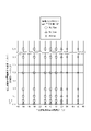
- Fig. 1 summarizes the above evaluation results in terms of the relationship between the atmospheric dew point and atmospheric gas flow rate during final annealing and the film adhesion. From the results shown in FIG. 1, it can be seen that good film adhesion can be obtained by setting the flow rate of the atmosphere gas to 0.2 L/min or more per ton of steel material and the dew point to 10° C. or less in the finish annealing atmosphere.
- the portion of the coil that showed the representative value that is, the portion with the poorest film adhesion was mostly the central portion in the longitudinal direction and the width direction of the coil.
- a steel slab for grain-oriented electrical steel sheets containing 0.075% C, 2.88% Si, 0.05% Mn, 0.015% Se, 0.08% Sb, 0.021% Al, and 0.008% N, in mass%, is 1380
- a hot-rolled sheet with a thickness of 2.4 mm is produced by hot rolling, and this hot-rolled sheet is subjected to hot-rolled sheet annealing at 900°C for 30 seconds, and the scale on the surface of the steel sheet is pickled. After removing it, it was cold rolled to a thickness of 1.6 mm. Then, after performing intermediate annealing at 1125° C.
- the second cold rolling was performed to finish the plate to a thickness of 0.23 mm.
- decarburization annealing was performed at 850°C x 90 seconds, 50% H 2 +50% N 2 , dew point 64°C.
- final annealing was performed at 1200° C. for 20 hours. After the annealing separator was applied and dried, only the annealing separator on the steel sheet was sampled, and the ignition loss was measured by the method described in JIS K0067:1992 and found to be 1.4% by mass.
- the atmosphere of the final annealing was N2 atmosphere during heating up to 850°C, H2 atmosphere from 850°C to 1200°C, and Ar atmosphere during subsequent cooling. At this time, the atmospheric dew point was ⁇ 50° C., and the atmospheric gas flow rate was 1.0 L/min per ton of steel material.
- pickling treatment is performed for various times with hydrochloric acid having various concentrations and temperatures.
- flattening annealing which combines coating baking (coating treatment) at 870° C. for 20 seconds and flattening of the steel sheet, was performed.
- the film adhesion of the obtained steel plate was evaluated.
- Coating adhesion was evaluated by winding steel sheets around cylinders having various diameters and determining the minimum diameter at which the coating did not peel off.
- the points where samples were taken for evaluation were two points at both ends in the longitudinal direction of the coil and one point at the center of the same at each end and at each central part of the same in the longitudinal direction of the coil. Samples with a size of 280 mm in the rolling direction and 30 mm in the width direction were taken from different locations, and the minimum diameter at which the film did not peel off was measured.
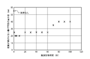
- Figs. 2 to 4 show the relationship between the acid concentration, acid temperature, pickling treatment time and film adhesion in the pickling treatment before applying the coating liquid.
- An experiment was also conducted under the condition that the pickling treatment was not performed before the application of the coating liquid, and the evaluation result of the film adhesion is shown in FIG. 4 as pickling treatment time dependence of pickling treatment time of 0 seconds. From the results shown in FIGS. 2 to 4, in the flattening annealing, an acid having a concentration of 1.0% by mass or more and 20.0% by mass or less was used at a temperature of 15° C. or more for 1 second or more and 60 seconds or less before applying the coating liquid. It can be seen that good film adhesion is exhibited by washing treatment.
- the portion that exhibited the representative value of the coil that is, the portion with the poorest film adhesion was mostly the central portion in each of the longitudinal and width directions of the coil.
- the deterioration of coating adhesion is presumed to be due to the concentration of S and Se in the vicinity of the base iron coating interface.
- the S and Se exist in the steel by forming precipitates such as MnS and MnSe before final annealing. During long-term final annealing, these precipitates are decomposed, and S and Se are liberated and diffused to the surface, reacting with H on the surface and released into the gas phase as H 2 S and H 2 Se. , part of which remains in the vicinity of the base metal film interface, and induces the deterioration of film adhesion as described above.
- MgO which is used as an annealing separator, to improve the circulation of atmosphere gas between the steel sheets.
- the annealing separator is suspended in water and applied in the form of a slurry, but the surface layer of the MgO particles is hydrated by the water to form Mg(OH) 2 . For this reason, it shows some volume expansion, but it is thought that by keeping the atmospheric dew point in the final annealing below a certain level, the moisture is released and the volume shrinks, and the flowability of the atmospheric gas is improved.
- MgO is hydrated and expanded to some extent before the final annealing because it is expected that the volume shrinks during the final annealing and the gas flowability improves. It is presumed that there is an effect if there is a hydration amount of 1% by mass or more.
- the fact that MgO has a hydration amount of 1% by mass or more means that the ignition loss after drying (in accordance with JIS K0067: 1992) is 1% by mass or more in the annealing separator containing MgO as the main component. means that
- the present inventors determined the conditions of the pickling treatment before the application of the coating liquid and the conditions of the atmosphere introduced in the final annealing to stably obtain good coating properties. I came to know what I could get. The present invention is based on the above findings.
- the gist and configuration of the present invention are as follows. 1. % by mass, Si: 2.0% or more and 5.0% or less, Mn: 0.01% or more and 0.50% or less, and either one of S and Se or a total of 0.001% and 0.100% or less of both S and Se After rolling, the steel is cold-rolled once or cold-rolled twice or more with intermediate annealing, then decarburized and annealed.
- finish annealing is performed in an atmosphere in which the atmosphere gas has a flow rate of 0.2 L/min or more per ton of steel sheet and a dew point of 10°C or less
- the planarization annealing is accompanied by a coating process including application of a coating liquid
- pickling treatment is performed using an acid having a concentration of 1.0% by mass or more and 20.0% by mass or less at a temperature of 15° C. or more for 1 second or more and 60 seconds or less.
- FIG. 3 is a diagram showing the relationship between the atmosphere dew point and the flow rate of the atmosphere gas during final annealing and the film adhesion.
- FIG. 5 is a diagram showing the relationship between acid concentration and film adhesion in pickling treatment before application of a coating liquid.
- FIG. 5 is a diagram showing the relationship between acid temperature and film adhesion in pickling treatment before application of a coating liquid.
- FIG. 5 is a diagram showing the relationship between the pickling treatment time and film adhesion in the pickling treatment before applying the coating liquid.
- Si 2.0% to 5.0% Si is an element necessary to increase the resistivity of steel and improve iron loss. The content is made 2.0% or more and 5.0% or less because the steel properties deteriorate and rolling becomes difficult. Si is desirably 3.0% or more. Si is desirably 3.6% or less.
- Mn 0.01% or more and 0.50% or less Mn is an element necessary for good hot workability, but if it is less than 0.01%, the effect is poor. Therefore, the content should be 0.01% or more and 0.50% or less. Mn is desirably 0.03% or more. Mn is desirably 0.15% or less.
- Any one or two of S and Se 0.001% or more and 0.100% or less in total
- the problem solved by the present invention is considered to be mainly caused by S and Se in steel. , is premised on containing these elements. That is, if the sum of any one or two of S and Se is less than 0.001%, the problem itself does not occur, whereas if it exceeds 0.100%, secondary recrystallization becomes difficult, so 0.001 % or more and 0.100% or less.
- the above sum is desirably 0.003% or more.
- the above sum is desirably 0.030% or less.
- C can be contained by 0.01% or more and 0.10% or less.
- C is desirably 0.03% or more and 0.08% or less.
- AlN 0.01% or more and 0.04% or less and N: 0.003% or more and 0.010% or less can be included.
- Ni 0% to 1.50%
- Cr 0% to 0.50%
- Cu 0% to 0.50%
- P 0% to 0.50%
- Sb 0% more than 0.50%
- Sn more than 0% and less than 0.50%
- Bi more than 0% and less than 0.50%
- Mo more than 0% and less than 0.50%
- B more than 0 ppm and less than 25 ppm
- Nb more than 0% and less than 0.020%
- V More than 0% and 0.010% or less
- Zr more than 0% and 0.10% or less
- Co more than 0% and 0.050% or less
- Pb more than 0% and 0.0100% or less
- One of W: more than 0% and 0.0100% or less, Ge: more than 0% and 0.0050% or less, and Ga: more than 0% and 0.0050% or less can be added sing
- the steel material having the above-described components may be produced as a slab by a normal ingot casting method or continuous casting method, or may be produced as a thin slab having a thickness of 100 mm or less by a direct casting method. These slabs and thin cast pieces as steel materials are usually hot rolled after being reheated, but may be hot rolled immediately after casting without heating.
- Hot rolling especially hot rolling after reheating, includes one pass or more of rough rolling at 900°C or higher and 1200°C or lower, followed by two or more passes of finish rolling at 700°C or higher and 1000°C or lower. is desirable from the viewpoint of structure control of the hot-rolled sheet. Moreover, after hot rolling, it can be wound into a coil. In that case, it is desirable to set the coiling temperature to 400° C. or higher and 750° C. or lower from the viewpoint of both carbide morphology control and defect prevention such as cracking.
- the winding temperature is more desirably 500°C or higher and 700°C or lower.
- hot-rolled sheet annealing After hot rolling, hot-rolled sheet annealing can be applied as needed.
- the structure When the hot-rolled sheet is annealed, the structure can be homogenized, and variations in magnetic properties can be reduced.
- the temperature condition for hot-rolled sheet annealing is desirably 800° C. or higher and 1250° C. or lower, and the holding time for hot-rolled sheet annealing is desirably 5 seconds or longer. More preferably, the temperature condition for hot-rolled sheet annealing is 900° C. or more and 1150° C. or less, and the holding time for hot-rolled sheet annealing is 10 seconds or more and 180 seconds or less. After the hot-rolled sheet is annealed, it can be cooled.
- Such cooling is preferably performed at a cooling rate of 5°C/s or more and 100°C/s or less in the temperature range from 800°C to 350°C from the viewpoint of controlling the morphology of the second phase and precipitates. More desirably, the cooling rate is 15° C./s or higher and 45° C./s or lower.
- the steel sheet is subjected to one cold rolling or two or more cold rollings with intermediate annealing between them to obtain a final thickness, and then subjected to decarburization annealing.
- intermediate annealing it is desirable from the viewpoint of structure control to hold the steel in the temperature range of 800° C. or higher and 1250° C. or lower for 5 seconds or longer.
- the cooling rate from 800° C. to 350° C.
- the cooling rate is 15° C./s or higher and 45° C./s or lower.
- a lubricant such as rolling oil in order to reduce the rolling load and improve the rolling shape. Further, it is desirable to set the total rolling reduction in the final cold rolling to 50% or more and 92% or less in order to obtain a good recrystallized texture before secondary recrystallization.
- the cold-rolled steel sheet after the final cold rolling is subjected to decarburization annealing, but before that, it is desirable to clean the steel sheet surface by degreasing and pickling.
- Decarburization annealing is carried out in a temperature range of 750°C or higher and 950°C or lower for 10 seconds or more, the atmospheric gas contains H2 and N2 , and the dew point is 20°C or higher in part or all of the decarburization annealing.
- a moist atmosphere of 80°C or less is desirable. More desirable conditions for the atmosphere are conditions in which the temperature range is 800° C. or higher and 900° C. or lower and the dew point is 30° C. or higher and 70° C. or lower.
- an annealing separator mainly composed of MgO is applied to the steel sheet and dried.
- the amount of the annealing separating agent applied to the surface of the steel sheet is desirably 2.5 g/m 2 or more per side.
- "mainly composed of MgO” means that the content of MgO in the annealing separator is 60% by mass or more in terms of solid content.
- the content of MgO in the annealing separator is preferably 80% by mass or more in terms of solid content.
- MgO is applied to the steel plate as a slurry solution suspended in water.At that time, the slurry solution is maintained at a constant temperature within the range of 5°C to 30°C in order to suppress the increase in viscosity. It is desirable that
- the annealing separator preferably has an ignition loss after drying of 1.0% by mass or more and 7.0% by mass or less. The ignition loss is measured according to JIS K0067:1992.
- the annealing separator it is desirable to separate the slurry solution of the annealing separator into a mixing tank and a coating tank in order to keep the slurry concentration constant when coating.
- This annealing separating agent is made into a slurry solution, applied, dried, and then subjected to finish annealing, whereby secondary recrystallized grains can be developed and a forsterite coating can be formed.
- the temperature is desirably raised to 800°C or higher in order to complete the secondary recrystallization, and in the case of forming a forsterite film, the temperature is desirably raised to 1050°C or higher.
- finish annealing generally takes a long time, so the coil is charged in the finish annealing furnace in an up-end state and subjected to annealing. Therefore, it is desirable to wind a band or the like around the coil before finish annealing to prevent the outer winding of the up-end coil from unwinding.
- the temperature is maintained at a temperature of 1050 ° C. or higher and 1300 ° C. or lower for 3 hours or more, and the temperature is 1050 ° C. or higher. It is desirable to introduce an atmosphere containing H 2 partly or entirely within the temperature range of .
- the atmosphere gas flow rate per ton of steel it is important to set the atmosphere gas flow rate per ton of steel to 0.2 L/min or more and the atmosphere dew point to 10°C or less.
- the atmospheric dew point is preferably 0° C. or lower.
- the flow rate of atmospheric gas per ton of steel material is preferably 0.5 L/min or more.
- the flattening annealing is accompanied by a coating process including application of a coating liquid.
- an acid with a concentration of 1.0% or more and 20.0% or less is used for pickling at a temperature of 15° C. or more for 1 second or more and 60 seconds or less.
- concentration of the acid is preferably 2.0% or more and 10.0% or less.
- the temperature of the acid is preferably 40°C or higher and preferably 90°C or lower.
- the time for the pickling treatment is preferably 2 seconds or more and 15 seconds or less.
- the acid used for the pickling treatment is desirably phosphoric acid, hydrochloric acid, sulfuric acid, or nitric acid.
- the insulating coating is preferably a coating that can apply tension to the steel sheet to reduce iron loss.
- Example 1 A steel slab for grain-oriented electrical steel sheets containing Si: 2.99%, Mn: 0.09%, and Se: 0.014% by mass is reheated to a temperature of 1400°C and hot-rolled into a 2.7mm thick hot-rolled sheet. After the scale on the surface of the steel sheet was removed by pickling, the steel sheet was cold-rolled to a thickness of 0.68 mm. Then, it was subjected to intermediate annealing at 900° C. for 100 seconds, and then to cold rolling for the second time, finishing to a plate thickness of 0.23 mm. After that, decarburization annealing was performed at 850°C for 120 seconds, 50% H 2 +50% N 2 , dew point 62°C.
- the surface of the steel sheet was coated with an annealing separator mainly composed of MgO, dried, and then finished annealed at 1210° C. for 10 hours.
- an annealing separator mainly composed of MgO, dried, and then finished annealed at 1210° C. for 10 hours.
- the annealing separator only the annealing separator on the steel sheet was sampled, and the ignition loss was measured by the method described in JIS K0067:1992, which was 2.5%.
- the atmosphere of the final annealing is an N2 atmosphere during the temperature rise up to 1000°C, an H2 atmosphere from 1100°C to 1210°C, and an Ar atmosphere during cooling until the temperature reaches 1000°C. did.
- the atmosphere dew point and the atmosphere gas flow rate were changed as shown in Table 1.
- pickling treatment is performed with phosphoric acid at the acid concentration and acid temperature shown in Table 1 for the time shown in Table 1, and then, A coating solution mainly composed of phosphate was applied, and flattening annealing was performed at 820°C for 100 seconds to bake the coating (coating treatment) and to flatten the steel plate.
- Coating adhesion was evaluated by winding steel sheets around cylinders having various diameters and determining the minimum diameter at which the coating did not peel off. In addition, the evaluation was carried out at two locations in the width direction of the coil and one location in the center of the coil at each end portion and center portion of both sides in the longitudinal direction of the coil, that is, a total of nine locations in one coil to a length of 280 mm in the rolling direction. , and 30 mm in the width direction, the minimum diameter at which the film does not peel off was measured, and the maximum value at the nine locations was taken as the representative value for each coil.
- Example 2 A steel slab for grain-oriented electrical steel sheets containing C: 0.075%, Si: 3.66%, Mn: 0.24%, and S: 0.028% by mass was reheated to a temperature of 1420°C and hot rolled to a thickness of 2.2 mm.
- a hot-rolled sheet was produced, subjected to hot-rolled sheet annealing at 980° C. for 30 seconds, and after removing scales from the surface of the steel sheet by pickling, it was cold-rolled to a thickness of 1.20 mm. Then, it was subjected to intermediate annealing at 1100° C. for 100 seconds, and then to cold rolling for the second time to finish the plate to a thickness of 0.23 mm.
- decarburization annealing was performed at 850°C for 120 seconds, 48% H 2 +52% N 2 , dew point 63°C. Thereafter, the surface of the steel sheet was coated with an annealing separator mainly composed of MgO, dried, and then finished annealed at 1200° C. for 10 hours.
- the temperature of the coating solution for the annealing separator was adjusted to 10° C., and the hydration amount of MgO was changed as shown in Table 2 by changing the mixing time.
- the annealing separator only the annealing separator on the steel sheet was sampled, and the ignition loss was measured by the method described in JIS K0067:1992, and the hydration amount was taken as the value.
- the atmosphere of the final annealing is an N2 atmosphere during the temperature rise up to 900°C, an H2 atmosphere from 900°C to 1200°C, and an Ar atmosphere during the subsequent cooling until the temperature reaches 900°C. did.
- the atmospheric dew point was set at ⁇ 55° C.
- the atmosphere gas was introduced at a flow rate of 1.5 L/min per ton of steel material.
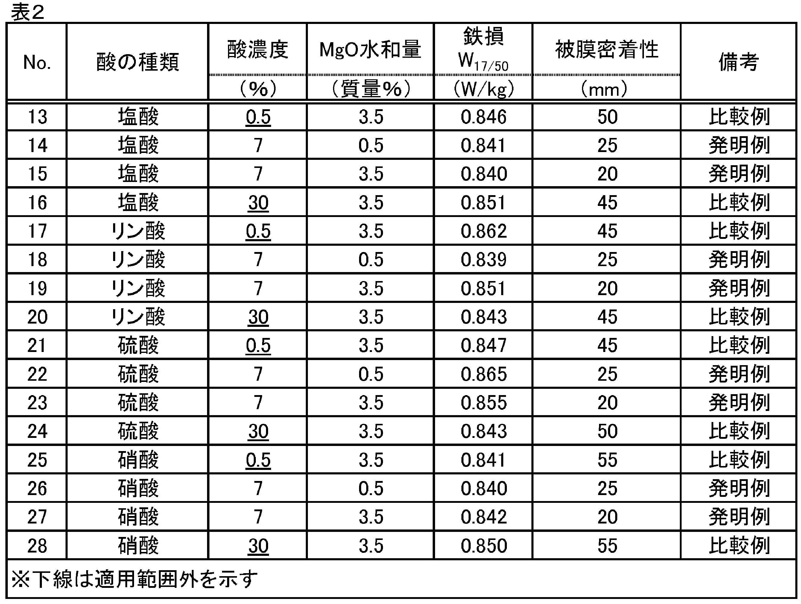
- pickling treatment was carried out at 60° C. for 5 seconds using the kind of acid and acid concentration shown in Table 2. After that, a coating solution mainly containing phosphate was applied, and flattening annealing was performed at 860° C. for 35 seconds to bake the coating (coating treatment) and flatten the steel sheet.
- Coating adhesion was evaluated by winding steel sheets around cylinders having various diameters and determining the minimum diameter at which the coating did not peel off. In addition, the evaluation was carried out at two locations in the width direction of the coil and one location in the center of the coil at each end portion and center portion of both sides in the longitudinal direction of the coil, that is, a total of nine locations in one coil to a length of 280 mm in the rolling direction. , and 30 mm in the width direction, the minimum diameter at which the film does not peel off was measured, and the maximum value at the nine locations was taken as the representative value for each coil.
Landscapes
- Chemical & Material Sciences (AREA)
- Engineering & Computer Science (AREA)
- Physics & Mathematics (AREA)
- Materials Engineering (AREA)
- Mechanical Engineering (AREA)
- Metallurgy (AREA)
- Organic Chemistry (AREA)
- Thermal Sciences (AREA)
- Crystallography & Structural Chemistry (AREA)
- Electromagnetism (AREA)
- Manufacturing & Machinery (AREA)
- General Chemical & Material Sciences (AREA)
- Chemical Kinetics & Catalysis (AREA)
- Dispersion Chemistry (AREA)
- Power Engineering (AREA)
- Manufacturing Of Steel Electrode Plates (AREA)
- Chemical Treatment Of Metals (AREA)
- Soft Magnetic Materials (AREA)
Abstract
Description
<実験1>
質量%で、C:0.025%、Si:3.14%、Mn:0.15%、Se:0.021%を含む方向性電磁鋼板用鋼スラブを、1400℃の温度に再加熱し、熱間圧延により2.7mm厚の熱延板を作製し、次いで1000℃で15秒の熱延板焼鈍を施し、鋼板表面のスケールを酸洗にて除去した後に、冷間圧延を施して0.55mmの板厚とした。次いで、1080℃で100秒の中間焼鈍を施した後に2回目の冷間圧延を施し、板厚0.23mmに仕上げた。その後、850℃×90秒、50%H2+50%N2、露点62℃で脱炭焼鈍を施した。次いで、鋼板表面にMgO主体の焼鈍分離剤を塗布して乾燥した後、1200℃で15時間の仕上焼鈍を施した。この焼鈍分離剤の塗布および乾燥の後に、鋼板上の焼鈍分離剤だけを採取し、JIS K0067:1992記載の方法で強熱減量を測定したところ、3.2質量%であった。
質量%で、C:0.075%、Si:2.88%、Mn:0.05%、Se:0.015%、Sb:0.08%、Al:0.021%、N:0.008%を含む方向性電磁鋼板用鋼スラブを、1380℃の温度に再加熱し、熱間圧延により2.4mm厚の熱延板を作製し、この熱延板に900℃で30秒の熱延板焼鈍を施し、鋼板表面のスケールを酸洗にて除去した後に、冷間圧延を施して1.6mmの板厚とした。次いで、1125℃で120秒の中間焼鈍を施した後に2回目の冷間圧延を施し、板厚0.23mmに仕上げた。その後、850℃×90秒、50%H2+50%N2、露点64℃の脱炭焼鈍を施した。次いで、鋼板表面にMgO主体の焼鈍分離剤を塗布して乾燥した後、1200℃で20時間の仕上焼鈍を施した。この焼鈍分離剤の塗布および乾燥の後に、鋼板上の焼鈍分離剤だけを採取し、JIS K0067:1992記載の方法で強熱減量を測定したところ、1.4質量%であった。
1.質量%で、Si:2.0%以上5.0%以下、Mn:0.01%以上0.50%以下、SおよびSeのうちいずれか1種または2種合計で0.001%以上0.100%以下を含む鋼素材に、熱間圧延を施した後、1回の冷間圧延または中間焼鈍を挟む2回以上の冷間圧延を施し、次いで脱炭焼鈍を施し、さらにMgOを主体とする焼鈍分離剤を塗布して乾燥した後、仕上焼鈍を施し、次いで平坦化焼鈍を施す、工程を含む、方向性電磁鋼板の製造方法であって、
前記仕上焼鈍は、雰囲気ガスの流量が鋼板1トン当たり0.2L/min以上および露点が10℃以下である雰囲気にて施し、
前記平坦化焼鈍は、コーティング液の塗布を含むコーティング処理を伴い、
前記コーティング液の塗布前に、濃度1.0質量%以上20.0質量%以下の酸を用いて、温度15℃以上で1秒以上60秒以下の酸洗処理を行う、方向性電磁鋼板の製造方法。
<鋼素材>
まず初めに、方向性電磁鋼板の鋼素材(鋼スラブ)の成分組成について、以下に望ましい成分組成の範囲を記載する。なお、成分に関する「%」表示は、特に断らない限り「質量%」を意味するものとする。
Siは、鋼の比抵抗を高め、鉄損を改善させるために必要な元素であるが、2.0%未満であると効果が乏しく、5.0%を超えると鋼の加工性が劣化し、圧延が困難となることから2.0%以上5.0%以下とする。Siは、望ましくは、3.0%以上である。Siは、望ましくは、3.6%以下である。
Mnは、熱間加工性を良好にするために必要な元素であるが、0.01%未満であると効果が乏しく、0.50%を超えると製品板の磁束密度が低下するため、0.01%以上0.50%以下とする。Mnは、望ましくは0.03%以上である。Mnは、望ましくは、0.15%以下である。
本発明で解決された課題は、鋼中のSやSeが主因であると考えられることから、本発明においては、これら元素を含むことが前提となる。すなわち、SおよびSeのうちいずれか1種または2種の合計は、0.001%未満では課題自体が発生することがなく、一方0.100%超であれば、二次再結晶が困難となるため、0.001%以上0.100%以下に限定する。上記合計は、望ましくは、0.003%以上である。上記合計は、望ましくは、0.030%以下である。
すなわち、鋳込み時や熱間圧延時の端部割れや表面欠陥を抑制するために、Cを0.01%以上0.10%以下含有させることができる。Cは、望ましくは、0.03%以上であり、また、0.08%以下である。
上記成分を有する鋼素材は、通常の造塊法、連続鋳造法でスラブとして製造してもよいし、直接鋳造法で100mm以下の厚さの薄鋳片として製造してもよい。これら鋼素材としてのスラブや薄鋳片は、通常は再加熱された後に熱間圧延を施すが、鋳造後加熱せずに直ちに熱間圧延を施してもよい。
質量%で、Si:2.99%、Mn:0.09%、Se:0.014%を含む方向性電磁鋼板用鋼スラブを、1400℃の温度に再加熱し、熱間圧延により2.7mm厚の熱延板を作製し、鋼板表面のスケールを酸洗にて除去した後に冷間圧延を施して、0.68mmの板厚とした。次いで、900℃で100秒の中間焼鈍を施し、その後2回目の冷間圧延を施し、板厚0.23mmに仕上げた。その後、850℃×120秒、50%H2+50%N2、露点62℃の脱炭焼鈍を施した。その後、鋼板表面にMgO主体の焼鈍分離剤を塗布して乾燥した後、1210℃で10時間の仕上焼鈍を施した。焼鈍分離剤の塗布および乾燥後に、鋼板上の焼鈍分離剤だけを採取し、JIS K0067:1992記載の方法で強熱減量を測定したところ、2.5%であった。

質量%で、C:0.075%、Si:3.66%、Mn:0.24%、S:0.028%を含む方向性電磁鋼板用鋼スラブを、1420℃の温度に再加熱し、熱間圧延により2.2mm厚の熱延板を作製し、980℃で30秒の熱延板焼鈍を施し、鋼板表面のスケールを酸洗にて除去した後に冷間圧延を施して、1.20mmの板厚とした。次いで、1100℃で100秒の中間焼鈍を施し、その後2回目の冷間圧延を施し、板厚0.23mmに仕上げた。その後、850℃×120秒、48%H2+52%N2、露点63℃の脱炭焼鈍を施した。その後、鋼板表面にMgO主体の焼鈍分離剤を塗布して乾燥した後、1200℃で10時間の仕上焼鈍を施した。焼鈍分離剤の塗布液を調合したときの液温を10℃とし、調合時間を変更してMgOの水和量を表2に記載のごとく変化させた。水和量は、焼鈍分離剤の塗布および乾燥後に、鋼板上の焼鈍分離剤だけを採取し、JIS K0067:1992記載の方法で強熱減量を測定し、その値とした。
Claims (3)
- 質量%で、Si:2.0%以上5.0%以下、Mn:0.01%以上0.50%以下、SおよびSeのうちいずれか1種または2種合計で0.001%以上0.100%以下を含む鋼素材に、熱間圧延を施した後、1回の冷間圧延または中間焼鈍を挟む2回以上の冷間圧延を施し、次いで脱炭焼鈍を施し、さらにMgOを主体とする焼鈍分離剤を塗布して乾燥した後、仕上焼鈍を施し、次いで平坦化焼鈍を施す、工程を含む、方向性電磁鋼板の製造方法であって、
前記仕上焼鈍は、雰囲気ガスの流量が鋼板1トン当たり0.2L/min以上および露点が10℃以下である雰囲気にて施し、
前記平坦化焼鈍は、コーティング液の塗布を含むコーティング処理を伴い、
前記コーティング液の塗布前に、濃度1.0質量%以上20.0質量%以下の酸を用いて、温度15℃以上で1秒以上60秒以下の酸洗処理を行う、方向性電磁鋼板の製造方法。 - 前記酸は、リン酸、塩酸、硫酸、または硝酸のいずれかである、請求項1に記載の方向性電磁鋼板の製造方法。
- 前記焼鈍分離剤は、乾燥後の強熱減量が1.0質量%以上7.0質量%以下である、請求項1または2に記載の方向性電磁鋼板の製造方法。
Priority Applications (5)
| Application Number | Priority Date | Filing Date | Title |
|---|---|---|---|
| EP22811428.6A EP4335937A4 (en) | 2021-05-28 | 2022-05-27 | METHOD FOR PRODUCING A GRAIN-ORIENTED ELECTRICAL STEEL SHEET |
| CN202280036673.5A CN117460850A (zh) | 2021-05-28 | 2022-05-27 | 取向性电磁钢板的制造方法 |
| KR1020237039061A KR20230170744A (ko) | 2021-05-28 | 2022-05-27 | 방향성 전기 강판의 제조 방법 |
| US18/561,064 US20240254601A1 (en) | 2021-05-28 | 2022-05-27 | Method for producing grain-oriented electrical steel sheet |
| JP2022571888A JP7509240B2 (ja) | 2021-05-28 | 2022-05-27 | 方向性電磁鋼板の製造方法 |
Applications Claiming Priority (2)
| Application Number | Priority Date | Filing Date | Title |
|---|---|---|---|
| JP2021-090690 | 2021-05-28 | ||
| JP2021090690 | 2021-05-28 |
Publications (1)
| Publication Number | Publication Date |
|---|---|
| WO2022250160A1 true WO2022250160A1 (ja) | 2022-12-01 |
Family
ID=84228962
Family Applications (1)
| Application Number | Title | Priority Date | Filing Date |
|---|---|---|---|
| PCT/JP2022/021833 Ceased WO2022250160A1 (ja) | 2021-05-28 | 2022-05-27 | 方向性電磁鋼板の製造方法 |
Country Status (6)
| Country | Link |
|---|---|
| US (1) | US20240254601A1 (ja) |
| EP (1) | EP4335937A4 (ja) |
| JP (1) | JP7509240B2 (ja) |
| KR (1) | KR20230170744A (ja) |
| CN (1) | CN117460850A (ja) |
| WO (1) | WO2022250160A1 (ja) |
Citations (8)
| Publication number | Priority date | Publication date | Assignee | Title |
|---|---|---|---|---|
| JPS4015644B1 (ja) | 1963-04-05 | 1965-07-21 | ||
| JPS5113469B2 (ja) | 1972-10-13 | 1976-04-28 | ||
| JPH0230778A (ja) | 1988-07-21 | 1990-02-01 | Kawasaki Steel Corp | 電磁特性とコーディング密着性の優れた一方向性珪素鋼板の製造方法 |
| JPH02125815A (ja) * | 1988-07-20 | 1990-05-14 | Kawasaki Steel Corp | 磁気特性の優れた一方向性珪素鋼板の製造方法 |
| JPH09111346A (ja) * | 1995-10-17 | 1997-04-28 | Nippon Steel Corp | 超低鉄損超高磁束密度一方向性電磁鋼帯の製造方法 |
| JPH10158744A (ja) * | 1996-12-03 | 1998-06-16 | Nippon Steel Corp | 表面性状および磁気特性の優れた方向性電磁鋼板の製造方法 |
| JP2000129356A (ja) | 1998-10-28 | 2000-05-09 | Kawasaki Steel Corp | 方向性電磁鋼板の製造方法 |
| US20160108488A1 (en) * | 2014-10-15 | 2016-04-21 | Sms Siemag Ag | Process for producing grain-oriented electrical steel strip and grain-oriented electrical steel strip obtained according to said process |
Family Cites Families (6)
| Publication number | Priority date | Publication date | Assignee | Title |
|---|---|---|---|---|
| JPS6049852A (ja) * | 1983-08-30 | 1985-03-19 | Ube Ind Ltd | 金型用ガス抜き装置の制御方法 |
| EP0525467B1 (en) * | 1991-07-10 | 1997-03-26 | Nippon Steel Corporation | Grain oriented silicon steel sheet having excellent primary glass film properties |
| JPH0762439A (ja) * | 1993-08-25 | 1995-03-07 | Nippon Steel Corp | 方向性電磁鋼板の品質制御方法 |
| JP4015644B2 (ja) | 2004-05-31 | 2007-11-28 | 株式会社ソニー・コンピュータエンタテインメント | 画像処理装置及び画像処理方法 |
| JP6512412B2 (ja) * | 2016-01-29 | 2019-05-15 | Jfeスチール株式会社 | 方向性電磁鋼板およびその製造方法 |
| CN109112283A (zh) * | 2018-08-24 | 2019-01-01 | 武汉钢铁有限公司 | 低温高磁感取向硅钢的制备方法 |
-
2022
- 2022-05-27 EP EP22811428.6A patent/EP4335937A4/en active Pending
- 2022-05-27 KR KR1020237039061A patent/KR20230170744A/ko active Pending
- 2022-05-27 US US18/561,064 patent/US20240254601A1/en active Pending
- 2022-05-27 WO PCT/JP2022/021833 patent/WO2022250160A1/ja not_active Ceased
- 2022-05-27 CN CN202280036673.5A patent/CN117460850A/zh active Pending
- 2022-05-27 JP JP2022571888A patent/JP7509240B2/ja active Active
Patent Citations (8)
| Publication number | Priority date | Publication date | Assignee | Title |
|---|---|---|---|---|
| JPS4015644B1 (ja) | 1963-04-05 | 1965-07-21 | ||
| JPS5113469B2 (ja) | 1972-10-13 | 1976-04-28 | ||
| JPH02125815A (ja) * | 1988-07-20 | 1990-05-14 | Kawasaki Steel Corp | 磁気特性の優れた一方向性珪素鋼板の製造方法 |
| JPH0230778A (ja) | 1988-07-21 | 1990-02-01 | Kawasaki Steel Corp | 電磁特性とコーディング密着性の優れた一方向性珪素鋼板の製造方法 |
| JPH09111346A (ja) * | 1995-10-17 | 1997-04-28 | Nippon Steel Corp | 超低鉄損超高磁束密度一方向性電磁鋼帯の製造方法 |
| JPH10158744A (ja) * | 1996-12-03 | 1998-06-16 | Nippon Steel Corp | 表面性状および磁気特性の優れた方向性電磁鋼板の製造方法 |
| JP2000129356A (ja) | 1998-10-28 | 2000-05-09 | Kawasaki Steel Corp | 方向性電磁鋼板の製造方法 |
| US20160108488A1 (en) * | 2014-10-15 | 2016-04-21 | Sms Siemag Ag | Process for producing grain-oriented electrical steel strip and grain-oriented electrical steel strip obtained according to said process |
Also Published As
| Publication number | Publication date |
|---|---|
| JPWO2022250160A1 (ja) | 2022-12-01 |
| CN117460850A (zh) | 2024-01-26 |
| EP4335937A1 (en) | 2024-03-13 |
| EP4335937A4 (en) | 2024-10-30 |
| KR20230170744A (ko) | 2023-12-19 |
| US20240254601A1 (en) | 2024-08-01 |
| JP7509240B2 (ja) | 2024-07-02 |
Similar Documents
| Publication | Publication Date | Title |
|---|---|---|
| CN107849656A (zh) | 取向性电磁钢板及其制造方法 | |
| CN115066508B (zh) | 方向性电磁钢板的制造方法 | |
| CN102197149A (zh) | 方向性电磁钢板的制造方法 | |
| WO2011102456A1 (ja) | 方向性電磁鋼板の製造方法 | |
| JP4962516B2 (ja) | 方向性電磁鋼板の製造方法 | |
| JP7517472B2 (ja) | 方向性電磁鋼板の製造方法 | |
| WO2020149321A1 (ja) | 方向性電磁鋼板の製造方法 | |
| CN118696135A (zh) | 取向性电磁钢板的制造方法 | |
| JP2009228117A (ja) | 方向性電磁鋼板の製造方法 | |
| JP7226678B1 (ja) | 方向性電磁鋼板の製造方法 | |
| JP4784347B2 (ja) | 方向性電磁鋼板の製造方法 | |
| JP2008106367A (ja) | 二方向性電磁鋼板 | |
| JP7214974B2 (ja) | 方向性電磁鋼板の製造方法 | |
| JP7761565B2 (ja) | 方向性電磁鋼板の製造方法 | |
| JP7509240B2 (ja) | 方向性電磁鋼板の製造方法 | |
| JP7226677B1 (ja) | 方向性電磁鋼板の製造方法 | |
| KR20230159875A (ko) | 방향성 전자 강판의 제조 방법 | |
| JP7255761B1 (ja) | 方向性電磁鋼板の製造方法 | |
| JP7264322B1 (ja) | 方向性電磁鋼板の製造方法 | |
| JP7800777B2 (ja) | 方向性電磁鋼板 | |
| RU2805838C1 (ru) | Способ производства листа анизотропной электротехнической стали | |
| JP7816664B1 (ja) | 方向性電磁鋼板の製造方法 | |
| JP7287584B2 (ja) | 方向性電磁鋼板の製造方法 | |
| JPH0797631A (ja) | 磁気特性および被膜特性に優れた高磁束密度方向性けい素鋼板の製造方法 | |
| WO2020149323A1 (ja) | 方向性電磁鋼板の製造方法 |
Legal Events
| Date | Code | Title | Description |
|---|---|---|---|
| ENP | Entry into the national phase |
Ref document number: 2022571888 Country of ref document: JP Kind code of ref document: A |
|
| 121 | Ep: the epo has been informed by wipo that ep was designated in this application |
Ref document number: 22811428 Country of ref document: EP Kind code of ref document: A1 |
|
| ENP | Entry into the national phase |
Ref document number: 20237039061 Country of ref document: KR Kind code of ref document: A |
|
| WWE | Wipo information: entry into national phase |
Ref document number: 1020237039061 Country of ref document: KR |
|
| WWE | Wipo information: entry into national phase |
Ref document number: 18561064 Country of ref document: US |
|
| WWE | Wipo information: entry into national phase |
Ref document number: 202317077900 Country of ref document: IN |
|
| WWE | Wipo information: entry into national phase |
Ref document number: 202280036673.5 Country of ref document: CN |
|
| WWE | Wipo information: entry into national phase |
Ref document number: 2022811428 Country of ref document: EP |
|
| ENP | Entry into the national phase |
Ref document number: 2022811428 Country of ref document: EP Effective date: 20231207 |
|
| NENP | Non-entry into the national phase |
Ref country code: DE |