WO2022254739A1 - ねじ締結具およびねじ締結具の機能付加部材 - Google Patents
ねじ締結具およびねじ締結具の機能付加部材 Download PDFInfo
- Publication number
- WO2022254739A1 WO2022254739A1 PCT/JP2021/034042 JP2021034042W WO2022254739A1 WO 2022254739 A1 WO2022254739 A1 WO 2022254739A1 JP 2021034042 W JP2021034042 W JP 2021034042W WO 2022254739 A1 WO2022254739 A1 WO 2022254739A1
- Authority
- WO
- WIPO (PCT)
- Prior art keywords
- portions
- sliding
- fastened
- insulating
- flange
- Prior art date
- Legal status (The legal status is an assumption and is not a legal conclusion. Google has not performed a legal analysis and makes no representation as to the accuracy of the status listed.)
- Ceased
Links
Images








Classifications
-
- F—MECHANICAL ENGINEERING; LIGHTING; HEATING; WEAPONS; BLASTING
- F16—ENGINEERING ELEMENTS AND UNITS; GENERAL MEASURES FOR PRODUCING AND MAINTAINING EFFECTIVE FUNCTIONING OF MACHINES OR INSTALLATIONS; THERMAL INSULATION IN GENERAL
- F16J—PISTONS; CYLINDERS; SEALINGS
- F16J15/00—Sealings
- F16J15/02—Sealings between relatively-stationary surfaces
- F16J15/021—Sealings between relatively-stationary surfaces with elastic packing
- F16J15/028—Sealings between relatively-stationary surfaces with elastic packing the packing being mechanically expanded against the sealing surface
-
- F—MECHANICAL ENGINEERING; LIGHTING; HEATING; WEAPONS; BLASTING
- F16—ENGINEERING ELEMENTS AND UNITS; GENERAL MEASURES FOR PRODUCING AND MAINTAINING EFFECTIVE FUNCTIONING OF MACHINES OR INSTALLATIONS; THERMAL INSULATION IN GENERAL
- F16B—DEVICES FOR FASTENING OR SECURING CONSTRUCTIONAL ELEMENTS OR MACHINE PARTS TOGETHER, e.g. NAILS, BOLTS, CIRCLIPS, CLAMPS, CLIPS OR WEDGES; JOINTS OR JOINTING
- F16B33/00—Features common to bolt and nut
- F16B33/004—Sealing; Insulation
-
- F—MECHANICAL ENGINEERING; LIGHTING; HEATING; WEAPONS; BLASTING
- F16—ENGINEERING ELEMENTS AND UNITS; GENERAL MEASURES FOR PRODUCING AND MAINTAINING EFFECTIVE FUNCTIONING OF MACHINES OR INSTALLATIONS; THERMAL INSULATION IN GENERAL
- F16B—DEVICES FOR FASTENING OR SECURING CONSTRUCTIONAL ELEMENTS OR MACHINE PARTS TOGETHER, e.g. NAILS, BOLTS, CIRCLIPS, CLAMPS, CLIPS OR WEDGES; JOINTS OR JOINTING
- F16B43/00—Washers or equivalent devices; Other devices for supporting bolt-heads or nuts
- F16B43/001—Washers or equivalent devices; Other devices for supporting bolt-heads or nuts for sealing or insulation
-
- F—MECHANICAL ENGINEERING; LIGHTING; HEATING; WEAPONS; BLASTING
- F16—ENGINEERING ELEMENTS AND UNITS; GENERAL MEASURES FOR PRODUCING AND MAINTAINING EFFECTIVE FUNCTIONING OF MACHINES OR INSTALLATIONS; THERMAL INSULATION IN GENERAL
- F16J—PISTONS; CYLINDERS; SEALINGS
- F16J15/00—Sealings
- F16J15/02—Sealings between relatively-stationary surfaces
- F16J15/06—Sealings between relatively-stationary surfaces with solid packing compressed between sealing surfaces
- F16J15/10—Sealings between relatively-stationary surfaces with solid packing compressed between sealing surfaces with non-metallic packing
- F16J15/12—Sealings between relatively-stationary surfaces with solid packing compressed between sealing surfaces with non-metallic packing with metal reinforcement or covering
- F16J15/128—Sealings between relatively-stationary surfaces with solid packing compressed between sealing surfaces with non-metallic packing with metal reinforcement or covering with metal covering
Definitions
- the present invention relates to screw fasteners such as bolts and nuts, and more particularly to screw fasteners provided with function-adding members that add sealing and insulating functions, and function-adding members used in screw fasteners.
- the bolt described in Patent Document 1 includes a bolt body having a threaded portion (shaft portion), a head portion formed at the upper end portion of the threaded portion, and a flange portion formed at the lower end portion of the head portion, It is composed of a non-conductive resin ring-shaped member (function adding member) that encloses the outer peripheral portion of the flange portion.
- the resin ring-shaped member has an edge portion located on the lower end side of the thread portion and outside the flange body portion relative to the seat surface, and an annular skirt portion that expands in diameter toward the edge portion.
- the resin ring-shaped member of the bolt described in Patent Document 1 and the nut described in Patent Document 2 increases the frictional force of the annular liquid-tight seal portion as it is tightened, and the flange portion of the bolt or nut rotates.
- the rotation of the annular liquid-tight seal portion is suppressed, and the resin ring-shaped member is largely twisted in the circumferential direction between the joint portion with the flange portion and the annular liquid-tight seal portion.
- there is a problem that the joint surface with the flange portion is peeled off, or the resin ring-shaped member is torn off due to a laceration.
- An object of the present invention is to provide a screw fastener with a function-added member that can prevent the function-added member from being damaged during tightening and that can maintain the good function and fastening state of the function-added member, and the function-added member of the screw fastener. is to provide
- the present invention A fastener body having a bearing surface, a screw portion for tightening the fastener body to a member to be fastened, a flange portion provided on the fastener body, and a function adding member provided on the flange portion,
- the function-adding member has at least a two-layer structure of a first additional portion having slidability provided on the flange portion and a second additional portion that contacts the member to be fastened. do.
- the interface between the contact portion between the first addition portion and the flange portion or the first addition portion and the second addition portion increases. It is possible to prevent the second addition portion from being excessively twisted due to the slipping of the interface of the contact portion of the additional portion, and there is no risk of damage to the second addition portion. Further, the contact portion between the first addition portion and the flange portion and the contact surface between the second addition portion and the first addition portion are sealed by the tightening force.
- the second additional portion is a sealing portion having a sealing function of sealing fluid by coming into close contact with the member to be fastened. In this way, the tightening force can be maintained without impairing the sealing function.
- the seal portion protrudes from the seating surface of the fastener body. When tightened, the sealing portion is compressed and deformed, and the bearing surface of the fastener body is seated on the member to be fastened, so that the axial force can be reliably secured.
- At least one of the first additional portion and the second additional portion is an insulator having an insulating function.
- the slidable first additional portion may be an insulator
- the second additional portion may be an insulator.
- the first addition portion may be configured to contact the flange portion so as to be rotatably slidable. By sliding the interface between the sliding portion and the metallic flange portion, damage to the sealing portion can be reliably prevented.
- the function-adding member may be detachably attached to the flange portion. By doing so, the function-adding member can be replaced.
- ⁇ Claim 7 Another invention is a function-adding member attached to a flange portion of a screw fastener,
- the function-adding member has at least a two-layer structure of a first addition portion having slidability that contacts the flange portion and a second addition portion that contacts the member to be fastened. do.
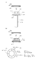
- FIG. 1 shows a screw fastener according to Embodiment 1 of the present invention
- FIG. 1(A) is a front view showing a cross section of a sealing function addition member
- FIG. 1(B) is a top view of the head side
- 1(C) is a partially enlarged cross-sectional view of the seal attachment portion of FIG. 1(A)
- FIG. 1(D) is an enlarged cross-sectional view of the seal portion and the anti-rotation portion of the sliding portion.
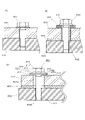
- FIGS. 2A and 2B illustrate the fastening structure of the bolt, where (A) is a schematic cross-sectional view of the overall structure and (B) is an enlarged cross-sectional view of the main part.
- FIG. 1 shows a screw fastener according to Embodiment 1 of the present invention
- FIG. 1(A) is a front view showing a cross section of a sealing function addition member
- FIG. 1(B) is a top view of the head side
- 1(C) is a
- FIG. 3 shows a screw fastener according to Embodiment 2 of the present invention
- FIG. 3(A) is a front view showing a cross section of the sealing function addition member
- FIG. 3(C) is a cross-sectional view of FIG. 3(A)
- FIG. 3(D) is an enlarged cross-sectional view of the main part of the mounting portion of the sealing function addition member of FIG. 3(A)
- FIG. 3(E) is a seal 2 is an enlarged cross-sectional view of the vicinity of the engaging portion of the part
- FIG. 4A is a cross-sectional view showing a usage example of the screw fastening portion of Embodiment 2
- FIG. 4B is a partially enlarged cross-sectional view of FIG. FIG.
- FIG. 5(A) is an explanatory view of assembling the sealing function adding member to the bolt
- FIG. 5(B) is an explanatory view of assembling the sealing function adding member to the nut
- FIG. 6 shows a screw fastener according to Embodiment 3 of the present invention
- FIG. 6(A) is a front view showing a cross section of an insulating function adding member
- FIG. 6(B) is a top view of the head side.
- 6(C) is a partially enlarged cross-sectional view of the seal attachment portion of FIG. 6(A)
- FIG. 6(D) is an enlarged cross-sectional view of the seal portion and the anti-rotation portion of the sliding portion.
- FIG. 7A and 7B show a reference example of a fastening structure of a jig for fixing a welding member of a resistance welding machine using bolts
- FIG. It is a structural example of the fastening structure using a bolt.
- 8A and 8B show a screw fastener according to Embodiment 4 of the present invention
- FIG. 8A is a front view showing a cross section of an insulating function addition member
- FIG. 8(C) is a cross-sectional view of FIG. 8(A)
- FIG. 8(D) is an enlarged cross-sectional view of the main part of the mounting portion of the insulating function addition member of FIG. 8(A)
- FIG. 10(A) is an explanatory diagram of when the insulating function-added member is attached to the bolt
- FIG. 10(B) is an explanatory diagram of when the insulating function-added member is attached to the nut
- FIG. 4D is a circumferential cross-sectional view of the contact surface taken along line DD of FIG. 4C.
- FIG. 11(A) is a vertical cross-sectional view of a bolt fastening state showing a modified example of Embodiment 1
- FIG. 11(B) is a bottom view of a nut
- FIG. Fig. 11(D) is a longitudinal sectional view showing another example of use of the bolt in Fig. 11(A).
- Fig. 12(A) is a vertical cross-sectional view of a tightened state of a nut showing a modified example of Embodiment 2
- Fig. 12(B) is a semi-longitudinal section showing an example of a stepped nut in which the flange portion of (A) is not provided with a bearing surface.
- FIG. 12(C) is a longitudinal sectional view of another example of use of the nut of (A).
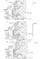
- 13A to 13C are partial cross-sectional views showing various modifications of the seal portion of the first and second embodiments.
- FIGS. 14A to 14D show various modifications of the annular protrusion and seat surface of the first and second embodiments.
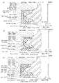
- 15A to 15C are partial cross-sectional views showing various modifications of the sealing function adding member of the first and second embodiments.
- FIGS. 16A and 16B are partial cross-sectional views showing modifications of the annular protrusions of Embodiments 3 and 4.
- FIG. 17A to 17C are partial cross-sectional views showing various modifications of the insulating function-adding member of Embodiments 3 and 4.
- FIG. 1 shows a screw fastener according to Embodiment 1 of the present invention.
- Embodiment 1 applies the present invention to a bolt, which is an example of an externally threaded member.
- FIGS. 1(A) and 1(B) the overall configuration will be described with reference to FIGS. 1(A) and 1(B).
- FIG. 1(A) is a front view showing a cross section of the sealing function adding member of the bolt, and FIG.
- the bolt 1 includes a head portion 10 as a fastener body having a bearing surface 17 and a shaft portion 13 formed with an external thread 13a for tightening the bearing surface 17 of the head portion 10 to a member 200 to be fastened. ing.
- a flange portion 14 is provided on the head portion 10, and an annular sealing function-adding member 20 as a function-adding member is attached to the flange portion 14, and the sealing function-adding member 20 is brought into close contact with the fastened member 200 during tightening. is configured to seal the fluid.
- the fluid to be sealed includes liquid such as water and gas such as air.
- the sealing function addition member 20 has at least a two-layer structure of a sliding portion 22 as a first addition portion that contacts the flange portion 14 and a seal portion 21 as a second addition portion that contacts the member 200 to be fastened. ing. Head 10 with flange 14 and shank 13 are made of metal.
- the head 10 has a hexagonal prism-shaped head body 11 for transmitting torque from the tightening tool, and a conical flange 14 projecting to a larger diameter than the diagonal distance of the head body 11.
- a side surface of the portion 14 on the shaft portion side is a flat bearing surface 17 that contacts the member to be fastened.
- the seat surface 17 is on a plane perpendicular to the central axis N of the shaft portion 13 or has an angle inclined toward the shaft portion 13 side. The inclination is inclined in a direction in which the root portion side is concave.
- the seat surface 17 may be an uneven surface.
- FIG. 1(C) is a partially enlarged cross-sectional view of the mounting portion of the sealing function adding member.
- the flange portion 14 includes a thick flange body 15 projecting in a truncated cone shape and an annular projecting portion 16 projecting outward from the outer circumference of the flange body 15 .
- the annular projecting portion 16 is thinner than the flange body 15 and protrudes from the middle portion of the outer circumference of the flange body 15 in the height direction.
- a side surface 16a on the head body side and a side surface 16b on the shaft portion side of the annular projecting portion 16 are surfaces orthogonal to the central axis N, and an outer peripheral surface 16c has an outwardly convex arcuate cross-sectional shape (a plane passing through the central axis N). cross section).
- a side surface of the flange main body 15 on the head main body 11 side is a first inclined surface 15a that is inclined in a direction of gradually increasing the diameter toward the shaft portion 13 side.
- a stepped wall 15c having a predetermined height is provided between the side surface 16a of the head portion 16 and the side surface 16a thereof.
- a corner portion 15b between the stepped wall 15c and the first inclined surface 15a has a convex rounded shape
- a corner portion between the stepped wall 15c and the side surface 16a of the annular projecting portion 16 on the head body side has a concave rounded shape. It has become.
- the side surface of the flange main body 15 on the shaft portion side serves as a bearing surface 17 .
- a shaft-side side surface 16b of the annular protrusion 16 is positioned closer to the head body 11 than the seat surface 17 by a predetermined height, and the outer edge of the seat surface 17 and the inner edge of the shaft-side side surface 16b of the annular protrusion 16 are separated from each other.
- the space is a second inclined surface 17a that is inclined in a direction of gradually expanding the diameter from the seat surface 17 side toward the annular projecting portion 16. As shown in FIG.
- the sliding portion 22 of the sealing function adding member 20 is an annular member having a C-shaped cross section and having a recess 18 that fits into the annular projection 16 , and includes an outer circumference covering portion 22 c that covers the outer peripheral surface 16 c of the annular projection 16 . , a first side covering portion 22a extending inwardly from one end of the outer circumference covering portion 22c to cover the side surface 16a of the annular projecting portion 16 on the side of the head body, and an annular projecting portion extending inwardly from the other end of the outer circumference covering portion 22c. and a second side covering portion 22b that contacts the shaft side side surface 16b of the second side surface 22b.
- the inner peripheral shape of the concave portion 18 of the sliding portion 22 matches the outer peripheral shape of the annular projecting portion 16, and the sealing function adding member 20 is slidable in the rotational direction at the interface with the annular projecting portion 16.
- the inner peripheral surface of the outer peripheral covering portion 22 c has an arcuate cross-sectional shape that follows the outer peripheral surface 16 c of the annular protrusion 16 , and the inner surfaces of the first side covering portion 22 a and the second side covering portion 22 b correspond to the head of the annular protruding portion 16 .
- the sealing function adding member 20 smoothly slides while being in contact with the annular projecting portion 16 over the entire circumference.
- a concave curved first notch 22d is provided at a corner between the outer peripheral surface of the outer peripheral covering portion 22c and the outer peripheral surface of the first side covering portion 22a.
- a concave curved second notch 22e is also provided at a corner portion between the outer peripheral surface of the outer peripheral covering portion 22c and the second side covering portion 22b.
- a corner portion between the second notch 22e and the second side covering portion 22b has a convex curved shape.
- the cross-sectional shape orthogonal to the central axis N may be a polygonal shape such as a quadrangle, a triangle, or the like, or the outer periphery may be serrated. , and various shapes can be selected.
- the height of the outer surface of the first side surface covering portion 22a is set at a position lower than the corner portion 15b between the first inclined surface 15a and the stepped wall 15c.
- the amount of step prevents interference between a tool such as a socket and the sliding portion 22 .
- the end of the first side surface covering portion 22a has a curved surface shape following the curved surface shape of the corner portion of the head body side surface 16a of the annular projecting portion 16 and the stepped wall 15c, and is in close contact with the corner portion. is doing.
- the height of the outer surface of the second side surface covering portion 22b is higher than the seat surface 17 by a predetermined dimension.
- the end portion of the second side covering portion 22b has a curved surface shape following the curved surface shape of the corner portion between the shaft portion-side side surface 16b of the annular projecting portion 16 and the second inclined surface 17a. are closely related to
- the seal portion 21 includes an annular seal body 21a joined to the second side covering portion 22b of the sliding portion 22, and an annular seal body 21a extending from the seal body 21a toward the outer circumference covering portion 22c and formed on the outer circumference of the outer circumference covering portion 22c. and an engaging portion 21b that engages with the groove 22f.
- the joint portion between the second side surface covering portion 22b and the seal portion 21 is a fusion layer that is fused together.
- the seal body 21a includes a base portion 21e joined to the second side covering portion 22b of the sliding portion 22, and a plurality of annular ribs projecting from the base portion 21e.
- the first rib 21c and the second rib 21d are arranged concentrically around the central axis N of the shaft portion 13, the first rib 21c being arranged outside and the second rib 21d being arranged inside.
- two ribs are provided, but the number of ribs may be one or three or more depending on the layout of the parts used and the shape of the bolt.
- the first rib 21c protrudes from the vicinity of the second notch 22e at the corner between the outer circumference covering portion 22c and the second side surface covering portion 22b of the sliding portion 22 to the side opposite to the head body 11, and the tip thereof extends toward the seat. It protrudes by a predetermined dimension (H1) from a plane passing through the face 17. - ⁇
- the tip surface of the first rib 21c is an inclined surface that is inclined with respect to a plane orthogonal to the central axis N so that the outer edge side protrudes toward the tip of the screw.
- the tip surface of the first rib 21c may be a plane orthogonal to the central axis N, and the inclination angle with respect to the plane orthogonal to the central axis N is about 0° to 1°, including 0°. is set to
- the outer peripheral surface 21' of the first rib 21c is inclined with respect to the cylindrical surface perpendicular to the bearing surface 17 (parallel to the central axis N) in a direction in which the diameter gradually expands toward the shaft portion 13 side. ing.
- the corners of the outer edge of the tip surface of the first rib 21c are sharp, and the corners of the inner edge of the tip surface are rounded.
- the corners of the outer edge of the tip surface of the first rib 21c may also be rounded or tapered.
- the second ribs 21d are arranged inside the first ribs 21c with a predetermined interval, and are arranged at positions corresponding to the second side covering portions 22b of the sliding portion 22 when viewed from the radial coordinate position, It protrudes on the side opposite to the head body 11 .
- the tip surface of the second rib 21d is set to be positioned on the extension line of the tip surface of the first rib 21c.
- the protrusion height is the same, and the tip surface of the first rib 21c protrudes toward the tip of the screw.
- the tip surface of the second rib 21d has a tapered shape that lies on the extension line of the tip surface of the first rib 21c.
- the tip surface of the second rib 21d may be a flat surface.
- the inner diameter of the second rib 21 d is larger than the inner diameter of the second side covering portion 22 b of the sliding portion 22 . That is, the end portion on the inner diameter side of the second side covering portion 22b of the sliding portion 22 is exposed without being covered by the sealing portion 21, and slidably contacts the second inclined surface 17a on the periphery of the seat surface 17.
- the protrusion height (H1) of the first rib 21c and the second rib 21d above the bearing surface 17 is the protrusion height of the first rib 21c and the second rib 21d from the second side covering portion 22b of the sliding portion 22. Assuming that the height is (H), (H1/H) is preferably in the range of 5 to 70%, more preferably in the range of 10 to 40%.
- the engaging portions 21b of the seal portion 21 are arranged at a plurality of locations in the circumferential direction, six locations in the illustrated example, and function as detents that restrict relative rotation between the seal portion 21 and the sliding portion 22. .
- a groove 22f formed in the outer peripheral surface of the outer peripheral covering portion 22c is arc-shaped as shown in FIG. The shape is formed in an arc shape following the cylindrical outer peripheral surface of the outer peripheral covering portion 22c of the sliding portion 22. As shown in FIG.
- the groove 22f and the engaging portion 21b are not limited to arc shapes, and various shapes such as quadrangular, triangular, and dovetail grooves that engage with each other can be applied.
- the above-described sealing portion 21 is a sealing material that comes into close contact with the surface of the member to be fastened 200, and various materials used for sealing can be used.
- the material of the seal portion 21 for example, general rubber materials such as nitrile rubber, silicone rubber and urethane rubber, resin materials such as fluororesin and polyethylene, thermoplastic elastomers, and the like can be used.
- the sliding portion 22 is a portion that has a function of sliding on the contact surface of the flange portion 14 with the annular projecting portion 16 due to the friction acting on the sealing portion 21 during tightening.
- materials for the sliding portion 22 various self-lubricating resin materials including PTFE (polytetrafluoroethylene), polyamide (PA), polyacetal (POM), elastomers, and thermosetting resins are used. can be used.
- the hardness of the seal portion 21 is reduced to provide flexibility, and the hardness of the sliding portion 22 is increased. It is preferable to use it by improving slidability.
- the seal portion 21 and the sliding portion 22 are formed by insert molding, although not shown. That is, by insert molding, first, the sliding portion 22 of the sealing function adding member 20 is formed on the annular projecting portion 16 of the flange portion 14 of the bolt 1 . After that, the seal portion 21 is formed by insert molding in the intermediate body of the bolt in which the sliding portion 22 is formed. In this way, the process of assembling the sealing function adding member 20 is not required, and the manufacturing is facilitated.
- the surface of the annular projecting portion 16 of the flange portion 14 is a smooth surface, and the molded sliding portion 22 is not adhered and is rotatable and slidable.
- the sealing portion 21 is not limited to such insert molding.
- the sliding portion 22 may be formed by applying a double-sided tape, an adhesive, or the like. You can paste it.
- FIGS. 2A and 2B illustrate the fastening structure of the bolt 1.
- FIG. 2A is a schematic cross-sectional view of the overall structure
- FIG. 2B is an enlarged cross-sectional view of the main part.
- the member to be fastened 200 is overlapped with the fixing member 201
- the shaft portion 13 of the bolt 1 is overlapped with the hole 200a of the member to be fastened 200 and the member to be fastened 200. It is passed through the hole 201a of the fixing member 201 and screwed into a nut 204 (weld nut or the like) fixed to the fixing member 201 to be tightened and fixed.
- a nut 204 welding nut or the like
- the fastening structure is not limited to the illustrated example, and the fixing member 201 may be provided with a screw hole directly without using the nut 204 .
- the fixing member 201 may be provided with a screw hole directly without using the nut 204 .
- the process of tightening as indicated by the two-dot chain line in FIG. It contacts the fastening member 200 .
- the first rib 21c and the second rib 21d are compressed, the seat surface 17 comes into contact with the member to be fastened 200, and finally tightened to a predetermined axial force, completing the tightening operation.
- the first rib 21c and the second rib 21d contact the fastened member 200 with a small gap or no gap between the ribs, as indicated by the solid line.
- the metal bearing surface 17 contacts the member 200 to be fastened, an appropriate axial force can be secured and the axial force can be set high.
- the first rib 21c and the second rib 21d of the seal portion 21 are compressed in the process of obtaining the appropriate load.
- the outer peripheral surface of the first rib 21c is inclined in the outward opening direction in the projecting direction, the outward opening angle becomes larger when compressed by the member 200 to be fastened. Therefore, if the member to be fastened 200 to which the bolt 1 is attached is submerged in water, the water pressure acts in the direction of pressing the first rib 21c against the member to be fastened 200, increasing the contact surface pressure and preventing water from entering. be able to.
- the sealing function adding member 20 has not only a sealing function but also an electrical insulation function.
- FIG. 11 shows a modification of the first embodiment.
- FIG. 11(A) is a cross-sectional view
- (B) is a bottom view of the nut. Since the basic configuration is the same as that of the first embodiment, the same components are denoted by the same reference numerals, and different points will be explained.
- This modification is an example of a bolt 1001 used to fasten a relatively thick CFRP member to be fastened 2001 to a thin fixing member 2011 .
- a weld nut 204 is fixed to the fixing member 2011 .
- the weld nut 204 has a welded portion 204 a on its outer periphery and is welded and fixed to the fixing member 2011 .
- the member to be fastened 2001 made of CFRP is a material that is subject to electrolytic corrosion even by moisture in the air, and the bearing surface 17 cannot be brought into contact with it. Therefore, a stepped portion 19 is further provided on the seat surface 17 of the head portion 10, and the seat surface 19a of the stepped portion 19 is seated on the fixing member 2011 to generate an axial force. Only the sealing function addition member 20 is in contact with the fastening member 2001 made of CFRP, and the CFRP fastening member 2001 is pressed through the sealing function addition member 20. .
- the thickness of the step portion 19 is about the thickness of the member to be fastened 2001 , and the diameter thereof is smaller than the bearing surface 17 on the head side and larger than the shaft portion 13 .
- the hole diameter of the hole 2001a of the member to be fastened 2001 through which the stepped portion 19 passes is set to be larger than the outer diameter of the stepped portion 19 and equal to or smaller than the inner diameter of the sealing portion 21 of the sealing function adding member 20. is in contact with the member to be fastened 2001 up to the inner end thereof.
- the hole diameter of this hole 2001a may be larger than the inner diameter of the seal portion 21, and the inner diameter side region of the seal portion 21 may partially cover the hole 2001a, for example, about half.
- the diameter of the hole 2011 a through which the shaft portion of the fixing member 2011 passes is smaller than the outer diameter of the stepped portion 19 .
- the seat surface 17 on the head side as shown in FIG. 11(C), the seat surface 17 may be omitted.
- the shaft-side flange side surface 17b of the flange main body is located on the same plane as the shaft-side side surface 16b of the annular projecting portion 16, as in the example of FIG.
- the member to be fastened 2001 is not limited to the CFRP material, and can be applied to any material that undergoes electrolytic corrosion only with moisture in the air.
- the bearing surface 17 of the head 10 may come into contact with the member 2001 to be fastened, as shown in FIG. 11(D). .
- the seat surface 19a of the stepped portion 19 is seated on the fixing member 2011, thereby obtaining an axial force.
- the seat surface 17 on the head side functions to hold down the member to be fastened 2001 . At this time, even if the member to be fastened 2001 creeps due to deterioration over time, the pressing action of the sealing function adding member 20 can be maintained.
- the outer circumference of the head body 11 has a hexagonal head, but it may have a special shape such as a square shape or a hexabular shape.
- a configuration may be adopted in which a bit hole such as a cross hole, a hexagon hole, a hexabular hole, a square hole, or the like is provided on the top surface of the head body 11 as a torque transmission part.
- the present invention can be applied to various head shapes such as a hemispherical round head, a round flat head, and a pan head.
- the bolt has been described as an example, it can also be applied to a tapping screw or the like. It has a formed shaft portion and a flange portion provided on the head portion for enlarging the area of the bearing surface, and can be widely applied to various external thread members in which an annular sealing function addition member is attached to the flange portion. .
- FIG. 3 shows a screw fastener according to Embodiment 2 of the present invention.
- This Embodiment 2 applies the present invention to a nut, which is an example of a female screw member.
- FIGS. Fig. 3(A) is a front view showing a cross section of the sealing function addition member of the nut
- Fig. 3(B) is a top view of the nut as seen from the side opposite to the bearing surface
- Fig. 3(C) is a cross section of Fig. 3(A). It is a longitudinal cross-sectional view of a nut.
- 101 indicates the entire nut as a screw fastener.
- the nut 101 includes a nut body 110 having a seat surface 117 and a threaded hole 113 formed with an internal thread 113 a for tightening the seat surface 117 of the nut body 110 to the member 200 to be fastened.
- a flange portion 114 is provided on the nut body 110, and an annular sealing function adding member 120 is attached to the flange portion 114. When tightening, the sealing function adding member 120 comes into close contact with the fastened member 200 to seal the fluid. It is configured to The fluid to be sealed includes liquid such as water and gas such as air.
- the nut body 110 corresponds to the female threaded member body of the fastener body of the present invention, and the threaded hole 113 corresponds to the threaded portion.
- the sealing function addition member 120 has at least a two-layer structure of a sliding portion 122 as a first addition portion that contacts the flange portion 114 and a seal portion 121 as a second addition portion that contacts the member 200 to be fastened. ing.
- a nut body 110 having a flange portion 114 is made of metal.
- the nut body 110 has a hexagonal tubular body 111 that transmits torque from the tightening tool, and a conical flange portion 114 that protrudes to a larger diameter than the diagonal distance of the tubular body 111.
- a side surface of 114 is a flat bearing surface 117 that contacts the member 200 to be fastened.
- the seat surface 117 is on a plane orthogonal to the central axis N1 of the screw hole 113 or has an angle inclined toward the screw hole 113 . The inclination is such that the screw hole 113 side is concave.
- the seat surface 117 may be an uneven surface.
- FIG. 3(D) is a partially enlarged cross-sectional view of the mounting portion of the sealing function addition member.
- the flange portion 114 includes a thick flange body 115 projecting in a truncated cone shape and an annular projecting portion 116 projecting outward from the outer circumference of the flange body 115 .
- the annular protruding portion 116 is thinner than the flange body 115 and protrudes from the middle portion of the outer circumference of the flange body 115 in the height direction.
- the cylindrical body side surface 116a and the seat surface side surface 116b of the annular protrusion 116 are surfaces parallel to the seat surface 117 perpendicular to the central axis N1, and the outer peripheral surface 116c has an outwardly convex circular cross-sectional shape. (a cross section cut along a plane passing through the central axis N1).
- a side surface of the flange main body 115 on the cylindrical body 111 side is a first inclined surface 115a inclined in a direction of gradually increasing diameter toward the seat surface 117 side.
- a stepped wall 115c having a predetermined height is provided between the side surface 116a of the cylindrical body 116 and the side surface 116a.
- a corner portion 115b between the stepped wall 115c and the first inclined surface 115a has a convex curved surface shape
- a corner portion between the stepped wall 115c and the tubular body side surface 116a of the annular projecting portion 116 has a concave curved surface shape
- the side surface of the flange main body 115 on the side opposite to the tubular body 111 serves as a seat surface 117 .
- the seat-side side surface 116b of the annular protrusion 116 is positioned closer to the cylindrical body 111 than the seat surface 117 by a predetermined height, and the outer edge of the seat surface 117 and the inner edge of the seat-side side surface 116b of the annular protrusion 116 are aligned.
- a second inclined surface 117a is formed between the bearing surface 117 and the second inclined surface 117a, which is inclined in a direction in which the diameter is gradually increased from the seat surface 117 side toward the annular projecting portion 116. As shown in FIG.
- the sliding portion 122 of the sealing function adding member 120 is an annular member having a C-shaped cross section and having a recess 118 that fits into the annular protrusion 116. , a first side surface covering portion 122a extending inwardly from one end of the tubular body 111 to cover the tubular body side surface 116a of the annular protrusion 116; and a second side covering portion 122b in contact with 116b.
- the inner peripheral shape of the concave portion 118 of the sliding portion 122 matches the outer peripheral shape of the annular protrusion 116, and the seal function adding member 120 is slidable in the rotational direction at the interface with the annular protrusion 116.
- the inner peripheral surface of the outer peripheral covering portion 122c has an arcuate cross-sectional shape following the outer peripheral surface 116c of the annular protruding portion 116, and the inner surfaces of the first side covering portion 122a and the second side covering portion 122b are similar to the annular protruding portion 116.
- the sealing function adding member 120 smoothly slides in contact with the annular projecting portion 116 over its entire circumference.
- the outer peripheral shape of the sliding portion 122 will be described. It is a flat surface parallel to the surface 117 .
- a concave curved first notch 122d is provided at a corner portion between the cylindrical outer peripheral surface of the outer peripheral covering portion 122c and the disk-shaped outer peripheral surface of the first side covering portion 122a.
- a second notch 122e having a concave curved surface shape is also provided at a corner portion between the outer peripheral surface of the outer peripheral covering portion 122c and the second side covering portion 122b.
- a corner portion between the second notch 122e and the second side covering portion 122b has a convex curved shape.
- the cross-sectional shape orthogonal to the central axis N1 may be a polygonal shape such as a quadrangle, a triangle, or the like, or the outer periphery may be serrated. , and various shapes can be selected.
- the height of the outer surface of the first side surface covering portion 122a is set at a position lower than the corner portion 115b between the first inclined surface 115a and the stepped wall 115c.
- the step amount prevents interference between a tool such as a socket and the sliding portion 122 .
- the end of the first side covering portion 122a has a curved surface shape that follows the curved shape of the corner between the cylindrical body side surface 116a of the annular projecting portion 116 and the stepped wall 115c, and is in close contact with the corner. is doing.
- the height of the outer surface of the second side surface covering portion 122b is higher than the seat surface 117 by a predetermined dimension.
- the end of the second side covering portion 122b has a curved surface shape following the curved surface shape of the corner between the seat side surface 116b of the annular projecting portion 116 and the second inclined surface 117a. are closely related to
- the seal portion 121 includes an annular seal body 121a joined to the second side covering portion 122b of the sliding portion 122, and an annular seal body 121a extending from the seal body 121a toward the outer circumference covering portion 122c and formed on the outer circumference of the outer circumference covering portion 122c. and an engaging portion 121b that engages with the groove 122f.
- the joint portion between the second side surface covering portion 122b and the seal portion 121 is a fusion layer that is fused together.
- the seal body 121a includes a base portion 121e joined to the second side covering portion 122b of the sliding portion 122, and a plurality of annular ribs projecting from the base portion 121e.
- the first rib 121c and the second rib 121d are arranged concentrically around the central axis N1 of the screw hole 113, with the first rib 121c arranged outside and the second rib 121d arranged inside.
- two ribs are provided, but the number of ribs may be one or three or more depending on the layout of the parts used and the shape of the bolt.
- the first rib 121c protrudes from the vicinity of the second notch 122e of the sliding portion 122 to the side opposite to the cylindrical body 111, and the tip of the first rib 121c protrudes from the plane passing through the seat surface 117 by a predetermined dimension (H1).
- the tip surface of the first rib 121c is a ring-shaped flat surface, and is in surface contact with the member 200 to be fastened.
- the outer peripheral surface of the first rib 121c is tapered so as to gradually increase in diameter toward the projecting direction.
- the corners of the outer edges of the tip surfaces of the first ribs 121c are sharp, and the corners of the inner edges are rounded.
- the corners of the outer edge of the tip surface of the first rib 121c may also be rounded or tapered.
- the second rib 121d is arranged inside the first rib 121c at a predetermined interval, and is arranged at a position corresponding to the second side covering portion 122b of the sliding portion 122 when viewed from the coordinate position in the radial direction, It protrudes to the side opposite to the cylindrical body 111 .
- the tip surface of the second rib 121d is set to be positioned on the extension line of the tip surface of the first rib 121c.
- the tip surface of the second rib 121d has a tapered shape that lies on the extension line of the tip surface of the first rib 121c.
- the tip surface of the second rib 121d may be a flat surface.
- the inner diameter of the second rib 121 d is larger than the inner diameter of the second side covering portion 122 b of the sliding portion 122 . That is, the end portion on the inner diameter side of the second side covering portion 122b of the sliding portion 122 is exposed without being covered by the seal portion 121, and slidably contacts the second inclined surface 117a on the periphery of the seat surface 117.
- the protrusion height (H1) of the first rib 121c and the second rib 121d above the bearing surface 117 is the second side surface of the sliding portion 122 of the first rib 121c and the second rib 121d, as in the first embodiment. Assuming that the height of the protrusion from the covering portion 122b is (H), (H1/H) is preferably in the range of 5 to 70%, more preferably in the range of 10 to 40%.
- the engaging portions 121b of the seal portion 121 are arranged at a plurality of locations in the circumferential direction, six locations in the illustrated example, and function as detents that restrict relative rotation between the seal portion 121 and the sliding portion 122. .
- a groove 122f formed on the outer peripheral surface of the outer peripheral covering portion 122c of the sliding portion 122 is arc-shaped as shown in FIG.
- the outer peripheral shape is formed in an arc shape following the cylindrical outer peripheral surface of the outer peripheral covering portion 122 c of the sliding portion 122 .
- the groove 122f and the engaging portion 121b are also not limited to arc shapes, and various shapes such as quadrangular, triangular, and dovetail grooves that engage with each other can be applied.
- the materials of the sealing portion 121 and the sliding portion 122 are exactly the same as those of the sliding portion 22 and the sealing portion 21 of the first embodiment, and the description thereof is omitted.
- the seal portion 121 and the sliding portion 122 are formed by insert molding, although not shown. That is, by insert molding, first, the sliding portion 122 of the sealing function adding member 120 is formed on the annular projecting portion 116 of the flange portion 114 of the nut 101 . After that, the sealing portion 121 is formed by insert molding in the intermediate body of the nut in which the sliding portion 122 is formed. In this way, the process of assembling the sealing function adding member 120 is not required, and the manufacturing is facilitated.
- the surface of the annular projecting portion 116 of the flange portion 114 is a smooth surface, and the molded sliding portion 122 is not adhered and can rotate and slide.
- the sealing portion 121 is not limited to such insert molding. You may stick with a tape, an adhesive agent, etc.
- FIGS. 4A and 4B illustrate the fastening structure of the bolt 1.
- FIG. 4A is a schematic cross-sectional view of the overall structure
- FIG. 4B is an enlarged cross-sectional view of the main part.
- this fastening structure fastens a member 200 to be fastened to a fixing member 201 using a nut 101 of the second embodiment and a normal bolt 202 .
- the head portion 202a of the bolt 202 is fixed to the fixing member 201, and the shaft portion 223 protrudes from the fixing member 201 side through the hole 201a of the fixing member 201 and the hole 200a of the member to be fastened 200 to the upper surface of the member to be fastened 200.
- a nut 101 is fastened to the projecting shaft portion 202b.
- the first rib 121c and the second rib 121d of the seal portion 121 are tightened just before the bearing surface 117 reaches the member 200 to be fastened, as indicated by the two-dot chain line in FIG. 4(B). contacts the member 200 to be fastened.
- the first rib 121c and the second rib 121d are compressed, the seat surface 117 comes into contact with the member to be fastened 200, and finally tightened to a predetermined axial force, completing the tightening operation.
- the first rib 121c and the second rib 121d contact the fastened member 200 with a small gap or no gap between the ribs, as indicated by the solid line.
- the metal bearing surface 117 contacts the member 200 to be fastened, an appropriate axial force can be secured, and the axial force can be set high.
- the first rib 121c and the second rib 121d of the seal portion 121 are compressed in the process of obtaining the appropriate load.
- the outer peripheral surface of the first rib 121c has a slope in the outward opening direction in the projecting direction, the outward opening angle becomes larger when compressed by the member 200 to be fastened. Therefore, if the member to be fastened 200 to which the nut 101 is attached is submerged in water, the water pressure acts in the direction of pressing the first rib 121c against the member to be fastened 200, increasing the contact surface pressure and preventing the entry of water. be able to.
- the sealing function adding member 120 has not only a sealing function but also an electrical insulation function. Accordingly, contact corrosion (electrical corrosion) at the contact portion between the sealing function adding member 120 and the member to be fastened 200 is prevented. Further, when the surface of the member to be fastened 200 and the bearing surface 117 of the nut body 110 are coated with an insulating film such as a cationic coating film, the insulation between the nut body 110 and the member to be fastened 200 can be achieved.
- FIG. 12 shows a modification of the second embodiment.
- FIG. 12(A) is a semi-longitudinal cross-sectional view of the nut in a tightened state. Since the basic configuration is the same as that of the second embodiment, the same components are denoted by the same reference numerals, and different points will be explained.
- This modification is an example of a nut 1101 used when fastening a relatively thick CFRP member 2001 to a thin plate fixing member 2011 .
- the head 1202a of the bolt 1202 is fixed to the fixing member 2011 by welding or the like.
- the member to be fastened 2001 made of CFRP is a material that is subject to electric corrosion even with only moisture in the air, and the bearing surface 117 cannot be brought into contact with it. Therefore, a stepped portion 119 is further provided on the seat surface 117 of the nut 1101, and the seat surface 119a of the stepped portion 119 is seated on the fixing member 2011 to generate an axial force. Only the sealing function addition member 120 is in contact with the fastening member 2001 without contacting the fastening member 2001 , and the CFRP fastening member 2001 is pressed through the sealing function addition member 120 .
- the thickness of the step portion 119 is about the thickness of the member to be fastened 2001 , and the diameter thereof is smaller than the bearing surface 117 on the nut side and larger than the hole diameter of the nut 1101 .
- the hole diameter of the hole 2001a of the member to be fastened 2001 through which the stepped portion 119 passes is set to be larger than the outer diameter of the stepped portion 119 and equal to or smaller than the inner diameter of the sealing portion 121 of the sealing function adding member 120. is in contact with the member to be fastened 2001 up to the inner end thereof.
- the hole diameter of this hole 2001a may be larger than the inner diameter of the seal portion 121, and the inner diameter side region of the seal portion 121 may partially cover the hole 2001a, for example, about half.
- the hole diameter of the hole 2011a of the fixing member 2011 through which the shaft portion 1202b of the bolt 1202 passes is smaller than the outer diameter of the stepped portion 119 .
- the seat surface 117 on the head side as shown in FIG. 12B, the seat surface 117 may be omitted.
- the shaft-side flange side surface 117b of the flange main body is located on the same plane as the shaft-side side surface 116b of the annular projecting portion 116, as in the example of FIG.
- the member to be fastened 2001 is not limited to the CFRP material, and can be applied to any material that undergoes electrolytic corrosion only with moisture in the air.
- the bearing surface 117 of the nut 1101 may come into contact with the member 2001 to be fastened, as shown in FIG. 12(C).
- the seat surface 119a of the stepped portion 119 is seated on the fixed member 2011, thereby obtaining an axial force.
- the seat surface 117 on the nut 1101 side functions to hold down the member to be fastened 2001 .
- This example is effective for fastening soft members, for example. At this time, even if the member to be fastened 2001 creeps due to deterioration over time, the pressing action of the sealing function adding member 120 can be maintained.
- a hexagonal nut with a flange has been described as an example, but the present invention is not limited to hexagonal nuts, and can also be applied to square nuts, cap nuts, wing nuts, and the like.
- a female screw member main body as a fastener main body having a bearing surface, a screw hole formed with an internal thread for tightening the bearing surface of the female screw member main body against a member to be fastened, and a flange provided on the female screw member main body It can be widely applied to various female screw members having a flange portion and an annular sealing function adding member attached to the flange portion.
- the sealing function adding members 20, 120 of Embodiments 1 and 2 are formed integrally with the annular projecting portions 16, 116 of the flange portions 14, 114, but the sealing function adding members 20, 120 are It may be formed separately from the bolt 1 and the nut 101, and may be detachably attached to the bolt 1 and the nut 101.
- - ⁇ 5A shows an example in which the sealing function addition member 20 is detachably assembled to the flange portion 14 of the bolt 1
- FIG. 5B shows an example in which the sealing function addition member 120 is detachably assembled to the flange portion 114 of the nut 101. shows an example.
- the configurations of the sealing function adding members 20 and 120 are the same as those of the first and second embodiments, and the same components are denoted by the same reference numerals. In this way, when the service life has passed, or when the sealing function adding members 20, 120 are damaged, only the sealing function adding members 20, 120 can be replaced to save resources.
- FIG. 13 shows various modifications of the seal portions 21 and 121. As shown in FIG. 13(A) shows an example in which the outer peripheral surfaces 21?' and 121?' of the seal portions 21 and 121 are cylindrical surfaces parallel to the central axes N and N1. In FIG.
- the outer peripheral surfaces 21' and 121' of the seal portions 21 and 121 are tapered toward the tip of the screw, but are not provided with ribs, so that they are not connected to the member 200 to be fastened.
- contact surfaces 21s and 121s are flat surfaces perpendicular to the central axes N and N1.
- the outer edge may be an inclined surface protruding toward the tip of the screw.
- 13(C) shows that the outer peripheral surfaces 21?' and 121?' of the seal portions 21 and 121 are cylindrical surfaces parallel to the central axes N and N1, as in FIG.
- the surfaces 21s and 121s are flat surfaces without ribs, as in FIG. 13(B).
- the fitting shape of the annular protrusions 16, 116 and the recesses 18, 118 of the sliding portions 22, 122 that are fitted to each other in Embodiments 1 and 2 is not limited to the cross-sectional shape described above.
- N1 is the same at any position in the circumferential direction, the sliding portions 22 and 122 can rotate and slide in the circumferential direction.
- the side surface 116b) may not be parallel to the plane perpendicular to the central axes N, N1. Moreover, it may be an inclined surface inclined at a predetermined angle with respect to a plane orthogonal to the central axes N and N1, or may be a curved surface, or may be an uneven shape that engages with each other.
- FIG. 14 shows various modifications of the shape of the annular projections 16, 116 and the bearing surfaces 17, 117.
- the bearing surfaces 17' and 117' are tapered so as to protrude from the central axes N and N1 toward the outer edge toward the tip of the screw.
- the annular projecting portions 16 and 116 have a U-shaped cross-section as in the first and second embodiments, and the side surface 16a (cylindrical body side) of the annular projecting portions 16 and 116 on the head body side (the cylindrical body side) with which the sliding portions 22 and 122 come into contact. :
- the side surface 116a) and the shaft side surface 16b (the seat side surface 116b) are aligned with the central axis N , N1.
- the bearing surfaces 17, 117 are positioned on a plane orthogonal to the central axes N, N1, and the annular protrusions 16, 116 have a C-shaped cross section.
- a side surface 16a' (cylindrical body side surface 116a') on the side of the head body with which the first side covering portions 22a and 122a of the sliding portions 22 and 122 contact is inclined from the outer diameter side toward the inner diameter side toward the screw tip side.
- a shaft portion side surface 16b' (seat surface side surface 116b'), which has a tapered shape and is in contact with the second side covering portions 22b, 122b of the sliding portions 22, 122, has a screw tip and a It has a tapered shape that slopes to the opposite side.
- the head body side surfaces 16a' (cylindrical body side surfaces 116a) of the annular projecting portions 16, 116 ') and the shaft portion side surface 16b' (seat surface side surface 116b').
- Such a tapered shape also has the effect of preventing the sliding portions 22 and 122 and the seal function adding members 20 and 120 from coming off.
- bearing surfaces 17' and 117' are tapered so as to protrude from the center axis N, N1 side toward the outer edge side to the screw tip side, similar to FIG. 14(A).
- the annular projecting portions 16 and 116 have a C-shaped cross section as in FIG. 14(B).
- FIG. 14(D) shows a tapered shape in which the bearing surfaces 17′ and 117′ are inclined so as to protrude from the central axis side toward the outer edge side to the screw tip side, similar to FIG.
- the head body side surface 16a' (cylindrical body side surface 116a') is tapered from the outer diameter side toward the inner diameter side toward the screw tip side, and the shaft side side surface 16b (seat surface side)
- the side surface 116b) is a flat surface perpendicular to the central axes N, N1.
- the side surface 16b on the side of the shaft portion (the side surface 116b on the seat surface side) is tapered from the outer diameter side toward the inner diameter side in a direction opposite to the tip of the screw.
- Cylindrical body side surface 116a may be a flat surface orthogonal to the center axes N and N1.
- the seating surfaces 17 and 117 may be flat surfaces perpendicular to the central axes N and N1.
- these modifications are examples, and are not limited to these modifications.
- the cross-sectional shapes of the outer peripheral surfaces of the annular protruding portions 16 and 116 and the outer peripheral coating portions 22c and 122c of the sliding portions 22 and 122 are not limited to circular arc shapes, and may be concave arcs, triangles, quadrilaterals, or the like.
- the cross-sectional shape cut by a plane passing through the central axes N and N1 may be the same shape at any position in the circumferential direction, such as a polygonal shape, an uneven shape, or the like.
- the interfaces between the annular protrusions 16 and 116 of the flange portions 14 and 114 and the sliding portions 22 and 122 slide. It may be configured such that the seal portions slide on the interface between the seal portions 21 and 121 .
- the seal portions 21 and 121 also have a C-shaped cross section to cover the first side covering portions 22a and 122a of the sliding portions 22 and 122, the sliding portions 22 and 121 will not come off. It is possible to slide on the interface between 122 and the seal portions 21 and 121 .
- the sealing function adding members 20 and 120 have a two-layer structure of the sealing portions 21 and 121 and the sliding portions 22 and 122. It may be a three-layer structure with an adhesive layer added between and, further, a sliding portion is arranged between the sealing portion 21, 121 and the sliding portion 22, 122 to allow sliding.
- the part may be arranged in multiple layers, and various structures can be applied without departing from the gist of the present invention.
- FIG. 15A shows a modification in which the seal portion has a C-shaped cross section. That is, the seal portions 210 and 1210 are composed of outer peripheral engaging portions 210c and 1210c covering the sliding outer peripheral covering portions 22c and 122c and first side engaging portions covering the first side covering portions 22a and 122a of the sliding portions 22 and 122. It has joining portions 210a and 1210a and second side engaging portions 210b and 1210b that cover the second side covering portions 22b and 122b of the sliding portions 22 and 122, respectively. First ribs 21c, 121c and second ribs 21d, 121d are provided on the second side engaging portions 210b, 1210b.
- the cross-sectional shapes of the seal portions 210, 1210, the sliding portions 22, 122, and the annular protrusions 16, 116, which are fitted to each other, taken along a plane passing through the central axes N and N1 are cut at any phase in the circumferential direction. have the same shape and can relatively rotate and slide in the circumferential direction.
- the outer peripheral shape of the annular projecting portions 16, 116 is made non-circular, the rotation of the sliding portions 22, 122 is restricted, and the sliding portions 22, 122 and the seal portions 210, 1210 can be slid on the interfaces. .
- both the interfaces between the annular protrusions 16, 116 and the sliding portions 22, 122 and the interfaces between the sliding portions 22, 122 and the seal portions 210, 1210 may be slidable.
- the corners between the outer circumference covering portions 22c, 122c and the first side covering portions 22a, 122a of the sliding portions 22, 122 and the corners between the outer circumference covering portions 22c, 122c and the second side covering portions 22b, 122b are curved. But it's good, and it's good to be chamfered.
- FIG. 15B shows an example in which the seal portions 21 and 121 are rotatably slidably provided on the sliding portions 22 and 122 via the intermediate sliding portions 23 and 123.
- the intermediate sliding portions 23 and 123 are two-color molded, and the seal portions 21 and 121 are adhesively fixed to the intermediate sliding portions 23 and 123 . This is effective when the seal portions 21 and 121 are made of a material such as Si rubber that is not suitable for injection molding.
- the intermediate sliding portions 23 and 123 have a C-shaped cross section, and include outer peripheral engaging portions 23c and 123c that cover the outer peripheral covering portions 22c and 122c of the sliding portions 22 and 122, and a first side covering portion 22a of the sliding portion 22.
- Seal portions 21 and 121 having first ribs 21c and 121c and second ribs 21d and 121d are attached to the second side engaging portions 23b and 123b.
- the sliding portions 22, 122, the intermediate sliding portions 23, 123, and the sealing portions 21, 121 may be three-color molding. In the case of three-color molding, the interfaces between the second side engaging portions 23b, 123b and the seal portions 21, 121 are fused surfaces.
- FIG. 15(C) is an example in which seal portions 21 and 121 are rotatably and slidably fitted to sliding portions 22 and 122 via intermediate sliding portions 23 and 123 as in FIG. 15(B).
- the sliding portions 22, 122, the intermediate sliding portions 23, 123 and the sealing portions 21, 121 are three-color molded.
- the sliding portion is the interface between the intermediate sliding portions 23, 123 and the sliding portions 22, 122, or the interface between the sliding portions 22, 122 and the annular protrusions 16, 116.
- the interface between the sliding parts 23 and 123 is fused and does not slide.
- the seal portions 21 and 121 include an annular seal main body 121a joined to the second side engaging portions 23b and 123b of the intermediate sliding portions 23 and 123, and an outer peripheral engaging portion 23c and 123c from the seal main bodies 21a and 121a. and engaging portions 21b, 121b that extend inward and engage grooves 23f, 123f formed on the outer circumferences of the outer circumference engaging portions 23c, 123c.
- the bolt 1 and the nut 101 are made of conductive metal, and the sealing function adding members 20 and 120 also function as insulators, but the bolt 301 and the nut 101 are conductive. It does not have to have an insulating function if it is made of a material that does not resist or has a rust-proof surface treatment or the like.
- FIG. 6 shows a screw fastener according to Embodiment 3 of the present invention.
- This Embodiment 3 applies the present invention to a bolt, which is an example of an externally threaded member.
- FIGS. 6A and 6B the overall configuration will be described with reference to FIGS. 6A and 6B.
- FIG. 6(A) is a front view showing a cross section of the function adding member of the bolt
- FIG. 6(B) is a top view of the head side of the bolt.
- 301 indicates the entire bolt as a screw fastener.
- the bolt 301 includes a head portion 310 as a fastener body and a shaft portion 313 formed with an external thread 313a for tightening the head portion 310 to the member 200 to be fastened.
- a flange portion 314 is provided on the head portion 310, and an annular insulating function-adding member 320 is attached to the flange portion 314 as a function-adding member.
- the head 310 and the member to be fastened 200 are electrically insulated. Moreover, it may have a function of sealing a fluid.
- the fluid to be sealed includes liquid such as water and gas such as air.
- the insulating function addition member 320 has at least a two-layer structure of a sliding portion 322 as a first addition portion that contacts the flange portion 314 and an insulation portion 321 as a second addition portion that contacts the member 200 to be fastened. ing. Head 310 with flange 314 and stem 313 are made of conductive metal.
- the head portion 310 has a hexagonal prism-shaped head portion 311 that transmits torque from the tightening tool, and a conical flange portion 314 that protrudes to a larger diameter than the diagonal distance of the head portion 311.
- a flange side surface 317 of the portion 314 on the side opposite to the head body 311 is a flat surface facing the member to be fastened 200 . Unlike the first embodiment, this flange side surface 317 is not a seating surface and does not sit on the fastened member 200 during fastening. This flange side surface 317 is located on a plane orthogonal to the central axis N3 of the shaft portion 13 .
- the insulating function adding member 320 is in contact with the member to be fastened 200 during fastening.
- FIG. 6(C) is a partially enlarged cross-sectional view of the attaching portion of the insulating function adding member.
- the flange portion 314 includes a thick flange body 315 projecting in a truncated cone shape and a thin annular projecting portion 316 projecting outward from the outer periphery of the flange body 315 .
- the side surface of the flange portion 314 on the shaft portion side is one flat flange side surface 317 orthogonal to the central axis N3, and like the first embodiment shown in FIG.
- a shaft portion side surface 316 b of the annular projecting portion 316 of the third embodiment is located on the same plane as the flange side surface 317 .
- the side surface 316a of the annular protrusion 316 on the head body side is a plane perpendicular to the central axis N3, and the outer peripheral surface 316c of the annular protrusion 316 has an outwardly convex cross-sectional arc shape (passing through the central axis N3). cross section cut by a plane).
- a side surface of the flange main body 315 on the head main body 311 side is a first inclined surface 315a inclined in a direction of gradually increasing diameter toward the shaft portion 313 side.
- a stepped wall 315c having a predetermined height is provided between the side surface 316a of the head portion 316 and the head body side surface 316a.
- a corner portion 315b between the stepped wall 315c and the first inclined surface 315a has a convex curved surface shape, and a corner portion between the stepped wall 315c and the side surface 316a of the annular projecting portion 316 on the head body side has a concave curved surface shape. It has become.
- the sliding portion 322 of the insulating function adding member 320 is an annular member having a C-shaped cross section and having a recessed portion 318 that fits into the annular protrusion 316.
- a first side surface covering portion 322a extending inward from one end of the outer circumference covering portion 322c to cover the side surface 316a of the annular projecting portion 316 on the head body side, and a flange side surface 317 extending inward from the other end of the outer circumference covering portion 322c. and a second side covering portion 322b for covering.
- the cross-sectional shape of the concave portion 318 of the sliding portion 322 matches the cross-sectional shape of the annular projecting portion 316, and the sliding portion 322 is slidable in the rotational direction at the interface with the annular projecting portion 316.
- the inner peripheral surface of the outer peripheral covering portion 322c has an arcuate cross-sectional shape that follows the outer peripheral surface 316c of the annular protrusion 316, and the inner surfaces of the first side covering portion 322a and the second side covering portion 322b correspond to the head of the annular protrusion 316.
- the sliding portion 322 has an annular flat surface that follows the main body side surface 316 a and the flange side surface 317 , and the inner periphery of the sliding portion 322 slides smoothly while being in contact with the annular projecting portion 316 over the entire circumference.
- the outer peripheral surface of the outer peripheral coating portion 322c is a cylindrical surface, and the outer peripheral surfaces of the first side coating portion 322a and the second side coating portion 322b are surfaces perpendicular to the central axis N3. It has become.
- a concave curved first notch 322d is provided at a corner between the outer peripheral surface of the outer peripheral covering portion 322c and the outer peripheral surface of the first side covering portion 322a.
- a second notch 322e having a concave curved surface shape is also provided at a corner portion between the outer peripheral surface of the outer peripheral covering portion 322c and the second side covering portion 322b.
- a corner portion between the second notch 22e and the second side covering portion 322b has a convex curved shape.
- the outer peripheral shape of the sliding portion 322 does not form a sliding surface. , and various shapes can be selected.
- the outer surface of the first side surface covering portion 322a is set at a position lower than the corner portion 315b between the first inclined surface 315a and the stepped wall 315c. , a tool such as a socket and the sliding portion 322 are prevented from interfering with each other.
- the end of the first side covering portion 322a has a curved surface shape following the curved surface shape of the corner portion of the head body side surface 316a of the annular projecting portion 316 and the stepped wall 315c, and is in close contact with the corner portion. is doing.
- the outer surface of the second side covering portion 322b protrudes from the flange side surface 317 toward the tip of the screw. Also, the inner diameter of the second side surface covering portion 322b is smaller than that of the first side surface covering portion 322a.
- the insulating portion 321 includes an annular insulating portion main body 321a joined to the second side covering portion 322b of the sliding portion 322, and an insulating portion main body 321a extending from the insulating portion main body 321a toward the outer circumference covering portion 322c to extend to the outer circumference of the outer circumference covering portion 322c. and an engaging portion 321b that engages with the formed groove 322f.
- the joint portion between the second side surface covering portion 322b and the insulating portion 321 is a fusion layer that is fused together.
- the insulating portion main body 321a has a flat annular shape, and the contact surface with the member to be fastened 200 is a flat surface without unevenness such as ribs, so that the entire surface is in contact with the member to be fastened 200. .
- the inner diameter of the insulating portion main body 321a is slightly larger than the inner diameter of the second side covering portion 322b of the sliding portion 322, but they may have the same diameter.
- the insulating portion main body 321a does not need to be a flat surface, and may be an uneven surface having ribs or the like.
- the outer peripheral surface of the insulating main body 321a is inclined with respect to the cylindrical surface perpendicular to the flange side surface 317 in a direction in which the diameter is gradually increased toward the tip of the screw.
- the corners of the outer edge of the tip surface of the insulating portion main body 321a are sharp-angled, and the corners of the inner edge thereof are rounded.
- the corners of the outer edge of the front end surface of the insulating main body 321a may also be rounded or tapered.
- the engaging portions 321b of the insulating portion 321 are arranged at a plurality of locations in the circumferential direction, six locations in the illustrated example, and function as detents that restrict relative rotation between the insulating portion 321 and the sliding portion 322. .
- a groove 322f formed on the outer peripheral surface of the outer peripheral coating portion 322c is arc-shaped as shown in FIG. The shape is formed in an arc shape following the cylindrical outer peripheral surface of the outer peripheral covering portion 322c of the sliding portion 322. As shown in FIG.
- the insulating portion 321 described above constitutes a bearing surface in close contact with the surface of the member to be fastened 200, it is preferably made of a material having rubber-like elasticity in order to obtain a frictional force during tightening. Therefore, by having rubber-like elasticity, it is possible to impart not only an insulating function but also a sealing function.
- the sealing material described in Embodiment 1 can be used as a material used for the insulating portion 321.
- general rubber materials such as nitrile rubber, silicone rubber, and urethane rubber, resin materials such as fluororesin and polyethylene, and thermoplastic elastomers can be used for the insulating portion 321 .
- These sealing materials have high specific resistivity and can be used as electrical insulating materials.
- the sliding portion 322 is a portion that has a function of sliding on the contact surface of the flange portion 314 with the annular projecting portion 316 due to the friction acting on the insulating portion 321 during tightening.
- various self-lubricating resin materials including PTFE (polytetrafluoroethylene), polyamide (PA), polyacetal (POM), elastomers, and thermosetting resins are used. can be used.
- the insulating portion 321 and the sliding portion 322 are used as a material for the insulating portion 321 and the sliding portion 322, the insulating portion 321 is made to have elasticity by lowering the hardness, and the sliding portion 322 is made to have a higher hardness. It is preferable to use it by increasing the slidability.
- the insulating portion 321 and the sliding portion 322 are formed by insert molding, although not shown. That is, by insert molding, first, the sliding portion 322 of the insulating function adding member 320 is formed on the annular projecting portion 316 of the flange portion 314 of the bolt 301 . After that, the insulating portion 321 is formed by insert molding in the intermediate body of the bolt in which the sliding portion 322 is formed. By doing so, the process of assembling the insulating function adding member 320 is not necessary, and the manufacturing is facilitated. The surface of the annular projecting portion 316 of the flange portion 314 is smooth, and the molded sliding portion 322 is not adhered and can rotate and slide. Note that the insulating portion 321 is not limited to such insert molding. For example, in the case of a material such as Si rubber that is not suitable for injection molding, the sliding portion 322 may be formed by applying double-sided tape or an adhesive agent. You can paste it.
- FIGS. 7A and 7B a reference example of a fastening structure of a jig for fixing a welding member of a resistance welder will be described.
- a welding member fixing jig 601 is used to fix a welding member (not shown). This welding member fixing jig 601 is fixed to the substrate 602 by bolts 501 .
- an insulating flanged collar 604 formed of bakelite or the like, insulate it, and then weld it.
- the flanged collar 604 insulates between the bolt head 503 and the welding member fixing jig 601 and further between the bolt shaft portion 502 and the welding member fixing jig 601 .
- the additional parts of the flanged collar 604 and the size of the welding member fixing jig 601 and the resin insulator 603 accompanying the addition increase, resulting in an increase in cost. Become.
- FIG. 7C is a configuration example of a fastening structure using a bolt 301 with an insulating function addition member according to the third embodiment. That is, an insulator 603 such as bakelite is sandwiched between the welding member fixing jig 601 as a member to be fastened and the substrate 602, as in FIG. Insulation between 602 is attempted. Then, the shaft portion 313 of the bolt 301 is passed through the hole 601a of the welding member fixing jig (member to be fastened) 601 and the hole 603a of the insulator 603, and is screwed into the screw hole 602a provided in the substrate 602 so as to be tightened and fixed. It has become.
- an insulator 603 such as bakelite is sandwiched between the welding member fixing jig 601 as a member to be fastened and the substrate 602, as in FIG. Insulation between 602 is attempted. Then, the shaft portion 313 of the bolt 301 is passed through the hole 601a of the welding member fixing jig
- the insulation function addition member 320 provides insulation between the welding member fixing jig 601 and the head 310 of the bolt 301 . Therefore, the flanged collar 604 as described in the reference example is no longer necessary, and the cost can be reduced, space can be saved, and workability for removing the welding member fixing jig 601 can be improved.
- Embodiment 3 when tightening the head 310 , first, the insulating portion 321 is seated on the welding member fixing jig 601 . At this time, the flange side surface 317 is not seated.
- the frictional force of the insulating portion 321 contacting the welding member fixing jig 601 increases, causing the contact interface between the sliding portion 322 having relatively small frictional force and the annular projecting portion 316 to slide. Therefore, the insulating portion 321 constituting the insulating function adding member 320 is not excessively twisted, and peeling of the insulating portion 321 can be prevented.
- the flange side surface 317 of the flange portion 314 is not seated on the welding member fixing jig 601 and is in a non-contact state. maintained.
- the axial force at the time of fastening depends on the compression reaction force of the insulating portion 321 and the sliding portion 322 of the insulating function adding member 320, and fastening is performed with a relatively weak force.
- the insulating part 321 and the sliding part 322 are molded from a resin or a rubber-like elastic material, and settling occurs at an early stage. does not become.
- the contact surface pressure of the contact portion between the sliding portion 322 and the annular projecting portion 316 that is, the contact surface of the interface between the shaft portion side surface 316b of the annular projecting portion 316 and the second side covering portion 322b of the sliding portion 322
- the pressure is increased and they are in close contact without gaps, and can seal fluids such as water and air.
- the outer periphery of the head body 311 is a hexagonal head, but it may be a special shape such as a square shape or a hexabular shape.
- a configuration may be adopted in which a bit hole such as a cross hole, a hexagon hole, a hexabular hole, a square hole, or the like is provided on the top surface of the head body 311 as a torque transmission part.
- the present invention can be applied to various head shapes such as a hemispherical round head, a round flat head, and a pan head.
- the bolt has been described as an example, it can also be applied to a tapping screw or the like.
- the present invention can be widely applied to various male screw members having a flange portion provided on the head portion and having an annular insulating function member attached to the flange portion.
- FIG. 8 shows a screw fastener according to Embodiment 4 of the present invention.
- This Embodiment 4 applies the present invention to a nut, which is an example of a female screw member.
- FIGS. 8A to 8C the overall configuration will be described with reference to FIGS. 8A to 8C.
- Fig. 8(A) is a front view showing a cross-section of the function adding member of the nut
- Fig. 8(B) is a top view of the nut seen from the side opposite to the bearing surface
- Fig. 8(C) ) is a vertical sectional view of the nut of FIG. 8(A).
- 401 indicates the entire nut as a screw fastener.
- the nut 401 includes a nut body 410 and a threaded hole 413 formed with an internal thread 413a for tightening the nut body 410 to the member 200 to be fastened.
- a flange portion 414 is provided on the nut body 410 , and an annular insulating function-adding member 420 is attached to the flange portion 414 . It is configured to electrically insulate from the member to be fastened 200 . Moreover, it may have a function of sealing a fluid.
- the fluid to be sealed includes liquid such as water and gas such as air.
- the nut body 410 is the fastener body of the present invention and corresponds to the female threaded member body, and the threaded hole 413 corresponds to the threaded portion.
- the insulating function addition member 420 has at least a two-layer structure of a sliding portion 422 as a first addition portion that contacts the flange portion 414 and an insulation portion 421 as a second addition portion that contacts the member 200 to be fastened. ing.
- a nut body 410 having a flange portion 414 is made of a conductive metal.
- the nut body 410 has a hexagonal tubular body 411 that transmits torque from the tightening tool, and a conical flange portion 414 that protrudes with a diameter larger than the diagonal distance of the tubular body 411.
- a flange side surface 417 of 414 opposite to the cylindrical body 411 is a flat surface facing the member 200 to be fastened. Unlike the second embodiment, this flange side surface 417 is not a seating surface and does not sit on the fastened member 200 during fastening. This flange side surface 417 is located on a plane perpendicular to the central axis N4. In this fourth embodiment, it is the insulating function adding member 420 that contacts the member to be fastened 200 during fastening.
- FIG. 8(D) is a partially enlarged cross-sectional view of the attaching portion of the insulating function adding member.
- the flange portion 414 includes a thick flange body 415 projecting in a truncated cone shape and an annular projecting portion 416 projecting outward from the outer circumference of the flange body 415 .
- the side surface of the flange portion 414 opposite to the tubular body 411 is one flat flange side surface 417 orthogonal to the central axis N4, and like the second embodiment shown in FIG.
- the seat surface side surface 416 b of the annular projecting portion 416 of the fourth embodiment is located on the same plane as the flange side surface 417 .
- the cylindrical body side surface 416a of the annular projecting portion 416 is a surface perpendicular to the central axis N4, and the outer peripheral surface 416c has an outwardly convex arcuate cross section (a cross section cut along a plane passing through the central axis N4). It has become.
- a side surface of the flange main body 415 on the cylindrical body 411 side is a first inclined surface 415a inclined in a direction of gradually increasing diameter toward the seat surface 417 side.
- a stepped wall 415c having a predetermined height is provided between the side surface 416a of the cylindrical body 416 and the side surface 416a.
- a corner portion 415b between the stepped wall 415c and the first inclined surface 415a has a convex curved surface shape, and a corner portion between the stepped wall 415c and the tubular body side surface 416a of the annular projecting portion 416 has a concave curved surface shape.
- the sliding portion 422 of the insulating function adding member 420 is an annular member having a C-shaped cross section and having a recess 418 that fits into the annular protrusion 416.
- a first side covering portion 422a extending inward from one end of the outer circumference covering portion 422c to cover the tubular body side surface 416a of the annular projecting portion 416, and a first side covering portion 422a extending inward from the other end of the outer circumference covering portion 422c to contact the seat surface 417. and a second side covering portion 422b.
- the inner peripheral shape of the concave portion 418 of the sliding portion 422 matches the cross-sectional shape of the annular protrusion 416, and the sliding portion 422 is slidable in the rotational direction at the interface with the annular protrusion 416.
- the inner peripheral surface of the outer peripheral covering portion 422c has an arcuate cross-sectional shape following the outer peripheral surface 416c of the annular protruding portion 416, and the inner surfaces of the first side covering portion 422a and the second side covering portion 422b are similar to the annular protruding portion 416.
- the inner circumference of the sliding portion 422 smoothly slides in contact with the annular projecting portion 416 all around.
- the outer peripheral surface of the outer peripheral coating portion 422c is a cylindrical surface, and the outer peripheral surfaces of the first side coating portion 422a and the second side coating portion 422b are surfaces orthogonal to the central axis N4. It has become.
- a concave curved first notch 422d is provided at a corner between the outer peripheral surface of the outer peripheral covering portion 422c and the outer peripheral surface of the first side covering portion 422a.
- a second notch 422e having a concave curved surface shape is also provided at a corner portion between the outer peripheral surface of the outer peripheral covering portion 422c and the second side covering portion 422b.
- a corner portion between the second notch 422e and the second side covering portion 422b has a convex curved shape.
- the outer peripheral shape of the sliding portion 422 does not form a sliding surface. , and various shapes can be selected.
- the outer surface of the first side surface covering portion 422a is set at a position lower than the corner portion 415b between the first inclined surface 415a and the stepped wall 415c. , a tool such as a socket and the sliding portion 422 are prevented from interfering with each other.
- the end of the first side surface covering portion 422a has a curved surface shape following the curved surface shape of the corner between the cylindrical body side surface 416a of the annular projecting portion 416 and the stepped wall 415c, and is in close contact with the corner. is doing.
- the outer surface of the second side surface covering portion 422b protrudes from the flange side surface 417 on the side opposite to the cylindrical body 411 . Also, the inner diameter of the second side surface covering portion 422b is smaller than that of the first side surface covering portion 422a.
- the insulating portion 421 has an annular insulating portion main body 421a joined to the second side covering portion 422b of the sliding portion 422, and extends from the insulating portion main body 421a to the outer circumference covering portion 422c side, and extends to the outer circumference of the outer circumference covering portion 422c. and an engaging portion 421b that engages with the formed groove 422f.
- the joint portion between the second side surface covering portion 422b and the insulating portion 421 is a fusion layer that is fused together.
- the insulating portion main body 421a has a flat annular shape, and the contact surface with the member to be fastened 200 is a flat surface without unevenness such as ribs, so that the entire surface is in contact with the member to be fastened 200. .
- the inner diameter of the insulating portion main body 421a is slightly larger than the inner diameter of the second side covering portion 422b of the sliding portion 422, but they may have the same diameter. Note that the insulating portion main body 421a does not need to be a flat surface, and may be an uneven surface including ribs and the like.
- the outer peripheral surface of the insulating portion main body 421 a is inclined with respect to the cylindrical surface orthogonal to the flange side surface 417 in a direction in which the diameter is gradually increased in the direction of protruding from the flange side surface 417 .
- the corners of the outer edge of the front end surface of the insulating portion main body 421a are sharp-angled, and the corners of the inner edge thereof are rounded.
- the corners of the outer edge of the tip surface of the insulating portion main body 421a may also be rounded or tapered.
- the engaging portions 421b of the insulating portion 421 are arranged at a plurality of locations in the circumferential direction, six locations in the illustrated example, and function as detents that restrict relative rotation between the insulating portion 421 and the sliding portion 422. .
- a groove 422f formed on the outer peripheral surface of the outer peripheral coating portion 422c is arc-shaped as shown in FIG. The shape is formed in an arc shape following the cylindrical outer peripheral surface of the outer peripheral covering portion 422c of the sliding portion 422.
- the materials of the insulating portion 421 and the sliding portion 422 are exactly the same as those of the sliding portion 322 and the insulating portion 321 of the third embodiment, and the description thereof is omitted.
- the insulating portion 421 and the sliding portion 422 are formed by insert molding, although not shown. That is, by insert molding, first, the sliding portion 422 of the insulating function adding member 420 is formed on the annular projecting portion 416 of the flange portion 414 of the nut 401 . After that, the insulating portion 421 is molded by insert molding in the intermediate body of the nut in which the sliding portion 422 is molded. By doing so, the process of assembling the insulating function adding member 420 is not necessary, and the manufacturing is facilitated.
- the surface of the annular projecting portion 416 of the flange portion 414 is a smooth surface, and the molded sliding portion 422 is not adhered and can rotate and slide. It should be noted that the insulating portion 421 is not limited to such insert molding. You can paste it.
- FIGS. 9A and 9B a reference example of a fastening structure of a jig for fixing a welding member of a resistance welder will be described.
- a welding member fixing jig 601 is used to fix a welding member (not shown).
- This welding member fixing jig 601 is fixed to a substrate 602 by bolts 501 and nuts 504 .
- an insulating flanged collar 604 made of bakelite or the like between 504, insulate, and then weld.
- the flanged collar 604 insulates between the nut 504 and the welding member fixing jig 601 and between the shaft portion 502 of the bolt 501 and the welding member fixing jig 601 .
- the additional parts of the flanged collar 604 and the size of the welding member fixing jig 601 and the resin insulator 603 accompanying the addition increase, resulting in an increase in cost. Become.
- FIG. 9(C) is a configuration example of temporary fixing using a nut 401 with an insulating function addition member according to the fourth embodiment. That is, an insulator 603 such as bakelite is sandwiched between the welding member fixing jig 601 as a member to be fastened and the substrate 602, as in FIG. Insulation between 602 is attempted. Then, from the substrate 602 side, the shaft portion 502 of the bolt 501 is passed through the hole 602b of the substrate 602, the hole 603a of the insulator 603, and the hole 601a of the jig for fixing the welding member (member to be fastened) 601.
- an insulator 603 such as bakelite
- the nut 401 is fastened.
- An insulation function addition member 420 provides insulation between the welding member fixing jig 601 and the nut 401 . Therefore, the flanged collar 604 as described in the reference example is no longer necessary, and the cost can be reduced, space can be saved, and workability for removing the welding member fixing jig 601 can be improved.
- the insulating portion 421 when tightening the nut 401 , first, the insulating portion 421 is seated on the welding member fixing jig 601 . At this time, the flange side surface 417 is not seated. As the tightening progresses, the frictional force of the insulating portion 421 in contact with the welding member fixing jig 601 increases, and the interface between the sliding portion 422 having relatively small frictional force and the annular projecting portion 416 slides. Therefore, the insulating portion 421 constituting the insulating function adding member 420 is not excessively twisted, and peeling of the insulating portion 421 can be prevented.
- the flange side surface 417 of the flange portion 414 is not seated on the welding member fixing jig 601 and is in a non-contact state.
- the axial force at the time of fastening depends on the compression reaction force of the insulating portion 421 and the sliding portion 422 of the insulating function adding member 420, and fastening is performed with a relatively weak fastening force.
- the insulating part 421 and the sliding part 422 are molded from a resin or a rubber-like elastic material, and settling occurs at an early stage.
- the contact surface pressure of the contact portion between the sliding portion 422 and the annular projecting portion 416 that is, the contact surface of the interface between the seat surface side surface 416b of the annular projecting portion 416 and the second side covering portion 422b of the sliding portion 422
- the pressure is increased and they are in close contact without gaps, and can seal fluids such as water and air.
- a hexagonal nut with a flange has been described as an example, but the present invention is not limited to a hexagonal nut, and can also be applied to a square nut, a cap nut, a wing nut, and the like.
- a female screw member main body as a fastener main body having a bearing surface, a screw hole formed with an internal thread for tightening the bearing surface of the female screw member main body against a member to be fastened, and a flange provided on the female screw member main body
- the present invention can be widely applied to various female screw members having a portion and an annular insulating function addition member attached to the flange portion.
- the insulating function-adding members 320, 420 of Embodiments 3 and 4 are integrally formed with the annular projecting portions 316, 416 of the flange portions 314, 414, but the insulating function-adding members 320, 420 are It may be molded separately from the bolt 301 and the nut 401, and attached to the bolt 301 and the nut 401 in a detachable manner.
- FIG. 10A shows an example of detachably assembling the insulating function adding member 320 to the flange portion 314 of the bolt 301, and FIG.
- FIG. 10B illustrates detachably attaching the insulating function adding member 420 to the flange portion 414 of the nut 401 shows an example.
- the structures of the insulating function adding members 320 and 420 are the same as those of the third and fourth embodiments, and the same constituent parts are denoted by the same reference numerals. In this way, when the useful life has passed or when the insulation function addition members 320 and 420 are damaged, only the insulation function addition members 320 and 420 can be replaced to save resources.
- the fitting shape of the annular projecting portions 316, 416 and the recessed portions 318, 418 of the sliding portions 322, 422 that are fitted to each other in Embodiments 3 and 4 is not limited to the cross-sectional shape described above.
- N4 is the same at any position in the circumferential direction, the sliding portions 322 and 422 can rotate and slide in the circumferential direction.
- the head body side side surface 316a (cylindrical body side side surface 416a) and the shaft side side surface 316b (seat side surface) of the annular projecting portions 316, 416 with which the first side covering portions 322a, 422a and the second side covering portions 322b, 422b contact.
- the surface side surface 416b) may not be parallel to the plane perpendicular to the central axes N3, N4. Moreover, it may be an inclined surface inclined at a predetermined angle with respect to a plane perpendicular to the central axes N3 and N4, or may be a curved surface, or may be uneven.
- FIG. 16 shows a modification of the annular protrusion.
- the annular protrusions 316 and 416 have a C-shaped cross section. That is, the side surface 316a' (cylindrical body side surface 416a') of the annular protruding portion 316, 416 with which the first side surface covering portions 322a, 422a of the sliding portions 322, 422 come into contact has an inner diameter from the outer diameter side. It has a tapered shape that slopes toward the screw tip side.
- the shaft portion side surface 316b' (seat surface side surface 416b') with which the second side covering portions 322b and 422b of the sliding portions 322 and 422 contact is opposite to the screw tip from the outer diameter side to the inner diameter side. It has a tapered shape that slopes downward. Regarding the contact surfaces of the first side covering portions 322a, 422a and the second side covering portions 322b, 422b of the sliding portions 322, 422, the side surfaces 316a' (side surfaces 416a ') and the shaft portion side surface 316b' (seat surface side surface 416b').
- FIG. 16(B) shows that the side surface 316a' (cylindrical body side surface 416a') of the annular protrusions 316 and 416 on the head body side is tapered from the outer diameter side toward the inner diameter side toward the screw tip side.
- the shaft-side side surface 316b (the seat-side side surface 416b) is a flat surface perpendicular to the central axes N3 and N4.
- the cross-sectional shapes of the outer peripheral surfaces of the annular protruding portions 316 and 416 and the outer peripheral coating portions 322c and 422c of the sliding portions 322 and 422 are not limited to arc-shaped cross sections, and may be concave arcs, triangles, quadrangles, or the like. It is sufficient that the cross-sectional shape cut by a plane passing through the central axes N3 and N4 is the same at any position in the circumferential direction, such as a polygonal shape, an uneven shape, or the like.
- the interfaces between the annular protrusions 316 and 416 of the flange portions 314 and 414 and the sliding portions 322 and 422 slide.
- the insulating portions 321 and 421 may slide at the interface between the insulating portions 321 and 421 .
- the insulating portions 321 and 421 have a C-shaped cross section and cover the first side covering portions 322a and 422a of the sliding portions 322 and 422, the sliding portions 322 and 422 do not come off. It is possible to slide on the interfaces between 422 and the insulating portions 321 and 421 .
- the insulating function adding members 320 and 420 have a two-layer structure of the insulating portions 321 and 421 and the sliding portions 322 and 422. It may have a three-layer structure in which an adhesive layer is added between and, furthermore, a sliding portion is arranged between the insulating portion 321, 421 and the sliding portion 322, 422 to allow sliding.
- the part may be arranged in multiple layers, and various structures can be applied without departing from the gist of the present invention.
- 17A and 17B are partial cross-sectional views showing various modifications of the insulating function-added member of the third and fourth embodiments.
- FIG. 17A shows a modification in which the insulating portion has a C-shaped cross section.
- the insulating portions 3210 and 4210 cover the outer peripheral covering portions 322c and 422c of the sliding portions 322 and 422 and the first side covering portions 322a and 422a of the sliding portions 322 and 422. It has first side engaging portions 3210a, 4210a and second side engaging portions 3210b, 4210b covering the second side covering portions 322b, 422b of the sliding portions 322, 422, respectively.
- the cross-sectional shapes of the insulating portions 3210, 4210, the sliding portions 322, 422, and the annular projecting portions 316, 416, which are fitted to each other, taken along a plane passing through the central axes N3, N4 are cut at any phase in the circumferential direction. have the same shape and can relatively rotate and slide in the circumferential direction.
- both the interfaces between the annular projecting portions 316, 416 and the sliding portions 322, 422 and the interfaces between the sliding portions 322, 422 and the insulating portions 3210, 4210 may be rotationally slidable.
- FIG. 17B shows an example in which the insulating portions 3211 and 4211 are rotatably and slidably fitted to the sliding portions 322 and 422 via the intermediate sliding portions 323 and 423.
- intermediate sliding portions 323 and 423 are two-color molded, and insulating portions 3211 and 4211 are adhesively fixed to the intermediate sliding portions 323 and 423 .
- the intermediate sliding portions 323 and 423 have a C-shaped cross section, and include outer peripheral engaging portions 323c and 423c that cover the outer peripheral covering portions 322c and 422c of the sliding portions 322 and 422, and first side coverings of the sliding portions 322 and 422. It has first side engaging portions 323a, 423a covering the portions 322a, 422a, and second side engaging portions 423b, 423b covering the second side covering portions 322b, 422b of the sliding portions 322, 422.
- FIG. 17(C) is an example in which insulating portions 321 and 421 are rotatably and slidably fitted to sliding portions 322 and 422 via intermediate sliding portions 323 and 423 as in FIG. 17(B).
- the sliding portions 322, 422, the intermediate sliding portions 323, 423 and the insulating portions 321, 421 are three-color molded.
- the sliding portion is the interface between the intermediate sliding portions 323, 423 and the sliding portions 322, 422, or the interface between the sliding portions 322, 422 and the annular projecting portions 316, 416.
- the interfaces of the sliding portions 323 and 423 are fixed and do not slide.
- the insulating portions 321 and 421 are composed of annular insulating portion main bodies 321a and 421a joined to the second side engaging portions 323b and 423b of the intermediate sliding portions 323 and 423, and an outer peripheral covering portion 322c from the insulating portion main bodies 321a and 421a. , 422c side, and engaged with grooves 323f, 423f formed on the outer circumferences of the outer circumference covering portions 322c, 422c.
- the insulating portions 321 and 421 are in contact with the member 200 to be fastened continuously in the circumferential direction over the entire circumference and have a sealing function. Only the insulation function is sufficient. As far as the insulating function is concerned, the contact surfaces of the insulating portions 321 and 421 may be intermittently provided discontinuously in the circumferential direction.
- FIG. 10(C) is a plan view showing an example of an insulating portion in which the contact surface is discontinuous in the circumferential direction. It is a circumferential cross-sectional view.
- the contact surfaces 421e of the insulating portions 321 and 421 are provided with a plurality of recesses 321d and 421d in the circumferential direction, and the contact surfaces 421e are discontinuous in the circumferential direction. Therefore, the outer regions and the inner regions of the insulating portions 321, 421 are communicated through the recesses 321d, 421d.
- the bolt 301 is electrically insulated between the head 310 and the member to be attached by the insulating portion 321, but does not have a sealing function.
- the nut 401 also provides insulation between the nut body 410 and the member to be fastened 200 by the insulating portion 421, but does not have a sealing function.
- the screw fastener of the present invention can be widely applied to prevent water from entering, for example, fixing parts of the frame of the vehicle body of an automobile.
- it can be widely applied to prevent leakage of gas, for example, at a mounting portion of a cover for separating organic solvent gas from an environment in which sparks are generated.
Landscapes
- Engineering & Computer Science (AREA)
- General Engineering & Computer Science (AREA)
- Mechanical Engineering (AREA)
- Gasket Seals (AREA)
- Bolts, Nuts, And Washers (AREA)
Abstract
Description
また、特許文献2には、同様の構成が、ナットについても、適用されている。
上記目的を達成するために、本発明は、
座面を有する締結具本体と、該締結具本体を被締結部材に対して締め付けるねじ部と、前記締結具本体に設けられるフランジ部と、該フランジ部に設けられる機能付加部材と、を備え、前記機能付加部材が前記フランジ部と前記被締結部材との間で圧縮されて締め付けられるねじ締結具において、
前記機能付加部材は、前記フランジ部に設けられる摺動性を備えた第1付加部と、前記被締結部材に接触する第2付加部との、少なくとも2層構造となっていることを特徴とする。
前記第2付加部は、前記被締結部材に密接して流体を封止するシール機能を有するシール部である。
このようにすれば、シール機能を損なうことなく、締め付け力を維持できる。
・請求項3
前記シール部は前記締結具本体の座面より突出している。
締め付け時にシール部が圧縮変形し、締結具本体の座面が被締結部材に着座することで、軸力を確実に確保することができる。
・請求項4
前記第1付加部および第2付加部の少なくともいずれか一方が絶縁機能を有する絶縁体である。
摺動性を有する第1付加部が絶縁体でもよいし、第2付加部が絶縁体でもよい。絶縁体とすることで、ねじ締結部材と被締結部材との間の絶縁を図ることができる。
また、第2付加部材が絶縁機能を有していれば、被締結部材との接触腐食の発生を防止することができる。
・請求項5
前記第1付加部が前記フランジ部に回転摺動可能に接触する構成とすることができる。
摺動部と金属製のフランジ部と界面を摺動させることにより、確実にシール部の破損を防止することができる。
・請求項6
また、前記機能付加部材は、前記フランジ部に着脱可能に組付けられる構成とすることができる。
このようにすれば、機能付加部材を交換することができる。
また、他の発明は、ねじ締結具のフランジ部に取り付けられる機能付加部材であって、
前記機能付加部材は、前記フランジ部に接触する摺動性を備えた第1付加部と、前記被締結部材に接触する第2付加部との、少なくとも2層構造となっていることを特徴とする。
以下の実施形態に記載される構成部品の寸法、材質、形状それらの相対配置などは、発明が適用される装置の構成や各種条件により適宜変更されるべきものであり、この発明の範囲を以下の実施形態に限定する趣旨のものではない。
図1は、本発明の実施形態1に係るねじ締結具を示している。この実施形態1は、本発明を、おねじ部材の一例であるボルトに適用したものである。
まず、図1(A)および図1(B)を参照して、全体構成について説明する。図1(A)はボルトのシール機能付加部材を断面にして示す正面図、図1(B)はボルトの頭部側の上面図である。
図において、1は、ねじ締結具としてのボルト全体を示している。このボルト1は、座面17を有する締結具本体としての頭部10と、頭部10の座面17を被締結部材200に対して締め付けるおねじ13aが形成された軸部13と、を備えている。頭部10には、フランジ部14が設けられ、このフランジ部14に機能付加部材としての環状のシール機能付加部材20が装着され、締め付け時に、シール機能付加部材20が被締結部材200に密接して流体を封止する構成となっている。封止される流体は、水等の液体、空気等の気体が含まれる。シール機能付加部材20は、フランジ部14に接触する第1付加部としての摺動部22と、被締結部材200に接触する第2付加部としてのシール部21との、少なくとも2層構造となっている。フランジ部14を備えた頭部10および軸部13は金属製である。
フランジ部14は、円錐台形状に張り出す厚肉のフランジ本体15と、フランジ本体15の外周から外向きに突出する環状突出部16と、を備えている。環状突出部16はフランジ本体15の厚みよりも薄肉で、フランジ本体15の外周の高さ方向中途部から全周的に張り出している。環状突出部16の頭部本体側側面16aと軸部側側面16bは、中心軸線Nに対して直交する面で、外周面16cは、外向きに凸の断面円弧形状(中心軸線Nを通る平面で切断した断面)となっている。
フランジ本体15の頭部本体11側の側面は、軸部13側に向かって徐々に拡径する方向に傾斜する第1傾斜面15aとなっており、この第1傾斜面15aと、環状突出部16の頭部本体側側面16aとの間には、所定高さの段差壁15cが設けられている。段差壁15cと第1傾斜面15aとの角部15bは凸状のアール形状となっており、段差壁15cと環状突出部16の頭部本体側側面16aとの隅角部は凹状のアール形状となっている。
シール機能付加部材20の摺動部22は、環状突出部16に嵌合する凹部18を備えた断面C字形状の円環状部材で、環状突出部16の外周面16cを覆う外周被覆部22cと、外周被覆部22cの一端から内向きに延びて環状突出部16の頭部本体側側面16aを覆う第1側面被覆部22aと、外周被覆部22cの他端から内向きに延びて環状突出部16の軸部側側面16bに接触する第2側面被覆部22bと、を有している。
この摺動部22の外周形状については、摺動面とはならないので、たとえば、中心軸線Nに対して直交する断面形状が、四角形、三角形等の多角形状であってもよいし、外周にセレーションを設けた凹凸形状であってもよく、種々の形状を選択することができる。
第2側面被覆部22bの外側面の高さは、座面17に対して、所定寸法だけ、高い位置にある。また、第2側面被覆部22bの端部は、環状突出部16の軸部側側面16bと第2傾斜面17aとの隅角部の曲面形状に倣った曲面形状となっており、隅角部に密接している。
シール本体21aは、摺動部22の第2側面被覆部22bに接合される基部21eと、基部21eから突出する円環状の複数のリブ、図示例では、第1リブ21cと、第2リブ21dとを備えている。第1リブ21cと第2リブ21dは、軸部13の中心軸線Nを中心とする同心円状に配置され、第1リブ21cが外側に配置され、第2リブ21dが内側に配置されている。図示例では、リブを2個設けているが、リブの個数は、使用部位のレイアウト、ボルトの形状に応じて、単数でもよいし、3個以上としてもよい。
第2リブ21dの内径は、摺動部22の第2側面被覆部22bの内径よりも大きい。すなわち、摺動部22の第2側面被覆部22bの内径側の端部は、シール部21で覆われることなく露出し、座面17周縁の第2傾斜面17aに摺動自在に接触している。仮に、第2側面被覆部22bの内径側の端部までシール部21の第2リブ21dで覆われていると、第2リブ21dが座面17の第2傾斜面17aに接触して、その摩擦力によって、摺動部22が摺動しづらくなってしまう。
上記した第1リブ21cと第2リブ21dの座面17からの突出高さ(H1)は、第1リブ21cと第2リブ21dの摺動部22の第2側面被覆部22bからの突出高さを(H)とすると、(H1/H)=5~70%の範囲が好適であり、より好ましい範囲は、10~40%の範囲である。
なお、シール部21は、このようなインサート成形に限定されるものではなく、たとえば、Siゴム等の射出成形になじまない素材の場合、摺動部22に対して両面テープや接着剤等によって、貼り付けてもよい。
図2には、ボルト1の締結構成を例示するもので、(A)は全体構成の概略断面図、(B)は要部拡大断面図である。
この締結構成は、図2(A)に示すように、被締結部材200が固定部材201に重ねられ、ボルト1の軸部13を、被締結部材200の穴200aおよび被締結部材200と重ねた固定部材201の穴201aに通し、固定部材201に固定されているナット204(溶接ナット等)にねじ込んで締め付け固定するようになっている。締結構成は図示例に限定されるものではなく、ナット204を用いないで、固定部材201に直接ねじ穴が設けられていてもよい。
締め付けていく過程で、図2(B)に2点鎖線で示すように、座面17が被締結部材200に到達する直前でシール部21の第1リブ21cおよび第2リブ21dの先端が被締結部材200に接触する。さらに、締め付けることによって、第1リブ21cおよび第2リブ21dが圧縮され、座面17が被締結部材200に接触し、最終的に所定の軸力まで締め付けて締め付け作業が終了する。締結完了状態では、実線で示すように、第1リブ21cおよび第2リブ21dは、リブ間の隙間が小さく又は隙間ない状態で、被締結部材200に接触する。
また、金属製の座面17が被締結部材200に接触するので、適正軸力を確保することができ、軸力も高く設定することができる。また、適正荷重を得る過程で、シール部21の第1リブ21cおよび第2リブ21dを圧縮する。
さらに、第1リブ21cの外周面は、突出方向に外開き方向に勾配がついているので、被締結部材200によって圧縮された際に、外開き角度がより大きくなる。したがって、仮にボルト1が取り付けられた被締結部材200が水没した場合に、水圧が第1リブ21cを被締結部材200に押し付ける方向に作用し、接触面圧を増大させ、水の浸入を防止することができる。
なお、シール部21および摺動部22の材質として、上記したゴム材、エラストマー、樹脂材等を用いた場合、これらの材料は電気抵抗が高い電気的な絶縁材料であり、本実施形態1のシール機能付加部材20は、シール機能だけでなく、電気的な絶縁機能も有している。
(実施形態1の変形例)
図11には、実施形態1の変形例を示している。図11(A)は断面図、(B)はナットの底面図である。基本的な構成は実施形態1と同様なので、同一の構成部分については同一の符号を付し、異なる点について説明する。
この変形例は、比較的厚肉のCFRP製の被締結部材2001を、薄板の固定部材2011に締結する際に用いられるボルト1001の例である。図示例では、固定部材2011に溶接ナット204が固定されている。溶接ナット204は外周に溶接部204aを有し、固定部材2011に対して溶接固定されている。
CFRP製の被締結部材2001は、空気中の水分だけでも電蝕が進む素材であり、座面17を接触させることができない。そこで、頭部10の座面17に、さらに段部19が設けられ、この段部19の座面19aを固定部材2011に着座させて軸力を出し、頭部側の座面17は、CFRP製の被締結部材2001には非接触で、シール機能付加部材20のみが被締結部材2001に接触し、このシール機能付加部材20を介して、CFRPの被締結部材2001を押さえる構造となっている。
上記頭部側の座面17については、図11(C)に示すように、座面17がなくてもよい。この場合、フランジ本体の軸部側のフランジ側面17bは、電蝕防止の図6の例と同様に、環状突出部16の軸部側側面16bと同一平面上に位置する。
なお、被締結部材2001は、CFRP材に限定されず、空気中の水分だけで電蝕が進む素材について適用可能である。
空気中の水分だけでは電蝕が進まない素材(たとえば、GFRP)の場合には、図11(D)に示すように、頭部10の座面17が被締結部材2001に接触してもよい。この場合も、段部19の座面19aの固定部材2011への着座によって、軸力が得られる。頭部側の座面17は、被締結部材2001を押さえる働きをする。この時、被締結部材2001が経年劣化によりクリープしてもシール機能付加部材20で押さえる働きを維持できる。
また、ボルトを例にとって説明したが、タッピンねじ等にも適用でき、要するに、座面を有する締結具本体としての頭部と、頭部の座面を被締結部材200に対して締め付けるおねじが形成された軸部と、頭部に設けられ座面の面積を拡大するフランジ部とを有し、フランジ部に環状のシール機能付加部材が装着される各種おねじ部材に広く適用することができる。
次に、本発明の実施形態2に係るねじ締結具について説明する。
図3は、本発明の実施形態2に係るねじ締結具を示している。この実施形態2は、本発明をめねじ部材の一例であるナットに適用したものである。
まず、図3(A)乃至(C)を参照して、全体構成について説明する。図3(A)はナットのシール機能付加部材を断面にして示す正面図、図3(B)はナットの反座面側から見た上面図、図3(C)は図3(A)のナットの縦断面図である。
図において、101は、ねじ締結具としてのナット全体を示している。このナット101は、座面117を有するナット本体110と、ナット本体110の座面117を被締結部材200に対して締め付けるめねじ113aが形成されたねじ穴113と、を備えている。ナット本体110には、フランジ部114が設けられ、このフランジ部114に環状のシール機能付加部材120が装着され、締め付け時に、シール機能付加部材120が被締結部材200に密接して流体を封止する構成となっている。封止される流体は、水等の液体、空気等の気体が含まれる。この実施形態2では、ナット本体110が、本発明の締結具本体のめねじ部材本体に対応し、ねじ穴113がねじ部に対応する。シール機能付加部材120は、フランジ部114に接触する第1付加部としての摺動部122と、被締結部材200に接触する第2付加部としてのシール部121との、少なくとも2層構造となっている。フランジ部114を備えたナット本体110は金属製である。
フランジ部114は、円錐台形状に張り出す厚肉のフランジ本体115と、フランジ本体115の外周から外向きに突出する環状突出部116と、を備えている。環状突出部116はフランジ本体115の厚みよりも薄肉で、フランジ本体115の外周の高さ方向中途部から全周的に張り出している。環状突出部116の筒状体側側面116aと座面側側面116bは、中心軸線N1に対して直交する座面117に対して平行な面で、外周面116cは、外向きに凸の断面円形状(中心軸線N1を通る平面で切断した断面)となっている。
フランジ本体115の筒状体111側の側面は、座面117側に向かって徐々に拡径する方向に傾斜する第1傾斜面115aとなっており、この第1傾斜面115aと、環状突出部116の筒状体側側面116aとの間には、所定高さの段差壁115cが設けられている。段差壁115cと第1傾斜面115aとの角部115bは凸状の曲面形状となっており、段差壁115cと環状突出部116の筒状体側側面116aとの隅角部は凹状の曲面形状となっている。
シール機能付加部材120の摺動部122は、環状突出部116に嵌合する凹部118を備えた断面C字形状の円環状部材で、環状突出部116の外周面116cを覆う外周被覆部122cと、筒状体111の一端から内向きに延びて環状突出部116の筒状体側側面116aを覆う第1側面被覆部122aと、環状突出部116の他端から内向きに延びて座面側側面116bに接触する第2側面被覆部122bと、を有している。
この摺動部22の外周形状については、摺動面とはならないので、たとえば、中心軸線N1に対して直交する断面形状が、四角形、三角形等の多角形状であってもよいし、外周にセレーションを設けた凹凸形状であってもよく、種々の形状を選択することができる。
第2側面被覆部122bの外側面の高さは、座面117に対して、所定寸法だけ、高い位置にある。また、第2側面被覆部122bの端部は、環状突出部116の座面側側面116bと第2傾斜面117aとの隅角部の曲面形状に倣った曲面形状となっており、隅角部に密接している。
シール本体121aは、摺動部122の第2側面被覆部122bに接合される基部121eと、基部121eから突出する円環状の複数のリブ、図示例では、第1リブ121cと、第2リブ121dとを備えている。第1リブ121cと第2リブ121dは、ねじ孔113の中心軸線N1を中心とする同心円状に配置され、第1リブ121cが外側に配置され、第2リブ121dが内側に配置されている。図示例では、リブを2個設けているが、リブの個数は、使用部位のレイアウト、ボルトの形状に応じて、単数でもよいし、3個以上としてもよい。
第2リブ121dの内径は、摺動部122の第2側面被覆部122bの内径よりも大きい。すなわち、摺動部122の第2側面被覆部122bの内径側の端部は、シール部121で覆われることなく露出し、座面117周縁の第2傾斜面117aに摺動自在に接触している。仮に、第2側面被覆部122bの内径側の端部までシール部121の第2リブ121dで覆われていると、第2リブ121dが座面117の第2傾斜面117aに接触して、その摩擦力によって、摺動部122が摺動しづらくなってしまう。
上記した第1リブ121cと第2リブ121dの座面117からの突出高さ(H1)は、実施形態1と同様に、第1リブ121cと第2リブ121dの摺動部122の第2側面被覆部122bからの突出高さを(H)とすると、(H1/H)=5~70%の範囲が好適であり、より好ましい範囲は、10~40%の範囲である。
シール部121の係合部121bは、円周方向複数個所、図示例では、6か所に等配されており、シール部121と摺動部122との相対回転を規制する回り止めとして機能する。摺動部122の外周被覆部122cの外周面に形成される溝122fは、図3(E)に示すように円弧形状で、係合部121bの内周形状も、溝122fに倣った円弧状に成形され、外周形状は、摺動部122の外周被覆部122cの円筒状の外周面に倣って円弧状に成形されている。この溝122fおよび係合部121bも、円弧形状に限定されず、互いに係合する四角形、三角形、アリ溝等、種々の形状を適用可能である。
なお、シール部121および摺動部122の材質については実施形態1の摺動部22およびシール部21と全く同一であり、説明は省略する。
なお、実施形態1と同様に、シール部121は、このようなインサート成形に限定されるものではなく、たとえば、Siゴム等の射出成形になじまない素材の場合、摺動部122に対して両面テープや接着剤等によって、貼り付けてもよい。
図4には、ボルト1の締結構成を例示するもので、(A)は全体構成の概略断面図、(B)は要部拡大断面図である。
この締結構成は、図4(A)に示すように、本実施形態2のナット101と通常のボルト202によって、被締結部材200を固定部材201に対して締結する。すなわち、ボルト202の頭部202aは固定部材201に固定され、軸部223が、固定部材201側から、固定部材201の穴201aおよび被締結部材200の穴200aを通して被締結部材200の上面に突出している。この突出した軸部202bに、ナット101を締結する。
ナット101を締め付けていく過程で、図4(B)に2点鎖線で示すように、座面117が被締結部材200に到達する直前で、シール部121の第1リブ121cおよび第2リブ121dの先端が被締結部材200に接触する。さらに、締め付けることによって、第1リブ121cおよび第2リブ121dが圧縮され、座面117が被締結部材200に接触し、最終的に所定の軸力まで締め付けて締め付け作業が終了する。締結完了状態では、実線で示すように、第1リブ121cおよび第2リブ121dは、リブ間の隙間が小さく又は隙間ない状態で、被締結部材200に接触する。
また、金属製の座面117が被締結部材200に接触するので、適正軸力を確保することができ、軸力も高く設定することができる。また、適正荷重を得る過程で、シール部121の第1リブ121cおよび第2リブ121dを圧縮する。
さらに、第1リブ121cの外周面は、突出方向に外開き方向に勾配がついているので、被締結部材200によって圧縮された際に、外開き角度がより大きくなる。したがって、仮にナット101が取付けられた被締結部材200が水没した場合に、水圧が第1リブ121cを被締結部材200に押し付ける方向に作用し、接触面圧を増大させ、水の浸入を防止することができる。
なお、シール部121および摺動部122の材質として、上記したゴム材、エラストマー、樹脂材等を用いた場合、これらの材料は電気抵抗が高い電気的な絶縁材料であり、本実施形態2のシール機能付加部材120は、シール機能だけでなく、電気的な絶縁機能も有している。
したがって、シール機能付加部材120と被締結部材200との接触部の接触腐食(電食)は防止される。また、被締結部材200の表面やナット本体110の座面117が、たとえば、カチオン系の塗膜等の絶縁性の被膜でコーティングされている場合には、ナット本体110と被締結部材200の絶縁を図ることができる。
図12には、実施形態2の変形例を示している。図12(A)はナットの締結状態の半縦断面図である。基本的な構成は実施形態2と同様なので、同一の構成部分については同一の符号を付し、異なる点について説明する。
この変形例は、比較的厚肉のCFRP製の被締結部材2001を、薄板の固定部材2011に締結する際に用いられるナット1101の例である。図示例では、固定部材2011にボルト1202の頭部1202aが溶接等によって固定されている。
CFRP製の被締結部材2001は、空気中の水分だけでも電蝕が進む素材であり、座面117を接触させることができない。そこで、ナット1101の座面117に、さらに段部119が設けられ、この段部119の座面119aを固定部材2011に着座させて軸力を出し、ナット側の座面117は、CFRPの被締結部材2001には非接触で、シール機能付加部材120のみが被締結部材2001に接触し、このシール機能付加部材120を介して、CFRPの被締結部材2001を押さえる構造となっている。
段部119の厚みは被締結部材2001の厚み程度で、その径はナット側の座面117よりも小径でナット1101の穴径よりも大径となっている。また、段部119が通る被締結部材2001の穴2001aの穴径は、段部119の外径よりも大径で、シール機能付加部材120のシール部121の内径以下に設定され、シール部121の内端まで被締結部材2001に接触している。この穴2001aの穴径は、シール部121の内径より大径で、シール部121の内径側の領域が、一部、たとえば半分程度、穴2001aに被さっていてもよい。また、ボルト1202の軸部1202bが通る固定部材2011の穴2011aの穴径は、段部119の外径よりも小径となっている。
上記頭部側の座面117については、図12(B)に示すように、座面117がなくてもよい。この場合、フランジ本体の軸部側のフランジ側面117bは、電蝕防止の図8の例と同様に、環状突出部116の軸部側側面116bと同一平面上に位置する。
なお、被締結部材2001は、CFRP材に限定されず、空気中の水分だけで電蝕が進む素材について適用可能である。
空気中の水分だけでは電蝕が進まない素材の場合には、図12(C)に示すように、ナット1101の座面117が被締結部材2001に接触してもよい。この場合も、段部119の座面119aの固定部材2011への着座によって、軸力が得られる。ナット1101側の座面117は、被締結部材2001を押さえる働きをする。本例は、たとえば、軟質の部材の締結に有効である。この時被締結部材2001が経年劣化によりクリープしてもシール機能付加部材120で押さえる働きを維持できる。
また、上記実施形態1、2のシール機能付加部材20,120について、フランジ部14、114の環状突出部16、116に、一体的に成形されているが、シール機能付加部材20、120を、ボルト1やナット101と別に成形しておき、ボルト1およびナット101に着脱自在に組み付けるようにしてもよい。
図5(A)は、シール機能付加部材20をボルト1のフランジ部14に着脱可能に組み付ける例、図5(B)は、シール機能付加部材120をナット101のフランジ部114に着脱自在に組み付ける例を示している。シール機能付加部材20、120の構成については、実施形態1、2と同一であり、同一の構成部分については、同一の符号を付している。
このようにすれば、耐用年数が経過した場合、あるいはシール機能付加部材20、120が損傷した場合に、シール機能付加部材20、120のみを交換し、省資源化を図ることができる。
さらに、実施形態1、2のシール機能付加部材20,120のシール部21、121については、リブを設けなくてもよいし、外周面がテーパー形状となっていなくてもよい。
図13には、シール部21,121の各種変形例を示している。
図13(A)は、シール部21、121の外周面21о´、121о´が、中心軸線N、N1と平行の円筒面となっている例を示している。
図13(B)は、シール部21,121の外周面21о、121оが、ねじ先に向かって外開き形状のテーパー形状となっているが、リブが設けられておらず、被締結部材200との接触面21s、121sは、中心軸線N、N1に対して直交する平坦面となっている。もっとも、第1リブ21cの先端面と同様に、外縁がねじ先側に突出するような傾斜面となっていてもよい。
図13(C)は、シール部21、121の外周面21о´、121о´が、図13(A)と同様に、中心軸線N、N1と平行の円筒面で、被締結部材200との接触面21s、121sは、図13(B)と同様に、リブの無い平坦面となっている。
図14(A)は、座面17´、117´が、中心軸線N、N1側から外縁側に向けてねじ先側に突出するように傾くテーパー形状となっている。環状突出部16、116は、実施形態1、2と同様に、断面U字形状で、摺動部22、122が接触する、環状突出部16、116の頭部本体側側面16a(筒状体側:側面116a)と軸部側側面16b(座面側側面116b)は、頭部本体側側面16a(筒状体側側面116a)と軸部側側面16b(座面側側面116b)が、中心軸線N、N1に対して直交する平坦な形状となっている。
図14(D)は、座面17´、117´が、図14(A)と同様に、中心軸線側から外縁側に向けてねじ先側に突出するように傾くテーパー形状で、環状突出部16、116は、頭部本体側側面16a´(筒状体側側面116a´)は、外径側から内径側に向かってねじ先側に傾斜するテーパー形状で、軸部側側面16b(座面側側面116b)は、中心軸線N、N1に対して直交する平坦面となっている。
環状突出部16、116については、軸部側側面16b(座面側側面116b)が、外径側から内径側に向かってねじ先と反対側に傾斜するテーパー形状で、頭部本体側側面16a(筒状体側側面116a)が、中心軸線N、N1と直交する平坦面となっていてもよい。また、座面17、117を、中心軸線N、N1と直交する平坦面としてもよい。
なお、これらの変形例は例示であって、これらの変形例に限定されるものではない。たとえば、環状突出部16、116の外周面と摺動部22、122の外周被覆部22c、122cの断面形状についても、断面円弧形状に限定されるものではなく、凹状の円弧、三角形、四角形等の多角形、凹凸形状等、中心軸線N、N1を通る平面で切断した断面形状が、周方向のどの位置でも同一形状となっていればよい。
さらに、摺動部22、122とシール部21、121の界面と、摺動部22、122とフランジ部14、114の界面の、少なくともいずれかで滑るようにしておけば、いずれかの界面で摺動し、シール部21、121と摺動部22、122のねじれ変形を最小にすることができる。
また、上記実施形態では、シール機能付加部材20、120が、シール部21、121と摺動部22、122の2層構成となっているが、シール部21、121と摺動部22、122との間に、接着剤層を加えた3層構造となっていてもよく、さらに、シール部21、121と摺動部22、122の間に、さらに摺動部を配置して、摺動部が複数層配置されていてもよく、本発明の趣旨を逸脱しない範囲で、種々の構造を適用することができる。
すなわち、シール部210,1210は、摺動の外周被覆部22c、122cを覆う外周係合部210c、1210cと、摺動部22、122の第1側面被覆部22a、122aを覆う第1側面係合部210a、1210aと、摺動部22、122の第2側面被覆部22b、122bを覆う第2側面係合部210b、1210bとを有している。第2側面係合部210b、1210bに、第1リブ21c、121c、第2リブ21d、121dが設けられている。
この互いに嵌合するシール部210,1210、摺動部22,122および環状突出部16,116の、中心軸線N、N1を通る平面で切断した断面形状は、周方向のどの位相で切断しても同じ形状であり、相対的に周方向に回転摺動可能である。
摺動部22,122の外周被覆部22c、122cと第1側面被覆部22a、122aとの角部、および外周被覆部22c、122cと第2側面被覆部22b、122bとの角部は曲面形状でも良いし、面取りが付けられても良い。
中間摺動部23,123は、断面C字形状で、摺動部22,122の外周被覆部22c、122cを覆う外周係合部23c、123cと、摺動部22の第1側面被覆部22a、122aを覆う第1側面係合部23a、123aと、摺動部22の第2側面被覆部22b、122bを覆う第2側面係合部23b、123bとを有している。第2側面係合部23b、123bに、第1リブ21c,121c、第2リブ21d,121dを有するシール部21、121が貼り付けられている。この摺動部22、122、中間摺動部23、123、およびシール部21、121については、三色成形としてもよい。三色成形の場合は、第2側面係合部23b、123bとシール部21、121との界面は融着面となる。
摺動する部分は、中間摺動部23、123と摺動部22、122の界面、あるいは摺動部22、122と環状突出部16,116との界面であり、シール部21、121と中間摺動部23、123の界面は融着され、摺動しない。
シール部21、121は、中間摺動部23、123の第2側面係合部23b、123bに接合される環状のシール本体121aと、シール本体21a、121aから、外周係合部23c、123c側に延びて、外周係合部23c、123cの外周に形成される溝23f、123fに係合する係合部21b、121bと、を備えている。
また、上記したボルト1およびナット101は、導電性を有する金属によって構成されており、シール機能付加部材20,120が絶縁体としても機能しているが、ボルト301およびナット101が導電性を有さない素材、あるいは防錆の表面処理等が施されていれば、絶縁機能を備えていなくてもよい。
次に、本発明の実施形態3について説明する。
図6は、本発明の実施形態3に係るねじ締結具を示している。この実施形態3は、本発明を、おねじ部材の一例であるボルトに適用したものである。
まず、図6(A)および図6(B)を参照して、全体構成について説明する。図6(A)はボルトの機能付加部材を断面にして示す正面図、図6(B)はボルトの頭部側の上面図である。
図において、301は、ねじ締結具としてのボルト全体を示している。このボルト301は、締結具本体としての頭部310と、頭部310を被締結部材200に対して締め付けるおねじ313aが形成された軸部313と、を備えている。頭部310には、フランジ部314が設けられ、このフランジ部314に機能付加部材としての環状の絶縁機能付加部材320が装着され、締め付け時に、絶縁機能付加部材320が被締結部材200に密接して頭部310と被締結部材200とを電気的に絶縁する構成となっている。また、流体を封止する機能を持たせてもよい。封止される流体は、水等の液体、空気等の気体が含まれる。
絶縁機能付加部材320は、フランジ部314に接触する第1付加部としての摺動部322と、被締結部材200に接触する第2付加部としての絶縁部321との、少なくとも2層構造となっている。フランジ部314を備えた頭部310および軸部313は導電性の金属製である。
フランジ部314は、円錐台形状に張り出す厚肉のフランジ本体315と、フランジ本体315の外周から外向きに突出する薄肉の環状突出部316と、を備えている。フランジ部314の軸部側の側面は、中心軸線N3に対して直交する一つの平坦なフランジ側面317となっており、図1に示される実施形態1のように、環状突出部16の軸部側側面16bからねじ先に向かって一段突出する座面17が存在しない。本実施形態3の環状突出部316の軸部側側面316bは、フランジ側面317と同一平面上に位置している。
また、環状突出部316の頭部本体側側面316aは、中心軸線N3に対して直交する面で、環状突出部316の外周面316cは、外向きに凸の断面円弧形状(中心軸線N3を通る平面で切断した断面)となっている。
フランジ本体315の頭部本体311側の側面は、軸部313側に向かって徐々に拡径する方向に傾斜する第1傾斜面315aとなっており、この第1傾斜面315aと、環状突出部316の頭部本体側側面316aとの間には、所定高さの段差壁315cが設けられている。段差壁315cと第1傾斜面315aとの角部315bは凸状の曲面形状となっており、段差壁315cと環状突出部316の頭部本体側側面316aとの隅角部は凹状の曲面形状となっている。
絶縁機能付加部材320の摺動部322は、環状突出部316に嵌合する凹部318を備えた断面C字形状の環状部材で、環状突出部316の外周面316cを覆う外周被覆部322cと、外周被覆部322cの一端から内向きに延びて環状突出部316の頭部本体側側面316aを覆う第1側面被覆部322aと、外周被覆部322cの他端から内向きに延びてフランジ側面317を覆う第2側面被覆部322bと、を有している。
この摺動部322の外周形状については、摺動面とはならないので、たとえば、中心軸線N3に対して直交する断面形状が、四角形、三角形等の多角形状であってもよいし、外周にセレーションを設けた凹凸形状であってもよく、種々の形状を選択することができる。
第2側面被覆部322bの外側面は、フランジ側面317に対して、ねじ先側に突出している。また、第2側面被覆部322bの内径は、第1側面被覆部322aよりも小径である。
絶縁部本体321aは、偏平な環状をなし、被締結部材200との接触面は、リブ等の凹凸の無い平坦面となっており、被締結部材200に対して全面接触するようになっている。図示例では、絶縁部本体321aの内径は、摺動部322の第2側面被覆部322bの内径よりも若干大径となっているが、同一径であってもよい。なお、絶縁部本体321aは、平坦面である必要はなく、リブ等のある凹凸面であってもよい。
また、絶縁部本体321aの外周面は、フランジ側面317と直交する円筒面に対して、ねじ先側に向かって徐々に拡径する方向に勾配が付けられている。また、絶縁部本体321aの先端面の外縁の角部は鋭角となっており、内縁の角部は丸みが付けられている。絶縁部本体321aの先端面の外縁の角部についても丸み又はテーパーが付けられていてもよい。
なお、絶縁部321は、このようなインサート成形に限定されるものではなく、たとえば、Siゴム等の射出成形になじまない素材の場合、摺動部322に対して両面テープや接着剤等によって、貼り付けてもよい。
まず、図7(A)、(B)を参照して、抵抗溶接機の溶接部材固定用治具の締結構造の参考例について説明する。
図7(A)に示すように、抵抗溶接機で溶接を行う際には、不図示の溶接部材を固定するために溶接部材固定用治具601が用いられる。この溶接部材固定用治具601は、ボルト501によって、基板602に固定される。この状態で、溶接を行うと、溶接部材固定用治具601とボルト501、又は基板602と溶接部材固定用治具601間に電流が流れ、ジュール熱によって溶接されてしまうおそれがある。溶接部材固定用治具601とボルト501が溶接されてしまうと、溶接部材固定用治具601を取り外すことができなくなってしまう。
そこで、図7(B)に示すように、基板602と溶接部材固定用治具601の間に、ベークライト等の樹脂絶縁体603を挟み、さらに、溶接部材固定用治具601とボルト501の間にも、ベークライト等で形成された絶縁性のつば付きカラー604を組み込み、絶縁した上で溶接することが考えられる。つば付きカラー604は、ボルト頭部503と溶接部材固定用治具601との間、さらに、ボルトの軸部502と溶接部材固定用治具601との間を絶縁するものである。
しかし、このような絶縁性のつば付きカラー604を組み込むと、つば付きカラー604の部品追加、および追加に伴う溶接部材固定用治具601、樹脂絶縁体603の大きさが増大し、コスト増加になる。また溶接部材固定用治具601を取り外す際の作業性悪化にも繋がってしまう。
すなわち、被締結部材としての溶接部材固定用治具601と、基板602との間に、図7(B)と同様、ベークライトのような絶縁体603を挟み、溶接部材固定用治具601と基板602の間の絶縁を図っている。
そして、ボルト301の軸部313を溶接部材固定用治具(被締結部材)601の穴601a、絶縁体603の穴603aに通し、基板602に設けられたねじ穴602aにねじ込んで締め付け固定するようになっている。
本実施形態3では、頭部310を締め付けていく際に、まず、絶縁部321が溶接部材固定用治具601に着座する。このとき、フランジ側面317は着座しない。締め付けの進行とともに、溶接部材固定用治具601に接触する絶縁部321の摩擦力が増大すると、相対的に摩擦力が小さい摺動部322と環状突出部316との接触部の界面がすべる。したがって、絶縁機能付加部材320を構成する絶縁部321に過大なねじれが生じることはなく、絶縁部321の剥離等を防止することができる。
フランジ部314のフランジ側面317は、溶接部材固定用治具601には着座しない非接触の状態で、締結が完了し、ボルト301の頭部310と溶接部材固定用治具601とは絶縁状態に維持される。
締結時の軸力は、絶縁機能付加部材320の絶縁部321と摺動部322の圧縮反力に依存し、締め付け力としては比較的弱い力で締結される。
絶縁部321および摺動部322は樹脂やゴム状弾性材から成形されており、へたりが早期に発生するが、ボルト301は仮止め用であり、溶接後に外されるので、へたりは問題とならない。
また、摺動部322と環状突出部316との接触部の接触面圧、すなわち、環状突出部316の軸部側側面316bと摺動部322の第2側面被覆部322bとの界面の接触面圧が増大して隙間なく密接しており、水や空気等の流体を封止することができる。
また、ボルトを例にとって説明したが、タッピンねじ等にも適用でき、要するに、締結具本体としての頭部と、頭部を被締結部材200に対して締め付けるおねじが形成された軸部と、頭部に設けられるフランジ部とを有し、フランジ部に環状の絶縁機能部材が装着される各種おねじ部材に広く適用することができる。
次に、本発明の実施形態4について説明する。
図8は、本発明の実施形態4に係るねじ締結具を示している。この実施形態4は、本発明を、めねじ部材の一例であるナットに適用したものである。
まず、図8(A)乃至図8(C)を参照して、全体構成について説明する。図8(A)はナットの機能付加部材を断面にして示す正面図、図8(B)はナットの反座面側から見た上面図、ボルトの頭部側の上面図、図8(C)は図8(A)のナットの縦断面図である。
図において、401は、ねじ締結具としてのナット全体を示している。このナット401は、ナット本体410と、ナット本体410を被締結部材200に対して締め付けるめねじ413aが形成されたねじ穴413と、を備えている。ナット本体410には、フランジ部414が設けられ、このフランジ部414に環状の絶縁機能付加部材420が装着され、締め付け時に、絶縁機能付加部材420が被締結部材200に密接し、ナット本体410と被締結部材200との間を電気的に絶縁する構成となっている。また、流体を封止する機能を持たせてもよい。封止される流体は、水等の液体、空気等の気体が含まれる。
この実施形態4では、ナット本体410が本発明の締結具本体であり、めねじ部材本体に対応し、ねじ穴413がねじ部に対応する。絶縁機能付加部材420は、フランジ部414に接触する第1付加部としての摺動部422と、被締結部材200に接触する第2付加部としての絶縁部421との、少なくとも2層構造となっている。フランジ部414を備えたナット本体410は導電性の金属製である。
フランジ部414は、円錐台形状に張り出す厚肉のフランジ本体415と、フランジ本体415の外周から外向きに突出する環状突出部416と、を備えている。フランジ部414の筒状体411と反対側の側面は、中心軸線N4に対して直交する一つの平坦なフランジ側面417となっており、図3に示される実施形態2のように、筒状体411と反対側に一段突出する座面117が存在しない。本実施形態4の環状突出部416の座面側側面416bは、フランジ側面417と同一平面上に位置している。
また、環状突出部416の筒状体側側面416aは、中心軸線N4に対して直交する面で、外周面416cは、外向きに凸の断面円弧形状(中心軸線N4を通る平面で切断した断面)となっている。
フランジ本体415の筒状体411側の側面は、座面417側に向かって徐々に拡径する方向に傾斜する第1傾斜面415aとなっており、この第1傾斜面415aと、環状突出部416の筒状体側側面416aとの間には、所定高さの段差壁415cが設けられている。段差壁415cと第1傾斜面415aとの角部415bは凸状の曲面形状となっており、段差壁415cと環状突出部416の筒状体側側面416aとの隅角部は凹状の曲面形状となっている。
絶縁機能付加部材420の摺動部422は、環状突出部416に嵌合する凹部418を備えた断面C字形状の環状部材で、環状突出部416の外周面416cを覆う外周被覆部422cと、外周被覆部422cの一端から内向きに延びて環状突出部416の筒状体側側面416aを覆う第1側面被覆部422aと、外周被覆部422cの他端から内向きに延びて座面417に接触する第2側面被覆部422bと、を有している。
この摺動部422の外周形状については、摺動面とはならないので、たとえば、中心軸線N4に対して直交する断面形状が、四角形、三角形等の多角形状であってもよいし、外周にセレーションを設けた凹凸形状であってもよく、種々の形状を選択することができる。
第2側面被覆部422bの外側面は、フランジ側面417に対して、筒状体411と反対側に突出している。また、第2側面被覆部422bの内径は、第1側面被覆部422aよりも小径である。
絶縁部本体421aは、扁平な環状をなし、被締結部材200との接触面は、リブ等の凹凸の無い平坦面となっており、被締結部材200に対して全面接触するようになっている。図示例では、絶縁部本体421aの内径は、摺動部422の第2側面被覆部422bの内径よりも若干大径となっているが、同一径であってもよい。なお、絶縁部本体421aは、平坦面である必要はなく、リブ等を含む凹凸面であってもよい。
また、絶縁部本体421aの外周面は、フランジ側面417と直交する円筒面に対して、フランジ側面417から突出する方向に徐々に拡径する方向に勾配が付けられている。また、絶縁部本体421aの先端面の外縁の角部は鋭角となっており、内縁の角部は丸みが付けられている。絶縁部本体421aの先端面の外縁の角部についても丸み又はテーパーが付けられていてもよい。
なお、絶縁部421および摺動部422の材質については実施形態3の摺動部322および絶縁部321と全く同一であり、説明は省略する。
フランジ部414の環状突出部416の表面は滑らかな面であり、成形された摺動部422は接着されず、回転摺動可能である。
なお、絶縁部421は、このようなインサート成形に限定されるものではなく、たとえば、Siゴム等の射出成形になじまない素材の場合、摺動部322に対して両面テープや接着剤等によって、貼り付けてもよい。
まず、図9(A)、(B)を参照して、抵抗溶接機の溶接部材固定用治具の締結構造の参考例について説明する。
図9(A)に示すように、抵抗溶接機で溶接を行う際には、不図示の溶接部材を固定するために溶接部材固定用治具601が用いられる。この溶接部材固定用治具601は、ボルト501とナット504によって、基板602に固定される。この状態で、溶接を行うと、溶接部材固定用治具601とナット504、又は基板602と溶接部材固定用治具601間に電流が流れ、ジュール熱によって溶接されてしまうおそれがある。溶接部材固定用治具601とナット504が溶接されてしまうと、ナット504が取り外せず、溶接部材を取り外すことができなくなってしまう。
そこで、図9(B)に示すように、基板602と溶接部材固定用治具601の間に、ベークライト等の樹脂絶縁体603を挟み、さらに、溶接部材固定用治具601とボルト501およびナット504の間にも、ベークライト等で形成された絶縁性のつば付きカラー604を組み込み、絶縁した上で溶接することが考えられる。つば付きカラー604は、ナット504と溶接部材固定用治具601との間、さらに、ボルト501の軸部502と溶接部材固定用治具601との間を絶縁するものである。
しかし、このような絶縁性のつば付きカラー604を組み込むと、つば付きカラー604の部品追加、および追加に伴う溶接部材固定用治具601、樹脂絶縁体603の大きさが増大し、コスト増加になる。また溶接部材固定用治具601を取り外す際の作業性悪化にも繋がってしまう。
図9(C)は、本実施形態4の絶縁機能付加部材付きのナット401を用いた仮止めの構成例である。
すなわち、被締結部材としての溶接部材固定用治具601と、基板602との間に、図9(B)と同様、ベークライトのような絶縁体603を挟み、溶接部材固定用治具601と基板602の間の絶縁を図っている。
そして、基板602側からボルト501の軸部502を、基板602の穴602b、絶縁体603の穴603a、さらに溶接部材固定用治具(被締結部材)601の穴601aに通し、突出した軸部502に、ナット401を締結するようになっている。
溶接部材固定用治具601とナット401との間は、絶縁機能付加部材420によって絶縁される。したがって、参考例に記載したようなつば付きカラー604が不要となって、コストダウンを図ることができると共に、省スペース、溶接部材固定用治具601を取り外す作業性向上を図ることができる。
フランジ部414のフランジ側面417は、溶接部材固定用治具601には着座しない非接触の状態で、締結が完了し、ナット401と溶接部材固定用治具601とは絶縁状態に維持される。
締結時の軸力は、絶縁機能付加部材420の絶縁部421と摺動部422の圧縮反力に依存し、締め付け力としては比較的弱い力で締結される。絶縁部421および摺動部422は樹脂やゴム状弾性材から成形されており、へたりが早期に発生するが、ナット401は仮止め用であり、溶接後に外されるので、へたりは問題とならない。
また、摺動部422と環状突出部416との接触部の接触面圧、すなわち、環状突出部416の座面側側面416bと摺動部422の第2側面被覆部422bとの界面の接触面圧が増大して隙間なく密接しており、水や空気等の流体を封止することができる。
また、上記実施形態3、4の絶縁機能付加部材320,420について、フランジ部314、414の環状突出部316、416に、一体的に成形されているが、絶縁機能付加部材320、420を、ボルト301やナット401と別に成形しておき、ボルト301およびナット401に着脱自在に組み付けるようにしてもよい。
図10(A)は、絶縁機能付加部材320をボルト301のフランジ部314に着脱可能に組み付ける例、図10(B)は、絶縁機能付加部材420をナット401のフランジ部414に着脱自在に組み付ける例を示している。絶縁機能付加部材320、420の構成については、実施形態3、4と同一であり、同一の構成部分については、同一の符号を付している。
このようにすれば、耐用年数が経過した場合、あるいは絶縁機能付加部材320、420が損傷した場合に、絶縁機能付加部材320、420のみを交換し、省資源化を図ることができる。
図16(A)は、環状突出部316、416が断面C字形状となっている。すなわち、摺動部322、422の第1側面被覆部322a、422aが接触する、環状突出部316、416の頭部本体側側面316a´(筒状体側側面416a´)は、外径側から内径側に向かってねじ先側に傾斜するテーパー形状となっている。また、摺動部322、422の第2側面被覆部322b、422bが接触する軸部側側面316b´(座面側側面416b´)は、外径側から内径側に向かってねじ先と反対側に傾斜するテーパー形状となっている。摺動部322、422の第1側面被覆部322a、422aおよび第2側面被覆部322b、422bの接触面についても、環状突出部316,416の頭部本体側側面316a´(筒状体側側面416a´)および軸部側側面316b´(座面側側面416b´)に対応するテーパー形状となっている。
なお、これらの変形例は例示であって、これらの変形例に限定されるものではない。たとえば、環状突出部316、416の外周面と摺動部322、422の外周被覆部322c、422cの断面形状についても、断面円弧形状に限定されるものではなく、凹状の円弧、三角形、四角形等の多角形、凹凸形状等、中心軸線N3、N4を通る平面で切断した断面形状が、周方向のどの位置でも同一形状となっていればよい。
図17は、実施形態3、4の絶縁機能付加部材の各種変形例を示す部分断面図である。
図17(A)には、絶縁部を断面C字形状とした変形例を示している。
すなわち、絶縁部3210,4210は、摺動部322、422の外周被覆部322c、422cを覆う外周係合部3210c,4210cと、摺動部322、422の第1側面被覆部322a、422aを覆う第1側面係合部3210a、4210aと、摺動部322、422の第2側面被覆部322b、422bを覆う第2側面係合部3210b,4210bとを有している。
この互いに嵌合する絶縁部3210,4210、摺動部322,422および環状突出部316、416の、中心軸線N3、N4を通る平面で切断した断面形状は、周方向のどの位相で切断しても同じ形状であり、相対的に周方向に回転摺動可能である。
摺動部322,422の外周被覆部322c、422cと第1側面被覆部との角部、および外周被覆部322c、422cと第2側面被覆部との角部は曲面形状でも良いし、面取りが付けられても良い。
中間摺動部323、423は、断面C字形状で、摺動部322、422の外周被覆部322c、422cを覆う外周係合部323c、423cと、摺動部322、422の第1側面被覆部322a、422aを覆う第1側面係合部323a、423aと、摺動部322,422の第2側面被覆部322b、422bを覆う第2側面係合部423b、423bとを有している。
摺動する部分は、中間摺動部323、423と摺動部322、422の界面、あるいは摺動部322、422と環状突出部316,416との界面であり、絶縁部321、421と中間摺動部323、423の界面は固定され、摺動しない。
絶縁部321、421は、中間摺動部323、423の第2側面係合部323b、423bに接合される環状の絶縁部本体321a、421aと、絶縁部本体321a、421aから、外周被覆部322c、422c側に延びて、外周被覆部322c、422cの外周に形成される溝323f、423fに係合する係合部321b、421bと、を備えている。
絶縁機能だけであれば、絶縁部321、421の接触面が、周方向に不連続に間欠的に設けられる構成となっていてもよい。
図10(C)は、接触面が周方向に不連続となっている絶縁部の一例を示す平面図、同図(D)は、同図(C)のD-D線に沿う接触面の周方向断面図である。
すなわち、絶縁部321、421の接触面421eには、周方向に複数の凹部321d、421dが設けられ、接触面421eが、周方向に不連続となっている。したがって、凹部321d、421dを通じて、絶縁部321,421の外側領域と内側領域が連通されている。
このように、ボルト301については、絶縁部321によって、頭部310と被取付部材間は電気的に絶縁されるが、シール機能は無い。また、ナット401についても、絶縁部421によって、ナット本体410と被締結部材200との絶縁はなされるが、シール機能は無い。
10 頭部(締結具本体)
11 頭部本体
13 軸部、13a おねじ(ねじ部)
14 フランジ部、
15 フランジ本体、15a 第1傾斜面、15b 角部
15c 段差壁
16 環状突出部、16a 頭部本体側側面、16b 軸部側側面、16c 外周面
17 座面、17a 第2傾斜面
18 凹部
20 シール機能付加部材(機能付加部材)
21 シール部、21a シール本体、21b 係合部
21c 第1リブ、21d 第2リブ、21e 基部
22 摺動部、22a 第1側面被覆部、22b 第2側面被覆部、
22c 外周被覆部、22d 第1切欠き、22e 第2切欠き
22f 溝
N 中心軸線
101 ナット(ねじ締結具)
110 ナット本体(締結具本体)
111 筒状体
113 ねじ穴、113a めねじ(ねじ部)
114 フランジ部
115 フランジ本体、115a 第1傾斜面、115b 角部
115c 段差壁
116 環状突出部、116a 筒状体側側面、
116b 座面側側面、116c 外周面、
117 座面、117a 第2傾斜面
118 凹部
120 シール機能付加部材(機能付加部材)
121 シール部、121a シール本体、121b 係合部
121c 第1リブ、121d 第2リブ、121e 基部
122 摺動部、122a 第1側面被覆部、122b 第2側面被覆部、
122c 外周被覆部、122d 第1切欠き、122e 第2切欠き、122f 溝
200 被締結部材
200a 穴
201 固定部材
201a 穴
202ボルト
202a 頭部、202b 軸部
204 ナット
204a 溶接部
N1 中心軸線
301 ボルト(ねじ締結具)
310 頭部(締結具本体)
311 頭部本体
313 軸部、313a おねじ(ねじ部)
314 フランジ部、
315 フランジ本体、315a 第1傾斜面、315b 角部
15c 段差壁、315d 軸部側側面、
316 環状突出部、316a 頭部本体側側、
316b 軸部側側面、316c 外周面、
317 フランジ側面、
318 凹部
320 絶縁機能付加部材、
321 絶縁部、321a 絶縁部本体、321b 係合部、
321d 凹部
322 摺動部、322a 第1側面被覆部、322b 第2側面被覆部、
322c 外周被覆部、322d 第1切欠き、322e 第2切欠き、
322f 溝
501 ボルト、502 軸部、503 ボルト頭部、504 ナット
601 溶接部材固定用治具、601a 穴、602 基板、602a 穴
603 絶縁体、603a 穴、604 つば付きカラー
N3 中心軸線
401 ナット(ねじ締結具)
410 ナット本体(締結具本体)
411 筒状体
413 ねじ穴、413a めねじ(ねじ部)、
414 フランジ部
415 フランジ本体、415a 第1傾斜面、415b 角部
415c 段差壁、415d 座面側側面
416 環状突出部、416a 筒状体側側面、416b 座面側側面、
416c 外周面
417 座面
418 凹部
420 絶縁機能付加部材(機能付加部材)
421 絶縁部、421a 絶縁部本体、421b 係合部
421d 凹部、421e 接触面
422 摺動部、422a 第1側面被覆部、422b 第2側面被覆部
422c 外周被覆部、422d 第1切欠き、422e 第2切欠き、
422f 溝
604 ボルト、604a 頭部、604b 軸部
N4 中心軸線
Claims (7)
- 座面を有する締結具本体と、該締結具本体を被締結部材に対して締め付けるねじ部と、前記締結具本体に設けられるフランジ部と、該フランジ部に設けられる機能付加部材と、を備え、前記機能付加部材が前記フランジ部と前記被締結部材との間で圧縮されて締め付けられるねじ締結具において、
前記機能付加部材は、前記フランジ部に設けられる摺動性を備えた第1付加部と、前記被締結部材に接触する第2付加部との、少なくとも2層構造となっていることを特徴とするねじ締結具。 - 前記第2付加部は、前記被締結部材に密接して流体を封止するシール機能を有するシール部である請求項1に記載のねじ締結具。
- 前記機能付加部材は前記締結具本体の座面より突出している請求項2に記載のねじ締結具。
- 前記第1付加部および前記第2付加部の少なくともいずれか一方が絶縁機能を有する絶縁体である請求項1、2または3に記載のねじ締結具。
- 前記第1付加部が前記フランジ部に回転摺動可能に接触する請求項1に記載のねじ締結具。
- 前記機能付加部材は、前記フランジ部に着脱可能に組付けられている請求項1乃至5のいずれか1項に記載のねじ締結具。
- ねじ締結具のフランジ部に取り付けられる機能付加部材であって、
前記機能付加部材は、前記フランジ部に接触する摺動性を備えた第1付加部と、被締結部材に接触する第2付加部との、少なくとも2層構造となっていることを特徴とするねじ締結具の機能付加部材。
Priority Applications (4)
| Application Number | Priority Date | Filing Date | Title |
|---|---|---|---|
| EP21944231.6A EP4350180B1 (en) | 2021-06-01 | 2021-09-16 | Threaded fastener, and function addition member of threaded fastener |
| MX2023014350A MX2023014350A (es) | 2021-06-01 | 2021-09-16 | Sujetador roscado y miembro de adición de funciones del sujetador roscado. |
| US18/566,016 US20240247680A1 (en) | 2021-06-01 | 2021-09-16 | Threaded fastener, and function addition member of threaded fastener |
| CN202180098879.6A CN117413137A (zh) | 2021-06-01 | 2021-09-16 | 螺纹紧固件以及螺纹紧固件的功能附加部件 |
Applications Claiming Priority (2)
| Application Number | Priority Date | Filing Date | Title |
|---|---|---|---|
| JP2021-092464 | 2021-06-01 | ||
| JP2021092464A JP7042948B1 (ja) | 2021-06-01 | 2021-06-01 | ねじ締結具およびねじ締結具の機能付加部材 |
Publications (1)
| Publication Number | Publication Date |
|---|---|
| WO2022254739A1 true WO2022254739A1 (ja) | 2022-12-08 |
Family
ID=81214515
Family Applications (1)
| Application Number | Title | Priority Date | Filing Date |
|---|---|---|---|
| PCT/JP2021/034042 Ceased WO2022254739A1 (ja) | 2021-06-01 | 2021-09-16 | ねじ締結具およびねじ締結具の機能付加部材 |
Country Status (6)
| Country | Link |
|---|---|
| US (1) | US20240247680A1 (ja) |
| EP (1) | EP4350180B1 (ja) |
| JP (1) | JP7042948B1 (ja) |
| CN (1) | CN117413137A (ja) |
| MX (1) | MX2023014350A (ja) |
| WO (1) | WO2022254739A1 (ja) |
Families Citing this family (3)
| Publication number | Priority date | Publication date | Assignee | Title |
|---|---|---|---|---|
| SE2330386A1 (en) * | 2022-09-12 | 2024-03-13 | Reidar Hagner | Self-Sealing Mounting and Fastening Element |
| JP2025144599A (ja) * | 2024-03-20 | 2025-10-03 | 株式会社デンソー | ねじ部材 |
| JP7793095B1 (ja) * | 2025-05-21 | 2025-12-26 | 株式会社トープラ | 締結部材及び機能付加部材 |
Citations (3)
| Publication number | Priority date | Publication date | Assignee | Title |
|---|---|---|---|---|
| US5906463A (en) * | 1996-03-13 | 1999-05-25 | Kamax-Werke Rudolk Kellermann Gmbh & Co. Kg | Protective ring for resisting contact corrosion |
| WO2008010523A1 (fr) * | 2006-07-21 | 2008-01-24 | Meira Corporation | Boulon |
| WO2008066031A1 (en) * | 2006-11-29 | 2008-06-05 | Meira Corporation | Nut |
Family Cites Families (7)
| Publication number | Priority date | Publication date | Assignee | Title |
|---|---|---|---|---|
| US3399589A (en) * | 1965-12-29 | 1968-09-03 | Lamson & Sessions Co | Sealing fastener |
| US4373842A (en) * | 1980-10-20 | 1983-02-15 | Illinois Tool Works Inc. | Plastic-headed fastener assembly |
| FR2549915B1 (fr) * | 1983-07-29 | 1986-10-17 | Materiel Equipements Tech | Perfectionnements aux systemes de vissage comprenant un ecrou a embase et aux composants de ces systemes |
| DE19632956A1 (de) * | 1996-08-16 | 1998-02-19 | Bosch Gmbh Robert | Dichtungsanordnung |
| DE102010038728A1 (de) * | 2010-07-30 | 2012-02-02 | Hilti Aktiengesellschaft | Befestigungsvorrichtung |
| DE102014106662A1 (de) * | 2014-05-12 | 2015-11-12 | Fischerwerke Gmbh & Co. Kg | Innengewindenanker |
| JP6286521B1 (ja) * | 2016-12-19 | 2018-02-28 | 株式会社トープラ | おねじ部材 |
-
2021
- 2021-06-01 JP JP2021092464A patent/JP7042948B1/ja active Active
- 2021-09-16 WO PCT/JP2021/034042 patent/WO2022254739A1/ja not_active Ceased
- 2021-09-16 CN CN202180098879.6A patent/CN117413137A/zh active Pending
- 2021-09-16 US US18/566,016 patent/US20240247680A1/en active Pending
- 2021-09-16 MX MX2023014350A patent/MX2023014350A/es unknown
- 2021-09-16 EP EP21944231.6A patent/EP4350180B1/en active Active
Patent Citations (5)
| Publication number | Priority date | Publication date | Assignee | Title |
|---|---|---|---|---|
| US5906463A (en) * | 1996-03-13 | 1999-05-25 | Kamax-Werke Rudolk Kellermann Gmbh & Co. Kg | Protective ring for resisting contact corrosion |
| WO2008010523A1 (fr) * | 2006-07-21 | 2008-01-24 | Meira Corporation | Boulon |
| JP5145226B2 (ja) | 2006-07-21 | 2013-02-13 | メイラ株式会社 | ボルト |
| WO2008066031A1 (en) * | 2006-11-29 | 2008-06-05 | Meira Corporation | Nut |
| JP5276447B2 (ja) | 2006-11-29 | 2013-08-28 | メイラ株式会社 | ナット |
Non-Patent Citations (1)
| Title |
|---|
| See also references of EP4350180A4 |
Also Published As
| Publication number | Publication date |
|---|---|
| MX2023014350A (es) | 2024-03-14 |
| US20240247680A1 (en) | 2024-07-25 |
| EP4350180A1 (en) | 2024-04-10 |
| EP4350180B1 (en) | 2026-04-29 |
| JP2022184541A (ja) | 2022-12-13 |
| JP7042948B1 (ja) | 2022-03-28 |
| CN117413137A (zh) | 2024-01-16 |
| EP4350180A4 (en) | 2024-09-25 |
Similar Documents
| Publication | Publication Date | Title |
|---|---|---|
| WO2022254739A1 (ja) | ねじ締結具およびねじ締結具の機能付加部材 | |
| US3788185A (en) | Controlled-drive sealing fastener | |
| JP4582316B2 (ja) | ホースクランプの保持構造 | |
| JP2010101430A (ja) | ネジ、締結システム、管継手および該ネジの製造方法 | |
| US6935825B2 (en) | Wheel nut and fastening element | |
| US20050062234A1 (en) | Gasket | |
| JP6706271B2 (ja) | ダストカバー及び密封構造 | |
| US20050019129A1 (en) | Joining assembly for joining a pair of structural members | |
| WO2011049012A1 (ja) | ボールジョイント | |
| JPS61211502A (ja) | 圧縮密封用リング | |
| JP2005226692A (ja) | シールワッシャ | |
| HK40105010A (zh) | 螺纹紧固件以及螺纹紧固件的功能附加部件 | |
| JP3214881U (ja) | 流体圧機器用封止プラグ及びそれを用いた封止構造 | |
| JP2878924B2 (ja) | 異種管継手 | |
| JP7793095B1 (ja) | 締結部材及び機能付加部材 | |
| JP5534733B2 (ja) | 自在継手用ブーツ | |
| JP2025504055A5 (ja) | ||
| JP2010060107A (ja) | 複合シール部材 | |
| JP2002235717A (ja) | 異形ねじ | |
| JP2024046801A (ja) | 締結補助部材及びそれを用いた締結構造 | |
| JP2006300204A (ja) | ボールジョイント | |
| US20250377008A1 (en) | Earthing nut and method of manufacturing thereof | |
| JPH0640379Y2 (ja) | ダストカバー | |
| JPH04102789A (ja) | ホース口金 | |
| US20240295182A1 (en) | Closing structure for tube member and engine provided therewith |
Legal Events
| Date | Code | Title | Description |
|---|---|---|---|
| 121 | Ep: the epo has been informed by wipo that ep was designated in this application |
Ref document number: 21944231 Country of ref document: EP Kind code of ref document: A1 |
|
| WWE | Wipo information: entry into national phase |
Ref document number: 202180098879.6 Country of ref document: CN Ref document number: 18566016 Country of ref document: US Ref document number: MX/A/2023/014350 Country of ref document: MX |
|
| WWE | Wipo information: entry into national phase |
Ref document number: 202327089116 Country of ref document: IN |
|
| WWE | Wipo information: entry into national phase |
Ref document number: 2021944231 Country of ref document: EP |
|
| NENP | Non-entry into the national phase |
Ref country code: DE |
|
| ENP | Entry into the national phase |
Ref document number: 2021944231 Country of ref document: EP Effective date: 20240102 |