WO2022255159A1 - バッテリ冷却ユニット、及び、バッテリ冷却システム - Google Patents
バッテリ冷却ユニット、及び、バッテリ冷却システム Download PDFInfo
- Publication number
- WO2022255159A1 WO2022255159A1 PCT/JP2022/021192 JP2022021192W WO2022255159A1 WO 2022255159 A1 WO2022255159 A1 WO 2022255159A1 JP 2022021192 W JP2022021192 W JP 2022021192W WO 2022255159 A1 WO2022255159 A1 WO 2022255159A1
- Authority
- WO
- WIPO (PCT)
- Prior art keywords
- heat exchange
- cooling water
- battery
- heat
- heat medium
- Prior art date
- Legal status (The legal status is an assumption and is not a legal conclusion. Google has not performed a legal analysis and makes no representation as to the accuracy of the status listed.)
- Ceased
Links
Images

Classifications
-
- B—PERFORMING OPERATIONS; TRANSPORTING
- B60—VEHICLES IN GENERAL
- B60H—ARRANGEMENTS OF HEATING, COOLING, VENTILATING OR OTHER AIR-TREATING DEVICES SPECIALLY ADAPTED FOR PASSENGER OR GOODS SPACES OF VEHICLES
- B60H1/00—Heating, cooling or ventilating devices
- B60H1/00271—HVAC devices specially adapted for particular vehicle parts or components and being connected to the vehicle HVAC unit
- B60H1/00278—HVAC devices specially adapted for particular vehicle parts or components and being connected to the vehicle HVAC unit for the battery
-
- H—ELECTRICITY
- H01—ELECTRIC ELEMENTS
- H01M—PROCESSES OR MEANS, e.g. BATTERIES, FOR THE DIRECT CONVERSION OF CHEMICAL ENERGY INTO ELECTRICAL ENERGY
- H01M10/00—Secondary cells; Manufacture thereof
- H01M10/60—Heating or cooling; Temperature control
- H01M10/61—Types of temperature control
- H01M10/617—Types of temperature control for achieving uniformity or desired distribution of temperature
-
- B—PERFORMING OPERATIONS; TRANSPORTING
- B60—VEHICLES IN GENERAL
- B60H—ARRANGEMENTS OF HEATING, COOLING, VENTILATING OR OTHER AIR-TREATING DEVICES SPECIALLY ADAPTED FOR PASSENGER OR GOODS SPACES OF VEHICLES
- B60H1/00—Heating, cooling or ventilating devices
- B60H1/00642—Control systems or circuits; Control members or indication devices for heating, cooling or ventilating devices
- B60H1/00814—Control systems or circuits characterised by their output, for controlling particular components of the heating, cooling or ventilating installation
- B60H1/00878—Control systems or circuits characterised by their output, for controlling particular components of the heating, cooling or ventilating installation the components being temperature regulating devices
- B60H1/00885—Controlling the flow of heating or cooling liquid, e.g. valves or pumps
-
- B—PERFORMING OPERATIONS; TRANSPORTING
- B60—VEHICLES IN GENERAL
- B60L—PROPULSION OF ELECTRICALLY-PROPELLED VEHICLES; SUPPLYING ELECTRIC POWER FOR AUXILIARY EQUIPMENT OF ELECTRICALLY-PROPELLED VEHICLES; ELECTRODYNAMIC BRAKE SYSTEMS FOR VEHICLES IN GENERAL; MAGNETIC SUSPENSION OR LEVITATION FOR VEHICLES; MONITORING OPERATING VARIABLES OF ELECTRICALLY-PROPELLED VEHICLES; ELECTRIC SAFETY DEVICES FOR ELECTRICALLY-PROPELLED VEHICLES
- B60L1/00—Supplying electric power to auxiliary equipment of vehicles
- B60L1/003—Supplying electric power to auxiliary equipment of vehicles to auxiliary motors, e.g. for pumps, compressors
-
- B—PERFORMING OPERATIONS; TRANSPORTING
- B60—VEHICLES IN GENERAL
- B60L—PROPULSION OF ELECTRICALLY-PROPELLED VEHICLES; SUPPLYING ELECTRIC POWER FOR AUXILIARY EQUIPMENT OF ELECTRICALLY-PROPELLED VEHICLES; ELECTRODYNAMIC BRAKE SYSTEMS FOR VEHICLES IN GENERAL; MAGNETIC SUSPENSION OR LEVITATION FOR VEHICLES; MONITORING OPERATING VARIABLES OF ELECTRICALLY-PROPELLED VEHICLES; ELECTRIC SAFETY DEVICES FOR ELECTRICALLY-PROPELLED VEHICLES
- B60L3/00—Electric devices on electrically-propelled vehicles for safety purposes; Monitoring operating variables, e.g. speed, deceleration or energy consumption
- B60L3/0023—Detecting, eliminating, remedying or compensating for drive train abnormalities, e.g. failures within the drive train
- B60L3/0061—Detecting, eliminating, remedying or compensating for drive train abnormalities, e.g. failures within the drive train relating to electrical machines
-
- B—PERFORMING OPERATIONS; TRANSPORTING
- B60—VEHICLES IN GENERAL
- B60L—PROPULSION OF ELECTRICALLY-PROPELLED VEHICLES; SUPPLYING ELECTRIC POWER FOR AUXILIARY EQUIPMENT OF ELECTRICALLY-PROPELLED VEHICLES; ELECTRODYNAMIC BRAKE SYSTEMS FOR VEHICLES IN GENERAL; MAGNETIC SUSPENSION OR LEVITATION FOR VEHICLES; MONITORING OPERATING VARIABLES OF ELECTRICALLY-PROPELLED VEHICLES; ELECTRIC SAFETY DEVICES FOR ELECTRICALLY-PROPELLED VEHICLES
- B60L50/00—Electric propulsion with power supplied within the vehicle
- B60L50/50—Electric propulsion with power supplied within the vehicle using propulsion power supplied by batteries or fuel cells
- B60L50/60—Electric propulsion with power supplied within the vehicle using propulsion power supplied by batteries or fuel cells using power supplied by batteries
- B60L50/64—Constructional details of batteries specially adapted for electric vehicles
-
- B—PERFORMING OPERATIONS; TRANSPORTING
- B60—VEHICLES IN GENERAL
- B60L—PROPULSION OF ELECTRICALLY-PROPELLED VEHICLES; SUPPLYING ELECTRIC POWER FOR AUXILIARY EQUIPMENT OF ELECTRICALLY-PROPELLED VEHICLES; ELECTRODYNAMIC BRAKE SYSTEMS FOR VEHICLES IN GENERAL; MAGNETIC SUSPENSION OR LEVITATION FOR VEHICLES; MONITORING OPERATING VARIABLES OF ELECTRICALLY-PROPELLED VEHICLES; ELECTRIC SAFETY DEVICES FOR ELECTRICALLY-PROPELLED VEHICLES
- B60L58/00—Methods or circuit arrangements for monitoring or controlling batteries or fuel cells, specially adapted for electric vehicles
- B60L58/10—Methods or circuit arrangements for monitoring or controlling batteries or fuel cells, specially adapted for electric vehicles for monitoring or controlling batteries
- B60L58/24—Methods or circuit arrangements for monitoring or controlling batteries or fuel cells, specially adapted for electric vehicles for monitoring or controlling batteries for controlling the temperature of batteries
- B60L58/26—Methods or circuit arrangements for monitoring or controlling batteries or fuel cells, specially adapted for electric vehicles for monitoring or controlling batteries for controlling the temperature of batteries by cooling
-
- F—MECHANICAL ENGINEERING; LIGHTING; HEATING; WEAPONS; BLASTING
- F28—HEAT EXCHANGE IN GENERAL
- F28F—DETAILS OF HEAT-EXCHANGE AND HEAT-TRANSFER APPARATUS, OF GENERAL APPLICATION
- F28F9/00—Casings; Header boxes; Auxiliary supports for elements; Auxiliary members within casings
- F28F9/02—Header boxes; End plates
- F28F9/026—Header boxes; End plates with static flow control means, e.g. with means for uniformly distributing heat exchange media into conduits
- F28F9/027—Header boxes; End plates with static flow control means, e.g. with means for uniformly distributing heat exchange media into conduits in the form of distribution pipes
- F28F9/0275—Header boxes; End plates with static flow control means, e.g. with means for uniformly distributing heat exchange media into conduits in the form of distribution pipes with multiple branch pipes
-
- H—ELECTRICITY
- H01—ELECTRIC ELEMENTS
- H01M—PROCESSES OR MEANS, e.g. BATTERIES, FOR THE DIRECT CONVERSION OF CHEMICAL ENERGY INTO ELECTRICAL ENERGY
- H01M10/00—Secondary cells; Manufacture thereof
- H01M10/60—Heating or cooling; Temperature control
- H01M10/61—Types of temperature control
- H01M10/613—Cooling or keeping cold
-
- H—ELECTRICITY
- H01—ELECTRIC ELEMENTS
- H01M—PROCESSES OR MEANS, e.g. BATTERIES, FOR THE DIRECT CONVERSION OF CHEMICAL ENERGY INTO ELECTRICAL ENERGY
- H01M10/00—Secondary cells; Manufacture thereof
- H01M10/60—Heating or cooling; Temperature control
- H01M10/62—Heating or cooling; Temperature control specially adapted for specific applications
- H01M10/625—Vehicles
-
- H—ELECTRICITY
- H01—ELECTRIC ELEMENTS
- H01M—PROCESSES OR MEANS, e.g. BATTERIES, FOR THE DIRECT CONVERSION OF CHEMICAL ENERGY INTO ELECTRICAL ENERGY
- H01M10/00—Secondary cells; Manufacture thereof
- H01M10/60—Heating or cooling; Temperature control
- H01M10/65—Means for temperature control structurally associated with the cells
- H01M10/655—Solid structures for heat exchange or heat conduction
- H01M10/6556—Solid parts with flow channel passages or pipes for heat exchange
-
- H—ELECTRICITY
- H01—ELECTRIC ELEMENTS
- H01M—PROCESSES OR MEANS, e.g. BATTERIES, FOR THE DIRECT CONVERSION OF CHEMICAL ENERGY INTO ELECTRICAL ENERGY
- H01M10/00—Secondary cells; Manufacture thereof
- H01M10/60—Heating or cooling; Temperature control
- H01M10/65—Means for temperature control structurally associated with the cells
- H01M10/656—Means for temperature control structurally associated with the cells characterised by the type of heat-exchange fluid
- H01M10/6567—Liquids
- H01M10/6568—Liquids characterised by flow circuits, e.g. loops, located externally to the cells or cell casings
-
- H—ELECTRICITY
- H01—ELECTRIC ELEMENTS
- H01M—PROCESSES OR MEANS, e.g. BATTERIES, FOR THE DIRECT CONVERSION OF CHEMICAL ENERGY INTO ELECTRICAL ENERGY
- H01M10/00—Secondary cells; Manufacture thereof
- H01M10/60—Heating or cooling; Temperature control
- H01M10/65—Means for temperature control structurally associated with the cells
- H01M10/656—Means for temperature control structurally associated with the cells characterised by the type of heat-exchange fluid
- H01M10/6569—Fluids undergoing a liquid-gas phase change or transition, e.g. evaporation or condensation
-
- H—ELECTRICITY
- H01—ELECTRIC ELEMENTS
- H01M—PROCESSES OR MEANS, e.g. BATTERIES, FOR THE DIRECT CONVERSION OF CHEMICAL ENERGY INTO ELECTRICAL ENERGY
- H01M10/00—Secondary cells; Manufacture thereof
- H01M10/60—Heating or cooling; Temperature control
- H01M10/66—Heat-exchange relationships between the cells and other systems, e.g. central heating systems or fuel cells
-
- H—ELECTRICITY
- H01—ELECTRIC ELEMENTS
- H01M—PROCESSES OR MEANS, e.g. BATTERIES, FOR THE DIRECT CONVERSION OF CHEMICAL ENERGY INTO ELECTRICAL ENERGY
- H01M10/00—Secondary cells; Manufacture thereof
- H01M10/60—Heating or cooling; Temperature control
- H01M10/66—Heat-exchange relationships between the cells and other systems, e.g. central heating systems or fuel cells
- H01M10/663—Heat-exchange relationships between the cells and other systems, e.g. central heating systems or fuel cells the system being an air-conditioner or an engine
-
- B—PERFORMING OPERATIONS; TRANSPORTING
- B60—VEHICLES IN GENERAL
- B60H—ARRANGEMENTS OF HEATING, COOLING, VENTILATING OR OTHER AIR-TREATING DEVICES SPECIALLY ADAPTED FOR PASSENGER OR GOODS SPACES OF VEHICLES
- B60H1/00—Heating, cooling or ventilating devices
- B60H1/00271—HVAC devices specially adapted for particular vehicle parts or components and being connected to the vehicle HVAC unit
- B60H2001/00307—Component temperature regulation using a liquid flow
-
- B—PERFORMING OPERATIONS; TRANSPORTING
- B60—VEHICLES IN GENERAL
- B60L—PROPULSION OF ELECTRICALLY-PROPELLED VEHICLES; SUPPLYING ELECTRIC POWER FOR AUXILIARY EQUIPMENT OF ELECTRICALLY-PROPELLED VEHICLES; ELECTRODYNAMIC BRAKE SYSTEMS FOR VEHICLES IN GENERAL; MAGNETIC SUSPENSION OR LEVITATION FOR VEHICLES; MONITORING OPERATING VARIABLES OF ELECTRICALLY-PROPELLED VEHICLES; ELECTRIC SAFETY DEVICES FOR ELECTRICALLY-PROPELLED VEHICLES
- B60L2200/00—Type of vehicles
- B60L2200/12—Bikes
-
- B—PERFORMING OPERATIONS; TRANSPORTING
- B60—VEHICLES IN GENERAL
- B60L—PROPULSION OF ELECTRICALLY-PROPELLED VEHICLES; SUPPLYING ELECTRIC POWER FOR AUXILIARY EQUIPMENT OF ELECTRICALLY-PROPELLED VEHICLES; ELECTRODYNAMIC BRAKE SYSTEMS FOR VEHICLES IN GENERAL; MAGNETIC SUSPENSION OR LEVITATION FOR VEHICLES; MONITORING OPERATING VARIABLES OF ELECTRICALLY-PROPELLED VEHICLES; ELECTRIC SAFETY DEVICES FOR ELECTRICALLY-PROPELLED VEHICLES
- B60L2200/00—Type of vehicles
- B60L2200/40—Working vehicles
-
- B—PERFORMING OPERATIONS; TRANSPORTING
- B60—VEHICLES IN GENERAL
- B60L—PROPULSION OF ELECTRICALLY-PROPELLED VEHICLES; SUPPLYING ELECTRIC POWER FOR AUXILIARY EQUIPMENT OF ELECTRICALLY-PROPELLED VEHICLES; ELECTRODYNAMIC BRAKE SYSTEMS FOR VEHICLES IN GENERAL; MAGNETIC SUSPENSION OR LEVITATION FOR VEHICLES; MONITORING OPERATING VARIABLES OF ELECTRICALLY-PROPELLED VEHICLES; ELECTRIC SAFETY DEVICES FOR ELECTRICALLY-PROPELLED VEHICLES
- B60L2240/00—Control parameters of input or output; Target parameters
- B60L2240/40—Drive Train control parameters
- B60L2240/42—Drive Train control parameters related to electric machines
- B60L2240/425—Temperature
-
- B—PERFORMING OPERATIONS; TRANSPORTING
- B60—VEHICLES IN GENERAL
- B60L—PROPULSION OF ELECTRICALLY-PROPELLED VEHICLES; SUPPLYING ELECTRIC POWER FOR AUXILIARY EQUIPMENT OF ELECTRICALLY-PROPELLED VEHICLES; ELECTRODYNAMIC BRAKE SYSTEMS FOR VEHICLES IN GENERAL; MAGNETIC SUSPENSION OR LEVITATION FOR VEHICLES; MONITORING OPERATING VARIABLES OF ELECTRICALLY-PROPELLED VEHICLES; ELECTRIC SAFETY DEVICES FOR ELECTRICALLY-PROPELLED VEHICLES
- B60L2240/00—Control parameters of input or output; Target parameters
- B60L2240/40—Drive Train control parameters
- B60L2240/54—Drive Train control parameters related to batteries
- B60L2240/545—Temperature
-
- F—MECHANICAL ENGINEERING; LIGHTING; HEATING; WEAPONS; BLASTING
- F25—REFRIGERATION OR COOLING; COMBINED HEATING AND REFRIGERATION SYSTEMS; HEAT PUMP SYSTEMS; MANUFACTURE OR STORAGE OF ICE; LIQUEFACTION SOLIDIFICATION OF GASES
- F25B—REFRIGERATION MACHINES, PLANTS OR SYSTEMS; COMBINED HEATING AND REFRIGERATION SYSTEMS; HEAT PUMP SYSTEMS
- F25B25/00—Machines, plants or systems, using a combination of modes of operation covered by two or more of the groups F25B1/00 - F25B23/00
- F25B25/005—Machines, plants or systems, using a combination of modes of operation covered by two or more of the groups F25B1/00 - F25B23/00 using primary and secondary systems
-
- H—ELECTRICITY
- H01—ELECTRIC ELEMENTS
- H01M—PROCESSES OR MEANS, e.g. BATTERIES, FOR THE DIRECT CONVERSION OF CHEMICAL ENERGY INTO ELECTRICAL ENERGY
- H01M2220/00—Batteries for particular applications
- H01M2220/20—Batteries in motive systems, e.g. vehicle, ship, plane
-
- Y—GENERAL TAGGING OF NEW TECHNOLOGICAL DEVELOPMENTS; GENERAL TAGGING OF CROSS-SECTIONAL TECHNOLOGIES SPANNING OVER SEVERAL SECTIONS OF THE IPC; TECHNICAL SUBJECTS COVERED BY FORMER USPC CROSS-REFERENCE ART COLLECTIONS [XRACs] AND DIGESTS
- Y02—TECHNOLOGIES OR APPLICATIONS FOR MITIGATION OR ADAPTATION AGAINST CLIMATE CHANGE
- Y02E—REDUCTION OF GREENHOUSE GAS [GHG] EMISSIONS, RELATED TO ENERGY GENERATION, TRANSMISSION OR DISTRIBUTION
- Y02E60/00—Enabling technologies; Technologies with a potential or indirect contribution to GHG emissions mitigation
- Y02E60/10—Energy storage using batteries
Definitions
- the present invention relates to a battery cooling unit for cooling a battery and a battery cooling system equipped with the battery cooling unit.
- the battery installed in the vehicle becomes hot during operation. From the viewpoint of prolonging the life of the battery, it is desired to cool the battery that has reached a high temperature.
- a conventional technique for cooling a battery that has reached a high temperature there is a technique disclosed in Patent Document 1.
- An object of the present invention is to provide a battery cooling technology capable of cooling the entire battery.
- a battery cooling unit capable of cooling a battery (Ba) with a heat medium, 40A; 40B; 40C; 40D) and an inlet (41) through which the heat medium flows from the outside of the battery cooling unit (40; 40A; 40B; 40C; 40D); a plurality of heat exchangers (51 to 54) thermally connected to the battery (Ba); a distribution channel (60) that distributes to the exchange parts (51 to 54), Of the heat exchange sections (51 to 54), any two heat exchange sections (51 to 54) are divided into upstream heat exchange sections (51 to 53) and upstream heat exchange sections (51 to 53) with reference to the flow direction of the heat medium.
- the distribution channel (60) is introduction passages (71 to 73) for directing part of the heat medium flowing in from the inlet (41) toward the upstream heat exchange sections (51 to 53) and the upstream heat exchange sections (51 to 53); a branching portion (61 to 63) branching into a bypass route (66); Some or all of the heat medium flowing through the detour (66) is merged with the heat medium that has flowed through the upstream heat exchange section (51 to 53) and flowed to the downstream heat exchange section (52 to 54).
- a battery cooling unit (40; 40A; 40B; 40C; 40D) having a junction (81-83) is provided.
- a battery cooling unit capable of cooling a battery (Ba) with a heat medium
- the distribution channel (60) is Bypassing the first introduction passages (71 to 73) and the first heat exchange section (51) to flow part of the heat medium that has flowed in from the inlet (41) toward the first heat exchange section (51) a first branching portion (61-63) branching into a detour (66); Part of the heat medium flowing through the detour (66) is merged with the heat medium that has flowed through the first heat exchange section (51), and is flowed to the second heat exchange section (52) in a first junction section (81).
- a battery cooling unit (40; 40B; 40C) having (N ⁇ 1) junctions (81 to 83) up to the (N ⁇ 1)th junction (83) is provided.
- the present invention can provide a battery cooling technology capable of cooling the entire battery.
- FIG. 1 is a schematic diagram of a battery cooling system equipped with a battery cooling unit according to Embodiment 1;
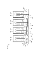
- FIG. 2 is a diagram illustrating a battery cooling unit shown in FIG. 1;
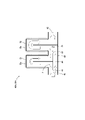
- FIG. 10 is a diagram illustrating a battery cooling unit according to Embodiment 2;
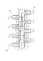
- FIG. 11 is a diagram illustrating a battery cooling unit according to Example 3;
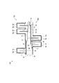
- FIG. 11 is a diagram illustrating a battery cooling unit according to Example 4;
- FIG. 11 is a diagram illustrating a battery cooling unit according to Example 5;
- the battery cooling system 10 is mounted, for example, on a vehicle that uses a motor as a drive source, and is used to cool the battery Ba.
- Battery Ba is used to operate the motor.
- the number of batteries Ba to be cooled may be one, or two or more.
- the battery cooling system 10 includes a refrigerating cycle 20 through which a refrigerant circulates, a cooling water cycle 30 that is thermally coupled to the refrigerating cycle 20 and through which cooling water circulates, and the refrigerating cycle 20 and the cooling water cycle 30 thermally.
- a chiller 13 coupled to and for exchanging heat between the refrigerant and cooling water.
- the refrigerating cycle 20 includes a compressor 21 that compresses and discharges the refrigerant heated in the chiller 13, a radiator 22 that radiates the heat of the refrigerant discharged from the compressor 21, and a liquid at the radiator 22. It has a receiver tank 23 for storing liquid refrigerant and a decompression device 24 for decompressing the refrigerant flowing out from the radiator 22 and flowing it to the chiller 13 .
- the refrigerating cycle 20 may have an accumulator (not shown) between the chiller 13 and the compressor 21 instead of the receiver tank 23 .
- the receiver tank 23 may be provided integrally with the radiator 22 .
- the compressor 21, the radiator 22, the receiver tank 23, and the decompression device 24 are connected via a refrigerant channel 25 through which the refrigerant flows.
- the coolant circulates through the coolant channel 25 .
- the refrigerating cycle 20 may have, for example, a branch circuit (not shown) so as to cool the interior of the vehicle.
- a fan 22a can be provided in the vicinity of the radiator 22, for example, to force air to flow and promote heat dissipation of the refrigerant.
- the chiller 13 serves as a heat exchanger that cools the cooling water circulating in the cooling water cycle 30.
- the cooling water cycle 30 includes a pump 31 for pumping cooling water, and a battery cooling unit 40 (hereinafter abbreviated as "cooling unit 40") into which the water cooled in the chiller 13 flows to cool the battery Ba. have.
- the pump 31 and the battery cooling unit 40 are connected via a cooling water channel 33 through which cooling water can flow. Cooling water circulates through the pump 31 and the battery cooling unit 40 .
- the battery Ba can be cooled by refrigerant or oil in addition to cooling water. These cooling water, coolant, and oil can be said to be a heat medium for cooling the battery Ba.
- cooling water when cooling water is used as the heat medium, it is preferable to mix antifreeze components such as ethylene glycol and antirust components. Damage to the cooling water cycle 30 and the cooling unit 40 due to freezing and corrosion of the cooling water can be prevented.
- oil when used as the heat medium, it preferably has a lower melting point than water. The cooling water cycle 30 can be operated even when the outside air temperature is below freezing.
- the cooling unit 40 has an inlet 41 through which cooling water flows in from the outside of the cooling unit 40 , an outlet 42 through which cooling water flows out of the cooling unit 40 , and between the inlet 41 and the outlet 42 .
- the cooling unit 40 can integrally form each part by pressing a metal plate.
- the cooling unit 40 can also be formed by connecting different parts.
- the heat exchange portions 51 to 54 and the distribution channel 60 having the inlet 41 and the outlet 42 may be manufactured and connected.
- the cooling unit 40 is preferably manufactured by pressing an aluminum alloy to form a lower plate and an upper plate, sticking them together to form a temporary assembly, and connecting them by a brazing method.
- the heat exchange parts 51 to 54 allow cooling water to flow through them, and their outer peripheral surfaces are in contact with the battery Ba.
- the heat exchange units 51 to 54 cool the battery Ba by heat exchange between cooling water flowing inside and the battery Ba in contact with the outside.
- the heat exchange units 51 to 54 are arranged in the order of the first heat exchange unit 51, the second heat exchange unit 52, and the third heat exchange unit 53 from the upstream side to the downstream side with reference to the direction of flow of the cooling water. It is arranged up to the part 54 .
- the first heat exchange section 51 is arranged adjacent to the upstream side of the second heat exchange section 52 .
- the first heat exchange section 51 may be referred to as an upstream heat exchange section 51 arranged adjacent to the second heat exchange section 52 on the upstream side of the second heat exchange section 52 .
- the second heat exchange section 52 may be referred to as a downstream heat exchange section 52 arranged downstream of the upstream heat exchange section 51 with respect to the first heat exchange section 51 .
- the upstream heat exchange section and the downstream heat exchange section are relatively determined by the positions of the heat exchange sections 51-54.
- the second heat exchange section 52 can be called an upstream heat exchange section 52 with respect to the third heat exchange section 53
- the third heat exchange section 53 can be called a downstream heat exchange section 52 with respect to the second heat exchange section 52 . It can be called an exchange unit 53 .
- the third heat exchange section 53 can be said to be an upstream heat exchange section 53 with respect to the fourth heat exchange section 54
- the fourth heat exchange section 54 is downstream with respect to the third heat exchange section 53 . It can be called a heat exchange section 54 .
- upstream heat exchange sections 51-53 and downstream heat exchange sections 52-54 may be collectively referred to as upstream heat exchange sections 51-53 and downstream heat exchange sections 52-54.
- the distribution flow path 60 includes a first branch portion 61 that branches part of the cooling water that has flowed in from the inlet 41 , and directs the branched cooling water at the first branch portion 61 toward the first heat exchange portion 51 .
- a first junction 81 that flows into the heat exchange portion 52;
- a part of the cooling water flowing through the detour 66 joins the cooling water that has flowed through the second heat exchanging portion 52 to join the second introducing passage 72 that flows the cooled water toward the second heat exchanging portion 52 .
- 3 a second junction 82 that flows into the heat exchanging portion 53;
- a third confluence portion 83 that flows into the heat exchange portion 54
- a fourth introduction passage 74 that flows the cooling water merged in the third confluence portion 83 toward the fourth heat exchange portion 54 .
- the first to third introduction paths 71 to 73 are sometimes referred to as introduction paths 71 to 73.
- the introduction paths 71-73 flow part of the cooling water that has flowed in from the inlet 41 toward the upstream heat exchange sections 51-53.
- the fourth introduction path 74 allows all of the cooling water that has flowed in from the inlet 41 to flow toward the fourth heat exchange section 54 (downstream heat exchange section 54). 73 is different.
- the first to third branch portions 61 to 63 are sometimes referred to as branch portions 61 to 63.
- the branch portions 61 to 63 branch the cooling water into introduction paths 71 to 73 and a detour path 66 that bypasses the upstream heat exchange portions 51 to 53 .
- junctions 81-83 are sometimes referred to as junctions 81-83.
- the confluence sections 81 to 83 merge part or all of the heat medium flowing through the detour 66 with the heat medium that has flowed through the upstream heat exchange sections 51 to 53 and flow it to the downstream heat exchange sections 52 to 54 .
- a refrigerant circulates in the refrigerating cycle 20 .
- the refrigerant is compressed in the compressor 21 and discharged in a high-temperature and high-pressure state.
- the discharged refrigerant is cooled and condensed by heat exchange with the atmosphere when passing through the radiator 22 .
- the refrigerant After passing through the radiator 22 , the refrigerant is separated into gas and liquid in the receiver tank 23 , and the liquid refrigerant flows to the decompression device 24 .
- the refrigerant is decompressed in the decompression device 24 to be in a state of gas-liquid mixture, low temperature and low pressure.
- the low-temperature, low-pressure refrigerant cools the cooling water by heat exchange with the cooling water when passing through the chiller 13 .
- Refrigerant obtained by cooling the cooling water (refrigerant heated by the cooling water and gaseous) flows from the chiller 13 toward the compressor 21 .
- cooling water circulates in the cooling water cycle 30 .
- Cooling water is pumped by a pump 31 and circulated through a cooling water flow path 33 .
- Cooling water discharged from the pump 31 flows through the chiller 13 .
- the cooling water is cooled by the refrigerant as it flows through the chiller 13 .
- the cooled cooling water passes through the cooling unit 40 .
- the cooling water cools the battery Ba by heat exchange with the battery Ba.
- the cooling water that has cooled the battery Ba flows from the cooling unit 40 toward the pump 31 .
- a portion of the cooling water that has flowed in from the inlet 41 is branched at the first branch portion 61 and flows into the first introduction passage 71 .
- the cooling water introduced into the first introduction path 71 flows through the first heat exchange portion 51 and cools the battery Ba.
- the cooling water that has passed through the first heat exchanging portion 51 and whose temperature has risen flows toward the second introduction passage 72 .
- part of the low-temperature cooling water that flows through the detour 66 joins the second introduction path 72 via the first junction section 81 .
- a portion of the cooling water flowing through the detour 66 is branched toward the second introduction passage 72 at the second branch portion 62 .
- the cooling water introduced into the second introduction passage 72 flows through the second heat exchange portion 52 and cools the battery Ba.
- the cooling water that has passed through the second heat exchanging portion 52 and whose temperature has risen flows toward the third introduction passage 73 .
- part of the low-temperature cooling water that flows through the detour 66 joins the third introduction passage 73 via the second junction section 82 .
- a portion of the cooling water flowing through the detour 66 is branched toward the third introduction passage 73 at the third branch portion 63 .
- the cooling water introduced into the third introduction passage 73 flows through the third heat exchange portion 53 and cools the battery Ba.
- the cooling water that has passed through the third heat exchanging portion 53 and whose temperature has risen flows toward the fourth introduction passage 74 .
- the flow rate of the cooling water flowing in from the inflow port 41 is Q [L / s], and the flow rate of the cooling water introduced into the first heat exchange section 51 and the second to fourth heat exchanges distributed from the detour 66
- the flow rate of the cooling water introduced into the first introduction passage 71 is Q/4 [L/s]. That is, under the above conditions, when the number of heat exchange units 51 to 54 provided is N, the flow rate of cooling water introduced into the first introduction passage 71 is Q/N [L/s ] becomes.
- the flow rate of the cooling water branched at the first branch portion 61 and flowing to the detour 66 is (3 ⁇ Q)/4 [L/s].
- the temperature T1 [K] of the cooling water flowing into the first heat exchanging portion 51 from the first introduction passage 71 is substantially the same as the temperature T0 [K] of the cooling water flowing from the inlet 41 .
- the flow rate of cooling water that joins at the first confluence portion 81 is substantially the same as the flow rate of cooling water that has passed through the first heat exchange portion 51 .
- the flow rate of cooling water in the second introduction passage 72 is (2 ⁇ Q)/N [L/s] becomes.
- the flow rate of the cooling water branched at the second branch portion 62 and flowing to the detour 66 is Q/2 [L/s].
- the temperature T2 [K] of the cooling water that joins at the first joining portion 81 and is introduced into the second introduction passage 72 can be expressed as follows.
- the cooling water flowing into the second heat exchange section 52 has a temperature rise of t/2 [K] compared to the cooling water flowing into the first heat exchange section 51, while the flow rate is Q/4 [L/ s] increases.
- the flow rate of the cooling water introduced into the third introduction passage 73 increases by Q/4 [L/s] from the flow rate of the cooling water that has passed through the second heat exchange section 52. , 3Q/4 [L/s].
- the flow rate of cooling water in the third introduction passage 73 is (3 ⁇ Q)/N [L/s].
- the flow rate of the cooling water branched at the third branching portion 63 and flowing to the detour 66 is Q/4 [L/s].
- the temperature T3 [K] of the cooling water that joins at the second joining portion 82 and is introduced into the third introduction passage 73 can be expressed as follows.
- the cooling water flowing into the third heat exchange section 53 has a temperature rise of t/6 [K] compared to the cooling water flowing into the second heat exchange section 52, while the flow rate is Q/4 [L/ s] increases.
- the flow rate of cooling water introduced into the fourth introduction passage 74 is Q [L/s].
- the flow rate of cooling water in the fourth introduction passage 74 (Nth introduction passage 74) is Q [L/s]. That is, it becomes the same as the flow rate of the cooling water at the inlet 41 .
- the temperature T4 [K] of the cooling water that joins at the third joining portion 83 and is introduced into the fourth introduction passage 74 can be expressed as follows.
- the cooling water flowing into the fourth heat exchange section 54 has a temperature rise of t/12 [K] compared to the cooling water flowing into the third heat exchange section 53, while the flow rate is Q/4 [L/ s] increases.
- the battery cooling unit 40 merges the cooling water having substantially the same temperature as the temperature of the cooling water at the inlet 41, and then introduces the cooling water into the second to fourth heat exchange portions 52-54. Therefore, the cooling water having cooling performance can be reliably supplied to all the heat exchange portions 51-54. Further, the cooling water flowing into each of the heat exchanging parts 51 to 54 has a higher temperature at the time of inflow and an increased flow rate as it goes downstream. That is, the cooling water flowing into the downstream heat exchanging portion (eg, the fourth heat exchanging portion 54) is relatively higher than the cooling water flowing into the upstream heat exchanging portion (eg, the third heat exchanging portion 53). The battery Ba can be sufficiently cooled by increasing the flow rate even though the temperature is already rising.
- the cooling water flowing into the upstream heat exchanging portion (eg, the first heat exchanging portion 51) is relatively higher than the cooling water flowing into the downstream heat exchanging portion (eg, the second heat exchanging portion 52).
- the flow rate is small, the battery Ba can be sufficiently cooled because there is no (small) rise in temperature. Therefore, the battery Ba can be sufficiently and uniformly cooled in all the heat exchange portions from the upstream side to the downstream side.
- the cooling unit 40 described above will be summarized.
- the cooling unit 40 includes an inflow port 41, an outflow port 42, a plurality of heat exchange units 51 to 54 thermally connected to the battery Ba, and a heat medium flowing in from the inflow port 41 to the plurality of heat exchange units 51 to 54. and a distribution channel 60 that distributes to 54 .
- the heat exchange units 51 to 54 are arranged from the upstream side to the downstream side with respect to the direction in which the cooling water flows.
- the fourth heat exchange section 54 (the Nth heat exchange section 54) is arranged in the order of the section 51 and the second heat exchange section 52 .
- the distribution channel 60 has a first branch portion 61 that branches the channel into a first introduction channel 71 and a bypass channel 66 .
- the distribution flow path 60 joins part of the heat medium flowing through the detour 66 to the cooling water that has flowed through the first heat exchange section 51, and flows it to the second heat exchange section 52 from the first confluence section 81, All of the cooling water flowing through the detour 66 is merged with the cooling water flowing through the third heat exchanging portion 53 ((N-1)th heat exchanging portion 53), and the fourth heat exchanging portion 54 (Nth heat exchanging portion 54), and three ((N ⁇ 1)) junctions 81 to 83 up to a third junction 83 ((N ⁇ 1)th junction 83).
- the distribution channel 60 is a detour that bypasses the introduction channels 71 to 73 and the upstream heat exchange units 51 to 53 to flow part of the cooling water that has flowed in from the inlet 41 toward the upstream heat exchange units 51 to 53. It has branching portions 61 to 63 that branch into a path 66 . In addition, there are confluence portions 81 to 83 in which part or all of the cooling water flowing through the detour 66 is merged with the cooling water flowing through the upstream heat exchanging portions 51 to 53 and flowed to the downstream heat exchanging portions 52 to 54. .
- the cooling unit 40 described above has the following effects.
- the cooling unit 40 has a distribution channel 60 that distributes the cooling water that has flowed in from the inlet 41 to the plurality of heat exchange parts 51-54. Specifically, the cooling water that has flowed in from the inlet 41 is distributed by the branch portions 61 to 63, and part of it flows toward the upstream heat exchange portions 51 to 53 via the introduction paths 71 to 73, and the rest is bypassed. It flows to the downstream side of the upstream heat exchange sections 51 to 53 via the passage 66 . A heat medium with high cooling performance is flowed to the upstream heat exchange parts 51 to 53, and the cooling water with high cooling performance is joined to the cooling water whose cooling performance has decreased after passing through the upstream heat exchange parts 51 to 53, It flows to the downstream heat exchange sections 52-54.
- the cooling performance on the upstream side and the downstream side can be made uniform compared to the case where the entire amount of cooling water is flowed in series to the upstream heat exchange sections 51 to 53 and the downstream heat exchange sections 52 to 54 .
- the cooling unit 40 uses cooling water as a heat medium and is preferably used as a part of the battery cooling system 10 combined with the refrigeration cycle 20 .
- Flowing liquid cooling water facilitates distribution of the cooling water to the introduction channels 71 to 73 and the detour 66 in the distribution channel 60 at an intended ratio.
- heat energy recovered from the battery Ba is discharged from the radiator 22 of the refrigerating cycle 20 to the outside of the cooling system. can do.
- the flow rate of high-cooling (low-temperature) cooling water added from the first heat exchange section 51 to the fourth heat exchange section 54 (Nth heat exchange section 54) is the same.
- the entire battery Ba and/or each of the plurality of batteries Ba can be cooled more uniformly.
- Example 2 a cooling unit 40A according to Embodiment 2 will be described with reference to the drawings.
- the basic configuration of the cooling unit 40A is common to the cooling unit 40 (see FIG. 2) according to the first embodiment. Reference numerals are used for parts that are common to the first embodiment, and detailed descriptions thereof are omitted.
- the cooling unit 40A is composed of two heat exchanging parts 51 and 52 .
- the first heat exchange section 51 is the upstream heat exchange section 51 and the second heat exchange section 52 is the downstream heat exchange section 52 .
- the first branch portion 61 includes a first introduction passage 71 that flows a part of the cooling water that has flowed in from the inlet 41 toward the upstream heat exchange portion 51, a detour passage 66 that bypasses the upstream heat exchange portion 51, branch the flow path to
- the first merging section 81 joins all of the cooling water flowing through the detour 66 to the cooling water that has flowed through the upstream heat exchange section 51 and flows it to the downstream heat exchange section 52 .
- the cooling unit 40A described above and the battery cooling system 10A equipped with this cooling unit 40A also exhibit the predetermined effects of the present invention.
- Example 3 a cooling unit 40B according to Embodiment 3 will be described with reference to the drawings.
- the basic configuration of the cooling unit 40B is common to the cooling unit 40 (see FIG. 2) according to the first embodiment. Reference numerals are used for parts that are common to the first embodiment, and detailed descriptions thereof are omitted.
- FIG. 4 Two sets of cooling units 40B are integrally provided facing each other in the battery cooling system 10B. These cooling units 40B share the inflow port 41, the outflow port 42, and the distribution channel 60. As shown in FIG.
- the two sets of cooling units 40B each have four heat exchange parts 51-54. With respect to the flow direction of the cooling water, the heat exchanging parts 51 to 54 are offset from each other, and the heat exchanging parts 51 to 54 of each set are alternately arranged.
- the cooling unit 40B described above and the battery cooling system 10B equipped with this cooling unit 40B also exhibit the predetermined effects of the present invention.
- Example 4 a cooling unit 40C according to Embodiment 4 will be described with reference to the drawings.
- the basic configuration of the cooling unit 40C is common to that of the cooling unit 40B (see FIG. 4) according to the third embodiment.
- reference numerals are used and detailed descriptions are omitted.
- cooling units 40C are integrally provided facing each other. These cooling units 40 ⁇ /b>C share the inlet 41 , outlet 42 and distribution channel 60 .
- the heat exchange portions 51 to 53 are offset from each other with respect to the flow direction of the cooling water.
- the heat exchange portions 51 to 53 of each set are not arranged alternately. That is, it includes a portion where one set of heat exchange portions 51 and 52 is arranged in succession.
- the cooling unit 40C described above and the battery cooling system 10C equipped with this cooling unit 40C also exhibit the predetermined effects of the present invention.
- Example 5 a cooling unit 40D according to Example 5 will be described with reference to the drawings.
- the basic configuration of the cooling unit 40D is common to the cooling unit 40 (see FIG. 2) according to the first embodiment. Reference numerals are used for parts that are common to the first embodiment, and detailed descriptions thereof are omitted.
- the cooling unit 40D may be composed of multiple parts. More specifically, tubular connection pipes 67 and 68 that connect a plurality of components so as to allow flow constitute part of the distribution channel 60D.
- the cooling unit 40D described above and the battery cooling system 10D equipped with this cooling unit 40D also exhibit the predetermined effects of the present invention.
- cooling unit is not limited to being mounted on a hybrid vehicle, but can also be mounted on an electric vehicle, a saddle-ride type vehicle using a motor, vehicles other than vehicles, construction machinery, and the like.
- the cooling unit when a refrigerant is used as the heat medium, it is possible to arrange the cooling unit directly on the refrigeration cycle. Also, the cooling unit can be provided independently without sharing a part of the air conditioner.
- the cooling unit has two and four heat exchange units
- the number of heat exchange units may be any number as long as a plurality of heat exchange units are provided. good. In other words, it is possible to provide three heat exchange units, or five or more heat exchange units.
- the cooling unit can be arranged not only on the bottom surface of the battery Ba, but also on the side surface or top surface. It is also possible to cool one side of the battery or to cool multiple sides using multiple cooling units.
- the flow rate of the cooling water introduced into the downstream heat exchange sections 52 to 54 increases relative to the cooling water that has passed through the heat exchange sections 51 to 53 on the upstream side by one. has been described as being substantially the same as the flow rate of the cooling water introduced into the first heat exchange section 51, but it is also possible to vary the increased flow rate of the cooling water.
- the third heat exchange unit 53 is The flow rate of the cooling water flowing through the fourth heat exchange section 54, which increases with respect to the passing cooling water, is the flow rate of the cooling water introduced into the first heat exchange section 51, the flow rate of the cooling water introduced into the first heat exchange section 51, and the flow rate of the cooling water being distributed from the detour 66 to the second heat exchange section. It is preferable to increase the flow rate of the cooling water introduced into 52 and the flow rate of cooling water distributed from the detour 66 and introduced into the third heat exchange section 53 .
- the flow rate of the cooling water (the cooling water that does not increase in temperature and has a high cooling capacity) that flows through the detour 66 and is introduced into the fourth heat exchange section 54 is is increased, the cooling performance of the battery Ba, which generates a large amount of heat, can be ensured, and the entire battery Ba can be uniformly cooled.
- the present invention is not limited to the examples.
- the cooling unit of the present invention is suitable for cooling batteries used in vehicles.
- Third branch portion (branch portion) 66... Detour route 71... First introduction route (introduction route) 72... Second introduction path (introduction path) 73... Third introduction path (introduction path) 81... First junction (junction) 82 Second junction (junction) 83... Third junction (junction) Ba...Battery
Landscapes
- Engineering & Computer Science (AREA)
- Manufacturing & Machinery (AREA)
- General Chemical & Material Sciences (AREA)
- Electrochemistry (AREA)
- Chemical Kinetics & Catalysis (AREA)
- Chemical & Material Sciences (AREA)
- Mechanical Engineering (AREA)
- Power Engineering (AREA)
- Transportation (AREA)
- Thermal Sciences (AREA)
- Physics & Mathematics (AREA)
- Life Sciences & Earth Sciences (AREA)
- Sustainable Energy (AREA)
- Sustainable Development (AREA)
- General Engineering & Computer Science (AREA)
- Secondary Cells (AREA)
Abstract
Description
このバッテリ冷却ユニット(40;40A;40B;40C;40D)の外部から熱媒体が流入する流入口(41)と、前記バッテリ冷却ユニット(40;40A;40B;40C;40D)の外部へ熱媒体が流出する流出口(42)と、前記バッテリ(Ba)に熱的に接続される複数の熱交換部(51~54)と、前記流入口(41)から流入した熱媒体を前記複数の熱交換部(51~54)に分配する分配流路(60)と、を備え、
前記熱交換部(51~54)のうち、任意の2つの前記熱交換部(51~54)を、前記熱媒体の流れる方向を基準として、上流側熱交換部(51~53)、この上流側熱交換部(51~53)よりも下流側に配置されている下流側熱交換部(52~54)、とした場合に、
前記分配流路(60)は、
前記流入口(41)から流入した熱媒体の一部を前記上流側熱交換部(51~53)に向けて流す導入路(71~73)と前記上流側熱交換部(51~53)を迂回する迂回路(66)とに分岐する分岐部(61~63)と、
前記上流側熱交換部(51~53)を通流した熱媒体に前記迂回路(66)を流れる熱媒体の一部又は全部を合流させて前記下流側熱交換部(52~54)に流す合流部(81~83)と、を有するバッテリ冷却ユニット(40;40A;40B;40C;40D)が提供される。
このバッテリ冷却ユニット(40;40B;40C)の外部から熱媒体が流入する流入口(41)と、前記バッテリ冷却ユニット(40;40B;40C)の外部へ熱媒体が流出する流出口(42)と、前記バッテリ(Ba)に熱的に接続される複数の熱交換部(51~54)に分配する分配流路(60)と、を備え、
前記熱交換部(51~54)の設けられる数をN個とした場合に、前記熱媒体の流れる方向を基準として、上流側から下流側に、第1熱交換部(51)、第2熱交換部(52)の順に第N熱交換部(54)まで配置され、
前記分配流路(60)は、
前記流入口(41)から流入した熱媒体の一部を前記第1熱交換部(51)に向けて流す第1導入路(71~73)と前記第1熱交換部(51)を迂回する迂回路(66)とに分岐する第1分岐部(61~63)と、
前記第1熱交換部(51)を通流した熱媒体に前記迂回路(66)を流れる熱媒体の一部を合流させて前記第2熱交換部(52)に流す第1合流部(81)から、前記第(N-1)熱交換部(53)を通流した熱媒体に前記迂回路(66)を流れる熱媒体の全部を合流させて前記第N熱交換部(54)に流す第(N-1)合流部(83)までの、(N-1)個の合流部(81~83)と、を有する、バッテリ冷却ユニット(40;40B;40C)が提供される。
図1を参照する。バッテリ冷却システム10は、例えば、モータを駆動源として用いる車両に搭載され、バッテリBaを冷却するために用いられる。バッテリBaは、モータを作動させるために用いられる。冷却されるバッテリBaの数は、1つであっても良いし、2個以上の複数であっても良い。
次に、実施例2による冷却ユニット40Aを図面に基づいて説明する。冷却ユニット40Aの基本的な構成については、実施例1による冷却ユニット40(図2参照)と共通する。実施例1と共通する部分については、符号を流用すると共に、詳細な説明を省略する。
次に、実施例3による冷却ユニット40Bを図面に基づいて説明する。冷却ユニット40Bの基本的な構成については、実施例1による冷却ユニット40(図2参照)と共通する。実施例1と共通する部分については、符号を流用すると共に、詳細な説明を省略する。
次に、実施例4による冷却ユニット40Cを図面に基づいて説明する。冷却ユニット40Cの基本的な構成については、実施例3による冷却ユニット40B(図4参照)と共通する。実施例1及び/又は実施例3と共通する部分については、符号を流用すると共に、詳細な説明を省略する。
次に、実施例5による冷却ユニット40Dを図面に基づいて説明する。冷却ユニット40Dの基本的な構成については、実施例1による冷却ユニット40(図2参照)と共通する。実施例1と共通する部分については、符号を流用すると共に、詳細な説明を省略する。
13…チラー
20…冷凍サイクル
21…圧縮機
22…放熱器
24…減圧装置
30…冷却水サイクル
31…ポンプ
40、40A、40B、40C、40D…バッテリ冷却ユニット
41…流入口
42…流出口
51…第1熱交換部(上流側熱交換部)
52…第2熱交換部(下流側熱交換部、上流側熱交換部)
53…第3熱交換部(下流側熱交換部、上流側熱交換部)
54…第4熱交換部(下流側熱交換部、第N熱交換部)
60…分配流路
61…第1分岐部(分岐部)
62…第2分岐部(分岐部)
63…第3分岐部(分岐部)
66…迂回路
71…第1導入路(導入路)
72…第2導入路(導入路)
73…第3導入路(導入路)
81…第1合流部(合流部)
82…第2合流部(合流部)
83…第3合流部(合流部)
Ba…バッテリ
Claims (4)
- 熱媒体によりバッテリ(Ba)を冷却可能なバッテリ冷却ユニット(40;40A;40B;40C;40D)であって、
このバッテリ冷却ユニット(40;40A;40B;40C;40D)の外部から熱媒体が流入する流入口(41)と、前記バッテリ冷却ユニット(40;40A;40B;40C;40D)の外部へ熱媒体が流出する流出口(42)と、前記バッテリ(Ba)に熱的に接続される複数の熱交換部(51~54)と、前記流入口(41)から流入した熱媒体を前記複数の熱交換部(51~54)に分配する分配流路(60)と、を備え、
前記熱交換部(51~54)のうち、任意の2つの前記熱交換部(51~54)を、前記熱媒体の流れる方向を基準として、上流側熱交換部(51~53)、この上流側熱交換部(51~53)よりも下流側に配置されている下流側熱交換部(52~54)、とした場合に、
前記分配流路(60)は、
前記流入口(41)から流入した熱媒体の一部を前記上流側熱交換部(51~53)に向けて流す導入路(71~73)と前記上流側熱交換部(51~53)を迂回する迂回路(66)とに分岐する分岐部(61~63)と、
前記上流側熱交換部(51~53)を通流した熱媒体に前記迂回路(66)を流れる熱媒体の一部又は全部を合流させて前記下流側熱交換部(52~54)に流す合流部(81~83)と、を有するバッテリ冷却ユニット(40;40A;40B;40C;40D)。 - 熱媒体によりバッテリ(Ba)を冷却可能なバッテリ冷却ユニット(40;40B;40C)であって、
このバッテリ冷却ユニット(40;40B;40C)の外部から熱媒体が流入する流入口(41)と、前記バッテリ冷却ユニット(40;40B;40C)の外部へ熱媒体が流出する流出口(42)と、前記バッテリ(Ba)に熱的に接続される複数の熱交換部(51~54)に分配する分配流路(60)と、を備え、
前記熱交換部(51~54)の設けられる数をN個とした場合に、前記熱媒体の流れる方向を基準として、上流側から下流側に、第1熱交換部(51)、第2熱交換部(52)の順に第N熱交換部(54)まで配置され、
前記分配流路(60)は、
前記流入口(41)から流入した熱媒体の一部を前記第1熱交換部(51)に向けて流す第1導入路(71~73)と前記第1熱交換部(51)を迂回する迂回路(66)とに分岐する第1分岐部(61~63)と、
前記第1熱交換部(51)を通流した熱媒体に前記迂回路(66)を流れる熱媒体の一部を合流させて前記第2熱交換部(52)に流す第1合流部(81)から、前記第(N-1)熱交換部(53)を通流した熱媒体に前記迂回路(66)を流れる熱媒体の全部を合流させて前記第N熱交換部(54)に流す第(N-1)合流部(83)までの、(N-1)個の合流部(81~83)と、を有する、バッテリ冷却ユニット(40;40B;40C)。 - 前記第1導入路(71~73)から前記第1熱交換部(51)に導入される熱媒体の量と、前記迂回路(66)から分配されて前記第2熱交換部(52)から前記第N熱交換部(54)までのそれぞれの前記熱交換部(52~54)に合流される熱媒体の量とは、略同じである、請求項2に記載のバッテリ冷却ユニット(40;40B;40C)。
- 請求項1乃至3何れか1項に記載のバッテリ冷却ユニット(40;40A;40B;40C;40D)が搭載されているバッテリ冷却システム(10)であって、
このバッテリ冷却システム(10)は、冷媒が循環する冷凍サイクル(20)と、前記冷凍サイクル(20)と熱的に結合し冷却水が循環する冷却水サイクル(30)と、これらの冷凍サイクル(20)と冷却水サイクル(30)とを熱的に結合し冷媒と冷却水との熱交換を行うチラー(13)と、を備え、
前記冷凍サイクル(20)は、前記チラー(13)において加熱された冷媒を圧縮し吐出する圧縮機(21)と、前記圧縮機(21)から吐出された冷媒を放熱する放熱器(22)と、前記放熱器(22)から流出した冷媒を減圧する減圧装置(24)と、を有し、
前記冷却水サイクル(30)は、冷却水を圧送するポンプ(31)と、前記チラー(13)において冷却された水が流入し前記バッテリ(Ba)を冷却する前記バッテリ冷却ユニット(40;40A;40B;40C;40D)と、を有する、バッテリ冷却システム(10)。
Priority Applications (4)
| Application Number | Priority Date | Filing Date | Title |
|---|---|---|---|
| JP2023525742A JPWO2022255159A1 (ja) | 2021-05-31 | 2022-05-24 | |
| EP22815909.1A EP4350845A4 (en) | 2021-05-31 | 2022-05-24 | BATTERY COOLING UNIT AND SYSTEM |
| US18/565,523 US20240375475A1 (en) | 2021-05-31 | 2022-05-24 | Battery cooling unit and battery cooling system |
| CN202280008317.2A CN116648811A (zh) | 2021-05-31 | 2022-05-24 | 电池冷却单元及电池冷却系统 |
Applications Claiming Priority (2)
| Application Number | Priority Date | Filing Date | Title |
|---|---|---|---|
| JP2021090797 | 2021-05-31 | ||
| JP2021-090797 | 2021-05-31 |
Publications (1)
| Publication Number | Publication Date |
|---|---|
| WO2022255159A1 true WO2022255159A1 (ja) | 2022-12-08 |
Family
ID=84323151
Family Applications (1)
| Application Number | Title | Priority Date | Filing Date |
|---|---|---|---|
| PCT/JP2022/021192 Ceased WO2022255159A1 (ja) | 2021-05-31 | 2022-05-24 | バッテリ冷却ユニット、及び、バッテリ冷却システム |
Country Status (5)
| Country | Link |
|---|---|
| US (1) | US20240375475A1 (ja) |
| EP (1) | EP4350845A4 (ja) |
| JP (1) | JPWO2022255159A1 (ja) |
| CN (1) | CN116648811A (ja) |
| WO (1) | WO2022255159A1 (ja) |
Cited By (2)
| Publication number | Priority date | Publication date | Assignee | Title |
|---|---|---|---|---|
| WO2023248989A1 (ja) * | 2022-06-20 | 2023-12-28 | ニデック株式会社 | 冷却装置および半導体装置 |
| WO2026018871A1 (ja) * | 2024-07-18 | 2026-01-22 | 株式会社Aescジャパン | 電池パック |
Citations (5)
| Publication number | Priority date | Publication date | Assignee | Title |
|---|---|---|---|---|
| JP2013055056A (ja) * | 2011-09-01 | 2013-03-21 | Sb Limotive Co Ltd | バッテリーパック |
| JP2014026734A (ja) * | 2012-07-24 | 2014-02-06 | Toyota Industries Corp | 電池モジュール及び車両 |
| JP2014033015A (ja) * | 2012-08-01 | 2014-02-20 | Toyota Industries Corp | 冷却器 |
| JP2019212744A (ja) * | 2018-06-05 | 2019-12-12 | 三菱電機株式会社 | 冷却機構 |
| JP2020159612A (ja) * | 2019-03-26 | 2020-10-01 | 株式会社デンソー | 熱輸送システム |
Family Cites Families (9)
| Publication number | Priority date | Publication date | Assignee | Title |
|---|---|---|---|---|
| JPH11329518A (ja) * | 1998-05-21 | 1999-11-30 | Toshiba Battery Co Ltd | 電池装置 |
| JP4827558B2 (ja) * | 2006-02-28 | 2011-11-30 | 三洋電機株式会社 | 車両用の電源装置 |
| CN102656740B (zh) * | 2009-12-25 | 2015-11-25 | 法雷奥日本株式会社 | 蓄电池温度调节系统的安全装置 |
| CN107403975B (zh) * | 2017-07-21 | 2019-09-27 | 精进电动科技股份有限公司 | 一种储能电池液冷系统均流装置和方法 |
| KR102463192B1 (ko) * | 2017-11-30 | 2022-11-03 | 현대자동차 주식회사 | 배터리용 열 관리 시스템 |
| CN215299360U (zh) * | 2018-05-30 | 2021-12-24 | 达纳加拿大公司 | 用于电池热调节的热管理系统和热交换器 |
| US11326837B2 (en) * | 2018-06-29 | 2022-05-10 | Dana Canada Corporation | Heat exchanger with internal manifold structure |
| KR102533382B1 (ko) * | 2019-01-09 | 2023-05-19 | 한온시스템 주식회사 | 열관리 시스템 |
| WO2020241431A1 (ja) * | 2019-05-24 | 2020-12-03 | 株式会社ヴァレオジャパン | バッテリー冷却システム |
-
2022
- 2022-05-24 CN CN202280008317.2A patent/CN116648811A/zh active Pending
- 2022-05-24 WO PCT/JP2022/021192 patent/WO2022255159A1/ja not_active Ceased
- 2022-05-24 JP JP2023525742A patent/JPWO2022255159A1/ja active Pending
- 2022-05-24 US US18/565,523 patent/US20240375475A1/en active Pending
- 2022-05-24 EP EP22815909.1A patent/EP4350845A4/en active Pending
Patent Citations (5)
| Publication number | Priority date | Publication date | Assignee | Title |
|---|---|---|---|---|
| JP2013055056A (ja) * | 2011-09-01 | 2013-03-21 | Sb Limotive Co Ltd | バッテリーパック |
| JP2014026734A (ja) * | 2012-07-24 | 2014-02-06 | Toyota Industries Corp | 電池モジュール及び車両 |
| JP2014033015A (ja) * | 2012-08-01 | 2014-02-20 | Toyota Industries Corp | 冷却器 |
| JP2019212744A (ja) * | 2018-06-05 | 2019-12-12 | 三菱電機株式会社 | 冷却機構 |
| JP2020159612A (ja) * | 2019-03-26 | 2020-10-01 | 株式会社デンソー | 熱輸送システム |
Non-Patent Citations (1)
| Title |
|---|
| See also references of EP4350845A4 * |
Cited By (2)
| Publication number | Priority date | Publication date | Assignee | Title |
|---|---|---|---|---|
| WO2023248989A1 (ja) * | 2022-06-20 | 2023-12-28 | ニデック株式会社 | 冷却装置および半導体装置 |
| WO2026018871A1 (ja) * | 2024-07-18 | 2026-01-22 | 株式会社Aescジャパン | 電池パック |
Also Published As
| Publication number | Publication date |
|---|---|
| JPWO2022255159A1 (ja) | 2022-12-08 |
| CN116648811A (zh) | 2023-08-25 |
| EP4350845A4 (en) | 2025-02-26 |
| EP4350845A1 (en) | 2024-04-10 |
| US20240375475A1 (en) | 2024-11-14 |
Similar Documents
| Publication | Publication Date | Title |
|---|---|---|
| JP5775661B2 (ja) | 自動車用加熱、換気、および/または空調装置 | |
| CN103959004B (zh) | 热交换器 | |
| CN112384393B (zh) | 特用于电动车辆的紧凑型热交换器单元和空气调节模块 | |
| WO2022255159A1 (ja) | バッテリ冷却ユニット、及び、バッテリ冷却システム | |
| JP2026053755A (ja) | マニホールド | |
| CN116901648A (zh) | 热管理设备、热管理系统和电动车辆 | |
| CN113665334A (zh) | 一种宽温域的车载散热系统 | |
| JP2019152367A (ja) | 熱交換器ユニットおよびそれを用いた空気調和機 | |
| KR20160131307A (ko) | 열교환기 | |
| CN111114243B (zh) | 用于车辆的冷却模块 | |
| WO2020179651A1 (ja) | 車両用バッテリの冷却モジュール | |
| CN113580872B (zh) | 车辆及其热管理系统 | |
| US6330809B1 (en) | Application of a chiller in an apparatus for cooling a generator/motor | |
| JP2006097911A (ja) | 熱交換器 | |
| US20140157820A1 (en) | Compressor apparatus and refrigerator apparatus | |
| KR20100103891A (ko) | 하이브리드 자동차용 쿨링모듈 | |
| EP1196301A1 (en) | Vehicular /automotive combination compressor and condenser unit | |
| JP7099082B2 (ja) | 機器温調装置 | |
| JP4814823B2 (ja) | 冷凍装置 | |
| JP2006038306A (ja) | 冷凍装置 | |
| JP2019113239A (ja) | 空気調和装置 | |
| JP2006207835A (ja) | 冷凍システム、圧縮放熱装置及び放熱器 | |
| CN115498318A (zh) | 一种电池温度调节系统、新能源汽车及其设备 | |
| CN222451897U (zh) | 车辆热管理系统及车辆 | |
| JP5127858B2 (ja) | 車両用空気調和機 |
Legal Events
| Date | Code | Title | Description |
|---|---|---|---|
| 121 | Ep: the epo has been informed by wipo that ep was designated in this application |
Ref document number: 22815909 Country of ref document: EP Kind code of ref document: A1 |
|
| ENP | Entry into the national phase |
Ref document number: 2023525742 Country of ref document: JP Kind code of ref document: A |
|
| WWE | Wipo information: entry into national phase |
Ref document number: 202280008317.2 Country of ref document: CN |
|
| WWE | Wipo information: entry into national phase |
Ref document number: 2022815909 Country of ref document: EP |
|
| NENP | Non-entry into the national phase |
Ref country code: DE |
|
| ENP | Entry into the national phase |
Ref document number: 2022815909 Country of ref document: EP Effective date: 20240102 |