WO2022255164A1 - 超音波検査装置 - Google Patents
超音波検査装置 Download PDFInfo
- Publication number
- WO2022255164A1 WO2022255164A1 PCT/JP2022/021255 JP2022021255W WO2022255164A1 WO 2022255164 A1 WO2022255164 A1 WO 2022255164A1 JP 2022021255 W JP2022021255 W JP 2022021255W WO 2022255164 A1 WO2022255164 A1 WO 2022255164A1
- Authority
- WO
- WIPO (PCT)
- Prior art keywords
- joint portion
- ultrasonic
- ultrasonic waves
- transmitter
- inspection apparatus
- Prior art date
- Legal status (The legal status is an assumption and is not a legal conclusion. Google has not performed a legal analysis and makes no representation as to the accuracy of the status listed.)
- Ceased
Links
Images


Classifications
-
- G—PHYSICS
- G01—MEASURING; TESTING
- G01N—INVESTIGATING OR ANALYSING MATERIALS BY DETERMINING THEIR CHEMICAL OR PHYSICAL PROPERTIES
- G01N29/00—Investigating or analysing materials by the use of ultrasonic, sonic or infrasonic waves; Visualisation of the interior of objects by transmitting ultrasonic or sonic waves through the object
- G01N29/04—Analysing solids
-
- B—PERFORMING OPERATIONS; TRANSPORTING
- B31—MAKING ARTICLES OF PAPER, CARDBOARD OR MATERIAL WORKED IN A MANNER ANALOGOUS TO PAPER; WORKING PAPER, CARDBOARD OR MATERIAL WORKED IN A MANNER ANALOGOUS TO PAPER
- B31B—MAKING CONTAINERS OF PAPER, CARDBOARD OR MATERIAL WORKED IN A MANNER ANALOGOUS TO PAPER
- B31B70/00—Making flexible containers, e.g. envelopes or bags
- B31B70/006—Controlling; Regulating; Measuring; Safety measures
-
- B—PERFORMING OPERATIONS; TRANSPORTING
- B65—CONVEYING; PACKING; STORING; HANDLING THIN OR FILAMENTARY MATERIAL
- B65B—MACHINES, APPARATUS OR DEVICES FOR, OR METHODS OF, PACKAGING ARTICLES OR MATERIALS; UNPACKING
- B65B51/00—Devices for, or methods of, sealing or securing package folds or closures; Devices for gathering or twisting wrappers, or necks of bags
-
- B—PERFORMING OPERATIONS; TRANSPORTING
- B65—CONVEYING; PACKING; STORING; HANDLING THIN OR FILAMENTARY MATERIAL
- B65B—MACHINES, APPARATUS OR DEVICES FOR, OR METHODS OF, PACKAGING ARTICLES OR MATERIALS; UNPACKING
- B65B57/00—Automatic control, checking, warning, or safety devices
- B65B57/02—Automatic control, checking, warning, or safety devices responsive to absence, presence, abnormal feed, or misplacement of binding or wrapping material, containers, or packages
-
- G—PHYSICS
- G01—MEASURING; TESTING
- G01N—INVESTIGATING OR ANALYSING MATERIALS BY DETERMINING THEIR CHEMICAL OR PHYSICAL PROPERTIES
- G01N29/00—Investigating or analysing materials by the use of ultrasonic, sonic or infrasonic waves; Visualisation of the interior of objects by transmitting ultrasonic or sonic waves through the object
- G01N29/04—Analysing solids
- G01N29/043—Analysing solids in the interior, e.g. by shear waves
-
- G—PHYSICS
- G01—MEASURING; TESTING
- G01N—INVESTIGATING OR ANALYSING MATERIALS BY DETERMINING THEIR CHEMICAL OR PHYSICAL PROPERTIES
- G01N29/00—Investigating or analysing materials by the use of ultrasonic, sonic or infrasonic waves; Visualisation of the interior of objects by transmitting ultrasonic or sonic waves through the object
- G01N29/04—Analysing solids
- G01N29/11—Analysing solids by measuring attenuation of acoustic waves
-
- G—PHYSICS
- G01—MEASURING; TESTING
- G01N—INVESTIGATING OR ANALYSING MATERIALS BY DETERMINING THEIR CHEMICAL OR PHYSICAL PROPERTIES
- G01N29/00—Investigating or analysing materials by the use of ultrasonic, sonic or infrasonic waves; Visualisation of the interior of objects by transmitting ultrasonic or sonic waves through the object
- G01N29/22—Details, e.g. general constructional or apparatus details
-
- G—PHYSICS
- G01—MEASURING; TESTING
- G01N—INVESTIGATING OR ANALYSING MATERIALS BY DETERMINING THEIR CHEMICAL OR PHYSICAL PROPERTIES
- G01N29/00—Investigating or analysing materials by the use of ultrasonic, sonic or infrasonic waves; Visualisation of the interior of objects by transmitting ultrasonic or sonic waves through the object
- G01N29/34—Generating the ultrasonic, sonic or infrasonic waves, e.g. electronic circuits specially adapted therefor
-
- G—PHYSICS
- G01—MEASURING; TESTING
- G01N—INVESTIGATING OR ANALYSING MATERIALS BY DETERMINING THEIR CHEMICAL OR PHYSICAL PROPERTIES
- G01N29/00—Investigating or analysing materials by the use of ultrasonic, sonic or infrasonic waves; Visualisation of the interior of objects by transmitting ultrasonic or sonic waves through the object
- G01N29/36—Detecting the response signal, e.g. electronic circuits specially adapted therefor
-
- B—PERFORMING OPERATIONS; TRANSPORTING
- B31—MAKING ARTICLES OF PAPER, CARDBOARD OR MATERIAL WORKED IN A MANNER ANALOGOUS TO PAPER; WORKING PAPER, CARDBOARD OR MATERIAL WORKED IN A MANNER ANALOGOUS TO PAPER
- B31B—MAKING CONTAINERS OF PAPER, CARDBOARD OR MATERIAL WORKED IN A MANNER ANALOGOUS TO PAPER
- B31B50/00—Making rigid or semi-rigid containers, e.g. boxes or cartons
- B31B50/006—Controlling; Regulating; Measuring; Improving safety
-
- B—PERFORMING OPERATIONS; TRANSPORTING
- B65—CONVEYING; PACKING; STORING; HANDLING THIN OR FILAMENTARY MATERIAL
- B65B—MACHINES, APPARATUS OR DEVICES FOR, OR METHODS OF, PACKAGING ARTICLES OR MATERIALS; UNPACKING
- B65B2220/00—Specific aspects of the packaging operation
- B65B2220/08—Creating fin seals as the longitudinal seal on horizontal or vertical form fill seal [FFS] machines
-
- G—PHYSICS
- G01—MEASURING; TESTING
- G01N—INVESTIGATING OR ANALYSING MATERIALS BY DETERMINING THEIR CHEMICAL OR PHYSICAL PROPERTIES
- G01N2291/00—Indexing codes associated with group G01N29/00
- G01N2291/02—Indexing codes associated with the analysed material
- G01N2291/023—Solids
-
- G—PHYSICS
- G01—MEASURING; TESTING
- G01N—INVESTIGATING OR ANALYSING MATERIALS BY DETERMINING THEIR CHEMICAL OR PHYSICAL PROPERTIES
- G01N2291/00—Indexing codes associated with group G01N29/00
- G01N2291/02—Indexing codes associated with the analysed material
- G01N2291/023—Solids
- G01N2291/0231—Composite or layered materials
-
- G—PHYSICS
- G01—MEASURING; TESTING
- G01N—INVESTIGATING OR ANALYSING MATERIALS BY DETERMINING THEIR CHEMICAL OR PHYSICAL PROPERTIES
- G01N2291/00—Indexing codes associated with group G01N29/00
- G01N2291/04—Wave modes and trajectories
- G01N2291/048—Transmission, i.e. analysed material between transmitter and receiver
-
- G—PHYSICS
- G01—MEASURING; TESTING
- G01N—INVESTIGATING OR ANALYSING MATERIALS BY DETERMINING THEIR CHEMICAL OR PHYSICAL PROPERTIES
- G01N2291/00—Indexing codes associated with group G01N29/00
- G01N2291/04—Wave modes and trajectories
- G01N2291/051—Perpendicular incidence, perpendicular propagation
-
- G—PHYSICS
- G01—MEASURING; TESTING
- G01N—INVESTIGATING OR ANALYSING MATERIALS BY DETERMINING THEIR CHEMICAL OR PHYSICAL PROPERTIES
- G01N2291/00—Indexing codes associated with group G01N29/00
- G01N2291/10—Number of transducers
- G01N2291/102—Number of transducers one emitter, one receiver
-
- G—PHYSICS
- G01—MEASURING; TESTING
- G01N—INVESTIGATING OR ANALYSING MATERIALS BY DETERMINING THEIR CHEMICAL OR PHYSICAL PROPERTIES
- G01N2291/00—Indexing codes associated with group G01N29/00
- G01N2291/10—Number of transducers
- G01N2291/103—Number of transducers one emitter, two or more receivers
-
- G—PHYSICS
- G01—MEASURING; TESTING
- G01N—INVESTIGATING OR ANALYSING MATERIALS BY DETERMINING THEIR CHEMICAL OR PHYSICAL PROPERTIES
- G01N2291/00—Indexing codes associated with group G01N29/00
- G01N2291/10—Number of transducers
- G01N2291/106—Number of transducers one or more transducer arrays
-
- G—PHYSICS
- G01—MEASURING; TESTING
- G01N—INVESTIGATING OR ANALYSING MATERIALS BY DETERMINING THEIR CHEMICAL OR PHYSICAL PROPERTIES
- G01N2291/00—Indexing codes associated with group G01N29/00
- G01N2291/26—Scanned objects
- G01N2291/269—Various geometry objects
- G01N2291/2695—Bottles, containers
-
- G—PHYSICS
- G01—MEASURING; TESTING
- G01N—INVESTIGATING OR ANALYSING MATERIALS BY DETERMINING THEIR CHEMICAL OR PHYSICAL PROPERTIES
- G01N29/00—Investigating or analysing materials by the use of ultrasonic, sonic or infrasonic waves; Visualisation of the interior of objects by transmitting ultrasonic or sonic waves through the object
- G01N29/22—Details, e.g. general constructional or apparatus details
- G01N29/221—Arrangements for directing or focusing the acoustical waves
-
- G—PHYSICS
- G01—MEASURING; TESTING
- G01N—INVESTIGATING OR ANALYSING MATERIALS BY DETERMINING THEIR CHEMICAL OR PHYSICAL PROPERTIES
- G01N29/00—Investigating or analysing materials by the use of ultrasonic, sonic or infrasonic waves; Visualisation of the interior of objects by transmitting ultrasonic or sonic waves through the object
- G01N29/22—Details, e.g. general constructional or apparatus details
- G01N29/223—Supports, positioning or alignment in fixed situation
Definitions
- the present disclosure relates to an ultrasonic inspection apparatus.
- This application claims priority based on Japanese Patent Application No. 2021-090827 filed on May 31, 2021, the entire disclosure of which is incorporated herein.
- Patent Literature 1 discloses an ultrasonic inspection apparatus for inspecting peeling at a joint portion of a container member.
- This type of ultrasonic inspection apparatus has a transmission unit that transmits ultrasonic waves, and receives and analyzes the ultrasonic waves transmitted from the transmission unit and transmitted through the joints to determine whether delamination has occurred in the joints. determine whether or not
- ultrasonic waves are transmitted from a transmission section toward a joint portion in a direction in which edges of container members overlap at the joint portion.
- the joint part of the container member is ultrasonically inspected in a state in which the joint part protrudes from the surface of the predetermined object in a direction perpendicular to the surface.
- the predetermined object is, for example, a non-joint portion of a container member that constitutes the accommodation space of the packaging container, an apparatus that manufactures the packaging container (for example, a pillow packaging machine), or a device that supports the packaging container in a device that conveys the packaging container. It may be a table to do.
- the transmitter when the transmitter is arranged on the surface of the predetermined object so as to transmit the ultrasonic wave in the direction in which the edge of the container member overlaps at the joint portion (that is, the direction along the surface of the predetermined object) as in the conventional art, the transmitter transmits the ultrasonic wave. It is difficult for the ultrasonic waves thus generated to reach the proximal end portion of the joint projecting from the predetermined object, which is positioned on the side of the predetermined object. For this reason, it is difficult for the conventional ultrasonic inspection apparatus to accurately inspect peeling of the container member at the joint portion of the packaging container.
- One example of the object of the present disclosure is to enable accurate inspection of peeling of the container member at the joint even when the joint protrudes from the surface of a predetermined object in a direction orthogonal to the surface.
- An object of the present invention is to provide an ultrasonic inspection apparatus.
- a first aspect of the present disclosure is an ultrasonic inspection apparatus for inspecting a packaging container having a joint portion that is an overlapped and joined edge, wherein the joint portion is perpendicular to the surface from the surface of the object.
- the ultrasonic inspection apparatus is provided with a transmitting section projecting in a direction and irradiating ultrasonic waves toward at least a proximal end portion of the joint portion positioned on the object side.
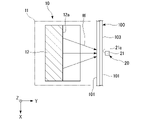
- FIG. 1 is a cross-sectional view schematically showing an ultrasonic inspection apparatus according to a first embodiment
- FIG. 2 is an enlarged cross-sectional view showing an enlarged main part of FIG. 1
- FIG. 3 is a cross-sectional view taken along line III-III of FIG. 2
- FIG. FIG. 3 is a sectional view taken along line IV-IV of FIG. 2
- It is a perspective view which shows typically the modification of the ultrasonic inspection apparatus which concerns on 1st embodiment.
- FIG. 4 is a cross-sectional view schematically showing another usage example of the ultrasonic inspection apparatus according to the first embodiment
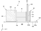
- FIG. 10 is an enlarged cross-sectional view schematically showing a main part of an ultrasonic inspection apparatus according to a second embodiment;
- FIG. 11 is an enlarged cross-sectional view schematically showing a main part of an ultrasonic inspection apparatus according to a third embodiment
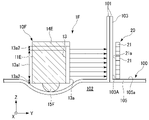
- FIG. 11 is an enlarged cross-sectional view schematically showing a main part of an ultrasonic inspection apparatus according to a fourth embodiment
- FIG. 4 is a cross-sectional view showing another example of a packaging container to be inspected by the ultrasonic inspection apparatus according to the present disclosure
- a packaging container 100 is a container in which a storage space 102 is formed inside by overlapping and joining edges of sheet-like container members 101 .
- the illustrated packaging container 100 is composed of one container member 101, but may be composed of two container members 101, for example.
- the ultrasonic inspection apparatus 1 inspects peeling of the container member 101 at the joint portion 103 of the packaging container 100 where the container member 101 is overlapped and joined.
- the part of the packaging container 100 that forms the accommodation space 102 without being joined among the container members 101 is called a non-joint part 105 .
- the joint portion 103 When inspecting the packaging container 100 with the ultrasonic inspection apparatus 1, the joint portion 103 is protruded from the outer surface 105a (the surface of the predetermined object (object)) of the non-joint portion 105 in a direction orthogonal to the outer surface 105a.
- the projecting direction of the joint portion 103 may not be strictly perpendicular to the outer surface 105a of the non-joint portion 105, and may be slightly inclined.
- the Y-axis direction indicates the direction in which the container member 101 overlaps at the joint portion 103 .
- the direction in which the joint portion 103 protrudes from the outer surface 105a of the non-joint portion 105 is defined as the width direction of the joint portion 103, and is indicated by the Z-axis direction.
- a direction orthogonal to the Z-axis direction and the Y-axis direction is defined as the longitudinal direction of the joint portion 103, and is indicated by the X-axis direction.
- the ultrasonic inspection apparatus 1 includes a transmitting section (transmitter, emitter) 10 and a receiving unit (receiver) 20 .
- the transmitter 10 transmits (irradiates) the ultrasonic waves W toward the joint portion 103 in a state in which the joint portion 103 of the packaging container 100 protrudes in a direction orthogonal to the outer surface 105a of the non-joint portion 105 .
- the transmitter 10 is configured to actively transmit the ultrasonic waves W particularly toward the base end portion 103A of the joint portion 103 located on the non-joint portion 105 side.
- the transmitter 10 of this embodiment has a transmitter body 11 and a mirror 12 .
- the transmitter main body 11 is a part that transmits the ultrasonic waves W.
- the transmitter main body 11 of this embodiment has a transmitter element (irradiation element) 13 and a holding case 14 .
- the transmission element 13 has a transmission surface (irradiation surface) 13a for transmitting the ultrasonic waves W.
- the holding case 14 holds the transmitting element 13 so that the transmitting surface 13a of the transmitting element 13 is exposed to the outside.
- the holding case 14 of this embodiment holds the transmitting element 13 so as to cover the entire periphery of the transmitting surface 13a. That is, the transmitting surface 13 a of the transmitting element 13 is surrounded by a predetermined portion of the holding case 14 .
- the mirror 12 reflects the ultrasonic waves W transmitted from the transmitter body 11 .
- the mirror 12 is arranged so that the ultrasonic wave W reflected by the mirror 12 propagates toward at least the base end portion 103A of the joint portion 103 .
- the mirror 12 of the present embodiment reflects the beam-like ultrasonic waves W transmitted from the inner area 13a1 of the transmission surface 13a of the transmitter main body 11 excluding the peripheral edge area 13a2. That is, the mirror 12 does not reflect the ultrasonic waves W2 transmitted from the peripheral area 13a2 of the transmission surface 13a, but reflects only the ultrasonic waves W1 transmitted from the inner area 13a1 of the transmission surface 13a toward the joint portion 103. Propagate.
- the inner area 13a1 of the transmission surface 13a described above is an area where, for example, the intensity of the transmitted ultrasonic wave W1 is uniform.
- the peripheral region 13a2 of the transmission surface 13a is, for example, a region where the intensity of the transmitted ultrasonic wave W2 is lower than the intensity of the ultrasonic wave W1 transmitted from the inner region 13a1.
- the transmitter body 11 and the mirror 12 of this embodiment will be described more specifically.
- the transmitter main body 11 is arranged on one side of the joint portion 103 in the Y-axis direction (on the left side of the joint portion 103 in FIGS. 1 and 2).
- the transmitting unit body 11 when viewed from the X-axis direction, is arranged such that the ultrasonic waves W project from the transmitting surface 13a of the transmitting unit body 11 toward the non-bonded portion 105 in the opposite direction (Z is arranged to be transmitted in the axial negative direction).
- the mirror 12 is arranged between the transmitter main body 11 and the non-joint portion 105 in the Z-axis direction when viewed from the X-axis direction.
- a reflecting surface 12a of the mirror 12 that reflects the ultrasonic wave W is formed flat.
- the reflecting surface 12a of the mirror 12 faces the transmitting surface 13a of the transmitter main body 11 in the Z-axis direction and faces the joint portion 103 in the Y-axis direction.
- the reflecting surface 12a of the mirror 12 is inclined with respect to the transmission direction (Z-axis negative direction) of the ultrasonic waves W transmitted from the transmitting surface 13a of the transmitter main body 11 and the outer surface 105a of the non-bonded portion 105 .
- the inclination angle of the reflecting surface 12a is 45 degrees.
- the mirror 12 can be arranged with respect to the packaging container 100 so that its reflective surface 12a is located in close proximity to the outer surface 105a of the non-bonded portion 105 in the Z-axis direction.
- the ultrasonic wave W transmitted from the transmission surface 13a of the transmitter main body 11 toward the mirror 12 is reflected by the reflection surface 12a of the mirror 12, and propagates toward the joint portion 103 in the positive direction of the Y axis. , passes through the junction 103 .
- the reflecting surface 12a of the mirror 12 is positioned very close to the outer surface 105a of the non-bonded portion 105, the ultrasonic wave W reflected by the reflecting surface 12a can reach the base end portion 103A of the bonded portion 103. .
- the transmission surface 13a of the transmission unit main body 11 in the present embodiment is formed in an arcuate shape recessed in the Z-axis positive direction when viewed from the Y-axis direction. Further, the transmission surface 13a extends linearly in the Y-axis direction as shown in FIG. Therefore, the shape of the transmission surface 13a viewed in the Y-axis direction does not change regardless of the position in the Y-axis direction. That is, the shape of the transmission surface 13a of this embodiment is similar to a portion of the inner peripheral surface of the cylinder in the circumferential direction.
- the transmission surface 13a is formed as described above, the ultrasonic waves W transmitted from the transmission surface 13a of the transmitter main body 11, as shown in FIG. , but does not converge in the Y-axis direction. Therefore, in the absence of the mirror 12, the ultrasonic wave W transmitted from the transmitting surface 13a of the transmitter main body 11 has a linear shape with a short length in the X-axis direction and a long length in the Y-axis direction at the converged position. becomes.
- the reflective surface 12a of the mirror 12 is positioned in front of the position where the ultrasonic waves W transmitted from the transmitter main body 11 converge. Therefore, as shown in FIG.
- the ultrasonic wave W reflected by the reflecting surface 12a of the mirror 12 and propagating in the positive direction of the Y-axis converges in the X-axis direction toward the positive direction of the Y-axis, and converges in the Z-axis direction. does not converge to As a result, the ultrasonic wave W reflected by the reflecting surface 12a of the mirror 12 becomes linear with a short length in the X-axis direction and a long length in the Z-axis direction at the converged position.
- the receiving unit 20 is arranged so that the joint portion 103 of the packaging container 100 is positioned between the transmitting unit 10 described above.
- the receiving unit 20 receives the ultrasonic wave W that has passed through the joint portion 103 of the packaging container 100 .
- the receiving unit 20 has a plurality of receiving sections 21 .
- Each receiving part 21 has a receiving surface 21 a that receives the ultrasonic wave W transmitted through the joint portion 103 of the packaging container 100 . It is preferable that the area of the receiving surface 21a is small.
- the plurality of receivers 21 are arranged such that the ultrasonic waves W travel from the mirror 12 (transmitter 10) toward the joint portion 103 of the packaging container 100 (positive Y-axis direction). are arranged in an array in a direction intersecting with each other. Specifically, the plurality of receivers 21 are arranged in an array corresponding to the converged linear ultrasonic waves W as described above. That is, the plurality of receivers 21 are arranged in a row in the Z-axis direction. The plurality of receiving units 21 are not necessarily arranged strictly at the position where the ultrasonic wave W converges. may be placed in the same position.
- the plurality of receivers 21 be arranged as close to the position where the ultrasonic waves W converge as possible. As illustrated in FIG. 4, when the ultrasonic waves W converge at or near the joint 103 of the packaging container 100, the plurality of receivers 21 are preferably arranged near the joint 103 in the Y-axis direction.
- the transmission section 10 is arranged so that the ultrasonic waves W are transmitted only through the proximal end portion of the joint portion 103 in the projecting direction.
- the arrangement of the transmitter 10 is not limited to this example.
- the transmitter 10 may be arranged, for example, so as to transmit the entire area from the proximal end to the distal end of the joint portion 103 in the projecting direction.
- the receiving unit 20 (the plurality of receiving parts 21) may be arranged from the proximal end to the distal end of the joint portion 103 in the projecting direction.
- the ultrasonic inspection apparatus 1 of the present embodiment receives and analyzes the ultrasonic wave W transmitted from the transmission unit 10 and transmitted through the joint portion 103 of the packaging container 100 at the reception unit 21, so that the container at the joint portion 103 It is possible to determine whether or not the member 101 is peeled off. Detachment of the presence or absence of delamination in the joint portion 103 is performed, for example, by measuring the waveform of the ultrasonic wave W transmitted through the joint portion 103 to be inspected and received by the receiving unit 21 (inspection target waveform). is compared with the waveform (reference waveform) of the ultrasonic wave W received by the receiving unit 21 after passing through the . For example, the correlation value between the phase of the reference waveform and the phase of the waveform to be inspected is calculated. It is determined that peeling has occurred in
- the transmission unit 10 transmits (irradiates) the ultrasonic waves W toward at least the proximal end portion 103A of the joint portion 103 of the packaging container 100.
- the ultrasonic waves W can reach the base end portion 103A of the joint portion 103, and peeling of the container member 101 at the base end portion 103A of the joint portion 103 can be accurately inspected.
- the joint portion 103 protrudes from the outer surface 105a of the non-joint portion 105 (the surface of the predetermined object (object)) in a direction perpendicular to the outer surface 105a, the peeling of the container member 101 at the joint portion 103 does not occur. can be inspected with high accuracy.
- the transmission unit 10 includes a transmission unit main body 11 that transmits (irradiates) the ultrasonic waves W, and a mirror 12 that reflects the ultrasonic waves W transmitted from the transmission unit main body 11. And prepare. By reflecting the ultrasonic wave W transmitted from the transmitter main body 11 by the mirror 12 , the ultrasonic wave W can easily reach the proximal end portion 103 A of the joint portion 103 .
- the mirror 12 is configured such that the beam-like ultrasonic waves W transmitted (irradiated) from the inner area 13a1 of the transmission surface 13a of the transmitter body 11 excluding the peripheral edge area 13a2. reflect. This makes it possible to more accurately determine whether or not the bonded portion 103 is delaminated. This point will be described below.
- the intensity of the ultrasonic waves W2 transmitted from the peripheral region 13a2 of the transmission surface 13a may be lower than the intensity of the ultrasonic waves W1 transmitted from the inner region 13a1 of the transmission surface 13a.
- the ultrasonic inspection apparatus 1 of the present embodiment if the ultrasonic waves W are directly transmitted from the transmission surface 13a of the transmitter main body 11 in the direction in which the container member 101 overlaps, as in the conventional art, the ultrasonic waves that reach the proximal end portion 103A of the joint portion 103 Since the strength of W is low, it cannot be determined correctly whether or not the bonded portion 103 is delaminated.
- the mirror 12 reflects the beam-shaped ultrasonic waves W transmitted from the inner region 13a1 of the transmission surface 13a. Therefore, the intensity of the beam-like ultrasonic wave W reflected by the mirror 12 is uniform. As a result, by propagating the ultrasonic wave W reflected by the mirror 12 and having a uniform intensity in the direction in which the container member 101 overlaps, it is possible to correctly determine whether or not the joint portion 103 is delaminated. can.
- the plurality of receiving units 21 having the receiving surfaces 21a for receiving the ultrasonic waves W are arranged with They are arranged in an array in cross directions. Therefore, by reducing the area of the receiving surface 21a of each receiving portion 21, it is possible to inspect the separation of the container member 101 at the joint portion 103 (especially the base end portion 103A) with high accuracy. In addition, by arranging the receivers 21 in an array, the total area of the receiver surface 21a can be increased. As a result, the entire joint portion 103 including the base end portion 103A can be inspected with high precision and in a short time.
- the transmitter main body 11 is arranged so that at least the ultrasonic waves W transmitted from the transmission surface 13a of the transmitter main body 11 are reflected by the mirror 12 and directed toward the joint portion 103 of the packaging container 100. good too. For this reason, when viewed from the X-axis direction, the transmitter body 11 moves the ultrasonic wave W from the transmission surface 13a of the transmitter body 11 toward the outer surface 105a of the non-bonded portion 105 in a direction perpendicular to the outer surface 105a (Z-axis negative direction). ), for example, the ultrasonic waves W may be arranged to be transmitted from the transmission surface 13a of the transmitter main body 11 in a direction inclined with respect to the Z-axis direction.
- the ultrasonic wave W reflected by the mirror 12 and directed to the joint portion 103 is not limited to propagating strictly in the Y-axis direction when viewed from the X-axis direction. may propagate.
- the ultrasonic waves W reflected by the mirror 12 are directed toward the negative Z-axis direction (that is, toward the base end portion 103A of the joint portion 103) as they move in the Y-axis direction toward the joint portion 103, for example. may be propagated obliquely to Even in such a case, the ultrasonic waves W transmitted from the transmitting section 10 can easily reach the proximal end portion 103A of the joint portion 103 .
- the transmission surface 13a of the transmission unit main body 11 may be a flat surface as shown in FIG. 5, for example.
- the ultrasonic waves W transmitted from the transmission surface 13 a of the transmitter main body 11 are reflected by the mirror 12 and propagate toward the joint portion 103 of the packaging container 100 without being converged. Therefore, the shape of the ultrasonic wave W orthogonal to the propagation direction (Y-axis positive direction) of the ultrasonic wave W from the mirror 12 toward the joint portion 103 is planar regardless of the position in the Y-axis direction.
- the plurality of receivers 21 constituting the receiver unit 20 are arranged in a matrix corresponding to the planar ultrasonic waves W described above. That is, the plurality of receivers 21 are arranged in two directions (X-axis direction and Z-axis direction) orthogonal to the Y-axis direction.
- the plurality of receivers 21 may be positioned away from the joint portion 103 in the Y-axis direction, but are preferably arranged as close to the joint portion 103 as possible in the Y-axis direction.
- the configuration in which the plurality of receivers 21 are arranged in a matrix provides the same effect as when the plurality of receivers 21 are arranged in an array.
- the joint portion 103 of the packaging container 100 to be inspected by the ultrasonic inspection device 1 is not limited to a portion protruding from the non-joint portion 105 of the packaging container 100.
- a portion that protrudes from the support base 305 that supports the packaging container 100 a portion that protrudes from the support base 305 that supports the packaging container 100 .
- the joint portion 103 (particularly the base end portion 103A) of the packaging container 100 to be inspected by the ultrasonic inspection apparatus 1 is a portion protruding downward from the lower surface 305a of the support table 305 (the surface of the predetermined object (object)).
- the support base 305 is a base for supporting the packaging container 100 in, for example, an apparatus for manufacturing the packaging container 100 (for example, a pillow packaging machine) or an apparatus for transporting the packaging container 100 .
- the ultrasonic inspection apparatus 1D of the second embodiment includes a transmitting section 10D for transmitting ultrasonic waves W and a receiving unit 20, similarly to the ultrasonic inspection apparatus 1 of the first embodiment.
- the configuration of the receiving unit 20 is the same as that of the first embodiment.
- a transmitter 10D of the second embodiment includes a transmitter main body 11 similar to that of the first embodiment, but does not include a mirror 12 (see FIG. 2, etc.).
- the transmission direction of the ultrasonic wave W transmitted from the transmission surface 13a of the transmission unit 10D is the negative Z-axis direction (non (the direction opposite to the projecting direction of the joint portion 103 with respect to the joint portion 105).
- the transmitter main body 11 of the transmitter 10D is arranged such that the transmitter surface 13a thereof faces the Y-axis positive direction side (the joint portion 103 side) and the Z-axis negative direction side (the outer surface 105a side of the non-joint portion 105). placed in an inclined position.
- the transmission direction of the ultrasonic waves W from the transmitter 10D is tilted as described above.
- the ultrasonic wave W transmitted from the transmission unit 10D need not reach the non-bonded portion 105. Therefore, the transmitter 10D is positioned in the Z-axis positive direction with a gap from the outer surface 105a of the non-bonded portion 105 within a range where the ultrasonic wave W reaches the base end portion 103A of the bonded portion 103.
- the distance between the transmitting portion 10D and the outer surface 105a of the non-bonded portion 105 in the Z-axis direction is such that the ultrasonic wave W transmitted from the inner region 13a1 (see FIG. 2) of the transmitting surface 13a of the transmitting portion 10D is 103 and so that the ultrasonic wave W transmitted from the peripheral region 13a2 (see FIG. 2) of the transmission surface 13a does not reach the proximal end 103A of the joint portion 103. preferably.
- the transmission direction (irradiation direction) of the ultrasonic waves W transmitted (irradiated) from the transmission unit 10D is the Y-axis direction (the direction in which the container member 101 overlaps).
- the transmitting portion 10D toward the joint portion 103 it is inclined in the Z-axis negative direction (the direction opposite to the projecting direction of the joint portion 103 with respect to the non-joint portion 105). Therefore, the ultrasonic wave W transmitted from the transmitter main body 11 can easily reach the proximal end portion 103A of the joint portion 103 .
- the ultrasonic waves W transmitted from the inner region 13a1 of the transmission surface 13a of the transmission section 10D can easily reach the proximal end portion 103A of the joint portion 103. can.
- the ultrasonic inspection apparatus 1E of the third embodiment includes a transmission unit 10E that transmits an ultrasonic wave W and a reception a unit 20;
- the configuration of the receiving unit 20 is the same as that of the first embodiment.
- the transmission section 10E of the third embodiment includes a transmission section main body 11E including a transmission element 13 and a holding case 14E, as in the second embodiment.
- the holding case 14E of the third embodiment holds the transmitting element 13 so as to cover part of the peripheral edge of the transmitting surface 13a of the transmitting element 13 . That is, the transmitting element 13 has a portion of the periphery of the transmitting surface 13a that is not covered with the holding case 14E.
- the holding case 14E may hold the transmitting element 13 so as not to cover the entire periphery of the transmitting surface 13a, for example.
- the transmitter 10E is arranged so that the transmission direction of the ultrasonic wave W transmitted from the transmission surface 13a of the transmitter 10E is the Y-axis direction (the direction in which the container member 101 overlaps). Further, the transmitter 10E is arranged such that the portion of the peripheral edge of the transmitter surface 13a that is not covered by the holding case 14E is located on the outer surface 105a of the non-bonded portion 105 (on the surface of the predetermined object). . As a result, the ultrasonic wave W transmitted from the transmitter 10E can easily reach the base end portion 103A of the joint portion 103 of the packaging container 100. As shown in FIG. This point will be described below.
- the ultrasonic waves W When the transmission element 13 is held so that the holding case 14 covers the entire periphery of the transmission surface 13a like the transmission unit body 11 of the transmission units 10 and 10D shown in the first and second embodiments, the ultrasonic waves W When the transmitter body 11 is arranged on the outer surface 105a of the non-bonded portion 105 (the surface of the predetermined object (object)) so that the transmission direction is along the outer surface 105a of the non-bonded portion 105, the periphery of the transmission surface 13a is covered.
- the transmission surface 13a is positioned apart from the outer surface 105a of the non-bonded portion 105 by the holding case 14. As shown in FIG.
- the transmitter main body 11E of the transmitter 10E is positioned such that the portion of the periphery of the transmitter surface 13a that is not covered by the holding case 14E is located on the outer surface 105a of the non-bonded portion 105. placed. Therefore, the peripheral edge of the transmission surface 13a can be arranged closer to the outer surface 105a of the non-bonded portion 105. As shown in FIG. Therefore, by transmitting the ultrasonic wave W toward the joint portion 103 along the outer surface 105 a of the non-joint portion 105 , the ultrasonic wave W can easily reach the proximal end portion 103 A of the joint portion 103 .
- the transmitters 10D and 10E are configured to converge the ultrasonic waves W into a line extending in the Z-axis direction, as illustrated in FIGS. 3 and 4 of the first embodiment.
- the plurality of receivers 21 may be arranged in an array so as to line up in the Z-axis direction.
- these transmission units 10D and 10E may be configured so as not to converge the ultrasonic waves W as illustrated in FIG. 5 of the first embodiment.
- the plurality of receivers 21 may be arranged in a matrix so as to line up in two directions (Z-axis direction and X-axis direction) perpendicular to the Y-axis direction.
- the joint portion 103 of the packaging container 100 inspected by the ultrasonic inspection devices 1D and 1E is not limited to the portion protruding from the non-joint portion 105 of the packaging container 100.
- the joint portion 103 may be a portion that protrudes from the support base 305 that supports the packaging container 100, as illustrated in FIG. 6 of the first embodiment.
- the ultrasonic inspection apparatus 1F of the fourth embodiment like the ultrasonic inspection apparatus 1E of the third embodiment, includes a transmission section 10F for transmitting ultrasonic waves W and a receiving unit 20. Prepare.
- a transmission section 10F of the fourth embodiment includes a transmission section main body 11E including a transmission element 13 and a holding case 14E similar to those of the third embodiment.
- the transmitter 10F of this embodiment further includes a protrusion 15F.
- the protrusion 15F protrudes outside the transmission surface 13a from a portion of the peripheral edge of the transmission surface 13a that is not covered with the holding case 14E when viewed from the direction perpendicular to the transmission surface 13a (Y-axis direction).
- the projection 15F is located on the rear side (Y-axis negative direction side) of the transmitting element 13 (particularly, the transmitting surface 13a).
- the protrusion 15F protrudes from the surface of the holding case 14E corresponding to the peripheral area of the transmitting surface 13a not covered by the holding case 14E.
- a protrusion 15F illustrated in FIG. 9 is formed to have a circular cross section.
- the shape of the protrusion 15F is not limited to the example of FIG. 9, and the shape of the protrusion 15F may be arbitrary.
- the transmission direction of the ultrasonic waves W transmitted from the transmission surface 13a of the transmission unit 10F is the Y-axis direction (the direction in which the container member 101 overlaps).
- a portion 10F is arranged.
- the transmitting section 10F is arranged such that the portion of the peripheral edge of the transmitting surface 13a that is not covered by the holding case 14E is located on the outer surface 105a of the non-bonded portion 105 (on the surface of the predetermined object (object)). .
- the projection 15F of the transmission section 10F is pressed against the outer surface 105a of the non-bonded portion 105. As shown in FIG.
- the transmission section 10F is not covered by the holding case 14E of the periphery of the transmission surface 13a when viewed from the direction perpendicular to the transmission surface 13a (Y-axis direction). It has a protrusion 15F projecting from the portion to the outside of the transmission surface 13a. This makes it possible to more accurately determine whether or not the proximal end portion 103A of the joint portion 103 of the packaging container 100 is peeled off. This point will be described below.
- the intensity of the ultrasonic wave W transmitted from the peripheral region 13a2 of the transmission surface 13a is higher than that of the ultrasonic wave transmitted from the inner region 13a1 of the transmission surface 13a located inside the peripheral region 13a2. It may be lower than the intensity of W.
- the base end portion 103A of the joint portion 103 cannot be placed only by arranging the transmitter portion 10F so that the portion of the periphery of the transmission surface 13a that is not covered by the holding case 14E is positioned on the outer surface 105a of the non-joint portion 105.
- the weak ultrasonic wave W transmitted from the peripheral region 13a2 of the transmission surface 13a reaches the proximal end portion 103A of the joint portion 103. As shown in FIG. As a result, it may not be possible to correctly determine whether or not the bonded portion 103 is delaminated.
- the transmitter 10F when the transmitter 10F is arranged such that the portion of the periphery of the transmitter surface 13a that is not covered by the holding case 14E is positioned on the outer surface 105a of the non-bonded portion 105.
- the projection 15F allows the non-joint portion 105 to be pushed inside the packaging container 100 (on the accommodation space 102 side).
- the ultrasonic wave W transmitted from the inner region 13 a 1 of the transmission surface 13 a and having a uniform intensity can reach the proximal end portion 103 A of the joint portion 103 . Therefore, it is possible to more accurately determine whether or not the bonded portion 103 is delaminated.
- the projection 15F of the transmission section 10F projects outside the transmission surface 13a from a portion of the peripheral edge of the transmission surface 13a covered by the holding case 14E, for example, when viewed from the direction perpendicular to the transmission surface 13a. good too. Further, the projection 15F of the fourth embodiment is applied, for example, to the transmitters 10 and 10D of the first and second embodiments in which the transmission element 13 is held so that the holding case 14 covers the entire periphery of the transmission surface 13a. good too. Even with the transmitting unit having such a configuration, it is possible to more accurately determine whether or not the bonded portion 103 is delaminated.
- the plurality of receiving units 21 are not limited to being arranged in a matrix form in which they are arranged vertically and horizontally without gaps, or arranged in an array form in which they are arranged in a linear direction without gaps, and may be arranged according to at least a predetermined pattern.
- the plurality of receivers 21 may be arranged in a pattern (for example, a lattice pattern or a checkered pattern) obtained by removing the receivers 21 from the matrix arrangement according to a predetermined rule.
- the plurality of receivers 21 may be arranged in a line along a curved line (for example, spiral).
- the plurality of receivers 21 may be arranged in a row without gaps, for example, in a pattern in which the receivers 21 are removed according to a predetermined rule (for example, in a pattern in which units consisting of two receivers 21 are arranged in a row with an interval). ).
- the transmission unit may transmit ultrasonic waves so as to spread in a fan shape or a spherical shape, for example, as the distance from the transmission surface of the transmission unit increases.
- the packaging container to be inspected by the ultrasonic inspection apparatus is not limited to the packaging container 100 (see FIG. 1 , etc.) consisting only of the sheet-shaped container member 101, and for example, the cup-shaped container 200 shown in FIG. There may be.
- a cup-shaped container 200 illustrated in FIG. 10 has a sheet-shaped member 201B, which is a second container member, overlaid and joined to the open end of a cup-shaped member 201A, which is a first container member. It is a container in which an accommodation space 202 is formed.
- the joint portion 203 between the open end of the cup-shaped member 201A and the sheet-shaped member 201B extends from the outer surface 205a (the surface of the predetermined object (object)) to the outer surface 205a of the side wall portion 205 of the cup-shaped member 201A. It protrudes in a direction orthogonal to the In the ultrasonic inspection apparatus according to the present disclosure, in the cup-shaped container 200, the cup-shaped member 201A and the sheet-shaped member 201B at the joint portion 203 where the opening end of the cup-shaped member 201A and the sheet-shaped member 201B are overlapped and joined. can be inspected for delamination.
- the present disclosure may be applied to an ultrasonic inspection apparatus.
Landscapes
- Physics & Mathematics (AREA)
- Analytical Chemistry (AREA)
- Health & Medical Sciences (AREA)
- Life Sciences & Earth Sciences (AREA)
- Chemical & Material Sciences (AREA)
- Biochemistry (AREA)
- General Health & Medical Sciences (AREA)
- General Physics & Mathematics (AREA)
- Immunology (AREA)
- Pathology (AREA)
- Acoustics & Sound (AREA)
- Mechanical Engineering (AREA)
- Engineering & Computer Science (AREA)
- Investigating Or Analyzing Materials By The Use Of Ultrasonic Waves (AREA)
Abstract
Description
この出願は、2021年5月31日に出願された日本国特願2021-090827号を基礎とする優先権を主張し、その開示の全てをここに取り込む。
特許文献1には、容器用部材の接合部分における剥離を検査するための超音波検査装置が開示されている。この種の超音波検査装置は、超音波を送信する送信部を有し、送信部から送信されて接合部分を透過した超音波を受信して解析することで、接合部分に剥離が生じているか否かを判定する。従来の超音波検査装置では、送信部から接合部分に向けて、接合部分において容器用部材の縁が重なる方向に超音波を送信している。
以下、図1~4を参照して本開示の第一実施形態について説明する。
図1に示すように、本実施形態の超音波検査装置1は、超音波Wを利用して包装容器100の検査を行う。本実施形態における包装容器100は、シート状の容器用部材101の縁を重ねて接合することで内部に収容空間102を形成した容器である。図示例の包装容器100は、1枚の容器用部材101によって構成されているが、例えば2枚の容器用部材101によって構成されてもよい。超音波検査装置1は、包装容器100のうち、容器用部材101を重ねて接合した接合部分103における容器用部材101の剥離を検査する。以下の説明では、容器用部材101のうち接合されずに収容空間102を形成する包装容器100の部位を、非接合部分105と呼ぶ。
送信部10は、包装容器100の接合部分103が非接合部分105の外面105aに対して直交する方向に突出した状態で、接合部分103に向けて超音波Wを送信する(照射する)。送信部10は、特に接合部分103のうち非接合部分105側に位置する基端部103Aに向けて積極的に超音波Wを送信するように構成されている。
送信部本体11は、超音波Wを送信する部位である。本実施形態の送信部本体11は、送信素子(照射素子)13と、保持ケース14と、を有する。送信素子13は、超音波Wを送信する送信面(照射面)13aを有する。保持ケース14は、送信素子13の送信面13aが外部に露出するように送信素子13を保持する。本実施形態の保持ケース14は、送信面13aの周縁全体を覆うように送信素子13を保持する。すなわち、送信素子13の送信面13aは、保持ケース14の所定部位によって囲まれている。
以下、本実施形態の送信部本体11及びミラー12についてより具体的に説明する。
本実施形態では、送信部本体11から送信された超音波Wが収束する位置よりも手前にミラー12の反射面12aが位置する。このため、ミラー12の反射面12aにおいて反射してY軸正方向に伝播する超音波Wは、図4に示すように、Y軸正方向に向かうにしたがってX軸方向において収束し、Z軸方向には収束しない。これにより、ミラー12の反射面12aにおいて反射した超音波Wは、収束した位置において、X軸方向における長さが小さく、Z軸方向における長さが大きい線状となる。
複数の受信部21は、超音波Wが収束した位置に厳密に配置されることに限らず、例えば超音波Wが収束した位置よりも送信部10から離れた方向(Y軸正方向)にずらした位置に配置されてよい。ただし、複数の受信部21は、できる限り超音波Wが収束した位置の近くに配置されることがより好ましい。図4に例示するように、超音波Wが包装容器100の接合部分103あるいはその近傍で収束する場合、複数の受信部21はY軸方向において接合部分103の近くに配置されることが好ましい。
接合部分103における剥離の有無の判定は、例えば、検査対象である接合部分103を透過して受信部21で受信した超音波Wの波形(検査対象波形)を、剥離が生じていない接合部分103を透過して受信部21で受信した場合の超音波Wの波形(リファレンス波形)と比較することで行われる。例えば、リファレンス波形の位相と検査対象波形の位相との相関値を計算し、相関値が高い場合には接合部分103に剥離が生じていないと判定し、相関値が低い場合には接合部分103に剥離が生じていると判定する。
送信面13aの周縁領域13a2から送信される超音波W2の強度は、送信面13aの内側領域13a1から送信される超音波W1の強度よりも低いことがある。この場合には、従来のように、送信部本体11の送信面13aから容器用部材101が重なる方向に向けて直接超音波Wを送信すると、接合部分103の基端部103Aに到達する超音波Wの強度が低く、接合部分103に剥離が生じているか否かを正しく判定できない。これに対し、本実施形態の超音波検査装置1において、ミラー12は、送信面13aの内側領域13a1から送信されたビーム状の超音波Wを反射する。このため、ミラー12において反射したビーム状の超音波Wの強度は一様となる。これにより、ミラー12において反射した強度が一様の超音波Wを、容器用部材101が重なる方向に向けて伝播させることで、接合部分103に剥離が生じているか否かを正しく判定することができる。
複数の受信部21をマトリクス状に配列された構成では、複数の受信部21をアレイ状に配列した場合と同様の効果を奏する。
次に、図7を参照して本開示の第二実施形態について説明する。第二実施形態では、第一実施形態と同様の構成要素について同一符号を付す等して、その説明を省略する。
送信部10Dの送信面13aから送信される超音波Wの送信方向は、Y軸方向(容器用部材101が重なる方向)において送信部10Dから接合部分103に向かうにしたがって、Z軸負方向(非接合部分105に対する接合部分103の突出方向と逆の方向)に向かうように傾斜している。具体的に、送信部10Dの送信部本体11は、その送信面13aがY軸正方向側(接合部分103側)及びZ軸負方向側(非接合部分105の外面105a側)に向くように傾斜状態で配置されている。これにより、送信部10Dからの超音波Wの送信方向が上記したように傾斜する。
また、第二実施形態の超音波検査装置1Dでは、送信部10Dから送信される(照射される)超音波Wの送信方向(照射方向)が、Y軸方向(容器用部材101が重なる方向)において送信部10Dから接合部分103に向かうにしたがって、Z軸負方向(非接合部分105に対する接合部分103の突出方向と逆の方向)に向かうように傾斜している。このため、送信部本体11から送信された超音波Wを、容易に接合部分103の基端部103Aに到達させることができる。特に、送信部10Dの送信面13aの内側領域13a1から送信された超音波W(すなわち、強度が一様である超音波W)を、容易に接合部分103の基端部103Aに到達させることができる。
次に、図8を参照して本開示の第三実施形態について説明する。第三実施形態では、第一、第二実施形態と同様の構成要素について同一符号を付す等して、その説明を省略する。
次に、図9を参照して本開示の第四実施形態について説明する。第四実施形態では、第三実施形態と同様の構成要素について同一符号を付す等して、その説明を省略する。
また、第四実施形態の超音波検査装置1Fにおいて、送信部10Fは、送信面13aに直交する方向(Y軸方向)から見て、送信面13aの周縁のうち保持ケース14Eによって覆われていない部分から送信面13aの外側に突出する突起15Fを有する。これにより、包装容器100の接合部分103の基端部103Aに剥離が生じているか否かをより正しく判定することが可能となる。以下、この点について説明する。
10,10D,10E,10F…送信部
11,11E…送信部本体
12…ミラー
13…送信素子(照射素子)
13a…送信面(照射面)
13a1…内側領域
13a2…周縁領域
14,14E…保持ケース
15F…突起
21…受信部
21a…受信面
100…包装容器
101…容器用部材
103…接合部分
105…非接合部分(所定物体、物体)
105a…外面(表面)
200…カップ状容器(包装容器)
201A…カップ状部材(容器用部材)
201B…シート状部材(容器用部材)
203…接合部分
205…側壁部(所定物体、物体)
205a…外面(表面)
W…超音波
Claims (8)
- 重ねて接合した縁である接合部分を有する包装容器を検査するための超音波検査装置であって、
前記接合部分が物体の表面から前記表面に対して直交する方向に突出した状態で、前記接合部分のうち少なくとも前記物体側に位置する基端部に向けて超音波を照射する送信部を備える超音波検査装置。 - 前記超音波が前記接合部分に向かう方向に対して交差する方向においてマトリクス状又はアレイ状に配列され、前記接合部分を透過した前記超音波を受信する受信面を有する複数の受信部を備える請求項1に記載の超音波検査装置。
- 前記送信部は、前記超音波を照射する送信部本体と、
前記送信部本体から照射された前記超音波を反射するミラーと、を備え、
前記ミラーは、前記ミラーによって反射した前記超音波が少なくとも前記基端部に向けて伝播するように配置される請求項1又は請求項2に記載の超音波検査装置。 - 前記送信部本体は、前記超音波を照射する照射面を有し、
前記ミラーは、前記照射面のうち周縁領域を除く内側領域から照射された超音波を反射する請求項3に記載の超音波検査装置。 - 前記超音波の照射方向は、前記縁が重なる方向において前記送信部から前記接合部分に向かうにしたがって、前記物体に対する前記接合部分の突出方向と逆の方向に向かうように傾斜している請求項1又は請求項2に記載の超音波検査装置。
- 前記送信部は、前記超音波を照射する照射面を有する照射素子と、前記照射面が露出するように前記照射素子を保持する保持ケースと、を有し、
前記保持ケースは、前記照射面の周縁の少なくとも一部を覆わないように前記照射素子を保持する請求項1又は請求項2に記載の超音波検査装置。 - 前記送信部は、前記照射面に直交する方向から見て、前記照射面の周縁のうち前記保持ケースによって覆われない部分から前記照射面の外側に突出する突起を有する請求項6に記載の超音波検査装置。
- 前記送信部は、前記超音波を照射する照射面と、前記照射面に直交する方向から見て、前記照射面の外側に突出する突起と、を有する請求項1又は請求項2に記載の超音波検査装置。
Priority Applications (3)
| Application Number | Priority Date | Filing Date | Title |
|---|---|---|---|
| EP22815914.1A EP4350342A4 (en) | 2021-05-31 | 2022-05-24 | ULTRASONIC INSPECTION DEVICE |
| KR1020237038141A KR20230167091A (ko) | 2021-05-31 | 2022-05-24 | 초음파 검사 장치 |
| US18/516,188 US20240085380A1 (en) | 2021-05-31 | 2023-11-21 | Ultrasonic inspection device |
Applications Claiming Priority (2)
| Application Number | Priority Date | Filing Date | Title |
|---|---|---|---|
| JP2021090827A JP7734395B2 (ja) | 2021-05-31 | 2021-05-31 | 超音波検査装置 |
| JP2021-090827 | 2021-05-31 |
Related Child Applications (1)
| Application Number | Title | Priority Date | Filing Date |
|---|---|---|---|
| US18/516,188 Continuation US20240085380A1 (en) | 2021-05-31 | 2023-11-21 | Ultrasonic inspection device |
Publications (1)
| Publication Number | Publication Date |
|---|---|
| WO2022255164A1 true WO2022255164A1 (ja) | 2022-12-08 |
Family
ID=84177151
Family Applications (1)
| Application Number | Title | Priority Date | Filing Date |
|---|---|---|---|
| PCT/JP2022/021255 Ceased WO2022255164A1 (ja) | 2021-05-31 | 2022-05-24 | 超音波検査装置 |
Country Status (6)
| Country | Link |
|---|---|
| US (1) | US20240085380A1 (ja) |
| EP (1) | EP4350342A4 (ja) |
| JP (1) | JP7734395B2 (ja) |
| KR (1) | KR20230167091A (ja) |
| CN (2) | CN115479987A (ja) |
| WO (1) | WO2022255164A1 (ja) |
Families Citing this family (1)
| Publication number | Priority date | Publication date | Assignee | Title |
|---|---|---|---|---|
| JP7734395B2 (ja) * | 2021-05-31 | 2025-09-05 | ヤマハファインテック株式会社 | 超音波検査装置 |
Citations (8)
| Publication number | Priority date | Publication date | Assignee | Title |
|---|---|---|---|---|
| US5203869A (en) * | 1991-11-26 | 1993-04-20 | General Electric Company | Ultrasonic flange radii inspection transducer device |
| US5372042A (en) * | 1989-09-29 | 1994-12-13 | Alcan International Limited | Ultrasonic inspection of seal integrity of bond lines in sealed containers |
| JP2003254947A (ja) * | 2002-02-18 | 2003-09-10 | Boeing Co:The | 複合構造の接合部を検査するためのシステムおよび方法 |
| JP2004191143A (ja) * | 2002-12-10 | 2004-07-08 | Toshiba Corp | 超音波センサ操作治具及び超音波検査システム |
| JP2004233144A (ja) * | 2003-01-29 | 2004-08-19 | Daido Steel Co Ltd | 接合部の検査方法および検査装置 |
| JP2006504934A (ja) * | 2002-10-31 | 2006-02-09 | マーチン・レーマン | 密封された食品容器の製造方法およびその接合領域の超音波試験装置 |
| JP2020027012A (ja) | 2018-08-10 | 2020-02-20 | ヤマハファインテック株式会社 | 超音波検査装置、及び超音波検査方法 |
| JP2021090827A (ja) | 2021-02-25 | 2021-06-17 | 能美防災株式会社 | スプリンクラ消火設備 |
Family Cites Families (14)
| Publication number | Priority date | Publication date | Assignee | Title |
|---|---|---|---|---|
| US3028752A (en) * | 1959-06-02 | 1962-04-10 | Curtiss Wright Corp | Ultrasonic testing apparatus |
| US3121324A (en) * | 1961-01-11 | 1964-02-18 | Automation Ind Inc | Ultrasonic inspection apparatus |
| US4862748A (en) * | 1988-07-20 | 1989-09-05 | The Boeing Company | Multiple ultrasonic transducer with remote selector |
| JPH07260747A (ja) * | 1994-03-22 | 1995-10-13 | Kawasaki Steel Corp | 超音波探傷方法および装置 |
| JPH10277038A (ja) * | 1997-04-09 | 1998-10-20 | Olympus Optical Co Ltd | 超音波プローブ |
| DE19852719A1 (de) * | 1997-12-10 | 1999-06-17 | Heidelberger Druckmasch Ag | Doppelbogen-Erkennungsvorrichtung |
| JP2001124743A (ja) * | 1999-10-25 | 2001-05-11 | Hitachi Ltd | 薄板接合部の超音波検査方法及び装置 |
| JP2001235450A (ja) * | 2000-02-24 | 2001-08-31 | Toshiba Plant Kensetsu Co Ltd | 薄肉配管溶接部の探傷方法および装置 |
| US6840108B2 (en) * | 2003-01-08 | 2005-01-11 | Packaging Technologies & Inspection Llc | Method and apparatus for airborne ultrasonic testing of package and container seals |
| JP4166610B2 (ja) * | 2003-04-01 | 2008-10-15 | 三菱電機株式会社 | 超音波探傷方法および超音波探傷装置 |
| US6993971B2 (en) * | 2003-12-12 | 2006-02-07 | The Boeing Company | Ultrasonic inspection device for inspecting components at preset angles |
| CN101907473A (zh) * | 2010-07-05 | 2010-12-08 | 李俊国 | 一种超声波流量测量装置 |
| EP2568469A1 (de) * | 2011-09-09 | 2013-03-13 | Pepperl + Fuchs GmbH | Ultraschallbaugruppe und Ultraschall-Sensor |
| JP7734395B2 (ja) * | 2021-05-31 | 2025-09-05 | ヤマハファインテック株式会社 | 超音波検査装置 |
-
2021
- 2021-05-31 JP JP2021090827A patent/JP7734395B2/ja active Active
-
2022
- 2022-05-24 EP EP22815914.1A patent/EP4350342A4/en active Pending
- 2022-05-24 WO PCT/JP2022/021255 patent/WO2022255164A1/ja not_active Ceased
- 2022-05-24 KR KR1020237038141A patent/KR20230167091A/ko active Pending
- 2022-05-30 CN CN202210597723.9A patent/CN115479987A/zh active Pending
- 2022-05-30 CN CN202221330491.2U patent/CN217931528U/zh active Active
-
2023
- 2023-11-21 US US18/516,188 patent/US20240085380A1/en active Pending
Patent Citations (8)
| Publication number | Priority date | Publication date | Assignee | Title |
|---|---|---|---|---|
| US5372042A (en) * | 1989-09-29 | 1994-12-13 | Alcan International Limited | Ultrasonic inspection of seal integrity of bond lines in sealed containers |
| US5203869A (en) * | 1991-11-26 | 1993-04-20 | General Electric Company | Ultrasonic flange radii inspection transducer device |
| JP2003254947A (ja) * | 2002-02-18 | 2003-09-10 | Boeing Co:The | 複合構造の接合部を検査するためのシステムおよび方法 |
| JP2006504934A (ja) * | 2002-10-31 | 2006-02-09 | マーチン・レーマン | 密封された食品容器の製造方法およびその接合領域の超音波試験装置 |
| JP2004191143A (ja) * | 2002-12-10 | 2004-07-08 | Toshiba Corp | 超音波センサ操作治具及び超音波検査システム |
| JP2004233144A (ja) * | 2003-01-29 | 2004-08-19 | Daido Steel Co Ltd | 接合部の検査方法および検査装置 |
| JP2020027012A (ja) | 2018-08-10 | 2020-02-20 | ヤマハファインテック株式会社 | 超音波検査装置、及び超音波検査方法 |
| JP2021090827A (ja) | 2021-02-25 | 2021-06-17 | 能美防災株式会社 | スプリンクラ消火設備 |
Non-Patent Citations (1)
| Title |
|---|
| See also references of EP4350342A4 |
Also Published As
| Publication number | Publication date |
|---|---|
| CN217931528U (zh) | 2022-11-29 |
| KR20230167091A (ko) | 2023-12-07 |
| CN115479987A (zh) | 2022-12-16 |
| EP4350342A4 (en) | 2025-05-07 |
| EP4350342A1 (en) | 2024-04-10 |
| US20240085380A1 (en) | 2024-03-14 |
| JP2022183483A (ja) | 2022-12-13 |
| JP7734395B2 (ja) | 2025-09-05 |
Similar Documents
| Publication | Publication Date | Title |
|---|---|---|
| US10197535B2 (en) | Apparatus and method for full-field pulse-echo laser ultrasonic propagation imaging | |
| JP5755993B2 (ja) | 超音波センサ | |
| TWI738031B (zh) | 超音波檢查裝置 | |
| WO2022255164A1 (ja) | 超音波検査装置 | |
| JP4092704B2 (ja) | 超音波試験方法及びこれを用いた超音波試験装置 | |
| JP6797788B2 (ja) | 超音波プローブ | |
| JP6870980B2 (ja) | 超音波検査装置および超音波検査方法および接合ブロック材の製造方法 | |
| US20230003693A1 (en) | Ultrasonic dry coupled wheel probe with a radial transducer | |
| JP7749259B2 (ja) | 超音波検査装置 | |
| EP3815794A1 (en) | Ultrasonic wave amplifying unit and non-contact ultrasonic wave transducer using same | |
| JP2023015965A (ja) | 超音波検査装置及び検査装置 | |
| CN102429682B (zh) | 超声波探头 | |
| JPH1137982A (ja) | 手動式超音波探傷装置の位置検出装置 | |
| CN218099016U (zh) | 超声波检查装置 | |
| WO2023002856A1 (ja) | 超音波検査装置及び検査装置 | |
| JP6814707B2 (ja) | 超音波探触子及び超音波探傷装置 | |
| JP4271898B2 (ja) | 超音波探傷装置及び超音波探傷方法 | |
| WO2019150953A1 (ja) | 超音波プローブ | |
| JP4839941B2 (ja) | 溶接部品の製造方法 | |
| JP6581209B2 (ja) | 超音波振動子ユニット、超音波プローブ、及び超音波振動子ユニットの製造方法 | |
| JP2004191088A (ja) | 超音波探傷方法及びその装置 | |
| WO2022239265A1 (ja) | 超音波検査装置 | |
| KR101759667B1 (ko) | 소구경 튜브 용접부 건전성 평가 장치 | |
| WO2021044580A1 (ja) | 超音波探傷方法及び延長治具 | |
| JP2015137932A (ja) | 超音波検査装置及び超音波検査方法 |
Legal Events
| Date | Code | Title | Description |
|---|---|---|---|
| 121 | Ep: the epo has been informed by wipo that ep was designated in this application |
Ref document number: 22815914 Country of ref document: EP Kind code of ref document: A1 |
|
| ENP | Entry into the national phase |
Ref document number: 20237038141 Country of ref document: KR Kind code of ref document: A |
|
| WWE | Wipo information: entry into national phase |
Ref document number: 1020237038141 Country of ref document: KR |
|
| WWE | Wipo information: entry into national phase |
Ref document number: 2022815914 Country of ref document: EP |
|
| NENP | Non-entry into the national phase |
Ref country code: DE |
|
| ENP | Entry into the national phase |
Ref document number: 2022815914 Country of ref document: EP Effective date: 20240102 |