WO2022255184A1 - 清掃部材及び弾性部材 - Google Patents
清掃部材及び弾性部材 Download PDFInfo
- Publication number
- WO2022255184A1 WO2022255184A1 PCT/JP2022/021388 JP2022021388W WO2022255184A1 WO 2022255184 A1 WO2022255184 A1 WO 2022255184A1 JP 2022021388 W JP2022021388 W JP 2022021388W WO 2022255184 A1 WO2022255184 A1 WO 2022255184A1
- Authority
- WO
- WIPO (PCT)
- Prior art keywords
- cleaning
- elastic member
- temperature
- diisocyanate
- tan
- Prior art date
- Legal status (The legal status is an assumption and is not a legal conclusion. Google has not performed a legal analysis and makes no representation as to the accuracy of the status listed.)
- Ceased
Links
Images




Classifications
-
- G—PHYSICS
- G03—PHOTOGRAPHY; CINEMATOGRAPHY; ANALOGOUS TECHNIQUES USING WAVES OTHER THAN OPTICAL WAVES; ELECTROGRAPHY; HOLOGRAPHY
- G03G—ELECTROGRAPHY; ELECTROPHOTOGRAPHY; MAGNETOGRAPHY
- G03G21/00—Arrangements not provided for by groups G03G13/00 - G03G19/00, e.g. cleaning, elimination of residual charge
- G03G21/0005—Arrangements not provided for by groups G03G13/00 - G03G19/00, e.g. cleaning, elimination of residual charge for removing solid developer or debris from the electrographic recording medium
- G03G21/0011—Arrangements not provided for by groups G03G13/00 - G03G19/00, e.g. cleaning, elimination of residual charge for removing solid developer or debris from the electrographic recording medium using a blade; Details of cleaning blades, e.g. blade shape, layer forming
- G03G21/0029—Details relating to the blade support
-
- B—PERFORMING OPERATIONS; TRANSPORTING
- B07—SEPARATING SOLIDS FROM SOLIDS; SORTING
- B07B—SEPARATING SOLIDS FROM SOLIDS BY SIEVING, SCREENING, SIFTING OR BY USING GAS CURRENTS; SEPARATING BY OTHER DRY METHODS APPLICABLE TO BULK MATERIAL, e.g. LOOSE ARTICLES FIT TO BE HANDLED LIKE BULK MATERIAL
- B07B1/00—Sieving, screening, sifting, or sorting solid materials using networks, gratings, grids, or the like
- B07B1/12—Apparatus having only parallel elements
- B07B1/16—Apparatus having only parallel elements the elements being movable and in other than roller form
-
- B—PERFORMING OPERATIONS; TRANSPORTING
- B08—CLEANING
- B08B—CLEANING IN GENERAL; PREVENTION OF FOULING IN GENERAL
- B08B1/00—Cleaning by methods involving the use of tools
- B08B1/10—Cleaning by methods involving the use of tools characterised by the type of cleaning tool
- B08B1/16—Rigid blades, e.g. scrapers; Flexible blades, e.g. wipers
-
- B—PERFORMING OPERATIONS; TRANSPORTING
- B60—VEHICLES IN GENERAL
- B60S—SERVICING, CLEANING, REPAIRING, SUPPORTING, LIFTING, OR MANOEUVRING OF VEHICLES, NOT OTHERWISE PROVIDED FOR
- B60S1/00—Cleaning of vehicles
- B60S1/02—Cleaning windscreens, windows or optical devices
- B60S1/04—Wipers or the like, e.g. scrapers
- B60S1/0413—Modular wiper assembly
- B60S1/0419—Modular wiper assembly the support structure being integrally molded
-
- C—CHEMISTRY; METALLURGY
- C08—ORGANIC MACROMOLECULAR COMPOUNDS; THEIR PREPARATION OR CHEMICAL WORKING-UP; COMPOSITIONS BASED THEREON
- C08G—MACROMOLECULAR COMPOUNDS OBTAINED OTHERWISE THAN BY REACTIONS ONLY INVOLVING UNSATURATED CARBON-TO-CARBON BONDS
- C08G18/00—Polymeric products of isocyanates or isothiocyanates
- C08G18/06—Polymeric products of isocyanates or isothiocyanates with compounds having active hydrogen
- C08G18/08—Processes
- C08G18/10—Prepolymer processes involving reaction of isocyanates or isothiocyanates with compounds having active hydrogen in a first reaction step
-
- C—CHEMISTRY; METALLURGY
- C08—ORGANIC MACROMOLECULAR COMPOUNDS; THEIR PREPARATION OR CHEMICAL WORKING-UP; COMPOSITIONS BASED THEREON
- C08G—MACROMOLECULAR COMPOUNDS OBTAINED OTHERWISE THAN BY REACTIONS ONLY INVOLVING UNSATURATED CARBON-TO-CARBON BONDS
- C08G18/00—Polymeric products of isocyanates or isothiocyanates
- C08G18/06—Polymeric products of isocyanates or isothiocyanates with compounds having active hydrogen
- C08G18/08—Processes
- C08G18/16—Catalysts
- C08G18/18—Catalysts containing secondary or tertiary amines or salts thereof
- C08G18/1825—Catalysts containing secondary or tertiary amines or salts thereof having hydroxy or primary amino groups
-
- C—CHEMISTRY; METALLURGY
- C08—ORGANIC MACROMOLECULAR COMPOUNDS; THEIR PREPARATION OR CHEMICAL WORKING-UP; COMPOSITIONS BASED THEREON
- C08G—MACROMOLECULAR COMPOUNDS OBTAINED OTHERWISE THAN BY REACTIONS ONLY INVOLVING UNSATURATED CARBON-TO-CARBON BONDS
- C08G18/00—Polymeric products of isocyanates or isothiocyanates
- C08G18/06—Polymeric products of isocyanates or isothiocyanates with compounds having active hydrogen
- C08G18/08—Processes
- C08G18/16—Catalysts
- C08G18/22—Catalysts containing metal compounds
- C08G18/225—Catalysts containing metal compounds of alkali or alkaline earth metals
-
- C—CHEMISTRY; METALLURGY
- C08—ORGANIC MACROMOLECULAR COMPOUNDS; THEIR PREPARATION OR CHEMICAL WORKING-UP; COMPOSITIONS BASED THEREON
- C08G—MACROMOLECULAR COMPOUNDS OBTAINED OTHERWISE THAN BY REACTIONS ONLY INVOLVING UNSATURATED CARBON-TO-CARBON BONDS
- C08G18/00—Polymeric products of isocyanates or isothiocyanates
- C08G18/06—Polymeric products of isocyanates or isothiocyanates with compounds having active hydrogen
- C08G18/28—Polymeric products of isocyanates or isothiocyanates with compounds having active hydrogen characterised by the compounds used containing active hydrogen
- C08G18/30—Low-molecular-weight compounds
- C08G18/32—Polyhydroxy compounds; Polyamines; Hydroxyamines
- C08G18/3203—Polyhydroxy compounds
- C08G18/3206—Polyhydroxy compounds aliphatic
-
- C—CHEMISTRY; METALLURGY
- C08—ORGANIC MACROMOLECULAR COMPOUNDS; THEIR PREPARATION OR CHEMICAL WORKING-UP; COMPOSITIONS BASED THEREON
- C08G—MACROMOLECULAR COMPOUNDS OBTAINED OTHERWISE THAN BY REACTIONS ONLY INVOLVING UNSATURATED CARBON-TO-CARBON BONDS
- C08G18/00—Polymeric products of isocyanates or isothiocyanates
- C08G18/06—Polymeric products of isocyanates or isothiocyanates with compounds having active hydrogen
- C08G18/28—Polymeric products of isocyanates or isothiocyanates with compounds having active hydrogen characterised by the compounds used containing active hydrogen
- C08G18/40—High-molecular-weight compounds
- C08G18/42—Polycondensates having carboxylic or carbonic ester groups in the main chain
- C08G18/4236—Polycondensates having carboxylic or carbonic ester groups in the main chain containing only aliphatic groups
- C08G18/4238—Polycondensates having carboxylic or carbonic ester groups in the main chain containing only aliphatic groups derived from dicarboxylic acids and dialcohols
-
- C—CHEMISTRY; METALLURGY
- C08—ORGANIC MACROMOLECULAR COMPOUNDS; THEIR PREPARATION OR CHEMICAL WORKING-UP; COMPOSITIONS BASED THEREON
- C08G—MACROMOLECULAR COMPOUNDS OBTAINED OTHERWISE THAN BY REACTIONS ONLY INVOLVING UNSATURATED CARBON-TO-CARBON BONDS
- C08G18/00—Polymeric products of isocyanates or isothiocyanates
- C08G18/06—Polymeric products of isocyanates or isothiocyanates with compounds having active hydrogen
- C08G18/28—Polymeric products of isocyanates or isothiocyanates with compounds having active hydrogen characterised by the compounds used containing active hydrogen
- C08G18/65—Low-molecular-weight compounds having active hydrogen with high-molecular-weight compounds having active hydrogen
- C08G18/66—Compounds of groups C08G18/42, C08G18/48, or C08G18/52
- C08G18/6633—Compounds of group C08G18/42
- C08G18/6637—Compounds of group C08G18/42 with compounds of group C08G18/32 or polyamines of C08G18/38
- C08G18/664—Compounds of group C08G18/42 with compounds of group C08G18/32 or polyamines of C08G18/38 with compounds of group C08G18/3203
- C08G18/6644—Compounds of group C08G18/42 with compounds of group C08G18/32 or polyamines of C08G18/38 with compounds of group C08G18/3203 having at least three hydroxy groups
-
- C—CHEMISTRY; METALLURGY
- C08—ORGANIC MACROMOLECULAR COMPOUNDS; THEIR PREPARATION OR CHEMICAL WORKING-UP; COMPOSITIONS BASED THEREON
- C08G—MACROMOLECULAR COMPOUNDS OBTAINED OTHERWISE THAN BY REACTIONS ONLY INVOLVING UNSATURATED CARBON-TO-CARBON BONDS
- C08G18/00—Polymeric products of isocyanates or isothiocyanates
- C08G18/06—Polymeric products of isocyanates or isothiocyanates with compounds having active hydrogen
- C08G18/70—Polymeric products of isocyanates or isothiocyanates with compounds having active hydrogen characterised by the isocyanates or isothiocyanates used
- C08G18/72—Polyisocyanates or polyisothiocyanates
- C08G18/721—Two or more polyisocyanates not provided for in one single group C08G18/73 - C08G18/80
-
- C—CHEMISTRY; METALLURGY
- C08—ORGANIC MACROMOLECULAR COMPOUNDS; THEIR PREPARATION OR CHEMICAL WORKING-UP; COMPOSITIONS BASED THEREON
- C08G—MACROMOLECULAR COMPOUNDS OBTAINED OTHERWISE THAN BY REACTIONS ONLY INVOLVING UNSATURATED CARBON-TO-CARBON BONDS
- C08G18/00—Polymeric products of isocyanates or isothiocyanates
- C08G18/06—Polymeric products of isocyanates or isothiocyanates with compounds having active hydrogen
- C08G18/70—Polymeric products of isocyanates or isothiocyanates with compounds having active hydrogen characterised by the isocyanates or isothiocyanates used
- C08G18/72—Polyisocyanates or polyisothiocyanates
- C08G18/74—Polyisocyanates or polyisothiocyanates cyclic
- C08G18/76—Polyisocyanates or polyisothiocyanates cyclic aromatic
- C08G18/7657—Polyisocyanates or polyisothiocyanates cyclic aromatic containing two or more aromatic rings
- C08G18/7664—Polyisocyanates or polyisothiocyanates cyclic aromatic containing two or more aromatic rings containing alkylene polyphenyl groups
-
- C—CHEMISTRY; METALLURGY
- C08—ORGANIC MACROMOLECULAR COMPOUNDS; THEIR PREPARATION OR CHEMICAL WORKING-UP; COMPOSITIONS BASED THEREON
- C08G—MACROMOLECULAR COMPOUNDS OBTAINED OTHERWISE THAN BY REACTIONS ONLY INVOLVING UNSATURATED CARBON-TO-CARBON BONDS
- C08G18/00—Polymeric products of isocyanates or isothiocyanates
- C08G18/06—Polymeric products of isocyanates or isothiocyanates with compounds having active hydrogen
- C08G18/70—Polymeric products of isocyanates or isothiocyanates with compounds having active hydrogen characterised by the isocyanates or isothiocyanates used
- C08G18/72—Polyisocyanates or polyisothiocyanates
- C08G18/74—Polyisocyanates or polyisothiocyanates cyclic
- C08G18/76—Polyisocyanates or polyisothiocyanates cyclic aromatic
- C08G18/7657—Polyisocyanates or polyisothiocyanates cyclic aromatic containing two or more aromatic rings
- C08G18/7664—Polyisocyanates or polyisothiocyanates cyclic aromatic containing two or more aromatic rings containing alkylene polyphenyl groups
- C08G18/7671—Polyisocyanates or polyisothiocyanates cyclic aromatic containing two or more aromatic rings containing alkylene polyphenyl groups containing only one alkylene bisphenyl group
-
- C—CHEMISTRY; METALLURGY
- C08—ORGANIC MACROMOLECULAR COMPOUNDS; THEIR PREPARATION OR CHEMICAL WORKING-UP; COMPOSITIONS BASED THEREON
- C08G—MACROMOLECULAR COMPOUNDS OBTAINED OTHERWISE THAN BY REACTIONS ONLY INVOLVING UNSATURATED CARBON-TO-CARBON BONDS
- C08G18/00—Polymeric products of isocyanates or isothiocyanates
- C08G18/06—Polymeric products of isocyanates or isothiocyanates with compounds having active hydrogen
- C08G18/70—Polymeric products of isocyanates or isothiocyanates with compounds having active hydrogen characterised by the isocyanates or isothiocyanates used
- C08G18/72—Polyisocyanates or polyisothiocyanates
- C08G18/77—Polyisocyanates or polyisothiocyanates having heteroatoms in addition to the isocyanate or isothiocyanate nitrogen and oxygen or sulfur
- C08G18/776—Polyisocyanates or polyisothiocyanates having heteroatoms in addition to the isocyanate or isothiocyanate nitrogen and oxygen or sulfur phosphorus
-
- G—PHYSICS
- G03—PHOTOGRAPHY; CINEMATOGRAPHY; ANALOGOUS TECHNIQUES USING WAVES OTHER THAN OPTICAL WAVES; ELECTROGRAPHY; HOLOGRAPHY
- G03G—ELECTROGRAPHY; ELECTROPHOTOGRAPHY; MAGNETOGRAPHY
- G03G15/00—Apparatus for electrographic processes using a charge pattern
- G03G15/02—Apparatus for electrographic processes using a charge pattern for laying down a uniform charge, e.g. for sensitising; Corona discharge devices
- G03G15/0208—Apparatus for electrographic processes using a charge pattern for laying down a uniform charge, e.g. for sensitising; Corona discharge devices by contact, friction or induction, e.g. liquid charging apparatus
- G03G15/0216—Apparatus for electrographic processes using a charge pattern for laying down a uniform charge, e.g. for sensitising; Corona discharge devices by contact, friction or induction, e.g. liquid charging apparatus by bringing a charging member into contact with the member to be charged, e.g. roller, brush chargers
- G03G15/0225—Apparatus for electrographic processes using a charge pattern for laying down a uniform charge, e.g. for sensitising; Corona discharge devices by contact, friction or induction, e.g. liquid charging apparatus by bringing a charging member into contact with the member to be charged, e.g. roller, brush chargers provided with means for cleaning the charging member
-
- G—PHYSICS
- G03—PHOTOGRAPHY; CINEMATOGRAPHY; ANALOGOUS TECHNIQUES USING WAVES OTHER THAN OPTICAL WAVES; ELECTROGRAPHY; HOLOGRAPHY
- G03G—ELECTROGRAPHY; ELECTROPHOTOGRAPHY; MAGNETOGRAPHY
- G03G15/00—Apparatus for electrographic processes using a charge pattern
- G03G15/02—Apparatus for electrographic processes using a charge pattern for laying down a uniform charge, e.g. for sensitising; Corona discharge devices
- G03G15/0258—Apparatus for electrographic processes using a charge pattern for laying down a uniform charge, e.g. for sensitising; Corona discharge devices provided with means for the maintenance of the charging apparatus, e.g. cleaning devices, ozone removing devices G03G15/0225, G03G15/0291 takes precedence
-
- G—PHYSICS
- G03—PHOTOGRAPHY; CINEMATOGRAPHY; ANALOGOUS TECHNIQUES USING WAVES OTHER THAN OPTICAL WAVES; ELECTROGRAPHY; HOLOGRAPHY
- G03G—ELECTROGRAPHY; ELECTROPHOTOGRAPHY; MAGNETOGRAPHY
- G03G15/00—Apparatus for electrographic processes using a charge pattern
- G03G15/14—Apparatus for electrographic processes using a charge pattern for transferring a pattern to a second base
- G03G15/16—Apparatus for electrographic processes using a charge pattern for transferring a pattern to a second base of a toner pattern, e.g. a powder pattern, e.g. magnetic transfer
- G03G15/1605—Apparatus for electrographic processes using a charge pattern for transferring a pattern to a second base of a toner pattern, e.g. a powder pattern, e.g. magnetic transfer using at least one intermediate support
- G03G15/161—Apparatus for electrographic processes using a charge pattern for transferring a pattern to a second base of a toner pattern, e.g. a powder pattern, e.g. magnetic transfer using at least one intermediate support with means for handling the intermediate support, e.g. heating, cleaning, coating with a transfer agent
-
- G—PHYSICS
- G03—PHOTOGRAPHY; CINEMATOGRAPHY; ANALOGOUS TECHNIQUES USING WAVES OTHER THAN OPTICAL WAVES; ELECTROGRAPHY; HOLOGRAPHY
- G03G—ELECTROGRAPHY; ELECTROPHOTOGRAPHY; MAGNETOGRAPHY
- G03G15/00—Apparatus for electrographic processes using a charge pattern
- G03G15/14—Apparatus for electrographic processes using a charge pattern for transferring a pattern to a second base
- G03G15/16—Apparatus for electrographic processes using a charge pattern for transferring a pattern to a second base of a toner pattern, e.g. a powder pattern, e.g. magnetic transfer
- G03G15/163—Apparatus for electrographic processes using a charge pattern for transferring a pattern to a second base of a toner pattern, e.g. a powder pattern, e.g. magnetic transfer using the force produced by an electrostatic transfer field formed between the second base and the electrographic recording member, e.g. transfer through an air gap
- G03G15/1635—Apparatus for electrographic processes using a charge pattern for transferring a pattern to a second base of a toner pattern, e.g. a powder pattern, e.g. magnetic transfer using the force produced by an electrostatic transfer field formed between the second base and the electrographic recording member, e.g. transfer through an air gap the field being produced by laying down an electrostatic charge behind the base or the recording member, e.g. by a corona device
- G03G15/165—Arrangements for supporting or transporting the second base in the transfer area, e.g. guides
- G03G15/1655—Arrangements for supporting or transporting the second base in the transfer area, e.g. guides comprising a rotatable holding member to which the second base is attached or attracted, e.g. screen transfer holding drum
- G03G15/166—Arrangements for supporting or transporting the second base in the transfer area, e.g. guides comprising a rotatable holding member to which the second base is attached or attracted, e.g. screen transfer holding drum with means for conditioning the holding member, e.g. cleaning
-
- G—PHYSICS
- G03—PHOTOGRAPHY; CINEMATOGRAPHY; ANALOGOUS TECHNIQUES USING WAVES OTHER THAN OPTICAL WAVES; ELECTROGRAPHY; HOLOGRAPHY
- G03G—ELECTROGRAPHY; ELECTROPHOTOGRAPHY; MAGNETOGRAPHY
- G03G15/00—Apparatus for electrographic processes using a charge pattern
- G03G15/14—Apparatus for electrographic processes using a charge pattern for transferring a pattern to a second base
- G03G15/16—Apparatus for electrographic processes using a charge pattern for transferring a pattern to a second base of a toner pattern, e.g. a powder pattern, e.g. magnetic transfer
- G03G15/1665—Apparatus for electrographic processes using a charge pattern for transferring a pattern to a second base of a toner pattern, e.g. a powder pattern, e.g. magnetic transfer by introducing the second base in the nip formed by the recording member and at least one transfer member, e.g. in combination with bias or heat
- G03G15/167—Apparatus for electrographic processes using a charge pattern for transferring a pattern to a second base of a toner pattern, e.g. a powder pattern, e.g. magnetic transfer by introducing the second base in the nip formed by the recording member and at least one transfer member, e.g. in combination with bias or heat at least one of the recording member or the transfer member being rotatable during the transfer
- G03G15/168—Apparatus for electrographic processes using a charge pattern for transferring a pattern to a second base of a toner pattern, e.g. a powder pattern, e.g. magnetic transfer by introducing the second base in the nip formed by the recording member and at least one transfer member, e.g. in combination with bias or heat at least one of the recording member or the transfer member being rotatable during the transfer with means for conditioning the transfer element, e.g. cleaning
-
- G—PHYSICS
- G03—PHOTOGRAPHY; CINEMATOGRAPHY; ANALOGOUS TECHNIQUES USING WAVES OTHER THAN OPTICAL WAVES; ELECTROGRAPHY; HOLOGRAPHY
- G03G—ELECTROGRAPHY; ELECTROPHOTOGRAPHY; MAGNETOGRAPHY
- G03G15/00—Apparatus for electrographic processes using a charge pattern
- G03G15/20—Apparatus for electrographic processes using a charge pattern for fixing, e.g. by using heat
- G03G15/2003—Apparatus for electrographic processes using a charge pattern for fixing, e.g. by using heat using heat
- G03G15/2014—Apparatus for electrographic processes using a charge pattern for fixing, e.g. by using heat using heat using contact heat
- G03G15/2017—Structural details of the fixing unit in general, e.g. cooling means, heat shielding means
- G03G15/2025—Structural details of the fixing unit in general, e.g. cooling means, heat shielding means with special means for lubricating and/or cleaning the fixing unit, e.g. applying offset preventing fluid
-
- G—PHYSICS
- G03—PHOTOGRAPHY; CINEMATOGRAPHY; ANALOGOUS TECHNIQUES USING WAVES OTHER THAN OPTICAL WAVES; ELECTROGRAPHY; HOLOGRAPHY
- G03G—ELECTROGRAPHY; ELECTROPHOTOGRAPHY; MAGNETOGRAPHY
- G03G21/00—Arrangements not provided for by groups G03G13/00 - G03G19/00, e.g. cleaning, elimination of residual charge
- G03G21/0005—Arrangements not provided for by groups G03G13/00 - G03G19/00, e.g. cleaning, elimination of residual charge for removing solid developer or debris from the electrographic recording medium
- G03G21/0011—Arrangements not provided for by groups G03G13/00 - G03G19/00, e.g. cleaning, elimination of residual charge for removing solid developer or debris from the electrographic recording medium using a blade; Details of cleaning blades, e.g. blade shape, layer forming
-
- G—PHYSICS
- G03—PHOTOGRAPHY; CINEMATOGRAPHY; ANALOGOUS TECHNIQUES USING WAVES OTHER THAN OPTICAL WAVES; ELECTROGRAPHY; HOLOGRAPHY
- G03G—ELECTROGRAPHY; ELECTROPHOTOGRAPHY; MAGNETOGRAPHY
- G03G21/00—Arrangements not provided for by groups G03G13/00 - G03G19/00, e.g. cleaning, elimination of residual charge
- G03G21/0005—Arrangements not provided for by groups G03G13/00 - G03G19/00, e.g. cleaning, elimination of residual charge for removing solid developer or debris from the electrographic recording medium
- G03G21/0011—Arrangements not provided for by groups G03G13/00 - G03G19/00, e.g. cleaning, elimination of residual charge for removing solid developer or debris from the electrographic recording medium using a blade; Details of cleaning blades, e.g. blade shape, layer forming
- G03G21/0017—Details relating to the internal structure or chemical composition of the blades
-
- G—PHYSICS
- G03—PHOTOGRAPHY; CINEMATOGRAPHY; ANALOGOUS TECHNIQUES USING WAVES OTHER THAN OPTICAL WAVES; ELECTROGRAPHY; HOLOGRAPHY
- G03G—ELECTROGRAPHY; ELECTROPHOTOGRAPHY; MAGNETOGRAPHY
- G03G21/00—Arrangements not provided for by groups G03G13/00 - G03G19/00, e.g. cleaning, elimination of residual charge
- G03G21/0005—Arrangements not provided for by groups G03G13/00 - G03G19/00, e.g. cleaning, elimination of residual charge for removing solid developer or debris from the electrographic recording medium
- G03G21/0058—Arrangements not provided for by groups G03G13/00 - G03G19/00, e.g. cleaning, elimination of residual charge for removing solid developer or debris from the electrographic recording medium using a roller or a polygonal rotating cleaning member; Details thereof, e.g. surface structure
-
- G—PHYSICS
- G03—PHOTOGRAPHY; CINEMATOGRAPHY; ANALOGOUS TECHNIQUES USING WAVES OTHER THAN OPTICAL WAVES; ELECTROGRAPHY; HOLOGRAPHY
- G03G—ELECTROGRAPHY; ELECTROPHOTOGRAPHY; MAGNETOGRAPHY
- G03G21/00—Arrangements not provided for by groups G03G13/00 - G03G19/00, e.g. cleaning, elimination of residual charge
- G03G21/0005—Arrangements not provided for by groups G03G13/00 - G03G19/00, e.g. cleaning, elimination of residual charge for removing solid developer or debris from the electrographic recording medium
- G03G21/007—Arrangement or disposition of parts of the cleaning unit
-
- G—PHYSICS
- G03—PHOTOGRAPHY; CINEMATOGRAPHY; ANALOGOUS TECHNIQUES USING WAVES OTHER THAN OPTICAL WAVES; ELECTROGRAPHY; HOLOGRAPHY
- G03G—ELECTROGRAPHY; ELECTROPHOTOGRAPHY; MAGNETOGRAPHY
- G03G21/00—Arrangements not provided for by groups G03G13/00 - G03G19/00, e.g. cleaning, elimination of residual charge
- G03G21/16—Mechanical means for facilitating the maintenance of the apparatus, e.g. modular arrangements
- G03G21/1661—Mechanical means for facilitating the maintenance of the apparatus, e.g. modular arrangements means for handling parts of the apparatus in the apparatus
- G03G21/169—Mechanical means for facilitating the maintenance of the apparatus, e.g. modular arrangements means for handling parts of the apparatus in the apparatus for the cleaning unit
-
- B—PERFORMING OPERATIONS; TRANSPORTING
- B60—VEHICLES IN GENERAL
- B60S—SERVICING, CLEANING, REPAIRING, SUPPORTING, LIFTING, OR MANOEUVRING OF VEHICLES, NOT OTHERWISE PROVIDED FOR
- B60S1/00—Cleaning of vehicles
- B60S1/02—Cleaning windscreens, windows or optical devices
- B60S1/04—Wipers or the like, e.g. scrapers
- B60S1/32—Wipers or the like, e.g. scrapers characterised by constructional features of wiper blade arms or blades
- B60S1/38—Wiper blades
- B60S2001/3827—Wiper blades characterised by the squeegee or blade rubber or wiping element
- B60S2001/3829—Wiper blades characterised by the squeegee or blade rubber or wiping element characterised by the material of the squeegee or coating thereof
-
- B—PERFORMING OPERATIONS; TRANSPORTING
- B60—VEHICLES IN GENERAL
- B60S—SERVICING, CLEANING, REPAIRING, SUPPORTING, LIFTING, OR MANOEUVRING OF VEHICLES, NOT OTHERWISE PROVIDED FOR
- B60S1/00—Cleaning of vehicles
- B60S1/02—Cleaning windscreens, windows or optical devices
- B60S1/04—Wipers or the like, e.g. scrapers
- B60S1/32—Wipers or the like, e.g. scrapers characterised by constructional features of wiper blade arms or blades
- B60S1/38—Wiper blades
- B60S2001/3827—Wiper blades characterised by the squeegee or blade rubber or wiping element
- B60S2001/3836—Wiper blades characterised by the squeegee or blade rubber or wiping element characterised by cross-sectional shape
-
- G—PHYSICS
- G03—PHOTOGRAPHY; CINEMATOGRAPHY; ANALOGOUS TECHNIQUES USING WAVES OTHER THAN OPTICAL WAVES; ELECTROGRAPHY; HOLOGRAPHY
- G03G—ELECTROGRAPHY; ELECTROPHOTOGRAPHY; MAGNETOGRAPHY
- G03G2215/00—Apparatus for electrophotographic processes
- G03G2215/08—Details of powder developing device not concerning the development directly
- G03G2215/0802—Arrangements for agitating or circulating developer material
- G03G2215/0805—Cleaning blade adjacent to the donor member
-
- G—PHYSICS
- G03—PHOTOGRAPHY; CINEMATOGRAPHY; ANALOGOUS TECHNIQUES USING WAVES OTHER THAN OPTICAL WAVES; ELECTROGRAPHY; HOLOGRAPHY
- G03G—ELECTROGRAPHY; ELECTROPHOTOGRAPHY; MAGNETOGRAPHY
- G03G2215/00—Apparatus for electrophotographic processes
- G03G2215/08—Details of powder developing device not concerning the development directly
- G03G2215/0888—Arrangements for detecting toner level or concentration in the developing device
- G03G2215/0891—Optical detection
- G03G2215/0894—Optical detection through a light transmissive window in the developer container wall
- G03G2215/0897—Cleaning of the light transmissive window
-
- G—PHYSICS
- G03—PHOTOGRAPHY; CINEMATOGRAPHY; ANALOGOUS TECHNIQUES USING WAVES OTHER THAN OPTICAL WAVES; ELECTROGRAPHY; HOLOGRAPHY
- G03G—ELECTROGRAPHY; ELECTROPHOTOGRAPHY; MAGNETOGRAPHY
- G03G2215/00—Apparatus for electrophotographic processes
- G03G2215/16—Transferring device, details
- G03G2215/1647—Cleaning of transfer member
-
- G—PHYSICS
- G03—PHOTOGRAPHY; CINEMATOGRAPHY; ANALOGOUS TECHNIQUES USING WAVES OTHER THAN OPTICAL WAVES; ELECTROGRAPHY; HOLOGRAPHY
- G03G—ELECTROGRAPHY; ELECTROPHOTOGRAPHY; MAGNETOGRAPHY
- G03G2215/00—Apparatus for electrophotographic processes
- G03G2215/16—Transferring device, details
- G03G2215/1647—Cleaning of transfer member
- G03G2215/1652—Cleaning of transfer member of transfer roll
-
- G—PHYSICS
- G03—PHOTOGRAPHY; CINEMATOGRAPHY; ANALOGOUS TECHNIQUES USING WAVES OTHER THAN OPTICAL WAVES; ELECTROGRAPHY; HOLOGRAPHY
- G03G—ELECTROGRAPHY; ELECTROPHOTOGRAPHY; MAGNETOGRAPHY
- G03G2215/00—Apparatus for electrophotographic processes
- G03G2215/16—Transferring device, details
- G03G2215/1647—Cleaning of transfer member
- G03G2215/1657—Cleaning of transfer member of transfer drum
-
- G—PHYSICS
- G03—PHOTOGRAPHY; CINEMATOGRAPHY; ANALOGOUS TECHNIQUES USING WAVES OTHER THAN OPTICAL WAVES; ELECTROGRAPHY; HOLOGRAPHY
- G03G—ELECTROGRAPHY; ELECTROPHOTOGRAPHY; MAGNETOGRAPHY
- G03G2215/00—Apparatus for electrophotographic processes
- G03G2215/16—Transferring device, details
- G03G2215/1647—Cleaning of transfer member
- G03G2215/1661—Cleaning of transfer member of transfer belt
-
- G—PHYSICS
- G03—PHOTOGRAPHY; CINEMATOGRAPHY; ANALOGOUS TECHNIQUES USING WAVES OTHER THAN OPTICAL WAVES; ELECTROGRAPHY; HOLOGRAPHY
- G03G—ELECTROGRAPHY; ELECTROPHOTOGRAPHY; MAGNETOGRAPHY
- G03G2221/00—Processes not provided for by group G03G2215/00, e.g. cleaning or residual charge elimination
- G03G2221/0026—Cleaning of foreign matter, e.g. paper powder, from imaging member
- G03G2221/0068—Cleaning mechanism
Definitions
- the present disclosure relates to cleaning members such as electrophotographic cleaning blades, wipers for vehicles such as automobiles, wipers for wiping window glass and walls, and elastic members used for the cleaning members.
- Patent Document 1 discloses a polyurethane elastomer for cleaning blades of electronic copiers. Further, Patent Document 2 discloses a vehicle wiper, and Patent Document 3 discloses a cleaning member using polyurethane as a window cleaning member.
- Patent Document 1 provides a polyurethane elastomer for cleaning blades of electronic copiers, which has excellent low-temperature characteristics such as a small change in viscoelasticity under a wide range of atmospheric temperatures and a glass transition temperature of ⁇ 5° C. or lower. It is an object.
- such an object comprises a polyol component, a chain extender, and an isocyanate component
- the polyol component includes a bifunctional silicone oil having hydroxyl groups at both ends and containing an ester group in the molecule, and the isocyanate component is aromatic. It contains isocyanate and contains 5.0 to 50% by weight of silicone oil relative to the polyurethane elastomer, and the polyurethane elastomer has a Shore A hardness of 70 to 90 and a viscoelasticity value tan ⁇ (10) at 10°C of 0.32 or less.
- the value tan ⁇ (55) is 0.02 or more, and the difference between tan ⁇ (10) and tan ⁇ (55) is within 0.30.
- the difference between the peak value of tan ⁇ and the value of tan ⁇ at a temperature of 55° C. was large.
- the value of tan ⁇ at a temperature of 55°C was too small from the viewpoint of stabilizing the wiping performance at that temperature.
- One aspect of the present disclosure is directed to providing a cleaning member that can prevent deterioration in wiping performance even when the temperature rises due to use in a high-temperature environment or long-term use.
- Another aspect of the present disclosure is directed to providing an elastic member whose loss factor tan ⁇ is less likely to decrease even at high temperatures.
- a cleaning member that includes an elastic member containing polyurethane, and causes at least part of the elastic member to contact the surface of the member to be cleaned to clean the surface of the member to be cleaned.
- the peak temperature of the peak showing the maximum value of tan ⁇ when the loss factor tan ⁇ of a sample sampled from the elastic member so as to include the portion in contact with the member to be cleaned is measured in the temperature range of -20°C to +60°C is present at 15.0°C or less, the maximum value of tan ⁇ is 0.20 or more and 0.55 or less, the tan ⁇ at a temperature of 55°C is 0.13 or more, and
- a sample sampled from the elastic member so as to include a portion in contact with the member to be cleaned is heated and vaporized in an ionization chamber, and a direct sample introduction mass spectrometer is used to ionize the molecules that make up the sample.
- the detected amount of all ions obtained when heating to 1000 ° C. at a temperature rate of 10 ° C./sec is M1, and extracted ions corresponding to the range of m / z values derived from polyfunctional isocyanates having 3 or more isocyanate groups
- a cleaning member is provided in which M2/M1 is 0.001 or more, where M2 is the integrated intensity of the peak of the thermogram.
- an elastic member containing polyurethane wherein the loss factor tan ⁇ of a sample sampled from the elastic member is measured in a temperature range of -20 ° C. to +60 ° C., tan ⁇
- the peak temperature of the peak showing the maximum value exists at 15.0° C. or less
- the maximum value of tan ⁇ is 0.20 or more and 0.55 or less
- tan ⁇ at a temperature of 55° C. is 0.13 or more.
- a sample sampled from the elastic member is heated and vaporized in an ionization chamber, and a direct sample introduction mass spectrometer is used to ionize the molecules that make up the sample, and the temperature is raised to 1000° C.
- the detected amount of all ions obtained when heated is M1
- the integrated intensity of the peak of the extracted ion thermogram corresponding to the m / z value range derived from the polyfunctional isocyanate having 3 or more isocyanate groups is M2.
- an elastic member is provided in which M2/M1 is 0.001 or more.
- a cleaning member that can prevent deterioration in wiping performance even when the temperature rises due to use in a high-temperature environment or long-term use. Further, according to another aspect of the present disclosure, it is possible to obtain an elastic member whose loss factor tan ⁇ is less likely to decrease even at high temperatures.
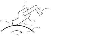
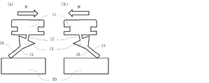
- FIG. 4 is a diagram showing a state in which the edge of the cleaning blade is in contact with the member to be cleaned; Schematic cross-sectional view of wiper member for vehicle The figure which shows the state in the cleaning process of the wiper member for vehicles.
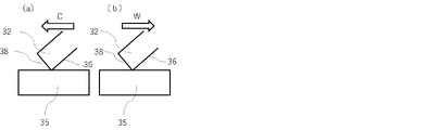
- Schematic diagram of cleaning wiper blade Explanatory drawing of the process in which the cleaning wiper blade cleans the member to be cleaned
- the inventors of the present invention have found that, for example, the elastic member and the cleaning member using the elastic member according to the embodiments described below have excellent followability to the member to be cleaned, and can be used in a high temperature environment or for a long period of time. It was found that deterioration of wiping performance can be prevented even when the temperature is raised.
- ⁇ Structure of cleaning member> ⁇ Peak temperature of loss factor (tan ⁇ )>
- the loss coefficient (hereinafter also referred to as "tan ⁇ ") of a sample sampled from the elastic member so as to include the contact portion with the member to be cleaned is measured at a temperature of -20 ° C to +60 ° C.
- the peak top temperature of the peak indicating the maximum value of tan ⁇ (hereinafter also referred to as “tan ⁇ peak temperature”) is 15.0° C. or less.
- the tan ⁇ peak temperature is an index generally called glass transition temperature. With the tan ⁇ peak temperature as a boundary, the elastic body becomes stronger as a resin on the low temperature side and behaves as an elastic body on the high temperature side. If the tan ⁇ peak temperature is 15.0° C. or less, the elastic member can function as an elastic body in the actual use temperature range (eg, 0 to 55° C.) of the cleaning member.
- the tan ⁇ peak temperature is preferably 14.0°C or lower, more preferably 13.0°C or lower. Although the lower limit is not particularly limited, it is preferably -5.0°C or higher, more preferably 0.0°C or higher, and still more preferably 5.0°C or higher.
- the tan ⁇ peak temperature can be adjusted by the ratio of hard segments and soft segments in the polyurethane. Specifically, the tan peak temperature can be controlled to be lowered by increasing the ratio of the soft segment to the hard segment. A specific method for achieving this is to increase the ratio of polyol to isocyanate in the polyurethane raw material composition.
- tan ⁇ Maximum value (peak value) of loss factor (tan ⁇ )> tan ⁇ represents the ratio of the viscous component to the elastic component in the elastic member. The smaller this value, the higher the ratio of the elastic component, and the faster the response to the force applied to the elastic member. Therefore, it is effective to reduce the maximum value of tan ⁇ (hereinafter also referred to as “tan ⁇ peak value”) in order to make the elastic member have good followability to the member to be cleaned. Specifically, by setting the tan ⁇ peak value of the elastic member to 0.20 or more and 0.55 or less, the elastic member can have good followability to the member to be cleaned.
- the tan ⁇ peak value is particularly preferably 0.25 or more and 0.50 or less.
- tan ⁇ ⁇ Loss factor (tan ⁇ ) at a temperature of 55°C>
- tan ⁇ represents loss energy with respect to stored energy.
- the ratio of converting input vibration energy into loss energy such as heat is high, so the elastic member can have high damping properties.
- the temperature of the elastic member may rise, for example, to about 55°C due to frictional heat.
- tan ⁇ becomes smaller, and while the ability to follow the member to be cleaned is improved, the damping ability is lowered.
- chattering occurs, abnormal noise is generated, and uneven wiping and unwiping may occur. Therefore, in order to exhibit stable wiping performance even when the temperature of the elastic member reaches 55°C, it is effective to set tan ⁇ at 55°C to 0.13 or more.
- the tan ⁇ at a temperature of 55°C is particularly preferably 0.15 or more.
- the upper limit is not particularly limited as long as it is less than the tan ⁇ peak value described above, but is preferably 0.50 or less, particularly 0.35 or less.
- the tan ⁇ peak value of the elastic member should be 0.55 or less, and the tan ⁇ at a temperature of 55°C should be 0.55 or less. A not too small polyurethane was found to be effective.
- difunctional diphenylmethane diisocyanate and trifunctional or higher polyfunctional isocyanate are used in a predetermined ratio, and the polyfunctional isocyanate is used in a high amount.
- the tan ⁇ peak temperature is 15.0 ° C. or less and the peak value is in the range of 0.20 to 0.55, while tan ⁇ at a temperature of 55 ° C. It has been found that a polyurethane having a value of 0.13 or more can be obtained. The reason why polyurethane having such physical properties can be obtained by using the materials described above is presumed as follows.
- each isocyanate group of a polyfunctional isocyanate can be reacted extremely efficiently with a polyol using a specific catalyst to form a polyurethane with a high crosslink density.
- This can increase the elastic term.
- the urethane bond derived from diphenylmethane diisocyanate has high planarity and is easily stacked.
- a portion with a developed crystal structure (hereinafter also referred to as “crystalline region”) is formed in the hard segment. In the crystalline region, when a force is applied from the outside, the crystal shifts and can absorb the external force, so it acts in the direction of increasing the viscosity term.
- Both the viscosity term and the elasticity term show large values in the normal temperature range, but the tan ⁇ peak value can be controlled within a predetermined range by adjusting the ratio of diphenylmethane diisocyanate and polyfunctional isocyanate.
- the value of the viscosity term decreases as the crystal structure loosens or unravels as the molecular motion becomes more active in the high temperature range.
- a three-dimensional crosslinked structure derived from polyfunctional isocyanate is developed, so the crystal structure collapses even at high temperatures. It is considered that the value of the viscosity term is maintained to some extent even at a high temperature such as 55°C.
- the elastic member according to one aspect of the present disclosure is a direct sample introduction type mass spectrometer that heats and vaporizes a sample sampled from the contact portion with the member to be cleaned in the ionization chamber and ionizes the molecules that make up the sample.
- M1 is the detected amount of all ions obtained when heating to 1000 ° C. at a temperature increase rate of 10 ° C./sec, and the range of m / z values derived from polyfunctional isocyanates having 3 or more isocyanate groups M2/M1 is 0.001 or more, where M2 is the integrated intensity of the peak of the extracted ion thermogram corresponding to .
- a polyurethane having M2/M1 of 0.001 or more can have a highly crosslinked structure resulting from tri- or more functional isocyanate.
- Polyurethane having such a highly crosslinked structure has a tan ⁇ peak temperature of 15.0° C. or less, a tan ⁇ peak value of 0.20 to 0.55, and a tan ⁇ at a temperature of 55° C. of 0.13.
- M2/M1 is preferably 0.002 or more, more preferably 0.004 or more.
- M2/M1 is preferably 0.035 or less, more preferably 0.020 or less. Therefore, M2/M1 is preferably 0.001 or more and 0.035 or less, particularly preferably 0.002 or more and 0.035 or less, and more preferably 0.004 or more and 0.020 or less.
- the integral of the extracted ion thermogram peak corresponding to the range of m/z values derived from diisocyanate obtained from the analysis method using the above-described direct sample introduction mass spectrometer When the strength is M3, M3/M1 on the first tapered surface and/or the second tapered surface is preferably 0.025 to 0.130, particularly 0.038 to 0.108 is more preferable.
- M3/M1 within the above range, the polyurethane may have a certain amount of crystal structure.
- a polyurethane having such a crystal structure has a tan ⁇ peak temperature of 15.0° C. or less, a tan ⁇ peak value of 0.20 to 0.55, and a tan ⁇ at a temperature of 55° C. of 0.13 or more. physical properties can be achieved more easily.
- M2/M3 is 0.046 or more and 0.441 or less.
- M2/M3 is a parameter representing the ratio of the structural portion derived from diisocyanate and the structural portion derived from tri- or higher polyfunctional isocyanate in the isocyanate-derived structure of the polyurethane.
- the polyurethane according to one aspect of the present disclosure is, for example, a reaction product of a polyurethane raw material composition containing an isocyanate compound containing a diisocyanate and a tri- or higher polyfunctional isocyanate, and an alcohol containing a tri- or higher polyfunctional alcohol. be able to.
- polyester polyols such as polyethylene adipate polyol, polybutylene adipate polyol, polyhexylene adipate polyol, (polyethylene/polypropylene) adipate polyol, (polyethylene/polybutylene) adipate polyol, (polyethylene/polyneopentylene) adipate polyol; caprolactone ring-opening polycaprolactone-based polyols obtained by polymerization; polyether polyols such as polyethylene glycol, polypropylene glycol and polytetramethylene glycol; and polycarbonate diols, which can be used alone or in combination of two or more. .
- polyester polyols using adipate are preferable because a polyurethane elastomer having excellent mechanical properties can be obtained.
- glycols having 4 or more carbon atoms such as polybutylene adipate polyol and polyhexylene adipate polyol. It is also preferable to use polyols having different numbers of carbon atoms in their glycols, such as polybutylene adipate polyol and polyhexylene adipate polyol.
- polyols having different numbers of carbon atoms in their glycols, such as polybutylene adipate polyol and polyhexylene adipate polyol.
- the presence of different types of polyols suppresses crystallization of the soft segments, thereby suppressing aggregation of the hard segments.
- glycols and polyhydric alcohols capable of extending the polyurethane elastomer chain can be used.
- glycols include the following. Ethylene glycol (EG), diethylene glycol (DEG), propylene glycol (PG), dipropylene glycol (DPG), 1,4-butanediol (1,4-BD), 1,6-hexanediol (1,6-HD ), 1,4-cyclohexanediol, 1,4-cyclohexanedimethanol, xylylene glycol (terephthalyl alcohol), triethylene glycol.
- Trimethylolpropane, glycerin, pentaerythritol, and sorbitol can be mentioned as trihydric or higher polyhydric alcohols. These can be used alone or in combination of two or more.
- diisocyanate examples include the following. 4,4'-diphenylmethane diisocyanate (4,4'-MDI), 2,4-tolylene diisocyanate (2,4-TDI), 2,6-tolylene diisocyanate (2,6-TDI), xylene diisocyanate (XDI) ), 1,5-naphthylene diisocyanate (1,5-NDI), p-phenylene diisocyanate (PPDI), hexamethylene diisocyanate (HDI), isophorone diisocyanate (IPDI), 4,4′-dicyclohexylmethane diisocyanate (hydrogenated MDI ), tetramethylxylene diisocyanate (TMXDI), carbodiimide-modified diphenylmethane diisocyanate.
- 4,4'-MDI 4,4'-diphenylmethane diisocyanate
- 2,4-TDI 2,4-to
- 4,4'-MDI in which two isocyanate groups have equivalent reactivity, is preferred.
- the polyfunctional isocyanate having three or more functional groups is selected from the group consisting of triphenylmethane-4,4',4''-triisocyanate (TTI), tris(phenylisocyanate) thiophosphate (TPTI) and polymeric MDI. at least one. Among them, tris(phenylisocyanate) thiophosphate (TPTI) and polymeric MDI can be used more preferably.
- the polymeric MDI is represented by the following chemical formulas (1) and (1)'.
- n in the chemical formula (1)' is preferably 1 or more and 4 or less.
- Chemical formula (1) is the case where n is 1 in chemical formula (1)'.
- the polyurethane is a polyurethane produced using polymeric MDI represented by the above chemical formula (1)' as a polyfunctional isocyanate having 3 or more functional groups
- m / z value range of 642.5 to 643.5 derived from n 3
- m / z value derived from n 4 in the range of 773.5 to 774.5
- the sum of integrated intensities may be M2.
- TTI as a trifunctional or higher isocyanate has a structure represented by the following chemical formula (3).
- the polyurethane synthesized using TTI has a peak derived from the cationized product of TTI, which appears in the m/z range of 366.5 to 367.5. should be M2.
- tris(phenylisocyanate) thiophosphate (TPTI) as a polyfunctional isocyanate with three or more functionalities has a structure represented by chemical formula (4).
- the polyurethane synthesized using TPTI is derived from the cationized product of TPTI, which appears in the m/z range of 464.5 to 465.5 in the extracted ion thermogram obtained by the mass spectrometry method described above.
- the integrated intensity of the peak may be M2.
- the polyurethane synthesized using 4,4'-MDI represented by the chemical formula (2) as a diisocyanate is derived from the structure represented by the chemical formula (2) in the extracted ion thermogram obtained by the mass spectrometry.
- the integrated intensity of the peak derived from 4,4'-MDI having a peak top at a position where the m/z value is 249.5 to 250.5 may be defined as M3.
- a generally used polyurethane elastomer curing catalyst can be used.
- tertiary amino alcohols are preferred.
- Examples of tertiary amino alcohols include 2-(dimethylamino)ethanol, 3-(dimethylamino)propanol, 2-(dimethylamino)-1-methylpropanol, 2- ⁇ 2-(dimethylamino)ethoxy ⁇ ethanol, 2 - ⁇ 2-(diethylamino)ethoxy ⁇ ethanol, 2-[ ⁇ 2-(dimethylamino)ethyl ⁇ methylamino]ethanol.
- 2-[ ⁇ 2-(dimethylamino)ethyl ⁇ methylamino]ethanol (trade name: TOYOCAT- RX5, manufactured by Tosoh Corporation) and 2- ⁇ 2-(dimethylamino)ethoxy ⁇ ethanol (trade name: TOYOCAT-RX3, manufactured by Tosoh Corporation) are preferable.
- Such a temperature-sensitive catalyst can react the polyfunctional isocyanate described above with a polyol with a very high efficiency, and can form a highly crosslinked structure in the polyurethane more effectively.
- Additives such as pigments, plasticizers, waterproofing agents, antioxidants, ultraviolet absorbers, light stabilizers, etc. can be added to the polyurethane raw material composition as needed.
- a cleaning member according to an aspect of the present disclosure can be used, for example, as a cleaning blade for an electrophotographic image forming apparatus.
- the member to be cleaned to which the electrophotographic cleaning blade is applied include an image bearing member such as a photoreceptor and an endless belt such as an intermediate transfer belt.
- an embodiment of the cleaning member will be described in detail using an image carrier as an example of the member to be cleaned, but the cleaning member is not limited to this.
- FIG. 1 is a schematic perspective view of the cleaning member 1.
- the cleaning member 1 comprises an elastic member 2 comprising polyurethane according to one aspect of the present disclosure, and a support member 3 supporting the elastic member 2 .
- the support member 3 preferably supports the elastic member 2 along the longitudinal direction of the elastic member 2 .
- FIG. 2 is an example schematically showing a cross-sectional state in which the cleaning member 1 is in contact with the member 6 to be cleaned.
- the elastic member 2 has a principal surface 4 facing the member to be cleaned 6 and a distal end surface 5 forming a distal edge together with the principal surface 4 .
- R indicates the rotation direction of the member to be cleaned.
- the temperature inside the electrophotographic image forming apparatus rises to nearly 55°C during operation. This is due not only to the heat generated at the contact portion between the cleaning member and the member to be cleaned, but also to the influence of the in-machine heater and the like. Further, the temperature of the elastic member is easily raised to about 55° C. by rubbing against a member to be cleaned such as an image bearing member.
- the cleaning blade provided with the elastic member according to the present disclosure stable cleaning performance can be maintained even when the elastic member reaches a high temperature such as 55°C.
- the electrophotographic cleaning blade according to one aspect of the present disclosure contributes to stable formation of high-quality electrophotographic images.
- the supporting member is a member 3 that supports the end of the elastic member 2 in the electrophotographic image forming apparatus so that it contacts the surface of the electrophotographic photosensitive drum 6 as a member to be cleaned.
- the configuration of the support member is not particularly limited as long as it exhibits such a function.
- the material is not particularly limited as long as it exhibits the function, and examples thereof include the following materials. Metal materials such as steel plates, stainless steel plates, galvanized steel plates, and chromium-free steel plates, and resins such as 6-nylon and 6,6-nylon.
- a method for manufacturing the cleaning blade according to the present disclosure is not particularly limited, and a suitable method may be selected from known methods. For example, after applying a mold release agent to the inner surface of the cleaning blade mold and arranging the support member, the polyurethane raw material composition is injected and heated to cure, thereby forming a plate-like elastic member (blade member). It is possible to obtain a cleaning blade in which the support member and the support member are integrated.
- the polyurethane preferably contains a reactant of a composition containing an isocyanate compound containing a diisocyanate and a polyfunctional isocyanate having a functionality of 3 or more and an alcohol containing a polyfunctional alcohol having a functionality of 3 or more.
- a method for producing an elastic member includes a step of reacting an isocyanate compound and a polyol to obtain a prepolymer, and a polyol and an alcohol containing a trifunctional or higher polyfunctional alcohol as a curing agent and a catalyst. , a step of obtaining a polyurethane raw material composition, and a step of curing the obtained polyurethane raw material composition to obtain an elastic member.
- the NCO content is preferably about 5 to 30% by mass, more preferably about 8 to 15% by mass.
- the reaction temperature is preferably about 50 to 120°C, more preferably about 70 to 90°C.
- the reaction time is preferably about 30 minutes to 400 minutes, more preferably about 120 minutes to 300 minutes.
- the content of each material in the polyurethane raw material composition is not particularly limited as long as it satisfies the above tan ⁇ and M2/M1.
- the content of diisocyanate in the polyurethane raw material composition is preferably 2 to 30% by mass, more preferably 10 to 25% by mass.
- the content of tri- or higher polyfunctional isocyanate in the polyurethane raw material composition is preferably 5 to 35% by mass, more preferably 10 to 20% by mass.
- the polyol content in the polyurethane raw material composition is preferably 30 to 80% by mass, more preferably 50 to 70% by mass.
- the content of trifunctional or higher polyfunctional alcohol in the polyurethane raw material composition is preferably 1 to 10% by mass, more preferably 2 to 5% by mass.
- silicone release agent known release agents such as fluorine-based release agents, silicone-based release agents, and surfactants can be used.
- a template is preferred.
- silicone release agent for example, a mixture of silicone oil and silicone resin diluted with a solvent is used.
- silicone oil for example, dimethyl silicone oil (ELEMENT 14 PDMS series (trade name, manufactured by Momentive Performance Materials)
- silicone resin for example, "SR1000”, “SS4230”, “SS4267” (all trade names, manufactured by Momentive Performance Materials), and "MQ803TF” (trade name, manufactured by Asahi Kasei Wacker Silicone Co., Ltd.) are used. be able to. Any grade of silicone oil and silicone resin described above can be used in combination with silicone oil.
- the ratio of nonvolatile matter in the silicone resin is preferably 10 to 70% by mass.
- a cleaning blade forming mold consisting of an upper mold and a lower mold is prepared, an adhesive is applied to one end of the support member, and this part is placed in a state of protruding into the cavity for forming the blade part of the mold. do.
- a liquid polyurethane raw material composition which is a raw material for the elastic member, was injected into this mold from the opening in the end face in the transverse direction, and cured at 100° C. to 150° C. to integrate the support member and the elastic member. Obtain a molded product.
- a cleaning blade can be manufactured by cutting the elastic member into a predetermined shape (hereinafter referred to as manufacturing method I).
- a mold for the cleaning blade consisting of an upper mold and a lower mold is prepared, an adhesive is applied to one end of the support member, and this part is protruded into the cavity for forming the blade part of the mold. Place the books face to face.
- a liquid polyurethane raw material composition which is the raw material for the elastic member, is injected into this mold through the openings on the longitudinal end faces, and cured at 100° C. to 150° C. to integrate the two support members with the elastic member. to obtain a molded product.
- the mold is tilted by 0 to 25° so that the raw material composition flows first through one of the two support members.
- a cleaning blade can be manufactured (hereinafter referred to as manufacturing method II)
- a polyurethane elastomer sheet is separately formed from the above polyurethane raw material composition, cut into strips to prepare an elastic member, and the adhered portion of the elastic member is superimposed on a support member to which an adhesive has been applied or adhered.
- a method of bonding by heating and pressurizing can also be taken.
- the cleaning blade can be used by being incorporated in a process cartridge that is detachably attached to the electrophotographic image forming apparatus.
- a process cartridge including an image carrier as a member to be cleaned and a cleaning blade disposed so as to be able to clean the surface of the image carrier
- the cleaning blade according to the present embodiment is used as the cleaning blade.
- a blade can be used.
- Such a process cartridge contributes to stable formation of high quality electrophotography.
- an electrophotographic image forming apparatus includes an image carrier such as a photoreceptor, and a cleaning blade arranged so as to be able to clean the surface of the image carrier, and the cleaning blade has the above-described cleaning blade.
- a cleaning blade Such an electrophotographic image forming apparatus can stably form high-quality electrophotographic images.
- a cleaning member according to the present disclosure can be used as a vehicle wiper blade for wiping the surface of a member to be cleaned. That is, the cleaning member is preferably a vehicle wiper member for a wiper device on a member to be cleaned such as a vehicle windshield.
- BACKGROUND ART Wiper blades for vehicles are used for wiping off water droplets, dirt, etc. adhering to glass surfaces such as windshields and rear windshields of automobiles, trains, ships, aircrafts, etc., to ensure the visibility of the operator.
- the cleaning member used for the vehicle wiper blade has a portion with a large curvature and a portion with a small curvature for cleaning various objects such as liquid deposits, fine particles contained in exhaust gas, and dust such as asphalt. Sufficient followability is required for wiping from the glass surface. In addition, when wiping a highly adhesive object to be cleaned from a glass surface, it is required to suppress chattering caused by the temperature rise of the cleaning member due to use in a hot environment and prolonged use.
- the vehicle wiper member includes a vehicle wiper support portion 11 and a lip portion (tip portion) 13, as shown in FIG. 3(a).
- a neck 12 may be interposed between the support portion 11 and the lip portion 13 to make the lip portion 13 swingable.
- the neck 12 may be narrower than the vehicle wiper supporting portion 11 and the lip portion 13 in the cross section in the direction orthogonal to the longitudinal direction of the vehicle wiper member.
- the lip portion 13 of the wiper member for a vehicle is tilted in the wiping direction so that a portion of the lip portion abuts against the surface of the member to be cleaned.
- the neck 12 is provided as shown in FIG. 4B
- the lip portion 13 is tilted in the wiping direction with the neck as the starting point, and a portion of the lip portion is brought into contact with the surface of the member to be cleaned.
- a shoulder portion 20 may be provided on the side closer to the windshield wiper support portion 11 .
- the shoulder portion may have a tapered shape 14 in which the width gradually decreases in the direction away from the support portion 11 from the side closer to the support portion 11 . Since the shoulder portion is provided, the lip portion is inclined during wiping, and the vehicle wiper support portion and the shoulder portion come into contact with each other. As a result, the inclination during wiping and the angle of the lip portion with respect to the member to be cleaned can be stably controlled.
- FIGS. 4(a) and 4(b) are explanatory diagrams showing a state in the cleaning process of the vehicle wiper member.
- the lip portion 13 of the wiper member for a vehicle includes a first lip surface 15 in contact with the member to be cleaned 50 and a second lip surface 16 opposite to the first lip surface 15; a tip surface 17 forming a first edge 18 and a second edge 19 on the side of the lip portion 13 farthest from the support portion 11 together with the first lip surface 15 and the second lip surface 16; , (see FIG. 3 for first edge 18, second edge 19 and tip surface 17).
- the lip portion 13 of the wiper member for a vehicle includes a second lip surface 16, a first lip surface 15 opposite to the second lip surface 16, and the first lip surface 15. and a tip surface 17 forming a first edge 18 and a second edge 19 on the side of the lip portion 13 farthest from the support portion 11 together with the second lip surface 16 (first See FIG. 3 for edge 18, second edge 19 and tip face 17).
- the arrow R indicates the cleaning direction of the vehicle wiper member. By switching from cleaning in the direction of arrow R in FIG. 4A to cleaning in the direction of arrow R in FIG. is switched to the lip surface 16 of .
- a wiper blade for a vehicle is measured by the above-described method using a loss factor tan ⁇ measurement sample manufactured so as to include the contact portion with the member to be cleaned from the elastic member in the lip portion, which is the contact portion with the member to be cleaned.
- the peak temperature of the peak indicating the maximum value of tan ⁇ and the maximum value of the peak satisfy the above relationship.
- the vehicle wiper member has at least the vehicle wiper support portion and the lip portion that contacts the surface of the windshield, the uniformity of contact in the longitudinal direction is improved, and sufficient damping properties are exhibited. This is preferable because it suppresses chattering.
- the vehicle wiper member has at least a lip portion that contacts the vehicle wiper support portion and the surface of the windshield, and a shoulder portion on the vehicle wiper support portion side of the lip portion, uniformity of contact over the longitudinal direction can be achieved. is further improved, and sufficient vibration damping properties are exhibited, thereby suppressing chattering.
- the vehicle wiper member comprises at least a vehicle wiper support portion and a lip portion swingably connected to the vehicle wiper support portion via a neck
- the uniformity of contact over the length is improved. It is preferable because it suppresses chattering by improving and exhibiting sufficient damping properties.
- the wiper blade for vehicles satisfies the above conditions for the loss factor tan ⁇ using an elastic member as a sample at the lip portion which is the contact portion with the member to be cleaned.
- chattering can be suppressed by exhibiting sufficient vibration damping properties.
- the method for manufacturing the vehicle wiper blade is not particularly limited, and can be selected from known methods.
- a lip portion having a tapered portion can be obtained by injecting a polyurethane elastomer raw material composition into a mold for vehicle wiper blades and heating and curing the composition.
- the tip of the tapered portion may be cut to form a shape. This is preferable because it is possible to form the first edge and the second edge with high smoothness.
- a vehicle wiper blade may be manufactured by manufacturing a pair of tandem-shaped moldings formed in contact with each other so that the tapered portions face each other and cutting them in the longitudinal direction.
- the blade supporting portion and the neck may be manufactured using conventionally known materials and manufacturing methods.
- the vehicle wiper blades of the present disclosure can be used in various types of wiper systems, such as tandem and opposed wiping.
- the wiping cleaning member cleans the surface of the member to be cleaned by bringing the elastic member into contact with the surface of the member to be cleaned. It can be used as a cleaning wiper blade for cleaning surfaces such as windows, tiles, walls, lenses and solar panels.
- a cleaning wiper blade is required to have sufficient followability to suppress uneven wiping without strongly pressing the surface to be cleaned.
- wiping an object to be cleaned that has a strong adhesive force from a surface to be cleaned, it is required to suppress chattering due to the temperature rise of the cleaning member due to increased pressure.
- the cleaning wiper blade has an elastic member 32 that is pressed against the surface to be cleaned. Clean the surface of the cleaning member.
- FIG. 5(a) is provided with only the elastic member 32, but as shown in FIG. 5(c) (for stably pressing in the longitudinal direction of the cleaning wiper blade), elastic members are provided along the longitudinal direction of the elastic member. It is preferable to provide an elastic member supporting portion 33 for supporting the member.
- a grip portion 31 to be gripped and an elastic member 32 supported by the grip portion 31 and pressed against the surface to be cleaned may be provided.
- an elastic member supporting portion 33 that supports the elastic member 32 may be provided between the grip portion 31 and the elastic member 32.
- the grip part 31 is a part that can be gripped or held by a main body of cleaning work represented by a hand.
- the grip portion 31 extends in a direction intersecting the direction in which the elastic member 32 extends.
- the shape of the grip portion 31 is not particularly limited as long as it can be gripped or held by the subject of cleaning work.
- a jig for assisting cleaning may be connected to the grip portion.
- it may be a jig for extending the grip for cleaning high places.
- the material of the grip portion 31 is not particularly limited, and may be made of resin or metal.
- FIG. 5(d) it may have a support grip portion 34 in which the elastic member support portion and the grip portion are integrated.
- the support grip portion 34 may have a shape that sandwiches a portion of the elastic member 32 .
- the elastic member 32 and the grip portion 31 may be integrated.
- the grip portion 31, the elastic member support portion 33, and the elastic member 32 may be detachable or integrated.
- the cleaning wiper blade has tan ⁇ measured by the above-described method using a sample for loss factor tan ⁇ measurement that is manufactured so as to include the contact portion with the member to be cleaned from the elastic member 32 in the contact area with the member to be cleaned.
- the peak temperature of the peak showing the maximum value of and the maximum value of the peak satisfy the above relationship.
- the cleaning wiper blade is provided with the elastic member supporting portion 33, it is preferable because the followability is further improved by stably pressing the cleaning wiper blade in the longitudinal direction. Furthermore, it is preferable that the cleaning wiper blade is provided with a grip portion 31 to be gripped, because the followability is further improved by stably pressing the cleaning wiper blade in the longitudinal direction.
- a method for manufacturing the elastic member of the cleaning wiper blade is not particularly limited, and can be selected from known methods.
- the elastic member of the cleaning wiper blade can be obtained by injecting a polyurethane elastomer raw material composition into a mold for the elastic portion of the cleaning wiper blade and heating and curing it.
- the tip of the elastic portion may be cut to form a shape. This is preferable because it is possible to form the edge on the tip side with a high degree of smoothness.
- a cleaning wiper blade may be manufactured by manufacturing a pair of tandem-shaped molded bodies in which the tip surfaces of the elastic portions are in contact with each other and cut in the longitudinal direction.
- FIG. 6 is an explanatory view showing the state of the cleaning process in which the cleaning wiper blade contacts and slides on the member 35 to be cleaned during cleaning.
- the direction in which the cleaning wiper blade is moved is a direction that intersects with the direction in which the elastic member 32 extends, and it can be moved and used in the pushing direction C shown in FIG. 6(a) and the pulling direction W shown in FIG. 6(b).
- the tip side edge formed by the lip surface 36 and the tip surface 38 may be brought into contact with the member 35 to be cleaned and moved.
- the dirt may be pre-wet with a liquid cleaning agent, water, or the like, and removed together with the liquid cleaning agent, water, or the like.
- the shape and mounting method of each of the elastic member 32, the elastic member support portion 33 and the grip portion 31 or the support grip portion 34 are not limited. Also, the method of attaching the elastic member support portion 33 to the elastic member 32 and the method of attaching the grip portion 31 or the support grip portion 34 to the elastic member support portion 33 are not limited.
- Example 1 [Support member] A galvanized steel sheet having a thickness of 1.6 mm was prepared and processed to obtain a support member having an L-shaped cross section, indicated by reference numeral 3 in FIG. A urethane-metal one-layer adhesive (trade name: Chemlock 219, manufactured by Road Corporation) was applied to the portion of the support member that the elastic member was in contact with.
- a curing agent was prepared by mixing the materials shown in Table 2 below.
- the curing agent was added to the prepolymer described above and mixed to obtain a raw material composition.
- the portion of the support member to which the adhesive was applied was arranged so as to protrude into the cavity of the cleaning blade molding die (manufacturing method I). Then, the raw material composition was injected into the cavity and cured at a temperature of 130° C. for 2 minutes. After that, the mold was removed to obtain an integrally molded body of the polyurethane and the supporting member.
- Release Agent A is a mixture of materials listed in Table 3 below.
- the obtained integrally molded polyurethane was cut so that the edge angle was 90 degrees and the distances in the lateral direction, thickness direction and longitudinal direction of the polyurethane were 7.5 mm, 1.8 mm and 240 mm, respectively.
- a cleaning blade according to the example was obtained. Then, this cleaning blade was subjected to the following evaluations.
- Apparatus dynamic viscoelasticity measuring apparatus (trade name: DMA EXPLEXOR 500N, manufactured by NETZSCH; static strain: 2%; Dynamic strain: 0.5%; Measurement temperature: -20°C to 60°C; Measurement frequency: 10 Hz.
- a sample for loss factor tan ⁇ measurement was prepared as follows. A sample was prepared so as to include the corner of the contact portion of the elastic member with the member to be cleaned. It was prepared by cutting into rectangular parallelepipeds of 0.5 mm, 1.0 mm and 30 mm.
- the detected amount M1 of all ions is the sum of the integrated intensities of all peaks in the total ion current thermogram obtained, and the extracted ion thermogram corresponding to the range of m / z values derived from trifunctional or higher polyfunctional isocyanates.
- M2 the sum of integrated intensities of gram peaks was defined as M2, (M2/M1) was calculated using the values of M1 and M2.
- the polyurethane according to this example was synthesized using polymeric MDI (MR200) as a trifunctional or higher isocyanate.
- MR200 polymeric MDI
- m / z value indicating n 3 in the range of 642.5 to 643.5
- m / z value indicating n 4
- a peak derived from the cationized product of polymeric MDI was detected, having peak tops at each position of 773.5 to 774.5. Therefore, in this example, the sum of the integrated intensities of the respective peaks was defined as M2.
- TTI used as a tri- or higher functional isocyanate has a structure represented by the following chemical formula (3).
- Polyurethane synthesized using TTI is a cationized product of TTI having a peak top at m/z 366.5 to 367.5 in the extracted ion thermogram obtained by the above method. Derived peaks were detected. Therefore, in this example, the integrated intensity of the peak was defined as M2.
- tris(phenylisocyanate)thiophosphate used as a polyfunctional isocyanate having a functionality of 3 or more in the examples described later has a structure represented by the chemical formula (4).
- the polyurethane synthesized using TPTI is a cationized product of TPTI that has a peak top at m/z of 464.5 to 465.5 in the extracted ion thermogram obtained by the above method. Derived peaks were detected. Therefore, in this example, the integrated intensity of the peak was defined as M2.
- Example 1 The cleaning blade of Example 1 was incorporated into a cyan cartridge of a color laser beam printer (trade name: HP LaserJet Enterprise Color M553dn, manufactured by HP) as a cleaning blade for a photosensitive drum, which is a member to be cleaned. Further, the toner in the developing machine of the cyan cartridge was entirely replaced with toner 1 described later.
- a color laser beam printer (trade name: HP LaserJet Enterprise Color M553dn, manufactured by HP) as a cleaning blade for a photosensitive drum, which is a member to be cleaned.
- toner in the developing machine of the cyan cartridge was entirely replaced with toner 1 described later.
- B Image defects (streaks on the image) due to the cleaning blade did not occur in the normal evaluation, but occurred very slightly in the double evaluation (streak length of 5 mm or less).
- C Image defects (streaks on images) caused by the cleaning blade do not occur in normal evaluation, but occur in double evaluation (exceeding 10 mm). Or it occurs in normal evaluation.
- Example 1 The cleaning blade of Example 1 was incorporated into a cyan cartridge of a color laser beam printer (trade name: HP LaserJet Enterprise Color M553dn, manufactured by Hewlett-Packard) as a cleaning blade for a photosensitive drum, which is a member to be cleaned. Further, the toner in the developing machine of the cyan cartridge was entirely replaced with toner 1 described later.
- a color laser beam printer (trade name: HP LaserJet Enterprise Color M553dn, manufactured by Hewlett-Packard) as a cleaning blade for a photosensitive drum, which is a member to be cleaned.
- toner in the developing machine of the cyan cartridge was entirely replaced with toner 1 described later.
- the waste toner was evaluated while making a hole in the rear surface of the cartridge and sucking it out.
- the resulting images were ranked for performance according to the following evaluation criteria.
- C Image defects (streaks on images) caused by the cleaning blade do not occur in normal evaluation, but occur in double evaluation (exceeding 10 mm). Or it occurs in normal evaluation. Or an abnormal noise occurs.
- a calcium chloride aqueous solution obtained by dissolving 9.2 parts of calcium chloride (dihydrate) in 10.0 parts of ion-exchanged water is mixed together. to prepare an aqueous medium containing a dispersion stabilizer. Furthermore, 10% by mass hydrochloric acid was added to the aqueous medium to adjust the pH to 5.0, and an aqueous medium 1 was obtained.
- a homomixer manufactured by Tokushu Kika Kogyo Co., Ltd. was used to uniformly dissolve and disperse at 500 rpm to prepare a polymerizable monomer composition.
- the temperature of the aqueous medium 1 is set at 70°C, T.E. K. While maintaining the rotation speed of the homomixer at 15000 rpm, the polymerizable monomer composition was charged into the aqueous medium 1, and 10.0 parts of t-butyl peroxypivalate as a polymerization initiator was added. The mixture was granulated for 10 minutes while maintaining 15000 rpm with the stirring device.
- the temperature of the resulting toner base particle dispersion was cooled to 55° C.
- 25.0 parts of a hydrolyzate of an organosilicon compound was added to initiate polymerization of the organosilicon compound.
- the pH was adjusted to 5.5 with a 3.0% by mass sodium hydrogen carbonate aqueous solution.
- the mixture was maintained at 55° C. for 60 minutes while stirring, and then adjusted to pH 9.5 using a 3.0% by mass sodium hydrogencarbonate aqueous solution, and further maintained for 240 minutes to obtain a toner particle dispersion.
- the toner particle dispersion After completion of the polymerization process, the toner particle dispersion is cooled, and hydrochloric acid is added to the toner particle dispersion to adjust the pH to 1.5 or less, and the mixture is left with stirring for 1 hour, followed by solid-liquid separation using a pressurized filter to form a toner cake. got This was reslurried with ion-exchanged water to form a dispersion liquid again, and then solid-liquid separation was performed using the aforementioned filter to obtain a toner cake. The resulting toner cake was dried and classified in a constant temperature bath at 40° C. for 72 hours to obtain Toner 1 .
- Example 2 The same procedure as in Example 1 was repeated except that 1.32 g of RX3 (trade name TOYOCAT-RX3, manufactured by Tosoh Corporation) was used as a catalyst and RX5 was not used.
- RX3 trade name TOYOCAT-RX3, manufactured by Tosoh Corporation
- Example 3 As a curing agent, 43.1 g of TMP, 244.3 g of PHA1000, 0.13 g of Polycat 46, and 1.01 g of RX5 were mixed to prepare a curing agent. The mold used was coated with a release agent B before the polyurethane elastomer composition was injected.
- Release agent B includes ELEMENT 14 PDMS 1000-JC 3.04 g (trade name, manufactured by Momentive Performance Materials), ELEMENT 14 PDMS 10K-JC 3.71 g (trade name, manufactured by Momentive Performance Materials), A mixture of 8.25 g of SR1000 (trade name, manufactured by Momentive Performance Materials) and 85 g of EXXSOL DSP145/160 was used.
- the blade was manufactured using Manufacturing Method II.
- the inclination angle of the mold was 0°.
- the polyurethane elastomer composition was poured into a cleaning blade molding die, cured at 130° C. for 2 minutes, and removed from the mold to obtain an integrally molded body of polyurethane and a support member. Otherwise, the cleaning blade of Example 2 was obtained in the same manner as in Example 1. Physical properties were measured and evaluated in the same manner as in Example 1.
- Example 15 ⁇ Preparation of raw material for vehicle wiper blade> It was carried out in the same manner as in Example 1.
- a wiper blade was obtained by appropriately cutting the tip side of the lip portion of this polyurethane. The distances in the thickness direction and longitudinal direction of the tip of the lip portion were set to 0.6 mm and 450 mm, respectively. The distance in the thickness direction and width direction of the neck portion was set to 0.7 mm and 0.5 mm, and the distance in the thickness direction of the shoulder portion was set to 3.0 mm.
- the obtained wiper blades were evaluated by the following methods.
- silicone oil film removal area ratio %
- Example 16-19, 22-23 A wiper blade for a vehicle was produced and evaluated in the same manner as in Example 15 except that the curing agent material and its compounding amount were as described in Table 6.
- Example 20 A vehicle wiper blade having a blade support portion, a lip portion, and a neck portion was manufactured and evaluated in the same manner as in Example 15, except that a cavity-shaped molding die having a shape having a shoulder portion was used. .
- Example 21 A vehicle wiper blade having a blade support portion and a lip portion was manufactured and evaluated in the same manner as in Example 15, except that a cavity-shaped molding die having a neck portion and a shoulder portion was used.
- Examples 24 to 30 Vehicle wiper blade in the same manner as in Example 15 except that the types and amounts of various materials for the prepolymer and/or the types and amounts of various materials for the curing agent are shown in Table 7. was produced and evaluated.
- Example 31 ⁇ Preparation of raw material for cleaning wiper blade> It was carried out in the same manner as in Example 1.
- the mold used was coated with release agent A in the same manner as in Example 1 before the polyurethane elastomer composition was injected.
- the tip side of the obtained polyurethane molding was appropriately cut to prepare a tip face, and an elastic portion of a cleaning wiper blade was obtained.
- the distances in the thickness direction, width direction, and length direction of the cleaning wiper blade elastic portion were set to 1.8 mm, 20 mm, and 300 mm, respectively.
- the obtained cleaning wiper blades were evaluated by the following methods.
- FIG. 7 shows a schematic diagram of the test machine used for the evaluation.
- the elastic member 113 of the wiper blade was attached as shown in FIG. manufactured by Kogyosha).
- the test apparatus was left in a low temperature, low humidity environment (temperature of 15° C., relative humidity of 10%) for 24 hours, and then cleaned under the following conditions.
- the elastic member 113 of the cleaning wiper blade is brought into contact with the glass plate 114, and the glass plate 114 is pulled by an electric ROBO Cylinder (trade name: RCP4-SA5C, manufactured by IAI Co., Ltd.) 115 to keep the temperature constant.
- ROBO Cylinder trade name: RCP4-SA5C, manufactured by IAI Co., Ltd.
- Fig. 6 shows an enlarged view of the portion where the elastic member of the cleaning wiper blade and the glass surface are in contact.
- the elastic member 32 of the cleaning wiper blade was adjusted to be in contact with the glass surface 35 at an angle of 45 degrees.
- the elastic member 32 of the cleaning wiper blade was attached so as to face the direction of W and the direction of C indicated by arrows in FIG.
- silicone oil film removal area ratio The ratio of the area where the silicone oil film was removed to the area of the surface wiped by the cleaning wiper blade (hereinafter referred to as silicone oil film removal area ratio (%)) was calculated.
- follow-up performance was evaluated according to the following criteria from the calculated silicone oil film removal area ratio. The evaluation results are shown in Table 8 as followability of the cleaning wiper blade.
- Examples 32 to 44 Cleaning was carried out in the same manner as in Example 31 except that the types and amounts of various materials for the prepolymer and/or the types and amounts of the various materials for the curing agent were as shown in Tables 8 and 9. A wiper blade for use was produced and evaluated.
- a cleaning wiper blade was prepared in the same manner as in Example 31 except that the types and amounts of various materials for the prepolymer and/or the types and amounts of the various materials for the curing agent were as shown in Table 9. was produced and evaluated.
- a cleaning member comprising an elastic member containing polyurethane, and cleaning the surface of the member to be cleaned by bringing at least part of the elastic member into contact with the surface of the member to be cleaned,
- the loss factor tan ⁇ of a sample sampled from the elastic member so as to include the portion in contact with the member to be cleaned was measured in the temperature range of -20°C to +60°C,
- the peak temperature of the peak indicating the maximum value of tan ⁇ is present at 15.0° C.
- tan ⁇ is 0.20 or more and 0.55 or less
- tan ⁇ at a temperature of 55°C is 0.13 or more
- a sample sampled from the elastic member so as to include a portion in contact with the member to be cleaned is heated and vaporized in an ionization chamber, and a direct sample introduction mass spectrometer is used to ionize the molecules that make up the sample. The detected amount of all ions obtained when heating to 1000 ° C.
- a cleaning member wherein M2/M1 is 0.001 or more.
- Configuration 2 The cleaning member according to configuration 1, wherein M2/M1 is 0.001 or more and 0.035 or less.
- Composition 3 The polyurethane is An isocyanate compound containing a diisocyanate and a polyfunctional isocyanate having 3 or more isocyanate groups, and 3.
- the cleaning member according to configuration 1 or 2 comprising a reactant of an alcohol-containing composition containing a tri- or higher functional alcohol.
- composition 4 The diisocyanate obtained when the sample is heated and vaporized in an ionization chamber and heated to 1000°C at a temperature increase rate of 10°C/sec using a direct sample introduction mass spectrometer that ionizes the molecules that make up the sample.
- composition 5 Structures 1 to 4, wherein the polyfunctional isocyanate is at least one selected from the group consisting of polymeric MDI, triphenylmethane-4,4',4''-triisocyanate, and tris(phenylisocyanate) thiophosphate.
- the polyfunctional isocyanate is at least one selected from the group consisting of polymeric MDI, triphenylmethane-4,4',4''-triisocyanate, and tris(phenylisocyanate) thiophosphate.
- the diisocyanate is 4,4'-diphenylmethane diisocyanate, 2,4-tolylene diisocyanate, 2,6-tolylene diisocyanate, xylene diisocyanate, 1,5-naphthylene diisocyanate, p-phenylene diisocyanate, hexamethylene diisocyanate, and isophorone diisocyanate. , 4,4′-dicyclohexylmethane diisocyanate, tetramethylxylene diisocyanate, and carbodiimide-modified diphenylmethane diisocyanate. (Composition 7) 7.
- Composition 8 The cleaning member of configuration 7, further comprising a support member supporting said resilient member.
- Composition 9) 7.
- Configuration 10) 10.
- Configuration 9 or 10 wherein the vehicle wiper member includes at least a vehicle wiper support portion and a lip portion that contacts a surface of the windshield, and a shoulder portion on the vehicle wiper support portion side of the lip portion.
- composition 12 Configurations 9 to 9, wherein the vehicle wiper member includes at least a vehicle wiper support portion and a lip portion swingably connected to the vehicle wiper support portion via a neck. 12. A cleaning member according to any one of 11.
- Composition 13 The cleaning member according to any one of configurations 1 to 6, wherein the cleaning member is a wiping cleaning member that cleans the surface of the member to be cleaned by bringing the elastic member into contact with the surface of the member to be cleaned.
- Composition 14 14. The cleaning member according to configuration 13, wherein the cleaning member has the elastic member that contacts the surface of the member to be cleaned, and an elastic member supporting portion that supports the elastic member along the longitudinal direction of the elastic member.
- composition 15 An elastic member containing polyurethane, When the loss factor tan ⁇ of a sample sampled from the elastic member was measured in the temperature range of -20°C to +60°C, The peak temperature of the peak indicating the maximum value of tan ⁇ is present at 15.0° C. or less, and the maximum value of tan ⁇ is 0.20 or more and 0.55 or less, tan ⁇ at a temperature of 55°C is 0.13 or more, and When a sample sampled from the elastic member is heated and vaporized in an ionization chamber, and heated to 1000° C. at a temperature elevation rate of 10° C./sec using a direct sample introduction mass spectrometer that ionizes the molecules that make up the sample.
- the detected amount of all ions obtained in is M1, and the integrated intensity of the peak of the extracted ion thermogram corresponding to the m / z value range derived from the polyfunctional isocyanate having 3 or more isocyanate groups is M2.
- An elastic member, wherein M2/M1 is 0.001 or more. Composition 16
- the polyurethane is An isocyanate compound containing a diisocyanate and a polyfunctional isocyanate having 3 or more isocyanate groups, and 17.
- the elastic member according to configuration 15 or 16 comprising a reactant of an alcohol-containing composition containing a tri- or higher polyfunctional alcohol.
- composition 18 The diisocyanate obtained when the sample is heated and vaporized in an ionization chamber and heated to 1000°C at a temperature increase rate of 10°C/sec using a direct sample introduction mass spectrometer that ionizes the molecules that make up the sample. Any one of configurations 15 to 17, wherein M3/M1 is 0.025 to 0.130, where M3 is the integrated intensity of the peak of the extracted ion thermogram corresponding to the range of m / z values derived from An elastic member as described.
Landscapes
- Chemical & Material Sciences (AREA)
- Physics & Mathematics (AREA)
- General Physics & Mathematics (AREA)
- Health & Medical Sciences (AREA)
- Chemical Kinetics & Catalysis (AREA)
- Medicinal Chemistry (AREA)
- Polymers & Plastics (AREA)
- Organic Chemistry (AREA)
- Engineering & Computer Science (AREA)
- Plasma & Fusion (AREA)
- Mechanical Engineering (AREA)
- Polyurethanes Or Polyureas (AREA)
Abstract
Description
該弾性部材から、該被清掃部材と当接する部分を含むようにサンプリングした試料をイオン化室内で加熱気化させ、該試料を構成する分子をイオン化する直接試料導入方式の質量分析計を用いて、昇温速度10℃/秒で1000℃まで加熱したときに得られる全てのイオンの検出量をM1とし、イソシアネート基を3個以上有する多官能イソシアネートに由来するm/z値の範囲に対応する抽出イオンサーモグラムのピークの積分強度をM2としたとき、M2/M1が0.001以上である清掃部材が提供される。
<清掃部材の構成>
<損失係数(tanδ)のピーク温度>
弾性部材を備えた清掃部材において、該弾性部材から、被清掃部材との当接部を含むようにサンプリングした試料の損失係数(以降、「tanδ」ともいう)を温度-20℃~+60℃の範囲で測定したとき、tanδの最大値を示すピークのピークトップ温度(以降、「tanδピーク温度」ともいう)が、15.0℃以下である。tanδピーク温度は一般的にガラス転移温度と呼ばれる指標である。弾性体はtanδピーク温度を境に、低温側では樹脂としての性質が強くなり、高温側では弾性体として振る舞う。tanδピーク温度が15.0℃以下であれば、清掃部材の実使用温度領域(例えば、0~55℃)において、弾性部材を弾性体として機能させることができる。
tanδは、弾性部材における弾性成分に対する粘性成分の割合を表している。この値が小さいほど弾性成分の割合が大きいことを表し、弾性部材に加わった力に対する応答が早い。そのため、被清掃部材に対する良好な追従性を有する弾性部材とするためには、tanδの最大値(以降、「tanδピーク値」ともいう)を低くすることが有効である。
具体的には、弾性部材のtanδピーク値を0.20以上0.55以下とすることで、当該弾性部材は被清掃部材に対する良好な追従性を有し得る。tanδピーク値は、特には、0.25以上0.50以下であることが好ましい。
tanδをエネルギーの側面から見ると、貯蔵エネルギーに対する損失エネルギーを表す。tanδが高いと、入力された振動エネルギーを熱などの損失エネルギーに変換する割合が高いため、弾性部材は高い制振性を有し得る。
このような結晶構造を備えたポリウレタンは、tanδピーク温度が15.0℃以下であり、tanδピーク値が0.20~0.55であり、かつ、温度55℃におけるtanδが0.13以上といった物性をより容易に達成し得る。

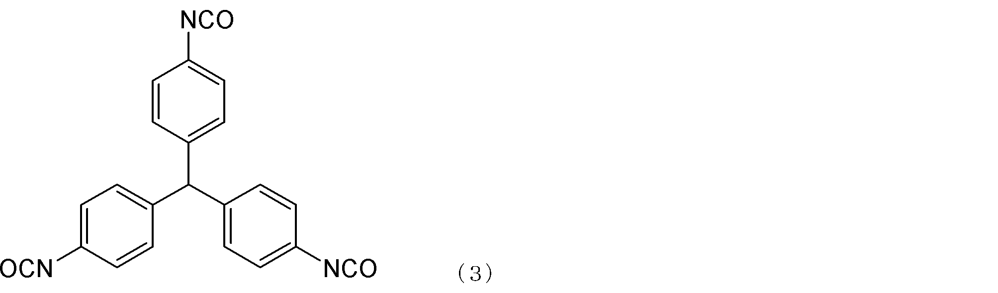
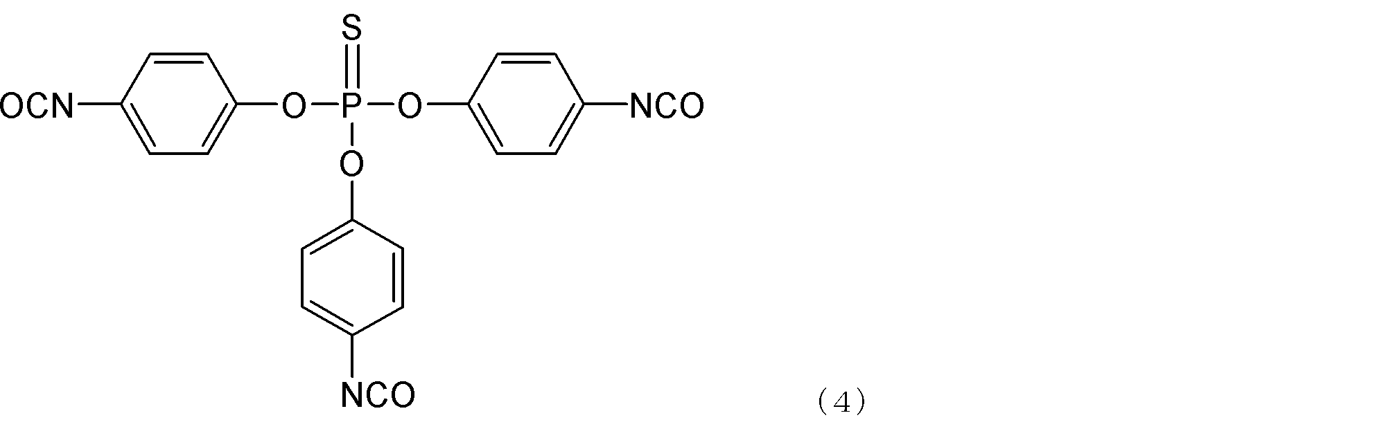

本開示の一態様に係る清掃部材は、例えば、電子写真画像形成装置用のクリーニングブレードとして用いることができる。電子写真用クリーニングブレードが適用される被清掃部材としては、感光体などの像担持体、中間転写ベルトなどの無端状のベルト等が挙げられる。以下、被清掃部材として像担持体を例として、清掃部材の実施形態について詳細に説明するが、これに限定されるものではない。
支持部材は、図2に示すように電子写真画像形成装置内において、弾性部材2の先端が、被清掃部材としての電子写真感光ドラム6の表面に当接するように支持する部材3である。そのような機能を奏する限り、支持部材の構成は特に限定されるものではない。また、材質についても、当該機能を奏する限り特に限定されず、例えば以下の材料を挙げることができる。鋼板、ステンレス鋼板、亜鉛めっき鋼板、クロムフリー鋼板の如き金属材料、6-ナイロン、6,6-ナイロンの如き樹脂。
本開示に係るクリーニングブレードの製造方法は、特に限定されず、公知の方法の中から適したものを選択すればよい。例えば、クリーニングブレード用金型の内面に離型剤を塗布し、支持部材を配置した後、上記ポリウレタン原料組成物を注入し、加熱して硬化させることにより、板状の弾性部材(ブレード部材)と支持部材とが一体化したクリーニングブレードを得ることができる。
ポリウレタン原料組成物を硬化させる際には、例えば100~180℃で、1~5分程度硬化させることが好ましい。
上記クリーニングブレードは、電子写真画像形成装置に着脱可能に構成されているプロセスカートリッジに組み込んで使用することができる。具体的には、例えば、被クリーニング部材としての像担持体と、像担持体の表面をクリーニング可能に配置されているクリーニングブレードとを具備しているプロセスカートリッジにおいて、クリーニングブレードとして本態様に係るクリーニングブレードを用いることができる。かかるプロセスカートリッジは、高品位な電子写真の安定的な形成に資するものである。
本開示に係る清掃部材は、被清掃部材の表面を払拭する車両用ワイパーブレードとして使用することができる。すなわち、清掃部材は、車両のウインドシールドなどの被清掃部材におけるワイパー装置用の車両用ワイパー部材であることが好ましい。車両用ワイパーブレードは、自動車、電車、船舶、及び航空機などに対して、フロントガラスやリアガラスなどのガラス面に付着した水滴や汚れなどを払拭して操縦者の視界を確保するために用いられる。このとき車両用ワイパーブレードに用いられる清掃部材には、液体系の付着物や排気ガス中に含まれる微粒子やアスファルトなどの粉塵など多様化する清掃対象物を、曲率が大きい部分と小さい部分を有するガラス面から払拭するための、充分な追従性が求められる。また、付着力の強い清掃対象物をガラス面から払拭するにあたり、熱暑環境下での使用及び使用期間長期化に伴う清掃部材の高温化によって生じる、ビビリを抑制することが求められる。
車両用ワイパーブレードの製造方法は、特に限定されず、公知の方法の中から選択することができる。例えば、車両用ワイパーブレード用金型内に、ポリウレタンエラストマー原料組成物を注入し、加熱して硬化させることにより、テーパー部を有するリップ部を得ることができる。
本開示の車両用ワイパーブレードは、タンデム式、対向払拭式といった様々な形式のワイパー装置に使用することができる。
本開示に係る払拭用の清掃部材は、被清掃部材の表面に弾性部材を当接させて、被清掃部材の表面を清掃する。窓ガラスやタイル、壁、レンズ、ソーラーパネルに代表されるような面を清掃するための清掃用ワイパーブレードとして使用することができる。清掃用ワイパーブレードは被清掃面に対して押圧を強くしなくても、拭きムラを抑制する充分な追従性が求められる。また、付着力の強い清掃対象物を被清掃面から払拭するにあたり、押圧を強くすることに伴う該清掃部材の高温化による、ビビリを抑制することが求められる。
清掃用ワイパーブレードの弾性部材の製造方法は、特に限定されず、公知の方法の中から選択することができる。例えば、清掃用ワイパーブレードの弾性部用金型内に、ポリウレタンエラストマー原料組成物を注入し、加熱して硬化させることにより清掃用ワイパーブレードの弾性部材を得ることができる。
清掃用ワイパーブレードの使用方法について説明する。清掃作業主体は、グリップ部31又は支持グリップ部34を保持し、弾性部材32を被清掃部材の表面に押しつけながら、弾性部材32が延びる方向と交差する方向に清掃用ワイパーブレードを動かして、汚れを除去する。図6に清掃時に、清掃用ワイパーブレードが被清掃部材35に接触し摺動させ清掃する過程の状態の説明図を示す。
清掃用ワイパーブレードにおいて、弾性部材32、弾性部材支持部33及びグリップ部31又は支持グリップ部34のそれぞれの形状及び取り付け方は、限定されない。また、弾性部材32に対する弾性部材支持部33の取り付け方、弾性部材支持部33に対するグリップ部31又は支持グリップ部34の取り付け方についても、限定されない。
この実施例においては、図1に示す一体成型タイプのクリーニングブレードを製造して評価した。なお、実施例及び比較例中の「部」は特に断りが無い場合、すべて質量基準である。
〔支持部材〕
厚さ1.6mmの亜鉛めっき鋼板を用意し、これを加工して、図2の符号3で示す、断面がL字形状の支持部材を得た。なお、この支持部材の弾性部材が接触する箇所に、ウレタン-金属の一層型接着剤(商品名;ケムロック219、ロード・コーポレーション社製)を塗布した。
下記表1に記載の材料を混合し、温度80℃で3時間反応させ、NCO含量が10.2質量%のプレポリマーを得た。
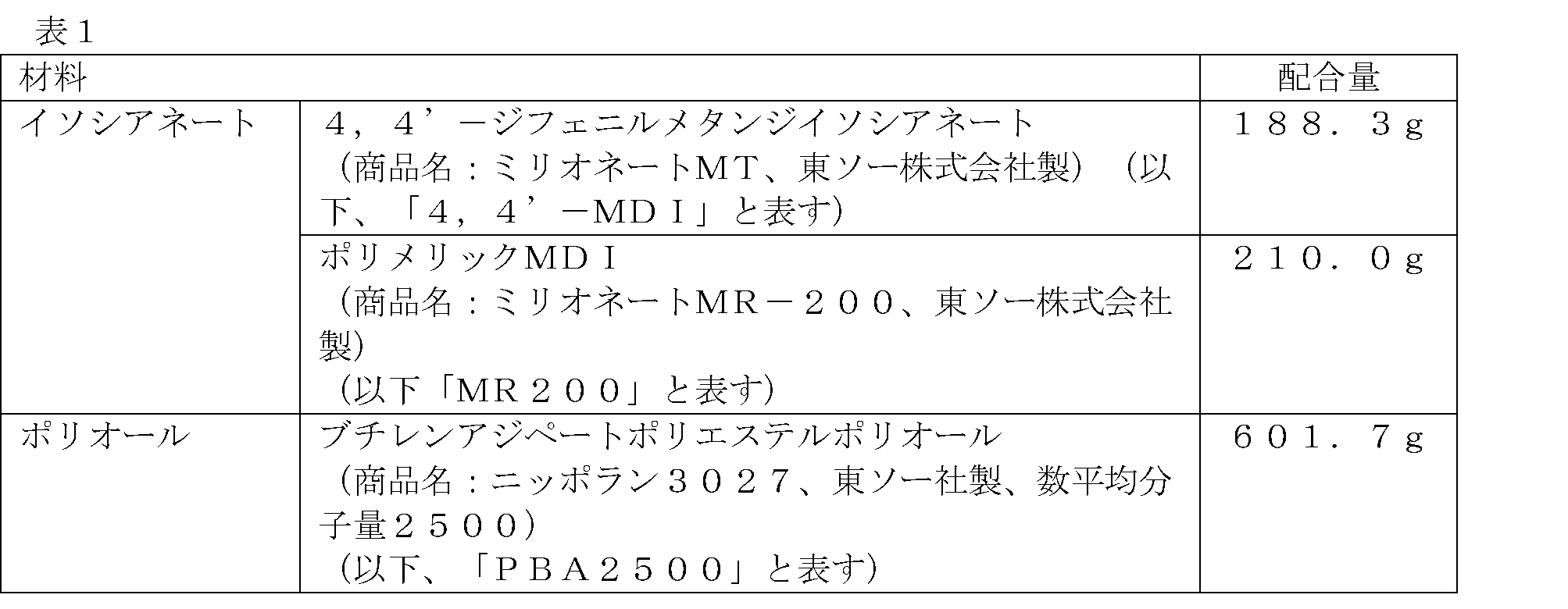

上記支持部材の接着剤塗布箇所を、クリーニングブレード用成形金型のキャビティ内に突出する様に配置した(製法I)。そして、前記原料組成物をキャビティ内に注入し、温度130℃で2分間硬化させた。その後に脱型して、ポリウレタンと支持部材との一体成型体を得た。
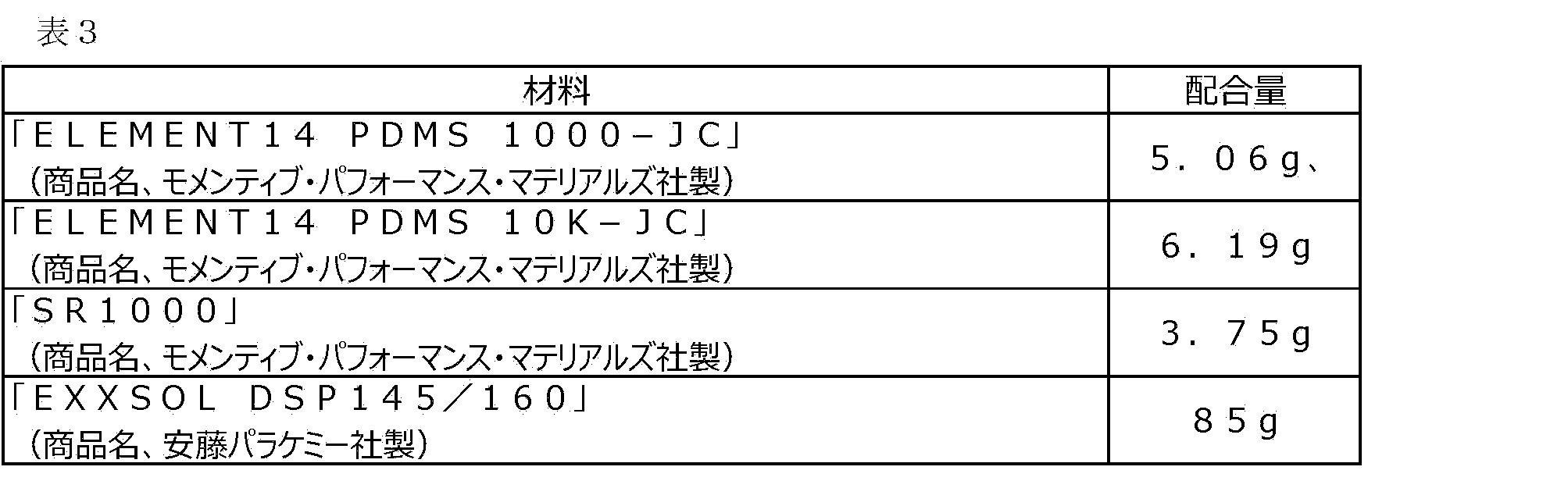
日本産業規格(JIS) K 6394:2007(「加硫ゴム及び熱可塑性ゴム-動的性質の求め方-一般指針」に準拠して損失係数tanδ(粘弾性)を測定した。
測定条件を以下に記す。
装置:動的粘弾性測定装置(商品名:DMA EXPLEXOR 500N、ネッチ(NETZSCH)社製;
静歪:2%;
動歪:0.5%;
測定温度:-20℃~60℃;
測定周波数:10Hz。
なお、損失係数tanδ測定用試料の作製は以下のように行った。
弾性部材における、被清掃部材との当接部の角を含むように試料を作製した。0.5mm、1.0mm、30mmの直方体上に切り出して作製した。
サンプルを、ガスクロマトグラフ(GC)を通さずにイオン源に直接導入する直接試料導入法(DI法)を用いて分析してM1~M3を算出した。
装置としては、イオントラップ型GC/MS(商品名:POLARIS Q、サーモフィッシャーサイエンティフィック社製)を使用し、直接導入プローブとしては、ダイレクト・エクスポージャー・プローブ(Direct Exposure Probe(DEP))を用いた。被清掃部材との当接部表面を下記方法にて測定した。なお、サンプリングでは、ポリウレタンなどの部材をバイオカッターで切り取った。具体的には、被清掃部材との当接部を含むように切り出した。当接部が複数個所存在する場合は、各々の箇所から切り出した。
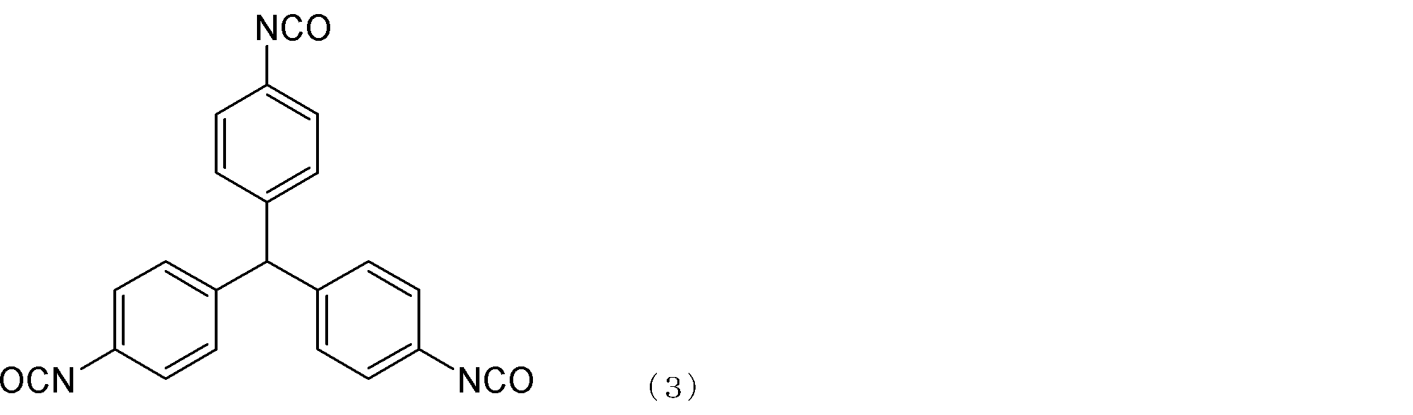
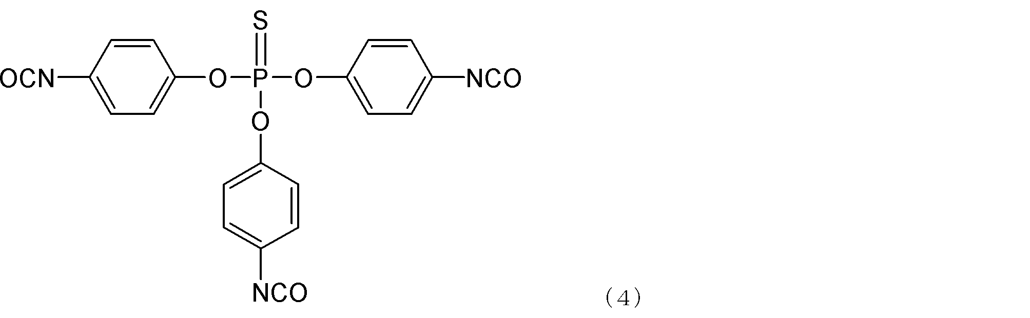
実施例1のクリーニングブレードをカラーレーザービームプリンター(商品名;HP LaserJet Enterprise Color M553dn、HP社製)のシアンカートリッジに、被クリーニング部材である感光ドラムのクリーニングブレードとして組み込んだ。また、該シアンカートリッジの現像機のトナーを、後述のトナー1に全量入れ替えた。
また、廃トナーは適時、カートリッジ背面に穴を開けて吸い出しながら、評価を行った。得られた画像について以下の評価基準により性能をランク付けした。
A:クリーニングブレード起因の画像不良(画像上スジ)が通常評価でも2倍評価でも発生しない。
B:クリーニングブレード起因の画像不良(画像上スジ)が通常評価では発生せず、2倍評価でごく軽微に発生(スジ長さが5mm以下)。
C:クリーニングブレード起因の画像不良(画像上スジ)が通常評価では発生しないが、2倍評価では発生(10mmを超える)。または通常評価でも発生する。
実施例1のクリーニングブレードをカラーレーザービームプリンター(商品名;HP LaserJet Enterprise Color M553dn、ヒューレット・パッカード社製)のシアンカートリッジに、被クリーニング部材である感光ドラムのクリーニングブレードとして組み込んだ。また、該シアンカートリッジの現像機のトナーを、後述のトナー1に全量入れ替えた。
同環境下において評価を行うと、レーザービームプリンター自身の動作熱やクリーニングブレード当接部における摩擦熱により、クリーニングブレードの弾性部材温度が上昇し、55℃に達する。そのため高温でのビビリ評価を行うことが可能となる。
また、廃トナーは適時、カートリッジ背面に穴を開けて吸い出しながら、評価を行った。得られた画像について以下の評価基準により性能をランク付けした。
A:クリーニングブレード起因の画像不良(画像上スジ)が通常評価でも2倍評価でも発生せず、異音も発生しない。
B:クリーニングブレード起因の画像不良(画像上スジ)が通常評価では発生せず、2倍評価でごく軽微に発生(スジ長さが5mm以下)。異音は発生しない。
C:クリーニングブレード起因の画像不良(画像上スジ)が通常評価では発生しないが、2倍評価では発生(10mmを超える)。または通常評価でも発生する。または異音が発生する。
なお、以下に於いて、「部」は特に断りが無い場合、すべて質量基準である。
(水系媒体1の調製工程)
撹拌機、温度計、還流管を具備した反応容器中にイオン交換水650.0部に、リン酸ナトリウム(ラサ工業社製・12水和物)14.0部を投入し、窒素パージしながら65℃で1.0時間保温した。T.K.ホモミクサー(特殊機化工業株式会社製)を用いて、15000rpmにて攪拌しながら、イオン交換水10.0部に9.2部の塩化カルシウム(2水和物)を溶解した塩化カルシウム水溶液を一括投入し、分散安定剤を含む水系媒体を調製した。さらに、水系媒体に10質量%塩酸を投入し、pHを5.0に調整し、水系媒体1を得た。
・スチレン :60.0部
・C.I.ピグメントブルー15:3 :6.5部
前記材料をアトライタ(三井三池化工機株式会社製)に投入し、さらに直径1.7mmのジルコニア粒子を用いて、220rpmで5.0時間分散させて、顔料分散液を調製した。前記顔料分散液に下記材料を加えた。
・スチレン :20.0部
・n-ブチルアクリレート :20.0部
・架橋剤(ジビニルベンゼン) :0.3部
・飽和ポリエステル樹脂 :5.0部
(プロピレンオキサイド変性ビスフェノールA(2モル付加物)とテレフタル酸との重縮合物(モル比10:12)、ガラス転移温度Tg=68℃、重量平均分子量Mw=10000、分子量分布Mw/Mn=5.12)
・フィッシャートロプシュワックス(融点78℃) :7.0部
これを65℃に保温し、T.K.ホモミクサー(特殊機化工業株式会社製)を用いて、500rpmにて均一に溶解、分散し、重合性単量体組成物を調製した。
水系媒体1の温度を70℃、T.K.ホモミクサーの回転数を15000rpmに保ちながら、水系媒体1中に重合性単量体組成物を投入し、重合開始剤であるt-ブチルパーオキシピバレート10.0部を添加した。そのまま該撹拌装置にて15000rpmを維持しつつ10分間造粒した。
造粒工程の後、攪拌機をプロペラ撹拌羽根に換え150rpmで攪拌しながら70℃を保持して5.0時間重合を行い、85℃に昇温して2.0時間加熱することで重合反応を行った。
その後、反応容器の還流管を冷却管に付け替え、スラリーを100℃まで加熱することで、蒸留を6時間行い未反応の重合性単量体を留去し、トナー母粒子分散液を得た。
撹拌機、温度計を備えた反応容器に、イオン交換水60.0部を秤量し、10質量%の塩酸を用いてpHを4.0に調整した。これを撹拌しながら加熱し、温度を40℃にした。
その後、有機ケイ素化合物であるメチルトリエトキシシラン40.0部を添加して2時間以上撹拌して加水分解を行った。加水分解の終点は目視にて油水が分離せず1層になったことで確認を行い、冷却して有機ケイ素化合物の加水分解液を得た。
得られたトナー母粒子分散液の温度を55℃に冷却したのち、有機ケイ素化合物の加水分解液を25.0部添加して有機ケイ素化合物の重合を開始した。そのまま15分保持した後に、3.0質量%炭酸水素ナトリウム水溶液で、pHを5.5に調整した。55℃で撹拌を継続したまま、60分間保持したのち、3.0質量%炭酸水素ナトリウム水溶液を用いてpHを9.5に調整し、更に240分間保持してトナー粒子分散液を得た。
重合工程終了後、トナー粒子分散液を冷却し、トナー粒子分散液に塩酸を加えpH=1.5以下に調整して1時間撹拌放置してから加圧ろ過器で固液分離し、トナーケーキを得た。これをイオン交換水でリスラリーして再び分散液とした後に、前述のろ過器で固液分離してトナーケーキを得た。
得られたトナーケーキを40℃の恒温槽にて72時間かけて乾燥・分級を行い、トナー1を得た。
触媒としてRX3(商品名TOYOCAT-RX3、東ソー株式会社製)を1.32g使用し、RX5を使用しない以外は実施例1と同様に行った。
硬化剤として、TMPを43.1g、PHA1000を244.3g、Polycat46を0.13g、RX5を1.01g混合して硬化剤を作製した。
金型は、前記ポリウレタンエラストマー組成物を注入する前に、離型剤Bを塗布したものを用いた。離型剤Bは、ELEMENT14 PDMS 1000-JC 3.04g(商品名、モメンティブ・パフォーマンス・マテリアルズ社製)、ELEMENT14 PDMS 10K-JC 3.71g(商品名、モメンティブ・パフォーマンス・マテリアルズ社製)、SR1000 8.25g(商品名、モメンティブ・パフォーマンス・マテリアルズ社製)、EXXSOL DSP145/160 85gを混合したものを用いた。
表4~表5に示した通りに各種材料種類、配合量、製法とした以外は実施例1又は3と同様にして、実施例4~14のクリーニングブレード及び比較例1~2のクリーニングブレードを得た。実施例1と同様に物性の測定及び評価を行った結果を表4~表5に示す。
<車両用ワイパーブレード用原料の調製>
実施例1と同様に行った。
<車両用ワイパーブレードの製造>
車両用ワイパーブレード用成形金型内に、調整した前記車両用ワイパーブレード用原料組成物を注入し、130℃で2分間硬化させた後に脱型して、ポリウレタンを得た。金型は、前記原料組成物を注入する前に、実施例1と同様に離型剤Aを塗布したものを用いた。
このポリウレタンのリップ部先端側を、適宜切断して、ワイパーブレードを得た。
リップ部先端の厚み方向および長手方向の距離をそれぞれ0.6mm、450mmとした。ネック部の厚み方向および短手方向の距離を0.7mm、0.5mmとし、ショルダー部の厚み方向の距離を3.0mmとした。得られたワイパーブレードは以下の方法によって評価した。
実施例1と同様に行った。
<M1、M2及びM3の算出>
実施例1と同様に行った。
JIS D5710に記載されている払拭性能試験の試験装置を用い、車両用ワイパーブレードの追従性の評価を行った。この試験は、まず車両用ワイパーブレードを試験装置に取り付け、被清掃部材であるガラス面に油膜を模した状態としてシリコーンオイル(商品名:KF-96-50cs、信越化学工業社製)を払拭面全体に塗布する。次いで、該試験装置を低温、低湿度環境(温度15℃、相対湿度10%)下で24時間放置した後、下記条件で清掃を行った。
車両用ワイパーブレードを1往復させた後のガラス面上の拭き残り状態を清掃面の裏側より観察し、光沢ムラ、視界への影響を目視で確認した。結果を、車両用ワイパーブレードにより払拭される面の面積に対するシリコーンオイル膜が除去された部分の面積の割合(以下、シリコーンオイル膜除去面積率(%)と称す)として算出した。
算出した油膜除去面積率から下記基準により追従性能の評価を実施した。
車両用ワイパーブレードに加える荷重:10N/m
車両用ワイパーブレードの払拭往復速度:50回/分
〔評価基準〕
ランクA:シリコーンオイル膜除去面積率が95%以上
ランクB:シリコーンオイル膜除去面積率が90%以上95%未満
ランクC:シリコーンオイル膜除去面積率が85%未満90%未満
ランクD:シリコーンオイル膜除去面積率が85%未満
該試験機の放置環境を高温、高湿度環境(温度50℃、相対湿度70%)としたこと、そして評価基準を耳による異音の発生確認にしたこと以外は追従性の評価と同様の操作を行い、ビビリを評価した。放置環境を高温、高湿度環境にすることで、車両用ワイパーブレードの当接部を軟化させた。そして、ガラス面に対する接触面積を増加させることで摩擦力を増加させ、車両用ワイパーブレードの当接部温度を摩擦力による発熱により55℃まで昇温させた。
〔評価基準〕
ランクA:異音が発生しない
ランクB:異音がほとんど発生しない
ランクC:異音が発生する
硬化剤用の材料とその配合量を表6に記載した通りとした以外は実施例15と同様にして車両用ワイパーブレードを作製し、評価した。
ショルダー部を有する形状となるようなキャビティ形状の成形用型を用いた以外は実施例15と同様にして、ブレード支持部、リップ部、及びネック部を有する車両用ワイパーブレードを製造し、評価した。
ネック部、ショルダー部を有する形状となるようなキャビティ形状の成形用型を用いた以外は実施例15と同様にして、ブレード支持部及びリップ部を有する車両用ワイパーブレードを製造し、評価した。
プレポリマー用の各種材料の種類とその使用量、及び/または、硬化剤用の各種材料の種類とその使用量を表7に示す通りとした以外は実施例15と同様にして車両用ワイパーブレードを作製し、評価した。
プレポリマー用の各種材料の種類とその使用量、及び/または、硬化剤用の各種材料の種類とその使用量を表7に示す通りとした以外は実施例15と同様にして車両用ワイパーブレードを作製し、評価した。
<清掃用ワイパーブレード用原料の調製>
実施例1と同様に行った。
<清掃用ワイパーブレードの製造>
清掃用ワイパーブレード弾性部用成形金型内に、調整した前記清掃用ワイパーブレード用原料を注入し、130℃で2分間硬化させた後に脱型して、ポリウレタン成型体を得た。金型は、前記ポリウレタンエラストマー組成物を注入する前に、実施例1と同様に離型剤Aを塗布したものを用いた。
得られたポリウレタン成型体の先端側を、適宜切断して先端面を作製し、清掃用ワイパーブレード弾性部を得た。清掃用ワイパーブレード弾性部の厚み方向、短手方向及び長手方向の距離をそれぞれ1.8mm、20mm、300mmとした。得られた清掃用ワイパーブレードは以下の方法によって評価した。
実施例1と同様に行った。
<M1、M2及びM3の算出>
実施例1と同様に行った。
ガラス面上に清掃用ワイパーブレードの弾性部材を接触させ、引き戻し移動する往復行程で摺接することにより、ガラス面上の汚れの払拭状態を観察することで清掃用ワイパーブレードの追従性の評価を行った。図7に評価を行った試験機の概略図を示す。
清掃用ワイパーブレード長:300mm
ガラス板移動速度:10mm/sec
〔評価基準〕
ランクA:油膜除去面積率が95%以上
ランクB:油膜除去面積率が90%以上95%未満
ランクC:油膜除去面積率が90%未満
該試験機の放置環境を高温、高湿度環境(温度50℃、相対湿度70%)としたこと、そして評価基準を耳による異音の発生確認にしたこと以外は追従性の評価と同様の操作を行い、ビビリを評価した。放置環境を高温、高湿度環境にすることで、清掃用ワイパーブレードの当接部を軟化させた。そして、ガラス面に対する接触面積を増加させることで摩擦力を増加させ、清掃用ワイパーブレードの当接部温度を55℃に昇温させた。
〔評価基準〕
ランクA:異音が発生しない
ランクB:異音がほとんど発生しない
ランクC:異音が発生する
プレポリマー用の各種材料の種類とその使用量、及び/または、硬化剤用の各種材料の種類とその使用量を表8~表9に示す通りとした以外は実施例31と同様にして清掃用ワイパーブレードを作製し、評価した。
プレポリマー用の各種材料の種類とその使用量、及び/または、硬化剤用の各種材料の種類とその使用量を表9に示す通りとした以外は実施例31と同様にして清掃用ワイパーブレードを作製し、評価した。
プレポリマー用の各種材料の種類とその使用量、及び/または、硬化剤用の各種材料の種類とその使用量を表10に示す通りとした以外は実施例1と同様にしてポリウレタン弾性体を作製し、各種物性を測定した。その結果を表10に示す。

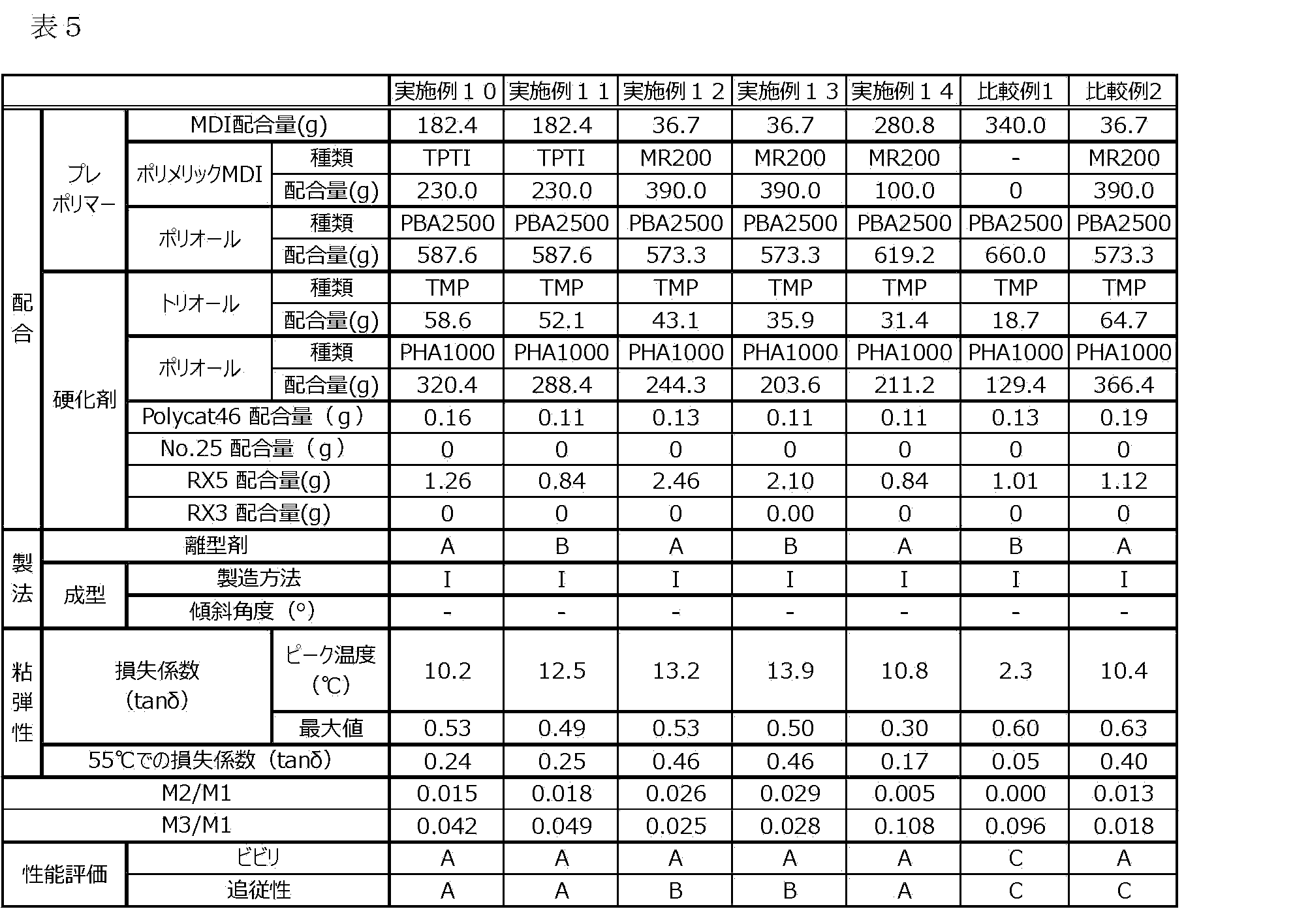
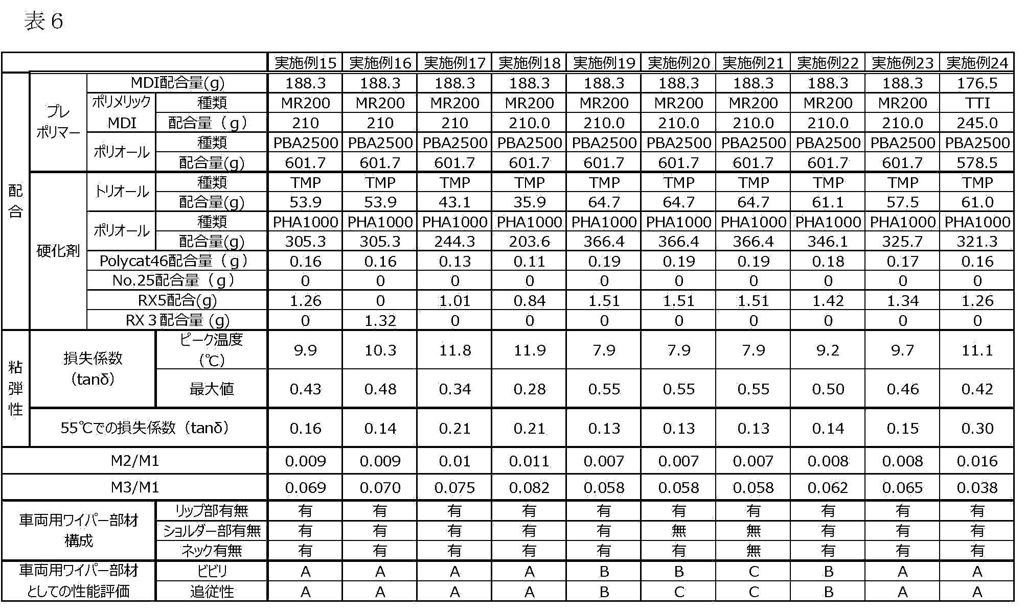

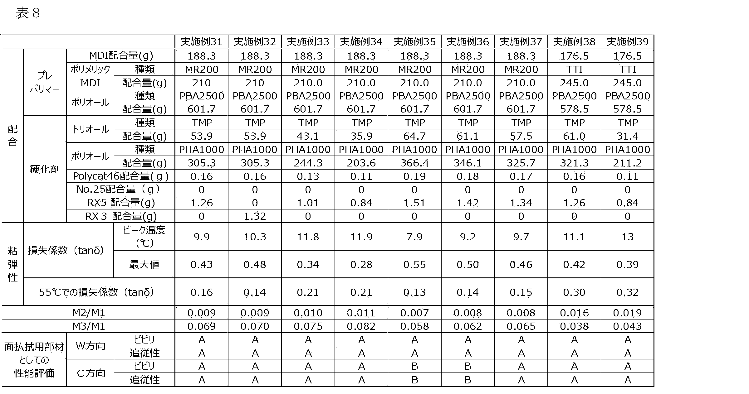


(構成1)
ポリウレタンを含む弾性部材を備え、被清掃部材の表面に該弾性部材の少なくとも一部を当接させて、該被清掃部材の表面を清掃する清掃部材であって、
該弾性部材から、該被清掃部材と当接する部分を含むようにサンプリングした試料の損失係数tanδを温度-20℃~+60℃の範囲で測定したとき、
tanδの最大値を示すピークのピーク温度が、15.0℃以下に存在し、tanδの最大値が、0.20以上0.55以下であり、
温度55℃におけるtanδが、0.13以上であり、かつ、
該弾性部材から、該被清掃部材と当接する部分を含むようにサンプリングした試料をイオン化室内で加熱気化させ、該試料を構成する分子をイオン化する直接試料導入方式の質量分析計を用いて、昇温速度10℃/秒で1000℃まで加熱したときに得られる全てのイオンの検出量をM1とし、イソシアネート基を3個以上有する多官能イソシアネートに由来するm/z値の範囲に対応する抽出イオンサーモグラムのピークの積分強度をM2としたとき、
M2/M1が0.001以上であることを特徴とする清掃部材。
(構成2)
M2/M1が、0.001以上、0.035以下である、構成1に記載の清掃部材。
(構成3)
前記ポリウレタンが、
ジイソシアネート及びイソシアネート基を3個以上有する多官能イソシアネートを含むイソシアネート化合物、並びに、
3官能以上の多官能アルコールを含むアルコール
を含む組成物の反応物を含む、構成1又は2に記載の清掃部材。
(構成4)
前記試料をイオン化室内で加熱気化させ、該試料を構成する分子をイオン化する直接試料導入方式の質量分析計を用いて、昇温速度10℃/秒で1000℃まで加熱したときに得られる前記ジイソシアネートに由来するm/z値の範囲に対応する抽出イオンサーモグラムのピークの積分強度をM3としたとき、M3/M1が、0.025~0.130である、構成3に記載の清掃部材。
(構成5)
前記多官能イソシアネートが、ポリメリックMDI、トリフェニルメタン-4,4’,4’’-トリイソシアネート、及びトリス(フェニルイソシアネート)チオホスフェートからなる群から選択される少なくとも一である、構成1~4のいずれかに記載の清掃部材。
(構成6)
前記ジイソシアネートが、4,4’-ジフェニルメタンジイソシアネート、2,4-トリレンジイソシアネート、2,6-トリレンジイソシアネート、キシレンジイソシアネート、1,5-ナフチレンジイソシアネート、p-フェニレンジイソシアネート、ヘキサメチレンジイソシアネート、イソホロンジイソシアネート、4,4’-ジシクロヘキシルメタンジイソシアネート、テトラメチルキシレンジイソシアネート、カルボジイミド変性ジフェニルメタンジイソシアネートからなる群から選択される少なくとも一つである、構成3又は4に記載の清掃部材。
(構成7)
前記清掃部材が、電子写真用クリーニングブレードである、構成1~6のいずれかに記載の清掃部材。
(構成8)
前記弾性部材を支持する支持部材をさらに具備する、構成7に記載の清掃部材。
(構成9)
前記清掃部材が、車両のウインドシールドのワイパー装置用の車両用ワイパー部材である、構成1~6のいずれかに記載の清掃部材。
(構成10)
前記車両用ワイパー部材が、少なくとも車両用ワイパー支持部と前記ウインドシールドの表面と当接するリップ部と、を具備する、構成9に記載の清掃部材。
(構成11)
前記車両用ワイパー部材が、少なくとも車両用ワイパー支持部と前記ウインドシールドの表面と当接するリップ部と、該リップ部の車両用ワイパー支持部側にショルダー部を具備する、構成9又は10に記載の清掃部材。
(構成12)
前記車両用ワイパー部材が、少なくとも車両用ワイパー支持部と、該車両用ワイパー支持部にネックを介して揺動可能に連結されてなるリップ部と、を具備することを特徴とする、構成9~11のいずれかに記載の清掃部材。
(構成13)
前記清掃部材が、被清掃部材の表面に前記弾性部材を当接させて、該被清掃部材の表面を清掃する払拭用の清掃部材である、構成1~6のいずれかに記載の清掃部材。
(構成14)
前記清掃部材が、前記被清掃部材の表面と当接する前記弾性部材と、前記弾性部材の長手方向にわたって前記弾性部材を支持する弾性部材支持部を有する、構成13に記載の清掃部材。
(構成15)
ポリウレタンを含む弾性部材であって、
該弾性部材からサンプリングした試料の損失係数tanδを、温度-20℃~+60℃の範囲で測定したとき、
tanδの最大値を示すピークのピーク温度が、15.0℃以下に存在し、該tanδの最大値が、0.20以上0.55以下であり、
温度55℃におけるtanδが、0.13以上であり、かつ、
該弾性部材からサンプリングした試料をイオン化室内で加熱気化させ、該試料を構成する分子をイオン化する直接試料導入方式の質量分析計を用いて、昇温速度10℃/秒で1000℃まで加熱したときに得られる全てのイオンの検出量をM1とし、イソシアネート基を3個以上有する多官能イソシアネートに由来するm/z値の範囲に対応する抽出イオンサーモグラムのピークの積分強度をM2としたとき、
M2/M1が0.001以上であることを特徴とする弾性部材。
(構成16)
M2/M1が、0.001以上、0.035以下である、構成15に記載の弾性部材。
(構成17)
前記ポリウレタンが、
ジイソシアネート及びイソシアネート基を3個以上有する多官能イソシアネートを含むイソシアネート化合物、並びに、
3官能以上の多官能アルコールを含むアルコール
を含む組成物の反応物を含む、構成15又は16に記載の弾性部材。
(構成18)
前記試料をイオン化室内で加熱気化させ、該試料を構成する分子をイオン化する直接試料導入方式の質量分析計を用いて、昇温速度10℃/秒で1000℃まで加熱したときに得られる前記ジイソシアネートに由来するm/z値の範囲に対応する抽出イオンサーモグラムのピークの積分強度をM3としたとき、M3/M1が、0.025~0.130である、構成15~17のいずれかに記載の弾性部材。
本願は、2021年6月4日提出の日本国特許出願特願2021-094304及び2022年5月12日提出の日本国特許出願2022-079036を基礎として優先権を主張するものであり、その記載内容の全てをここに援用する。
11:車両用ワイパー支持部、12:ネック、13:リップ部(先端部)、15:第1のリップ面、16:第2のリップ面、17:先端面18:第1のエッジ、19:第2のエッジ、50:被清掃部材
31:グリップ部、32:弾性部材、33:弾性部材支持部、34:支持グリップ部、35:被清掃部材、36:リップ面、38:先端面
113:弾性部材、114:ガラス板、115:電動ロボシリンダ
Claims (18)
- ポリウレタンを含む弾性部材を備え、被清掃部材の表面に該弾性部材の少なくとも一部を当接させて、該被清掃部材の表面を清掃する清掃部材であって、
該弾性部材から、該被清掃部材と当接する部分を含むようにサンプリングした試料の損失係数tanδを温度-20℃~+60℃の範囲で測定したとき、
tanδの最大値を示すピークのピーク温度が、15.0℃以下に存在し、tanδの最大値が、0.20以上0.55以下であり、
温度55℃におけるtanδが、0.13以上であり、かつ、
該弾性部材から、該被清掃部材と当接する部分を含むようにサンプリングした試料をイオン化室内で加熱気化させ、該試料を構成する分子をイオン化する直接試料導入方式の質量分析計を用いて、昇温速度10℃/秒で1000℃まで加熱したときに得られる全てのイオンの検出量をM1とし、イソシアネート基を3個以上有する多官能イソシアネートに由来するm/z値の範囲に対応する抽出イオンサーモグラムのピークの積分強度をM2としたとき、
M2/M1が0.001以上であることを特徴とする清掃部材。 - M2/M1が、0.001以上、0.035以下である請求項1に記載の清掃部材。
- 前記ポリウレタンが、
ジイソシアネート及びイソシアネート基を3個以上有する多官能イソシアネートを含むイソシアネート化合物、並びに、
3官能以上の多官能アルコールを含むアルコール
を含む組成物の反応物を含む請求項1に記載の清掃部材。 - 前記試料をイオン化室内で加熱気化させ、該試料を構成する分子をイオン化する直接試料導入方式の質量分析計を用いて、昇温速度10℃/秒で1000℃まで加熱したときに得られる前記ジイソシアネートに由来するm/z値の範囲に対応する抽出イオンサーモグラムのピークの積分強度をM3としたとき、M3/M1が、0.025~0.130である請求項3に記載の清掃部材。
- 前記多官能イソシアネートが、ポリメリックMDI、トリフェニルメタン-4,4’,4’’-トリイソシアネート、及びトリス(フェニルイソシアネート)チオホスフェートからなる群から選択される少なくとも一である請求項3に記載の清掃部材。
- 前記ジイソシアネートが、4,4’-ジフェニルメタンジイソシアネート、2,4-トリレンジイソシアネート、2,6-トリレンジイソシアネート、キシレンジイソシアネート、1,5-ナフチレンジイソシアネート、p-フェニレンジイソシアネート、ヘキサメチレンジイソシアネート、イソホロンジイソシアネート、4,4’-ジシクロヘキシルメタンジイソシアネート、テトラメチルキシレンジイソシアネート、カルボジイミド変性ジフェニルメタンジイソシアネートからなる群から選択される少なくとも一つである請求項3に記載の清掃部材。
- 前記清掃部材が、電子写真用クリーニングブレードである請求項1~6のいずれか一項に記載の清掃部材。
- 前記弾性部材を支持する支持部材をさらに具備する請求項7に記載の清掃部材。
- 前記清掃部材が、車両のウインドシールドのワイパー装置用の車両用ワイパー部材である請求項1~6のいずれか一項に記載の清掃部材。
- 前記車両用ワイパー部材が、少なくとも車両用ワイパー支持部と前記ウインドシールドの表面と当接するリップ部と、を具備する請求項9に記載の清掃部材。
- 前記車両用ワイパー部材が、少なくとも車両用ワイパー支持部と前記ウインドシールドの表面と当接するリップ部と、該リップ部の車両用ワイパー支持部側にショルダー部を具備する請求項9に記載の清掃部材。
- 前記車両用ワイパー部材が、少なくとも車両用ワイパー支持部と、該車両用ワイパー支持部にネックを介して揺動可能に連結されてなるリップ部と、を具備することを特徴とする請求項9に記載の清掃部材。
- 前記清掃部材が、被清掃部材の表面に前記弾性部材を当接させて、該被清掃部材の表面を清掃する払拭用の清掃部材である請求項1~6のいずれか一項に記載の清掃部材。
- 前記清掃部材が、前記被清掃部材の表面と当接する前記弾性部材と、前記弾性部材の長手方向にわたって前記弾性部材を支持する弾性部材支持部を有する請求項13に記載の清掃部材。
- ポリウレタンを含む弾性部材であって、
該弾性部材からサンプリングした試料の損失係数tanδを、温度-20℃~+60℃の範囲で測定したとき、
tanδの最大値を示すピークのピーク温度が、15.0℃以下に存在し、該tanδの最大値が、0.20以上0.55以下であり、
温度55℃におけるtanδが、0.13以上であり、かつ、
該弾性部材からサンプリングした試料をイオン化室内で加熱気化させ、該試料を構成する分子をイオン化する直接試料導入方式の質量分析計を用いて、昇温速度10℃/秒で1000℃まで加熱したときに得られる全てのイオンの検出量をM1とし、イソシアネート基を3個以上有する多官能イソシアネートに由来するm/z値の範囲に対応する抽出イオンサーモグラムのピークの積分強度をM2としたとき、
M2/M1が0.001以上であることを特徴とする弾性部材。 - M2/M1が、0.001以上、0.035以下である請求項15に記載の弾性部材。
- 前記ポリウレタンが、
ジイソシアネート及びイソシアネート基を3個以上有する多官能イソシアネートを含むイソシアネート化合物、並びに、
3官能以上の多官能アルコールを含むアルコール
を含む組成物の反応物を含む請求項15に記載の弾性部材。 - 前記試料をイオン化室内で加熱気化させ、該試料を構成する分子をイオン化する直接試料導入方式の質量分析計を用いて、昇温速度10℃/秒で1000℃まで加熱したときに得られる前記ジイソシアネートに由来するm/z値の範囲に対応する抽出イオンサーモグラムのピークの積分強度をM3としたとき、M3/M1が、0.025~0.130である請求項17に記載の弾性部材。
Priority Applications (3)
| Application Number | Priority Date | Filing Date | Title |
|---|---|---|---|
| CN202280039816.8A CN117460584A (zh) | 2021-06-04 | 2022-05-25 | 清扫构件和弹性构件 |
| EP22815934.9A EP4349501A4 (en) | 2021-06-04 | 2022-05-25 | Cleaning member and elastic member |
| US18/519,423 US12174576B2 (en) | 2021-06-04 | 2023-11-27 | Cleaning member and elastic member |
Applications Claiming Priority (4)
| Application Number | Priority Date | Filing Date | Title |
|---|---|---|---|
| JP2021094304 | 2021-06-04 | ||
| JP2021-094304 | 2021-06-04 | ||
| JP2022079036A JP7786825B2 (ja) | 2021-06-04 | 2022-05-12 | 清掃部材及び弾性部材 |
| JP2022-079036 | 2022-05-12 |
Related Child Applications (1)
| Application Number | Title | Priority Date | Filing Date |
|---|---|---|---|
| US18/519,423 Continuation US12174576B2 (en) | 2021-06-04 | 2023-11-27 | Cleaning member and elastic member |
Publications (1)
| Publication Number | Publication Date |
|---|---|
| WO2022255184A1 true WO2022255184A1 (ja) | 2022-12-08 |
Family
ID=84323142
Family Applications (1)
| Application Number | Title | Priority Date | Filing Date |
|---|---|---|---|
| PCT/JP2022/021388 Ceased WO2022255184A1 (ja) | 2021-06-04 | 2022-05-25 | 清掃部材及び弾性部材 |
Country Status (3)
| Country | Link |
|---|---|
| US (1) | US12174576B2 (ja) |
| EP (1) | EP4349501A4 (ja) |
| WO (1) | WO2022255184A1 (ja) |
Cited By (1)
| Publication number | Priority date | Publication date | Assignee | Title |
|---|---|---|---|---|
| US12174576B2 (en) | 2021-06-04 | 2024-12-24 | Canon Kabushiki Kaisha | Cleaning member and elastic member |
Families Citing this family (2)
| Publication number | Priority date | Publication date | Assignee | Title |
|---|---|---|---|---|
| EP4454956A4 (en) * | 2021-12-24 | 2025-12-17 | Canon Kk | WIPER DEVICE |
| CN120733978B (zh) * | 2025-08-27 | 2025-10-31 | 应县正北堂芪业有限公司 | 一种茶叶加工用筛选烘干装置 |
Citations (8)
| Publication number | Priority date | Publication date | Assignee | Title |
|---|---|---|---|---|
| JP2004051894A (ja) | 2002-07-23 | 2004-02-19 | Nippon Polyurethane Ind Co Ltd | 車両用ワイパーブレード |
| JP2008209736A (ja) | 2007-02-27 | 2008-09-11 | Sumika Bayer Urethane Kk | 電子複写機のクリーニングブレード用ポリウレタンエラストマー |
| US20120115998A1 (en) * | 2009-05-11 | 2012-05-10 | Henkel Ag & Co. Kgaa | Adhesives with acoustic damping effect |
| WO2017056903A1 (ja) * | 2015-10-02 | 2017-04-06 | Dic株式会社 | ポリウレタンエラストマーの製造方法 |
| WO2018207807A1 (ja) * | 2017-05-11 | 2018-11-15 | 三井化学株式会社 | ポリウレタン樹脂、ポリウレタン樹脂の製造方法、および、成形品 |
| JP2019115471A (ja) * | 2017-12-27 | 2019-07-18 | 三井化学株式会社 | 清掃器具 |
| JP2021094304A (ja) | 2019-12-19 | 2021-06-24 | 株式会社三共 | 遊技機 |
| JP2022079036A (ja) | 2020-11-16 | 2022-05-26 | 積水化学工業株式会社 | 配管の基礎貫通構造および基礎貫通配管の施工方法 |
Family Cites Families (21)
| Publication number | Priority date | Publication date | Assignee | Title |
|---|---|---|---|---|
| US4719247A (en) * | 1987-02-10 | 1988-01-12 | Ici Americas Inc. | Deformable polyurethane having improved cure time |
| JP5506606B2 (ja) | 2010-08-30 | 2014-05-28 | 東海ゴム工業株式会社 | 電子写真機器用クリーニングブレード |
| JP6282162B2 (ja) | 2013-04-30 | 2018-02-21 | キヤノン株式会社 | クリーニングブレードの製造方法 |
| US9798284B2 (en) * | 2015-03-06 | 2017-10-24 | Ricoh Company, Ltd. | Blade and image forming apparatus incorporating same |
| JP6800626B2 (ja) | 2015-07-02 | 2020-12-16 | キヤノン株式会社 | クリーニングブレード、プロセスカートリッジ及び電子写真画像形成装置 |
| US9996047B2 (en) | 2016-01-22 | 2018-06-12 | Canon Kabushiki Kaisha | Cleaning blade, process cartridge, and electrophotographic image forming apparatus |
| JP2018004968A (ja) * | 2016-07-01 | 2018-01-11 | 富士ゼロックス株式会社 | 画像形成装置 |
| US10423117B2 (en) * | 2016-10-31 | 2019-09-24 | Canon Kabushiki Kaisha | Cleaning apparatus and process cartridge |
| US10088795B2 (en) | 2016-10-31 | 2018-10-02 | Canon Kabushiki Kaisha | Cleaning blade, process cartridge, and electrophotographic image forming apparatus |
| JPWO2019176659A1 (ja) * | 2018-03-13 | 2021-02-25 | 株式会社クラレ | ウレタン組成物 |
| US11011830B2 (en) | 2019-07-12 | 2021-05-18 | uAvionix Corporation | Wireless communication system within an external enclosure for attachment to a vehicle |
| EP4071555B1 (en) | 2019-12-04 | 2026-02-18 | Canon Kabushiki Kaisha | Electrophotographic cleaning blade, process cartridge, and electrophotographic image forming device |
| DE102020208044A1 (de) | 2020-06-29 | 2021-12-30 | Carl Zeiss Smt Gmbh | Optisches Element für den VUV-Wellenlängenbereich, optische Anordnung und Verfahren zum Herstellen eines optischen Elements |
| GB202010177D0 (en) | 2020-07-02 | 2020-08-19 | Nchain Holdings Ltd | Electronic document signatures |
| GB2596597A (en) | 2020-07-03 | 2022-01-05 | Xrapid France Sas | Microscope apparatus |
| CN116033856B (zh) * | 2020-07-31 | 2025-08-19 | 佳能株式会社 | 清洁用擦拭器刮片 |
| EP4190217A4 (en) | 2020-07-31 | 2024-09-04 | Canon Kabushiki Kaisha | CLEANING WIPER BLADE |
| WO2022025273A1 (ja) * | 2020-07-31 | 2022-02-03 | キヤノン株式会社 | 車両用ワイパーブレード |
| CN116057096B (zh) * | 2020-07-31 | 2025-02-28 | 佳能株式会社 | 车辆用擦拭器刮片 |
| WO2022097526A1 (ja) | 2020-11-09 | 2022-05-12 | キヤノン株式会社 | 電子写真用クリーニングブレード、プロセスカートリッジ、及び電子写真画像形成装置 |
| EP4349501A4 (en) | 2021-06-04 | 2025-06-18 | Canon Kabushiki Kaisha | Cleaning member and elastic member |
-
2022
- 2022-05-25 EP EP22815934.9A patent/EP4349501A4/en active Pending
- 2022-05-25 WO PCT/JP2022/021388 patent/WO2022255184A1/ja not_active Ceased
-
2023
- 2023-11-27 US US18/519,423 patent/US12174576B2/en active Active
Patent Citations (8)
| Publication number | Priority date | Publication date | Assignee | Title |
|---|---|---|---|---|
| JP2004051894A (ja) | 2002-07-23 | 2004-02-19 | Nippon Polyurethane Ind Co Ltd | 車両用ワイパーブレード |
| JP2008209736A (ja) | 2007-02-27 | 2008-09-11 | Sumika Bayer Urethane Kk | 電子複写機のクリーニングブレード用ポリウレタンエラストマー |
| US20120115998A1 (en) * | 2009-05-11 | 2012-05-10 | Henkel Ag & Co. Kgaa | Adhesives with acoustic damping effect |
| WO2017056903A1 (ja) * | 2015-10-02 | 2017-04-06 | Dic株式会社 | ポリウレタンエラストマーの製造方法 |
| WO2018207807A1 (ja) * | 2017-05-11 | 2018-11-15 | 三井化学株式会社 | ポリウレタン樹脂、ポリウレタン樹脂の製造方法、および、成形品 |
| JP2019115471A (ja) * | 2017-12-27 | 2019-07-18 | 三井化学株式会社 | 清掃器具 |
| JP2021094304A (ja) | 2019-12-19 | 2021-06-24 | 株式会社三共 | 遊技機 |
| JP2022079036A (ja) | 2020-11-16 | 2022-05-26 | 積水化学工業株式会社 | 配管の基礎貫通構造および基礎貫通配管の施工方法 |
Non-Patent Citations (1)
| Title |
|---|
| See also references of EP4349501A4 |
Cited By (1)
| Publication number | Priority date | Publication date | Assignee | Title |
|---|---|---|---|---|
| US12174576B2 (en) | 2021-06-04 | 2024-12-24 | Canon Kabushiki Kaisha | Cleaning member and elastic member |
Also Published As
| Publication number | Publication date |
|---|---|
| EP4349501A1 (en) | 2024-04-10 |
| EP4349501A4 (en) | 2025-06-18 |
| US12174576B2 (en) | 2024-12-24 |
| US20240111241A1 (en) | 2024-04-04 |
Similar Documents
| Publication | Publication Date | Title |
|---|---|---|
| US12174576B2 (en) | Cleaning member and elastic member | |
| US11630411B2 (en) | Electrophotographic cleaning blade, process cartridge, and electrophotographic image forming apparatus | |
| US10088795B2 (en) | Cleaning blade, process cartridge, and electrophotographic image forming apparatus | |
| JP7621752B2 (ja) | 電子写真用クリーニングブレード、プロセスカートリッジ、及び電子写真画像形成装置 | |
| JP7250487B2 (ja) | プロセスカートリッジ及び画像形成装置 | |
| CN102566386A (zh) | 电子照相设备用清洁刮板及其生产方法 | |
| US12092984B2 (en) | Electrophotography cleaning blade, process cartridge, and electrophotographic image formation device | |
| CN116057096A (zh) | 车辆用擦拭器刮片 | |
| JP5137061B2 (ja) | クリーニングブレード部材 | |
| JP7786825B2 (ja) | 清掃部材及び弾性部材 | |
| CN117460584A (zh) | 清扫构件和弹性构件 | |
| JP6800697B2 (ja) | クリーニングブレード、プロセスカートリッジ及び電子写真画像形成装置 | |
| JP7853028B2 (ja) | 電子写真クリーニングブレード、プロセスカートリッジ、及び電子写真画像形成装置 | |
| JP7746177B2 (ja) | ワイパー装置 | |
| US20250362638A1 (en) | Electrophotographic cleaning blade, process cartridge, electrophotographic image forming apparatus and urethane molded product | |
| EP4454956A1 (en) | Wiper device | |
| WO2024172019A1 (ja) | 電子写真クリーニングブレード、プロセスカートリッジ及び電子写真画像形成装置 | |
| CN118451011A (zh) | 擦拭器装置 |
Legal Events
| Date | Code | Title | Description |
|---|---|---|---|
| 121 | Ep: the epo has been informed by wipo that ep was designated in this application |
Ref document number: 22815934 Country of ref document: EP Kind code of ref document: A1 |
|
| WWE | Wipo information: entry into national phase |
Ref document number: 202280039816.8 Country of ref document: CN |
|
| WWE | Wipo information: entry into national phase |
Ref document number: 2022815934 Country of ref document: EP |
|
| NENP | Non-entry into the national phase |
Ref country code: DE |
|
| ENP | Entry into the national phase |
Ref document number: 2022815934 Country of ref document: EP Effective date: 20240104 |