WO2022255283A1 - 電動移動体、及びシェアリングシステム - Google Patents
電動移動体、及びシェアリングシステム Download PDFInfo
- Publication number
- WO2022255283A1 WO2022255283A1 PCT/JP2022/021860 JP2022021860W WO2022255283A1 WO 2022255283 A1 WO2022255283 A1 WO 2022255283A1 JP 2022021860 W JP2022021860 W JP 2022021860W WO 2022255283 A1 WO2022255283 A1 WO 2022255283A1
- Authority
- WO
- WIPO (PCT)
- Prior art keywords
- battery
- power
- electric vehicle
- mobile
- user
- Prior art date
- Legal status (The legal status is an assumption and is not a legal conclusion. Google has not performed a legal analysis and makes no representation as to the accuracy of the status listed.)
- Ceased
Links
Images










Classifications
-
- B—PERFORMING OPERATIONS; TRANSPORTING
- B62—LAND VEHICLES FOR TRAVELLING OTHERWISE THAN ON RAILS
- B62M—RIDER PROPULSION OF WHEELED VEHICLES OR SLEDGES; POWERED PROPULSION OF SLEDGES OR SINGLE-TRACK CYCLES; TRANSMISSIONS SPECIALLY ADAPTED FOR SUCH VEHICLES
- B62M6/00—Rider propulsion of wheeled vehicles with additional source of power, e.g. combustion engine or electric motor
- B62M6/40—Rider propelled cycles with auxiliary electric motor
- B62M6/45—Control or actuating devices therefor
-
- B—PERFORMING OPERATIONS; TRANSPORTING
- B62—LAND VEHICLES FOR TRAVELLING OTHERWISE THAN ON RAILS
- B62J—CYCLE SADDLES OR SEATS; AUXILIARY DEVICES OR ACCESSORIES SPECIALLY ADAPTED TO CYCLES AND NOT OTHERWISE PROVIDED FOR, e.g. ARTICLE CARRIERS OR CYCLE PROTECTORS
- B62J45/00—Electrical equipment arrangements specially adapted for use as accessories on cycles, not otherwise provided for
- B62J45/20—Cycle computers as cycle accessories
-
- B—PERFORMING OPERATIONS; TRANSPORTING
- B60—VEHICLES IN GENERAL
- B60L—PROPULSION OF ELECTRICALLY-PROPELLED VEHICLES; SUPPLYING ELECTRIC POWER FOR AUXILIARY EQUIPMENT OF ELECTRICALLY-PROPELLED VEHICLES; ELECTRODYNAMIC BRAKE SYSTEMS FOR VEHICLES IN GENERAL; MAGNETIC SUSPENSION OR LEVITATION FOR VEHICLES; MONITORING OPERATING VARIABLES OF ELECTRICALLY-PROPELLED VEHICLES; ELECTRIC SAFETY DEVICES FOR ELECTRICALLY-PROPELLED VEHICLES
- B60L53/00—Methods of charging batteries, specially adapted for electric vehicles; Charging stations or on-board charging equipment therefor; Exchange of energy storage elements in electric vehicles
- B60L53/60—Monitoring or controlling charging stations
- B60L53/66—Data transfer between charging stations and vehicles
- B60L53/665—Methods related to measuring, billing or payment
-
- B—PERFORMING OPERATIONS; TRANSPORTING
- B60—VEHICLES IN GENERAL
- B60L—PROPULSION OF ELECTRICALLY-PROPELLED VEHICLES; SUPPLYING ELECTRIC POWER FOR AUXILIARY EQUIPMENT OF ELECTRICALLY-PROPELLED VEHICLES; ELECTRODYNAMIC BRAKE SYSTEMS FOR VEHICLES IN GENERAL; MAGNETIC SUSPENSION OR LEVITATION FOR VEHICLES; MONITORING OPERATING VARIABLES OF ELECTRICALLY-PROPELLED VEHICLES; ELECTRIC SAFETY DEVICES FOR ELECTRICALLY-PROPELLED VEHICLES
- B60L53/00—Methods of charging batteries, specially adapted for electric vehicles; Charging stations or on-board charging equipment therefor; Exchange of energy storage elements in electric vehicles
- B60L53/80—Exchanging energy storage elements, e.g. removable batteries
-
- B—PERFORMING OPERATIONS; TRANSPORTING
- B60—VEHICLES IN GENERAL
- B60L—PROPULSION OF ELECTRICALLY-PROPELLED VEHICLES; SUPPLYING ELECTRIC POWER FOR AUXILIARY EQUIPMENT OF ELECTRICALLY-PROPELLED VEHICLES; ELECTRODYNAMIC BRAKE SYSTEMS FOR VEHICLES IN GENERAL; MAGNETIC SUSPENSION OR LEVITATION FOR VEHICLES; MONITORING OPERATING VARIABLES OF ELECTRICALLY-PROPELLED VEHICLES; ELECTRIC SAFETY DEVICES FOR ELECTRICALLY-PROPELLED VEHICLES
- B60L58/00—Methods or circuit arrangements for monitoring or controlling batteries or fuel cells, specially adapted for electric vehicles
- B60L58/10—Methods or circuit arrangements for monitoring or controlling batteries or fuel cells, specially adapted for electric vehicles for monitoring or controlling batteries
- B60L58/12—Methods or circuit arrangements for monitoring or controlling batteries or fuel cells, specially adapted for electric vehicles for monitoring or controlling batteries responding to state of charge [SoC]
-
- B—PERFORMING OPERATIONS; TRANSPORTING
- B60—VEHICLES IN GENERAL
- B60L—PROPULSION OF ELECTRICALLY-PROPELLED VEHICLES; SUPPLYING ELECTRIC POWER FOR AUXILIARY EQUIPMENT OF ELECTRICALLY-PROPELLED VEHICLES; ELECTRODYNAMIC BRAKE SYSTEMS FOR VEHICLES IN GENERAL; MAGNETIC SUSPENSION OR LEVITATION FOR VEHICLES; MONITORING OPERATING VARIABLES OF ELECTRICALLY-PROPELLED VEHICLES; ELECTRIC SAFETY DEVICES FOR ELECTRICALLY-PROPELLED VEHICLES
- B60L58/00—Methods or circuit arrangements for monitoring or controlling batteries or fuel cells, specially adapted for electric vehicles
- B60L58/10—Methods or circuit arrangements for monitoring or controlling batteries or fuel cells, specially adapted for electric vehicles for monitoring or controlling batteries
- B60L58/18—Methods or circuit arrangements for monitoring or controlling batteries or fuel cells, specially adapted for electric vehicles for monitoring or controlling batteries of two or more battery modules
- B60L58/20—Methods or circuit arrangements for monitoring or controlling batteries or fuel cells, specially adapted for electric vehicles for monitoring or controlling batteries of two or more battery modules having different nominal voltages
-
- B—PERFORMING OPERATIONS; TRANSPORTING
- B62—LAND VEHICLES FOR TRAVELLING OTHERWISE THAN ON RAILS
- B62M—RIDER PROPULSION OF WHEELED VEHICLES OR SLEDGES; POWERED PROPULSION OF SLEDGES OR SINGLE-TRACK CYCLES; TRANSMISSIONS SPECIALLY ADAPTED FOR SUCH VEHICLES
- B62M6/00—Rider propulsion of wheeled vehicles with additional source of power, e.g. combustion engine or electric motor
- B62M6/40—Rider propelled cycles with auxiliary electric motor
-
- B—PERFORMING OPERATIONS; TRANSPORTING
- B62—LAND VEHICLES FOR TRAVELLING OTHERWISE THAN ON RAILS
- B62M—RIDER PROPULSION OF WHEELED VEHICLES OR SLEDGES; POWERED PROPULSION OF SLEDGES OR SINGLE-TRACK CYCLES; TRANSMISSIONS SPECIALLY ADAPTED FOR SUCH VEHICLES
- B62M6/00—Rider propulsion of wheeled vehicles with additional source of power, e.g. combustion engine or electric motor
- B62M6/80—Accessories, e.g. power sources; Arrangements thereof
- B62M6/90—Batteries
-
- B—PERFORMING OPERATIONS; TRANSPORTING
- B60—VEHICLES IN GENERAL
- B60L—PROPULSION OF ELECTRICALLY-PROPELLED VEHICLES; SUPPLYING ELECTRIC POWER FOR AUXILIARY EQUIPMENT OF ELECTRICALLY-PROPELLED VEHICLES; ELECTRODYNAMIC BRAKE SYSTEMS FOR VEHICLES IN GENERAL; MAGNETIC SUSPENSION OR LEVITATION FOR VEHICLES; MONITORING OPERATING VARIABLES OF ELECTRICALLY-PROPELLED VEHICLES; ELECTRIC SAFETY DEVICES FOR ELECTRICALLY-PROPELLED VEHICLES
- B60L2200/00—Type of vehicles
- B60L2200/12—Bikes
-
- B—PERFORMING OPERATIONS; TRANSPORTING
- B60—VEHICLES IN GENERAL
- B60L—PROPULSION OF ELECTRICALLY-PROPELLED VEHICLES; SUPPLYING ELECTRIC POWER FOR AUXILIARY EQUIPMENT OF ELECTRICALLY-PROPELLED VEHICLES; ELECTRODYNAMIC BRAKE SYSTEMS FOR VEHICLES IN GENERAL; MAGNETIC SUSPENSION OR LEVITATION FOR VEHICLES; MONITORING OPERATING VARIABLES OF ELECTRICALLY-PROPELLED VEHICLES; ELECTRIC SAFETY DEVICES FOR ELECTRICALLY-PROPELLED VEHICLES
- B60L2210/00—Converter types
- B60L2210/10—DC to DC converters
-
- B—PERFORMING OPERATIONS; TRANSPORTING
- B60—VEHICLES IN GENERAL
- B60L—PROPULSION OF ELECTRICALLY-PROPELLED VEHICLES; SUPPLYING ELECTRIC POWER FOR AUXILIARY EQUIPMENT OF ELECTRICALLY-PROPELLED VEHICLES; ELECTRODYNAMIC BRAKE SYSTEMS FOR VEHICLES IN GENERAL; MAGNETIC SUSPENSION OR LEVITATION FOR VEHICLES; MONITORING OPERATING VARIABLES OF ELECTRICALLY-PROPELLED VEHICLES; ELECTRIC SAFETY DEVICES FOR ELECTRICALLY-PROPELLED VEHICLES
- B60L2210/00—Converter types
- B60L2210/10—DC to DC converters
- B60L2210/14—Boost converters
-
- B—PERFORMING OPERATIONS; TRANSPORTING
- B62—LAND VEHICLES FOR TRAVELLING OTHERWISE THAN ON RAILS
- B62J—CYCLE SADDLES OR SEATS; AUXILIARY DEVICES OR ACCESSORIES SPECIALLY ADAPTED TO CYCLES AND NOT OTHERWISE PROVIDED FOR, e.g. ARTICLE CARRIERS OR CYCLE PROTECTORS
- B62J43/00—Arrangements of batteries
- B62J43/10—Arrangements of batteries for propulsion
- B62J43/13—Arrangements of batteries for propulsion on rider-propelled cycles with additional electric propulsion
-
- B—PERFORMING OPERATIONS; TRANSPORTING
- B62—LAND VEHICLES FOR TRAVELLING OTHERWISE THAN ON RAILS
- B62J—CYCLE SADDLES OR SEATS; AUXILIARY DEVICES OR ACCESSORIES SPECIALLY ADAPTED TO CYCLES AND NOT OTHERWISE PROVIDED FOR, e.g. ARTICLE CARRIERS OR CYCLE PROTECTORS
- B62J43/00—Arrangements of batteries
- B62J43/20—Arrangements of batteries characterised by the mounting
- B62J43/23—Arrangements of batteries characterised by the mounting dismounted when charging
-
- B—PERFORMING OPERATIONS; TRANSPORTING
- B62—LAND VEHICLES FOR TRAVELLING OTHERWISE THAN ON RAILS
- B62J—CYCLE SADDLES OR SEATS; AUXILIARY DEVICES OR ACCESSORIES SPECIALLY ADAPTED TO CYCLES AND NOT OTHERWISE PROVIDED FOR, e.g. ARTICLE CARRIERS OR CYCLE PROTECTORS
- B62J45/00—Electrical equipment arrangements specially adapted for use as accessories on cycles, not otherwise provided for
-
- G—PHYSICS
- G06—COMPUTING OR CALCULATING; COUNTING
- G06Q—INFORMATION AND COMMUNICATION TECHNOLOGY [ICT] SPECIALLY ADAPTED FOR ADMINISTRATIVE, COMMERCIAL, FINANCIAL, MANAGERIAL OR SUPERVISORY PURPOSES; SYSTEMS OR METHODS SPECIALLY ADAPTED FOR ADMINISTRATIVE, COMMERCIAL, FINANCIAL, MANAGERIAL OR SUPERVISORY PURPOSES, NOT OTHERWISE PROVIDED FOR
- G06Q30/00—Commerce
- G06Q30/06—Buying, selling or leasing transactions
- G06Q30/0645—Rental transactions; Leasing transactions
-
- Y—GENERAL TAGGING OF NEW TECHNOLOGICAL DEVELOPMENTS; GENERAL TAGGING OF CROSS-SECTIONAL TECHNOLOGIES SPANNING OVER SEVERAL SECTIONS OF THE IPC; TECHNICAL SUBJECTS COVERED BY FORMER USPC CROSS-REFERENCE ART COLLECTIONS [XRACs] AND DIGESTS
- Y02—TECHNOLOGIES OR APPLICATIONS FOR MITIGATION OR ADAPTATION AGAINST CLIMATE CHANGE
- Y02T—CLIMATE CHANGE MITIGATION TECHNOLOGIES RELATED TO TRANSPORTATION
- Y02T10/00—Road transport of goods or passengers
- Y02T10/60—Other road transportation technologies with climate change mitigation effect
- Y02T10/70—Energy storage systems for electromobility, e.g. batteries
Definitions
- the present invention relates to an electric vehicle that travels by power supply to a drive source, and a sharing system in which a plurality of users share the electric vehicle.
- An electric mobile object such as an electric bicycle drives the driving source by supplying power from the battery to the driving source, and transmits the driving force of the driving source to the wheels to assist running or self-propell.
- Some electric vehicles of this type are equipped with a plurality of batteries in order to reduce running out of batteries.
- Japanese Unexamined Patent Application Publication No. 2004-359032 discloses that two batteries (battery packs) are provided in a vehicle body, and the power supply of one battery and the power supply of the other battery are selectively switched based on the remaining battery power. body is disclosed. Further, in the electric vehicle disclosed in Japanese Patent Application Laid-Open No. 2015-231764, when the operation unit is operated by the user in a stopped state, the control unit is operated by the electric power of the battery in the operation unit, and after this operation, the electric component is transferred from the battery unit. (motor).
- An object of the present invention is to solve the above-described problems.
- An electric vehicle includes a vehicle body, a drive source for driving the vehicle body, a main body battery attached to the vehicle body, and a connection terminal to which a detachable mobile battery is electrically connected. Electric power supplied from the mobile battery via the connection terminal is supplied to the main battery according to the voltage of the main battery.
- An electric vehicle includes a vehicle body, a drive source for driving the vehicle body, a main body battery attached to the vehicle body, a connection terminal to which a detachable mobile battery is electrically connected, power of the mobile battery supplied via the connection terminal and power of the main body battery are supplied to the drive source when the required power for the drive source is greater than a predetermined value, and the required power is greater than zero; a control unit that limits power supply from the mobile battery to the drive source and supplies power of the main body battery to the drive source when the power is greater than the predetermined value and equal to or less than the predetermined value.
- a sharing system is a sharing system in which an electric vehicle is shared by a plurality of users, wherein the electric vehicle includes a vehicle body, a drive source for driving the vehicle body, and the A main battery attached to a vehicle body, a connection terminal for electrically connecting a detachable mobile battery, and the power supplied from the mobile battery via the connection terminal to the main battery and the drive source. and a calculation unit that calculates the usage fee of the electric vehicle based on the state of the power supplied from the mobile battery or the voltage or current of the main battery.
- An electric vehicle includes a vehicle body, a drive source for driving the vehicle body, a main body battery attached to the vehicle body, and a connection terminal to which a detachable mobile battery is electrically connected. , wherein power supplied from the mobile battery via the connection terminal is supplied to the drive source in accordance with the voltage of the main battery.
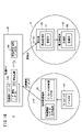
- FIG. 1 is an explanatory diagram schematically showing the overall configuration of a sharing system for electric vehicles according to an embodiment of the present invention.
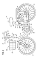
- FIG. 2 is a side view of an electric bicycle, which is an electric vehicle.
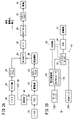
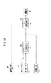
- FIG. 3A is a block diagram showing the flow of driving force of an electric bicycle.
- FIG. 3B is a block diagram showing power wiring between the main battery and mobile battery and the drive source.
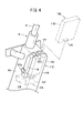
- FIG. 4 is a perspective view showing a second holder that houses the mobile battery.
- FIG. 5 is a flow chart showing how to use the sharing system.
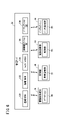
- FIG. 6 is a block diagram showing the configuration of the sharing system.
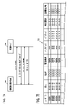
- FIG. 7A is a flowchart showing a processing procedure between an information processing terminal and a management server at the time of user registration.
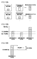
- FIG. 7B is an explanatory diagram exemplifying a registrant database.
- FIG. 8 is a flow chart showing the processing procedure between the information processing terminal and the management server in the use application.
- FIG. 9 is an explanatory diagram illustrating an example of screen information for use application.
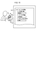
- FIG. 10 is an explanatory diagram illustrating screen information for inputting mobile battery information.
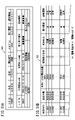
- FIG. 11A is an explanatory diagram illustrating application reception information in which user information and application information are linked.
- FIG. 11B is an explanatory diagram illustrating a mobile database.
- FIG. 12A is a first explanatory diagram illustrating matching between an electric vehicle and a mobile battery.
- FIG. 12B is a second explanatory diagram illustrating matching between the electric vehicle and the mobile battery.
- FIG. 12A is a first explanatory diagram illustrating matching between an electric vehicle and a mobile battery.
- FIG. 12C is a third explanatory diagram illustrating matching between the electric vehicle and the mobile battery.
- FIG. 13 is an explanatory diagram exemplifying the map screen information of the electric vehicle provided by the management server through matching.
- FIG. 14A is an explanatory diagram exemplifying the movable range of the electric vehicle.
- FIG. 14B is an explanatory diagram exemplifying shared battery information displayed when a battery station is selected.
- FIG. 15 is an explanatory diagram illustrating a shared battery database.
- FIG. 16 is a block diagram showing an example of processing for assigning battery identification information to a mobile battery.
- FIG. 17 is a block diagram showing a configuration for performing user authentication when a user borrows an electric vehicle.
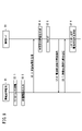
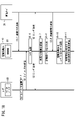
- FIG. 18 is a flow chart showing the processing procedure of the mobile battery, the electric vehicle, and the management server in user authentication.
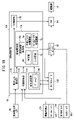
- FIG. 19 is a block diagram showing the internal configuration of the control unit when the user uses the electric vehicle.
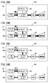
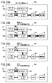
- FIG. 20A is a block diagram showing power supply control when the mobile battery is not connected.
- 20B to 20D are block diagrams showing power supply control when a mobile battery is connected.
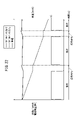
- FIG. 21 is a graph illustrating the output value of the mobile battery and the operation of the main battery with respect to the required power.
- FIG. 22 is a graph exemplifying changes in the remaining battery level of the main battery when the mobile battery is not connected and when the mobile battery is connected.
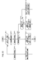
- FIG. 23 is a flowchart exemplifying the control flow of the control unit when using the electric vehicle.
- FIG. 20A is a block diagram showing power supply control when the mobile battery is not connected.
- 20B to 20D are block diagrams showing power supply control when a mobile battery is connected.
- FIG. 21 is
- FIG. 24 is an explanatory diagram showing information communication with the management server when the user uses the electric vehicle.
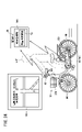
- FIG. 25A is an explanatory diagram illustrating a state in which a movable range is displayed on the map information of the touch panel.
- FIG. 25B is an explanatory diagram exemplifying a low remaining amount notification of the touch panel.
- FIG. 26 is an explanatory diagram illustrating calculation of a plurality of moving routes to a destination.
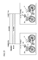
- FIG. 27 is an explanatory diagram exemplifying the detection of the usage period of the electric vehicle and the calculation of the usage fee.
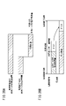
- FIG. 28A is an explanatory diagram exemplifying the calculation of the charge based on the battery usage of the main body battery.
- FIG. 28B is an explanatory diagram exemplifying calculation of another charge using the battery usage of the main body battery.
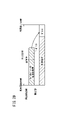
- FIG. 29 is an explanatory diagram exemplifying the calculation of the usage fee using the battery usage of the mobile battery.
- FIG. 30 is a perspective view showing a holding form of the mobile battery according to the first modified example.
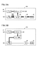
- FIG. 31A is a block diagram showing power supply from the main body battery to the mobile battery according to the second modification.
- FIG. 31B is a block diagram showing power supply from the mobile battery to the main battery according to the third modification.
- FIG. 32 is a block diagram showing another example of the electric vehicle according to one embodiment.
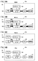
- 33A to 33D are diagrams showing another example of the operation of the electric vehicle according to one embodiment.
- 34A to 34D are diagrams showing another example of the operation of the electric vehicle according to one embodiment.
- An electric vehicle 10 according to one embodiment of the present invention is applied to a sharing system 12, as shown in FIG. Shared among users.
- a sharing system 12 a plurality of electric vehicles 10 are arranged with respect to one or more stations 22 provided in the city by a business operator.
- a user registered in the sharing system 12 applies for use of the electric vehicle 10 , and after applying, goes to an appropriate station 22 to receive the electric vehicle 10 , thereby using the electric vehicle 10 .
- the user After using the electric vehicle 10, the user returns the electric vehicle 10 to the station 22 at the location where it was received or at a location different from the reception location.
- the electric vehicle 10 has a vehicle body 14 and a drive source 16 such as a motor provided on the vehicle body 14 .
- the electric vehicle 10 supplies electric power from one or more batteries 18 to drive the drive source 16, thereby assisting the traveling of the vehicle body 14 or self-propelled.
- Examples of this type of electric vehicle 10 include an electric bicycle 20A, an electric kickboard 20B, an electric wheelchair 20C, and an electric cart 20D.
- the electric vehicle 10 is not limited to this, and can be applied to vehicles (autonomous mobile robots, follow-up mobile robots, care robots, unmanned guided vehicles, etc.) that move in facilities or in the city.
- FIG. 1 illustrates a plurality of types of electric vehicles 10 (electric bicycle 20A, electric scooter 20B, electric wheelchair 20C, and electric cart 20D)
- the sharing system 12 includes at least one type of electric mobility. A service for sharing the body 10 may be used.
- the sharing system 12 is constructed as a client-server type using a network 24 such as the Internet.
- the sharing system 12 includes a user's information processing terminal 26 , a management server 28 , a management machine 30 of the station 22 , and a battery station 34 of the shared battery 32 as components connected to the network 24 .
- the electric vehicle 10 itself has a wireless communication function that can be connected to the network 24, and can be configured to communicate with the management server 28 while the user is using it or waiting at the station 22.
- Examples of the user's information processing terminal 26 include a portable electronic device 36 that the user carries on a daily basis and performs information processing based on the user's operation.
- a smart phone 37 is illustrated as a representative of the electronic device 36 .
- the information processing terminal 26 is not limited to the smart phone 37, and may be a desktop computer, laptop computer, or other portable electronic device 36 (mobile phone, PDA, tablet, wearable computer, etc.).
- the electronic device 36 has a computer including one or more processors, memories, and input/output interfaces (not shown), and is connected to the network 24 so that information can be communicated. Further, the electronic device 36 includes an input/output unit 36a such as a touch panel, a speaker, and a microphone, and also includes a communication module (not shown) capable of close proximity wireless communication with an external device. The user accesses the management server 28 of the sharing system 12 by operating the input/output unit 36a to input/output information about the sharing system 12, search, and the like.
- the management server 28 is installed in the management center 29 of the sharing system 12 provider and used as a host machine for the sharing system 12 .
- the management server 28 manages a plurality of registered users and a plurality of electric vehicles 10 provided.
- the management server 28 is configured as a computer including one or more processors, memories, input/output interfaces, etc. (not shown).
- the management server 28 may be configured by linking a plurality of computers.
- Each station 22 of the electric bicycle 20A, the electric kickboard 20B, the electric wheelchair 20C, and the electric cart 20D is provided in various places in the city (for example, stations, main roads, near commercial facilities, etc.).
- a plurality of electric vehicles 10 of a predetermined type are parked at each station 22 .
- Each station 22 is provided with a plurality of station lock mechanisms 38 corresponding to the number of vehicles to be parked.
- the station lock mechanism 38 locks each of the parked electric vehicles 10 so that they cannot be taken out, and unlocks them so that they can be taken out.
- a management machine 30 provided in each station 22 has a computer (vehicle management unit 31) including one or more processors, memories, and input/output interfaces (not shown) and a communication module, and is an electric vehicle parked at the station 22. Manage 10.
- the management machine 30 controls the operation of each station lock mechanism 38 to set a predetermined electric movable body 10 in a removable state when the electric movable body 10 is rented, and at the same time, the returned electric movable body 10 can be taken out. disabled.
- the management machine 30 acquires mobile body information (mobile body identification information, battery remaining amount of the main body battery 100 described later, etc.) from the parked electric vehicle 10 and automatically sends the acquired mobile body information to the management server 28. send to
- the battery station 34 of the shared battery 32 accommodates a plurality of shared batteries 32 and charges the accommodated shared batteries 32 .
- the battery station 34 is installed, for example, in a facility 33 (commercial facility, store) in the city.
- the battery station 34 has one or more processors, memories, a computer (battery management unit 35) including an input/output interface (not shown), and a communication module, and manages the share battery 32 accommodated in the battery station 34 .
- the battery management unit 35 acquires shared battery information (battery identification information, remaining battery capacity of the shared battery 32 , etc.) from the accommodated shared battery 32 and automatically transmits the acquired shared battery information to the management server 28 .
- the user who applied for the use of the shared battery 32 temporarily uses (carries, discharges, charges) the shared battery 32 by going to an appropriate facility 33 and receiving the shared battery 32 . After using the shared battery 32, the user returns (accommodates) the shared battery 32 to the battery station 34 at the location where it was received or at a location different from the location where it was received.
- the electric bicycle 20A has a vehicle body 14 including a vehicle body frame 40, a handle 42, a saddle 44 and a basket 46, and two wheels (front wheel Wf and rear wheel Wr) attached to the lower portion of the vehicle body 14.
- the vehicle body frame 40 includes a front head pipe 48 , a main frame 50 extending rearward and downward from the head pipe 48 , a seat pipe 52 extending upward from the rear end of the main frame 50 , and a seat pipe 52 extending rearward and downward from the upper portion of the seat pipe 52 .
- a crankshaft 58 is pivotally supported at a connection point between the main frame 50 and the seat pipe 52 (approximately in the middle position in the longitudinal direction of the vehicle body 14).
- a pair of left and right pedals 60 are provided at the extending end of the crankshaft 58 extending from the shaft support portion 40a of the vehicle body frame 40, and the crankshaft 58 rotates as the pair of left and right pedals 60 rotate.
- a one-way clutch 62 (see FIG. 3A) is provided on the shaft support portion 40a of the crankshaft 58, and the rotational force of the crankshaft 58 (the user's stepping force: the force of pedaling the pedal 60) is transmitted via the one-way clutch 62.
- a sprocket 64a is provided. The front sprocket 64 a constitutes a part of a force synthesizing device 64 that synthesizes the rotational force of the crankshaft 58 and the rotational driving force of the drive source 16 .
- the rotation of the front sprocket 64a is transmitted via the chain 66 to the rear sprocket 68 provided on the rear wheel Wr, causing the rear sprocket 68 to rotate.
- the rear sprocket 68 is connected to the rear wheel Wr via a one-way clutch 70 (see FIG. 3A). Therefore, the rear wheel Wr rotates following the rotation of the rear sprocket 68 .
- a pair of left and right second sub-frames 56 are provided with a rear wheel brake (not shown) for braking the rotation of the rear wheel Wr.
- the vehicle body 14 for example, the carrier frame or the rear fender
- a vehicle lock mechanism 72 that restricts rotation of the rear wheel Wr in the locked state and allows rotation of the rear wheel Wr in the unlocked state.
- a seat post 74 having a saddle 44 at its upper end is attached to the seat pipe 52 . Further, the seat pipe 52 is provided with an actuator 76 capable of vertically displacing the seat post 74 based on power supply from the battery 18 .
- the actuator 76 constitutes a position adjusting mechanism that adjusts the height position of the saddle 44 .
- the handle 42 has a pair of left and right grips 82 and a pair of left and right brake levers 84 .
- the front wheel brake is actuated when the right brake lever 84 is operated by the user, and the rear wheel brake is actuated when the left brake lever 84 is operated by the user.
- the driving source 16 of the electric bicycle 20A is, for example, a small motor such as a motor with a brush or a brushless motor, and is provided near the crankshaft 58.
- the rotating shaft of the drive source 16 is connected to a one-way clutch 86, which is gear-connected to a reduction mechanism 88, as shown in FIG. 3A.
- the speed reduction mechanism 88 is connected to an assist sprocket (not shown) of the force synthesizing device 64 , and the rotational force of the assist sprocket (that is, the drive source 16 ) is transmitted to the front sprocket 64 a or the chain 66 .
- An in-hole motor may be applied to the drive source 16 .
- the drive source 16 directly rotates the rear wheel Wr and the crankshaft 58 by a rotor provided on the shaft of the rear wheel Wr and the crankshaft 58 and a stator arranged on the outer periphery of the rotor.
- a drive control device 90 that controls driving of the drive source 16 is provided between the pair of left and right second sub-frames 56 .
- the drive control device 90 includes a junction box 92 to which a plurality of harnesses are connected, a PCU 94 (Power Control Unit) connected to the junction box 92 that converts DC power into three-phase AC power and supplies it to the drive source 16, and a junction A control unit 96 that controls the box 92, the PCU 94, and the like.
- the drive control device 90 receives detection signals from a torque sensor provided near the crankshaft 58 and a rotation sensor provided near the rear wheel Wr (hereinafter collectively referred to as a required power sensor 98 (see FIG. 3A)). , the power supply to the drive source 16 is adjusted.
- the above-described electric bicycle 20A applies a user's pedaling force to a pedal 60, a crankshaft 58, a one-way clutch 62, a force multiplier 64 (front sprocket 64a), a chain 66, a rear sprocket 68, a one-way clutch 70, a rear It is transmitted in order of the wheel Wr. Further, under the control of the drive control device 90, the power of the battery 18 is transmitted from the PCU 94 to the drive source 16 to rotate the drive source 16.
- the rotational force of the drive source 16 is transmitted to the one-way clutch 86, the speed reduction mechanism 88, the force synthesizing device 64 (assist sprocket), the chain 66, the rear sprocket 68, the one-way clutch 70, and the rear wheel Wr in this order.
- the user's pedal operation is assisted by the driving force of the drive source 16, so that the user can comfortably ride the electric bicycle 20A.
- the electric bicycle 20A can use a plurality of batteries 18 as shown in FIGS. 2 and 3B.
- the plurality of batteries 18 includes a main body battery 100 pre-attached to the vehicle body 14 by the operator of the sharing system 12, and a mobile battery 100 carried by the user and detachably attached to the vehicle body 14 when the electric vehicle 10 is used.
- a battery (user battery) 102 .
- the main body battery 100 basically has a larger charging capacity than the mobile battery 102, and is large and heavy, and is replaced or charged by a business operator's replacement operator.
- the main body battery 100 preferably has an output voltage of 20 V or higher and a capacity of 8 Ah or higher, for example, depending on the type of the electric vehicle 10 .
- the main battery 100 is positioned between the seat pipe 52 and the rear wheel Wr when the electric bicycle 20A is mounted, and is fixed in a posture that extends along the seat pipe 52 .
- the main body battery 100 is detachably attached to a first holder 104 provided between the pair of left and right first sub-frames 54 and between the pair of left and right second sub-frames 56 .
- the seat pipe 52 or the first sub-frame 54 is provided with a body-side locking device 106 that locks removal of the body battery 100 from the first holder 104 .
- the first holder 104 is provided with a first holder sensor 108 (voltage sensor, etc.: see FIG. 2) that detects the state of the main battery 100 in order to calculate the remaining battery capacity of the main battery 100 .
- the first holder sensor 108 is connected to the control section 96 and transmits detection signals to the control section 96 .
- the main battery 100 may be configured to automatically transmit the remaining battery power to the control unit 96, the management machine 30, or the management server 28 by providing a function of detecting and calculating the remaining battery power and a communication function. good.
- the mobile battery 102 has a smaller charging capacity than the main battery 100 and is configured to be smaller and lighter than the main battery 100 .
- the capacity of the mobile battery 102 is not particularly limited, for example, a capacity of 2 Ah or more is preferable.
- the mobile battery 102 can use the battery 110 owned by the user to charge the electronic device 36 (smartphone 37: see FIG. 1, tablet, etc.).
- This battery 110 has a power port 120 capable of outputting power on its side peripheral surface.
- the mobile battery 102 may be a battery (not shown) integrally attached to the electronic device 36 for operating the electronic device 36 itself.
- the electronic device 36 used as the mobile battery 102 has a power port 120 capable of outputting the power of the battery of the electronic device 36 to the outside.
- FIG. 4 shows a thin rectangular parallelepiped battery 110, the shape of the mobile battery 102 is not particularly limited as long as it can be held in a second holder 112 described below.
- the mobile battery 102 may apply the shared battery 32 borrowed by the user from the battery station 34 .
- the electric bicycle 20A has a second holder 112 that houses the mobile battery 102 on the rear side of the head pipe 48 (opposite side of the basket 46 that sandwiches the head pipe 48).
- the head pipe 48 is formed to have thickness in the longitudinal direction and the width direction of the vehicle body 14 .
- the second holder 112 has a storage housing 114 integrally connected to the head pipe 48 .
- the storage housing 114 extends along the head pipe 48 from the upper end portion of the head pipe 48 where the steering shaft 78 is exposed to the connection point with the main frame 50 .
- a slit 116 for holding the mobile battery 102 is provided in the housing 114 for storage.
- the slits 116 are formed by continuously opening the upper surface and both width direction side surfaces of the storage housing 114, and various mobile batteries 102 can be inserted from the upper side of the storage housing 114.
- a cushioning member (not shown) that reduces vibrations applied to the mobile battery 102 from the vehicle body 14 may be provided on the inner wall surface forming the slit 116 in the storage housing 114 .
- a connector (connection terminal, mounting terminal) 118 electrically connected to the mobile battery 102 is provided on the inner wall surface (bottom surface).
- the second holder 112 may have a cable (connection cable) connectable to the power port 120 of the mobile battery 102 and a storage hole for storing the cable in the inner wall surface (both not shown).
- a configuration may be adopted in which the cable taken out by the user is connected to the mobile battery 102 and then the mobile battery 102 is inserted into the slit 116 .
- the second holder 112 preferably has a detachment prevention mechanism 122 that prevents the mobile battery 102 from being detached.
- the detachment prevention mechanism 122 includes a side arm 122a that can be adjusted in length to match the size of the mobile battery 102 on the side of the storage housing 114, and a side arm 122a that can be protruded and retracted at an opening above the storage housing 114. and a lock bar 122b.
- the detachment prevention mechanism 122 protrudes the lock bar 122b to lock the mobile battery 102 when it is inserted, and locks under operation of an unlocking input unit (for example, password input, physical key operation, radio signal) not shown. Release.
- an unlocking input unit for example, password input, physical key operation, radio signal
- an information acquisition unit 124 for acquiring information (at least one of identification information, output voltage, charge capacity, remaining battery level, etc.) of the mobile battery 102 is provided inside the second holder 112, an information acquisition unit 124 for acquiring information (at least one of identification information, output voltage, charge capacity, remaining battery level, etc.) of the mobile battery 102 is provided.
- the information acquisition unit 124 is configured by combining one or a plurality of communication modules, voltage sensors, or other sensors, and is communicably connected to the control unit 96 .
- a voltage conversion section 126 is provided that steps up the input voltage input from the mobile battery 102 and steps down the input voltage input from the main battery 100.
- voltage converter 126 is interposed in the power path between mobile battery 102 set in second holder 112 and junction box 92 .
- the voltage conversion section 126 has a DC/DC converter 128 .
- the DC/DC converter 128 may be a bi-directional converter having both boost and step-down functions.
- junction box 92 is connected to each of the main battery 100, the voltage converter 126 (mobile battery 102) and the PCU 94 via electric wiring. Junction box 92 switches power paths and power distribution between main battery 100 and mobile battery 102 under the control of control unit 96 .
- the control unit 96 is configured by a computer having one or more processors, memories, and input/output interfaces.
- the control unit 96 controls power supply to the main battery 100 and the mobile battery 102 by causing the processor to execute a program stored in the memory in accordance with the power-on operation of the operation unit (not shown) of the electric vehicle 10 .
- the control unit 96 also communicates information with the management machine 30 of the station 22 or the management server 28 via a communication module (not shown).
- the electric vehicle 10 is equipped with a positioning system (not shown) such as GNSS, and is configured to periodically observe the current position.
- the controller 96 may be attached to the motor-driven movable body 10, which includes a controller having a communication function, a controller having an authentication function described later, a controller having a lock function, and the like.
- the electric vehicle 10 may also include a touch panel 43 at the center of the handle 42 in the width direction.
- the touch panel 43 has one or more processors, memories, input/output interfaces, and communication modules, and is connected to the management server 28 and the controller 96 of the electric vehicle 10 so that information can be communicated therewith.
- the touch panel 43 is configured to display various information provided from the management server 28 and the control unit 96 and allow the user to input settings for the electric vehicle 10 .
- the user when using the sharing system 12, the user performs user registration (step S1), application for use (step S2), borrowing of the electric vehicle 10 (step S3), use of the electric vehicle 10 (Ste S4), return of the electric vehicle 10 (step S5), and payment of the usage fee (step S6) are sequentially performed.
- the management server 28 comprehensively monitors the state of the user, the state of the electric vehicle 10, the state of the shared battery 32, and the like by managing each step of the usage method.
- the management server 28 As shown in FIG. It has a database 136 (mobile station DB) and a battery station database 138 (battery station DB).
- the registrant DB 130, the mobile DB 132, the shared battery DB 134, the mobile station DB 136, and the battery station DB 138 are linked so as to be able to federate each other. Therefore, when the information in one DB (for example, the remaining battery level of the main body battery 100 of the electric vehicle 10) is updated, the information in the other DB is also updated.
- the management server 28 is configured to enable information communication between the control unit 96 of each electric vehicle 10 of the sharing system 12 and the vehicle management unit 31 of each management machine 30 .
- the management server 28 appropriately collects information from the control unit 96 and information from the vehicle management unit 31, and updates the mobile DB 132 and the mobile station DB 136 as needed.
- the management server 28 is configured to be able to communicate information with the battery management unit 35 of the battery station 34, appropriately collects information on the shared battery 32, and updates the shared battery DB 134 and the battery station DB 138 as needed.
- the information processing terminal 26 of the user accesses the management server 28 to acquire information necessary for using the sharing system 12 from the management server 28 .
- the user accesses the management server 28 from the information processing terminal 26 as shown in FIG. 7A (step S1-1).
- the user downloads and installs the application 140 from the management server 28 to the information processing terminal 26 (step S1-2).
- the application 140 of the information processing terminal 26 facilitates information transmission/reception with the management server 28 .
- the information processing terminal 26 may be configured to be capable of inputting information and searching for information by downloading a dedicated website instead of the application 140 .
- the user opens an input screen for registering with the sharing system 12 on the application 140 or homepage, and inputs the user information necessary for registration.
- User information includes, for example, name, address, telephone number, e-mail address, password, and the like.
- the user After inputting user information on the information processing terminal 26, the user transmits this user information from the information processing terminal 26 to the management server 28 (step S1-3).
- the management server 28 issues user identification information (hereinafter referred to as a user ID) when user registration is accepted along with the reception of user information, and transmits the user ID to the information processing terminal 26 (step S1-4).
- a user ID user identification information
- the user ID may be set by the user himself/herself.
- the management server 28 stores the user information of the new user in the registrant DB 130.
- the user ID and user information (name, address, telephone number, e-mail address, password, etc.) for each user are stored in the registrant DB 130 in a mutually linked state.
- the registrant DB 130 also includes a usage history column for storing, on a user-by-user basis, a usage history when the user used the electric vehicle 10, and an adjustment information column for storing, on a user-by-user basis, adjustment information for adjusting the electric vehicle 10. and
- the usage history includes the number of times of use, the start date and time of use and the end date and time of use in the past, the number and time of extension of use, the number of failures, and the like.
- the user ID is stored in the application 140, and the user ID can be automatically assigned when information is transmitted/received with the management server 28.
- the management server 28 can search for users in the registrant DB 130 based on the user ID and quickly extract the target user.
- the sharing system 12 may be configured to allow the electric vehicle 10 to be used without executing the user registration (assigning a user ID) in FIG. good.
- step S2 see FIG. 5
- step S2-1 a processing flow of application for use will be described with reference to FIG.
- step S2-1 the user activates the application 140 of the information processing terminal 26 (or downloads the home page for applying for use from the management server 28)
- screen information 142 for generating application information includes the type of electric vehicle 10, the start date and time of use, the end date and time of use, the borrowing location (or current location), and the return location.
- the use condition may be configured such that the destination when the electric vehicle 10 is used is input instead of (or together with) the return location.
- the application 140 (or the home page) uses the previously acquired user information address and the user's current location to preferentially provide stations 22 near the user as a borrowing place or return place, and also provides a map of the station 22. Information should be displayed.
- the user After inputting the application information, the user transmits the application information including the user ID and password from the information processing terminal 26 to the management server 28 (step S2-3).
- the management server 28 extracts the user information from the registrant DB 130 based on the user ID, and when determining that the password matches the user information, generates the application acceptance information 144 (step S2-4).
- the management server 28 matches the user who applied for use with the electric vehicle 10 that can be rented based on the application acceptance information 144 (step S2-5). Then, the management server 28 transmits the information of the electric vehicle 10 extracted by the matching to the information processing terminal 26, and provides the information of the electric vehicle 10 to the user who applied (step S2-6). The user selects an electric vehicle 10 to be borrowed by searching and confirming the information provided electric vehicle 10, and transmits this mobile unit selection information to the management server 28 (step S2-7). Thereby, the management server 28 determines the electric vehicle 10 to be rented to the user (step S2-8).
- the sharing system 12 is configured to transmit information on the mobile battery 102 from the user to the management server 28.
- Information on the mobile battery 102 includes battery identification information (battery ID), remaining battery capacity, maximum output power, and the like.
- the sharing system 12 matches the electric vehicle 10 based on the remaining battery level of the mobile battery 102 during the matching (step S2-5).
- the sharing system 12 performs user authentication based on the battery ID when borrowing the electric vehicle 10 (step S3), which will be described later.
- the user when inputting the application information, the user, in addition to the above-mentioned usage start date and time, usage end date and time, borrowing place, and returning place, information of the mobile battery 102 (battery ID, remaining battery capacity, maximum output power, etc.) are entered together.
- a battery ID assigned in advance to the mobile battery 102 can be used.
- the sharing system 12 may be configured to automatically assign a battery ID from the information processing terminal 26 to the mobile battery 102 connected to the information processing terminal 26 .
- the management server 28 may assign battery IDs in the order of the information processing terminal 26 and the mobile battery 102 .
- the management server 28 may extract and store the battery ID of the shared battery 32 itself when the shared battery 32 is borrowed by the user. This eliminates the need for the user to input the battery ID by inputting that the shared battery 32 will be used when applying for use of the electric vehicle 10 .
- the user enters the values at the time of application for use. For example, the user inputs into the information processing terminal 26 the remaining battery level and maximum output power displayed or attached to the mobile battery 102 .
- the information processing terminal 26 and a control circuit (not shown) of the mobile battery 102 perform information communication via USB or the like. information is automatically extracted. This reduces the trouble and mistakes caused by manual input by the user.
- the maximum battery capacity is used as the remaining battery capacity of the mobile battery 102. may be entered.
- the management server 28 When receiving the application information from the information processing terminal 26, the management server 28 extracts the user information of the user who applied from the registrant DB 130, and as shown in FIG. 144 is generated.
- the application reception information 144 includes user ID, name, address, telephone number, email address, usage history, adjustment information, usage start date and time, usage end date and time, borrowing location (or current location), return location (or destination). , battery ID, remaining battery capacity, and maximum output power.
- the management server 28 After generating the application acceptance information 144, the management server 28 performs matching (step S2-5: FIG. 8). In this matching, the management server 28 reads the mobile body DB 132 and the mobile body station DB 136 and extracts the electric mobile body 10 that can be rented based on the application reception information 144 .
- the mobile body DB 132 stores mobile body identification information (mobile body ID), current position, remaining battery capacity of the main body battery 100, specification of the drive source 16, usage information, and usage information for each of the plurality of electric vehicles 10. It stores the situation, past lending history, and failure history.
- the management server 28 periodically communicates with the management machine 30 of the station 22 or the control unit 96 of the electric vehicle 10 to update the current position, remaining battery capacity of the main body battery 100, and the like.
- the mobile station DB 136 stores, for example, the position of the station 22, the mobile ID of the parked electric mobile 10, the remaining battery capacity of the main battery 100, and the operating state of each station lock mechanism 38. I remember.
- the management server 28 extracts the electric mobile body 10 that can be used from the mobile body DB 132 based on the usage conditions included in the application reception information 144 and the battery level and maximum output power of the mobile battery 102. .
- the management server 28 first, based on the type of the electric vehicle 10, the start date and time of use, and the location (or the current location) of the electric vehicle 10 among the usage conditions, the electric vehicle scheduled to be available for rent at or around the location at the start date and time of use. Limit the moving body 10 .
- the management server 28 refers to the maximum output power of the mobile battery 102 and the limited specifications of the drive source 16 of each electric vehicle 10, and ranks the electric vehicles 10 to which the mobile battery 102 is likely to fit. put on.
- the management server 28 ranks the electric vehicles 10 in order of the maximum output power of the mobile battery 102 and the power of the drive source 16 being close to each other. Also, at this time, if there is an electric vehicle 10 that does not match the maximum output power of the mobile battery 102 (such as when the power of the drive source 16 is not reached even if the DC/DC converter 128 is used), the electric vehicle 10 to exclude.
- the management server 28 refers to the remaining battery level of the mobile battery 102 and the remaining battery level of the main battery 100 of each ranked electric vehicle 10 to narrow down the electric vehicles 10 as appropriate. As an example, as shown in FIG. 12A, the management server 28 calculates the battery remaining amount of the main battery 100 and the battery remaining amount of the mobile battery 102 for each of the extracted electric vehicles 10 (electric vehicles A, B, . . . ). The overall remaining battery level (total value) is calculated by adding
- the management server 28 selects the electric vehicle 10 whose calculated total exceeds the recommended lending threshold.
- the recommended lending threshold is an index value that allows the user to use the electric vehicle 10 comfortably (without worrying about charging).
- the recommended lending threshold may be a value that varies based on the usage period (usage start date and time, usage end date and time) included in the application acceptance information 144 .
- the management server 28 determines whether the total value exceeds the lendable threshold.
- the lendable threshold is a value that is predicted to prevent the remaining battery levels of the main battery 100 and mobile battery 102 from becoming zero (not requiring charging in the middle) in the average amount of power usage during the usage period. Therefore, the lendable threshold is set to a value lower than the recommended lending threshold.
- the management server 28 may determine not to select the electric vehicle 10 when the calculated total value significantly exceeds the recommended lending threshold. For example, in FIG. 12C, the management server 28 determines the remaining amount difference obtained by subtracting the recommended lending threshold value from the total value of the electric vehicle C and the remaining amount for determination. The management server 28 does not select the electric vehicle C because the remaining amount difference of the electric vehicle C exceeds the determination remaining amount. This is because the electric vehicle 10 with a large total value can be efficiently operated by the sharing system 12 as a whole if the electric vehicle 10 is lent to another user.
- the management server 28 may be configured to estimate the battery usage based on the usage conditions of the application reception information 144 and select the electric vehicle 10 whose estimated battery usage falls within the total value.
- the amount of battery usage is based on the type of electric vehicle 10 (electric power of the drive source 16, etc.) and the usage period (usage start date and time and usage end date and time) included in the usage conditions. can be estimated from the average power consumption of
- the battery usage is calculated by calculating a movement route (or movement distance) based on the type of the electric vehicle 10 included in the usage conditions, the borrowing place and the return place (or destination), and using this movement route as a predetermined type of electric movement. It can be estimated from the average power consumption when the body 10 moves.
- the management server 28 may also be configured to set the recommended lending threshold and the lendable threshold based on the battery usage.
- the information processing terminal 26 of the user is provided with information on a predetermined type of electric vehicle 10 from the management server 28 , and the input/output unit 36 a of the information processing terminal 26 receives information on the electric vehicle 10 .
- information IV is displayed.
- the information IV of the electric vehicle 10 is written on the map screen information 146 by marking, and the user selects (touches or clicks) the marking to obtain further details of the electric vehicle 10. information is displayed.
- the movable range mr can be obtained by calculating the travelable distance based on the total value calculated for each electric vehicle 10 . In this way, by indicating the movable range mr of each electric vehicle 10 in providing information, the user can select an appropriate electric vehicle 10 according to his or her purpose of use.
- the management server 28 refer to the shared battery DB 134 or the battery station DB 138 and display the location information of the battery station 34 together with the information of the electric vehicle 10 (step S2-6). As a result, the user can compare the movable range mr of the electric vehicle 10 and the battery station 34 to plan the travel.
- the shared battery DB 134 stores the battery ID of each shared battery 32, current position, specifications (output voltage, output power, maximum battery capacity, etc.), remaining battery level (or SOC), usage status, past , etc., is stored.
- the battery station DB 138 stores the installation position, the battery ID of the shared battery 32 housed therein, the remaining battery level (or SOC), and the like.
- the management server 28 displays the information IB of the battery station 34 on the map screen information 146, for example, based on the shared battery DB 134 and the battery station DB 138 (see FIG. 14A). If there is no shared battery 32 in the battery station 34 or if the remaining battery levels of all shared batteries 32 are below a predetermined threshold, the map screen information 146 will show do not display.
- the information of the battery station 34 displayed in the map screen information 146 can display the remaining battery level of each shared battery 32 housed in the battery station 34 .
- the information IB of the battery station 34 when the user clicks the information IB of the battery station 34, a list of each shared battery 32 housed and information indicating the remaining battery capacity of each shared battery 32 are displayed.
- the management server 28 calculates the movement route as detailed information of the electric vehicle 10, and estimates it from the calculated movement route. You may calculate the battery usage to be carried out. As a result, when selecting the electric vehicle 10 , the user can check the movement route and battery usage displayed on the information processing terminal 26 and select an appropriate electric vehicle 10 .
- the user can appropriately select the electric vehicle 10 that the user wants to use on the information processing terminal 26 .
- the management server 28 associates the information of the selected electric vehicle 10 with the application reception information 144, and updates the usage status of the mobile unit DB 132 to the rental schedule. Then, the management server 28 does not extract the electric vehicle 10 scheduled to be rented when there is a use application from another user.
- step S3 the process when the user borrows the electric vehicle 10 (step S3) will be described.
- the sharing system 12 compares the user who applied for the use of the electric vehicle 10 with the electric vehicle 10 actually rented by the user to determine whether the user is a legitimate user. judge.
- the sharing system 12 according to this embodiment performs user authentication using the battery ID of the mobile battery 102 .
- the application information at the time of application for use includes the battery ID of the mobile battery 102 input or obtained by the user.
- the management server 28 Upon receiving the application information, the management server 28 generates the application acceptance information 144 including the battery ID as described above (see FIG. 11A).
- the management server 28 receives the mobile body selection information selected by the user and confirms the electric mobile body 10 to be rented to the user, the management server 28 stores the battery ID included in the application reception information 144 before the user actually rents the electric mobile body 10 . manage up to
- the management server 28 controls the electric vehicle 10 actually used by the user, using the managed battery ID as registration identification information (hereinafter referred to as a registration ID). 96.
- the management server 28 functions as an identification information management unit that registers the registration ID in the electric vehicle 10 .
- the management server 28 transmits the registration ID to the electric vehicle 10 a predetermined time (for example, several minutes to a few hours before) before the start date and time of use of the electric vehicle 10 by the user.
- the sharing system 12 may transmit the registration ID to the electric vehicle 10 via the management machine 30 (this pattern is illustrated in FIG. 16), and via the network 24.
- a configuration in which the registration ID is directly transmitted to the electric vehicle 10 is also possible.
- the registration ID is stored in the management machine 30 itself by passing it through the management machine 30, and can be used for management of the electric vehicle 10 by the management machine 30 as well.
- an authentication unit 150 for performing user authentication is constructed by a processor executing a program (not shown) stored in a memory. .
- the authentication unit 150 stores in memory the registration ID transmitted from the management server 28 before the mobile battery 102 is attached. It is preferable that the electric vehicle 10 automatically maintains the locked state by the vehicle lock mechanism 72 (see FIG. 2) when the registration ID is not transmitted. Similarly, it is preferable that the management machine 30 automatically continues the lock of the station lock mechanism 38 in a state in which the registration ID is not transmitted.
- the authentication unit 150 acquires the battery ID from the mobile battery 102 via the information acquisition unit 124 when the mobile battery 102 owned by the user is attached to the second holder 112 of the electric vehicle 10 . Upon acquiring the battery ID, authentication unit 150 performs user authentication by comparing the battery ID with the registered ID held. That is, in user authentication, authentication unit 150 determines whether the battery ID and the registered ID match or do not match. Then, when the IDs match, the user of the electric vehicle 10 is authenticated (hereinafter, the state of user authentication is referred to as user confirmation). It is preferable that the authentication unit 150 continues to confirm continuous use of the electric vehicle 10 by the user by periodically performing user authentication even after the user is once confirmed.
- the control unit 96 shifts the electric vehicle 10 from the travel restricted state to the travel permitted state. Therefore, in addition to the authentication unit 150, the control unit 96 includes a vehicle lock control unit 152, a power supply control unit 154, an adjustment control unit 156, a detachment prevention mechanism control unit 158, a notification unit 160, a usage measurement unit 162, and the like. Built.
- the vehicle lock control unit 152 is a functional unit that controls the vehicle lock mechanism 72 and is configured to automatically operate based on user authentication by the authentication unit 150 .
- the electric vehicle 10 is in a travel restricted state by being locked by the vehicle lock mechanism 72 until the user is confirmed.
- the vehicle lock control unit 152 unlocks the vehicle lock mechanism 72 based on the user's determination. As a result, the electric vehicle 10 transitions from the travel restricted state to the travel permitted state.
- the electric vehicle 10 can be put into a travel restricted state in which the drive source 16 is not driven by prohibiting the power supply from the main battery 100 and the mobile battery 102 to the drive source 16 by the power supply control unit 154 until the user is confirmed. It's becoming When the user is confirmed, the power supply control unit 154 supplies power from the main battery 100 and the mobile battery 102 to the driving source 16, thereby transitioning to the driving allowable state in which the driving source 16 is driven.
- the vehicle management unit 31 of the management machine 30 when the vehicle management unit 31 of the management machine 30 is in a state where the electric vehicle 10 cannot be taken out by the station lock mechanism 38, the vehicle management unit 31 unlocks the electric movable body 10 based on the reception of the user confirmation signal from the control unit 96, The moving body 10 is brought into a takeout ready state.
- the adjustment control unit 156 of the control unit 96 accesses the management server 28 based on the user confirmation and acquires the adjustment information of the user confirmed from the management server 28 .
- the adjustment information is information for adjusting the electric vehicle 10 for each user based on the user's preference, physique, etc., and is sent at the time of user registration or at the time of application for use of the electric vehicle 10. It is managed by the DB 130 (see FIG. 7B). That is, the management server 28 constitutes an adjustment information storage unit that stores adjustment information.
- the adjustment information of the electric bicycle 20A includes the height of the saddle 44, the gear speed, and the like.
- the adjustment information of the electric scooter 20B includes the height of the handle and the like.
- the adjustment information of the electric wheelchair 20C and the electric cart 20D includes seat height, mirror angle, and the like.
- the adjustment information may be stored in the management server 28 by transmitting to the management server 28 the content of adjustment (adjustment data) actually made when the user gets on the vehicle by the control unit 96 of the electric vehicle 10 .
- the adjustment control unit 156 adjusts the electric vehicle 10 based on the adjustment information. For example, when the electric vehicle 10 is an electric bicycle 20A and the adjustment information includes the height of the saddle 44, the adjustment control unit 156 drives the actuator 76 to displace the seat post 74, thereby adjusting the adjustment information. Adjust the height of the saddle 44 according to the adjustment information.
- the detachment prevention mechanism control unit 158 of the control unit 96 operates the detachment prevention mechanism 122 to lock the mobile battery 102 based on the user's determination.
- the electric vehicle 10 can prevent the mobile battery 102 from being stolen when, for example, the user temporarily leaves the electric vehicle 10 during use by the user.
- the vehicle lock control unit 152 and the power supply control unit 154 continue the travel restriction state (locking and power supply prohibition). This prevents the sharing system 12 from using the electric vehicle 10 by a person other than the authorized user.
- the vehicle management unit 31 of the management device 30 does not receive the user confirmation from the control unit 96 of the electric vehicle 10. continue the state. As a result, it is possible to prevent the electric vehicle 10 from being taken out of the station 22 .
- the notification unit 160 of the control unit 96 transmits user uncertainty (user authentication failure) due to the battery ID to the management server 28, and the management server 28 transmits a notification of user uncertainty to the information processing terminal 26 of the user.
- the user who receives the notification can smoothly recognize that the mobile battery 102 connected to the electric vehicle 10 is different from the one registered at the time of application.
- the usage measurement unit 162 of the control unit 96 measures the period of usage of the electric vehicle 10 by the user when the user is confirmed with the attachment of the mobile battery 102 .
- the station 22 where the electric vehicle 10 is rented to the user may be different from the station 22 where the user returns the electric vehicle 10, and it is difficult for the station 22 to measure the usage period. be.
- the processing flow of the sharing system 12 when the user borrows the electric vehicle 10 (step S3 in FIG. 5) will be described below with reference to FIG.
- the management server 28 manages the battery ID, which is transmitted when the user applies for use, in a state of being associated with the electric vehicle 10 that the user plans to rent.
- the management server 28 measures the date and time, and transmits the registration ID to the electric vehicle 10 before the user starts using the electric vehicle 10 (step S3-1). Accordingly, the control unit 96 of the electric vehicle 10 waits while receiving the registration ID and storing it in the memory.
- the user carrying the mobile battery 102, goes to the station 22 where the target electric vehicle 10 is parked, and attaches the mobile battery 102 to the second holder 112 of the electric vehicle 10 (step S3-2).
- the information acquisition unit 124 of the electric vehicle 10 automatically acquires the battery ID from the mobile battery 102, and the control unit 96 receives this battery ID (step S3-3).
- the authentication unit 150 of the control unit 96 performs user authentication by comparing the acquired battery ID with the stored registration ID (step S3-4). In user authentication, if the battery ID and the registration ID match, it is determined that the user who is the user of the electric vehicle 10 is confirmed. As a result, the control unit 96 transmits the user confirmation information to the control circuit of the mobile battery 102 (step S3-5) and to the management machine 30 and the management server 28 (step S3-6).
- the vehicle lock control unit 152 switches the vehicle lock mechanism 72 from locked to unlocked (step S3-7). Also, the power supply control unit 154 of the control unit 96 enables power supply from the main battery 100 and the mobile battery 102 to the drive source 16 (step S3-8). Further, the control unit 96 receives adjustment information from the management server 28 that transmitted the user confirmation (step S3-9). The adjustment control unit 156 of the control unit 96 adjusts the electric vehicle 10 according to the user based on this adjustment information (step S3-10).
- the usage measurement unit 162 of the control unit 96 measures the date and time when the user is first confirmed, determines the usage start date and time, and starts measuring the usage period (step S3-11). As described above, user authentication is performed when the mobile battery 102 is attached, and subsequent control is appropriately performed, so that the user can use the electric vehicle 10 comfortably.
- step S4 the process when the user uses the electric vehicle 10 (step S4) will be described.
- the power supply control unit 154 of the control unit 96 appropriately distributes the power of the main battery 100 and the power of the mobile battery 102 . Therefore, as shown in FIG. 19, within the power supply control unit 154, functional blocks consisting of a required power calculation unit 170, a capacity acquisition unit 172, a boost setting unit 174, a power distribution management unit 176, and a PCU control unit 178 are constructed. .
- the required power calculation unit 170 continuously calculates the required power to be supplied to the drive source 16 based on the detection signal of the required power sensor 98 (torque sensor, rotation sensor), and distributes the calculated required power to the power distribution management unit 176 and the PCU. Output to the control unit 178 .
- the required electric power calculation unit 170 estimates the driving situation based on the reaction force of the pedal 60 applied to the crankshaft 58 detected by the torque sensor and the rotation speed detected by the rotation sensor, and assists according to the driving situation. Calculate the required power as a quantity.
- the capacity acquisition unit 172 calculates the remaining battery level of the main body battery 100 by a well-known calculation method. Also, the capacity acquisition unit 172 calculates or acquires the remaining battery level of the mobile battery 102 based on the information (remaining battery level, output voltage) of the information acquiring part 124 of the second holder 112 . The capacity acquisition unit 172 stores the acquired remaining battery level of the main body battery 100 and the acquired remaining battery level of the mobile battery 102 in a memory, and transmits them to the power distribution management unit 176 .
- the boost setting unit 174 refers to the data map 180 stored in advance to determine the voltage of the DC/DC converter 128 between the input voltage input from the mobile battery 102 and the output voltage output to the drive source 16 (PCU 94). Set the boost amount.
- the boost amount corresponds to, for example, the switching time of a switching circuit (not shown) of the DC/DC converter 128 .
- the mobile battery 102 may include a voltage conversion unit 126 (DC/DC converter) and a control circuit (not shown) having a boost setting unit 174 so that the output power boosted by the mobile battery 102 can be supplied to the outside.
- the boost setting unit 174 acquires information (input voltage, input power, capacity, etc.) of the mobile battery 102 when the mobile battery 102 is held in the second holder 112 .
- the boost setting unit 174 recognizes the specification of the drive source 16 in advance, extracts an appropriate boost amount from the data map 180 based on the acquired information of the mobile battery 102 and the specification of the drive source 16, and sets the extracted boost amount.
- a switching control unit (not shown) of the DC/DC converter 128 boosts the voltage of the mobile battery 102 to the set boost amount by switching the switch circuit based on the transmitted boost amount.
- the data map 180 has specifications for a plurality of types of drive sources 16, so that the DC/DC converter 128 can be easily installed in various types of electric vehicles 10. That is, by referring to the data map 180, the control unit 96 can boost the voltage in the DC/DC converter 128 in accordance with the drive source 16 of the electric vehicle 10 to which it is applied. As a result, the workload of setting the boost amount for each drive source 16 of the electric vehicle 10 is reduced.
- the power distribution management unit 176 When the power distribution management unit 176 receives the requested power, the remaining battery power of the main battery 100, the remaining battery power of the mobile battery 102, and the boost amount of the mobile battery 102, the power distribution management unit 176 controls the power supply of the power of the main battery 100 and the power of the mobile battery 102. conduct.
- the power distribution management unit 176 controls the operation of the junction box 92 so that the control contents shown in FIGS.
- FIG. 20A shows power supply control when the mobile battery 102 is not connected.
- the power distribution management unit 176 supplies the power of the main body battery 100 to the junction box 92, the PCU 94, and the drive source 16 in this order by switching the inside of the junction box 92 as appropriate.
- the drive source 16 is driven only by the power of the main battery 100 .
- FIGS. 20B to 20D show power supply control when the mobile battery 102 is connected.
- the power distribution management unit 176 divides the power of the main battery 100 and the power of the mobile battery 102 into are joined in the junction box 92 and supplied to the drive source 16 .
- the power distribution management unit 176 simultaneously supplies the power of the main battery 100 and the power of the mobile battery 102 to the drive source 16 .
- the power distribution management unit 176 stops power supply from the main battery 100 when the requested power is greater than zero and equal to or less than a predetermined value PD (in the case of a low output request). Thereby, the electric power of the mobile battery 102 is supplied to the DC/DC converter 128, the junction box 92, the PCU 94, and the driving source 16 in this order. Therefore, the drive source 16 is driven only by the power of the mobile battery 102 .
- the power distribution management unit 176 preferably distributes the power of the mobile battery 102 appropriately according to the remaining battery capacity of the main battery 100, the remaining battery capacity of the mobile battery 102, and the requested power. .
- the power distribution management unit 176 supplies power from the mobile battery 102 to the main battery 100 via the junction box 92 (in FIG. pattern).
- the main battery charging threshold Tm may be set to a value equal to or less than the predetermined value PD.
- the power distribution management unit 176 determines that the vehicle body 14 is in a stopped state, power off.
- the power distribution management unit 176 charges the main battery 100 by supplying power from the mobile battery 102 to the DC/DC converter 128, the junction box 92, and the main battery 100 in this order.
- the power distribution management unit 176 acquires the remaining battery level of the main battery 100, and when the main battery 100 is near full charge (for example, the SOC is 90% or more), the mobile battery 102 Power supply to main battery 100 may be stopped. At this time, the power distribution management unit 176 reduces the power output value of the mobile battery 102 . As a result, overcharging of the main battery 100 can be suppressed, and power consumption of the mobile battery 102 can be suppressed.
- the power distribution management unit 176 controls the junction box 92 and the DC/DC converter 128 so as to keep the power output from the mobile battery 102 at a constant output value. is preferred. As shown in FIG. 21, the power distribution management unit 176 controls, for example, the predetermined value PD and the output value of the mobile battery 102 to match. and Therefore, the main battery 100 is the only battery 18 whose output value (or input value) changes according to the required power.
- the power distribution management unit 176 changes the power of the main body battery 100 according to the required power without changing the output value of the mobile battery 102. .
- the power distribution management unit 176 directs power to both the drive source 16 and the main battery 100 by not changing the output value of the mobile battery 102 . In other words, the power distribution management unit 176 supplies from the mobile battery 102 to the main battery 100 the difference in power obtained by subtracting the required power from the output value.
- the output value of the mobile battery 102 is appropriately set by the power distribution management unit 176 according to the remaining battery level of the main battery 100 .
- the output value of the mobile battery 102 is set to a small value. I can give you something to do.
- the electric vehicle 10 preferentially supplies electric power from the mobile battery 102, thereby sufficiently suppressing a decrease in the remaining battery level of the main battery 100.
- change over time in the remaining battery power of the main battery 100 when using a mobile battery 102 that outputs a constant output value of 30 W and change over time in the remaining battery power of the main battery 100 when the mobile battery 102 is not used.
- FIG. 22 illustrates a pattern in which the electric bicycle 20A travels 3 km on a flat road at a vehicle speed of 15 km/h and waits at a signal twice on the way.
- the remaining battery level of the main battery 100 decreases at a substantially constant rate of decrease while the electric bicycle 20A is running. Then, when the electric bicycle 20A stops, the remaining battery level of the main body battery 100 does not decrease and stays the same. Therefore, the remaining battery level of the main battery 100 is greatly reduced after traveling 3 km.
- the remaining battery level of the main battery 100 is substantially constant while the electric vehicle is running, and the rate of decrease is more moderate than when the mobile battery 102 is not used. decreases with Further, when the electric bicycle 20A stops, power is supplied from the mobile battery 102 to the main battery 100, so that the remaining battery capacity of the main battery 100 increases. As a result, even after traveling 3 km, the remaining battery level of the main battery 100 remains almost unchanged. In other words, by applying the mobile battery 102 to the electric vehicle 10, it is possible to sufficiently suppress the chance that the remaining battery level of the main body battery 100 drops significantly.
- the power distribution management unit 176 may set the content of control according to the remaining battery level of the mobile battery 102 .
- the power distribution management unit 176 has a stop threshold Ts corresponding to the remaining battery level of the mobile battery 102 .
- the power distribution management unit 176 supplies power from the mobile battery 102 to the drive source 16 or the main body battery 100 when the remaining battery level of the mobile battery 102 is greater than the stop threshold Ts.
- the power distribution management unit 176 stops the power supply of the mobile battery 102 when the remaining battery level of the mobile battery 102 is equal to or less than the stop threshold Ts.
- the power supply of the mobile battery 102 is stopped, only the power of the main body battery 100 is supplied to the drive source 16 as shown in FIG. 20A. This avoids using the battery of the mobile battery 102 more than necessary.
- the power distribution management unit 176 preferably has a usage content setting unit 182 that allows the user to set the battery usage of the mobile battery 102 .
- the usage content setting unit 182 can communicate with the user's smartphone 37 (the application 140 of the sharing system 12 ) via the communication module and change the stop threshold Ts based on an instruction from the smartphone 37 .
- the usage content setting unit 182 may be configured to be able to set the output value of the mobile battery 102, etc., in addition to the stop threshold value Ts.
- the PCU control section 178 of the control section 96 controls the PCU 94 based on the requested power received from the requested power calculation section 170 .
- the power distribution management unit 176 controls the junction box 92 on the upstream side of the PCU 94 so that necessary power can be supplied to the PCU 94 . Therefore, the PCU control unit 178 can appropriately convert DC power into AC power in the PCU 94 and output the AC power to the drive source 16 according to the range of required power from high output to low output.
- control unit 96 controls driving of the drive source 16 when activated based on the user's power-on operation.
- the power supply control unit 154 of the control unit 96 determines whether or not the mobile battery 102 is connected to the second holder 112 (step S4-1). For example, the power supply control unit 154 determines connection of the mobile battery 102 based on a signal transmitted from the information acquisition unit 124 . If the mobile battery 102 is not connected (step S4-1: NO), the process proceeds to step S4-2. If the mobile battery 102 is connected (step S4-1: YES), step S4 is performed. Go to -4.
- step S4-2 the power supply control unit 154 calculates the required power based on the detection signal of the required power sensor 98. Further, the power supply control unit 154 controls the junction box 92 and the PCU 94 to supply the power of the main body battery 100 to the drive source 16 (step S4-3). As a result, the electric vehicle 10 can run using the power of the main battery 100 .
- step S4-4 the power supply control unit 154 acquires the input voltage of the mobile battery 102 from the information acquisition unit 124 of the second holder 112, refers to the data map 180, and refers to the DC/DC converter 128 based on the input voltage. Set the amount of boost for .
- the power supply control unit 154 calculates the required power based on the detection signal of the required power sensor 98 (step S4-5). Furthermore, the power supply control unit 154 determines the content of control based on the calculated required power. For example, the power supply control unit 154 determines whether or not the requested power is zero (step S4-6). If the requested power is zero (step S4-6: YES), the requested power is certainly below the main battery charge threshold Tm. Therefore, the power supply control unit 154 switches the junction box 92 to stop power supply to the main battery 100, and supplies power from the mobile battery 102 to the main battery 100 (step S4-7). On the other hand, if the required power is equal to or greater than zero (step S4-6: NO), the process proceeds to step S4-8.
- step S4-8 the power supply control unit 154 determines whether or not the required power is equal to or less than a predetermined value PD (a value dividing high output and low output). Then, if the required power is equal to or less than the predetermined value PD (step S4-8: YES), power supply from the main battery 100 is stopped and power from the mobile battery 102 is supplied to the driving source 16 (step S4-9). . At this time, if the required power is lower than the main battery charge threshold Tm, the power supply control unit 154 charges the main battery 100 by supplying surplus electric power of the mobile battery 102 that is not supplied to the drive source 16 to the main battery 100. (see also FIG. 20C).
- a predetermined value PD a value dividing high output and low output
- step S4-8 NO
- the junction box 92 is switched to supply the power of the main battery 100 and the power of the mobile battery 102 simultaneously to the driving source 16 (step S4- 10).
- the electric vehicle 10 can travel while reducing the amount of power used by the main battery 100 .
- the sharing system 12 performs several processes by monitoring the remaining battery capacity of the main battery 100 and the remaining battery capacity of the mobile battery 102 for the electric vehicle 10 in use.
- a usage management unit 190 is formed inside the management server 28 .
- the usage management unit 190 communicates with the control unit 96 of the electric vehicle 10 used by the user to obtain the current position of the electric vehicle 10, the remaining battery level of the main body battery 100, and the battery level of the mobile battery 102. Get remaining amount.
- FIG. 24 shows a state in which communication is performed while the electric vehicle 10 is running. good too.
- the usage management unit 190 monitors the remaining battery level of the entire electric vehicle 10 by calculating the total value of the remaining battery level of the main battery 100 and the remaining battery level of the mobile battery 102 .
- the sharing system 12 may transmit the total value calculated by the usage management unit 190 to the touch panel 43 provided on the electric vehicle 10 .
- the touch panel 43 can allow the user to recognize the remaining battery level of the entire battery 18 of the electric vehicle 10 .
- the touch panel 43 preferably has a function of measuring the current position and a navigation function, and is configured to display the map information 192, the own vehicle X, and the moving route.
- the usage management unit 190 may calculate a moving route based on the usage conditions (return place, destination) of the user's application reception information 144 and provide the moving route to the touch panel 43 . Note that the usage manager 190 may be provided in the touch panel 43 .
- the touch panel 43 may display the movable range mr of the electric vehicle 10 estimated from the acquired total value in the upper layer of the map information 192 . Thereby, the user can easily recognize the movable range mr based on the remaining battery level of the electric vehicle 10 as a whole.
- the touch panel 43 may be configured to display the movable range mr of the remaining battery power of the main battery 100 and the movable range mr of the remaining battery power of the mobile battery 102, respectively.
- the usage management unit 190 has a remaining amount determination threshold value Tp for monitoring the decrease in the remaining battery amount of the battery 18, as shown in FIG.
- the usage management unit 190 compares the total value (or the remaining battery level of the main battery 100 alone, or the remaining battery level of the mobile battery 102 alone) with the remaining amount determination threshold Tp, and determines that the total value is equal to or less than the remaining amount determination threshold Tp. determine whether or not
- the touch panel 43 displays a notice 194 of low remaining capacity as shown in FIG. 25B, for example, based on the reception of the low remaining capacity information.
- the usage management unit 190 may refer to the battery station DB 138 based on the current position of the electric vehicle 10 in use and provide information IB of the battery stations 34 near the current position of the electric vehicle 10. Good (see also Figure 25A).
- the usage management unit 190 may refer to the shared battery DB 134 and provide information on the shared battery 32 that has a sufficient remaining battery level and is available for rent. At this time, the usage management unit 190 calculates the amount of power usage based on the usage conditions of the user's application reception information 144, extracts only the shared battery 32 having a remaining battery level exceeding the amount of power usage, and provides the information. is preferred.
- the management server 28 transmits the battery ID of the shared battery 32 to the authentication unit 150 as a registration ID for user authentication, thereby stably performing user authentication.
- the usage management unit 190 also transmits information on the rentable shared battery 32 or battery station 34, especially when transmitting the above-described low remaining amount information.
- the touch panel 43 displays the location of the share battery 32 together with the low remaining amount notification 194, so that the user can take measures such as borrowing the share battery 32 based on this information.
- the usage management unit 190 may compare the remaining battery level of the electric vehicle 10 with the battery usage based on the usage conditions of the application acceptance information 144 and change the assist mode of the electric vehicle 10 .
- the assist mode includes a power mode in which the power of the battery 18 is used at full power while driving, a normal mode in which the power of the battery 18 is used according to the necessary conditions during driving, a power saving mode in which the power consumption of the battery 18 is reduced, and the like. It is set in multiple stages as follows. As an example, in the power saving mode, power supply from the battery 18 is stopped on a flat road or the like, and power is supplied from the battery 18 only when the route gradient (torque) is large.
- the usage management unit 190 calculates the moving route or moving distance of the electric vehicle 10 based on the usage conditions of the application acceptance information 144, and refers to the stored map information (not shown) to include in the moving route. Recognize the slope of the route. Further, the usage management unit 190 calculates the battery usage in consideration of the travel route, travel distance, route gradient, and the like. Then, the usage management unit 190 transmits an instruction to the control unit 96 to run in the power mode or the normal mode when the battery remaining amount of the electric vehicle 10 is larger than the calculated battery usage amount. As a result, the power supply control unit 154 of the control unit 96 performs control to supply sufficient power from the battery 18 to the drive source 16 in accordance with the required power, causing the user of the electric vehicle 10 to feel discomfort (insufficient assistance). opportunities).
- the control unit 96 performs control to suppress power consumption of the battery 18 based on the instructed power saving mode. As a result, when the user returns the electric vehicle 10, it is possible to prevent the remaining power level of the battery 18 from reaching zero.
- the control unit 96 can perform necessary information communication with the management machine 30 or the management server 28 according to the remaining battery level.
- the usage management unit 190 calculates a plurality of travel routes R from the usage conditions, calculates the battery usage for each travel route R, It is also possible to provide information on the route with the least battery usage among the plurality of routes. By displaying this route information on the map information 192 on the touch panel 43, the user who recognizes this route information can follow the moving route R with reduced power consumption.
- FIG. 26 shows an example of presenting a plurality of movement routes R such as a detour route with low energy Rl, a shortest route with high energy Rh, and another route (medium energy route Rm). showing.
- the usage management unit 190 (or the control unit 96) sets the assist mode to the normal mode when the user travels along the low-energy route Rl, and sets the power-saving mode to the power-saving mode when the user travels along the high-energy route Rh. You may perform control, such as setting to .
- step S5 the process when the user returns the electric vehicle 10 (step S5) and the process of paying the fee (step S6) will be described.
- the user who has used the electric vehicle 10 returns the electric vehicle 10 to the return location (station 22) specified at the time of application for use. Note that the user may return the electric vehicle 10 to a station 22 different from the return location specified in the application acceptance information 144 .
- control unit 96 performs user authentication (user confirmation) based on the battery ID, user confirmation is canceled when the mobile battery 102 is disconnected.
- the control unit 96 may determine the usage end date and time based on the parking of the station 22 and the timing of canceling the user confirmation.
- the usage measurement unit 162 of the control unit 96 recognizes the usage start date and time of the electric vehicle 10 based on the user confirmation, and measures the usage period from that point.
- the usage measurement unit 162 recognizes the usage end date and time of the electric vehicle 10 based on the removal of the mobile battery 102 from the second holder 112 (cancellation of user determination), and terminates usage period measurement at that point. do.
- the usage measurement unit 162 can easily calculate the usage period of the electric vehicle 10 of the user and transmit the calculated usage period to the management server 28 and the management machine 30 .
- the management server 28 is provided with a calculation unit 196 that calculates the usage fee for the electric vehicle 10 based on the usage period measured by the usage measurement unit 162 (see FIG. 17).
- the calculation unit 196 of the management server 28 calculates the usage fee according to the received usage period of the user, and charges the usage fee to the user.
- the sharing system 12 may be configured to be able to use points related to other services, etc., and the calculation unit 196 may calculate points according to the period of use. Further, the sharing system 12 may have a configuration in which the management machine 30 includes the calculation unit 196 and the usage fee for the electric vehicle 10 is settled in the management machine 30 .
- the sharing system 12 may be configured to calculate the usage fee based on the amount of battery usage of the main battery 100 .
- the usage measurement unit 162 recognizes the start of usage of the electric vehicle 10 based on the user confirmation, and measures and stores the remaining battery level of the main battery 100 at that time. Furthermore, the usage measurement unit 162 recognizes the end of usage of the electric vehicle 10 based on the removal of the mobile battery 102 from the second holder 112, and measures and stores the remaining battery level of the main battery 100 at that time. do. The usage measurement unit 162 then calculates the difference between the remaining battery capacity of the main battery 100 at the start of use and the remaining battery capacity of the main battery 100 at the end of use. As a result, the management server 28 and the calculation unit 196 of the management machine 30 can calculate a charge according to the calculated difference in the remaining battery level of the main body battery 100 and charge the user.
- the calculator 196 When reflecting the battery usage of the main body battery 100 in the usage fee, the basic usage fee calculated based on the usage period and points according to the battery usage of the main body battery 100 are calculated, and the usage fee is calculated. You may adopt the calculation method of subtracting points from.
- the calculator 196 has a battery usage reference value corresponding to the battery usage of the main body battery 100, and subtracts the battery usage from the reference value.
- the calculation unit 196 can calculate a high point and greatly discount the usage fee when the main battery 100 is low in battery usage. Further, the calculation unit 196 can calculate a low point when the battery usage amount of the main body battery 100 is large, so that the usage fee can be discounted or increased.
- the sharing system 12 may be configured to measure the power consumption of the mobile battery 102 during the period of use of the electric vehicle 10 and reflect it in the usage fee.
- the usage measurement unit 162 measures the remaining battery level of the mobile battery 102 at the start of usage of the electric vehicle 10 based on the user confirmation, A difference from the remaining battery level of the battery 102 is calculated.
- the calculation unit 196 calculates a low usage fee when the battery usage of the mobile battery 102 is high, and calculates a high usage fee when the battery usage of the mobile battery 102 is low.
- the calculation unit 196 calculates a high point when the battery usage of the mobile battery 102 is large, and calculates a low point when the battery usage of the mobile battery 102 is low. As a result, the calculation unit 196 can calculate a high point and greatly discount the usage fee when the battery usage amount of the mobile battery 102 is large. Further, the calculation unit 196 can calculate a low point when the battery usage of the mobile battery 102 is small to discount or increase the usage fee.
- the calculation unit 196 may of course calculate the usage fee by comprehensively converting the usage period, the amount of power used by the main battery 100, and the amount of power used by the mobile battery 102.
- the sharing system 12 may be configured such that the user directly pays the fee for using the electric vehicle 10 to the management machine 30 .
- the sharing system 12 may include various forms of temporary use, such as a long-term lease of the electric vehicle 10 to the user and a short-term rental of the electric vehicle 10 to the user.
- the sharing system 12 may be configured such that one electric vehicle 10 is shared by a plurality of users. Further, for example, the electric vehicle 10 may not only be applied to the sharing system 12, but may also be owned by an individual. The electric vehicle 10 may be configured to apply only the mobile battery 102 as one or more batteries 18 .
- the electric vehicle 10 other than the electric bicycle 20A may also have the second holder 112 for fixing the mobile battery 102 at an appropriate position.
- the electric scooter 20B may have a configuration in which the second holder 112 is provided in the swelling portion 204 that connects the handle shaft 200 and the floor plate portion 202 .
- the electric wheelchair 20C and the electric cart 20D can be configured to have the second holder 112 in the armrest portion 206 provided adjacent to the seat on which the user sits.
- the electric vehicle 10 may have a second holder 112 that holds the mobile battery 102 in the handle 42 (the frame near the steering shaft 78).
- the second holder 112 fixes the smartphone 37 so that the input/output unit 36 a of the smartphone 37 faces the user sitting on the saddle 44 .
- the mobile battery 102 (smartphone 37) can supply power to the drive source 16 and the main body battery 100 and display various information in the same manner as the touch panel 43 when the electric vehicle 10 is used. can.
- the electric vehicle 10 may be configured to charge the power of the main battery 100 to the mobile battery 102 when the power of the mobile battery 102 is low.
- the control unit 96 has a mobile battery charge threshold Tu (charge threshold: see the dotted line in FIG. 19) in the power distribution management unit 176, and when the remaining battery level of the mobile battery 102 becomes equal to or less than the mobile battery charge threshold Tu, The power of the main body battery 100 is supplied to the mobile battery 102 .
- the mobile battery charge threshold Tu is preferably set to be smaller than the stop threshold Ts, or may be configured to be settable by the user via the usage setting section 182 .
- the power of the main body battery 100 is converted to a voltage suitable for charging the mobile battery 102 via the step-down DC/DC converter 210 (voltage conversion unit 126).
- the power distribution management unit 176 monitors the required power to the drive source 16, and when the required power is low (during stoppage or low output), the main battery Power is directed from 100 to mobile battery 102 .
- the electric vehicle 10 can charge the mobile battery 102 while preventing insufficient power supply to the drive source 16 .
- the electric vehicle 10 may be configured to use the power of the mobile battery 102 only for charging the main battery 100 and not to supply power to the drive source 16 .
- a DC/DC converter 128 and a chopper circuit 212 are provided between the main battery 100 and the mobile battery 102 .
- the control unit 96 cuts off the power supply of the mobile battery 102 by the chopper circuit 212 while the electric vehicle 10 is running.
- the control unit 96 recognizes that the electric vehicle 10 is not moving (required electric power is zero) and stops supplying power from the main battery 100 to the drive source 16
- the chopper circuit 212 is cut off and the mobile battery is turned off. 102 is supplied to the main body battery 100 . In this way, even if the mobile battery 102 only charges the main battery 100, it is possible to prevent the remaining battery level of the main battery 100 from decreasing.
- the sharing system 12 extracts an appropriate type of electric vehicle 10 based on the information of the mobile battery 102 in the management server 28, may be proposed to For example, the management server 28 extracts the electric scooter 20B with high power consumption when the remaining battery level of the mobile battery 102 is high, and selects the electric bicycle 20A with low power consumption when the remaining battery level of the mobile battery 102 is low. Extract. This allows the user to use an appropriate electric vehicle 10 according to the mobile battery 102 .
- the authentication unit 150 that performs user authentication is not limited to the configuration provided in the electric vehicle 10 , and may be provided in the management machine 30 of each station 22 or the management server 28 .
- the control unit 96 of the electric vehicle 10 acquires the battery ID from the mobile battery 102 attached to the second holder 112, and uses the battery ID as Send to the management server 28 .
- the management server 28 can compare the transmitted battery ID with the registration ID to determine whether the user is a legitimate user who has applied for use of the electric vehicle 10 .
- the usage measurement unit 162 of the control unit 96 is not limited to the configuration provided in the electric vehicle 10 , and may be provided in the management machine 30 of each station 22 or the management server 28 .
- the sharing system 12 allows the user to use the electric vehicle 10 by carrying the mobile battery 102 to the station 22 and connecting the mobile battery 102 to the electric vehicle 10 on standby without applying for use. It may be possible.
- the control unit 96 of the electric vehicle 10 acquires the battery ID of the mobile battery 102 as the mobile battery 102 is connected, and transmits the battery ID to the management server 28 .
- the management server 28 can perform licensing, fee management, and the like.
- the power of the mobile battery 102 is supplied to the drive source 16 according to the state of the main battery 100 and the state of the mobile battery 102 .
- the state of main battery 100 is not limited to the state related to the voltage of main battery 100 .
- the state of main battery 100 may be a state related to the temperature of main battery 100 .
- the state of the mobile battery 102 is not limited to the state related to the voltage of the mobile battery 102 .
- the state of the mobile battery 102 may be a state related to the temperature of the mobile battery 102 .
- the case where the power supply from the main body battery 100 to the drive source 16 is stopped when the required power is greater than zero and equal to or less than the predetermined value PD has been described as an example, but the present invention is limited to this. not a thing
- the power supply from the main battery 100 to the drive source 16 may be restricted when the required power is greater than zero and equal to or less than the predetermined value PD.
- the boost setting unit 174 refers to the data map 180 to set the boost amount of the DC/DC converter 128 has been described as an example, but it is not limited to this.
- Boosting may be performed by the DC/DC converter 128 without referring to the data map 180 .
- the DC/DC converter 128 may boost the voltage supplied from the mobile battery 102 to a specified voltage and output it.
- the case where the information acquisition unit 124 and the control unit 96 are communicably connected has been described as an example, but the present invention is not limited to this.
- the information acquisition unit 124 and the control unit 96 may not be communicably connected.
- junction box 92 is provided has been described as an example, but it is not limited to this. Wiring may be performed as appropriate without using the junction box 92 .
- the case where the electric vehicle 10 is shared by a plurality of users has been described as an example, but it is not limited to this.
- the present invention may be applied to an electric vehicle 10 that is used by only one user.
- the case where the battery 110 owned by the user is used as the mobile battery 102 has been described as an example, but it is not limited to this.
- the shared battery 32 borrowed by the user from the battery station 34 may be used as the mobile battery 102 .
- a shared battery (not shown) borrowed from the mobile battery 102 operator by the sharing system 12 operator may be used as the mobile battery 102 .
- control unit 96 may be configured by an electronic circuit (control circuit) or the like.
- control unit 96 and the PCU 94 are provided separately has been described as an example, but the present invention is not limited to this.
- a controller 96 may be provided within the PCU 94 .
- the control unit 96 and the PCU 94 may be integrated.
- at least part of the controller 96 may be provided within the DC/DC converter 128 .
- DC/DC converter 128 and the control unit 96 are communicably connected has been described as an example, but the present invention is not limited to this. DC/DC converter 128 and controller 96 may not be able to communicate with each other.
- the mobile battery 102 is attached to the second holder 112 provided on the rear side of the head pipe 48 as an example, but it is not limited to this. Also, in the above embodiment, the mobile battery 102 is inserted into the slit 116 as an example, but the present invention is not limited to this.
- the mobile battery 102 may be electrically connected to the connector (connection terminal) 118 via a connection cable (not shown), and the mobile battery 102 may be attached to the basket 46 or the like.
- FIG. 32 is a block diagram showing another example of the electric vehicle of this embodiment.
- the controller 96a is provided inside the DC/DC converter 128.
- the control unit 96a has some functions of the control unit 96 (see FIG. 19).
- a controller 96b is provided in the PCU 94.
- FIG. The control section 96b has some other functions of the control section 96 .
- the information acquisition unit 124 and the DC/DC converter 128 are communicably connected.
- An output terminal of DC/DC converter 128 is electrically connected to main battery 100 .
- the control unit 96 a communicates with the mobile battery 102 via the information acquisition unit 124 .
- the control unit 96a obtains information regarding the output voltage, maximum output current, etc.
- the control unit 96a performs boost control and the like based on the information thus acquired.
- the control unit 96a boosts the voltage supplied from the mobile battery 102 to the specified voltage V1.
- DC/DC converter 128 outputs a specified voltage V1 obtained by boosting.
- the specified voltage V1 matches the voltage of the main battery 100 when the remaining battery capacity (SOC) of the main battery 100 is the predetermined remaining capacity TH1.
- Such predetermined remaining amount TH1 is, for example, 80%. That is, the voltage of the main battery 100 when the remaining battery level of the main battery 100 is 80%, for example, matches the specified voltage V1.
- main battery 100 When the remaining battery level of main battery 100 is less than predetermined remaining capacity TH1, the voltage of main battery 100 is lower than specified voltage V1 output from DC/DC converter 128 . Therefore, in such a case, power supplied from mobile battery 102 is supplied to main battery 100 and PCU 94 .
- the remaining battery capacity of main battery 100 is equal to or greater than predetermined remaining capacity TH1, the voltage of main battery 100 is equal to or higher than specified voltage V1 output from DC/DC converter 128 . Therefore, in such a case, power supplied from the main body battery 100 is supplied to the PCU 94 . Also, in such a case, power supplied from the mobile battery 102 is not supplied to the main battery 100 .
- power supplied from mobile battery 102 is supplied to at least one of main battery 100 and drive source 16 according to the voltage of main battery 100 .
- Note that such an operation can be executed even with the configuration as shown in FIG. That is, even with the configuration shown in FIG. 19, power supplied from the mobile battery 102 is supplied to at least one of the main battery 100 and the drive source 16 according to the voltage of the main battery 100. be able to.
- FIG. 33A to 33D are diagrams showing other examples of the operation of the electric vehicle according to this embodiment.
- FIG. 33A shows an example in which the remaining battery capacity (SOC) of main battery 100 is greater than or equal to predetermined remaining capacity TH1.
- the predetermined remaining amount TH1 can be, for example, 80%, but is not limited to this.
- FIG. 33B shows an example in which the remaining battery power of main battery 100 is less than predetermined remaining power TH1 and the required electric power is equal to or greater than predetermined value PD. That is, FIG. 33B shows an example in which the remaining battery capacity of the main battery 100 is less than the predetermined remaining capacity TH1 and the output is high.
- FIG. 33A shows an example in which the remaining battery capacity (SOC) of main battery 100 is greater than or equal to predetermined remaining capacity TH1.
- the predetermined remaining amount TH1 can be, for example, 80%, but is not limited to this.
- FIG. 33B shows an example in which the remaining battery power of main battery 100 is less
- FIG. 33C shows an example in which the remaining battery power of main battery 100 is less than predetermined remaining power TH1 and the required electric power is less than predetermined value PD. That is, FIG. 33C shows an example in which the remaining battery level of the main battery 100 is less than the predetermined remaining capacity TH1 and the output is low.
- FIG. 33D shows an example in which the remaining battery power of the main battery 100 is less than the predetermined remaining power TH1 and the required electric power is zero. That is, FIG. 33D shows an example in which the remaining battery level of the main battery 100 is less than the predetermined remaining amount TH1 and the electric vehicle 10 is stopped.
- the remaining battery level of main battery 100 is equal to or greater than predetermined remaining capacity TH1, so the voltage of main battery 100 is equal to or greater than specified voltage V1 output from DC/DC converter 128 . Therefore, power supplied from the mobile battery 102 is not supplied to the main battery 100 and the like.
- the remaining battery level of main battery 100 is less than predetermined remaining capacity TH1, so the voltage of main battery 100 is less than specified voltage V1 output from DC/DC converter 128 . Therefore, power supplied from the mobile battery 102 is supplied to the drive source 16 . In addition, in the example shown in FIG. 33B, since the required power is relatively large, the power supplied from main battery 100 is also supplied to drive source 16 .
- the remaining battery level of main battery 100 is less than predetermined remaining capacity TH1, so the voltage of main battery 100 is less than specified voltage V1 output from DC/DC converter 128 . Therefore, power supplied from the mobile battery 102 is supplied to the drive source 16 .
- the required power is relatively small, so the power supplied from mobile battery 102 is also supplied to main body battery 100 .
- the remaining battery level of main battery 100 is less than predetermined remaining capacity TH1, so the voltage of main battery 100 is less than specified voltage V1 output from DC/DC converter 128 . Therefore, power supplied from the mobile battery 102 is supplied to the main battery 100 . Since the required power is zero, no power is supplied to the drive source 16 .
- FIG. 34A to 34D are diagrams showing other examples of the operation of the electric vehicle according to this embodiment.
- FIG. 34A shows an example in which the mobile battery 102 is not attached.
- FIG. 34B shows an example when the required power is equal to or greater than the predetermined value PD. That is, FIG. 34B shows an example of high output.
- FIG. 34C shows an example when the required power is less than the predetermined value PD. That is, FIG. 34C shows an example of low output.
- FIG. 34D shows an example where the requested power is zero. That is, FIG. 34D shows an example in which the electric vehicle 10 is stopped.
- the required power is relatively large, so not only the power supplied from the main battery 100 but also the power supplied from the mobile battery 102 is supplied to the drive source 16 .
- the required power is relatively small, so only the power supplied from the main battery 100 is supplied to the driving source 16.
- the control unit 96 limits power supply from the mobile battery 102 to the drive source 16 . More specifically, power is not supplied from the mobile battery 102 to the drive source 16 .
- the requested power is zero. Therefore, power is not supplied to the driving source 16 from the main battery 100 or the mobile battery 102 .
- the power of the mobile battery 102 and the power of the main battery 100 may be supplied to the drive source 16 when the required power for the drive source 16 is greater than the predetermined value PD.
- the power supply from the mobile battery 102 to the drive source 16 is restricted and the power of the main body battery 100 is used as the drive source. 16. That is, the decrease in the remaining battery level of the mobile battery 102 may be suppressed.
- Whether to operate the electric vehicle 10 so as to preferentially use the power of the main battery 100 or to operate the electric vehicle 10 to preferentially use the power of the mobile battery 102 depends on the sharing system 12. It can be appropriately set by the operating business operator or the like.
- the battery usage of the mobile battery 102 is calculated based on the difference between the remaining battery level of the mobile battery 102 at the start of use and the remaining battery level of the mobile battery 102 at the end of use. It is not limited to this.
- the amount of power supplied from the mobile battery 102 to the DC/DC converter 128 may be measured using a voltage sensor (not shown), a current sensor (not shown), or the like. The battery usage of the mobile battery 102 thus measured may be reflected in the usage fee.
- the charge for use of the electric vehicle 10 may be calculated based on the state of the voltage or current of the main body battery 100 . Further, the charge for using the electric vehicle 10 may be calculated based on the state of the voltage, current, or the like of the mobile battery 102 .
- attachment and detachment of the mobile battery 102 may be determined by, for example, the following method. That is, whether or not the mobile battery 102 is attached may be determined based on whether or not current is flowing into the main battery 100 when the electric vehicle 10 is stopped. That is, it may be determined whether or not the mobile battery 102 is attached based on the direction of the current in the connection terminal of the main battery 100 . Such determination is made by the control unit 96, for example. The direction of current is determined using a current sensor or the like. Current flowing into main body battery 100 means that mobile battery 102 is attached.
- An electric vehicle (10) includes a vehicle body (14), a drive source (16) for driving the vehicle body, a main body battery (100) attached to the vehicle body, and a detachable mobile battery (102). and a connection terminal (118) connected to the main battery, and the power supplied from the mobile battery via the connection terminal is supplied to the main battery according to the voltage of the main battery.
- a DC/DC converter (128) that boosts the voltage supplied from the mobile battery via the connection terminal, and power is supplied to the main battery according to the voltage boosted by the DC/DC converter.
- the DC/DC converter boosts the voltage supplied from the mobile battery via the connection terminal to a specified voltage, and when the main battery is below the specified voltage, the power supplied from the mobile battery , may be supplied to the main body battery. According to such a configuration, power supplied from the mobile battery is not supplied to the main battery when the voltage of the main battery is equal to or higher than the specified voltage. On the other hand, according to such a configuration, power supplied from the mobile battery is supplied to the main battery when the voltage of the main battery is less than the specified voltage.
- An electric vehicle includes a vehicle body, a drive source for driving the vehicle body, a main body battery attached to the vehicle body, connection terminals to which a detachable mobile battery is electrically connected, and power required for the drive source. if it is greater than a predetermined value, the power of the mobile battery supplied via the connection terminal and the power of the main battery are supplied to the drive source, and the required power is greater than zero and equal to or less than the predetermined value a control unit (96) for limiting power supply from the mobile battery to the drive source and supplying power of the main body battery to the drive source in the case of (1). According to such a configuration, it is possible to prevent the remaining battery level of the mobile battery from decreasing.
- a sharing system (12) is a sharing system in which an electric vehicle is shared by a plurality of users, wherein the electric vehicle includes a vehicle body, a drive source for driving the vehicle body, and a a connection terminal to which a main battery and a detachable mobile battery are electrically connected; and power supplied from the mobile battery via the connection terminal to at least one of the main battery and the drive source.
- An electric vehicle includes a vehicle body, a drive source for driving the vehicle body, a main battery attached to the vehicle body, and a connection terminal to which a detachable mobile battery is electrically connected. Power supplied from the mobile battery via the mobile battery is supplied to the drive source according to the voltage of the main battery.
Landscapes
- Engineering & Computer Science (AREA)
- Mechanical Engineering (AREA)
- Chemical & Material Sciences (AREA)
- Combustion & Propulsion (AREA)
- Transportation (AREA)
- Power Engineering (AREA)
- Life Sciences & Earth Sciences (AREA)
- Sustainable Development (AREA)
- Sustainable Energy (AREA)
- Electric Propulsion And Braking For Vehicles (AREA)
Abstract
Description
Claims (6)
- 車体(14)と、
前記車体を駆動する駆動源(16)と、
前記車体に取り付けられた本体バッテリ(100)と、
着脱可能なモバイルバッテリ(102)が電気的に接続される接続端子(118)と、
を備え、
前記接続端子を介して前記モバイルバッテリから供給される電力が、前記本体バッテリの電圧に応じて、前記本体バッテリに供給される、電動移動体(10)。 - 請求項1に記載の電動移動体において、
前記モバイルバッテリから前記接続端子を介して供給される電圧を昇圧するDC/DCコンバータ(128)を更に備え、
前記DC/DCコンバータによって昇圧された電圧に応じて、前記本体バッテリに電力が供給される、電動移動体。 - 請求項2に記載の電動移動体において、
前記DC/DCコンバータは、前記モバイルバッテリから前記接続端子を介して供給される電圧を規定電圧に昇圧し、
前記本体バッテリが前記規定電圧未満である場合に、前記モバイルバッテリから供給される電力が、前記本体バッテリに供給される、電動移動体。 - 車体と、
前記車体を駆動する駆動源と、
前記車体に取り付けられた本体バッテリと、
着脱可能なモバイルバッテリが電気的に接続される接続端子と、
前記駆動源に対する要求電力が所定値よりも大きい場合に、前記接続端子を介して供給される前記モバイルバッテリの電力と前記本体バッテリの電力とを前記駆動源に供給し、前記要求電力がゼロよりも大きく且つ前記所定値以下の場合に、前記モバイルバッテリから前記駆動源への電力供給を制限するとともに前記本体バッテリの電力を前記駆動源に供給する制御部(96)と、
を備える、電動移動体。 - 電動移動体が複数のユーザによってシェアされるシェアリングシステム(12)であって、
前記電動移動体は、
車体と、
前記車体を駆動する駆動源と、
前記車体に取り付けられた本体バッテリと、
着脱可能なモバイルバッテリが電気的に接続される接続端子と、
前記接続端子を介して前記モバイルバッテリから供給される電力を前記本体バッテリと前記駆動源とのうちの少なくともいずれかに供給する制御部と、を備え、
前記モバイルバッテリから供給された電力、又は、前記本体バッテリの電圧若しくは電流の状態に基づいて前記電動移動体の利用料金を算出する算出部(196)を備える、シェアリングシステム。 - 車体と、
前記車体を駆動する駆動源と、
前記車体に取り付けられた本体バッテリと、
着脱可能なモバイルバッテリが電気的に接続される接続端子と、
を備え、
前記接続端子を介して前記モバイルバッテリから供給される電力が、前記本体バッテリの電圧に応じて、前記駆動源に供給される、電動移動体。
Priority Applications (3)
| Application Number | Priority Date | Filing Date | Title |
|---|---|---|---|
| EP22816031.3A EP4349698A4 (en) | 2021-06-01 | 2022-05-30 | Electric moving body and sharing system |
| US18/565,179 US20240391555A1 (en) | 2021-06-01 | 2022-05-30 | Electric moving body and sharing system |
| CN202280038746.4A CN117412899A (zh) | 2021-06-01 | 2022-05-30 | 电动移动体以及共享系统 |
Applications Claiming Priority (2)
| Application Number | Priority Date | Filing Date | Title |
|---|---|---|---|
| JP2021092547A JP2022184602A (ja) | 2021-06-01 | 2021-06-01 | 電動移動体、及びシェアリングシステム |
| JP2021-092547 | 2021-06-01 |
Publications (1)
| Publication Number | Publication Date |
|---|---|
| WO2022255283A1 true WO2022255283A1 (ja) | 2022-12-08 |
Family
ID=84323222
Family Applications (1)
| Application Number | Title | Priority Date | Filing Date |
|---|---|---|---|
| PCT/JP2022/021860 Ceased WO2022255283A1 (ja) | 2021-06-01 | 2022-05-30 | 電動移動体、及びシェアリングシステム |
Country Status (5)
| Country | Link |
|---|---|
| US (1) | US20240391555A1 (ja) |
| EP (1) | EP4349698A4 (ja) |
| JP (1) | JP2022184602A (ja) |
| CN (1) | CN117412899A (ja) |
| WO (1) | WO2022255283A1 (ja) |
Cited By (1)
| Publication number | Priority date | Publication date | Assignee | Title |
|---|---|---|---|---|
| WO2024257259A1 (ja) * | 2023-06-14 | 2024-12-19 | 株式会社Subaru | 車両 |
Families Citing this family (3)
| Publication number | Priority date | Publication date | Assignee | Title |
|---|---|---|---|---|
| JPWO2024058209A1 (ja) * | 2022-09-14 | 2024-03-21 | ||
| US20240343160A1 (en) * | 2023-04-12 | 2024-10-17 | Darfon Energy Technology Corp. | Multi-battery Control System and Electric Vehicle |
| TWI905643B (zh) * | 2023-04-12 | 2025-11-21 | 達宇電能科技股份有限公司 | 多電池控制系統和電動車 |
Citations (8)
| Publication number | Priority date | Publication date | Assignee | Title |
|---|---|---|---|---|
| JP2004359032A (ja) | 2003-06-03 | 2004-12-24 | Sony Corp | 電動アシスト自転車及び電動車両 |
| US20120168242A1 (en) * | 2010-03-23 | 2012-07-05 | Purdue Research Foundation | Regenerative braking method |
| JP2014196078A (ja) * | 2013-03-29 | 2014-10-16 | トヨタ自動車株式会社 | 電動車両の冷却システム |
| JP2015231764A (ja) | 2014-06-09 | 2015-12-24 | 株式会社シマノ | 電源供給システム、電動アシストシステム、および、電動変速システム |
| CN105253244A (zh) * | 2014-07-15 | 2016-01-20 | 南京大五教育科技有限公司 | 能自行充电的电动车 |
| US20170152000A1 (en) * | 2015-12-01 | 2017-06-01 | Industrial Technology Research Institute | Integrated power module and electric bicycle having the same |
| JP2019096058A (ja) * | 2017-11-22 | 2019-06-20 | トヨタ自動車株式会社 | カーシェアリング料金の料金設定サーバ、料金設定システムおよび料金設定方法 |
| JP6882588B1 (ja) * | 2020-11-24 | 2021-06-02 | 本田技研工業株式会社 | 電動移動体、及びシェアリングシステム |
Family Cites Families (3)
| Publication number | Priority date | Publication date | Assignee | Title |
|---|---|---|---|---|
| JP2014147197A (ja) * | 2013-01-29 | 2014-08-14 | Hitachi Automotive Systems Ltd | バッテリ制御装置 |
| US10076971B2 (en) * | 2016-07-05 | 2018-09-18 | Nio Nextev Limited | Split electric vehicle (EV) battery including both a replaceable and fixed portion |
| DE102018213612A1 (de) * | 2018-08-13 | 2020-02-13 | Volkswagen Aktiengesellschaft | Mobile Ladesäule, mobiles Ladesäulensystem und Verfahren zum Betreiben eines Ladesäulensystems |
-
2021
- 2021-06-01 JP JP2021092547A patent/JP2022184602A/ja active Pending
-
2022
- 2022-05-30 EP EP22816031.3A patent/EP4349698A4/en not_active Withdrawn
- 2022-05-30 WO PCT/JP2022/021860 patent/WO2022255283A1/ja not_active Ceased
- 2022-05-30 US US18/565,179 patent/US20240391555A1/en not_active Abandoned
- 2022-05-30 CN CN202280038746.4A patent/CN117412899A/zh active Pending
Patent Citations (8)
| Publication number | Priority date | Publication date | Assignee | Title |
|---|---|---|---|---|
| JP2004359032A (ja) | 2003-06-03 | 2004-12-24 | Sony Corp | 電動アシスト自転車及び電動車両 |
| US20120168242A1 (en) * | 2010-03-23 | 2012-07-05 | Purdue Research Foundation | Regenerative braking method |
| JP2014196078A (ja) * | 2013-03-29 | 2014-10-16 | トヨタ自動車株式会社 | 電動車両の冷却システム |
| JP2015231764A (ja) | 2014-06-09 | 2015-12-24 | 株式会社シマノ | 電源供給システム、電動アシストシステム、および、電動変速システム |
| CN105253244A (zh) * | 2014-07-15 | 2016-01-20 | 南京大五教育科技有限公司 | 能自行充电的电动车 |
| US20170152000A1 (en) * | 2015-12-01 | 2017-06-01 | Industrial Technology Research Institute | Integrated power module and electric bicycle having the same |
| JP2019096058A (ja) * | 2017-11-22 | 2019-06-20 | トヨタ自動車株式会社 | カーシェアリング料金の料金設定サーバ、料金設定システムおよび料金設定方法 |
| JP6882588B1 (ja) * | 2020-11-24 | 2021-06-02 | 本田技研工業株式会社 | 電動移動体、及びシェアリングシステム |
Non-Patent Citations (2)
| Title |
|---|
| SAKUMA SHU: "Honda Holds Information Session for "Share Cycle Two-Power-Source System" that Uses Mobile Battery to Drive E-Bikes", CAR WATCH, 21 October 2021 (2021-10-21), pages 1 - 7, XP093009676, Retrieved from the Internet <URL:https://car.watch.impress.co.jp/docs/news/1360362.html> [retrieved on 20221220] * |
| See also references of EP4349698A4 |
Cited By (3)
| Publication number | Priority date | Publication date | Assignee | Title |
|---|---|---|---|---|
| WO2024257259A1 (ja) * | 2023-06-14 | 2024-12-19 | 株式会社Subaru | 車両 |
| JPWO2024257259A1 (ja) * | 2023-06-14 | 2024-12-19 | ||
| JP7856858B2 (ja) | 2023-06-14 | 2026-05-11 | 株式会社Subaru | 車両 |
Also Published As
| Publication number | Publication date |
|---|---|
| US20240391555A1 (en) | 2024-11-28 |
| CN117412899A (zh) | 2024-01-16 |
| EP4349698A1 (en) | 2024-04-10 |
| EP4349698A4 (en) | 2025-01-15 |
| JP2022184602A (ja) | 2022-12-13 |
Similar Documents
| Publication | Publication Date | Title |
|---|---|---|
| JP6882589B1 (ja) | シェアリングシステム | |
| JP6882588B1 (ja) | 電動移動体、及びシェアリングシステム | |
| JP2022184602A (ja) | 電動移動体、及びシェアリングシステム | |
| JP6880303B1 (ja) | シェアリングシステム | |
| US20190089024A1 (en) | Method for coordinating a charging operation of a piloted motor vehicle, storage medium, mobile terminal device, and server apparatus | |
| JP2002133510A (ja) | 移動体レンタルシステム、移動体管理システム、移動体装置、移動体管理装置、移動体レンタル方法、移動体管理方法および記録媒体 | |
| CN102804223B (zh) | 充电站管理装置 | |
| WO2022210889A1 (ja) | シェアリングシステム及びシェアリング方法 | |
| JP7684937B2 (ja) | 移動体提供システム | |
| JP7626737B2 (ja) | 管理サーバ及び移動体提供システム | |
| JP2021140457A (ja) | 車両貸出サービス管理装置、車両貸出サービス管理方法、およびプログラム | |
| JP2025103413A (ja) | プログラム、コンピュータ、システムおよび情報処理方法 | |
| US20260084722A1 (en) | Server apparatus | |
| JP2024123670A (ja) | 情報処理装置、情報処理方法、記憶媒体及びプログラム | |
| CN119741778A (zh) | 车辆服务的提供方法 | |
| TW202534609A (zh) | 電腦、系統及資訊處理方法 | |
| JP2022156095A (ja) | 電動移動体 | |
| JPWO2025004315A5 (ja) |
Legal Events
| Date | Code | Title | Description |
|---|---|---|---|
| 121 | Ep: the epo has been informed by wipo that ep was designated in this application |
Ref document number: 22816031 Country of ref document: EP Kind code of ref document: A1 |
|
| WWE | Wipo information: entry into national phase |
Ref document number: 202280038746.4 Country of ref document: CN |
|
| WWE | Wipo information: entry into national phase |
Ref document number: 2022816031 Country of ref document: EP |
|
| NENP | Non-entry into the national phase |
Ref country code: DE |
|
| ENP | Entry into the national phase |
Ref document number: 2022816031 Country of ref document: EP Effective date: 20240102 |
|
| WWW | Wipo information: withdrawn in national office |
Ref document number: 2022816031 Country of ref document: EP |