WO2022255293A1 - 端末装置、基地局装置、および方法 - Google Patents
端末装置、基地局装置、および方法 Download PDFInfo
- Publication number
- WO2022255293A1 WO2022255293A1 PCT/JP2022/021915 JP2022021915W WO2022255293A1 WO 2022255293 A1 WO2022255293 A1 WO 2022255293A1 JP 2022021915 W JP2022021915 W JP 2022021915W WO 2022255293 A1 WO2022255293 A1 WO 2022255293A1
- Authority
- WO
- WIPO (PCT)
- Prior art keywords
- rrc
- mrb
- rlc
- pdcp
- information
- Prior art date
- Legal status (The legal status is an assumption and is not a legal conclusion. Google has not performed a legal analysis and makes no representation as to the accuracy of the status listed.)
- Ceased
Links
Images







Classifications
-
- H—ELECTRICITY
- H04—ELECTRIC COMMUNICATION TECHNIQUE
- H04W—WIRELESS COMMUNICATION NETWORKS
- H04W76/00—Connection management
- H04W76/10—Connection setup
-
- H—ELECTRICITY
- H04—ELECTRIC COMMUNICATION TECHNIQUE
- H04W—WIRELESS COMMUNICATION NETWORKS
- H04W76/00—Connection management
- H04W76/20—Manipulation of established connections
-
- H—ELECTRICITY
- H04—ELECTRIC COMMUNICATION TECHNIQUE
- H04W—WIRELESS COMMUNICATION NETWORKS
- H04W4/00—Services specially adapted for wireless communication networks; Facilities therefor
- H04W4/06—Selective distribution of broadcast services, e.g. multimedia broadcast multicast service [MBMS]; Services to user groups; One-way selective calling services
-
- H—ELECTRICITY
- H04—ELECTRIC COMMUNICATION TECHNIQUE
- H04W—WIRELESS COMMUNICATION NETWORKS
- H04W76/00—Connection management
- H04W76/20—Manipulation of established connections
- H04W76/27—Transitions between radio resource control [RRC] states
-
- H—ELECTRICITY
- H04—ELECTRIC COMMUNICATION TECHNIQUE
- H04W—WIRELESS COMMUNICATION NETWORKS
- H04W76/00—Connection management
- H04W76/30—Connection release
-
- H—ELECTRICITY
- H04—ELECTRIC COMMUNICATION TECHNIQUE
- H04W—WIRELESS COMMUNICATION NETWORKS
- H04W76/00—Connection management
- H04W76/30—Connection release
- H04W76/34—Selective release of ongoing connections
-
- H—ELECTRICITY
- H04—ELECTRIC COMMUNICATION TECHNIQUE
- H04W—WIRELESS COMMUNICATION NETWORKS
- H04W76/00—Connection management
- H04W76/40—Connection management for selective distribution or broadcast
Definitions
- 3GPP 3rd Generation Partnership Project
- LTE (and LTE-A, LTE-A Pro) and NR may be defined as different Radio Access Technologies (RAT).
- RAT Radio Access Technologies
- NR may also be defined as a technology included in LTE.
- LTE may also be defined as a technology included in NR.
- LTE that can be connected by NR and Multi Radio Dual connectivity (MR-DC) may be distinguished from conventional LTE.
- MR-DC Multi Radio Dual connectivity
- LTE using 5GC for the core network may be distinguished from conventional LTE using EPC for the core network.
- EPC Multi Radio Dual connectivity
- Embodiments of the present invention may be applied to NR, LTE and other RATs.
- the term E-UTRA Evolved Universal Terrestrial Radio Access
- NR106 may be a radio access technology.
- NR 106 may also be the air interface between UE 122 and gNB 108 .
- the air interface between UE 122 and gNB 108 may be called the Uu interface.
- the gNB (g Node B) 108 may be the base station equipment of the NR 106.
- gNB108 may have the NR protocol described below.
- the NR protocol may consist of an NR User Plane (UP) protocol, which will be described later, and an NR Control Plane (CP) protocol, which will be described later.
- gNB 108 may terminate NR User Plane (UP) and NR Control Plane (CP) protocols to UE 122.
- UP NR User Plane
- CP NR Control Plane
- the AS (Access Stratum) layer may be a layer that terminates between UE 122 and eNB 102 and/or gNB 108. That is, the AS layer is a layer including part or all of PHY200, MAC202, RLC204, PDCP206 and RRC208 and/or a layer including part or all of PHY300, MAC302, RLC304, PDCP306, SDAP310 and RRC308. good
- An entity that has some or all of the functionality of the MAC layer may be called a MAC entity.
- An entity that has some or all of the functionality of the RLC layer may be called an RLC entity.
- An entity that has some or all of the functions of the PDCP layer may be called a PDCP entity.
- An entity that has some or all of the functionality of the SDAP layer may be called an SDAP entity.
- An entity that has some or all of the functionality of the RRC layer may be called an RRC entity.
- the MAC entity, RLC entity, PDCP entity, SDAP entity, and RRC entity may be replaced with MAC, RLC, PDCP, SDAP, and RRC, respectively.
- the PHY of the terminal device may have a function of receiving data transmitted from the PHY of the base station device via a downlink (DL) physical channel.
- the PHY of the terminal device may have the capability to transmit data to the PHY of the base station device via an uplink (UL) physical channel.
- a PHY may be connected to a high-level MAC via a Transport Channel.
- the PHY may pass data to the MAC over transport channels.
- the PHY can also be provided with data from the MAC over the transport channel.
- a Radio Network Temporary Identifier (RNTI) can be used in the PHY to identify various control information.
- RNTI Radio Network Temporary Identifier
- PUSCH may be used to transmit HARQ-ACK and/or CSI together with uplink data (UL-SCH: Uplink Shared CHannel) or uplink data from the MAC layer.
- PUSCH may also be used to transmit CSI only, or HARQ-ACK and CSI only. That is, PUSCH may be used to transmit UCI only.
- PDSCH or PUSCH may also be used to transmit RRC signaling (also referred to as RRC messages) and MAC control elements.
- RRC signaling transmitted from the base station apparatus may be signaling common to multiple terminal apparatuses within the cell.
- the RRC signaling transmitted from the base station apparatus may be signaling dedicated to a certain terminal apparatus (also referred to as dedicated signaling). That is, terminal device-specific (UE-specific) information may be transmitted using signaling dedicated to a certain terminal device.
- PUSCH may also be used to transmit UE Capability in the uplink.
- the PRACH may be used to transmit random access preambles.
- PRACH is used to indicate initial connection establishment procedures, handover procedures, connection re-establishment procedures, synchronization (timing adjustments) for uplink transmissions, and requests for PUSCH (UL-SCH) resources. may be used for
- a CCCH (Common Control Channel) may be a logical channel for transmitting control information between a terminal device and a base station device.
- CCCH may be used when the terminal does not have an RRC connection.
- CCCH may also be used between a base station and multiple terminals.
- a DTCH (Dedicated Traffic Channel) may be a logical channel for transmitting user data on a one-to-one (point-to-point) basis between a terminal device and a base station device.
- a DTCH may be a logical channel for transmitting dedicated user data.
- Dedicated user data may be user data dedicated to each terminal device.
- DTCH may exist in both uplink and downlink.
- DTCH may be mapped to UL-SCH (Uplink Shared Channel), which is an uplink transport channel.
- UL-SCH Uplink Shared Channel
- BCCH may be mapped to BCH (Broadcast Channel) and/or DL-SCH (Downlink Shared Channel), which are downlink transport channels.
- BCH Broadcast Channel
- DL-SCH Downlink Shared Channel
- MCCH may be mapped to MCH (Multicast Channel), which is a downlink transport channel.
- MCH Multicast Channel
- SC-MTCH may be mapped to DL-SCH (Downlink Shared Channel), which is a downlink transport channel.
- DL-SCH Downlink Shared Channel
- UMD PDUs Data provided by UM to lower layers and/or data provided by lower layers may be referred to as UMD PDUs.
- Data provided to the lower layer by AM or data provided from the lower layer may be called AMD PDU.
- the RLC PDU format used in E-UTRA RLC and the RLC PDU format used in NR RLC can be different.
- RLC PDUs may include RLC PDUs for data and RLC PDUs for control.
- An RLC PDU for data may be called an RLC DATA PDU (RLC Data PDU).
- the control RLC PDU may be called an RLC CONTROL PDU.
- PDCP PDUs may include data PDCP PDUs and control PDCP PDUs.
- a PDCP PDU for data may be called a PDCP DATA PDU (PDCP Data PDU).
- the control PDCP PDU may be called a PDCP CONTROL PDU.
- U-mode Unidirectional mode
- O-mode Bodirectional Optimistic mode
- R-mode Bodirectional Reliable mode
- U-mode ROHC feedback packets need not be used.
- U-mode the transition from the low compression mode to the high compression mode in the compressor, i.e. from the IR state to the FO state and/or from the FO state to the SO state and/or from the IR state to the SO state. transition can be implemented by sending a certain number of packets.
- RRC messages sent in the downlink (DL) direction using CCCH include, for example, RRC Connection Reject message, RRC Connection Setup message, RRC Connection Reestablishment message, An RRC connection reestablishment reject message (RRC Connection Reestablishment Reject) may be included. Also, for example, an RRC reject message (RRC Reject), an RRC setup message (RRC Setup), an RRC resume message (RRC Resume), etc. may be included. Also other RRC messages may be included.
- RRC messages sent in the downlink (DL) direction using DCCH include, for example, an RRC Connection Reconfiguration message, an RRC Connection Release message, a Security Mode Command message, A UE Capability Inquiry message may be included. Also for example RRC Reconfiguration message, RRC Resume message, RRC Release message, RRC Reestablishment message, Security Mode Command message, UE Capability Inquiry message. (UE Capability Inquiry), counter check message (Counter Check), etc. may be included. Also other RRC messages may be included.
- UE 122 may initiate dormancy of the RRC connection. If the UE 122 is connected to EPC, when the RRC connection is suspended, the UE 122 may retain the UE's AS context and Resume Identity and transition to the RRC_IDLE state. A layer higher than the RRC layer of UE 122 (for example, NAS layer) confirms that UE 122 holds the AS context of the UE, and that the E-UTRAN permits recovery of the RRC connection, and that UE 122 exits the RRC_IDLE state. When it needs to transition to the RRC_CONNECTED state, it may initiate the resumption of a dormant RRC connection.
- RRC_CONNECTED the RRC_CONNECTED
- a cell group that is set by the base station device for the terminal device will be explained.
- a cell group may consist of one special cell (Special Cell: SpCell).
- a cell group may consist of one SpCell and one or more Secondary Cells (SCells). That is, a cell group may consist of one SpCell and optionally one or more SCells.
- MCG Master Cell Group
- SCells Secondary Cells
- the MAC entity may mean a Primary Cell (PCell).
- PCell Primary Cell
- SCG Secondary Cell Group
- SpCell may mean a Primary SCG Cell (PSCell).
- SpCell may also mean PCell if the MAC entity is not associated with a cell group.
- PCell, PSCell and SCell are serving cells.
- a cell group may be added to the terminal device from the base station device.
- DC is a technique of performing data communication using radio resources of cell groups respectively configured by a first base station apparatus (first node) and a second base station apparatus (second node).
- MR-DC can be a technology included in DC.
- a first base station device can add a second base station device to perform DC.
- the first base station device may be called a master node (MN).
- MCG master cell group
- MCG master cell group
- the second base station device may be called a secondary node (SN).
- a cell group composed of secondary nodes may be called a secondary cell group (SCG). Note that the master node and the secondary node may be configured within the same base station apparatus.
- MR-DC may be a technology that performs DC using E-UTRA for MCG and NR for SCG. Also, MR-DC may be a technique of performing DC using NR for MCG and E-UTRA for SCG. Also, MR-DC may be a technique of performing DC using NR for both MCG and SCG. Examples of MR-DC that uses E-UTRA for MCG and NR for SCG include EN-DC (E-UTRA-NR Dual Connectivity) that uses EPC in the core network, and NGEN-DC that uses 5GC in the core network. DC (NG-RAN E-UTRA-NR Dual Connectivity) is good.
- NE-DC NR-E-UTRA Dual Connectivity
- 5GC 5GC for the core network
- NR-DC NR-NR Dual Connectivity
- one MAC entity may exist for each cell group.
- the MAC entity for the MCG in the terminal may always be established in the terminal in all states (RRC idle, RRC connected, RRC inactive, etc.).
- the MAC entity for the SCG in the terminal may be created by the terminal when the SCG is configured in the terminal.
- the MAC entity for each cell group of the terminal device may be set by the terminal device receiving an RRC message from the base station apparatus.
- SRB0 to SRB2 may be defined as SRBs of E-UTRA, and SRBs other than these may be defined.
- SRB0 to SRB3 may be defined as SRBs of NR, and SRBs other than these may be defined.
- SRB0 may be the SRB for RRC messages transmitted and/or received using the CCCH of the logical channel.
- SRB1 may be the SRB for RRC messages and for NAS messages before the establishment of SRB2.
- RRC messages sent and/or received using SRB1 can include piggybacked NAS messages. All RRC and NAS messages sent and/or received using SRB1 can use the DCCH of the logical channel.
- SRB2 may be the SRB for NAS messages and for RRC messages containing logged measurement information.
- the bearer types of SRB1 and SRB2 established/and configured in the terminal device may be MN-terminated MCG bearers and/or MN-terminated split bearers.
- the bearer type of SRB3 established/or configured in the terminal device may be an SN-terminated SCG bearer.
- the DRB bearer type established/and configured in the terminal device may be any of all bearer types.
- the RLC entity established and/or configured may be E-UTRA RLC.
- the RLC entity to be established and/or configured may be NR RLC.
- the terminal is configured with EN-DC
- the PDCP entity established and/or configured for the MN-terminated MCG bearer can be either E-UTRA PDCP or NR PDCP.
- bearer type radio bearers i.e.
- MN terminated split bearer MN terminated SCG bearer, SN terminated MCG bearer, SN terminated split bearer and SN terminated SCG bearer, when EN-DC is configured in the terminal equipment.
- the PDCP established and/or configured by the NR may be the NR PDCP.
- the PDCP entity established and/or configured for radio bearers in all bearer types may be NR PDCP. .
- the network configuration in which the master node is eNB 102 and EPC 104 is the core network can be called E-UTRA/EPC.
- a network configuration in which the master node is eNB 102 and 5GC 110 is the core network can be called E-UTRA/5GC.
- a network configuration in which the master node is gNB 108 and 5GC 110 is the core network may be called NR or NR/5GC.
- the above-mentioned master node may refer to a base station apparatus that communicates with terminal apparatuses.
- RRC messages are not limited to the above examples, and may be used for other purposes.
- RRC on the master node side is used to transfer RRC messages for SCG side settings (cell group settings, radio bearer settings, measurement settings, etc.) to and from the terminal equipment. good.
- SCG side settings cell group settings, radio bearer settings, measurement settings, etc.
- E-UTRA RRC messages sent and received between eNB 102 and UE 122 may include NR RRC messages in the form of containers.
- NR RRC messages sent and received between the gNB 108 and the UE 122 may include E-UTRA RRC messages in the form of containers.
- RRC messages for SCG side configuration can be sent and received between the master and secondary nodes.
- the RRC message for E-UTRA transmitted from eNB 102 to UE 122 may include the RRC message for NR, and the RRC message for NR transmitted from gNB 108 to UE 122 may be included.
- the message may contain an RRC message for E-UTRA.
- the information element represented by SRB-ToAddModList may be a list of SRB settings.
- An information element represented by DRB-ToAddMod included in the information element represented by RadioBearerConfig may be an information element indicating DRB (data radio bearer) configuration.
- the information element represented by DRB-ToAddMod may be rephrased as a DRB setting information element or DRB setting.
- the information element represented by DRB-ToAddModList may be a list of DRB settings.
- the list of DRB settings may be rephrased as a DRB setting list information element or a DRB setting list parameter. Note that the SRB setting and DRB setting may also be referred to as radio bearer setting.
- the field represented by cnAssociation in the DRB configuration information element indicates whether the radio bearer is associated with the field represented by eps-bearerIdentity described below or the information element represented by SDAP-Config described below. It may be a field that indicates The field represented by cnAssociation can be rephrased as a core network association field or core network association.
- a field denoted by cnAssociation may include an EPS bearer identifier field (eps-bearerIdentity), which will be described later when the terminal device connects with the EPC 104 .
- the field represented by cnAssociation may include an information element (SDAP-Config) that indicates SDAP configuration, which will be described later, when the terminal device connects to the core network 5GC110.
- a field indicated by eps-bearerIdentity may be a field indicating an EPS bearer identifier that identifies an EPS bearer.
- the field indicated by eps-bearerIdentity can be rephrased as the EPS bearer identifier field or EPS bearer identifier.
- the field indicated by mappedQoS-FlowsToAdd included in the SDAP configuration information element is information indicating a list of QoS Flow Identifier (QFI: QoSFlowIdentity) fields of uplink QoS flows to be additionally mapped to the corresponding radio bearer. good.
- QFI QoSFlowIdentity
- the field indicated by mappedQoS-FlowsToAdd can be rephrased as the QoS flow field to be added or the QoS flow to be added.
- the QoS flow mentioned above may be the QoS flow of the PDU session indicated by the PDU session included in this SDAP configuration information element.
- the corresponding radio bearer may be the DRB associated with the DRB identifier of the DRB setting including this SDAP setting field.
- the field indicated by mappedQoS-FlowsToRelease included in the SDAP setting information element indicates a list of QoS flow identifier information elements of the QoS flows for which the correspondence relationship is to be released among the QoS flows mapped to the corresponding radio bearer. It can be information.
- the field indicated by mappedQoS-FlowsToRelease can be rephrased as the QoS flow field to be released or the QoS flow to be released.
- the QoS flow mentioned above may be the QoS flow of the PDU session indicated by the PDU session included in this SDAP configuration information element.
- the corresponding radio bearer may be the DRB associated with the DRB identifier of the DRB setting including this SDAP setting field.
- the SDAP setting information element includes a field indicating whether or not an uplink SDAP header exists in the uplink data to be transmitted via the corresponding radio bearer, and downlink data to be received via the corresponding radio bearer.
- the corresponding radio bearer may be the DRB associated with the DRB identifier of the DRB setting including this SDAP setting field.
- the information element represented by PDCP-Config in the SRB configuration information element and the DRB configuration information element may be an information element related to the configuration of the NR PDCP entity.
- the information element represented by PDCP-Config may be rephrased as a PDCP configuration information element or PDCP configuration.
- Information elements related to the configuration of the NR PDCP entity include a field indicating the size of the uplink sequence number, a field indicating the size of the downlink sequence number, a field indicating the profile of ROHC (RObust Header Compression), and reordering. (re-ordering)
- a field indicating the value of a timer, etc., may be included.
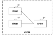
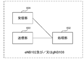
- UE 122 shown in FIG. 5 includes a receiving unit 500 that receives an RRC message or the like from a base station device, a processing unit 502 that performs processing according to parameters included in the received message, and a transmitting unit that transmits the RRC message or the like to the base station device. consists of 504.
- the base station apparatus described above may be eNB 102 or gNB 108 .
- processing unit 502 may include some or all of the functionality of various layers (eg, physical layer, MAC layer, RLC layer, PDCP layer, SDAP layer, RRC layer, and NAS layer). That is, the processing unit 502 includes part or all of the physical layer processing unit, MAC layer processing unit, RLC layer processing unit, PDCP layer processing unit, SDAP processing unit, RRC layer processing unit, and NAS layer processing unit. you can
- FIG. 9 is a diagram showing the procedure flow for setting MBMS reception using SC-PTM.
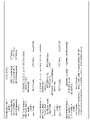
- FIG. 10 is a diagram showing an example of ASN.1 description representing fields and/or information elements included in SIB20 (System Information Block Type 20) in FIG.
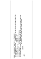
- FIG. 11 is a diagram showing an example of ASN.1 description representing fields and/or information elements included in the SC-PTM configuration message (SCPTMConfiguration) in FIG.
- SC-PTM configuration information includes control information applicable to MBMS reception.
- SC-PTM configuration information is represented by scptm-NeighbourCellList, which is a field represented by sc-mtch-InfoList, which includes the configuration of each SC-MTCH in the cell that transmits the information, and a list of neighboring cells that provide MBMS. field, and/or some or all of the information elements.
- MBS may define one or more delivery modes.
- a delivery mode of MBS with high QoS requirements may be defined.
- a high QoS requirement may include a requirement for high reliability or a requirement for low delay.
- a delivery mode of MBS with low QoS requirements may be defined.
- the delivery mode of MBS with high QoS requirements is called delivery mode 1, but it may be called by another name.
- the distribution mode of MBS with low QoS requirements is called distribution mode 2, but it may be called by other names.
- the reception of MBS sessions delivered in delivery mode 1 may be possible in UE 122 in RRC_CONNECTED state, and may not be possible in UE 122 in RRC_INACTIVE state and/or RRC_IDLE state. Also, reception of an MBS session delivered in delivery mode 1 may be possible in a UE 122 in RRC_CONNECTED state, and a UE 122 that initiated reception of the MBS session described above in RRC_CONNECTED state may enter RRC_INACTIVE state and/or RRC_IDLE state. It may be possible even after the state transition. Reception of MBS sessions delivered in delivery mode 2 may be possible for UEs 122 in RRC_CONNECTED state and/or RRC_INACTIVE state and/or RRC_IDLE state.
- the UE 122 may establish and/or configure an MBS radio bearer for MBS reception.
- an MBS radio bearer can be established and/or configured at the gNB 108 for MBS transmission.
- the name MRB Multicast Radio Bearer
- UE 122 may establish and/or configure MRBs according to parameters included in RRC messages received from gNB 108 .
- UE 122 may also establish and/or configure MRBs according to default information held by UE 122 .
- UE 122 may also establish and/or configure MRBs according to parameters included in RRC messages received from gNB 108 and default information held by UE 122 .
- the MRB has a leg for receiving MBS one-to-many (Point-to-Multipoint) and a leg for receiving MBS one-to-one (Point-to-Point). Legs can be established and/or configured. Also, only legs for receiving MBS one-to-many may be established and/or configured in the MRB. Also, the MRB may only establish and/or configure legs for receiving MBS one-to-one.
- the leg mentioned above may be an RLC bearer. Also, the above-mentioned leg may be a logical channel.
- the term MTCH Multicast Traffic Channel
- UE 122 may establish and/or configure identifiers to identify MBS transmissions using MTCH according to RRC messages received from gNB 108 .
- G-RNTI Group Radio Network Temporary Identifier
- G-RNTI Group Radio Network Temporary Identifier
- G-CS-RNTI Group Configured Scheduling Radio Network Temporary Identifier
- G-RNTI and MBS session may be one-to-one mapping, and information for identifying G-RNTI and MBS session may be one-to-one correspondence. good.
- G-CS-RNTI and MBS session may be one-to-one mapping, and information for identifying G-CS-RNTI and MBS session is one-to-one.
- the above MTCH may be a multicast and/or broadcast traffic channel. Also, the above MTCH may be used by UE 122 only when UE 122 receives MBS. Also, another term such as MBS-MTCH or NR-MTCH may be used for MTCH.
- the above MTCH can be mapped to DL-SCH, which is a downlink transport channel.
- the one-to-one reception of MBS may be reception of MBS transmitted using a dedicated user data logical channel such as a DTCH logical channel. Also, MBS one-to-one reception may be performed by receiving a downlink assignment on the PDCCH for the C-RNTI. Also, MBS one-to-one reception may be performed by receiving in configured downlink scheduling for CS-RNTI (Configured Scheduling Radio Network Temporary Identifier).
- CS-RNTI Configured Scheduling Radio Network Temporary Identifier
- DRB may be used when receiving MBS on a one-to-one basis.
- DRB and MRB may be distinguished by the difference in AS security functions of the PDCP layer.
- a PDCP entity established in an MRB may not be configured with AS security.
- the PDCP entity established in the MRB may be configured with a second AS security different from the first AS security configured for the PDCP entity established in the DRB.
- the PDCP entity established in the MRB has a fourth AS security different from the third AS security set in the PDCP entity established in the DRB associated with the same PDU session as the PDU session associated with the above MRB.
- Security should be set.
- AS security may be ciphering and deciphering and/or integrity protection and verification.
- the term MCCH Multicast Control Channel
- the term MCCH is used for the one-to-many downlink channel (downlink logical channel) for transmitting MBS control information for one or more MTCHs described above.
- MBS-MCCH and NR-MCCH may be used for the MCCH described above.
- the MCCH mentioned above may be a multicast and/or broadcast control channel.
- the above-mentioned MCCH may be mapped to DL-SCH, which is a downlink transport channel.
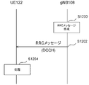
- FIG. 12 is an example of means for establishing and/or setting MBS for delivery mode 1 in an embodiment of the present invention.
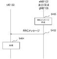
- processing section 602 of gNB 108 creates an RRC message (step S1200).
- the RRC message described above may include parameters necessary for UE 122 to establish and/or configure MRBs for delivery mode 1.
- the information element represented by MRB-Identity in the MRB setting information element is information on the MRB identifier (MRB Identity) of the MRB to be added or changed, and is an identifier that uniquely identifies the MRB in each terminal device. good.
- the information element represented by MRB-Identity in the MRB setting information element can be rephrased as the MRB identifier information element or MRB identifier.
- the MRB identifier may be rephrased as a radio bearer identifier.
- the MRB configuration information element may include some or all parameters of the SDAP configuration information element and PDCP configuration information element described in FIG. Also, as described in FIG. 7, the SDAP configuration information element may contain a PDU session identifier.
- the information element represented by MRB-ToReleaseList may be an information element indicating the list of MRBs to be released.
- the information element indicating the list of MRBs to be released may contain the MRB identifiers of the MRBs to be released.
- the information element denoted MRB-Identity in the RLC bearer setup is the MRB identifier mentioned above and may be the MRB identifier of the MRB with which the RLC bearer established and/or configured by this RLC bearer setup is associated.
- the information element represented by RLC-Config in the RLC bearer setting may be an information element indicating the RLC setting.
- the information element represented by RLC-Config may be rephrased as an RLC configuration information element or RLC configuration.
- the RLC bearer setting includes information indicating that the RLC bearer is for receiving MBS in one-to-many, information indicating whether or not the RLC bearer is for receiving MBS in one-to-many, and MBS in one-to-many.
- Information indicating that the RLC bearer is for one-to-one reception, information indicating whether or not the RLC bearer is for one-to-one reception of MBS, etc. may be included (not shown).
- the RRC message created by the processing unit 602 of the gNB 108 may include information on G-RNTI and/or G-CS-RNTI.
- the G-RNTI and/or G-CS-RNTI information mentioned above may be included in the RLC bearer configuration and may be included in the MRB configuration (not shown).
- the MRB configuration information element may also contain information elements and/or fields indicating MAC logical channels for RLC bearers for one-to-many reception of MBS.
- the MRB configuration information element may also contain information elements and/or fields indicating MAC logical channels for RLC bearers for receiving MBS one-to-one (not shown).
- the receiving unit 500 of the UE 112 may receive the RRC message described above, and the processing unit 502 of the UE 122 may establish and/or set the MRB for delivery mode 1 according to the received RRC message (step S1204).
- the processing unit 502 of the UE 112 determines that the MRB to be established and/or configured is the MRB for distribution mode 1, based on the fact that the received RRC message is the RRC message transmitted from the gNB 108 using the DCCH logical channel. You can judge things.
- the processing unit 502 of the UE 112 may determine that the MRB to be established and/or configured is the delivery mode 1 MRB based on the fact that the received RRC message is the RRC reconfiguration message.
- FIG. 14 is an example of means for establishing and/or setting MBS for delivery mode 2 in an embodiment of the present invention. It is a figure which shows.
- processing section 602 of gNB 108 creates a first SIB (System Information Block), which is one of the RRC messages, in order to broadcast information necessary to acquire control information related to MBS transmission. , may be transmitted from the transmission unit 600 to the UE 122 .
- a receiving unit 500 of UE 122 receives the above-described first SIB.
- the first SIB described above may be transmitted via the BCCH logical channel or via another logical channel.
- the information necessary for obtaining control information regarding MBS transmission described above may be information regarding MCCH.
- the processing unit 602 of the gNB 108 may create an RRC message to be transmitted on the MCCH described above and transmit it from the transmitting unit 600.
- the receiving unit 500 of the UE 122 may receive the RRC message transmitted on the MCCH described above based on the configuration of the first SIB described above.
- a dedicated RNTI Radio Network Temporary Identifier
- the dedicated RNTI value for identifying the MCCH transmission described above may be a specific value, or the value may be set by the first SIB described above.
- the RRC message transmitted on the above-mentioned MCCH is explained using the message name MBS setting information message, but another message name may be used.
- the above MBS setting information message may contain one or more MTCH parameters, which are parameters for MBS reception.
- the MTCH parameter is one or more MTCH parameters, such that the information element indicated by SC-MTCH-InfoList in FIG. 11 contains one or more information elements indicated by SC-MTCH-Info in the form of a list.
- the parameters can be included in the MBS Configuration Information message mentioned above in the form of a list.
- An MTCH parameter may also exist for each MBS session. For example, there may be a first MTCH parameter for the first MBS session and a second MTCH parameter for the second MBS session.
- the parameters for MBS reception described above are described using the name of MTCH parameters, but other names may be used.
- the MTCH parameters include parameters related to MBS session information, parameters indicating RNTI identifying multicast and/or broadcast groups (MTCHs addressed to specific groups), parameters indicating logical channel identifiers, parameters relating to DRX information for MTCH, and the same It may include some or all of the parameters that indicate the list of neighbor cells that offer the MBS.
- the parameter indicating the RNTI identifying the multicast and/or broadcast group (MTCH destined for a specific group) mentioned above may be G-RNTI.
- the parameters related to the MBS session information described above include, for example, a parameter indicating the TMGI (Temporary Mobile Group Identity) that is the identifier that identifies the MBS, a parameter that indicates the Session ID that is the MBS session identifier, and a PDU session to which the MBS session belongs. It may include some or all of the parameters, such as parameters indicating the QoS flow used for the MBS session.
- TMGI Temporal Mobile Group Identity
- the parameter indicating the list of neighboring cells providing the same MBS described above may include a parameter indicating the list of neighboring cells providing the same MBS via MTCH and/or MRB, A parameter may be included that indicates a list of neighboring cells that provide the same MBS via unicast and/or DTCH and/or DRB.
- the RLC bearer setting information element described above may be included in an information element different from the MRB setting, and may be linked to the parameters related to the MRB setting by the identifier for identifying the MRB described above.
- the MRB configuration described above may also include parameters that identify the RLC bearers that receive the MBS one-to-many.
- the MRB configuration described above may also include a parameter that identifies the RLC bearer that receives the MBS on a one-to-one basis.
- the parameter identifying the RLC bearer that receives the MBS one-to-many and/or the RLC bearer that receives the MBS one-to-one may be logical channel identifiers. Note that the MRB for delivery mode 2 does not have to have an RLC bearer that receives MBS on a one-to-one basis. In other words, the MRB for distribution mode 2 may have a function of receiving MBS only one-to-many.
- the processing unit 502 of the UE 122 may determine that the MRB that has been established and/or configured is a delivery mode 2 MRB based on the fact that this MRB is not associated with a PDU session. Note that from step S1400 to step S1404, the UE 122 may be in any of RRC_CONNECTED state, RRC_INACTIVE state, and RRC_IDLE state.
- UE 122 when UE 122 establishes and/or configures an MRB, only default information held by UE 122 may be used. Also, when UE 122 establishes and/or configures an MRB, default information held by UE 122 may be used in addition to the information required for MRB establishment and/or configuration contained in the RRC message received from gNB 108 . Also, when UE 122 establishes and / or sets the MRB for delivery mode 1, in addition to the information necessary for MRB establishment and / or setting included in the RRC message received from gNB 108 via DCCH, the following (A) and (B) may be used. (A) Default information held by UE 122 (B) Information required for MRB establishment and/or configuration included in the RRC message received from gNB 108 via MCCH
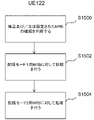
- FIG. 15 is a diagram showing a first example of processing in UE 122 according to the embodiment of the present invention.
- the processing unit 502 of the UE 122 may determine whether the established and/or configured MRB is an MRB for delivery mode 1 or an MRB for delivery mode 2 (step S1500).
- Processing unit 502 of UE 112 may determine this MRB as a delivery mode 1 MRB based on the fact that the MRB was established and/or configured according to the RRC message sent from gNB 108 using the DCCH logical channel.
- the processing unit 502 of the UE 112 may determine that the MRB is a delivery mode 1 MRB based on the fact that the MRB was established and/or configured according to the RRC reconfiguration message sent from the gNB 108 .
- the above-mentioned RRC re-establishment procedure normal completion may mean that UE 122 receives an RRC re-establishment message, which is a response message from gNB 108 in response to the RRC re-establishment request message sent from UE 122 to gNB 108 .
- the above-mentioned RRC re-establishment procedure normal completion means that UE 122 receives an RRC re-establishment message that is a response message from gNB 108 in response to the RRC re-establishment request message transmitted from UE 122 to gNB 108, UE 122 to gNB 108, It may be to send an RRC re-establishment complete message.
- the processing unit 502 of the UE 122 may perform the dedicated wireless setting release process set in the UE 122.
- the G-RNTI and/or G-CS-RNTI release process may be excluded.
- the G-CS-RNTI release process may be excluded.
- the G-RNTI and/or G-CS-RNTI described above may be parameters included in an RRC message transmitted from the base station apparatus using the DCCH logical channel.
- the RRC message transmitted using the DCCH logical channel described above may be an RRC reconfiguration message or another RRC message.
- FIG. 19 is a diagram showing a fifth example of processing in UE 122 according to the embodiment of the present invention.
- the receiving unit 500 of the UE 122 receives an RRC message instructing handover from NR to the second RAT from the gNB 108 (step S1900).
- the above RRC message instructing handover from NR to the second RAT may be an RRC message named MobilityFromNRCommand.
- the first RRC message described in (1) to (4) is an RRC message transmitted from the base station apparatus to the terminal apparatus using a DCCH logical channel.
- the first type MRB described in (1) to (4) is associated with a PDU session.
- a program that runs on a device is a program that controls a Central Processing Unit (CPU) or the like to function a computer so as to realize the functions of the above-described embodiments according to one aspect of the present invention. It can be.
- the program or information handled by the program is temporarily read into volatile memory such as Random Access Memory (RAM) during processing, or stored in non-volatile memory such as flash memory or Hard Disk Drive (HDD), and
- RAM Random Access Memory
- HDD Hard Disk Drive
- each functional block or feature of the apparatus used in the embodiments described above may be implemented or performed in an electrical circuit, typically an integrated circuit or multiple integrated circuits.
- Electrical circuits designed to perform the functions described herein may be general purpose processors, digital signal processors (DSPs), application specific integrated circuits (ASICs), field programmable gate arrays (FPGAs), or other programmable logic devices, discrete gate or transistor logic, discrete hardware components, or combinations thereof.
- a general purpose processor may be a microprocessor, in the alternative, the processor may be any conventional processor, controller, microcontroller, or state machine.
- the general-purpose processor or each circuit described above may be composed of digital circuits or may be composed of analog circuits.
- an integrated circuit technology that replaces current integrated circuits emerges due to advances in semiconductor technology, it is also possible to use integrated circuits based on this technology.
- One aspect of the present invention is, for example, a communication system, a communication device (e.g., a mobile phone device, a base station device, a wireless LAN device, or a sensor device), an integrated circuit (e.g., a communication chip), or a program, etc. be able to.
- a communication device e.g., a mobile phone device, a base station device, a wireless LAN device, or a sensor device
- an integrated circuit e.g., a communication chip
- a program etc. be able to.
Landscapes
- Engineering & Computer Science (AREA)
- Computer Networks & Wireless Communication (AREA)
- Signal Processing (AREA)
- Multimedia (AREA)
- Mobile Radio Communication Systems (AREA)
Abstract
Description
本願は、2021年6月2日に日本に出願された特願2021-92654号について優先権を主張し、その内容をここに援用する。
PDCCH(物理下りリンク制御チャネル:Physical Downlink Control CHannel)
PDSCH(物理下りリンク共用チャネル:Physical Downlink Shared CHannel)
PUCCH(物理上りリンク制御チャネル:Physical Uplink Control CHannel)
PUSCH(物理上りリンク共用チャネル:Physical Uplink Shared CHannel)
PRACH(物理ランダムアクセスチャネル:Physical Random Access CHannel)
(A) AM RLCエンティティの送信側で使われる応答ステート変数。次にポジティブ応答を受信する事になるRLC SDUのシーケンス番号の値を示す。TX_Next_Ackという名称のステート変数であって良い。
(B) AM RLCエンティティの送信側で使われる送信ステート変数。次に新しく作られるAMD PDUにアサインされるシーケンス番号の値を示す。TX_Nextという名称のステート変数であって良い。
(C) AM RLCエンティティの送信側で使われるポールステート変数。本ステート変数がセットされる際に下位レイヤに提出されるAMD PDUのうちで最も大きなシーケンス番号の値を示す。POLL_SNという名称のステート変数であって良い。
(D) AM RLCエンティティの受信側で使われる受信ステート変数。順序通りでの受信が成功したRLC SDUの最後のシーケンス番号に続く値を示す。RX_Nextという名称のステート変数であって良い。
(E) AM RLCエンティティの受信側で使われるリアセンブリタイマーステート変数。リアセンブリタイマーを起動させたAMD PDUのシーケンス番号の次のシーケンス番号の値を示す。RX_Next_Status_Triggerという名称のステート変数であって良い。
(F) AM RLCエンティティの受信側で使われる最大STATUS送信ステート変数。ステータスPDUを作成する必要がある際に、受信成功したAMD PDUとして報告するAMD PDUのシーケンス番号の値を示す。RX_Highest_Statusという名称のステート変数であって良い。
(G) AM RLCエンティティの受信側で使われる最高受信ステート変数。受信したAMD PDUの中での最も高いシーケンス番号の値の次のシーケンス番号の値を示す。RX_Next_Highestという名称のステート変数であって良い。
(H) UM RLCエンティティの送信側で使われる送信ステート変数。次に新しく作られるUMD PDUがセグメントされる場合にアサインされるシーケンス番号の値を示す。TX_Nextという名称のステート変数であって良い。
(I) UM RLCエンティティの受信側で使われるUM受信ステート変数。リアセンブリが考えられるUMD PDUのシーケンス番号うちの最小値を示す。RX_Next_Reassemblyという名称のステート変数であって良い。
(J) UM RLCエンティティの受信側で使われるUMリアセンブリタイマーステート変数。リアセンブリタイマーを起動させたUMD PDUのシーケンス番号の次のシーケンス番号の値を示す。RX_Timer_Triggerという名称のステート変数であって良い。
(K) UM RLCエンティティの受信側で使われるUM受信ステート変数。受信したUMD PDUの中での最も高いシーケンス番号の値の次のシーケンス番号の値を示す。RX_Next_Highestという名称のステート変数であって良い。
(A) 最後のポールビット送信以降に送られたAMD PDUの数をカウントするカウンター。PDU_WITHOUT_POLLという名称のカウンターであって良い。
(B) 最後のポールビット送信以降に送られたデータのバイト数をカウントするカウンター。BYTE_WITHOUT_POLLという名称のカウンターであって良い。
(C) RLC SDU又はRLC SDUセグメントが再送された回数をカウントするカウンター。RETX_COUNTという名称のカウンターであって良い。
(A) AM RLCエンティティの送信側で使われる、ポールを再送するためのタイマー。t-PollRetransmitという名称のタイマーであって良い。
(B) AM RLCエンティティの受信側及び受信UM RLCエンティティで使われる、RLC PDUのロス(loss)を検出するためのタイマー。t-Reassemblyという名称のタイマーであって良い。
(C) AM RLCエンティティの受信側で使われる、ステータスPDUの送信を禁止するためのタイマー。t-StatusProhibitという名称のタイマーであって良い。
(A)次に送信されるPDCP SDUのCOUNT値を示すステート変数。TX_NEXTという名称のステート変数であって良い。
(B)本PDCPエンティティにおいて、次に送信されるPDCP SDUのシーケンス番号を示すステート変数。Next_PDCP_TX_SNという名称のステート変数であって良い。
(C)本PDCPエンティティにおいて、PDCP PDUのCOUNT値を生成するために使われるHFN値を表すステート変数。TX_HFNという名称のステート変数であって良い。
(D)受信PDCPエンティティにおいて、次に受信する事が期待(expect)されるPDCP SDUのCOUNT値を示すステート変数。RX_NEXTという名称のステート変数であって良い。
(E)受信PDCPエンティティにおいて、次に受信する事が期待(expect)されるPDCP SDUのシーケンス番号を示すステート変数。Next_PDCP_RX_SNという名称のステート変数であって良い。
(F)本PDCPエンティティにおいて、受信したPDCP PDUに対するCOUNT値を生成するために使われるHFN値を表すステート変数。RX_HFNという名称のステート変数であって良い。
(A)受信PDCPエンティティにおいて、次に受信する事が期待(expect)されるPDCP SDUのCOUNT値を示すステート変数。RX_NEXTという名称のステート変数であって良い。
(B)受信PDCPエンティティにおいて、次に受信する事が期待(expect)されるPDCP SDUのシーケンス番号を示すステート変数。Next_PDCP_RX_SNという名称のステート変数であって良い。
(C)本PDCPエンティティにおいて、受信したPDCP PDUに対するCOUNT値を生成するために使われるHFN値を表すステート変数。RX_HFNという名称のステート変数であって良い。
(D)受信PDCPエンティティにおいて、上位層に配信していない受信待ちのPDCP SDUのうち最初のPDCP PDUのCOUNT値を示すステート変数。RX_DELIVという名称のステート変数であって良い。
(E)受信PDCPエンティティにおいて、最後に上位層に配信したPDCP SDUのPDCP PDUのシーケンス番号を示すステート変数。Last_Submitted_PDCP_RX_SNという名称のステート変数であって良い。
(F)受信PDCPエンティティにおいて、リオーダリングタイマーを開始させたPDCP PDUのCOUNT値の次のCOUNT値を示すステート変数。RX_REORDという名称のステート変数、又はReordering_PDCP_RX_COUNTという名称のステート変数であって良い。
(A)上位レイヤがPDCPエンティティの再確立(re-establishment)を要求する。
(B)上位レイヤがPDCPデータリカバリを要求する。
(C)上位レイヤがアップリンクデータスイッチを要求する。
(D)上位レイヤがDAPS(Dual Active Protocol Stack)を解放するためにこのPDCPエンティティを再設定し、かつdaps source releaseという名称のパラメータが設定されている。
(A)SC-MCCH及びSC-MTCHのデフォルト設定に従って、RLCエンティティを確立する。
(B)確立するSC-MRBに適用するSC-MTCH論理チャネルを設定し、MACエンティティを、上述のSC-PTM設定メッセージを受信したセルに対し、上述のSC-PTM設定メッセージに従って、当該MBMSセッションを受信できるようインストラクト(instruct)する。
(C)確立するSC-MRBに対し、物理レイヤを上述のsc-mtch-InfoListに基づいて設定する。
(D)上位レイヤに対し、確立したSC-MRBに対応するtmgiとsessionIdを通知(indicate)する事により、SC-MRBの確立を知らせる。
(A)解放するSC-MRBのRLCエンティティ、及び関連するMACと物理レイヤ設定を解放する。
(B)上位レイヤに対し、解放したSC-MRBに対応するtmgiとsessionIdを通知する事により、SC-MRBの解放を知らせる。
(A) UE122が保有するデフォルト情報
(B) gNB108からMCCHを介して受信したRRCメッセージに含まれる、MRB確立及び/又は設定に必要な情報
(A) 上述の追加されない各PDUセッションに対するユーザプレーンリソースが解放された事を、上位レイヤに通知する。
102 eNB
104 EPC
106 NR
108 gNB
110 5GC
112、114、116、118、120、124 インタフェース
122 UE
200、300 PHY
202、302 MAC
204、304 RLC
206、306 PDCP
208、308 RRC
310 SDAP
210、312 NAS
500、604 受信部
502、602 処理部
504、600 送信部
Claims (7)
- 基地局装置と通信する端末装置であって、
前記基地局装置から、第1のRRCメッセージ及び/又は第2のRRCメッセージを受信する受信部と、処理部とを備え、
前記処理部は、前記第1のRRCメッセージによって第1のタイプのMRBが確立された場合には、全ての無線ベアラを解放する場合、前記第1のタイプのMRBを解放し、
前記第2のRRCメッセージによって第2のタイプのMRBが確立された場合には、前記全ての無線ベアラを解放する場合、前記第2のタイプのMRBを解放しない、
端末装置。 - 前記第1のRRCメッセージは、前記基地局装置からDCCHロジカルチャネルを用いて送信されるRRCメッセージである、
請求項1に記載の端末装置。 - 前記第2のRRCメッセージは、前記基地局装置からMCCHロジカルチャネルを用いて送信されるRRCメッセージである、
請求項1に記載の端末装置。 - 端末装置と通信する基地局装置であって、
前記端末装置に、第1のRRCメッセージ及び/又は第2のRRCメッセージを送信する送信部と、処理部とを備え、
前記処理部は、前記端末装置に対し、前記第1のRRCメッセージによって第1のタイプのMRBが確立された場合には、全ての無線ベアラを解放する場合、前記第1のタイプのMRBを解放させ、
前記第2のRRCメッセージによって第2のタイプのMRBが確立された場合には、前記全ての無線ベアラを解放する場合、前記第2のタイプのMRBを解放させない、
基地局装置。 - 前記第1のRRCメッセージは、前記端末装置にDCCHロジカルチャネルを用いて送信するRRCメッセージである、
請求項4に記載の基地局装置。 - 前記第2のRRCメッセージは、前記端末装置にMCCHロジカルチャネルを用いて送信するRRCメッセージである、
請求項4に記載の基地局装置。 - 基地局装置と通信する端末装置の方法であって、
前記基地局装置から、第1のRRCメッセージ及び/又は第2のRRCメッセージを受信し、
前記第1のRRCメッセージによって第1のタイプのMRBが確立された場合には、全ての無線ベアラを解放する場合、前記第1のタイプのMRBを解放し、
前記第2のRRCメッセージによって第2のタイプのMRBが確立された場合には、前記全ての無線ベアラを解放する場合、前記第2のタイプのMRBを解放しない、
方法。
Priority Applications (3)
| Application Number | Priority Date | Filing Date | Title |
|---|---|---|---|
| US18/565,780 US20240260118A1 (en) | 2021-06-02 | 2022-05-30 | Terminal apparatus, base station apparatus, and method |
| CN202280039278.2A CN117413541A (zh) | 2021-06-02 | 2022-05-30 | 终端装置、基站装置以及方法 |
| EP22816041.2A EP4351176A4 (en) | 2021-06-02 | 2022-05-30 | Terminal device, base station device and method |
Applications Claiming Priority (2)
| Application Number | Priority Date | Filing Date | Title |
|---|---|---|---|
| JP2021092654A JP2024102386A (ja) | 2021-06-02 | 2021-06-02 | 端末装置、基地局装置、および方法 |
| JP2021-092654 | 2021-06-02 |
Publications (1)
| Publication Number | Publication Date |
|---|---|
| WO2022255293A1 true WO2022255293A1 (ja) | 2022-12-08 |
Family
ID=84323258
Family Applications (1)
| Application Number | Title | Priority Date | Filing Date |
|---|---|---|---|
| PCT/JP2022/021915 Ceased WO2022255293A1 (ja) | 2021-06-02 | 2022-05-30 | 端末装置、基地局装置、および方法 |
Country Status (5)
| Country | Link |
|---|---|
| US (1) | US20240260118A1 (ja) |
| EP (1) | EP4351176A4 (ja) |
| JP (1) | JP2024102386A (ja) |
| CN (1) | CN117413541A (ja) |
| WO (1) | WO2022255293A1 (ja) |
Families Citing this family (1)
| Publication number | Priority date | Publication date | Assignee | Title |
|---|---|---|---|---|
| US20240284556A1 (en) * | 2023-02-16 | 2024-08-22 | Samsung Electronics Co., Ltd. | Configuring user equipment for multicast reception in telecommunication network |
Citations (2)
| Publication number | Priority date | Publication date | Assignee | Title |
|---|---|---|---|---|
| EP2367395A1 (en) * | 2010-03-17 | 2011-09-21 | HTC Corporation | Apparatus and methods for handling network initiated connection release procedures |
| JP2021092654A (ja) | 2019-12-10 | 2021-06-17 | 日本電産サンキョー株式会社 | 振れ補正機能付き光学ユニット |
Family Cites Families (4)
| Publication number | Priority date | Publication date | Assignee | Title |
|---|---|---|---|---|
| KR20060041673A (ko) * | 2004-08-16 | 2006-05-12 | 엘지전자 주식회사 | 방송 및 멀티캐스트(mbms) 서비스를 위한 무선 통신시스템 및 방법 |
| CN100571453C (zh) * | 2005-08-23 | 2009-12-16 | 华为技术有限公司 | 响应mbms修正业务消息的方法 |
| CN116114272A (zh) * | 2020-08-05 | 2023-05-12 | 交互数字专利控股公司 | 5g多播广播服务(mbs)无线电接入网络架构和操作 |
| US12439475B2 (en) * | 2021-03-30 | 2025-10-07 | Samsung Electronics Co., Ltd. | Methods and user equipment (UE) for handling MBS service in wireless network |
-
2021
- 2021-06-02 JP JP2021092654A patent/JP2024102386A/ja active Pending
-
2022
- 2022-05-30 CN CN202280039278.2A patent/CN117413541A/zh active Pending
- 2022-05-30 WO PCT/JP2022/021915 patent/WO2022255293A1/ja not_active Ceased
- 2022-05-30 US US18/565,780 patent/US20240260118A1/en active Pending
- 2022-05-30 EP EP22816041.2A patent/EP4351176A4/en active Pending
Patent Citations (2)
| Publication number | Priority date | Publication date | Assignee | Title |
|---|---|---|---|---|
| EP2367395A1 (en) * | 2010-03-17 | 2011-09-21 | HTC Corporation | Apparatus and methods for handling network initiated connection release procedures |
| JP2021092654A (ja) | 2019-12-10 | 2021-06-17 | 日本電産サンキョー株式会社 | 振れ補正機能付き光学ユニット |
Non-Patent Citations (5)
| Title |
|---|
| "Evolved Universal Terrestrial Radio Access (E-UTRA) and Evolved Universal Terrestrial Radio Access Network (E-UTRAN); Overall description; Stage 2", 3GPP TS 36.300, pages 19 - 361 |
| "NR; NR and NG-RAN Overall description; Stage 2", 3GPP TS 38.300V, pages 10 - 134 |
| HUAWEI, HISILICON: "On the general aspects for delivery mode 1 and 2", 3GPP DRAFT; R2-2101186, 3RD GENERATION PARTNERSHIP PROJECT (3GPP), MOBILE COMPETENCE CENTRE ; 650, ROUTE DES LUCIOLES ; F-06921 SOPHIA-ANTIPOLIS CEDEX ; FRANCE, vol. RAN WG2, no. E-meeting; 20210125 - 20210205, 15 January 2021 (2021-01-15), Mobile Competence Centre ; 650, route des Lucioles ; F-06921 Sophia-Antipolis Cedex ; France , XP051974165 * |
| OPPO: "RRC state control for MBS reception", 3GPP DRAFT; R2-2102896, 3RD GENERATION PARTNERSHIP PROJECT (3GPP), MOBILE COMPETENCE CENTRE ; 650, ROUTE DES LUCIOLES ; F-06921 SOPHIA-ANTIPOLIS CEDEX ; FRANCE, vol. RAN WG2, no. electronic; 20210412 - 20210420, 2 April 2021 (2021-04-02), Mobile Competence Centre ; 650, route des Lucioles ; F-06921 Sophia-Antipolis Cedex ; France, XP052174468 * |
| See also references of EP4351176A4 |
Also Published As
| Publication number | Publication date |
|---|---|
| CN117413541A (zh) | 2024-01-16 |
| EP4351176A4 (en) | 2025-05-28 |
| EP4351176A1 (en) | 2024-04-10 |
| JP2024102386A (ja) | 2024-07-31 |
| US20240260118A1 (en) | 2024-08-01 |
Similar Documents
| Publication | Publication Date | Title |
|---|---|---|
| US20230396367A1 (en) | Terminal apparatus, base station apparatus, and method | |
| US20230309185A1 (en) | Terminal apparatus, base station apparatus, and method | |
| JP7741088B2 (ja) | 端末装置、基地局装置、および方法 | |
| US12526606B2 (en) | Terminal apparatus, method, and integrated circuit | |
| EP4145937B1 (en) | Terminal device, method, and integrated circuit | |
| WO2022255288A1 (ja) | 端末装置、基地局装置、および方法 | |
| EP4351176A1 (en) | Terminal device, base station device, and method | |
| EP4195714B1 (en) | Terminal device, base station device, and method | |
| WO2022138567A1 (ja) | 端末装置、基地局装置、および方法 | |
| WO2022080300A1 (ja) | 端末装置および方法 | |
| WO2022131342A1 (ja) | 端末装置、基地局装置、および、方法 | |
| JP7772709B2 (ja) | 端末装置および方法 | |
| JP7850671B2 (ja) | 端末装置、基地局装置、および方法 | |
| JP7839098B2 (ja) | 端末装置および方法 | |
| EP4351175A1 (en) | Terminal device, base station device, and method | |
| WO2022255303A1 (ja) | 端末装置、基地局装置、および方法 | |
| US20240260119A1 (en) | Terminal apparatus, base station apparatus, and method | |
| WO2023276947A1 (ja) | 端末装置、基地局装置、および方法 |
Legal Events
| Date | Code | Title | Description |
|---|---|---|---|
| 121 | Ep: the epo has been informed by wipo that ep was designated in this application |
Ref document number: 22816041 Country of ref document: EP Kind code of ref document: A1 |
|
| WWE | Wipo information: entry into national phase |
Ref document number: 202280039278.2 Country of ref document: CN Ref document number: 18565780 Country of ref document: US |
|
| WWE | Wipo information: entry into national phase |
Ref document number: 2022816041 Country of ref document: EP |
|
| NENP | Non-entry into the national phase |
Ref country code: DE |
|
| ENP | Entry into the national phase |
Ref document number: 2022816041 Country of ref document: EP Effective date: 20240102 |
|
| NENP | Non-entry into the national phase |
Ref country code: JP |