WO2022255488A1 - 圧縮機 - Google Patents
圧縮機 Download PDFInfo
- Publication number
- WO2022255488A1 WO2022255488A1 PCT/JP2022/022656 JP2022022656W WO2022255488A1 WO 2022255488 A1 WO2022255488 A1 WO 2022255488A1 JP 2022022656 W JP2022022656 W JP 2022022656W WO 2022255488 A1 WO2022255488 A1 WO 2022255488A1
- Authority
- WO
- WIPO (PCT)
- Prior art keywords
- contact surface
- front head
- compressor
- muffler
- boss portion
- Prior art date
- Legal status (The legal status is an assumption and is not a legal conclusion. Google has not performed a legal analysis and makes no representation as to the accuracy of the status listed.)
- Ceased
Links
Images

Classifications
-
- F—MECHANICAL ENGINEERING; LIGHTING; HEATING; WEAPONS; BLASTING
- F04—POSITIVE - DISPLACEMENT MACHINES FOR LIQUIDS; PUMPS FOR LIQUIDS OR ELASTIC FLUIDS
- F04B—POSITIVE-DISPLACEMENT MACHINES FOR LIQUIDS; PUMPS
- F04B39/00—Component parts, details, or accessories, of pumps or pumping systems specially adapted for elastic fluids, not otherwise provided for in, or of interest apart from, groups F04B25/00 - F04B37/00
- F04B39/0027—Pulsation and noise damping means
-
- F—MECHANICAL ENGINEERING; LIGHTING; HEATING; WEAPONS; BLASTING
- F04—POSITIVE - DISPLACEMENT MACHINES FOR LIQUIDS; PUMPS FOR LIQUIDS OR ELASTIC FLUIDS
- F04B—POSITIVE-DISPLACEMENT MACHINES FOR LIQUIDS; PUMPS
- F04B39/00—Component parts, details, or accessories, of pumps or pumping systems specially adapted for elastic fluids, not otherwise provided for in, or of interest apart from, groups F04B25/00 - F04B37/00
- F04B39/12—Casings; Cylinders; Cylinder heads; Fluid connections
- F04B39/125—Cylinder heads
-
- F—MECHANICAL ENGINEERING; LIGHTING; HEATING; WEAPONS; BLASTING
- F04—POSITIVE - DISPLACEMENT MACHINES FOR LIQUIDS; PUMPS FOR LIQUIDS OR ELASTIC FLUIDS
- F04C—ROTARY-PISTON, OR OSCILLATING-PISTON, POSITIVE-DISPLACEMENT MACHINES FOR LIQUIDS; ROTARY-PISTON, OR OSCILLATING-PISTON, POSITIVE-DISPLACEMENT PUMPS
- F04C18/00—Rotary-piston pumps specially adapted for elastic fluids
- F04C18/30—Rotary-piston pumps specially adapted for elastic fluids having the characteristics covered by two or more of groups F04C18/02, F04C18/08, F04C18/22, F04C18/24, F04C18/48, or having the characteristics covered by one of these groups together with some other type of movement between co-operating members
- F04C18/34—Rotary-piston pumps specially adapted for elastic fluids having the characteristics covered by two or more of groups F04C18/02, F04C18/08, F04C18/22, F04C18/24, F04C18/48, or having the characteristics covered by one of these groups together with some other type of movement between co-operating members having the movement defined in group F04C18/08 or F04C18/22 and relative reciprocation between the co-operating members
-
- F—MECHANICAL ENGINEERING; LIGHTING; HEATING; WEAPONS; BLASTING
- F04—POSITIVE - DISPLACEMENT MACHINES FOR LIQUIDS; PUMPS FOR LIQUIDS OR ELASTIC FLUIDS
- F04C—ROTARY-PISTON, OR OSCILLATING-PISTON, POSITIVE-DISPLACEMENT MACHINES FOR LIQUIDS; ROTARY-PISTON, OR OSCILLATING-PISTON, POSITIVE-DISPLACEMENT PUMPS
- F04C18/00—Rotary-piston pumps specially adapted for elastic fluids
- F04C18/30—Rotary-piston pumps specially adapted for elastic fluids having the characteristics covered by two or more of groups F04C18/02, F04C18/08, F04C18/22, F04C18/24, F04C18/48, or having the characteristics covered by one of these groups together with some other type of movement between co-operating members
- F04C18/34—Rotary-piston pumps specially adapted for elastic fluids having the characteristics covered by two or more of groups F04C18/02, F04C18/08, F04C18/22, F04C18/24, F04C18/48, or having the characteristics covered by one of these groups together with some other type of movement between co-operating members having the movement defined in group F04C18/08 or F04C18/22 and relative reciprocation between the co-operating members
- F04C18/356—Rotary-piston pumps specially adapted for elastic fluids having the characteristics covered by two or more of groups F04C18/02, F04C18/08, F04C18/22, F04C18/24, F04C18/48, or having the characteristics covered by one of these groups together with some other type of movement between co-operating members having the movement defined in group F04C18/08 or F04C18/22 and relative reciprocation between the co-operating members with vanes reciprocating with respect to the outer member
-
- F—MECHANICAL ENGINEERING; LIGHTING; HEATING; WEAPONS; BLASTING
- F04—POSITIVE - DISPLACEMENT MACHINES FOR LIQUIDS; PUMPS FOR LIQUIDS OR ELASTIC FLUIDS
- F04C—ROTARY-PISTON, OR OSCILLATING-PISTON, POSITIVE-DISPLACEMENT MACHINES FOR LIQUIDS; ROTARY-PISTON, OR OSCILLATING-PISTON, POSITIVE-DISPLACEMENT PUMPS
- F04C29/00—Component parts, details or accessories of pumps or pumping installations, not provided for in groups F04C18/00 - F04C28/00
- F04C29/06—Silencing
- F04C29/065—Noise dampening volumes, e.g. muffler chambers
-
- F—MECHANICAL ENGINEERING; LIGHTING; HEATING; WEAPONS; BLASTING
- F04—POSITIVE - DISPLACEMENT MACHINES FOR LIQUIDS; PUMPS FOR LIQUIDS OR ELASTIC FLUIDS
- F04C—ROTARY-PISTON, OR OSCILLATING-PISTON, POSITIVE-DISPLACEMENT MACHINES FOR LIQUIDS; ROTARY-PISTON, OR OSCILLATING-PISTON, POSITIVE-DISPLACEMENT PUMPS
- F04C29/00—Component parts, details or accessories of pumps or pumping installations, not provided for in groups F04C18/00 - F04C28/00
- F04C29/06—Silencing
- F04C29/068—Silencing the silencing means being arranged inside the pump housing
-
- F—MECHANICAL ENGINEERING; LIGHTING; HEATING; WEAPONS; BLASTING
- F04—POSITIVE - DISPLACEMENT MACHINES FOR LIQUIDS; PUMPS FOR LIQUIDS OR ELASTIC FLUIDS
- F04C—ROTARY-PISTON, OR OSCILLATING-PISTON, POSITIVE-DISPLACEMENT MACHINES FOR LIQUIDS; ROTARY-PISTON, OR OSCILLATING-PISTON, POSITIVE-DISPLACEMENT PUMPS
- F04C23/00—Combinations of two or more pumps, each being of rotary-piston or oscillating-piston type, specially adapted for elastic fluids; Pumping installations specially adapted for elastic fluids; Multi-stage pumps specially adapted for elastic fluids
- F04C23/008—Hermetic pumps
Definitions
- Patent Document 1 Japanese Unexamined Patent Application Publication No. 05-133377
- a space (shell space) into which fluid compressed in a compression element is discharged is formed by a front head (upper frame) and a muffler cover (muffler).
- a compressor is disclosed.
- the position of the fluid discharge port formed in the muffler cover is adjusted to offset the pressure pulsation of the fluid discharged from the compression element. is reduced.
- the muffler cover of the compressor of Patent Document 1 has an opening for inserting the boss of the front head.
- the muffler cover is attached to the front head, there is a small gap between the opening and the boss, and the fluid compressed by the cylinder flows out from the gap, resulting in sufficient vibration and noise. There is a problem that the effect of reducing the is not obtained.
- the present disclosure proposes a compressor that suppresses vibration and noise caused by pressure pulsation of compressed refrigerant flowing out of the compression mechanism.
- the compressor of the first aspect has a compression mechanism.
- the compression mechanism has a front head with a boss and a muffler cover attached to the front head.
- the front head has a first contact surface that is part of the conical side surface on the outer peripheral surface of the boss.
- the muffler cover has a first surface with a circular first opening into which the boss portion is inserted. A first end of the first surface forming the first opening contacts the first contact surface when the muffler cover is attached to the front head.
- the space between the boss portion and the first opening is sealed by the contact between the first contact surface and the first end of the first surface, and the refrigerant flows from between the boss portion and the first opening. Outflow is suppressed.
- this compressor the generation of vibration and noise due to pressure pulsation of the compressed refrigerant flowing out of the compression mechanism is suppressed.
- the compressor of the second aspect is the compressor of the first aspect, wherein the first surface has a second contact surface that is part of a conical side surface formed around the first opening. The second contact surface contacts the first contact surface when the muffler cover is attached to the front head.
- the space between the boss portion and the first opening is sealed by the contact between the first contact surface and the second contact surface, and the refrigerant can flow out from between the boss portion and the first opening. Suppressed.
- this compressor the generation of vibration and noise due to pressure pulsation of the compressed refrigerant flowing out of the compression mechanism is suppressed.
- the compressor of the third aspect is the compressor of the first aspect or the second aspect, and the muffler cover is formed with two second openings through which the fluid compressed by the compression mechanism passes.
- the two second openings are formed at positions spaced apart by 180° around the axis of the boss on a circle with a predetermined radius centered on the axis of the boss when viewed from the extending direction of the boss. .
- the refrigerant discharged from the second opening becomes a symmetrical sound source, and the generation of vibration and noise caused by pressure pulsation of the compressed refrigerant is effectively suppressed.
- a compressor according to a fourth aspect is the compressor according to the second aspect or the third aspect, wherein the angle formed between the axis of the boss and the first contact surface on a plane including the axis of the boss is is smaller than the angle formed by the axis of and the second contact surface.
- the second contact surface is elastically deformed to come into surface contact with the first contact surface, resulting in pressure pulsation of the compressed refrigerant.
- the generation of vibrations and noise caused by this is effectively suppressed.
- the compressor of the fifth aspect is any one of the compressors of the second to fourth aspects, and the width of the second contact surface is greater than the plate thickness of the muffler cover.
- the elastic deformation of the second contact surface can ensure the sealing performance, and the pressure of the compressed refrigerant can be reduced. Generation of vibration and noise caused by pulsation is effectively suppressed.
- a compressor according to a sixth aspect is the compressor according to any one of the first aspect to the fifth aspect, wherein the angle formed between the axis of the boss and the first contact surface on a plane including the axis of the boss is , greater than 0° and less than 45°.
- the volume of the space formed by the muffler cover and the front head due to an excessive increase in the outer diameter of the boss portion below the first contact surface is suppressed. Vibration and noise caused by pressure pulsation of the refrigerant are effectively suppressed.
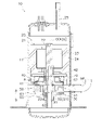
- FIG. 1 is a schematic longitudinal sectional view of a compressor 10 according to a first embodiment
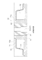
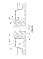
- FIG. FIG. 2 is an enlarged view of a portion A surrounded by a dotted line in FIG. 1
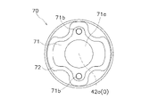
- 4 is a plan view of the muffler cover 70 as viewed from above
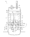
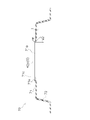
- FIG. It is a schematic longitudinal cross-sectional view of the compressor 10 which concerns on 2nd Embodiment.
- 5 is an enlarged view of a portion B surrounded by a dotted line in FIG. 4
- FIG. FIG. 5 is a cross-sectional view of a muffler cover 70 included in a compressor 10 according to a second embodiment
- 5 is a graph showing analysis results using models according to Examples and Comparative Examples.
- FIG. 1 is a schematic longitudinal sectional view of a compressor 10 according to the first embodiment.
- FIG. 2 is an enlarged view of part A surrounded by a dotted line in FIG.
- the compressor 10 is a rotary compressor that compresses fluid to a predetermined pressure by eccentrically rotating a piston inside a cylinder to change the volume of the space inside the cylinder.
- the compressor 10 is used for compressing refrigerant in a refrigeration cycle apparatus such as an air conditioner or a heat pump water heater.
- the compressor 10 includes a substantially cylindrical casing 11 that is a closed container, a drive mechanism 20 housed in the casing 11, and a compression mechanism 30 that is a compression element.
- the compressor 10 sucks the refrigerant from the suction pipe 96 and discharges the compressed high-temperature and high-pressure refrigerant from the discharge pipe 25 toward the heat exchanger of the refrigeration system (not shown).
- the drive mechanism 20 drives the compression mechanism 30 .
- the drive mechanism 20 is housed above the compression mechanism 30 inside the casing 11 .
- the drive mechanism 20 has a motor 21 as a drive source and a shaft 22 as a drive shaft attached to the motor 21 .
- the motor 21 and the shaft 22 are arranged such that their axes coincide with the rotation axis O. As shown in FIG.
- the motor 21 mainly has a rotor 23 and a stator 24 .
- the rotor 23 has a cylindrical shape.
- the shafts 22 are fixed to the rotor 23 so that their axial centers overlap each other.
- the rotor 23 is composed of laminated electromagnetic steel sheets and magnets embedded in the rotor body.
- the stator 24 has a cylindrical shape and is fixed to the inner peripheral surface of the casing 11 .
- the rotor 23 is arranged radially inside the stator 24 via a space (air gap) having a predetermined width.
- the stator 24 is formed using laminated electromagnetic steel sheets and coils wound around a stator body. The rotor 23 rotates together with the shaft 22 due to the electromagnetic force generated in the stator 24 by the current flowing through the coil.
- the shaft 22 transmits rotation of the motor 21 to the compression mechanism 30 .
- the shaft 22 has, below the rotor 23, a crankpin 22a eccentric from the axis.
- the crankpin 22a is inserted into a piston 31 of a compression mechanism 30, which will be described later, in a state in which the torque from the rotor 23 can be transmitted.
- the crankpin 22a rotates eccentrically around its axis, causing the piston 31 of the compression mechanism 30 to revolve around its axis.
- the driving force of the motor 21 is transmitted to the compression mechanism 30 via the shaft 22 .
- the compression mechanism 30 sucks and compresses the refrigerant through the suction pipe 96 .
- the compression mechanism 30 is housed below the drive mechanism 20 inside the casing 11 .
- the compression mechanism 30 is a rotary compression mechanism and mainly has a front head 40 , a cylinder 50 , a piston 31 , a rear head 60 and a muffler cover 70 .
- the refrigerant compressed by the compression mechanism 30 is discharged to the space between the motor 21 and the compression mechanism 30 through a discharge hole (not shown) through a muffler space S2, which will be described later.
- the cylinder 50 forms a compression chamber S1 that compresses the refrigerant together with the piston 31 housed therein.
- the cylinder 50 is a plate-like member with a predetermined width arranged perpendicular to the vertical direction.
- the cylinder 50 has an intake passage 51 and a cylinder chamber 52 .
- the cylinder chamber 52 is formed by closing a substantially circular through-hole in plan view which is formed in the vertical direction of the cylinder 50 by the rear head 60 from below and by the front head 40 from above.
- the intake passage 51 is a coolant flow path that communicates between the cylinder chamber 52 and the outside of the cylinder 50 .
- One end of the intake passage 51 opens into the cylinder chamber 52
- the other end of the intake passage 51 opens into the outer surface of the cylinder chamber 52 .
- the tip of the suction pipe 96 is inserted into the other end of the suction passage 51 .
- the cylinder chamber 52 accommodates the piston 31 .
- the piston 31 is a circular plate in a plan view and is housed in the cylinder chamber 52 .
- the piston 31 is attached to and integrated with the crankpin 22a of the shaft 22 .
- the piston 31 revolves around the rotation axis O as viewed from above, with part of the outer peripheral surface contacting the inner peripheral surface of the cylinder 50 forming the cylinder chamber 52 .
- Front head 40 has a front head disc portion 41 that closes the upper surface of the cylinder 50 and a front head boss portion 42 that extends upward from the periphery of an opening formed in the center of the front head disc portion 41 .
- a front head 40 is fixed to the casing 11 .
- a discharge hole (not shown) is formed in the front head disc portion 41 .
- Refrigerant compressed in the compression chamber S1 whose volume changes in the cylinder chamber 52 of the cylinder 50 is discharged from the discharge hole.
- the front head disc portion 41 is provided with a discharge valve (not shown) for opening and closing the outlet of the discharge hole.
- the discharge valve opens due to the pressure difference when the pressure in the compression chamber S1 becomes higher than the pressure in the muffler space S2, allowing the refrigerant to be discharged from the discharge hole into the muffler space S2.
- the front head boss portion 42 is cylindrical.
- the shaft 22 is inserted into the inner periphery of the front head boss portion 42 and functions as a bearing for the shaft 22 .
- the front head boss portion 42 is formed such that the axis 42o coincides with the rotation axis O. As shown in FIG.
- the front head 40 has a first contact surface 42a, which is a part of the conical side surface, on the outer peripheral surface of the front head boss portion 42.
- the first contact surface 42a forms a side surface of a truncated cone whose diameter increases from the top to the bottom.
- An angle a1 between the axis 42o and the first contact surface 42a on a plane including the axis 42o of the front head boss portion 42 is preferably greater than 0° and less than 45°.
- the rear head 60 has a rear head disc portion 61 that closes the lower surface of the cylinder 50 and a rear head boss portion 62 that extends downward from the periphery of an opening formed in the center of the rear head disc portion 61 .
- the rear head boss portion 62 is cylindrical.
- the rear head boss portion 62 has the shaft 22 inserted in its inner circumference and functions as a bearing for the shaft 22 .
- FIG. 3 is a plan view of the muffler cover 70 viewed from above.
- the muffler cover 70 mainly has an upper surface 71 that is perpendicular to the vertical direction, and side surfaces 72 that extend downward from the outer peripheral edge of the upper surface 71 .
- a first muffler opening 71a and two second muffler openings 71b are formed in the upper surface 71.
- the muffler cover 70 is formed using sheet metal having a thickness t of about 1 mm, although this is not a limitation.
- the upper surface 71 is an example of a first surface.
- the first muffler opening 71a is a circular opening formed to allow the front head boss portion 42 to pass therethrough.
- the first muffler opening 71a is formed such that when the muffler cover 70 is attached to the front head 40, the first end 71e of the upper surface 71 forming the first muffler opening 71a contacts the first contact surface 42a. be.
- the first muffler opening 71a is formed by inserting the front head boss portion 42 from below the first muffler opening 71a so that the muffler cover 70 is attached to the upper surface of the front head 40. In the folded state, the lower end of the first end portion 71e is formed to contact (line contact) the first contact surface 42a.
- the first muffler opening 71a is an example of a first opening.
- the second muffler opening 71b is a circular opening formed to allow the refrigerant to flow into the space between the motor 21 and the compression mechanism 30 from the muffler space S2.
- the two muffler openings 70b are arranged on a circle with a predetermined radius around the axis 42o of the front head boss part 42 when viewed from the extending direction of the front head boss part 42, and are spaced apart by 180 degrees around the axis 42o. (see FIG. 3).
- the centers of the two second muffler openings 71b are located on a circle with a predetermined radius around the axis 42o of the front head boss portion 42 when viewed from the extending direction of the front head boss portion 42. Moreover, they are formed at positions with an interval of 180° between their centers with the axis 42o as an axis.
- the second muffler opening 71b is an example of a second opening.
- the muffler cover 70 is attached to the front head disk portion 41 with the front head boss portion 42 inserted into the first muffler opening 71a.
- the muffler cover 70 forms a muffler space S2 together with the upper surface of the front head disk portion 41 and the outer peripheral surface of the front head boss portion 42 .
- the first end portion 71e of the upper surface 71 contacts the first contact surface 42a.
- the two second muffler openings 71b are arranged on a circle having a predetermined radius around the axis 42o of the front head boss portion 42 when viewed from the extending direction of the front head boss portion 42. Since they are formed at positions with an interval of 180° around the center 42o, the refrigerant discharged from the second muffler opening 71b becomes a symmetrical sound source. As a result, the generation of standing waves caused by the pressure pulsation of the refrigerant flowing out of the compression mechanism 30 is suppressed, and the generation of vibration and noise caused by the standing waves is suppressed.
- Compressor 10 includes compression mechanism 30 .
- the compression mechanism 30 has a front head 40 having a front head boss portion 42 and a muffler cover 70 attached to the front head 40 .
- the front head 40 has a first contact surface 42a, which is a part of the conical side surface, on the outer peripheral surface of the front head boss portion 42.
- the muffler cover 70 has an upper surface 71 formed with a circular first muffler opening 71a into which the front head boss portion 42 is inserted.
- a first end 71 e of the first surface 71 forming the first muffler opening 71 a contacts the first contact surface 42 a when the muffler cover 70 is attached to the front head 40 .
- the compressor 10 by inserting the front head boss portion 42 from below the first muffler opening 71a, the first contact surface 42a and the first end portion 71e can be brought into line contact. As a result, the space between the front head boss portion 42 and the first muffler opening 71a is sealed by the first contact surface 42a and the lower end of the first end portion 71e. Outflow of the refrigerant from between is suppressed. As a result, according to the compressor 10, generation of vibration and noise due to pressure pulsation of the compressed refrigerant flowing out of the compression mechanism 30 is suppressed.
- the compressor 10 since the first contact surface 42a, which is a part of the conical side surface, and the first end portion 71e are brought into contact with each other, the outer diameter of the front head boss portion 42 and the inner diameter of the first muffler opening 71a The sealing performance can be ensured without designing a small gap between the Therefore, according to the compressor 10, the generation of vibration and noise caused by the pressure pulsation of the compressed refrigerant is suppressed without deteriorating the ease of assembly.
- the formation of a gap between the first contact surface 42a of the front head boss portion 42 and the first muffler opening 71a is suppressed. , is easier than in the prior art.
- the muffler cover 70 is formed with two second muffler openings 71b through which the refrigerant compressed by the compression mechanism 30 passes.
- the two second muffler openings 71b are arranged on a circle with a predetermined radius centered on the axis 42o of the front head boss 42 when viewed from the direction in which the front head boss 42 extends. are formed at positions having an interval of .
- the refrigerant discharged from the second muffler opening 71b becomes a symmetrical sound source, effectively suppressing the generation of vibration and noise caused by pressure pulsation of the compressed refrigerant.
- FIG. 4 is a schematic longitudinal sectional view of a compressor 10 according to a second embodiment.
- 5 is an enlarged view of a portion B surrounded by a dotted line in FIG. 4.
- FIG. FIG. 6 is a cross-sectional view of a muffler cover 70 included in the compressor 10 according to the second embodiment.
- a difference between the compressor 10 according to the first embodiment and the compressor 10 according to the second embodiment is the shape of the muffler cover 70 .
- it demonstrates centering around the difference between 1st Embodiment and 2nd Embodiment.
- the same reference numerals are given to the same or corresponding features between the first embodiment and the second embodiment, and description thereof will be omitted as appropriate.
- the upper surface 71 of the muffler cover 70 has a second contact surface 71c that is part of the conical side surface formed around the first muffler opening 71a.
- the second contact surface 71c forms a side surface of a truncated cone whose diameter increases from the top to the bottom.
- the second contact surface 71c is preferably formed so that the angle a2 formed with the axis 42o of the front head boss portion 42 on a plane including the axis 42o is larger than the angle a1.
- angle a1 is preferably smaller than angle a2.
- the width W of the second contact surface 71c is larger than the plate thickness t of the muffler cover 70 .
- the upper surface 71 has a second contact surface 71c that is part of a conical side surface formed around the first muffler opening 71a.
- the second contact surface 71 c contacts the first contact surface 42 a when the muffler cover 70 is attached to the front head 40 .
- both the first contact surface 42a and the second contact surface 71c are part of the conical side surface, the front head boss portion 42 can be pushed from below the first muffler opening 71a.
- the first contact surface 42a and the second contact surface 71c can be brought into surface contact.
- the space between the front head boss portion 42 and the first muffler opening 71a is sealed by the first contact surface 42a and the second contact surface 71c, so that the front head boss portion 42 and the first muffler opening 71a are sealed.
- Outflow of the refrigerant is suppressed.
- the compressor 10 according to the second embodiment the generation of vibration and noise due to pressure pulsation of the compressed refrigerant flowing out from the compression mechanism 30 is effectively suppressed.
- first contact surface 42a and the second contact surface 71c are in surface contact with each other, elastic deformation of the second contact surface 71c is prevented even if there is some variation in the dimensions of the first contact surface 42a or the second contact surface 71c. It is possible to ensure the sealing performance.
- the width w of the second contact surface 71c is greater than the plate thickness t of the muffler cover 70. As shown in FIG.
- the second contact surface 71c can be appropriately elastically deformed while securing an area for surface contact between the first contact surface 42a and the second contact surface 71c. Therefore, even if there is some variation in the dimensions of the first contact surface 42a or the second contact surface 71c, the elastic deformation of the second contact surface 71c can ensure the sealing performance, and pressure pulsation of the compressed refrigerant can be prevented. Vibration and noise caused by this are effectively suppressed.
- an angle a1 formed by the axis 42o of the front head boss portion 42 and the first contact surface 42a is greater than 0° and less than 45°.
- a model of the compressor according to the example and a model of the compressor according to the comparative example were created, and the radiated sound was analyzed.
- the model of the compressor 10 according to the second embodiment shown in FIG. 4 was used.
- a compressor model was used that differed from the compressor 10 only in that it did not have the first contact surface 42a and the second contact surface 71c.
- the muffler cover was arranged in a biased state with respect to the front head boss portion. The gap between the front head boss portion and the muffler cover was set to 0.6 mm.
- FIG. 7 is a graph showing analysis results using models according to Examples and Comparative Examples.
- compressor 11 casing 20 drive mechanism 30 compression mechanism 40 front head 42 front head boss portion (boss portion) 42a first contact surface 42o axial center 70 muffler cover 71 upper surface (first surface) 71a first muffler opening (first opening) 71b Second muffler opening (second opening) 71c Second contact surface a1 Angle between the axis of the front head boss and the first contact surface a2 Angle between the axis of the front head boss and the second contact surface w Width of the second contact surface t Muffler cover plate thickness
Landscapes
- Engineering & Computer Science (AREA)
- Mechanical Engineering (AREA)
- General Engineering & Computer Science (AREA)
- Applications Or Details Of Rotary Compressors (AREA)
Abstract
Description
(1)全体構成
図1は、第1実施形態に係る圧縮機10の概略縦断面図である。図2は、図1において点線で囲んだA部の拡大図である。圧縮機10は、シリンダの内部でピストンを偏心回転させて、シリンダの内部の空間の容積を変化させることにより流体を所定の圧力まで圧縮するロータリ式の圧縮機である。限定するものではないが、圧縮機10は、空気調和機やヒートポンプ式の給湯機などの冷凍サイクル装置において冷媒の圧縮に用いられる。圧縮機10は、密閉容器である略円筒形状のケーシング11と、ケーシング11内に収容された駆動機構20と、圧縮要素である圧縮機構30とを備えている。圧縮機10は、吸入管96から冷媒を吸入し、圧縮して高温高圧になった冷媒を吐出管25から、図示しない冷凍装置の熱交換器に向けて吐出する。
(2-1)駆動機構20
駆動機構20は、圧縮機構30を駆動する。駆動機構20は、ケーシング11の内部において、圧縮機構30の上部に収容される。駆動機構20は、駆動源であるモータ21と、モータ21に取り付けられた駆動軸であるシャフト22とを有する。モータ21及びシャフト22は、それぞれの軸心が回転軸Oに一致するように配置される。
モータ21は、主として、ロータ23と、ステータ24とを有している。ロータ23は、円柱状の形状を有している。ロータ23には、互いの軸心が重なるようにシャフト22が固定されている。ロータ23は、積層された電磁鋼板と、ロータ本体に埋設された磁石とから成る。ステータ24は、円筒状の形状を有しており、ケーシング11の内周面に固定されている。ロータ23は、ステータ24の径方向内側に所定幅の空間(エアギャップ)を介して配置される。ステータ24は、積層された電磁鋼板と、ステータ本体に巻かれたコイルとを用いて形成される。コイルに電流が流れることによってステータ24に発生する電磁力により、ロータ23がシャフト22と共に回転する。
シャフト22は、モータ21の回転を圧縮機構30に伝達する。シャフト22は、ロータ23の下方に、軸心から偏心したクランクピン22aを有する。クランクピン22aは、後述する圧縮機構30のピストン31に、ロータ23からの回転力を伝達可能な状態で挿入されている。シャフト22が回転することにより、クランクピン22aは軸心の回りで偏心回転をし、圧縮機構30のピストン31を軸心の回りで公転させる。この結果、モータ21の駆動力が、シャフト22を介して圧縮機構30に伝達される。
圧縮機構30は、吸入管96を介して冷媒を吸入して圧縮する。圧縮機構30は、ケーシング11の内部において、駆動機構20の下部に収容される。圧縮機構30は、ロータリ型の圧縮機構であり、主として、フロントヘッド40と、シリンダ50と、ピストン31と、リアヘッド60と、マフラーカバー70とを有する。圧縮機構30で圧縮された冷媒は、吐出孔(図示省略)から、後述するマフラー空間S2を経て、モータ21と圧縮機構30との間の空間へ吐出される。
シリンダ50は、内部に収容されたピストン31と共に冷媒を圧縮する圧縮室S1を形成する。シリンダ50は、上下方向に直交するように配置された所定幅の板状の部材である。シリンダ50は、吸入通路51と、シリンダ室52とを有する。
ピストン31は、シリンダ室52に収容される、平面視において円形の板材である。ピストン31は、シャフト22のクランクピン22aに装着されて一体化されている。シャフト22が回転するとピストン31は、上方から見て、回転軸Oを中心として、シリンダ室52を形成するシリンダ50の内周面に外周面の一部を接触させながら公転する。
フロントヘッド40は、シリンダ50の上面を閉塞するフロントヘッド円板部41と、フロントヘッド円板部41の中央に形成された開口の周縁から上方向に伸びるフロントヘッドボス部42とを有する。フロントヘッド40は、ケーシング11に固定される。
リアヘッド60は、シリンダ50の下面を閉塞するリアヘッド円板部61と、リアヘッド円板部61の中央に形成された開口の周縁部から下方に伸びるリアヘッドボス部62とを有する。
マフラーカバー70は、圧縮機構30から吐出される冷媒の圧力脈動に起因する振動及び騒音を低減するためのマフラー空間S2を形成する部材である。図3は、マフラーカバー70を上方から見た平面図である。マフラーカバー70は、主として、上下方向に直交する面である上面71と、上面71の外周縁から下方に伸びる側面72とを有する。
ロータ23が回転するとクランクピン22aの偏心回転によって圧縮機構30のピストン31がシリンダ室52の内部を公転するため、圧縮室S1の容積が変化する。この結果、吸入通路51を通って圧縮室S1に冷媒が吸入される。吸入された冷媒はピストン31により圧縮され、吐出孔を介してマフラー空間S2に流出する。マフラー空間S2に流出した冷媒は、マフラーカバー70が有する2つの第2マフラー開口71bからモータ21と圧縮機構30との間の空間へ排出される。マフラー空間S2の外部へ排出された冷媒は、モータ21のロータ23とステータ24との間のエアギャップを通過して、吐出管25から吐出される。
(4-1)
圧縮機10は、圧縮機構30を備える。圧縮機構30は、フロントヘッドボス部42を有するフロントヘッド40と、フロントヘッド40に取り付けられたマフラーカバー70とを有する。フロントヘッド40は、フロントヘッドボス部42の外周面に、円錐側面の一部である第1接触面42aを有する。マフラーカバー70は、フロントヘッドボス部42が挿入される円形の第1マフラー開口71aが形成された上面71を有する。第1マフラー開口71aを形成する第1面71の第1端部71eは、マフラーカバー70がフロントヘッド40に取り付けられた状態において第1接触面42aに接触する。
マフラーカバー70は、圧縮機構30により圧縮された冷媒が通過する第2マフラー開口71bが2つ形成されている。2つの第2マフラー開口71bは、フロントヘッドボス部42の延伸方向からみて、フロントヘッドボス部42の軸心42oを中心とする所定の半径の円周上に、軸心42oを軸として180°の間隔を有する位置に形成されている。
(1)全体構成
図4は、第2実施形態に係る圧縮機10の概略縦断面図である。図5は、図4において点線で囲んだB部の拡大図である。図6は、第2実施形態に係る圧縮機10が有するマフラーカバー70の断面図である。第1実施形態に係る圧縮機10と第2実施形態に係る圧縮機10との相違点は、マフラーカバー70の形状である。以下では、第1実施形態と第2実施形態との相違点を中心に説明する。第1実施形態と第2実施形態との間で同じ又は対応する特徴には同一の参照符号を付して、適宜説明を省略する。
(2-1)マフラーカバー70
第2実施形態に係る圧縮機10では、マフラーカバー70の上面71は、第1マフラー開口71aの周囲に形成された円錐側面の一部である第2接触面71cを有する。
本実施形態では、第2接触面71cは、上方から下方に向かって径が拡がる円錐台の側面を形成する。第2接触面71cは、第1マフラー開口71aの下方からフロントヘッドボス部42を挿入して、マフラーカバー70がフロントヘッド40の上面に取り付けられた状態において、フロントヘッド40の第1接触面42aに接触(面接触)するように形成される。第1実施形態と同様に、マフラーカバー70がフロントヘッド40の上面に取り付けられた状態において、第1端部71eも第1接触面42aに接触する。
(3-1)
第2実施形態に係る圧縮機10は、上面71が、第1マフラー開口71aの周囲に形成された円錐側面の一部である第2接触面71cを有する。第2接触面71cは、マフラーカバー70がフロントヘッド40に取り付けられた状態において第1接触面42aに接触する。
フロントヘッドボス部42の軸心42oを含む平面において、フロントヘッドボス部42の軸心42oと第1接触面42aとがなす角度a1は、フロントヘッドボス部42の軸心42oと第2接触面71cとがなす角度a2よりも小さい。
第2接触面71cの幅wは、マフラーカバー70の板厚tよりも大きい。
フロントヘッドボス部42の軸心42oを含む平面において、フロントヘッドボス部42の軸心42oと第1接触面42aとがなす角度a1は、0°より大きく45°未満である。
11 ケーシング
20 駆動機構
30 圧縮機構
40 フロントヘッド
42 フロントヘッドボス部(ボス部)
42a 第1接触面
42o 軸心
70 マフラーカバー
71 上面(第1面)
71a 第1マフラー開口(第1開口)
71b 第2マフラー開口(第2開口)
71c 第2接触面
a1 フロントヘッドボス部の軸心と第1接触面とがなす角
a2 フロントヘッドボス部の軸心と第2接触面とがなす角
w 第2接触面の幅
t マフラーカバーの板厚
Claims (6)
- 圧縮機構(30)を備えた圧縮機(10)であって、
前記圧縮機構は、
ボス部(42)を有するフロントヘッド(40)と、
前記フロントヘッドに取り付けられたマフラーカバー(70)とを有し、
前記フロントヘッドは、
前記ボス部の外周面に、円錐側面の一部である第1接触面(42a)を有し、
前記マフラーカバーは、
前記ボス部が挿入される円形の第1開口(71a)が形成された第1面(71)を有し、
前記第1開口を形成する前記第1面の第1端部は、
前記マフラーカバーが前記フロントヘッドに取り付けられた状態において前記第1接触面に接触する、
圧縮機。 - 前記第1面は、
前記第1開口の周囲に形成された円錐側面の一部である第2接触面(71c)を有し、
前記第2接触面は、
前記マフラーカバーが前記フロントヘッドに取り付けられた状態において前記第1接触面に接触する、
請求項1に記載の圧縮機。 - 前記マフラーカバーは、
前記圧縮機構により圧縮された流体が通過する第2開口(71b)が2つ形成されており、
2つの前記第2開口は、
前記ボス部の延伸方向からみて、前記ボス部の軸心(42o)を中心とする所定の半径の円周上に、前記軸心を軸として180°の間隔を有する位置に形成されている、
請求項1又は2に記載の圧縮機。 - 前記ボス部の前記軸心を含む平面において、
前記ボス部の前記軸心と前記第1接触面とがなす角度(a1)は、
前記ボス部の前記軸心と前記第2接触面とがなす角度(a2)よりも小さい、
請求項2又は3に記載の圧縮機。 - 前記第2接触面の幅(w)は、
前記マフラーカバーの板厚(t)よりも大きい、
請求項2から4のいずれか1項に記載の圧縮機。 - 前記ボス部の前記軸心を含む平面において、
前記ボス部の前記軸心と前記第1接触面とがなす角度は、
0°より大きく45°未満である、
請求項1から5のいずれか1項に記載の圧縮機。
Priority Applications (3)
| Application Number | Priority Date | Filing Date | Title |
|---|---|---|---|
| CN202280038075.1A CN117396676A (zh) | 2021-06-03 | 2022-06-03 | 压缩机 |
| EP22816233.5A EP4353973B1 (en) | 2021-06-03 | 2022-06-03 | Compressor |
| US18/520,046 US12607189B2 (en) | 2021-06-03 | 2023-11-27 | Compressor with a muffler cover |
Applications Claiming Priority (2)
| Application Number | Priority Date | Filing Date | Title |
|---|---|---|---|
| JP2021093685 | 2021-06-03 | ||
| JP2021-093685 | 2021-06-03 |
Related Child Applications (1)
| Application Number | Title | Priority Date | Filing Date |
|---|---|---|---|
| US18/520,046 Continuation US12607189B2 (en) | 2021-06-03 | 2023-11-27 | Compressor with a muffler cover |
Publications (1)
| Publication Number | Publication Date |
|---|---|
| WO2022255488A1 true WO2022255488A1 (ja) | 2022-12-08 |
Family
ID=84322727
Family Applications (1)
| Application Number | Title | Priority Date | Filing Date |
|---|---|---|---|
| PCT/JP2022/022656 Ceased WO2022255488A1 (ja) | 2021-06-03 | 2022-06-03 | 圧縮機 |
Country Status (5)
| Country | Link |
|---|---|
| US (1) | US12607189B2 (ja) |
| EP (1) | EP4353973B1 (ja) |
| JP (1) | JP7339572B2 (ja) |
| CN (1) | CN117396676A (ja) |
| WO (1) | WO2022255488A1 (ja) |
Citations (4)
| Publication number | Priority date | Publication date | Assignee | Title |
|---|---|---|---|---|
| JPS60180792U (ja) * | 1984-05-11 | 1985-11-30 | 三洋電機株式会社 | 回転式圧縮機 |
| JPS63115590U (ja) * | 1987-01-20 | 1988-07-26 | ||
| JPH05133377A (ja) | 1991-11-12 | 1993-05-28 | Sanyo Electric Co Ltd | 密閉型圧縮機 |
| WO2018147430A1 (ja) * | 2017-02-09 | 2018-08-16 | ダイキン工業株式会社 | 圧縮機 |
Family Cites Families (9)
| Publication number | Priority date | Publication date | Assignee | Title |
|---|---|---|---|---|
| JPH078864Y2 (ja) * | 1988-10-31 | 1995-03-06 | 株式会社東芝 | 圧縮機 |
| KR100324771B1 (ko) * | 2000-04-25 | 2002-02-20 | 구자홍 | 2단 압축용 밀폐형 압축기 |
| KR100504913B1 (ko) * | 2003-02-07 | 2005-07-29 | 엘지전자 주식회사 | 차압 분리판을 갖는 횡형 압축기 |
| JP3960347B2 (ja) * | 2005-12-16 | 2007-08-15 | ダイキン工業株式会社 | 圧縮機 |
| US7527484B2 (en) * | 2006-07-06 | 2009-05-05 | Lg Electronics Inc. | Muffler of scroll compressor |
| JP2014118863A (ja) * | 2012-12-14 | 2014-06-30 | Daikin Ind Ltd | 回転式圧縮機 |
| CN104153994B (zh) * | 2014-09-03 | 2016-08-24 | 武汉凌达压缩机有限公司 | 压缩机排气装置及具有其的压缩机 |
| KR20180090675A (ko) * | 2017-02-03 | 2018-08-13 | 엘지전자 주식회사 | 로터리 압축기 |
| KR102238358B1 (ko) * | 2017-03-15 | 2021-04-12 | 엘지전자 주식회사 | 로터리 압축기 |
-
2022
- 2022-06-03 EP EP22816233.5A patent/EP4353973B1/en active Active
- 2022-06-03 JP JP2022090939A patent/JP7339572B2/ja active Active
- 2022-06-03 CN CN202280038075.1A patent/CN117396676A/zh active Pending
- 2022-06-03 WO PCT/JP2022/022656 patent/WO2022255488A1/ja not_active Ceased
-
2023
- 2023-11-27 US US18/520,046 patent/US12607189B2/en active Active
Patent Citations (4)
| Publication number | Priority date | Publication date | Assignee | Title |
|---|---|---|---|---|
| JPS60180792U (ja) * | 1984-05-11 | 1985-11-30 | 三洋電機株式会社 | 回転式圧縮機 |
| JPS63115590U (ja) * | 1987-01-20 | 1988-07-26 | ||
| JPH05133377A (ja) | 1991-11-12 | 1993-05-28 | Sanyo Electric Co Ltd | 密閉型圧縮機 |
| WO2018147430A1 (ja) * | 2017-02-09 | 2018-08-16 | ダイキン工業株式会社 | 圧縮機 |
Non-Patent Citations (1)
| Title |
|---|
| See also references of EP4353973A4 |
Also Published As
| Publication number | Publication date |
|---|---|
| JP2022186674A (ja) | 2022-12-15 |
| JP7339572B2 (ja) | 2023-09-06 |
| CN117396676A (zh) | 2024-01-12 |
| EP4353973A1 (en) | 2024-04-17 |
| US12607189B2 (en) | 2026-04-21 |
| EP4353973A4 (en) | 2024-10-23 |
| EP4353973B1 (en) | 2026-02-04 |
| US20240102473A1 (en) | 2024-03-28 |
Similar Documents
| Publication | Publication Date | Title |
|---|---|---|
| KR101854933B1 (ko) | 압축기용 머플러 및 이를 구비한 압축기 | |
| JP5459375B1 (ja) | 回転式圧縮機 | |
| JP6048044B2 (ja) | 回転式圧縮機 | |
| US6176688B1 (en) | Discharge muffler arrangement | |
| US20040096338A1 (en) | Assembling mechanism of discharge pipe for hermetic compressor and method thereof | |
| WO2022092290A1 (ja) | 回転式圧縮機 | |
| JP2005201114A (ja) | 圧縮機 | |
| JP7042455B2 (ja) | 圧縮機 | |
| CN100449150C (zh) | 封闭式压缩机 | |
| JP7339572B2 (ja) | 圧縮機 | |
| JP6727300B2 (ja) | ロータリー圧縮機 | |
| KR102662655B1 (ko) | 압축기 | |
| CN101326368B (zh) | 压缩机 | |
| CN115355237B (zh) | 轴承及压缩机、制冷设备 | |
| KR100858773B1 (ko) | 압축기의 머플러 설치 구조 | |
| KR101865515B1 (ko) | 압축기용 머플러 | |
| JP5045153B2 (ja) | 圧縮機 | |
| CN204476760U (zh) | 泵体结构及压缩机 | |
| CN216199005U (zh) | 旋转式压缩机及制冷设备 | |
| CN113803259B (zh) | 吸声装置、压缩机以及制冷设备 | |
| CN109538446B (zh) | 一种直线压缩机的气缸固定结构 | |
| JP4011227B2 (ja) | 気体圧縮機 | |
| JP6136167B2 (ja) | 回転式圧縮機 | |
| JP2009257149A (ja) | 吸入流路変更アダプター | |
| CN111852868A (zh) | 一种压缩机泵体结构、泵体组件及压缩机 |
Legal Events
| Date | Code | Title | Description |
|---|---|---|---|
| 121 | Ep: the epo has been informed by wipo that ep was designated in this application |
Ref document number: 22816233 Country of ref document: EP Kind code of ref document: A1 |
|
| WWE | Wipo information: entry into national phase |
Ref document number: 202280038075.1 Country of ref document: CN |
|
| WWE | Wipo information: entry into national phase |
Ref document number: 202317088208 Country of ref document: IN |
|
| WWE | Wipo information: entry into national phase |
Ref document number: 2022816233 Country of ref document: EP |
|
| NENP | Non-entry into the national phase |
Ref country code: DE |
|
| ENP | Entry into the national phase |
Ref document number: 2022816233 Country of ref document: EP Effective date: 20240103 |
|
| WWG | Wipo information: grant in national office |
Ref document number: 2022816233 Country of ref document: EP |