WO2022259461A1 - タンデム太陽電池 - Google Patents
タンデム太陽電池 Download PDFInfo
- Publication number
- WO2022259461A1 WO2022259461A1 PCT/JP2021/022107 JP2021022107W WO2022259461A1 WO 2022259461 A1 WO2022259461 A1 WO 2022259461A1 JP 2021022107 W JP2021022107 W JP 2021022107W WO 2022259461 A1 WO2022259461 A1 WO 2022259461A1
- Authority
- WO
- WIPO (PCT)
- Prior art keywords
- cell
- string
- cell module
- cells
- tandem solar
- Prior art date
- Legal status (The legal status is an assumption and is not a legal conclusion. Google has not performed a legal analysis and makes no representation as to the accuracy of the status listed.)
- Ceased
Links
Images


Classifications
-
- H—ELECTRICITY
- H02—GENERATION; CONVERSION OR DISTRIBUTION OF ELECTRIC POWER
- H02S—GENERATION OF ELECTRIC POWER BY CONVERSION OF INFRARED RADIATION, VISIBLE LIGHT OR ULTRAVIOLET LIGHT, e.g. USING PHOTOVOLTAIC [PV] MODULES
- H02S40/00—Components or accessories in combination with PV modules, not provided for in groups H02S10/00 - H02S30/00
- H02S40/30—Electrical components
- H02S40/34—Electrical components comprising specially adapted electrical connection means to be structurally associated with the PV module, e.g. junction boxes
-
- H—ELECTRICITY
- H10—SEMICONDUCTOR DEVICES; ELECTRIC SOLID-STATE DEVICES NOT OTHERWISE PROVIDED FOR
- H10F—INORGANIC SEMICONDUCTOR DEVICES SENSITIVE TO INFRARED RADIATION, LIGHT, ELECTROMAGNETIC RADIATION OF SHORTER WAVELENGTH OR CORPUSCULAR RADIATION
- H10F19/00—Integrated devices, or assemblies of multiple devices, comprising at least one photovoltaic cell covered by group H10F10/00, e.g. photovoltaic modules
- H10F19/40—Integrated devices, or assemblies of multiple devices, comprising at least one photovoltaic cell covered by group H10F10/00, e.g. photovoltaic modules comprising photovoltaic cells in a mechanically stacked configuration
-
- H—ELECTRICITY
- H10—SEMICONDUCTOR DEVICES; ELECTRIC SOLID-STATE DEVICES NOT OTHERWISE PROVIDED FOR
- H10F—INORGANIC SEMICONDUCTOR DEVICES SENSITIVE TO INFRARED RADIATION, LIGHT, ELECTROMAGNETIC RADIATION OF SHORTER WAVELENGTH OR CORPUSCULAR RADIATION
- H10F19/00—Integrated devices, or assemblies of multiple devices, comprising at least one photovoltaic cell covered by group H10F10/00, e.g. photovoltaic modules
- H10F19/90—Structures for connecting between photovoltaic cells, e.g. interconnections or insulating spacers
- H10F19/902—Structures for connecting between photovoltaic cells, e.g. interconnections or insulating spacers for series or parallel connection of photovoltaic cells
- H10F19/904—Structures for connecting between photovoltaic cells, e.g. interconnections or insulating spacers for series or parallel connection of photovoltaic cells characterised by the shapes of the structures
-
- H—ELECTRICITY
- H10—SEMICONDUCTOR DEVICES; ELECTRIC SOLID-STATE DEVICES NOT OTHERWISE PROVIDED FOR
- H10F—INORGANIC SEMICONDUCTOR DEVICES SENSITIVE TO INFRARED RADIATION, LIGHT, ELECTROMAGNETIC RADIATION OF SHORTER WAVELENGTH OR CORPUSCULAR RADIATION
- H10F77/00—Constructional details of devices covered by this subclass
- H10F77/93—Interconnections
- H10F77/933—Interconnections for devices having potential barriers
- H10F77/935—Interconnections for devices having potential barriers for photovoltaic devices or modules
-
- Y—GENERAL TAGGING OF NEW TECHNOLOGICAL DEVELOPMENTS; GENERAL TAGGING OF CROSS-SECTIONAL TECHNOLOGIES SPANNING OVER SEVERAL SECTIONS OF THE IPC; TECHNICAL SUBJECTS COVERED BY FORMER USPC CROSS-REFERENCE ART COLLECTIONS [XRACs] AND DIGESTS
- Y02—TECHNOLOGIES OR APPLICATIONS FOR MITIGATION OR ADAPTATION AGAINST CLIMATE CHANGE
- Y02E—REDUCTION OF GREENHOUSE GAS [GHG] EMISSIONS, RELATED TO ENERGY GENERATION, TRANSMISSION OR DISTRIBUTION
- Y02E10/00—Energy generation through renewable energy sources
- Y02E10/50—Photovoltaic [PV] energy
Definitions
- Embodiments of the present invention relate to tandem solar cells.
- Tandem solar cells including a top cell and a bottom cell is conventionally known.
- a tandem solar cell can efficiently generate power in a small area by combining a top cell and a bottom cell made of materials having light absorption bands different from each other.
- Tandem solar cells include a two-terminal structure in which a top cell and a bottom cell are connected in series, a four-terminal structure in which a top cell and a bottom cell are electrically separated, and the like.
- there is a current matching constraint in which the photocurrents flowing in the top cell and the bottom cell always match, so when the angle of incidence of sunlight or the weather deviates from the optimal irradiation conditions, the amount of power generated decreases significantly.
- top cells When a plurality of top cells (bottom cells) are arranged to form a top cell (bottom cell) module, the top cells (bottom cells) are arranged in strips in one direction and electrically connected to form a top cell (bottom cell) string. (Each bottom cell)
- both ends of the strings in the connecting direction are connected by string connects. Since each string connect of the top cell module and bottom cell module is close to each other in the thickness direction of the tandem solar cell, it is necessary to insulate them reliably from each other. Providing an insulating structure that insulates the string connects from each other may complicate the structure of the tandem solar cell or increase the size of the tandem solar cell.
- the problem to be solved by the present invention is to provide a tandem solar cell capable of improving insulation between the top cell module and the bottom cell module with a simple configuration.
- the tandem solar cell of the embodiment has a top cell string, a bottom cell string, a top cell module, a first string connection, a bottom cell module, and a second string connection.
- a top cell string is formed by electrically connecting a plurality of top cells.
- a bottom cell string is formed by electrically connecting a plurality of bottom cells.
- the bottom cell string is arranged so as to overlap the top cell string in plan view in the thickness direction of the top cell.
- the first string connect has a first extending portion extending outside the top cell module in plan view.
- a plurality of bottom cell strings are electrically connected to the bottom cell module.
- the first extending portion and the second extending portion are arranged apart from each other in plan view.
- FIG. 2 is a plan view showing an example of the tandem solar cell of the first embodiment;
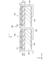
- FIG. 2 is a cross-sectional view taken along line F2-F2 in FIG. 1;
- FIG. 2 is an equivalent circuit diagram of the top cell module in the tandem solar cell of the first embodiment;
- FIG. 2 is a back view showing an example of the tandem solar cell of the first embodiment;
- FIG. 2 is a cross-sectional view taken along line F7-F7 in FIG. 1;
- FIG. 2 is a back view showing an example of a back-contact solar cell used in the tandem solar cell of the first embodiment;
- FIG. 8B is a cross-sectional view taken along line F8B-F8B in FIG.
- FIG. 8A; 4 is an equivalent circuit diagram of the bottom cell module in the tandem solar cell of the first embodiment;
- FIG. The top view which shows the example of the tandem solar cell of a comparative example.
- FIG. 12 is a perspective view of an F12 portion in FIG. 11; The perspective view of the F13 part in FIG.
- FIG. 20 is a back view showing an example of a tandem solar cell according to an eighth modified example
- FIG. 2 is a cross-sectional view showing an example of a crystalline silicon solar cell that can be used in each embodiment and each modification;
- tandem solar cell of the embodiment will be described below with reference to the drawings.
- the same reference numerals are given to the same or corresponding configurations unless otherwise specified.
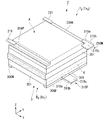
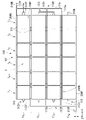
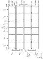
- FIG. 1 is a plan view showing an example of the tandem solar cell of the first embodiment.
- FIG. 2 is a cross-sectional view taken along line F2-F2 in FIG. 3 is a perspective view of the F3 section in FIG. 1.
- FIG. 4 is a perspective view of the F4 portion in FIG. 1.
- the tandem solar cell 1 shown in FIG. 1 generates electricity by photoelectrically converting incident light incident from the front side to the back side of the paper.
- viewing the tandem solar cell 1 along the normal to the incident surface of the incident light in the tandem solar cell 1 is referred to as planar view.
- the plan view is the same as the view from the thickness direction of the top cell Ti , which will be described later.
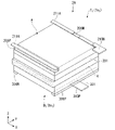
- the tandem solar cell 1 has a top cell module 2 and a bottom cell module 3 .
- the top cell module 2 and the bottom cell module 3 are mechanically joined together in the thickness direction with a light-transmissive insulating layer 4 interposed therebetween. are separated from each other.
- the insulating layer 4 is formed by applying a transparent resin adhesive to the surface of a transparent base material.
- the top cell module 2 has m (where m is an integer equal to or greater than 2) top cell strings Ts 1 , . . . , Ts m .
- Each of the top cell strings Ts 1 .
- any one of the top cells T 1 .
- the totality of the top cells T 1 . It may be described.
- the rated outputs of the top cells T 1 -T n forming the top cell string Tsj are more preferably the same, but they do not have to be the same.
- the rated output is the amount of power generated by the top cell when AM1.5 sunlight (1 kW/m 2 ) is vertically incident, that is, the product of the output voltage and the output current.
- the rated outputs of the top cells T 1 -T n in the top cell string Ts j are the same.
- the rated outputs of the top cells T i with the same subscript i may or may not be the same.
- top cells T i are arranged in the horizontal direction of the figure and electrically connected to each other to form a top cell string Ts j .
- the top cell strings Tsj are arranged adjacent to each other in their respective longitudinal directions (horizontal direction in the drawing). Therefore, the top cells T i in the top cell module 2 are arranged in an n ⁇ m rectangular grid as a whole.
- n and m are not limited to this.
- each top cell string Tsj is called the X-axis direction
- the arrangement direction (vertical direction in the figure) of each top cell string Tsj is called the Y-axis direction.
- the thickness direction of the tandem solar cell 1 is called the Z-axis direction.
- the positive direction of the X-axis direction (X-axis positive direction) is the direction in which the subscript i of the top cell T i is arranged in descending order.
- the positive direction of the Y-axis (positive Y-axis direction) is the direction in which the subscript j of the top cell string Ts j is arranged in descending order.
- the positive direction of the Z-axis direction is the direction from the bottom cell module 3 toward the top cell module 2 in the normal direction of the incident surface of the top cell module 2 .
- the X-axis negative direction, the Y-axis negative direction, and the Z-axis negative direction are directions opposite to the X-axis positive direction, the Y-axis positive direction, and the Z-axis positive direction, respectively.
- the Z-axis direction is a vertical direction in which the Z-axis positive direction is upward and the Z-axis negative direction is downward.
- up and down mean up and down in the Z-axis direction.
- Top cell T2 has a substrate 201 and a series array cell A.
- the substrate 201 is a plate member forming the lower layer of the top cell T2.
- the material of the substrate 201 is not particularly limited as long as it has optical transparency. A higher transmittance of the substrate 201 is more preferable.
- the material of the substrate 201 is more preferably glass.
- the material of the substrate 201 is acrylic, polyimide, polycarbonate, polyethylene terephthalate (PET), polypropylene (PP), fluorine resin (polytetrafluoroethylene (PTFE), perfluoroethylene propene copolymer (FEP), ethylenetetrafluoroethylene copolymer (ETFE), polychlorotrifluoroethylene (PCTFE), perfluoroalkoxyalkane (PFA), etc.), transparent resins such as polyarylate, polysulfone, polyethersulfone and polyetherimide, soda lime glass, white plate glass, Inorganic materials such as chemically strengthened glass and quartz can be used.
- the substrate 201 may be laminated with the materials listed above.
- the substrate 201 is mechanically joined to the surface of the insulating layer 4 in the positive direction of the Z-axis in such a posture that the thickness direction of the substrate 201 coincides with the Z-axis direction.
- the substrate 201 defines the outline of the top cell T2 in plan view.
- the outside of the top cell T2 in plan view refers to a region outside the outer periphery of the substrate 201 in plan view.
- the planar shape of the substrate 201 is a rectangle having two sides extending in the X-axis direction and two sides extending in the Y-axis direction. be.
- the serial array cell A is a photovoltaic cell having optical transparency in the thickness direction.
- the serial array cell A is stacked on the surface 201a of the substrate 201 opposite to the insulating layer 4 (positive direction of the Z-axis).
- the serial array cell A has a negative electrode portion A 0 , k (k is an integer equal to or greater than 2) unit cells A 1 , . . . , A k , and a positive electrode portion A k+1 .
- the number k of the unit cells A 1 , . . . , A k is not particularly limited as long as it is 2 or more. For example, k may be 25.
- a k absorb part of the incident light L incident from above the top cell module 2 to generate power.
- the incident light L is depicted as vertically incident on the top cell module 2, but the incident angle of the incident light L is not limited to being vertical.
- the unit cells A 1 , . . . , A k are connected in series between the negative electrode section A 0 and the positive electrode section A k+1 . Each of the negative electrode portion A 0 , the unit cells A 1 , . The negative electrode portion A 0 , the unit cells A 1 , . arranged in this order.
- a lower layer portion of the series array cell A stacked on the front surface 201 a is formed of a rear transparent electrode layer 202 .
- the back transparent electrode layer 202 is formed of a conductive film having optical transparency.
- the back transparent electrode layer 202 preferably includes one or more layers of oxide transparent conductive films.
- the kind of oxide transparent conductive film is not particularly limited.
- the oxide transparent conductive film indium tin oxide (ITO), aluminum-doped zinc oxide (AZO), boron-doped zinc oxide (BZO), gallium-doped Gallium-doped Zinc Oxide (GZO), doped tin oxide, Titanium-doped Indium Oxide (ITiO), Indium Zinc Oxide (IZO) and Indium Gallium Zinc Oxide (IZO).
- Semiconductor conductive films such as Gallium Zinc Oxide (IGZO) and hydrogen-doped Indium Oxide (IOH).
- the oxide transparent conductive film may be a laminated film having a plurality of films. A dopant to the film such as tin oxide is not particularly limited.
- dopants include one or more elements selected from the group consisting of In, Si, Ge, Ti, Cu, Sb, Nb, Ta, W, Mo, F, and Cl.
- the back transparent electrode layer 202 is a tin oxide film doped with one or more elements selected from the group consisting of In, Si, Ge, Ti, Cu, Sb, Nb, Ta, W, Mo, F, and Cl. preferably included.
- the doped tin oxide film at least one element selected from the group consisting of In, Si, Ge, Ti, Cu, Sb, Nb, Ta, W, Mo, F, and Cl is included in the tin oxide film. It is preferably contained in an amount of 10 atomic % or less with respect to the tin contained.
- the back transparent electrode layer 202 is a dot-like, line-like or mesh-like electrode between the oxide transparent conductive film and the substrate 201 or between the oxide transparent conductive film and the p-Cu 2 O layer 203 described later. preferably included.
- the dot-shaped, line-shaped or mesh-shaped electrodes preferably contain one or more materials selected from the group consisting of metals, alloys, graphene, conductive nitrides and conductive oxides.
- a dot-shaped, line-shaped or mesh-shaped electrode is effective when the electric resistance of the oxide transparent conductive film is high and the efficiency is lowered due to a voltage drop by itself.
- the metal used for the dot-shaped, line-shaped or mesh-shaped electrodes preferably has an aperture ratio of 95% or more with respect to the oxide transparent conductive film.
- Metals used for the dot-shaped, line-shaped or mesh-shaped electrodes are not particularly limited, but examples thereof include Mo, Au, Cu, Ag, Al, Ta and W.
- the film thickness of the metal film is not particularly limited as long as the required light transmittance is ensured by the openings and the electrical resistance is lower than that of the oxide transparent conductive film. .
- the back transparent electrode layer 202 is patterned into respective shapes of the negative electrode portion A0 and the unit cells A1, . . . , Ak in plan view. Therefore, the back transparent electrode layer 202 forms (k+1) strip-shaped conductive patterns separated from each other in the Y-axis direction.
- the back transparent electrode layer 202 forming the lower layer portion of the unit cell Ak protrudes in the Y-axis negative direction from the upper layer portion of the unit cell Ak in plan view.
- a positive electrode portion Ak + 1 is formed on the rear transparent electrode layer 202 projecting in the Y-axis negative direction from the upper layer portion of the unit cell Ak.
- the negative electrode portion A0 has a negative electrode 206N laminated on the rear transparent electrode layer 202 forming the lower layer portion of the negative electrode portion A0 .
- the negative electrode 206 ⁇ /b>N is arranged to cover the entire rear transparent electrode layer 202 forming the lower layer of the negative electrode portion A 0 and is electrically connected to the rear transparent electrode layer 202 .
- the negative electrode 206N is made of a conductive material such as a metal film.
- the material of the metal film is not particularly limited.
- the negative electrode 206N may be formed of a conductive film similar to the surface transparent electrode layer 205, which will be described later.
- Mo, Au, Cu, Ag, Al, Ta, W, etc. are mentioned as a material of the metal film used for the negative electrode 206N. It is also preferable to use a conductive metal paste as the metal film.
- Each of the unit cells A 1 , . . . , A k is, for example, a cuprous oxide (Cu 2 O) solar cell.
- Each of the unit cells A 1 , . are stacked in this order. However, such a configuration is an example.
- an antireflection film may be formed on the upper surface of the n-compound layer 204 for the purpose of increasing the amount of incident light L incident on the p-Cu 2 O layer 203 and the n-compound layer 204, which are power generation layers.
- the types of unit cells A 1 , . . . , A k are not limited to cuprous oxide solar cells. For example, the types of unit cells A 1 , .
- the p-Cu 2 O layer 203 is a p-type semiconductor that generates holes and electrons by incident light L, and is formed of a thin film of p-type cuprous oxide.
- the n-compound layer 204 is an n-type semiconductor that transports electrons generated in the p-Cu 2 O layer 203 by the incident light L to the surface transparent electrode layer 205, and is laminated on the upper surface of the p-Cu 2 O layer 203. there is The n-compound layer 204 forms a hetero pn junction with the p-Cu 2 O layer 203 .
- the n-compound layer 204 is not particularly limited, it is preferably an oxide semiconductor layer containing Ga and containing a compound containing Ga as a main component.
- the n-compound layer 204 may be a mixture of an oxide containing Ga as a main component and another oxide, or an oxide containing Ga as a main component and doped with another element. , an oxide mainly composed of Ga doped with other elements and other oxides may be mixed.
- the n-compound layer 204 may be a single layer or multiple layers.
- Ga is preferably 50 atomic % or more.
- the metal element contained in the n-compound layer 204 may be inclined from the p-Cu 2 O layer 203 side toward the surface transparent electrode layer 205 side.
- the n-compound layer 204 is a group consisting of Sn, Sb, Ag, Li, Na, K, Cs, Rb, Al, In, Zn, Mg, Si, Ge, N, B, Ti, Hf, Zr, and Ca. It is preferable that 90 wt % or more of an oxide of one or more selected elements and an oxide of Ga be included.
- a surface transparent electrode layer 205 is laminated on the upper surface of the n-compound layer 204 .
- the front transparent electrode layer 205 is made of a conductive film having optical transparency.
- the front transparent electrode layer 205 may be made of the same material as the back transparent electrode layer 202 .
- each conductive path 208 is schematically drawn as a line, but is not limited to a linear wiring.
- each conductive path 208 is formed by forming the n-compound layer 204 on the p-Cu 2 O layer and then performing grooving to expose the back transparent electrode layer 202 at that location, followed by the front transparent electrode layer.
- the rear transparent electrode layer 202 and the front transparent electrode layer 205 may be electrically connected through the groove.
- the surface transparent electrode layer 205 in the unit cell A1 is electrically connected to the negative electrode 206N of the negative electrode portion A0 through a conductive path 208. As shown in FIG.
- the positive electrode portion A k+1 has a positive electrode 206P on the back transparent electrode layer 202 forming the lower layer portion of the unit cell A k .
- the positive electrode 206P is laminated on the rear transparent electrode layer 202 forming the lower layer of the unit cell Ak , extends in the X-axis direction, and is electrically connected to the rear transparent electrode layer 202. As shown in FIG.
- each surface transparent electrode layer 205 of the unit cells A 1 , . 2 surface.
- the top surfaces of the negative electrode 206N and the positive electrode 206P are drawn lower than the plane Is, but the height of each top surface is not limited to this.
- one or both of the upper surface of the negative electrode 206N and the upper surface of the positive electrode 206P may be positioned at a height equal to or higher than the plane Is.
- the negative electrode 206N and the positive electrode 206P in each top cell T i are provided on the surface side where the incident light L is incident.
- the negative electrode 206N and the positive electrode 206P in each top cell T i are examples of first cell electrodes provided on the surface opposite to the surface facing each bottom cell B i .
- Each top cell T i in the top cell module 2 has the same configuration as the top cell T 2 described above. As shown in FIG. 1, the top cells T i are arranged in a rectangular lattice in the X-axis direction and the Y-axis direction, with the negative electrode 206N located in the Y-axis positive direction and the positive electrode 206P located in the Y-axis negative direction. ing. Note that the detailed structure of the series array cell A is omitted in FIG. 1 for the sake of simplicity. In each top cell string Tsj , top cells T i adjacent to each other in the X-axis direction are electrically connected by first cell connects 211 .
- the first cell connect 211 is a conductor that electrically connects the negative electrodes 206N or the positive electrodes 206P.
- the configuration of the first cell connect 211 is not particularly limited as long as the negative electrodes 206N and the positive electrodes 206P can be electrically connected to each other.
- the first cell connect 211 is a ribbon-shaped conductor having a width shorter than the length of the negative electrode 206N and the positive electrode 206P and equal to or less than the lateral width (the width in the Y-axis direction). Note that the detailed structure of the series array cell A is omitted in FIG. 3 for the sake of simplicity.
- the first cell connect 211 is arranged over the upper sides of the negative electrodes 206N that are adjacent to each other in the X-axis direction, and is joined to each negative electrode 206N by, for example, a conductive paste or a solder material.
- the first cell connect 211 is an example of a short connect that connects adjacent top cells, but the shape of the first cell connect 211 is not limited to this.
- a single long cell connect that is connected to each negative electrode 206N over the entire plurality of cells forming one string may be used.
- the first cell connect 211 is arranged across the upper side of the positive electrodes 206P that are adjacent to each other in the X-axis direction, and is joined to each positive electrode 206P by, for example, a conductive paste or a solder material. .
- the first cell connect 211 that connects the positive electrodes 206P is connected to each positive electrode 206P across the entire plurality of cells that constitute one string. A single long cell connect may be used.
- Each negative electrode 206N and each positive electrode 206P of each top cell string Tsj electrically connected by the first cell connect 211 are provided on the surface side where the incident light L is incident.
- Each negative electrode 206N and each positive electrode 206P of each top cell string Tsj electrically connected by the first cell connect 211 are arranged on the surface opposite to the surface facing each bottom cell string Bsj , which will be described later. It is an example of the provided first electrode portion.
- the positive electrode 206P and the negative electrode 206N at the ends (top cells Tn ) of the top cell strings Ts1 and Ts2 in the negative direction of the X axis are electrically connected to each other by the first string connect 212. It is connected to the.
- a first string connect 212 electrically connects the positive electrode 206P and the negative electrode 206N of the ends (top cell T 1 ) of the top cell strings Ts 2 and Ts 3 in the positive direction of the X-axis to each other.
- the positive electrode 206P and the negative electrode 206N of the top cell strings Ts 3 and Ts 4 in the X-axis negative direction (top cell T n ) are electrically connected to each other by a first string connect 212 . Therefore, the first string connect 212 electrically connects the top cell strings Ts j that are different from each other in a plan view among the top cell strings Ts j at the respective first electrode portions.
- each first string connect 212 is not particularly limited as long as it can electrically connect the positive electrode 206P and the negative electrode 206N.
- each first string connect 212 has the same shape.
- Each first string connect 212 is formed in a U shape opening in the Y-axis direction in a plan view, and is a ribbon-shaped conductor having a width equal to or smaller than the lateral width of the negative electrode 206N and the positive electrode 206P.
- the first string connect 212 includes a connection portion 212a connected to the positive electrode 206P and the negative electrode 206N from above, and a first extension portion extending outside the top cell module 2 in plan view. 212b and .
- connection portion 212a is arranged above the positive electrode 206P and the negative electrode 206N that are adjacent to each other in the Y-axis direction. Each connection portion 212a is joined to the positive electrode 206P and the negative electrode 206N by, for example, a conductive paste or a solder material.
- the first extending portion 212b extends from each connecting portion 212a in the positive direction of the X-axis, and along a path that bends or curves in a U-shape in plan view, each top cell T1 defined by the outer shape of the substrate 201 extends outside the outline of the The extension length in the X-axis direction of the first extension portion 212b is, for example, d1.
- each connecting portion 212a and the first extending portion 212b of the first string connect 212 are formed of a single member that is U-shaped in plan view. It is not limited to this.
- the first string connect 212 may be configured by joining a plurality of conductors together.
- the first string connect 212 may have a first conductor similar to the first cell connect 211 and a second conductor joining the first conductors. Each first conductor is joined to the upper side of a positive electrode 206P and a negative electrode 206N.
- the second conductor As the second conductor, a ribbon-shaped conductor that joins the first conductors in the Y-axis direction, or a U-shaped tip in a plan view similar to the first extension 212b and having a U-shaped tip on each first conductor Bonded conductors, etc. can be used.
- the first string connect 212 has a U-shape in plan view in which the first conductors and the second conductors are joined.
- Each first conductor on positive electrode 206P and negative electrode 206N form a connection similar to connection 212a.
- Each first conductor and second conductor located outside the outline of each top cell T1 form a first extension similar to first extension 212b.
- a first negative terminal 210N is connected from above to the end of the negative electrode 206N of the top cell string Ts1 in the positive direction of the X axis.
- the configuration of the first negative electrode terminal 210N is not particularly limited as long as it can be electrically connected to the negative electrode 206N and can be connected to an external wiring for extracting the output of the positive electrode of the top cell module 2 to the outside.
- the first negative terminal 210N has a connecting portion 210a connected to the negative electrode 206N from above, and a third extending portion 210b extending outside the top cell module 2 in plan view.
- the connecting portion 210a has a width equal to or less than the lateral width of the negative electrode 206N in the Y-axis direction, and a width less than the longitudinal width of the negative electrode 206N in the X-axis direction.
- a terminal electrode 210c having a width wider than that of the connecting portion 210a is drawn for the purpose of connecting an external wiring at the distal end portion of the third extending portion 210b in the extending direction. If the connection can be reliably performed, the terminal electrode 210c and the connection portion 210a may have the same width in the Y-axis direction.
- the first negative terminal 210N may be made of the same material as the first cell connect 211, such as a ribbon-like metal wire.
- a first positive terminal 210P is connected from above to the end of the positive electrode 206P of the top cell string Ts4 in the positive direction of the X axis.
- the configuration of the first positive electrode terminal 210P is not particularly limited as long as it can be electrically connected to the positive electrode 206P and can be connected to an external wiring for extracting the output of the negative electrode of the top cell module 2 to the outside.
- the first positive terminal 210P has a connecting portion 210a connected to the positive electrode 206P from above, and a third extending portion 210b extending outside the top cell module 2 in plan view.
- the connection portion 210a of the first positive electrode terminal 210P has a width equal to or less than the lateral width of the positive electrode 206P.
- a terminal electrode 210c similar to that of the first negative terminal 210N is drawn at the tip of the third extending portion 210b of the first positive terminal 210P in the extending direction. If it can be ensured, the terminal electrode 210c and the connection portion 210a may have the same width in the Y-axis direction.
- the first positive terminal 210P may be made of the same material as the first cell connect 211, such as a ribbon-shaped metal wire.
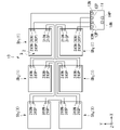
- FIG. 5 is an equivalent circuit diagram of the top cell module in the tandem solar cell of the first embodiment.
- the top cells T 1 -T n in each top cell string Ts j are connected in parallel by the first cell connect 211 .
- the top cell strings Ts 1 -Ts m are connected in series by a first string connect 212 .
- the top cell module 2 has a circuit configuration (n parallel m series) in which m sets of n top cells Ti connected in parallel are connected in series.
- Each negative electrode 206N in the top cell string Ts1 is the positive electrode of the top cell module2.
- Each positive electrode 206 P in the top cell string Ts m is the negative electrode of the top cell module 2 .
- the first negative electrode terminal 210N is connected to the negative electrode 206N of the top cell T1 among the positive electrodes of the top cell module 2 .
- the first positive electrode terminal 210P is connected to the positive electrode 206P of the top cell T1 among the negative electrodes of the top cell module 2 .
- FIG. 6 is a back view showing an example of the tandem solar cell of the first embodiment.
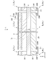
- FIG. 7 is a cross-sectional view taken along line F7-F7 in FIG.
- the bottom cell module 3 has m (where m is an integer equal to or greater than 2) bottom cell strings Bs 1 , . . . , Bs m .
- the numbers n and m in the bottom cell module 3 may be different from the numbers n and m in the top cell module 2, but below, an example will be described that is equal to the numbers n and m in the top cell module 2. do.
- any one of the bottom cells B 1 when any one of the bottom cells B 1 , .
- the totality of the bottom cells B 1 when any one of the bottom cell strings Bs 1 , .
- the bottom cells B 1 -B n constituting the bottom cell string Bs j have the same rated output, but it does not have to be the same.
- the bottom cells B 1 -B n in one bottom cell string Bs j have the same rated output.
- the rated outputs of the bottom cells B i with the same suffix i included therein may or may not be the same.
- the bottom cell strings Bs j with different subscripts j have the same rated output of each bottom cell B i . That is, in the following description, the rated output of each bottom cell B i and the rated output of each bottom cell string Bs j are the same.
- each bottom cell B i in the bottom cell module 3 has the same external shape and external size in plan view as the external shape and external size of each top cell T i .
- Each bottom cell B i overlaps the top cell T i corresponding to the subscript i in plan view. Therefore, the bottom cell string Bs j overlaps with the top cell string Ts j having the same subscript j in the thickness direction. When overlapping, the top cell string Ts j and the bottom cell string Bs j need not completely overlap.
- the outer shape and outer size of the bottom cell B i may differ from the top cell T i .
- the bottom cell B i and the top cell T i may be shifted in at least one of the X-axis direction and the Y-axis direction.
- the bottom cell B 2 is a solar cell that generates power by receiving incident light L′ that has passed through the top cell T 2 and the insulating layer 4 out of the incident light L.
- the type of the bottom cell B2 is not particularly limited as long as it can generate power with light of a wavelength that is difficult to be absorbed by the top cell T2. For example, since long-wavelength light can easily reach the deep part of the medium, it is more preferable that the top cell T2 can generate power with the short - wavelength component and the bottom cell B2 can generate power with the long - wavelength component.
- a cuprous oxide solar cell is suitable as the top cell T2 because it absorbs short wavelength light and easily transmits long wavelength light.
- the top cell T2 is a cuprous oxide solar cell, as the bottom cell B2
- Bottom cell B2 is, for example, a back contact solar cell.
- bottom cell B2 has a cell body 301, a positive electrode 306P and a negative electrode 306N.
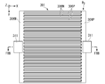
- FIG. 8A is a back view showing an example of a back-contact solar cell.
- FIG. 8B is a cross-sectional view along line F8B-F8B in FIG. 8A.
- the arrangement of the cell main body 301 shown in FIG. 8A is an example when used for the bottom cell B2 of the bottom cell string Bs1.
- Line F8B-F8B in FIG. 8A corresponds to line F7-F7 in FIG. As shown in FIG.
- the cell body 301 has an antireflection film 302, an n-type semiconductor 303, and a diffusion layer 304 laminated in this order in the Z-axis negative direction.
- the configuration shown in FIG. 8B is an example.
- a protective film, a sealing material, or the like may be added to the cell body 301 as appropriate.
- the antireflection film 302 is bonded to the bottom surface of the insulating layer 4 .
- the antireflection film 302 is provided on the upper surface of the cell body 301 to suppress reflection of the incident light L′ transmitted through the top cell module 2 and the insulating layer 4 .
- the n-type semiconductor 303 receives the incident light L' and generates carriers.
- the n-type semiconductor 303 is an n-type crystalline Si substrate.
- p+ diffusion layers 304P and n+ diffusion layers 304N are alternately arranged in the Y-axis direction.
- each p+ diffusion layer 304P in the X-axis positive direction is connected to the p+ diffusion layer 304P extending in the Y-axis direction.
- the end of each n+ diffusion layer 304N in the negative direction of the X-axis is connected to the n+ diffusion layer 304N extending in the Y-axis direction.
- a positive electrode 306P is joined to the lower surface of each p+ diffusion layer 304P.
- a negative electrode 306N is joined to the lower surface of each n+ diffusion layer 304N.
- the positive electrode 306P viewed from the Z-axis positive direction forms a comb-like conductive pattern similar to the p+ diffusion layer 304P.
- the positive electrode 306P is used as a positive electrode for taking out the positive voltage generated in the cell body 301.
- the end portion of the positive electrode 306P in the positive direction of the X-axis is a strip-shaped conductive portion that is long in the Y-axis direction.
- the end of the positive electrode 306P in the X-axis positive direction is used for electrical connection with the bottom cell B1.
- the negative electrode 306N viewed from the Z-axis positive direction forms a comb-shaped conductive pattern similar to the n+ diffusion layer 304N.
- the comb teeth of the negative electrode 306N enter the recesses of the comb teeth of the positive electrode 306P.
- the negative electrode 306N is used as a negative electrode for taking out the negative voltage generated in the cell body 301.
- the end portion of the negative electrode 306N in the negative direction of the X-axis is a strip-shaped conductive portion that is long in the Y-axis direction.
- the end of the negative electrode 306N in the negative direction of the X axis is used for electrical connection with the bottom cell B3.
- the positive electrode 306P and the negative electrode 306N are provided on the back side of the cell body 301 of the bottom cell B2, which is opposite to the front side on which the incident light L' is incident.
- the positive electrode 306P and the negative electrode 306N are examples of second cell electrodes provided on the surface opposite to the surface facing each top cell Ti.
- a positive electrode 306P long in the Y-axis direction and a positive electrode 306P at the end in the X-axis direction and a A negative electrode 306N that is long in the Y-axis direction is described in the section.
- the positive electrode 306P and the negative electrode 306N respectively mean the portion of the positive electrode 306P and the portion of the negative electrode 306N extending in the Y-axis direction at the ends in the X-axis direction.
- the cell body 301 defines the outline of the bottom cell B2 in plan view.
- the outer side of the bottom cell B2 in plan view refers to a region outside the outer peripheral portion of the cell body 301 in plan view. As shown in the example of the bottom cell B1 in the bottom cell string Bs1 in FIG. be.
- Each bottom cell B i in the bottom cell module 3 has the same configuration as the bottom cell B 2 described above.
- each bottom cell B i is arranged in the X-axis direction with the positive electrode 306P positioned in the X-axis positive direction and the negative electrode 306N positioned in the X-axis negative direction. placed side by side.
- the bottom cells B i are arranged side by side in the X-axis direction with the positive electrode 306P positioned in the negative direction of the X-axis and the negative electrode 306N positioned in the positive direction of the X-axis.
- each bottom cell string Bsj the bottom cells Bi adjacent to each other in the X-axis direction are electrically connected by a second cell connect 311, respectively.
- the second cell connect 311 is a conductor that electrically connects the negative electrode 306N and the positive electrode 306P that are adjacent to each other in the bottom cells Bi that are adjacent to each other in the X-axis direction.
- the configuration of the second cell connect 311 is not particularly limited as long as it can electrically connect the negative electrode 306N and the positive electrode 306P.
- the second cell connect 311 is a ribbon-shaped conductor covering the positive electrode 306P and the negative electrode 306N from below and extending in the X-axis direction.
- the width of the second cell connect 311 in the Y-axis direction is not particularly limited. In the example shown in FIG. 6, the length is about one-fifth of the length of the positive electrode 306P and the negative electrode 306N, but this length is not particularly limited either.
- the position of the second cell connect 311 in the Y-axis direction is not particularly limited, but in the example shown in FIG. 6, it is the central portion of the positive electrode 306P and the negative electrode 306N in the Y-axis direction.
- the center line in the Y-axis direction of the second cell connect 311 is located at a position that bisects the width y0 in the Y-axis direction of the outline of the bottom cell Bi .
- the second cell connect 311 is joined to the positive electrode 306P and the negative electrode 306N by conductive paste, soldering material, or the like.
- Each positive electrode 306P and each negative electrode 306N of each bottom cell string Bsj electrically connected by the second cell connect 311 are provided on the back side where the incident light L′ which is part of the incident light L is incident. It is
- Each positive electrode 306P and each negative electrode 306N of each bottom cell string Bsj is an example of a second electrode portion provided on the side opposite to the side facing the top cell string Tsj .
- the negative electrode 306N of the X - axis negative end (bottom cell Bn) of the bottom cell string Bs1 is connected by the second string connect 312 to the X-axis negative end of the bottom cell string Bs2. It is electrically connected to the positive electrode 306P of the part.
- the negative electrode 306N at the end in the positive X-axis direction (bottom cell B 1 ) in the bottom cell string Bs 2 is electrically connected to the positive electrode 306P at the positive end in the X-axis direction in the bottom cell string Bs 3 by the second string connect 312 . properly connected.
- the negative electrode 306N at the end of the bottom cell string Bs3 in the negative direction of the X axis is electrically connected to the positive electrode 306P at the end of the bottom cell string Bs4 in the negative direction of the X axis by a second string connect 312.
- each second string connect 312 is not particularly limited as long as it can electrically connect the negative electrode 306N and the positive electrode 306P. In the example shown in FIG. 6, all the second string connects 312 have the same shape.
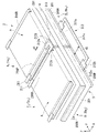
- Each second string connect 312 is a U-shaped ribbon-like conductor that opens in the X-axis direction in a plan view. As shown in FIG. 4, the second string connect 312 includes a connection portion 312a that connects to the negative electrode 306N and the positive electrode 306P from below, and a second extension that extends outside the bottom cell module 3 in plan view. and a portion 312b.
- Each connection portion 312a is arranged below the negative electrode 306N and the positive electrode 306P that are adjacent to each other in the Y-axis direction, and is joined to the negative electrode 306N and the positive electrode 306P by, for example, a conductive paste or a solder material. It is The arrangement position of each connecting portion 312a in the Y-axis direction is not particularly limited. In the example shown in FIG. 4, each connecting portion 312a is arranged at the central portion in the Y-axis direction of the negative electrode 306N and the positive electrode 306P. The width of each connecting portion 312a in the Y-axis direction is shorter than the length of the negative electrode 306N and the positive electrode 306P in the Y-axis direction.
- each connecting portion 312a in the Y-axis direction is, like the width of the second cell connect 311, approximately one-fifth the length of the positive electrode 306P and the negative electrode 306N.
- the arrangement position in the Y-axis direction of each connection portion 312a is not particularly limited.
- the center line in the Y-axis direction of each connection portion 312a is located at a position that bisects the width y0 of the outer shape of the bottom cell Bi in the Y-axis direction, like the second cell connect 311 .
- the second extending portion 312b extends from each connecting portion 212a in the positive direction of the X-axis, and extends along a path that bends or curves in a U-shape in a plan view. It extends outside the outline of each defined bottom cell B1.
- the width of the second extending portion 312b is not particularly limited. In the example shown in FIG. 4, after extending in the positive direction of the X-axis with the same width as the connecting portion 312a, the width is reduced to form a path that bends or curves with substantially the same width. As shown in FIGS.
- the second extensions 312b sandwich the first extensions 212b of the first string connectors 212 from outside the top cell module 2 and the bottom cell module 3. .
- the second extensions 312b and the first extensions 212b do not overlap and are separated from each other.
- the length of the second extension 312b is preferably shorter than the length of the first extension 212b.
- Each second extension 312b may surround the first extension 212b of the first string connect 212 from the outside of the top cell module 2 and the bottom cell module 3 in plan view. For example, in the example shown in FIG.
- a linear portion 312c extending in the Y - axis direction outside each bottom cell B1 is formed at the most distal end of the second extending portion 312b in the extending direction.
- a gap having a width d2 in the X-axis direction larger than the extension length d1 of the first extension portion 212b is formed.
- each connecting portion 312a and the second extending portion 312b of the second string connect 312 are formed of a single member that is U-shaped in plan view. It is not limited to this.
- the second string connect 312 may be configured by joining a plurality of conductors together.
- the second string connect 312 may have a first conductor similar to the second cell connect 311 and a second conductor joining the first conductors. Each first conductor is joined to the underside of a positive electrode 306P and a negative electrode 306N.
- the second conductor As the second conductor, a ribbon-shaped conductor that joins the first conductors in the Y-axis direction, or a U-shaped tip in a plan view similar to the linear portion 312c is joined to each first conductor. conductors, etc. can be used.
- the second string connect 312 has a U-shape in plan view in which the first conductors and the second conductors are joined.
- Each first conductor on positive electrode 306P and negative electrode 306N form a connection similar to connection 312a.
- Each first conductor and second conductor located outside the outline of each bottom cell B1 form a second extension similar to the second extension 312b.
- such a configuration of the second string connect 312 can be formed as follows.
- the positive electrode 306P and the negative electrode 306N are attached such that the second cell connect 311 extends from above the positive electrode 306P and the negative electrode 306N toward the outside of the bottom cell B1.
- a second conductor corresponding to the linear portion 312 c formed of a ribbon-shaped conductor is coupled to each second cell connect 311 .
- the shape of the second conductor in plan view is not limited to the U shape in plan view like the second string connect 312 .
- the shape of the second conductor in plan view does not matter as long as the first conductors formed by the second cell connect 311 can be connected to each other on the outside of each bottom cell B1 .
- a second positive electrode terminal 310P is connected from below to the positive electrode 306P of the bottom cell B1 in the bottom cell string Bs1.
- the configuration of the second positive electrode terminal 310P is not particularly limited as long as it can be electrically connected to the positive electrode 306P and can be connected to an external wiring for extracting the output of the positive electrode of the bottom cell module 3 to the outside.
- the second positive electrode terminal 310P has a connecting portion 310a connected to the positive electrode 306P from below, and a third extending portion 310b extending outside the bottom cell module 3 in plan view.
- connection portion 310a has a width equal to or less than the lateral width of the positive electrode 306P in the X-axis direction, and a width equal to or less than the longitudinal width of the positive electrode 306P in the Y-axis direction.
- the width of the connecting portion 310a in the Y-axis direction may be approximately the same as the width of the second cell connect 311 in the Y-axis direction.
- a terminal electrode 310c is formed at the tip of the third extending portion 310b in the extending direction for the purpose of connecting an external wiring.
- the extension length in the X-axis direction and the width in the Y-axis direction of the third extension portion 310b are not particularly limited. In the example shown in FIG.
- the extension length is equal to the extension length of the third extension portion 210b
- the width in the Y-axis direction is equal to the width of the connection portion 310a.
- the second positive terminal 310P is made of the same conductor as the first negative terminal 210N.
- the arrangement position of the second positive terminal 310P in the Y-axis direction is not particularly limited as long as it does not overlap the first negative terminal 210N, the first string connect 212, and the second string connect 312 in plan view.
- the second positive electrode terminal 310P is provided at the same position as the second cell connect 311 in the bottom cell B1 provided with the second positive electrode terminal 310P in the Y-axis direction.
- a second negative electrode terminal 310N is connected from below to the negative electrode 306N of the bottom cell Bi in the bottom cell string Bs4 .
- the configuration of the second negative electrode terminal 310N is not particularly limited as long as it can be electrically connected to the negative electrode 306N and can be connected to an external wiring for extracting the output of the negative electrode of the bottom cell module 3 to the outside.
- the second negative terminal 310N has a connecting portion 310a connected to the negative electrode 306N from below, and a third extending portion 310b extending outside the bottom cell module 3 in plan view.
- the shape of the second negative terminal 310N may be different from that of the second positive terminal 310P, but in the example shown in FIG.
- a terminal electrode 310c similar to the second positive electrode terminal 310P is formed at the tip of the second negative electrode terminal 310N in the extending direction of the third extending portion 310b.
- the second negative terminal 310N is formed of a conductor such as a ribbon-shaped metal wire made of the same material as the second positive terminal 310P.
- the arrangement position of the second negative terminal 310N in the Y-axis direction is not particularly limited as long as it does not overlap the first positive terminal 210P, the first string connect 212, and the second string connect 312 in plan view.
- the second negative terminal 310N is provided at the same position as the second cell connect 311 in the bottom cell B1 provided with the second negative terminal 310N in the Y-axis direction.
- FIG. 9 is an equivalent circuit diagram of the bottom cell module in the tandem solar cell of the first embodiment.
- bottom cells B 1 -B n in each bottom cell string Bs j are connected in series by a second cell connect 311 .
- the bottom cell strings Bs 1 -Bs m are connected in series by a second string connect 312 .
- the bottom cell module 3 has a circuit configuration in which n ⁇ m bottom cells B i are connected in series.
- the positive electrode 306 P of bottom cell B 1 in bottom cell string B s 1 is the positive electrode of bottom cell module 3 .
- the negative electrode 306N of the bottom cell B1 in the bottom cell string Bsm is the negative electrode of the bottom cell module 3.
- the second positive electrode terminal 310P is connected to the positive electrode 306P that is the positive electrode of the bottom cell module 3 .
- the second negative electrode terminal 310N is connected to the negative electrode 306N, which is the negative electrode of the bottom cell module 3 .
- the tandem solar cell 1 includes the top cell module 2 that generates power from a portion of the incident light L, and the bottom cell module 3 that generates power from the incident light L′ transmitted through the top cell module 2 and the insulating layer 4. are stacked in the Z-axis direction.
- each bottom cell B i in the bottom cell module 3 is a back-contact type solar cell, loss of light quantity due to reflection and absorption of incident light L′ by cell contacts and electrodes is suppressed. As a result, the amount of power generated by the bottom cell module 3 can be increased.
- the top cell module 2 has a first negative terminal 210N and a first positive terminal 210P as external output terminals.
- the bottom cell module 3 has a second positive terminal 310P and a second negative terminal 310N as external output terminals. That is, the tandem solar cell 1 has four terminals that can independently take out the power output of each of the top cell module 2 and the bottom cell module 3 to the outside. It has a positive terminal 310P and a second negative terminal 310N.
- the top cell module and the bottom cell module in the tandem battery are electrically connected to each other in the tandem battery, and the power output of the tandem solar battery as a whole is taken out from two terminals, a positive terminal and a negative terminal.
- the connection form of the plurality of top cells and the connection form of the plurality of bottom cells need to be set so as to match the current ratio between the top cells and the bottom cells.
- the current ratio is the ratio of electric power generated by each of the top cell and the bottom cell when an assumed component of light is incident. For example, when the current ratio (top cell output current:bottom cell output current) is expressed as 1: ⁇ , ⁇ >1 because the bottom cell normally outputs more current.
- the power output of the top cell module 2 and the power output of the bottom cell module 3 can be obtained through independent circuits. It is not necessary to set the topology of B i to match the current ratio between the top cell T i and the bottom cell B i . Therefore, the connection form of each top cell T i and the connection form of each bottom cell B i can be freely set.
- the rated output voltage of the top cell T i is significantly higher than that of the bottom cell B i .
- the rated output voltage of top cell T i is about 40 times the rated output voltage of bottom cell B i .
- the rated output voltage means the voltage of the top cell T i generated between the first negative electrode terminal 210N and the first positive electrode terminal 210P when the sunlight of AM1.5 is vertically incident, and the bottom cell B i voltage generated between the terminal 310N and the second positive terminal 310P.
- the top cell T i produces an efficiency of 10% and the bottom cell B i produces an efficiency of 20%, thereby obtaining power generation with a total efficiency of 30%.
- the efficiency and power generation of the top cell module 2 are half of the efficiency and power generation of the bottom cell module 3, respectively.
- the fact that the rated output voltage is about 40 times higher means that the rated output current is about 1/80th lower than that of the bottom cell module 3. means that they are significantly different. Therefore, it is more preferable that the rated output voltage of the top cell module 2 be close to the rated voltage and rated current of the bottom cell module 3 .
- the rated output voltage of the top cell module 2 can be reduced by increasing the number of top cells Ti connected in parallel.
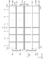
- FIG. 10 is a plan view showing an example of a tandem solar cell as a comparative example.
- the tandem solar cell 100 of the comparative example has a top cell module 102 instead of the top cell module 2 of the tandem solar cell 1 .
- the points different from the tandem solar cell 1 of the present embodiment will be mainly described.
- the top cell module 102 is the same as the top cell module 2 except that it has string connects 112P and 112N connecting the top cell strings Ts 1 -Ts 4 in parallel instead of the three first string connects 212 . In the top cell module 102, all top cells T i are connected in parallel.
- the string connect 112P electrically connects the positive electrodes of the top cell strings Tsj .
- the string connect 112P has a first linear portion 112a and a second linear portion 112b.
- the first linear portion 112a is a conductor connected to the positive electrode 206P of each top cell Tn and extending from each top cell T6 in the negative direction of the X axis in plan view.
- the second linear portion 112b is a linear conductor that conducts with the tip of each first linear portion 112a in the extending direction.
- the second linear portion 112b extends in the Y-axis direction at a position spaced apart in the negative X-axis direction from the end of each top cell T6 in the negative X - axis direction.
- the second linear portion 112b is positioned in the negative X-axis direction relative to the second string connect 312 arranged outside the bottom cell module 3 in the negative X-axis direction.
- a first positive electrode terminal 210P is connected to a connecting portion between the first linear portion 112a located most in the Y-axis negative direction and the end portion of the second linear portion 112b in the Y-axis positive direction.
- the first linear portion 112 a and the second linear portion 112 b are made of the same conductor as the first string connect 212 .
- the string connect 112N electrically connects the negative electrodes of the top cell strings Tsj .
- the string connect 112N has a first linear portion 112a and a second linear portion 112b.
- the first linear portion 112a of the string connect 112N is connected to the negative electrode 206N of each top cell T1, and extends in the positive direction of the X axis from each top cell T1 in plan view. is the same as the first linear portion 112a.
- the second linear portion 112b of the string connect 112N is a linear conductor that conducts with the tip of the first linear portion 112a of the string connect 112N in the extending direction.
- the second linear portion 112b of the string connect 112N extends in the Y-axis direction at a position spaced apart in the positive X-axis direction from the end of each top cell T1 in the positive X-axis direction. is the same as the second linear portion 112b of .
- the second linear portion 112b of the string connect 112N is positioned in the positive X-axis direction relative to the second string connects 312 arranged outside the bottom cell module 3 in the positive X-axis direction in plan view.
- the first negative terminal 210N is connected to the connecting portion between the first linear portion 112a positioned most in the Y-axis positive direction and the end portion of the second linear portion 112b in the Y-axis negative direction. is doing.
- the first linear portions 112a extend outward from at least the negative electrodes 206N and the positive electrodes 206P at both ends in the X-axis direction, Each of the first linear portions 112a at both ends must be electrically connected with the second linear portions 112b.
- the linear portion 312c of each second string connect 312 has a positional relationship that crosses the first linear portion 112a in plan view.
- the second positive electrode terminal 310P and the first linear portion 112a are positioned to intersect in plan view.
- the linear portion 312c, the wiring 113P, or the second positive terminal 310P which are in a positional relationship that intersects with the first linear portion 112a, are separated in the Z-axis direction, but the external force in the Z-axis direction is large. If touched, they may touch each other and short-circuit.
- the first string connects 212 are arranged in a positional relationship such that they do not intersect with the second string connects 312 in plan view. Therefore, it is not necessary to arrange an insulator for short-circuit prevention between the first string connect 212 and the second string connect 312 . The same applies to the relationship between the first string connect 212 and the second positive terminal 310P and the second negative terminal 310N. As a result, in the tandem solar cell 1, the outer configuration of the top cell module 2 and the bottom cell module 3 is simplified.
- the first string connect 212 and the second string connect 312 Each protective film can sandwich each first string connect 212 and each second string connect 312 without arranging an insulator for short circuit prevention between them.
- tandem solar cell 100 of the comparative example it is necessary to arrange the second linear portion 112b outside the linear portion 312c.
- the first string connect 212 can be arranged inside the linear portion 312c, so that the outer shape can be reduced at both ends in the X-axis direction.
- tandem solar cell 100 of the comparative example it is conceivable to dispose the second linear portion 112b inside the linear portion 312c.
- the second linear portion 112b intersects the linear portion 312c in more places in plan view, it is necessary to dispose the short-circuit-preventing frame in a wider range.
- tandem solar cell 1 of the present embodiment by appropriately setting the number n, the rated output voltage of the top cell string Tsj in which n top cells Ti are connected in parallel and the rated output voltage of the n bottom cells Bi can be brought close to the rated output voltage in each bottom cell string Bsj connected in series. As a result, a connection form that matches the current ratio between the top cell T i and the bottom cell B i is obtained.
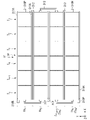
- FIG. 11 is a plan view showing an example of the tandem solar cell of the second embodiment.
- 12 is a perspective view of the F12 portion in FIG. 11.
- FIG. 13 is a perspective view of the F13 portion in FIG. 11.
- the tandem solar cell 1A of this embodiment has a top cell module 2A instead of the top cell module 2 in the tandem solar cell 1 of the first embodiment.
- the top cell module 2A has a first cell connect 211A instead of the first cell connect 211.
- FIG. A tandem solar cell 1A has a bottom cell module 3 similar to that of the first embodiment. The following description will focus on the differences from the first embodiment.
- the first cell connect 211A is similar to the first cell connect 211 except that it has a different length.
- the first cell connect 211A has a length similar to that of each top cell string Tsj in the X-axis direction.
- Each first cell connection 211A straddles different top cells T i in each top cell string Tsj , and is above the entire negative electrode 206N and the entire positive electrode 206P in the X-axis direction. , respectively.
- Each first cell connect 211A is joined to each negative electrode 206N and each positive electrode 206P in the same manner as the first cell connect 211.
- the first negative terminal 210N in this embodiment is arranged in the same manner as in the first embodiment except that it is joined to the upper side of the first cell connect 211A. Therefore, as shown in FIG. 11, the layout of the first negative terminal 210N in plan view is the same as in the first embodiment. Although a perspective illustration is omitted, the first positive electrode terminal 210P is also arranged in the same manner as in the first embodiment except that it is joined to the upper side of the first cell connect 211A. Therefore, as shown in FIG. 11, the arrangement of the first positive terminal 210P in plan view is the same as in the first embodiment.
- the first string connect 212 in this embodiment is arranged in the same manner as in the first embodiment except that it is joined onto the first cell connect 211A. Therefore, as shown in FIG. 11, the layout of the first string connects 212 in plan view is the same as in the first embodiment.
- each first cell connect 211A electrically connects each negative electrode 206N or each positive electrode 206P of each top cell string Tsj . Therefore, each first cell connect 211A is an example of a first electrode section provided on the surface opposite to the surface facing each bottom cell string Bsj .
- the top cell module 2A has the top cells T i arranged in n parallel and m series, as in the first embodiment. Therefore, the tandem solar cell 1A has a circuit configuration similar to that of the tandem solar cell 1.
- the first cell connections 211A are placed on the n negative electrodes 206N or the n positive electrodes 206P and then joined to the n negative electrodes 206N or the n positive electrodes 206P. can do. Therefore, the first cell connect 211A can be placed more easily and quickly than when n first cell connects 211 are placed.
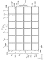
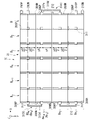
- FIG. 14 is a plan view showing an example of the tandem solar cell of the third embodiment.
- tandem solar cell 10 of this embodiment is formed by connecting a plurality of the tandem solar cells 1 of the first embodiment.
- the following description will focus on the differences from the first embodiment.
- the number of tandem solar cells 1 is not particularly limited, six tandem solar cells 1 are connected in the example shown in FIG.
- tandem solar cells 1 are distinguished from each other, they are described as tandem solar cells Sb 1 , Sb 2 , Sb 3 , Sb 4 , Sb 5 and Sb 6 , respectively.
- the tandem solar cells Sb 1 , Sb 2 , Sb 3 , Sb 4 , Sb 5 and Sb 6 may be collectively referred to as “tandem solar cells Sb 1 -Sb 6 ”.
- Each of the tandem solar cells Sb 1 -Sb 6 has a top cell module 2 and a bottom cell module 3 as in the first embodiment.
- the top cell modules 2 and the bottom cell modules 3 are connected in series.
- tandem solar cells Sb 1 , Sb 2 , and Sb 3 are arranged in this order in the negative direction of the X-axis.
- Tandem solar cells Sb 4 , Sb 5 and Sb 6 are arranged in the positive Y-axis direction of tandem solar cells Sb 1 , Sb 2 and Sb 3 , respectively.
- the first positive terminal 210P and the second negative terminal 310N of the tandem solar cell Sb1 are electrically connected to the first negative terminal 210N and the second positive terminal 310P of the tandem solar cell Sb2 via wiring, respectively. ing. Between the tandem solar cells Sb 2 and Sb 3 , between the tandem solar cells Sb 3 and Sb 4 , between the tandem solar cells Sb 4 and Sb 5 , and between the tandem solar cells Sb 5 and Sb 6 are also connected via wiring. are electrically connected in the same way.
- the first negative terminal 210N in the tandem solar cell Sb1 is the first negative terminal 20N, which is a negative terminal for taking out the overall power output of the top cell modules 2 connected in series.
- the first positive electrode terminal 210P in the tandem solar cell Sb 6 is the first positive electrode terminal 20P that is a positive electrode terminal that extracts the power output of the entire top cell modules 2 connected in series.
- the second positive electrode terminal 310P in the tandem solar cell Sb1 is the second positive electrode terminal 30P that is a positive electrode terminal that extracts the power output of the entire bottom cell modules 3 connected in series.
- the second negative terminal 310N in the tandem solar cell Sb 6 is the second negative terminal 30N, which is a negative terminal for taking out the overall power output of the bottom cell modules 3 connected in series.
- the first positive terminal 20P and the first negative terminal 20N are wired to input terminals 12P and 12N of a PCS (Power Conditioning System) 11, respectively.
- the second positive terminal 30P and the second negative terminal 30N are wired to the input terminals 13P and 13N of the PCS 11, respectively.
- the PCS 11 outputs the power output of the tandem solar cell 10 input to the input terminals 12P, 12N, 13P and 13N as DC output from the output terminals 14P and 14N.
- the tandem solar cell 10 of the present embodiment includes tandem solar cells Sb 1 -Sb 6 , which are examples of tandem modules in which a top cell module and a bottom cell module overlap in the thickness direction. Each top cell module 2 in each tandem module is electrically connected, and each bottom cell module 3 is electrically connected.
- the tandem solar cell 10 has a first positive terminal 20P, a first negative terminal 20N, a second positive terminal 30P, and a second negative terminal 30N.
- the first positive electrode terminal 20P is electrically connected to the positive electrode (first positive electrode terminal 210P) of the top cell module 2 in the tandem solar cell Sb1, which is one of the tandem modules.
- the first negative terminal 20N is electrically connected to the negative electrode (first negative terminal 210N) of the top cell module 2 in the tandem solar cell Sb6, which is one of the tandem modules.
- the second positive electrode terminal 30P is electrically connected to the positive electrode (second positive electrode terminal 310P) of the bottom cell module 3 in the tandem solar cell Sb1, which is one of the tandem modules.
- the second negative electrode terminal 30N is electrically connected to the negative electrode (second negative electrode terminal 310N) of the bottom cell module 3 in the tandem solar cell Sb6, which is one of the tandem modules.
- the tandem solar cell 10 of this embodiment is the same as the first embodiment except that the top cell module 2 and the bottom cell module 3 are divided into a plurality of tandem modules. Therefore, as in the first embodiment, it is possible to provide a tandem solar cell capable of improving insulation between the top cell module and the bottom cell module with a simple configuration in each tandem module.
- first to sixth modifications described later are modifications regarding the arrangement of the first string connect 212 and the first negative terminal 210N in the top cell module 2, 2A in the first or second embodiment.
- the first to sixth modifications differ only in the configurations of the tandem solar cells 1, 1A and the top cell modules 2, 2A.
- connection configuration of each top cell module will be explained using an example of 6 parallel 4 series.
- Seventh and eighth modifications described later include modifications of the arrangement of the cell connects of the bottom cell module.
- FIG. 15 is a plan view showing an example of a tandem solar cell of the first modified example.
- the tandem solar cell 1B of this modification has a top cell module 2B instead of the top cell module 2 of the tandem solar cell 1 of the first embodiment.
- the points different from the first embodiment will be mainly described.
- each first string connect 212 in the X-axis direction is opposite to the arrangement position of each first string connect 212 in the top cell module 2B.
- the first negative electrode terminal 210N is joined from above to the negative electrode 206N at the end of the top cell string Ts1 in the negative direction of the X axis
- the first positive electrode terminal 210P is connected to the X-axis electrode of the top cell string Ts4. It is joined from above to the positive electrode 206P at the end in the axial negative direction.
- the top cell module 2B is the same as the top cell module 2 in the first embodiment except for the above two points.
- top cell strings Ts 1 and Ts 2 are electrically connected by a first string connect 212 joined from above to the negative electrode 206N and the positive electrode 206P at the ends in the positive direction of the X axis.
- Top cell strings Ts 3 and Ts 4 are the same.
- the top cell strings Ts 2 and Ts 3 are electrically connected by a first string connect 212 joined from above to the negative electrode 206N and the positive electrode 206P at the ends in the negative direction of the X-axis.
- the second extending portion 312b of the second string connect 312 is adjacent to the first extending portion 212b of the first string connect 212 in the Y-axis direction in plan view. Adjacent means that the first extending portion 212b and the second extending portion 312b do not overlap each other in plan view. Therefore, in this modified example, the first extending portion 212b and the second extending portion 312b are arranged apart from each other in plan view. In this modified example, unlike the first embodiment, the second extending portion 312b does not surround any of the first extending portions 212b from the outside in plan view. Therefore, for example, the extension length in the X-axis direction of the second extension portion 312b can be made shorter than in the first embodiment. Furthermore, the separation distance between the first string connect 212 and the second string connect 312 in plan view can be increased. As a result, in this modified example, it is possible to further improve the insulation between the first string connect 212 and the second string connect 312 .
- the first negative terminal 210N and the first positive terminal 210P are provided on the opposite side of the second positive terminal 310P and the second negative terminal 310N in the X-axis direction.
- the output of the top cell module 2B and the power output of the bottom cell module 3 can be extracted from different directions in the X-axis direction.
- the first string connect 212 connects the top cell strings Tsj adjacent to each other in the Y-axis direction
- the second string connect 212 connects the bottom cell strings Bsj overlapping the top cell strings Tsj
- the string connect 312 can be connected at the opposite position in the X-axis direction. Thereby, the first string connect 212 and the second string connect 312 can be separated from each other.
- one of the first negative terminal 210N and the first positive terminal 210P may be provided at the same position as in the second modified example.
- FIG. 16 is a plan view showing an example of a tandem solar cell of the second modified example.
- the tandem solar cell 1C of this modification has a top cell module 2C instead of the top cell module 2 of the tandem solar cell 1 of the first embodiment.
- the points different from the first embodiment will be mainly described.
- the top cell module 2C has three first string connects 212 added in addition to the same first string connects 212 as in the first embodiment.
- the added first string connects 212 are arranged at the same positions as the respective first string connects 212 in the first modified example.
- the negative electrode 206N and the positive electrode 206P at both ends in the X-axis direction of the top cell strings Ts 1 -Ts 4 are electrically connected by the first string connect 212 .
- FIG. 17 is a plan view showing an example of a tandem solar cell of the third modified example. As shown in FIG. 17, the tandem solar cell 1D of this modification has a top cell module 2D instead of the top cell module 2C of the tandem solar cell 1C of the second modification. In the following, the points different from the second modified example will be mainly described.
- the first negative terminal 210N and the first positive terminal 210P are provided on the opposite side of the second positive terminal 310P and the second negative terminal 310N in the X-axis direction. It is the same as the second modified example except that the
- FIG. 18 is a plan view showing an example of a tandem solar cell of the fourth modification. As shown in FIG. 18, the tandem solar cell 1E of this modification has a top cell module 2E instead of the top cell module 2A of the tandem solar cell 1A of the second embodiment. In the following, the points different from the second embodiment will be mainly described.
- each first string connect 212 in the X-axis direction is opposite to the arrangement position of each first string connect 212 in the top cell module 2A.
- the first negative terminal 210N is connected from above to the first cell connect 211A at the end of the top cell string Ts1 in the negative direction of the X axis
- the first positive terminal 210P is connected to the top cell string Ts4 .
- the top cell module 2E is the same as the top cell module 2A in the second embodiment, except for the above two points. That is, this modification is an example in which the tandem solar cell 1A of the second embodiment is modified in the same manner as in the first modification.
- FIG. 19 is a plan view showing an example of a tandem solar cell of the fifth modified example.
- the tandem solar cell 1F of this modification has a top cell module 2F instead of the top cell module 2A of the tandem solar cell 1A of the second embodiment.
- the points different from the second embodiment will be mainly described.
- the top cell module 2F has three first string connects 212 added in addition to the first string connects 212 similar to those of the second embodiment.
- the added first string connects 212 are arranged in the same positions as the respective first string connects 212 in the fourth modification.
- the first cell connects 211A at both ends in the X-axis direction of the top cell strings Ts 1 -Ts 4 are electrically connected by the first string connects 212 . That is, this modification is an example in which the tandem solar cell 1A of the second embodiment is modified in the same manner as in the second modification.
- FIG. 20 is a plan view showing an example of a tandem solar cell of the sixth modification.
- the tandem solar cell 1G of this modified example has a top cell module 2G instead of the top cell module 2F of the tandem solar cell 1F of the fifth modified example.
- the points different from the fifth modified example will be mainly described.
- the first negative terminal 210N and the first positive terminal 210P are provided on the opposite side of the second positive terminal 310P and the second negative terminal 310N in the X-axis direction. It is the same as the fifth modified example except that the
- FIG. 21 is a back view showing an example of the tandem solar cell of the seventh modified example.
- the tandem solar cell 1H of this modification has a bottom cell module 3H instead of the bottom cell module 3 of the tandem solar cell 1 of the first embodiment.
- the following description will focus on the differences from the first embodiment.
- the bottom cell module 3H has two second string connects 313H and one second string connect 314H.
- Each second string connect 313H is similar to the second string connect 312 except that it is shorter in the Y-axis direction. That is, each second string connect 313H has a linear portion 313c shorter than the linear portion 312c instead of the linear portion 312c. Each second string connect 313H connects bottom cell strings Bs 1 and Bs 2 and bottom cell strings Bs 3 and Bs 4 in series at the ends in the negative direction of the X axis.
- the second string connect 314H is similar to the second string connect 312 except that it is longer in the Y-axis direction. That is, the second string connect 314H has a linear portion 314c that is longer than the linear portion 312c instead of the linear portion 312c.
- the second string connect 314H connects the bottom cell strings Bs 2 and Bs 3 in series at the end in the positive direction of the X axis.
- the Y-axis direction center lines of the connection portion 312a on the Y-axis positive direction side of the second string connect 313H, each of the second cell connects 311, and the second positive electrode terminal 310P are aligned with the bottom It extends in the X-axis direction at a distance y1 (where y1>y0/2) from the end of the cell string Bs1 in the positive Y - axis direction.
- the Y-axis negative direction side connection portion 312a of the second string connect 313H, each second cell connect 311, and the Y-axis positive direction connection portion 312a of the second string connect 314H are The center line in the Y-axis direction extends in the X-axis direction at a distance y2 from the end of the bottom cell string Bs2 in the positive Y - axis direction.
- the connecting portion 312a of the second string connect 313H on the positive Y-axis direction side, the connecting portion 312a of each second cell connect 311, and the negative Y-axis direction connecting portion 312a of the second string connect 314H
- the center line in the Y-axis direction has the same positional relationship as the bottom cell string Bs1.
- the Y-axis direction center lines of the connection portion 312a on the Y-axis negative direction side of the second string connect 313H, each of the second cell connects 311, and the second negative electrode terminal 310N are aligned with the bottom It has the same positional relationship as the cell string Bs2 .
- This modification is an example in which the connection positions of the positive electrodes 306P and the negative electrodes 306N of the bottom cells Bi are all shifted from the centers of the positive electrodes 306P and the negative electrodes 306N in the Y-axis direction.
- the distance between the first negative electrode terminal 210N and the second positive electrode terminal 310P and the distance between the first positive electrode terminal 210P and the second negative electrode terminal 310N in plan view are the same as those of the first embodiment. It can be separated from the form.
- FIG. 22 is a back view showing an example of the tandem solar cell of the eighth modification.
- the tandem solar cell 1I of this modification has a bottom cell module 3I instead of the bottom cell module 3 of the tandem solar cell 1 of the first embodiment.
- the points different from the first embodiment will be mainly described.
- the bottom cell module 3I has second string connects 313I and 314I instead of the two second string connects 312 .
- the bottom cell strings Bs 1 and Bs 2 in this modification are connected in series by the second string connect 312 as in the first embodiment.
- the second string connect 313I is similar to the second string connect 312 except that the length in the Y-axis direction is shorter. That is, the second string connect 313I has a linear portion 313d shorter than the linear portion 312c instead of the linear portion 312c.
- the second string connect 313I connects the bottom cell strings Bs 3 and Bs 4 in series at the end in the negative direction of the X axis.
- the second string connect 314I is similar to the second string connect 312 except that it is longer in the Y-axis direction. That is, the second string connect 314I has a linear portion 314d longer than the linear portion 312c instead of the linear portion 312c.
- the second string connect 314I connects the bottom cell strings Bs 2 and Bs 3 in series at the end in the positive direction of the X axis.
- the Y-axis positive direction connection portion 312a in the second string connect 314I is electrically connected to the negative electrode 306N in the center of the Y-axis direction of the negative electrode 306N in the bottom cell B1.
- connection portion 312a of the second string connect 313I on the positive Y-axis direction side, the connection portion 312a of each second cell connect 311, and the Y-axis negative direction connection portion 312a of the second string connect 314I
- the center line in the Y-axis direction extends in the X-axis direction at a distance y4 (where y4>y0/2) from the end of the bottom cell string Bs3 in the positive Y - axis direction.
- the center lines in the Y-axis direction of the connection portion 312a on the Y-axis negative direction side of the second string connect 313I, each of the second cell connects 311, and the second negative terminal 310N are aligned with the bottom It extends in the X-axis direction at the center of the cell string Bs 4 in the Y-axis direction.
- connection positions of the positive electrodes 306P and the negative electrodes 306N of the bottom cells Bi are shifted from the center of the positive electrodes 306P and the negative electrodes 306N in the Y-axis direction only in the bottom cell string Bs3. This is an example.
- bottom cells Bi being back-contact solar cells
- the bottom cell B i is not limited to back-contact solar cells.
- the bottom cell Bi may be a crystalline silicon solar cell, a monocrystalline, polycrystalline, amorphous silicon solar cell, or a CIS or CIGS compound solar cell. Examples of crystalline silicon solar cells are described below.
- FIG. 23 is a cross-sectional view showing an example of a crystalline silicon solar cell that can be used in each embodiment and each modification.
- the bottom cell string 500 has a plurality of bottom cells 510 connected in series.
- Each bottom cell 510 has an n-electrode 511, an antireflection film 512, an n-type semiconductor 513, a p-type semiconductor 514, and a p-electrode 515 stacked in this order in the Z-axis negative direction.
- the bottom cell 510 generates a voltage between the p-type semiconductor 514 and the n-type semiconductor 513 when receiving the incident light L′.
- the generated voltage becomes the voltage between the p-electrode 515 and the n-electrode 511 .
- the p-electrodes 515 and n-electrodes 511 of the bottom cells 510 adjacent to each other are electrically connected to each other by a cell interconnector 520 formed of a conductor.
- each bottom cell 510 of the bottom cell string 500 is connected in series.
- FIG. 23 schematically shows the cell interconnector 520 , so that it protrudes upward and downward in the thickness direction (Z-axis direction) of the bottom cell 510 .
- Each cell interconnector 520 is arranged at any position in the thickness direction (Z-axis direction) of the bottom cell 510 .
- the electrodes in the top cell module may be electrodes formed in a mesh shape, and may be configured to allow light to pass through the gaps of the mesh.
- a similar electrode structure can also be employed for the p-electrode 515 in the bottom cell 510 .
- the outer shape of the top cell T i and the bottom cell B i in plan view is rectangular has been described.
- the outlines of the top cell T i and the bottom cell B i are not limited to rectangles.
- a rectangular shape with rounded or rounded corners, or a polygonal shape other than a rectangular shape may be used.
- top cell module and the bottom cell module are rectangular.
- outlines of the top cell module and bottom cell module are not limited to rectangles.
- shapes other than rectangles such as substantially trapezoidal and substantially polygonal shapes can be formed.
- the first positive terminal, the first negative terminal, the second positive terminal, and the second negative terminal all form the third extension.
- the first positive terminal, the first negative terminal, the second positive terminal, and the second negative terminal may not form the third extension.
- a first positive terminal, a first negative terminal, a second positive terminal, a second negative terminal, or a combination thereof may form the third extension.
- tandem solar cells may include bypass diodes.
- tandem solar cell Sb 1 is provided with the first negative electrode terminal 20N and the second positive electrode terminal 30P
- tandem solar cell Sb 6 is provided with the first positive electrode terminal 20P and the second negative electrode terminal 30N.
- first negative terminal 20N, the first positive terminal 20P, the second positive terminal 30P, and the second negative terminal 30N are provided in any of the plurality of tandem modules according to the connection configuration of the plurality of tandem modules. good too.
- tandem module may include tandem solar cell of the second embodiment described above, the tandem solar cells of the first to eighth modifications, or other tandem solar cells. .
- each of the tandem modules has four external output terminals, the first positive terminal 20P, the first negative terminal 20N, the second positive terminal 30P, and the second negative terminal.
- An example in which the external output terminals other than the terminal 30N are electrically connected has been described. That is, in the third embodiment, independently usable tandem solar cells are configured as a plurality of tandem modules. However, the plurality of tandem modules may be configured without four external output terminals that can be used independently. That is, the plurality of tandem modules need not have external output terminals other than the first positive terminal 20P, the first negative terminal 20N, the second positive terminal 30P, and the second negative terminal 30N.
- a top cell string in which a plurality of top cells are electrically connected is arranged so as to overlap the top cell string in plan view in the thickness direction of the top cell.
- a bottom cell string electrically connected to a plurality of bottom cells; a top cell module electrically connected to the plurality of top cell strings; and a first extension extending outside the top cell module in plan view.
- a first string connect having an extension, a bottom cell module electrically connected to the plurality of bottom cell strings, and a second string having a second extension extending outside the bottom cell module in plan view.
- first extension portion and the second extension portion are arranged apart from each other in the plan view, so that insulation between the top cell module and the bottom cell module can be achieved with a simple configuration. It is possible to provide a tandem solar cell that can improve the
Landscapes
- Photovoltaic Devices (AREA)
- Life Sciences & Earth Sciences (AREA)
- Engineering & Computer Science (AREA)
- Sustainable Development (AREA)
- Sustainable Energy (AREA)
Abstract
Description
タンデム太陽電池には、トップセルとボトムセルを直列接続した2端子構造や、トップセルとボトムセルを電気的に分離した4端子構造などがある。2端子構造の場合、トップセルとボトムセルに流れる光電流が必ず一致する電流整合の制約条件が存在するため、太陽光の入射角度や天候などが最適照射条件から外れた時に、発電量が大きく減少する短所がある。これに対して、4端子構造の場合、電流整合の制約が無いため、発電量は、とくに太陽光の最適照射条件から外れた時に2端子構造より大きくなる長所がある(最適照射条件では同等)。
4端子構造タンデム太陽電池では、トップセルと、ボトムセルとは、互いに絶縁する必要がある。トップセルを複数並べたトップセルモジュールと、ボトムセルを複数並べたボトムセルモジュールを積層した4端子構造タンデム太陽電池モジュールにおいても、トップセルモジュールとボトムセルモジュールとは、互いに絶縁されている。
トップセル(ボトムセル)を複数並べてトップセル(ボトムセル)モジュールを形成する場合、トップセル(ボトムセル)を一方向に短冊状に並べて電気的に接続したトップセル(ボトムセル)ストリングを形成し、各トップセル(各ボトムセル)ストリングの接続方向の両端部同士をストリングコネクトで接続することが多い。トップセルモジュールおよびボトムセルモジュールの各ストリングコネクトは、タンデム太陽電池の厚さ方向に近接するので、互いに確実に絶縁する必要がある。
ストリングコネクト同士を絶縁する絶縁構造を設けることによって、タンデム太陽電池の構造が複雑になったり、タンデム太陽電池が大型化したりする可能性がある。
第1の実施形態のタンデム太陽電池を説明する。
図1は、第1の実施形態のタンデム太陽電池の例を示す平面図である。図2は、図1におけるF2-F2線に沿う断面図である。図3は、図1におけるF3部の斜視図である。図4は、図1におけるF4部の斜視図である。
図2に示すように、タンデム太陽電池1は、トップセルモジュール2と、ボトムセルモジュール3と、を有する。トップセルモジュール2とボトムセルモジュール3とは、光透過性を有する絶縁層4を介在して互いの厚さ方向にメカニカルに接合されており、電気的にはトップセルモジュール2とボトムセルモジュール3とは互いに分離されている。例えば、絶縁層4は、透明な基材の表面に透明な樹脂接着剤が塗布されて形成される。
以下では、トップセルT1、…、Tnのうちの任意の1つを表す場合、iが1からnのいずれかを表すとして、「トップセルTi」と記載する場合がある。トップセルストリングTs1、…、Tsmのうちの任意の1つを表す場合、jが1からmのいずれかを表すとして、「トップセルストリングTsj」と記載する場合がある。
トップセルT1、…、Tnの全体は、「トップセルT1-Tn」と、トップセルストリングTs1、…、Tsmの全体は、「トップセルストリングTs1-Tsm」と、記載する場合がある。
以下では、簡単のため、トップセルストリングTsjにおけるトップセルT1-Tnのそれぞれの定格出力は、互いに同一である例で説明する。
トップセルストリングTs1-Tsmにおいて、添字jが異なる場合、それぞれに含まれる同一の添字iのトップセルTi同士の各定格出力は、同一でもよいし、同一でなくてもよい。以下では、簡単のため、添字jが異なるトップセルストリングTsj同士における各トップセルTiの定格出力は、互いに同一である例で説明する。
すなわち、以下の説明では、各トップセルTiの定格出力と、各トップセルストリングTsjの定格出力は、それぞれ同一である。
X軸方向の正方向(X軸正方向)は、トップセルTiの添字iが降順になる並びの方向である。Y軸方向の正方向(Y軸正方向)は、トップセルストリングTsjの添字jが降順になる並びの方向である。Z軸方向の正方向(Z軸正方向)は、トップセルモジュール2の入射面の法線方向において、ボトムセルモジュール3からトップセルモジュール2に向かう方向である。X軸負方向、Y軸負方向、およびZ軸負方向は、それぞれ、X軸正方向、Y軸正方向、およびZ軸正方向の反対方向である。
Z軸方向は、Z軸正方向を上方、Z軸負方向を下方とする上下方向である。以下では、特に断らない限り、上、下は、Z軸方向における上、下を意味する。
トップセルT2は、基板201と、直列アレイセルAと、を有する。
基板201は、トップセルT2の下層部を形成する板部材である。基板201の材料は、光透過性を有していれば特に限定されない。基板201の透過率は高いほどより好ましい。例えば、基板201の材料は、ガラスであることがより好ましい。例えば、基板201の材料は、アクリル、ポリイミド、ポリカーボネート、ポリエチレンテレフタレート(PET)、ポリプロピレン(PP)、フッ素系樹脂(ポリテトラフルオロエチレン(PTFE)、パーフルオロエチレンプロペンコポリマー(FEP)、エチレンテトラフルオロエチレンコポリマー(ETFE)、ポリクロロトリフルオロエチレン(PCTFE)、パーフルオロアルコキシアルカン(PFA)など)、ポリアリレート、ポリサルフォン、ポリエーテルサルフォンやポリエーテルイミドなどの透明樹脂や、ソーダライムガラス、白板ガラス、化学強化ガラスや石英など無機材料などを用いることができる。基板201は、上記に挙げた材料を積層してもよい。
基板201は、板厚方向がZ軸方向に一致する姿勢で、絶縁層4におけるZ軸正方向の表面にメカニカルに接合されている。
基板201は、トップセルT2の平面視の外形を規定している。平面視におけるトップセルT2の外側とは、平面視において、基板201の外周部よりも外の領域を指す。
図3にトップセルストリングTs1におけるトップセルT1の例で示すように、基板201の平面視形状は、X軸方向に延びる2辺と、Y軸方向に延びる2辺と、を有する矩形である。
直列アレイセルAは、負電極部A0、k個(kは、2以上の整数)の単位セルA1、…、Ak、および正電極部Ak+1を有する。単位セルA1、…、Akの個数kは2以上であれば特に限定されない。例えば、kは25であってもよい。
単位セルA1、…、Akは、トップセルモジュール2の上方から入射する入射光Lの一部を吸収してそれぞれ発電を行う。図2には、入射光Lがトップセルモジュール2に垂直入射するように描かれているが、入射光Lの入射角は垂直には限定されない。
単位セルA1、…、Akは、負電極部A0と正電極部Ak+1との間で直列に接続されている。
負電極部A0、単位セルA1、…、Ak、および正電極部Ak+1の平面視形状は、いずれも、基板201におけるX軸方向の全幅において、X軸方向に延びる帯状である。
負電極部A0、単位セルA1、…、Ak、および正電極部Ak+1は、平面視において、基板201のY軸正方向の端部からY軸負方向の端部に向かって、この順に配置されている。
裏面透明電極層202は、光透過性を有する導電膜で形成されている。例えば、裏面透明電極層202は、1層以上の酸化物透明導電膜を含むことが好ましい。
酸化物透明導電膜の種類は特に限定されない。例えば、酸化物透明導電膜としては、酸化インジウムスズ(Indium Tin Oxide;ITO)、アルミニウムドープ酸化亜鉛(Al-doped Zinc Oxide;AZO)、ボロンドープ酸化亜鉛(Boron-doped Zinc Oxide;BZO)、ガリウムドープ酸化亜鉛(Gallium-doped Zinc Oxide;GZO)、ドープされた酸化スズ、チタンドープ酸化インジウム(Titanium-doped Indium Oxide;ITiO)、酸化インジウム酸化亜鉛(Indium Zinc Oxide;IZO)や酸化インジウムガリウム亜鉛(Indium Gallium Zinc Oxide;IGZO)、水素ドープ酸化インジウム(Hydrogen-doped Indium Oxide;IOH)などの半導体導電膜が挙げられる。
例えば、酸化物透明導電膜は、複数の膜を持つ積層膜であってもよい。
酸化スズなどの膜へのドーパントは特に限定されない。例えば、ドーパントとしては、In、Si、Ge、Ti、Cu、Sb、Nb、Ta、W、Mo、F、及びClからなる群から選ばれる1種以上の元素が挙げられる。
裏面透明電極層202は、In、Si、Ge、Ti、Cu、Sb、Nb、Ta、W、Mo、F、及びClからなる群から選ばれる1種以上の元素がドープされた酸化スズ膜が含まれることが好ましい。ドープされた酸化スズ膜において、In、Si、Ge、Ti、Cu、Sb、Nb、Ta、W、Mo、F、及びClからなる群から選ばれる1種以上の元素は、酸化スズ膜に含まれるスズに対して10原子%以下含まれることが好ましい。
ドット状、ライン状もしくはメッシュ状の電極は、酸化物透明導電膜の電気抵抗が高く、それ単独では電圧降下による効率低下が生じる場合に適用するのが有効である。
ドット状、ライン状もしくはメッシュ状の電極に用いられる金属は、酸化物透明導電膜に対して開口率が95%以上であることが好ましい。
ドット状、ライン状もしくはメッシュ状の電極に用いられる金属は、特に限定されないが、例えば、Mo、Au、Cu、Ag、Al、Ta、Wなどが挙げられる。
電極としてライン状やメッシュ状の金属膜を用いる場合、開口部によって必要な光透過性が確保され、さらに電気抵抗が酸化物透明導電膜よりも低くなれば、金属膜の膜厚は特に限定されない。
単位セルAkの下層部を形成する裏面透明電極層202は、平面視において、単位セルAkの上層部よりもY軸負方向に突出している。単位セルAkの上層部よりもY軸負方向に突出した裏面透明電極層202上には、正電極部Ak+1が形成されている。
負電極206Nは、金属膜などの導電材料で形成されている。金属膜の材料は特に限定されない。
例えば、負電極206Nは、後述する表面透明電極層205と同様な導電膜で形成されてもよい。例えば、負電極206Nに用いる金属膜の材料として、Mo、Au、Cu、Ag、Al、Ta、Wなどが挙げられる。また、金属膜として、導電性を持つ金属ペーストを用いることも好ましい。
単位セルA1、…、Akは、入射光Lを光電変換することで発電するとともに、入射光Lの一部を下方に透過させることができれば、どのような構成を有していてもよい。例えば、単位セルA1、…、Akは、上述の層構成に加えて、保護フィルム、封止材などが適宜追加されてよい。例えば、発電層であるp-Cu2O層203およびn-化合物層204に入射する入射光Lの光量を増大する目的で、n-化合物層204の上面に反射防止膜が形成されてもよい。
単位セルA1、…、Akの種類は、亜酸化銅太陽電池には限定されない。例えば、単位セルA1、…、Akの種類は、色素増感太陽電池、有機薄膜系太陽電池、ペロブスカイト太陽電池などであってもよい。
n-化合物層204は、入射光Lによってp-Cu2O層203で発生した電子を表面透明電極層205まで輸送するn型半導体であり、p-Cu2O層203の上面に積層されている。n-化合物層204は、p-Cu2O層203とヘテロpn接合を形成している。
n-化合物層204は、特に限定されるものではないが、Gaを含む酸化物半導体層であって、Gaを主成分とする化合物を含むことが好ましい。例えば、n-化合物層204はGaを主成分とする酸化物に他の酸化物が混合していてもよいし、Gaを主成分とする酸化物に他の元素がドープしていてもよいし、他の元素がドープしたGaを主成分とする酸化物と他の酸化物が混合していてもよい。
n-化合物層204は、単層又は多層である。n-化合物層204に含まれる金属元素のうち、Gaは50原子%以上であることが好ましい。
n-化合物層204に含まれる金属元素は、p-Cu2O層203側から表面透明電極層205側に傾斜していてもよい。
n-化合物層204は、Sn、Sb、Ag、Li、Na、K、Cs、Rb、Al、In、Zn、Mg、Si、Ge、N、B、Ti、Hf、Zr、及びCaからなる群より選ばれる1種以上の元素の酸化物とGaの酸化物とを90wt%以上含むことが好ましい。
単位セルA1、…、Akのうち、Y軸方向に隣り合う単位セル同士は、導電路208を介在して直列接続されている。
導電路208としては、裏面透明電極層202と表面透明電極層205とを電気的に接続できる適宜の導電体が用いられる。図2では、各導電路208は模式的に線状に描かれているが、線状の配線には限定されない。例えば、各導電路208は、p-Cu2O層上にn-化合物層204を形成したのちに溝加工を施して、当該箇所において裏面透明電極層202を露出させた後に、表面透明電極層205を製膜することで、溝部を介して裏面透明電極層202と表面透明電極層205とを電気的に接続した構成とされてもよい。
単位セルA1における表面透明電極層205は、導電路208によって負電極部A0の負電極206Nと導通している。
特に、単位セルA1、…、Akの各表面透明電極層205の上面は、いずれもZ軸方向に延びる法線を有する平面Isと略同一平面上に位置する。
図2では、負電極206Nおよび正電極206Pの各上面が、平面Isよりも低く描かれているが、各上面の高さはこれには限定されない。例えば、負電極206Nの上面および正電極206Pの上面の一方または両方は、平面Isと同一の高さ以上の高さに位置していてもよい。
図1に示すように、トップセルTiは、負電極206NがY軸正方向、正電極206PがY軸負方向に位置した状態で、X軸方向およびY軸方向に矩形格子状に配置されている。なお、図1では、簡単のため、直列アレイセルAの詳細構造の図示は省略している。
各トップセルストリングTsjにおいて、X軸方向に互いに隣り合うトップセルTiは、それぞれ第1セルコネクト211によって電気的に接続されている。第1セルコネクト211は、負電極206N同士、または正電極206P同士を電気的に接続する導体である。
第1セルコネクト211の構成は、負電極206N同士と、正電極206P同士と、それぞれ電気的に接続できれば、特に限定されない。図3に示す例では、第1セルコネクト211は、負電極206Nおよび正電極206Pの長さよりも短く、短手幅(Y軸方向の幅)以下の幅を有するリボン状の導体である。
なお、図3では、簡単のため、直列アレイセルAの詳細構造の図示は省略している。
同様に、第1セルコネクト211は、X軸方向において互いに隣り合う正電極206Pの上側に跨がって配置されており、例えば、導電ペーストや半田材などによって各正電極206Pに接合されている。正電極206P同士を接合する第1セルコネクト211として、負電極206N同士を接合する第1セルコネクト211と同様、1個のストリングを構成する複数セル全体を跨って各正電極206Pに接合されている、1本の長いセルコネクトが用いられてもよい。
第1セルコネクト211によって電気的に接続された各トップセルストリングTsjの各負電極206Nと各正電極206Pとは、入射光Lが入射する表面側に設けられている。第1セルコネクト211によって電気的に接続された各トップセルストリングTsjの各負電極206Nと各正電極206Pとは、後述する各ボトムセルストリングBsjと対向する面の反対側の面側に設けられた第1電極部の例である。
トップセルストリングTs2、Ts3におけるX軸正方向の端部(トップセルT1)の正電極206Pと負電極206Nとは、第1ストリングコネクト212によって、互いに電気的に接続されている。
トップセルストリングTs3、Ts4におけるX軸負方向の端部(トップセルTn)の正電極206Pと負電極206Nとは、第1ストリングコネクト212によって、互いに電気的に接続されている。
このため、第1ストリングコネクト212は、トップセルストリングTsjのうち、平面視において互いに異なるトップセルストリングTsj同士を、それぞれの第1電極部において、互いに電気的に接続している。
図1に示す例では、各第1ストリングコネクト212はいずれも同じ形状を有する。各第1ストリングコネクト212は平面視においてY軸方向に開口するU字状に形成され、負電極206Nおよび正電極206Pの短手幅以下の幅を有するリボン状の導体である。
図4に示すように、第1ストリングコネクト212は、正電極206Pと負電極206Nとに、それぞれ上側から接続する接続部212aと、平面視においてトップセルモジュール2の外側に延びる第1延出部212bと、を有する。
各接続部212aは、Y軸方向において互いに隣り合う正電極206Pと負電極206Nとの上側に配置されている。各接続部212aは、例えば、導電ペーストや半田材などによって正電極206Pと負電極206Nとに接合されている。
第1延出部212bは、各接続部212aからX軸正方向に延在し、平面視U字状に屈曲または湾曲する経路に沿って、基板201の外形で規定される各トップセルT1の外形の外側に延びている。
第1延出部212bのX軸方向における延出長は、例えば、d1である。
第1ストリングコネクト212は、複数の導体が互いに接合されて構成されてもよい。例えば、第1ストリングコネクト212は、第1セルコネクト211と同様な第1導体と、第1導体同士を接合する第2導体と、を有していてもよい。
各第1導体は、正電極206Pと負電極206Nとの上側に接合される。
第2導体としては、第1導体をY軸方向に接合するリボン状の導体、または第1延出部212bと同様な平面視U字形を有しU字形の先端部が各第1導体上に接合された導体、などを用いることができる。
この場合、第1ストリングコネクト212は、各第1導体と第2導体とが接合された平面視U字形を有する。正電極206Pおよび負電極206N上の各第1導体は、接続部212aと同様の接続部を形成する。各トップセルT1の外形の外側に位置する、各第1導体と第2導体とは、第1延出部212bと同様の第1延出部を形成する。
第1負極端子210Nの構成は、負電極206Nと電気的に接続でき、トップセルモジュール2の正極の出力を外部に取り出す外部配線を接続できれば、特に限定されない。
図3に示す例では、第1負極端子210Nは、負電極206Nに上側から接続する接続部210aと、平面視においてトップセルモジュール2の外側に延びる第3延出部210bと、を有する。
接続部210aは、Y軸方向において負電極206Nの短手幅以下の幅を有し、X軸方向において負電極206Nの長手幅未満の幅を有する。
図3では、第3延出部210bの延出方向の先端部には、外部配線を接続する目的で、接続部210aよりも広い幅を有する端子電極210cが描かれているが、外部配線との接続が確実に行える場合は、端子電極210cと接続部210aとのY軸方向の幅を同じにしてもよい。
例えば、第1負極端子210Nは、第1セルコネクト211と同じ材質のリボン状の金属線のような導体で形成されてもよい。
第1正極端子210Pの構成は、正電極206Pと電気的に接続でき、トップセルモジュール2の負極の出力を外部に取り出す外部配線を接続できれば、特に限定されない。
第1正極端子210Pは、第1負極端子210Nと同様、正電極206Pに上側から接続する接続部210aと、平面視においてトップセルモジュール2の外側に延びる第3延出部210bと、を有する。
第1正極端子210Pにおける接続部210aは、正電極206Pの短手幅以下の幅を有する。
図1では、第1正極端子210Pにおける第3延出部210bの延出方向の先端部には、第1負極端子210Nと同様の端子電極210cが描かれているが、外部配線との接続が確実に行える場合は、端子電極210cと接続部210aとのY軸方向の幅を同じにしてもよい。
例えば、第1正極端子210Pは、第1負極端子210Nと同様、第1セルコネクト211と同じ材質のリボン状の金属線のような導体で形成されてもよい。
図5は、第1の実施形態のタンデム太陽電池におけるトップセルモジュールの等価回路図である。
図4と図5に示すように、各トップセルストリングTsjにおけるトップセルT1-Tnは、第1セルコネクト211によって並列接続されている。
トップセルストリングTs1-Tsmは、第1ストリングコネクト212によって直列接続されている。
トップセルモジュール2は、並列接続されたn個のトップセルTiがm組直列接続された回路構成(n並列m直列)を有する。
第1負極端子210Nは、トップセルモジュール2の正極のうち、トップセルT1の負電極206Nに接続されている。
第1正極端子210Pは、トップセルモジュール2の負極のうち、トップセルT1の正電極206Pに接続されている。
トップセルモジュール2に入射光Lが入射することによって、トップセルモジュール2の各トップセルストリングTsjが発電すると、第1負極端子210Nと第1正極端子210Pとの間に電圧が生じる。第1負極端子210Nと第1正極端子210Pとに外部負荷を接続すると、第1負極端子210Nと第1正極端子210Pとから、発電出力を外部に取り出すことができる。
図6は、第1の実施形態のタンデム太陽電池の例を示す裏面図である。図7は、図1におけるF7-F7線に沿う断面図である。
ここで、ボトムセルモジュール3における個数n、mは、トップセルモジュール2における個数n、mとは相違していてもよいが、以下では、トップセルモジュール2における個数n、mに等しい例で説明する。
以下では、ボトムセルB1、…、Bnのうちの任意の1つを表す場合、iが1からnのいずれかを表すとして、「ボトムセルBi」と記載する場合がある。ボトムセルストリングBs1、…、Bsmのうちの任意の1つを表す場合、jが1からmのいずれかを表すとして、「ボトムセルストリングBsj」と記載する場合がある。
ボトムセルB1、…、Bnの全体は「ボトムセルB1-Bn」と、ボトムセルストリングBs1、…、Bsmの全体は、「ボトムセルストリングBs1-Bsm」と、記載する場合がある。
ボトムセルストリングBs1-Bsmにおいて、jが異なる場合、それぞれに含まれる同一の添字iのボトムセルBi同士の各定格出力は、同一でもよいし、同一でなくてもよい。以下では、簡単のため、添字jが異なるボトムセルストリングBsj同士における各ボトムセルBiの定格出力は、互いに同一である例で説明する。
すなわち、以下の説明では、各ボトムセルBiの定格出力と、各ボトムセルストリングBsjの定格出力は、それぞれ同一である。
ボトムセルBiの外形状および外形の大きさは、トップセルTiとは異なっていてもよい。ボトムセルBiとトップセルTiとは、X軸方向およびY軸方向の少なくとも一方にずれていてもよい。
ボトムセルB2は、入射光Lのうち、トップセルT2および絶縁層4を透過した入射光L’を受光することによって発電する太陽電池セルである。ボトムセルB2の種類は、トップセルT2で吸収されにくい波長光で発電できれば特に限定されない。
例えば、長波長光の方が媒体の深部まで到達しやすいので、トップセルT2は短波長成分によって発電し、ボトムセルB2は長波長成分によって発電できることがより好ましい。例えば、亜酸化銅太陽電池は、短波長光を吸収し長波長光を透過しやすいので、トップセルT2として好適である。トップセルT2が亜酸化銅太陽電池の場合には、ボトムセルB2としては、亜酸化銅太陽電池を透過しやすい約600nmから長波長側に分光感度を有する太陽電池が用いられることがより好ましい。
図8Aは、バックコンタクト型太陽電池セルの例を示す裏面図である。図8Bは、図8AにおけるF8B-F8B線に沿う断面図である。
図8Aに示すセル本体301の配置は、ボトムセルストリングBs1のボトムセルB2に用いる場合の例である。図8AにおけるF8B-F8B線は、図1におけるF7-F7線に対応している。
図8Bに示すように、セル本体301は、Z軸負方向において、反射防止膜302、n型半導体303、および拡散層304がこの順に積層されている。図8Bに示す構成は一例である。例えば、セル本体301には、保護フィルム、封止材などが適宜追加されてもよい。
n型半導体303は、入射光L’を受光してキャリアを発生させる。例えば、n型半導体303は、n型の結晶Si基板である。
拡散層304には、p+拡散層304Pとn+拡散層304NとがY軸方向において交互に配置されている。各p+拡散層304PのX軸正方向の端部は、Y軸方向に延びるp+拡散層304Pに接続している。各n+拡散層304NのX軸負方向の端部は、Y軸方向に延びるn+拡散層304Nに接続している。これにより、拡散層304においては、平面視櫛歯状のp+拡散層304Pおよびn+拡散層304Nが嵌合して平面視矩形状の層状部が形成されている。
n型半導体303で発生するキャリアは、p+拡散層304Pには正孔が、n+拡散層304Nには電子がそれぞれ引きつけられるので、p+拡散層304Pとn+拡散層304Nとの間に電圧が発生する。
図8Aに示すように、Z軸正方向から見た正電極306Pは、p+拡散層304Pと同様の櫛歯状の導電パターンを形成している。正電極306Pは、セル本体301で発生した正電圧を取り出す正電極として用いられる。
正電極306PにおいてX軸正方向の端部は、Y軸方向に長い帯状の導電部である。正電極306PにおけるX軸正方向の端部は、ボトムセルB1との電気的な接続に使用される。
Z軸正方向から見た負電極306Nは、n+拡散層304Nと同様の櫛歯状の導電パターンを形成している。負電極306Nの櫛歯部は、正電極306Pの櫛歯部の凹所に入り込んでいる。
負電極306Nは、セル本体301で発生した負電圧を取り出す負電極として用いられる。
負電極306NにおいてX軸負方向の端部は、Y軸方向に長い帯状の導電部である。負電極306NにおけるX軸負方向の端部は、ボトムセルB3との電気的な接続に使用される。
負電極306Nと正電極306Pとの間には、Z軸正方向から見て隙間があいており、直接的には接触していない。
例えば、模式的に表された図6、7などでは、ボトムセルBiの第2セル電極を代表して、X軸方向の端部においてY軸方向に長い正電極306Pと、X軸方向の端部においてY軸方向に長い負電極306Nと、を記載している。
以下では、特に断らない限り、正電極306Pと負電極306Nとは、それぞれ、X軸方向の端部においてY軸方向に延びる正電極306Pの部位と負電極306Nの部位と、を意味する。
図3にボトムセルストリングBs1におけるボトムセルB1の例で示すように、セル本体301の平面視形状は、X軸方向に延びる2辺と、Y軸方向に延びる2辺と、を有する矩形である。
図6に示すように、ボトムセルストリングBs1、Bs3では、各ボトムセルBiは、正電極306PがX軸正方向、負電極306NがX軸負方向に位置した状態で、X軸方向に並んで配置されている。
ボトムセルストリングBs2、Bs4では、各ボトムセルBiは、正電極306PがX軸負方向、負電極306NがX軸正方向に位置した状態で、X軸方向に並んで配置されている。
各ボトムセルストリングBsjにおいて、X軸方向に互いに隣り合うボトムセルBiは、それぞれ第2セルコネクト311によって電気的に接続されている。
第2セルコネクト311は、X軸方向に互いに隣り合うボトムセルBi同士において、互いに隣り合う負電極306Nと正電極306Pとを電気的に接続する導体である。
第2セルコネクト311の構成は、負電極306Nと正電極306Pとを電気的に接続できれば、特に限定されない。図6に示す例では、第2セルコネクト311は、正電極306Pおよび負電極306Nを下方から覆い、X軸方向に延びるリボン状の導体である。第2セルコネクト311のY軸方向の幅は、特に限定されない。図6に示す例では、正電極306Pおよび負電極306Nの長さの約5分の1程度であるが、この長さも特に限定されない。
第2セルコネクト311のY軸方向の位置は特に限定されないが、図6に示す例では、Y軸方向における正電極306Pおよび負電極306Nの中央部である。例えば、第2セルコネクト311のY軸方向における中心線は、ボトムセルBiの外形のY軸方向の幅y0を二等分する位置にある。
第2セルコネクト311によって電気的に接続された各ボトムセルストリングBsjの各正電極306Pと各負電極306Nとは、入射光Lの一部である入射光L’が入射する裏面側に設けられている。各ボトムセルストリングBsjの各正電極306Pと各負電極306Nとは、トップセルストリングTsjと対向する面と反対側の面側に設けられた第2電極部の例である。
ボトムセルストリングBs2におけるX軸正方向の端部(ボトムセルB1)の負電極306Nは、第2ストリングコネクト312によって、ボトムセルストリングBs3におけるX軸正方向の端部の正電極306Pと電気的に接続されている。
ボトムセルストリングBs3におけるX軸負方向の端部の負電極306Nは、第2ストリングコネクト312によって、ボトムセルストリングBs4におけるX軸負方向の端部の正電極306Pと電気的に接続されている。
図6に示す例では、第2ストリングコネクト312はいずれも同じ形状を有する。各第2ストリングコネクト312は、平面視においてX軸方向に開口するU字状に形成されたリボン状の導体である。
図4に示すように、第2ストリングコネクト312は、負電極306Nと正電極306Pとに、それぞれ下側から接続する接続部312aと、平面視においてボトムセルモジュール3の外側に延びる第2延出部312bと、を有する。
Y軸方向における各接続部312aの配置位置は特に限定されない。図4に示す例では、各接続部312aは、負電極306Nおよび正電極306PにおけるY軸方向の中央部にそれぞれ配置されている。
各接続部312aにおけるY軸方向の幅は、負電極306Nおよび正電極306PのY軸方向の長さよりも短い。図6に示す例では、各接続部312aにおけるY軸方向の幅は、第2セルコネクト311の幅と同様、正電極306Pおよび負電極306Nの長さの約5分の1程度である。
各接続部312aのY軸方向における配置位置は、特に限定されない。図6に示す例では、各接続部312aのY軸方向における中心線は、第2セルコネクト311と同様、ボトムセルBiの外形のY軸方向の幅y0を二等分する位置にある。
第2延出部312bの幅は、特に限定されない。図4に示す例では、接続部312aと同幅でX軸正方向に延びた後、縮幅し、略同幅で屈曲または湾曲する経路を形成している。
図1、6に示すように、平面視では、各第2延出部312bは、第1ストリングコネクト212の第1延出部212bをトップセルモジュール2およびボトムセルモジュール3の外側から挟んでいる。これにより、平面視において、各第2延出部312bと各第1延出部212bとは、重なっておらず、互いに離れている。また、第2延出部312bの長さは第1延出部212bの長さよりも短いほうが好ましい。平面視で各第2延出部312bは、第1ストリングコネクト212の第1延出部212bをトップセルモジュール2およびボトムセルモジュール3の外側から囲んでいてもよい。
例えば、図4に示す例では、第2延出部312bの延出方向の最も先端部には、各ボトムセルB1の外方においてY軸方向に延びる線状部312cが形成されている。線状部312cと各ボトムセルB1との間には、X軸方向の幅が、第1延出部212bの延出長d1よりも大きいd2の隙間が形成されている。
第2ストリングコネクト312は、複数の導体が互いに接合されて構成されてもよい。例えば、第2ストリングコネクト312は、第2セルコネクト311と同様な第1導体と、第1導体同士を接合する第2導体と、を有していてもよい。
各第1導体は、正電極306Pと負電極306Nとの下側に接合される。
第2導体としては、第1導体をY軸方向に接合するリボン状の導体、または線状部312cと同様な平面視U字形を有しU字形の先端部が各第1導体上に接合された導体、などを用いることができる。
この場合、第2ストリングコネクト312は、各第1導体と第2導体とが接合された平面視U字形を有する。正電極306Pおよび負電極306N上の各第1導体は、接続部312aと同様の接続部を形成する。各ボトムセルB1の外形の外側に位置する、各第1導体と第2導体とは、第2延出部312bと同様の第2延出部を形成する。
具体的には、このような第2ストリングコネクト312の構成は以下のようにして形成できる。例えば、第1導体として、第2セルコネクト311を正電極306Pおよび負電極306N上からボトムセルB1の外側に向かって延びるように、正電極306Pおよび負電極306Nを取り付ける。この後、リボン状の導体で形成された線状部312cに相当する第2導体を、各第2セルコネクト311に結合する。
なお、第2導体の平面視形状は、第2ストリングコネクト312のような平面視U字状には限定されない。第2導体の平面視形状は、各ボトムセルB1の外側において、第2セルコネクト311からなる第1導体同士を繋げられれば形状は問わない。
第2正極端子310P構成は、正電極306Pと電気的に接続でき、ボトムセルモジュール3の正極の出力を外部に取り出す外部配線を接続できれば、特に限定されない。
図3に示す例では、第2正極端子310Pは、正電極306Pに下側から接続する接続部310aと、平面視においてボトムセルモジュール3の外側に延びる第3延出部310bと、を有する。
接続部310aは、X軸方向において正電極306Pの短手幅以下の幅を有し、Y軸方向において正電極306Pの長手幅以下の幅を有する。例えば、接続部310aのY軸方向の幅は、第2セルコネクト311のY軸方向の幅と同程度でもよい。
第3延出部310bの延出方向の先端部には、外部配線を接続する目的で、端子電極310cが形成されている。第3延出部310bのX軸方向の延出長およびY軸方向の幅は、特に限定されない。図3に示す例では、延出長は、第3延出部210bの延出長に等しく、Y軸方向の幅は、接続部310aの幅に等しい。
例えば、第2正極端子310Pは、第1負極端子210Nと同様の導体で形成される。
Y軸方向における第2正極端子310Pの配置位置は、平面視において、第1負極端子210N、第1ストリングコネクト212、および第2ストリングコネクト312と重ならない位置であれば、特に限定されない。図6に示す例では、第2正極端子310Pは、Y軸方向において、第2正極端子310Pが設けられたボトムセルB1における第2セルコネクト311と同様の位置に設けられている。
第2負極端子310Nの構成は、負電極306Nと電気的に接続でき、ボトムセルモジュール3の負極の出力を外部に取り出す外部配線を接続できれば、特に限定されない。
第2負極端子310Nは、第2正極端子310Pと同様、負電極306Nに下側から接続する接続部310aと、平面視においてボトムセルモジュール3の外側に延びる第3延出部310bと、を有する。
第2負極端子310Nの形状は、第2正極端子310Pと異なっていてもよいいが、図6に示す例では、第2正極端子310Pと同様である。
第2負極端子310Nにおける第3延出部310bの延出方向の先端部には、第2正極端子310Pと同様の端子電極310cが形成されている。
例えば、第2負極端子310Nは、第2正極端子310Pと同じ材質のリボン状の金属線のような導体で形成されるが、導通がとれれば材質や形状は特に限定されない。
Y軸方向における第2負極端子310Nの配置位置は、平面視において、第1正極端子210P、第1ストリングコネクト212、および第2ストリングコネクト312と重ならない位置であれば、特に限定されない。図6に示す例では、第2負極端子310Nは、Y軸方向において、第2負極端子310Nが設けられたボトムセルB1における第2セルコネクト311と同様の位置に設けられている。
図9は、第1の実施形態のタンデム太陽電池におけるボトムセルモジュールの等価回路図である。
図9に示すように、各ボトムセルストリングBsjにおけるボトムセルB1-Bnは、第2セルコネクト311によって直列接続されている。
ボトムセルストリングBs1-Bsmは、第2ストリングコネクト312によって直列接続されている。
ボトムセルモジュール3は、n×m個のボトムセルBiが直列で接続された回路構成を有する。
第2正極端子310Pは、ボトムセルモジュール3の正極である正電極306Pに接続されている。
第2負極端子310Nは、ボトムセルモジュール3の負極である負電極306Nに接続されている。
ボトムセルモジュール3に入射光L’が入射することによって、ボトムセルモジュール3の各ボトムセルストリングBsjが発電すると、第2正極端子310Pと第2負極端子310Nとの間に電圧が生じる。第2正極端子310Pと第2負極端子310Nとに外部負荷を接続すると、第2正極端子310Pと第2負極端子310Nとから、発電出力を外部に取り出すことができる。
特に、ボトムセルモジュール3における各ボトムセルBiとしては、バックコンタクト型太陽電池セルを使用しているので、セルコンタクトおよび電極による入射光L’の反射および吸収による光量損失が抑制される。これにより、ボトムセルモジュール3による発電量を増大させることができる。
本実施形態のタンデム太陽電池1は、トップセルモジュール2の発電出力とボトムセルモジュール3の発電出力とを、それぞれ独立の回路を通して取り出すことができるので、各トップセルTiの接続形態と各ボトムセルBiの接続形態とを、トップセルTiとボトムセルBiとの電流比率に整合するように設定する必要がない。
このため、各トップセルTiの接続形態と、各ボトムセルBiの接続形態と、を自由に設定することができる。
タンデム太陽電池1としては、トップセルTiで効率10%、ボトムセルBiで効率20%を出して、トータル効率30%の発電を得る。トップセルモジュール2の効率と発電量とは、それぞれボトムセルモジュール3の効率と発電量との半分である。定格出力電圧が約40倍高いということは、定格出力電流がボトムセルモジュール3と比べて約80分の1と低いため、電力を取り出す外部回路はトップセル用とボトムセル用に電流と電圧の仕様が大きく異なることを意味する。このため、トップセルモジュール2の定格出力電圧は、ボトムセルモジュール3の定格電圧・定格電流に近づけることがより好ましい。
例えば、トップセルモジュール2において、並列接続のトップセルTiを増やせば、トップセルモジュール2の定格出力電圧を低減できる。
図10は、比較例のタンデム太陽電池の例を示す平面図である。
図10に示すように、比較例のタンデム太陽電池100は、タンデム太陽電池1のトップセルモジュール2に代えて、トップセルモジュール102を有する。以下、本実施形態のタンデム太陽電池1と異なる点を中心に説明する。ただし、n=6、m=4である。
第1線状部112aは、各トップセルTnの正電極206Pに接続し、平面視において各トップセルT6からX軸負方向に延出する導体である。
最もY軸負方向に位置する第1線状部112aと、Y軸正方向における第2線状部112bの端部と、の接続部には、第1正極端子210Pが接続している。
例えば、第1線状部112aおよび第2線状部112bは、第1ストリングコネクト212と同様の導体で形成される。
ストリングコネクト112Nにおける第1線状部112aは、各トップセルT1の負電極206Nに接続し、平面視において各トップセルT1からX軸正方向に延出することを除くと、ストリングコネクト112Pの第1線状部112aと同様である。
ストリングコネクト112Nにおいて、最もY軸正方向に位置する第1線状部112aと、Y軸負方向における第2線状部112bの端部と、の接続部には、第1負極端子210Nが接続している。
この結果、各第2ストリングコネクト312の線状部312cは、平面視において第1線状部112aと交差する位置関係にある。第2正極端子310Pに配線113Pを接続する場合には、平面視において配線113Pと第1線状部112aと交差する位置関係にある。第2正極端子310Pの延出長が第1線状部112aよりも長い場合には、平面視において第2正極端子310Pと第1線状部112aと交差する位置関係にある。
平面視において、第1線状部112aと交差する位置関係にある、線状部312c、配線113P、または第2正極端子310Pは、Z軸方向には離れているが、Z軸方向の外力が作用すると、互いに接触し、短絡するおそれがある。
短絡を防止するため、第1線状部112aと、線状部312c、配線113P、または第2正極端子310Pとの間には、絶縁物を挟む必要がある。このため、トップセルモジュール102およびボトムセルモジュール3の外側の構成が複雑になり、平面視の大きさも大型化する。
この結果、タンデム太陽電池1では、トップセルモジュール2およびボトムセルモジュール3の外側の構成が簡素になる。
例えば、タンデム太陽電池1では、タンデム太陽電池1の上面および下面にそれぞれ保護フィルムを積層配置して、タンデム太陽電池1を上下方向に封止する場合、第1ストリングコネクト212と第2ストリングコネクト312との間に短絡防止用の絶縁物を配置することなく、各保護フィルムで、各第1ストリングコネクト212および各第2ストリングコネクト312を挟持することができる。
比較例のタンデム太陽電池100において、第2線状部112bを線状部312cよりも内側に配置することも考えられる。しかし、この場合、平面視において、第2線状部112bが線状部312cと交差する箇所が増えるので、短絡防止用の縁物をより広範囲に配置する必要がある。
第2の実施形態のタンデム太陽電池を説明する。
図11は、第2の実施形態のタンデム太陽電池の例を示す平面図である。図12は、図11におけるF12部の斜視図である。図13は、図11におけるF13部の斜視図である。
以下、第1の実施形態と異なる点を中心に説明する。
各第1セルコネクト211Aは、各トップセルストリングTsjにおいて、異なるトップセルTiに跨がって、X軸方向における各負電極206Nの全体と、各正電極206Pの全体と、の上側に、それぞれ配置されている。各第1セルコネクト211Aは、第1セルコネクト211と同様にして、各負電極206Nおよび各正電極206Pに接合されている。
したがって、第2の実施形態によれば、第1の実施形態と同様、簡素な構成によってトップセルモジュールとボトムセルモジュールとの絶縁性を向上することができるタンデム太陽電池を提供することができる。
特に本実施形態によれば、第1セルコネクト211Aは、n個の負電極206Nまたはn個の正電極206P上に配置された後、n個の負電極206Nまたはn個の正電極206Pに接合することができる。このため、第1セルコネクト211Aは、第1セルコネクト211をn個配置する場合に比べて、より容易かつ迅速に配置できる。
第3の実施形態のタンデム太陽電池を説明する。
図14は、第3の実施形態のタンデム太陽電池の例を示す平面図である。
タンデム太陽電池1の個数は特に限定されないが、図14に示す例では、タンデム太陽電池1が6個接続されている。各タンデム太陽電池1を互いに区別する場合、それぞれタンデム太陽電池Sb1、Sb2、Sb3、Sb4、Sb5、Sb6と記載する。タンデム太陽電池Sb1、Sb2、Sb3、Sb4、Sb5、Sb6を総称する場合には、「タンデム太陽電池Sb1-Sb6」と記載する場合がある。
図14に示す例では、タンデム太陽電池Sb1、Sb2、Sb3がX軸負方向にこの順に配置されている。タンデム太陽電池Sb1、Sb2、Sb3のY軸正方向には、それぞれタンデム太陽電池Sb4、Sb5、Sb6が配置されている。
タンデム太陽電池Sb1の第1正極端子210Pおよび第2負極端子310Nは、それぞれ、配線を介在して、タンデム太陽電池Sb2の第1負極端子210Nおよび第2正極端子310Pに電気的に接続されている。タンデム太陽電池Sb2、Sb3の間、タンデム太陽電池Sb3、Sb4の間、タンデム太陽電池Sb4、Sb5の間、およびタンデム太陽電池Sb5、Sb6の間も、それぞれ配線を介して同様に電気的に接続されている。
タンデム太陽電池Sb1における第2正極端子310Pは、直列接続されたボトムセルモジュール3の全体の発電出力を取り出す正極端子である第2正極端子30Pである。同様に、タンデム太陽電池Sb6における第2負極端子310Nは、直列接続されたボトムセルモジュール3の全体の発電出力を取り出す負極端子である第2負極端子30Nである。
第1正極端子20Pおよび第1負極端子20Nは、それぞれ、PCS(Power Conditioning System)11の入力端子12P、12Nに配線される。
第2正極端子30Pおよび第2負極端子30Nは、それぞれ、PCS11の入力端子13P、13Nに配線される。
PCS11は、入力端子12P、12N、13P、13Nに入力されたタンデム太陽電池10の発電出力を直流出力として、出力端子14P、14Nから出力する。
タンデム太陽電池10は、第1正極端子20P、第1負極端子20N、第2正極端子30P、および第2負極端子30Nを有している。
第1正極端子20Pは、複数のタンデムモジュールのいずれか1つであるタンデム太陽電池Sb1におけるトップセルモジュール2の正極(第1正極端子210P)に電気的に接続されている。
第1負極端子20Nは、複数のタンデムモジュールのいずれか1つであるタンデム太陽電池Sb6におけるトップセルモジュール2の負極(第1負極端子210N)に電気的に接続されている。
第2正極端子30Pは、複数のタンデムモジュールのいずれか1つであるタンデム太陽電池Sb1におけるボトムセルモジュール3の正極(第2正極端子310P)に電気的に接続されている。
第2負極端子30Nは、複数のタンデムモジュールのいずれか1つであるタンデム太陽電池Sb6におけるボトムセルモジュール3の負極(第2負極端子310N)に電気的に接続されている。
特に後述する第1~第6変形例は、第1または第2の実施形態におけるトップセルモジュール2、2Aにおける第1ストリングコネクト212および第1負極端子210Nの配置に関する変形例である。第1~第6変形例は、タンデム太陽電池1、1Aとトップセルモジュール2、2Aの構成のみが異なる。ただし、それぞれのトップセルモジュールの接続構成は、いずれも6並列4直列の例で説明する。
後述の第7、第8変形例は、ボトムセルモジュールのセルコネクトの配置の変形例を含む。
図15は、第1変形例のタンデム太陽電池の例を示す平面図である。
図15に示すように、本変形例のタンデム太陽電池1Bは、第1の実施形態のタンデム太陽電池1のトップセルモジュール2に代えてトップセルモジュール2Bを有する。以下、第1の実施形態と異なる点を中心に説明する。
トップセルモジュール2Bは、上述の2点を除くと、第1の実施形態におけるトップセルモジュール2と同様である。
本変形例では、第1の実施形態とは異なり、平面視において、第2延出部312bは、いずれの第1延出部212bも外側から囲んでいない。このため、例えば、第2延出部312bのX軸方向への延出長を、第1の実施形態に比べて短くすることが可能である。さらに、平面視における、第1ストリングコネクト212と第2ストリングコネクト312との間の離間距離を長く取ることもできる。これにより、本変形例では、第1ストリングコネクト212と第2ストリングコネクト312とのさらなる絶縁性の向上を図ることができる。
これにより、トップセルモジュール2Bの出力と、ボトムセルモジュール3の発電出力とを、X軸方向において異なる方向から取り出すことができる。
特に本変形例によれば、Y軸方向に隣り合うトップセルストリングTsj同士を接続する第1ストリングコネクト212と、このトップセルストリングTsjにそれぞれ重なるボトムセルストリングBsj同士を接続する第2ストリングコネクト312とを、X軸方向における反対位置で接続することができる。これにより、第1ストリングコネクト212と第2ストリングコネクト312とを互いに離すことができる。
図16は、第2変形例のタンデム太陽電池の例を示す平面図である。
図16に示すように、本変形例のタンデム太陽電池1Cは、第1の実施形態のタンデム太陽電池1のトップセルモジュール2に代えてトップセルモジュール2Cを有する。以下、第1の実施形態と異なる点を中心に説明する。
追加された第1ストリングコネクト212は、第1変形例における各第1ストリングコネクト212と同様の位置に配置されている。
これにより、本変形例では、トップセルストリングTs1-Ts4は、X軸方向の両端部における負電極206Nと正電極206Pとが第1ストリングコネクト212によって、それぞれ電気的に接続されている。
図17は、第3変形例のタンデム太陽電池の例を示す平面図である。
図17に示すように、本変形例のタンデム太陽電池1Dは、第2変形例のタンデム太陽電池1Cのトップセルモジュール2Cに代えてトップセルモジュール2Dを有する。以下、第2変形例と異なる点を中心に説明する。
図18は、第4変形例のタンデム太陽電池の例を示す平面図である。
図18に示すように、本変形例のタンデム太陽電池1Eは、第2の実施形態のタンデム太陽電池1Aのトップセルモジュール2Aに代えてトップセルモジュール2Eを有する。以下、第2の実施形態と異なる点を中心に説明する。
トップセルモジュール2Eは、上述の2点を除くと、第2の実施形態におけるトップセルモジュール2Aと同様である。すなわち、本変形例は、第2の実施形態のタンデム太陽電池1Aに、第1変形例と同様の変形を施した例になっている。
図19は、第5変形例のタンデム太陽電池の例を示す平面図である。
図19に示すように、本変形例のタンデム太陽電池1Fは、第2の実施形態のタンデム太陽電池1Aのトップセルモジュール2Aに代えてトップセルモジュール2Fを有する。以下、第2の実施形態と異なる点を中心に説明する。
追加された第1ストリングコネクト212は、第4変形例における各第1ストリングコネクト212と同様の位置に配置されている。
これにより、本変形例では、トップセルストリングTs1-Ts4は、X軸方向の両端部における各第1セルコネクト211Aが第1ストリングコネクト212によって、それぞれ電気的に接続されている。
すなわち、本変形例は、第2の実施形態のタンデム太陽電池1Aに、第2変形例と同様の変形を施した例になっている。
図20は、第6変形例のタンデム太陽電池の例を示す平面図である。
図20に示すように、本変形例のタンデム太陽電池1Gは、第5変形例のタンデム太陽電池1Fのトップセルモジュール2Fに代えてトップセルモジュール2Gを有する。以下、第5変形例と異なる点を中心に説明する。
図21は、第7変形例のタンデム太陽電池の例を示す裏面図である。
図21に示すように、本変形例のタンデム太陽電池1Hは、第1の実施形態のタンデム太陽電池1のボトムセルモジュール3に代えてボトムセルモジュール3Hを有する。以下、第1の実施形態と異なる点を中心に説明する。
各第2ストリングコネクト313Hは、X軸負方向の端部において、ボトムセルストリングBs1、Bs2と、ボトムセルストリングBs3、Bs4と、をそれぞれ直列に接続している。
第2ストリングコネクト314Hは、X軸正方向の端部において、ボトムセルストリングBs2、Bs3を直列に接続している。
本変形例におけるボトムセルストリングBs2では、第2ストリングコネクト313HのY軸負方向側の接続部312a、各第2セルコネクト311、および第2ストリングコネクト314HのY軸正方向の接続部312aのY軸方向における中心線は、ボトムセルストリングBs2のY軸正方向の端部から距離y2の位置でX軸方向に延びている。
本変形例におけるボトムセルストリングBs4では、第2ストリングコネクト313HのY軸負方向側の接続部312a、各第2セルコネクト311、および第2負極端子310NのY軸方向における中心線が、ボトムセルストリングBs2と同様の位置関係にある。
特に、本変形例によれば、平面視において、第1負極端子210Nと第2正極端子310Pとの距離と、第1正極端子210Pと第2負極端子310Nとの距離とを、第1の実施形態よりも離すことができる。
図22は、第8変形例のタンデム太陽電池の例を示す裏面図である。
図22に示すように、本変形例のタンデム太陽電池1Iは、第1の実施形態のタンデム太陽電池1のボトムセルモジュール3に代えてボトムセルモジュール3Iを有する。以下、第1の実施形態と異なる点を中心に説明する。
本変形例におけるボトムセルストリングBs1、Bs2は、第1の実施形態と同様、第2ストリングコネクト312によって直列に接続されている。
第2ストリングコネクト313Iは、X軸負方向の端部において、ボトムセルストリングBs3、Bs4を直列に接続している。
第2ストリングコネクト314Iは、X軸正方向の端部において、ボトムセルストリングBs2、Bs3を直列に接続している。
第2ストリングコネクト314IにおけるY軸正方向の接続部312aは、ボトムセルB1における負電極306NのY軸方向の中心において負電極306Nと電気的に接続している。
本変形例におけるボトムセルストリングBs4では、第2ストリングコネクト313IのY軸負方向側の接続部312a、各第2セルコネクト311、および第2負極端子310NのY軸方向における中心線が、ボトムセルストリングBs4のY軸方向の中心においてX軸方向に延びている。
図23に示すように、ボトムセルストリング500は、複数のボトムセル510が直列接続されている。
各ボトムセル510は、Z軸負方向において、n電極511、反射防止膜512、n型半導体513、p型半導体514、およびp電極515がこの順に積層されている。
ボトムセル510は、入射光L’を受光すると、p型半導体514とn型半導体513との間に電圧を発生させる。発生した電圧は、p電極515とn電極511との間の電圧となる。
互いに隣接するボトムセル510同士のp電極515とn電極511とには、導体で形成されるセルインターコネクタ520によって互いに電気的に接続されている。これにより、ボトムセルストリング500の各ボトムセル510が直列に接続されている。なお、図23では、セルインターコネクタ520は模式的に表されているため、ボトムセル510の厚さ方向(Z軸方向)における上方および下方に突出している。各セルインターコネクタ520は、ボトムセル510の厚さ方向(Z軸方向)のいずれかの位置に配置される。
ボトムセル510におけるp電極515も同様の電極構造を採用できる。
第3の実施形態では、第1負極端子20Nおよび第2正極端子30Pがタンデム太陽電池Sb1に、第1正極端子20Pおよび第2負極端子30Nがタンデム太陽電池Sb6に設けられた例で説明した。しかし、第1負極端子20N、第1正極端子20P、第2正極端子30P、および第2負極端子30Nは、複数のタンデムモジュールの接続構成に応じて、複数のタンデムモジュールのどれに設けられていてもよい。
Claims (13)
- 複数のトップセルが電気的に接続されたトップセルストリングと、
前記トップセルの厚さ方向から見た平面視において前記トップセルストリングと重なるように配置され、複数のボトムセルが電気的に接続されたボトムセルストリングと、
複数の前記トップセルストリングが電気的に接続されたトップセルモジュールと、
前記平面視において前記トップセルモジュールの外側に延びる第1延出部を有する第1ストリングコネクトと、
複数の前記ボトムセルストリングが電気的に接続されたボトムセルモジュールと、
前記平面視において前記ボトムセルモジュールの外側に延びる第2延出部を有する第2ストリングコネクトと、
を備え、
前記第1延出部と前記第2延出部とは、前記平面視において互いに離れて配置されている、
タンデム太陽電池。 - 前記トップセルモジュールの正極に電気的に接続された第1正極端子と、
前記トップセルモジュールの負極に電気的に接続された第1負極端子と、
前記ボトムセルモジュールの正極に電気的に接続された第2正極端子と、
前記ボトムセルモジュールの負極に電気的に接続された第2負極端子と、
をさらに備え、
前記第1正極端子、前記第1負極端子、前記第2正極端子、もしくは前記第2負極端子、またはそれらの組合せは、前記平面視において前記トップセルモジュールの外側または前記ボトムセルモジュールの外側に延出する第3延出部を有し、
前記第3延出部は、前記平面視において、前記第1延出部および前記第2延出部のいずれとも離れて配置されている、
請求項1に記載のタンデム太陽電池。 - 前記複数のトップセルと前記複数のボトムセルとは、同数ずつ設けられ、前記複数のトップセルのそれぞれは、前記厚さ方向において、前記複数のボトムセルの1つと互いに対向して配置されている、
請求項1または2に記載のタンデム太陽電池。 - 前記トップセルストリングは、前記ボトムセルストリングと対向する面の反対側の面側に設けられた第1電極部を有しており、複数の前記トップセルストリングは前記第1電極部により電気的に接続される、
請求項1~3のいずれか1項に記載のタンデム太陽電池。 - 前記複数のトップセルのそれぞれは、複数の前記ボトムセルと対向する面の反対側の面側に設けられた第1セル電極を有しており、
前記複数のトップストリングのそれぞれにおける前記複数のトップセルは、前記第1セル電極において、互いに電気的に接続される、
請求項1~4のいずれか1項に記載のタンデム太陽電池。 - 複数の前記トップセルストリングのそれぞれにおける前記複数のトップセルの前記第1セル電極を電気的に接続する第1セルコネクトをさらに備え、
複数の前記トップセルストリングのそれぞれにおける前記複数のトップセルは、前記第1セルコネクトによって並列接続されており、
複数の前記トップセルストリングは、複数の前記トップセルストリングのうち前記平面視において互いに隣り合って配置された前記トップセルストリング同士が前記第1ストリングコネクトによって電気的に接続されることによって、直列接続される、
請求項5に記載のタンデム太陽電池。 - 前記ボトムセルストリングは、複数の前記トップセルストリングと対向する面と反対側の面側に設けられた第2電極部を有しており、複数の前記ボトムセルストリングは前記第2電極部により電気的に接続される、
請求項1~6のいずれか1項に記載のタンデム太陽電池。 - 前記複数のボトムセルのそれぞれは、複数の前記トップセルと対向する面の反対側の面側に設けられた第2セル電極を有しており、
前記複数のボトムストリングのそれぞれにおける前記複数のボトムセルは、前記第2セル電極において、互いに電気的に接続されている、
請求項1~7のいずれか1項に記載のタンデム太陽電池。 - 複数の前記ボトムセルストリングのそれぞれにおける前記複数のボトムセルの前記第2セル電極を電気的に接続する第2セルコネクトをさらに備え、
複数の前記ボトムセルストリングのそれぞれにおける前記複数のボトムセルは、前記第2セルコネクトによって直列接続されており、
複数の前記ボトムセルストリングは、複数の前記ボトムセルストリングのうち前記平面視において互いに隣り合って配置された前記ボトムプセルストリング同士が前記第2ストリングコネクトによって電気的に接続されることによって、直列接続されている、
請求項8に記載のタンデム太陽電池。 - 前記第2延出部は、前記第1延出部よりも長い、
請求項1~9のいずれか1項に記載のタンデム太陽電池。 - 前記平面視において前記第1延出部と前記第2延出部とは、前記平面視において重なることなく、かつ前記平面視において複数の前記トップセルストリングの配列方向で互いに隣り合って配置されている、
請求項1~10のいずれか1項に記載のタンデム太陽電池。 - 前記平面視において前記第2延出部は、前記第1延出部を外側から挟んで配置されている、
請求項1~11のいずれか1項に記載のタンデム太陽電池。 - 前記トップセルモジュールと前記ボトムセルモジュールとが、前記厚さ方向に重なったタンデムモジュールを複数有し、
複数の前記タンデムモジュールにおける前記トップセルモジュール同士が電気的に接続されており、
複数の前記タンデムモジュールにおける前記ボトムセルモジュール同士が電気的に接続されており、
前記トップセルモジュールの全体の発電出力を取り出す正極端子は、複数の前記タンデムモジュールのいずれか1つにおける前記トップセルモジュールの正極に電気的に接続された第1正極端子であり、
前記トップセルモジュールの全体の発電出力を取り出す負極端子は、複数の前記タンデムモジュールのいずれか1つにおける前記トップセルモジュールの負極に電気的に接続された第1負極端子であり、
前記ボトムセルモジュールの全体の発電出力を取り出す正極端子は、複数の前記タンデムモジュールのいずれか1つにおける前記ボトムセルモジュールの正極に電気的に接続された第2正極端子であり、
前記ボトムセルモジュールの全体の発電出力を取り出す負極端子は、複数の前記タンデムモジュールのいずれか1つにおける前記ボトムセルモジュールの負極に電気的に接続された第2負極端子である、
請求項1~12のいずれか1項に記載のタンデム太陽電池。
Priority Applications (5)
| Application Number | Priority Date | Filing Date | Title |
|---|---|---|---|
| CN202180051134.4A CN115917763A (zh) | 2021-06-10 | 2021-06-10 | 串联太阳能电池 |
| JP2023526754A JP7521121B2 (ja) | 2021-06-10 | 2021-06-10 | タンデム太陽電池 |
| PCT/JP2021/022107 WO2022259461A1 (ja) | 2021-06-10 | 2021-06-10 | タンデム太陽電池 |
| EP21945135.8A EP4354519A4 (en) | 2021-06-10 | 2021-06-10 | TANDEM SOLAR CELL |
| US18/175,739 US12568695B2 (en) | 2021-06-10 | 2023-02-28 | Tandem solar cell |
Applications Claiming Priority (1)
| Application Number | Priority Date | Filing Date | Title |
|---|---|---|---|
| PCT/JP2021/022107 WO2022259461A1 (ja) | 2021-06-10 | 2021-06-10 | タンデム太陽電池 |
Related Child Applications (1)
| Application Number | Title | Priority Date | Filing Date |
|---|---|---|---|
| US18/175,739 Continuation US12568695B2 (en) | 2021-06-10 | 2023-02-28 | Tandem solar cell |
Publications (1)
| Publication Number | Publication Date |
|---|---|
| WO2022259461A1 true WO2022259461A1 (ja) | 2022-12-15 |
Family
ID=84426033
Family Applications (1)
| Application Number | Title | Priority Date | Filing Date |
|---|---|---|---|
| PCT/JP2021/022107 Ceased WO2022259461A1 (ja) | 2021-06-10 | 2021-06-10 | タンデム太陽電池 |
Country Status (5)
| Country | Link |
|---|---|
| US (1) | US12568695B2 (ja) |
| EP (1) | EP4354519A4 (ja) |
| JP (1) | JP7521121B2 (ja) |
| CN (1) | CN115917763A (ja) |
| WO (1) | WO2022259461A1 (ja) |
Cited By (2)
| Publication number | Priority date | Publication date | Assignee | Title |
|---|---|---|---|---|
| WO2024203428A1 (ja) * | 2023-03-31 | 2024-10-03 | 株式会社カネカ | 太陽光発電システムおよび太陽光発電システムの短絡検知方法 |
| WO2025146821A1 (ja) * | 2024-01-05 | 2025-07-10 | 大日本印刷株式会社 | 太陽光発電システム、ブラックマトリクス、パララックスバリア、ルーバー、太陽光発電システムの製造方法 |
Families Citing this family (3)
| Publication number | Priority date | Publication date | Assignee | Title |
|---|---|---|---|---|
| WO2025155492A1 (en) * | 2024-01-19 | 2025-07-24 | First Solar, Inc. | Tandem photovoltaic devices and methods for testing and use of photovoltaic systems |
| US20260059929A1 (en) * | 2024-08-26 | 2026-02-26 | Tandem PV | Photovoltaic cell assemblies for power generation parameter matching |
| CN118742055B (zh) * | 2024-09-02 | 2025-02-07 | 浙江制能科技有限公司 | 一种钙钛矿光伏组件 |
Citations (10)
| Publication number | Priority date | Publication date | Assignee | Title |
|---|---|---|---|---|
| US20030160251A1 (en) * | 2002-02-28 | 2003-08-28 | Wanlass Mark W. | Voltage-matched, monolithic, multi-band-gap devices |
| US20060180197A1 (en) * | 2005-02-15 | 2006-08-17 | Gui John Y | Layer-to-layer interconnects for photoelectric devices and methods of fabricating the same |
| JP2007157980A (ja) * | 2005-12-05 | 2007-06-21 | Toyota Motor Corp | 太陽電池モジュール |
| JP2010087504A (ja) * | 2008-10-01 | 2010-04-15 | Internatl Business Mach Corp <Ibm> | 太陽エネルギー変換デバイス |
| WO2017057029A1 (ja) * | 2015-09-28 | 2017-04-06 | シャープ株式会社 | 薄膜化合物太陽電池、薄膜化合物太陽電池の製造方法、薄膜化合物太陽電池アレイおよび薄膜化合物太陽電池アレイの製造方法 |
| JP2017534184A (ja) * | 2014-10-28 | 2017-11-16 | ソル ヴォルタイクス アーベー | 2層光発電デバイス |
| WO2019003892A1 (ja) * | 2017-06-30 | 2019-01-03 | 京セラ株式会社 | 太陽電池モジュールおよび太陽電池モジュールの製造方法 |
| JP2019102620A (ja) * | 2017-11-30 | 2019-06-24 | 京セラ株式会社 | 太陽電池モジュール |
| WO2019180854A1 (ja) * | 2018-03-20 | 2019-09-26 | 株式会社 東芝 | 多接合型太陽電池モジュール及び太陽光発電システム |
| JP2020053669A (ja) | 2018-09-19 | 2020-04-02 | 株式会社東芝 | 太陽電池、多接合型太陽電池、太陽電池モジュール及び太陽光発電システム |
Family Cites Families (11)
| Publication number | Priority date | Publication date | Assignee | Title |
|---|---|---|---|---|
| JPH08226210A (ja) | 1995-02-21 | 1996-09-03 | Fuji Electric Corp Res & Dev Ltd | 太陽光発電用屋根材およびその施工方法 |
| US6353175B1 (en) | 1999-09-17 | 2002-03-05 | Jx Crystals Inc. | Two-terminal cell-interconnected-circuits using mechanically-stacked photovoltaic cells for line-focus concentrator arrays |
| CA2672158C (en) | 2006-11-17 | 2013-06-18 | Kyosemi Corporation | Stacked solar cell device |
| US20110017257A1 (en) | 2008-08-27 | 2011-01-27 | Stion Corporation | Multi-junction solar module and method for current matching between a plurality of first photovoltaic devices and second photovoltaic devices |
| US8569613B1 (en) * | 2008-09-29 | 2013-10-29 | Stion Corporation | Multi-terminal photovoltaic module including independent cells and related system |
| NL2012557B1 (en) | 2014-04-02 | 2016-02-15 | Stichting Energieonderzoek Centrum Nederland | Photovoltaic module. |
| US20180083151A1 (en) | 2016-09-21 | 2018-03-22 | Kabushiki Kaisha Toshiba | Solar cell module and photovoltaic power generation system |
| JP7094668B2 (ja) * | 2016-09-21 | 2022-07-04 | 株式会社東芝 | 太陽電池モジュール及び太陽光発電システム |
| CN108666373A (zh) | 2018-08-06 | 2018-10-16 | 珠海格力电器股份有限公司 | 光伏组件 |
| US11322627B2 (en) | 2018-09-19 | 2022-05-03 | Kabushiki Kaisha Toshiba | Solar cell, multi-junction solar cell, solar cell module, and solar power generation system |
| WO2022059134A1 (ja) | 2020-09-17 | 2022-03-24 | 株式会社東芝 | 太陽電池、および太陽電池システム |
-
2021
- 2021-06-10 CN CN202180051134.4A patent/CN115917763A/zh active Pending
- 2021-06-10 EP EP21945135.8A patent/EP4354519A4/en active Pending
- 2021-06-10 JP JP2023526754A patent/JP7521121B2/ja active Active
- 2021-06-10 WO PCT/JP2021/022107 patent/WO2022259461A1/ja not_active Ceased
-
2023
- 2023-02-28 US US18/175,739 patent/US12568695B2/en active Active
Patent Citations (10)
| Publication number | Priority date | Publication date | Assignee | Title |
|---|---|---|---|---|
| US20030160251A1 (en) * | 2002-02-28 | 2003-08-28 | Wanlass Mark W. | Voltage-matched, monolithic, multi-band-gap devices |
| US20060180197A1 (en) * | 2005-02-15 | 2006-08-17 | Gui John Y | Layer-to-layer interconnects for photoelectric devices and methods of fabricating the same |
| JP2007157980A (ja) * | 2005-12-05 | 2007-06-21 | Toyota Motor Corp | 太陽電池モジュール |
| JP2010087504A (ja) * | 2008-10-01 | 2010-04-15 | Internatl Business Mach Corp <Ibm> | 太陽エネルギー変換デバイス |
| JP2017534184A (ja) * | 2014-10-28 | 2017-11-16 | ソル ヴォルタイクス アーベー | 2層光発電デバイス |
| WO2017057029A1 (ja) * | 2015-09-28 | 2017-04-06 | シャープ株式会社 | 薄膜化合物太陽電池、薄膜化合物太陽電池の製造方法、薄膜化合物太陽電池アレイおよび薄膜化合物太陽電池アレイの製造方法 |
| WO2019003892A1 (ja) * | 2017-06-30 | 2019-01-03 | 京セラ株式会社 | 太陽電池モジュールおよび太陽電池モジュールの製造方法 |
| JP2019102620A (ja) * | 2017-11-30 | 2019-06-24 | 京セラ株式会社 | 太陽電池モジュール |
| WO2019180854A1 (ja) * | 2018-03-20 | 2019-09-26 | 株式会社 東芝 | 多接合型太陽電池モジュール及び太陽光発電システム |
| JP2020053669A (ja) | 2018-09-19 | 2020-04-02 | 株式会社東芝 | 太陽電池、多接合型太陽電池、太陽電池モジュール及び太陽光発電システム |
Non-Patent Citations (1)
| Title |
|---|
| See also references of EP4354519A4 |
Cited By (2)
| Publication number | Priority date | Publication date | Assignee | Title |
|---|---|---|---|---|
| WO2024203428A1 (ja) * | 2023-03-31 | 2024-10-03 | 株式会社カネカ | 太陽光発電システムおよび太陽光発電システムの短絡検知方法 |
| WO2025146821A1 (ja) * | 2024-01-05 | 2025-07-10 | 大日本印刷株式会社 | 太陽光発電システム、ブラックマトリクス、パララックスバリア、ルーバー、太陽光発電システムの製造方法 |
Also Published As
| Publication number | Publication date |
|---|---|
| US20230231065A1 (en) | 2023-07-20 |
| CN115917763A (zh) | 2023-04-04 |
| JPWO2022259461A1 (ja) | 2022-12-15 |
| EP4354519A4 (en) | 2025-01-29 |
| JP7521121B2 (ja) | 2024-07-23 |
| US12568695B2 (en) | 2026-03-03 |
| EP4354519A1 (en) | 2024-04-17 |
Similar Documents
| Publication | Publication Date | Title |
|---|---|---|
| US12568695B2 (en) | Tandem solar cell | |
| AU2016429622B2 (en) | Photovoltaic lamination assembly with bypass diodes | |
| TW201543802A (zh) | 具旁路二極體的光伏模組 | |
| US12484335B2 (en) | Designable shingled photovoltaic module and manufacturing method therefor | |
| US11769847B2 (en) | Solar panel with four terminal tandem solar cell arrangement | |
| JP2011514004A (ja) | ソーラモジュール | |
| CN102983209A (zh) | 太阳能电池及其制造方法 | |
| US20180204964A1 (en) | Solar cell and solar cell panel including the same | |
| JP7547491B2 (ja) | タンデム太陽電池、およびタンデム太陽電池システム | |
| CN109494266A (zh) | 太阳能电池板 | |
| US20230033252A1 (en) | Solar cell having a plurality of sub-cells coupled by cell level interconnection | |
| US20170170336A1 (en) | Systems and methods for routing wires in a solar module | |
| JP2015005754A (ja) | 太陽電池 | |
| KR102244597B1 (ko) | 태양 전지 모듈 | |
| KR20210149378A (ko) | 실리콘 기반 창호형 반투명 유연태양광 모듈 및 그 제조 방법 | |
| JP5153279B2 (ja) | 太陽電池モジュール | |
| JP5916605B2 (ja) | 太陽光発電装置 | |
| JP2018201052A (ja) | 太陽電池モジュール | |
| KR20190120599A (ko) | 태양전지 모듈 | |
| KR102162719B1 (ko) | 태양전지 모듈 | |
| US20130312821A1 (en) | Solar cell | |
| KR20170124777A (ko) | 태양 전지 모듈 | |
| JP2020107766A (ja) | 第1太陽電池モジュールおよび太陽電池システム | |
| KR102233879B1 (ko) | 절연 기판 및 이를 구비한 태양전지 모듈의 제조 방법 | |
| KR20210057483A (ko) | 태양 전지 패널 |
Legal Events
| Date | Code | Title | Description |
|---|---|---|---|
| 121 | Ep: the epo has been informed by wipo that ep was designated in this application |
Ref document number: 21945135 Country of ref document: EP Kind code of ref document: A1 |
|
| ENP | Entry into the national phase |
Ref document number: 2023526754 Country of ref document: JP Kind code of ref document: A |
|
| WWE | Wipo information: entry into national phase |
Ref document number: 2021945135 Country of ref document: EP |
|
| NENP | Non-entry into the national phase |
Ref country code: DE |
|
| ENP | Entry into the national phase |
Ref document number: 2021945135 Country of ref document: EP Effective date: 20240110 |