WO2022259496A1 - 分析装置、分析方法、および、分析プログラム - Google Patents
分析装置、分析方法、および、分析プログラム Download PDFInfo
- Publication number
- WO2022259496A1 WO2022259496A1 PCT/JP2021/022220 JP2021022220W WO2022259496A1 WO 2022259496 A1 WO2022259496 A1 WO 2022259496A1 JP 2021022220 W JP2021022220 W JP 2021022220W WO 2022259496 A1 WO2022259496 A1 WO 2022259496A1
- Authority
- WO
- WIPO (PCT)
- Prior art keywords
- alerts
- clustering
- cluster
- communication
- unit
- Prior art date
- Legal status (The legal status is an assumption and is not a legal conclusion. Google has not performed a legal analysis and makes no representation as to the accuracy of the status listed.)
- Ceased
Links
Images





Classifications
-
- H—ELECTRICITY
- H04—ELECTRIC COMMUNICATION TECHNIQUE
- H04L—TRANSMISSION OF DIGITAL INFORMATION, e.g. TELEGRAPHIC COMMUNICATION
- H04L41/00—Arrangements for maintenance, administration or management of data switching networks, e.g. of packet switching networks
- H04L41/06—Management of faults, events, alarms or notifications
- H04L41/0631—Management of faults, events, alarms or notifications using root cause analysis; using analysis of correlation between notifications, alarms or events based on decision criteria, e.g. hierarchy, tree or time analysis
-
- G—PHYSICS
- G06—COMPUTING OR CALCULATING; COUNTING
- G06F—ELECTRIC DIGITAL DATA PROCESSING
- G06F11/00—Error detection; Error correction; Monitoring
- G06F11/07—Responding to the occurrence of a fault, e.g. fault tolerance
- G06F11/0703—Error or fault processing not based on redundancy, i.e. by taking additional measures to deal with the error or fault not making use of redundancy in operation, in hardware, or in data representation
- G06F11/0766—Error or fault reporting or storing
- G06F11/0787—Storage of error reports, e.g. persistent data storage, storage using memory protection
-
- G—PHYSICS
- G06—COMPUTING OR CALCULATING; COUNTING
- G06F—ELECTRIC DIGITAL DATA PROCESSING
- G06F11/00—Error detection; Error correction; Monitoring
- G06F11/07—Responding to the occurrence of a fault, e.g. fault tolerance
- G06F11/0703—Error or fault processing not based on redundancy, i.e. by taking additional measures to deal with the error or fault not making use of redundancy in operation, in hardware, or in data representation
- G06F11/0706—Error or fault processing not based on redundancy, i.e. by taking additional measures to deal with the error or fault not making use of redundancy in operation, in hardware, or in data representation the processing taking place on a specific hardware platform or in a specific software environment
- G06F11/0709—Error or fault processing not based on redundancy, i.e. by taking additional measures to deal with the error or fault not making use of redundancy in operation, in hardware, or in data representation the processing taking place on a specific hardware platform or in a specific software environment in a distributed system consisting of a plurality of standalone computer nodes, e.g. clusters, client-server systems
-
- H—ELECTRICITY
- H04—ELECTRIC COMMUNICATION TECHNIQUE
- H04L—TRANSMISSION OF DIGITAL INFORMATION, e.g. TELEGRAPHIC COMMUNICATION
- H04L41/00—Arrangements for maintenance, administration or management of data switching networks, e.g. of packet switching networks
- H04L41/06—Management of faults, events, alarms or notifications
- H04L41/0604—Management of faults, events, alarms or notifications using filtering, e.g. reduction of information by using priority, element types, position or time
-
- H—ELECTRICITY
- H04—ELECTRIC COMMUNICATION TECHNIQUE
- H04L—TRANSMISSION OF DIGITAL INFORMATION, e.g. TELEGRAPHIC COMMUNICATION
- H04L41/00—Arrangements for maintenance, administration or management of data switching networks, e.g. of packet switching networks
- H04L41/06—Management of faults, events, alarms or notifications
- H04L41/0631—Management of faults, events, alarms or notifications using root cause analysis; using analysis of correlation between notifications, alarms or events based on decision criteria, e.g. hierarchy, tree or time analysis
- H04L41/065—Management of faults, events, alarms or notifications using root cause analysis; using analysis of correlation between notifications, alarms or events based on decision criteria, e.g. hierarchy, tree or time analysis involving logical or physical relationship, e.g. grouping and hierarchies
-
- H—ELECTRICITY
- H04—ELECTRIC COMMUNICATION TECHNIQUE
- H04L—TRANSMISSION OF DIGITAL INFORMATION, e.g. TELEGRAPHIC COMMUNICATION
- H04L41/00—Arrangements for maintenance, administration or management of data switching networks, e.g. of packet switching networks
- H04L41/16—Arrangements for maintenance, administration or management of data switching networks, e.g. of packet switching networks using machine learning or artificial intelligence
Definitions
- the present invention relates to an analysis device, an analysis method, and an analysis program for analyzing alerts indicating communication anomalies.
- Non-Patent Document 1 a detection system presents an alert
- category variables such as IP addresses, port numbers, and protocol numbers indicated by alerts, and communication start dates and times as keys
- an object of the present invention is to solve the above-described problems and reduce the work required to determine whether an alert is due to overdetection.
- the present invention provides an accumulation unit for accumulating alerts of communication determined to be not normal communication based on a model showing characteristics of normal communication, and a clustering unit that clusters the alerts using a communication feature amount; a determination unit that determines whether each cluster generated by the clustering is composed of alerts of the same type; and a result output unit for outputting a result of and a determination result as to whether or not each of the clusters is composed of alerts of the same type.
- FIG. 1 is a diagram for explaining a configuration example and an outline of an analysis system.
- FIG. 2 is a diagram illustrating an example of items used by the analysis server for alert clustering.
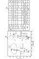
- FIG. 3 is a diagram illustrating an example of clustering by an analysis server;
- FIG. 4 is a flowchart illustrating an example of a processing procedure of an analysis server;
- FIG. 5 is a flowchart illustrating an example of a processing procedure of an analysis server;
- FIG. 6 is a diagram illustrating an example of how an operator responds to an alert using the result of alert clustering by the analysis server.
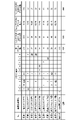
- FIG. 7 is a diagram illustrating an example of the result of alert clustering by the analysis server and the determination result of the same type of alert.
- FIG. 8 is a diagram showing a configuration example of a computer that executes an analysis program.
- the analysis system 1 includes a sensing device 2 and an analysis server 10.
- the sensing device 2 observes communication of terminal equipment (for example, IoT equipment).
- the sensing device 2 observes the communication of the terminal device by mirroring the NW (network) device to which the terminal device is connected. Then, the sensing device 2 generates information (processed information) obtained by processing the communication observation result of the terminal device, generates a communication feature amount from the processed information, and transmits it to the analysis server 10 .
- NW network
- the sensing device 2 generates information (processed information) obtained by processing the communication observation result of the terminal device, generates a communication feature amount from the processed information, and transmits it to the analysis server 10 .
- the feature amounts of the communication are, for example, the IP address of the terminal device performing the communication, the session source IP address, the session destination IP address, the session destination port number, the protocol number, the session duration, This information indicates the total number of forward bytes, the total number of packets in the forward direction, the total number of bytes in the reverse direction, the total number of packets in the reverse direction, and the like.
- the analysis server 10 determines whether or not the communication is normal based on the characteristic amount of the communication transmitted from the sensing device 2 and the model indicating the characteristics of normal communication, and determines that the communication is abnormal. If so, output an alert.
- the analysis server 10 calculates an anomaly score indicating the deviation between the communication feature quantity transmitted from the sensing device 2 and a model indicating the characteristics of normal communication, and if the anomaly score exceeds a predetermined threshold, an alert to output After that, the operator of the analysis system 1 confirms the contents of the alert, and if the alert is overdetection, feeds back to that effect.
- the feedback here is, for example, by the operator registering in the analysis server 10 that the alert is an over-detection, so that the analysis server 10 does not generate an alert for the same type of feature quantity thereafter. is.
- the analysis server 10 performs clustering of alerts so that the characteristics of each cluster can be clearly seen so that the operator can efficiently perform the above-described confirmation work (confirmation work for alerts of the same type can be collectively performed).
- the analysis server 10 when clustering alerts, the analysis server 10 excludes alerts for communications not included in the communication data used for learning the above model (for example, communications by new terminal devices) from clustering targets. .
- the analysis server 10 stores feature amount items (for example, session duration, forward direction total byte count, forward direction total packet count, reverse direction total byte count, reverse direction total packet count, etc.) that tend to reveal communication characteristics. to cluster the alerts.
- feature amount items for example, session duration, forward direction total byte count, forward direction total packet count, reverse direction total byte count, reverse direction total packet count, etc.
- the analysis server 10 can cluster alerts so that the characteristics of each cluster appear clearly.
- the analysis server 10 outputs the determination result as to whether or not each cluster is composed of alerts of the same type.
- the operator can identify clusters that are composed of alerts of the same type and can be completed with a single over-detection determination. As a result, it is possible to reduce the work required to determine whether an alert is due to overdetection.
- the analysis server 10 since the analysis server 10 does not use payload information that depends on a specific payload when clustering alerts, it can also support clustering of encrypted communication alerts.
- the analysis server 10 includes a storage unit 12, a feature amount reception unit 131, a learning unit 132, an analysis unit (accumulation unit) 133, a screen display processing unit 134, a clustering unit 135, a determination unit 136, and a result output. and a portion 137 .
- the storage unit 12 stores information that the analysis server 10 refers to when executing various processes and the execution results of various processes.
- the storage unit 12 stores the feature amount of communication acquired from the sensing device 2, the model indicating the feature of normal communication learned by the learning unit 132, and the communication tuple (initial tuple) of the feature amount used for learning the model.
- communication analysis results for example, the above-mentioned anomaly score
- the communication tuple of the feature amount used for model learning is called an initial tuple.
- the initial tuple is, for example, the IP address of the terminal device, the source IP address of the session, the destination IP address of the session, the destination port number of the session, the protocol number, etc., which are included in the feature amount used for learning the model. Yes, but not limited to the above five.
- the feature amount reception unit 131 receives communication feature amounts from the sensing device 2 . Then, the feature quantity receiving unit 131 accumulates the received communication feature quantity in the storage unit 12 . For example, the feature quantity reception unit 131 first receives a feature quantity of communication for model learning (a feature quantity of normal communication) and stores it in the storage unit 12 . After that, the feature quantity reception unit 131 receives the feature quantity of the communication to be detected, and stores it in the storage unit 12 .
- a feature quantity of communication for model learning a feature quantity of normal communication
- the learning unit 132 uses the feature amount of communication (feature amount of normal communication) accumulated in the storage unit 12 to learn a model that indicates the characteristics of normal communication. After that, the learning unit 132 stores each parameter of the learned model and data used for model learning (for example, an initial tuple) in the storage unit 12 .
- the analysis unit 133 uses the model learned by the learning unit 132 to analyze the communication to be detected. For example, the analysis unit 133 calculates an anomaly score indicating the deviation between the feature amount of the communication to be detected and the above model. Then, the analysis unit 133 outputs an alert when the anomaly score exceeds a predetermined threshold (that is, when there is a high possibility that the communication is not normal).
- the alert includes, for example, identification information of the communication targeted for the alert, date and time of occurrence of the communication, and the like. The output alert is accumulated in the storage unit 12 .
- the screen display processing unit 134 displays the alerts accumulated in the storage unit 12 on the screen. For example, the screen display processing unit 134 displays a list of alerts accumulated in the storage unit 12 on the screen based on the instruction input by the operator. This allows the operator to confirm on the screen what kind of alert has been output.
- the clustering unit 135 performs clustering of alerts based on communication feature amounts included in the alerts accumulated in the storage unit 12 .
- the clustering unit 135 acquires from the storage unit 12 the alert and the feature amount of the communication targeted by the alert. Then, the clustering unit 135 clusters the alerts based on the acquired communication feature amount.
- the clustering unit 135 narrows down and normalizes the items of the feature amount used for clustering among the feature amounts of the communication targeted for the alert so that the feature of each cluster appears clearly.
- the clustering unit 135 excludes alerts of communication tuples that are different from the communication tuples (initial tuples) of the feature values used for model learning from clustering targets. For example, the clustering unit 135 compares the communication tuple (initial tuple) of the feature amount used for model learning with the communication tuple of the communication feature amount included in the alert, and obtains a categorical variable (IP of the terminal device itself). addresses, session source IP addresses, session destination IP addresses, session destination port numbers, and protocol numbers) are excluded from clustering targets.
- IP categorical variable
- the clustering unit 135 can exclude alerts with clear reasons, such as communications from new terminal devices, from clustering targets.
- the clustering unit 135 performs clustering by excluding information such as communication occurrence date and time, anomaly score, etc., from the information included in the alert. For example, the clustering unit 135 determines at least one of the session duration, the total number of forward bytes, the total number of forward packets, the total number of reverse bytes, and the total number of reverse packets among the communication feature amounts included in the alert. to cluster alerts.
- the clustering unit 135 normalizes the difference between the value of the communication feature amount used for learning the model (the value at the time of initial learning) and the value of the communication feature amount included in the alert. clustering of alerts using the converted values.
- the clustering unit 135 determines, for each terminal device, the session duration, total number of forward bytes, total number of forward packets, total number of reverse bytes, and total number of reverse packets among the feature quantities of alert communication. For each, the difference from the value at the time of initial learning is calculated. Then, the clustering unit 135 clusters the alerts using the logarithmically scaled value of the difference (see FIG. 2).
- FIG. 301 An example of the result of clustering by the clustering unit 135 is indicated by reference numeral 301 in FIG.
- the clustering unit 135 generates 165 alerts for five terminal devices (Iot-A, Iot-B, Iot-C, Iot-D, and Iot-E) for session duration, total positive bytes, The results of clustering (cluster 0 to cluster 7) are shown based on the five feature values of the total number of forward packets, the total number of reverse bytes, and the total number of reverse packets.
- reference numeral 301 indicates a state in which the above clustering result is viewed from the direction of the session duration and the backward total number of bytes.
- the clustering algorithm used by the clustering unit 135 is Birch, k-means, etc., for example.
- the user of the analysis server 10 can set what kind of clustering algorithm the clustering unit 135 uses.
- the determination unit 136 determines whether or not each cluster generated by the clustering unit 135 is composed of alerts of the same type.
- the determination unit 136 determines whether each cluster is composed of alerts of the same type based on the ratio of the number of alerts in each cluster to all alerts, the number of terminal devices targeted for alerts in each cluster, the density of each cluster, and the like. determine whether or not there is
- the determination unit 136 calculates the value of (the number of alerts that make up the cluster/the number of all alerts) for each cluster, and classifies clusters that have a predetermined threshold value (for example, 70%) or more as the same type. It is determined that the cluster is configured by the alerts of the alerts of
- the determination unit 136 calculates, for each cluster, how many terminal devices that are alert targets are included in the cluster.
- a certain cluster is determined as a cluster composed of alerts of the same type.
- the determination unit 136 creates a scatter diagram of clusters, calculates the density of the cluster using the area of the cluster on the scatter diagram, and the number of alerts included in the cluster, and the calculated density is , is determined to be a cluster composed of alerts of the same type. For example, the determination unit 136 calculates (the number of alerts that make up the cluster/the area of the cluster) for each cluster, and classifies the clusters whose calculated value is equal to or greater than a predetermined threshold (for example, 1000) as is determined to be a cluster composed of alerts.
- a predetermined threshold for example, 1000
- clusters cluster1 to cluster7
- reference numeral 301 in FIG. For example, for the clusters (cluster1 to cluster7) indicated by reference numeral 301 in FIG. will be described.
- the ratio of the number of alerts in the cluster to the total number of alerts is 70% or more
- the number of terminal devices targeted for alerts in the cluster is 1
- the density of the cluster is 1000 or more
- the information indicated by reference numeral 302 is the number of alerts of each terminal device (Iot-A, Iot-B, Iot-C, Iot-D, Iot-E) for each cluster (cluster0 to cluster7) indicated by reference numeral 301, This is information indicating area and density.
- cluster 0 is a cluster of Iot-C alerts only and has a density of 1000 or more.
- Cluster 3 is also a cluster of Iot-E alerts only and has a density of 1000 or more. Therefore, the determination unit 136 determines that cluster0 and cluster3 are clusters composed of alerts of the same type.
- the result output unit 137 outputs the result of clustering by the clustering unit 135 and the result of determination by the determination unit 136 as to whether or not each cluster is composed of alerts of the same type.
- the result output unit 137 outputs the result of clustering indicated by reference numeral 301 in FIG. information and output.
- an analysis server 10 when clustering alerts, it is possible to generate clusters that clearly show the characteristics of each cluster. Also, the analysis server 10 outputs the determination result as to whether or not each cluster is composed of the same type of alert. This allows the operator to identify clusters for which a single over-detection determination is sufficient. As a result, it is possible to reduce the work required to determine whether an alert is due to overdetection.
- FIG. 1 An example of the processing procedure of the analysis server 10 will be described with reference to FIGS. 4 and 5.
- FIG. First, the process of accumulating alerts by the analysis server 10 will be described with reference to FIG. 4, and then the process of clustering the accumulated alerts by the analysis server 10 will be described with reference to FIG.
- the feature quantity reception unit 131 of the analysis server 10 accumulates the feature quantity of communication (the feature quantity of normal communication) transmitted from the sensing device 2 in the storage unit 12 (S1 in FIG. 4).
- the learning unit 132 performs learning (initial learning) of a model indicating the characteristics of normal communication using the communication feature amounts accumulated in S1 (S2).
- the feature quantity reception unit 131 accumulates the feature quantity of the communication to be detected in the storage unit 12 (S3). Then, the analysis unit 133 calculates an anomaly score indicating the deviation between the feature quantity of the communication to be detected and the model learned in S2 (S4).
- the analysis unit 133 determines that the anomaly score calculated in S4 exceeds the predetermined threshold (Yes in S5), it generates an alert for the communication and stores it in the storage unit 12 (S6). If the processing has not yet been executed for any detection target communication (No in S7), the analysis server 10 executes the processing from S4 onward for the detection target communication for which processing has not yet been executed. do. On the other hand, if the processing has already been executed for all detection target communications (Yes in S7), the analysis server 10 ends the processing.
- the analysis unit 133 determines that the anomaly score calculated in S4 is equal to or less than a predetermined threshold (No in S5), and if processing has not been executed for any of the detection target communications (No in S7), The processing from S4 onwards is executed for the detection target communication for which processing has not yet been executed.
- the clustering unit 135 of the analysis server 10 excludes, from alerts accumulated in the storage unit 12, alerts of communication tuples different from the communication tuples (initial tuples) of the feature values used for model learning, from clustering targets. (S11 in FIG. 5).
- the clustering unit 135 compares the communication tuple (initial tuple) used for learning the model with the communication tuple of the communication feature amount included in the alert, and compares the initial tuple with the categorical variables (terminal device IP address, session (combination of source IP address of session, destination IP address of session, destination port number of session, and protocol number)) are excluded from clustering targets.
- the clustering unit 135 After S11, the clustering unit 135 performs session duration, total number of forward bytes, total number of forward packets, total number of reverse bytes, and total number of reverse packets among the communication feature amounts included in the alert, Alerts are clustered (S12).
- the determination unit 136 determines whether or not each cluster generated by clustering in S12 is composed of alerts of the same type (S13).
- the determination unit 136 determines whether each cluster is composed of alerts of the same type based on the ratio of the number of alerts in each cluster to all alerts, the number of terminal devices targeted for alerts in each cluster, the density of each cluster, and the like. determine whether or not there is
- the result output unit 137 outputs the clustering result of S12 and the determination result of whether or not each cluster in S13 is composed of alerts of the same type (S14).
- the analysis server 10 clusters the alert and determines whether or not each cluster consists of alerts of the same type (S101: clustering).
- the operator confirms the alerts using the result of clustering the alerts described above and the determination result of whether or not each cluster is composed of the same type of alerts. For example, the operator performs the alert confirmation process shown in S102 to S108 for each alert or for each cluster until there are no more unconfirmed alerts.
- the operator confirms whether or not the communication pattern targeted for the alert is a new communication pattern that did not exist during model learning (S102). Further, the operator confirms whether or not the communication parameter to be alerted is a new communication parameter of the learned communication pattern (S103). Based on the confirmation result, the operator makes an inquiry to the department in charge of the terminal device that is the target of the alert (S104). As a result of the inquiry, if there is an abnormality in the terminal device (Yes in S105), the operator takes measures according to the abnormality (S106). Then, the alert confirmation process ends. After that, the analysis server 10 continues monitoring.
- the operator determines whether the alert is due to overdetection (S107). Then, when the operator determines that the alert is due to overdetection (Yes in S107), the overdetection is fed back (S108). At this time, the operator collectively provides over-detection feedback for clusters of alerts of the same type.
- the analysis server 10 then continues monitoring the communication of the terminal device.
- the analysis server 10 outputs the alert clustering result and the determination result as to whether or not each cluster is composed of alerts of the same type. It is possible to judge overdetection in units and implement feedback. As a result, it is possible to reduce the work required to determine whether an alert is due to overdetection.
- the analysis server 10 applies two types of loads with small positive differentials (10 0.2 times, 10 0.4 times) and four types of loads with large positive differentials (10 1 times, 10 1.2 times, 10 1.4 times, 10 1.6 times), 3 types of loads with small negative difference (10 -0.2 times, 10 -0.4 times, 10 -0.6 times), difference communication tuple load (difference due to categorical variables ) applied 10 patterns of loads (changes to communication) and generated alerts.
- the analysis server 10 uses Birch as an alert clustering algorithm, and the maximum number of clusters is set to 10.
- FIG. 7 shows the result of clustering alerts related to the above 10 patterns of communication by the analysis server 10 .
- 643 alerts were included in the largest cluster with an alert ratio exceeding 70%.
- the analysis server 10 determines that the maximum cluster in which the alert ratio exceeds 70% is a cluster composed of alerts of the same type, and outputs the determination result so that the operator can detect overdetection of the cluster. judgment can be made collectively. As a result, the above 643 alerts are compressed to 9 alerts (1 for each load), so the number of cases that operators judge to be overdetection is reduced from 939 to 305 (67.5% decrease). ).
- each constituent element of each part shown in the figure is functionally conceptual, and does not necessarily need to be physically configured as shown in the figure.
- the specific form of distribution and integration of each device is not limited to the illustrated one, and all or part of them can be functionally or physically distributed and integrated in arbitrary units according to various loads and usage conditions. Can be integrated and configured.
- all or any part of each processing function performed by each device can be implemented by a CPU and a program executed by the CPU, or implemented as hardware based on wired logic.
- the analysis server 10 described above can be implemented by installing a program as package software or online software on a desired computer.
- the information processing device can function as the analysis server 10 by causing the information processing device to execute the above program.
- the information processing apparatus referred to here includes a desktop or notebook personal computer.
- information processing devices include mobile communication terminals such as smartphones, mobile phones and PHS (Personal Handyphone Systems), and terminals such as PDAs (Personal Digital Assistants).
- the analysis server 10 can also be implemented as a server device that uses a terminal device used by a user as a client and provides the client with services related to the above processing.
- the server device may be implemented as a web server, or may be implemented as a cloud that provides services related to the above processing by outsourcing.
- FIG. 8 is a diagram showing an example of a computer that executes an analysis program.
- the computer 1000 has a memory 1010 and a CPU 1020, for example.
- Computer 1000 also has hard disk drive interface 1030 , disk drive interface 1040 , serial port interface 1050 , video adapter 1060 and network interface 1070 . These units are connected by a bus 1080 .
- the memory 1010 includes a ROM (Read Only Memory) 1011 and a RAM (Random Access Memory) 1012 .
- the ROM 1011 stores a boot program such as BIOS (Basic Input Output System).
- BIOS Basic Input Output System
- Hard disk drive interface 1030 is connected to hard disk drive 1090 .
- a disk drive interface 1040 is connected to the disk drive 1100 .
- a removable storage medium such as a magnetic disk or optical disk is inserted into the disk drive 1100 .
- Serial port interface 1050 is connected to mouse 1110 and keyboard 1120, for example.
- Video adapter 1060 is connected to display 1130, for example.
- the hard disk drive 1090 stores, for example, an OS 1091, application programs 1092, program modules 1093, and program data 1094. That is, the program defining each process executed by the analysis server 10 is implemented as a program module 1093 in which computer-executable code is described. Program modules 1093 are stored, for example, on hard disk drive 1090 . For example, a program module 1093 for executing processing similar to the functional configuration in the analysis server 10 is stored in the hard disk drive 1090 .
- the hard disk drive 1090 may be replaced by an SSD (Solid State Drive).
- the data used in the processes of the above-described embodiments are stored as program data 1094 in the memory 1010 or the hard disk drive 1090, for example. Then, the CPU 1020 reads out the program modules 1093 and program data 1094 stored in the memory 1010 and the hard disk drive 1090 to the RAM 1012 as necessary and executes them.
- the program modules 1093 and program data 1094 are not limited to being stored in the hard disk drive 1090, but may be stored in a removable storage medium, for example, and read by the CPU 1020 via the disk drive 1100 or the like. Alternatively, the program modules 1093 and program data 1094 may be stored in another computer connected via a network (LAN (Local Area Network), WAN (Wide Area Network), etc.). Program modules 1093 and program data 1094 may then be read by CPU 1020 through network interface 1070 from other computers.
- LAN Local Area Network
- WAN Wide Area Network
- analysis system 2 sensing device 10 analysis server 12 storage unit 131 feature amount reception unit 132 learning unit 133 analysis unit (accumulation unit) 134 Screen display processing unit 135 Clustering unit 136 Judgment unit 137 Result output unit
Landscapes
- Engineering & Computer Science (AREA)
- Theoretical Computer Science (AREA)
- General Engineering & Computer Science (AREA)
- Computer Networks & Wireless Communication (AREA)
- Signal Processing (AREA)
- Quality & Reliability (AREA)
- Physics & Mathematics (AREA)
- General Physics & Mathematics (AREA)
- Computer Hardware Design (AREA)
- Data Exchanges In Wide-Area Networks (AREA)
- Analysing Materials By The Use Of Radiation (AREA)
- Investigating Or Analysing Biological Materials (AREA)
Abstract
Description
まず、図1を参照しながら、分析サーバ(分析装置)10を含む分析システム1の動作概要を説明する。
次に、図1を参照しながら、分析サーバ10の構成例を説明する。分析サーバ10は、記憶部12と、特徴量受付部131と、学習部132と、分析部(蓄積部)133と、画面表示処理部134と、クラスタリング部135と、判定部136と、結果出力部137とを備える。
(2)当該クラスタにおけるアラートの対象となった端末機器の数が1台
(3)当該クラスタの密度が1000以上
次に、図4、図5を用いて、分析サーバ10の処理手順の例を説明する。まず、図4を用いて、分析サーバ10がアラートを蓄積する処理を説明し、次に、図5を用いて、分析サーバ10が蓄積されたアラートのクラスタリングを行う処理を説明する。
次に、図6を用いて、分析サーバ10が出力した、アラートのクラスタリングの結果と、クラスタそれぞれが同種のアラートにより構成されているか否かの判定結果とを用いた、運用者によるアラートの対応例について説明する。
次に、図7を用いて、分析サーバ10による、アラートのクラスタリングの実験結果を説明する。ここでは、分析サーバ10が、処理対象とする通信に、正常状態の通信と比較して、正差分の小さな負荷2種類(100.2倍、100.4倍)、正差分の大きな負荷4種類(101倍、101.2倍、101.4倍、101.6倍)、負差分の小さな負荷3種類(10-0.2倍、10-0.4倍、10-0.6倍)、相違通信タプルの負荷(カテゴリ変数による差異)の10パターンの負荷(通信に対する変更)を印加し、アラートを生成した。また、分析サーバ10は、アラートのクラスタリングアルゴリズムにBirchを用い、クラスタ数は最大で10個となるよう設定した。
また、図示した各部の各構成要素は機能概念的なものであり、必ずしも物理的に図示のように構成されていることを要しない。すなわち、各装置の分散・統合の具体的形態は図示のものに限られず、その全部又は一部を、各種の負荷や使用状況等に応じて、任意の単位で機能的又は物理的に分散・統合して構成することができる。さらに、各装置にて行われる各処理機能は、その全部又は任意の一部が、CPU及び当該CPUにて実行されるプログラムにて実現され、あるいは、ワイヤードロジックによるハードウェアとして実現され得る。
前記した分析サーバ10は、パッケージソフトウェアやオンラインソフトウェアとしてプログラムを所望のコンピュータにインストールさせることによって実装できる。例えば、上記のプログラムを情報処理装置に実行させることにより、情報処理装置を分析サーバ10として機能させることができる。ここで言う情報処理装置には、デスクトップ型又はノート型のパーソナルコンピュータが含まれる。また、その他にも、情報処理装置にはスマートフォン、携帯電話機やPHS(Personal Handyphone System)等の移動体通信端末、さらには、PDA(Personal Digital Assistant)等の端末等がその範疇に含まれる。
2 センシング装置
10 分析サーバ
12 記憶部
131 特徴量受付部
132 学習部
133 分析部(蓄積部)
134 画面表示処理部
135 クラスタリング部
136 判定部
137 結果出力部
Claims (9)
- 正常な通信の特徴を示すモデルに基づき、正常な通信ではないと判定された通信のアラートを蓄積する蓄積部と、
前記蓄積されたアラートに含まれる通信の特徴量を用いて、前記アラートのクラスタリングを行うクラスタリング部と、
前記クラスタリングにより生成されたクラスタそれぞれについて、前記クラスタが同種のアラートにより構成されているか否かを判定する判定部と、
前記クラスタリングの結果と、前記クラスタそれぞれが同種のアラートにより構成されているか否かの判定結果とを出力する結果出力部と、
を備えることを特徴とする分析装置。 - 前記クラスタリング部は、
前記モデルの学習に用いた通信の特徴量と、前記アラートに含まれる通信の特徴量とを比較し、前記通信の端末機器のIPアドレス、セッションの送信元IPアドレス、セッションの送信先IPアドレス、セッションの送信先ポート番号およびプロトコル番号の組み合わせが異なるアラートを、前記クラスタリングの対象から除いてクラスタリングを行うこと
を特徴とする請求項1に記載の分析装置。 - 前記クラスタリング部は、
前記アラートに含まれる通信の特徴量のうち、セッション持続時間、正方向総バイト数、正方向総パケット数、逆方向総バイト数および逆方向総パケット数の少なくともいずれかを用いて、前記アラートのクラスタリングを行うこと
を特徴とする請求項1に記載の分析装置。 - 前記クラスタリング部は、
端末機器ごとに、前記モデルの学習に用いられた通信の特徴量の値と、前記アラートに含まれる当該通信の特徴量の値との差分を算出し、前記特徴量の差分の値を対数スケールに変換した値を用いて、前記アラートのクラスタリングを行うこと
を特徴とする請求項1に記載の分析装置。 - 前記判定部は、
前記生成されたクラスタごとに、当該クラスタを構成するアラートの数の、全アラートの数に対する比率が、所定の閾値以上のクラスタを、同種のアラートのアラートにより構成されるクラスタと判定する
ことを特徴とする請求項1に記載の分析装置。 - 前記判定部は、
前記生成されたクラスタごとに、当該クラスタにアラートの対象となった端末機器が何台含まれるかを算出し、前記算出した台数が、所定の閾値以下であるクラスタを、同種のアラートのアラートにより構成されるクラスタと判定する
ことを特徴とする請求項1に記載の分析装置。 - 前記判定部は、
前記生成されたクラスタの散布図を作成し、前記散布図上のクラスタの面積と、当該クラスタに含まれるアラート数とを用いて、当該クラスタの密度を算出し、前記算出した密度が、所定の閾値以上のクラスタを、同種のアラートから構成されるクラスタと判定する ことを特徴とする請求項1に記載の分析装置。 - 分析装置により実行される分析方法であって、
正常な通信の特徴を示すモデルに基づき、正常な通信ではないと判定された通信のアラートを蓄積する工程と、
前記蓄積されたアラートに含まれる通信の特徴量を用いて、前記アラートのクラスタリングを行うクラスタリングを行う工程と、
前記クラスタリングにより生成されたクラスタそれぞれについて、前記クラスタが同種のアラートにより構成されているか否かを判定する工程と、
前記クラスタリングの結果と、前記クラスタそれぞれが同種のアラートにより構成されているか否かの判定結果とを出力する工程と、
を含むことを特徴とする分析方法。 - 正常な通信の特徴を示すモデルに基づき、正常な通信ではないと判定された通信のアラートを蓄積する工程と、
前記蓄積されたアラートに含まれる通信の特徴量を用いて、前記アラートのクラスタリングを行うクラスタリングを行う工程と、
前記クラスタリングにより生成されたクラスタそれぞれについて、前記クラスタが同種のアラートにより構成されているか否かを判定する工程と、
前記クラスタリングの結果と、前記クラスタそれぞれが同種のアラートにより構成されているか否かの判定結果とを出力する工程と、
をコンピュータに実行させるための分析プログラム。
Priority Applications (6)
| Application Number | Priority Date | Filing Date | Title |
|---|---|---|---|
| JP2023526786A JP7582469B2 (ja) | 2021-06-10 | 2021-06-10 | 分析装置、分析方法、および、分析プログラム |
| CN202180098639.6A CN117397218A (zh) | 2021-06-10 | 2021-06-10 | 分析装置、分析方法以及分析程序 |
| US18/566,582 US12524292B2 (en) | 2021-06-10 | 2021-06-10 | Analysis device, analysis method, and analysis program |
| PCT/JP2021/022220 WO2022259496A1 (ja) | 2021-06-10 | 2021-06-10 | 分析装置、分析方法、および、分析プログラム |
| EP21945170.5A EP4333377A4 (en) | 2021-06-10 | 2021-06-10 | ANALYSIS DEVICE, METHOD AND PROGRAM |
| AU2021450034A AU2021450034B2 (en) | 2021-06-10 | 2021-06-10 | Analysis device, analysis method, and analysis program |
Applications Claiming Priority (1)
| Application Number | Priority Date | Filing Date | Title |
|---|---|---|---|
| PCT/JP2021/022220 WO2022259496A1 (ja) | 2021-06-10 | 2021-06-10 | 分析装置、分析方法、および、分析プログラム |
Publications (1)
| Publication Number | Publication Date |
|---|---|
| WO2022259496A1 true WO2022259496A1 (ja) | 2022-12-15 |
Family
ID=84425081
Family Applications (1)
| Application Number | Title | Priority Date | Filing Date |
|---|---|---|---|
| PCT/JP2021/022220 Ceased WO2022259496A1 (ja) | 2021-06-10 | 2021-06-10 | 分析装置、分析方法、および、分析プログラム |
Country Status (6)
| Country | Link |
|---|---|
| US (1) | US12524292B2 (ja) |
| EP (1) | EP4333377A4 (ja) |
| JP (1) | JP7582469B2 (ja) |
| CN (1) | CN117397218A (ja) |
| AU (1) | AU2021450034B2 (ja) |
| WO (1) | WO2022259496A1 (ja) |
Cited By (1)
| Publication number | Priority date | Publication date | Assignee | Title |
|---|---|---|---|---|
| WO2024171457A1 (ja) * | 2023-02-17 | 2024-08-22 | 日本電信電話株式会社 | 情報処理装置、情報処理方法および情報処理プログラム |
Citations (6)
| Publication number | Priority date | Publication date | Assignee | Title |
|---|---|---|---|---|
| WO2016208158A1 (ja) * | 2015-06-26 | 2016-12-29 | 日本電気株式会社 | 情報処理装置、情報処理システム、情報処理方法、及び、記憶媒体 |
| JP2017509262A (ja) * | 2014-03-24 | 2017-03-30 | マイクロソフト テクノロジー ライセンシング,エルエルシー | ネットワーク障害のトラブルシューティング・オプションの識別 |
| JP2017111796A (ja) * | 2015-12-16 | 2017-06-22 | パナソニック インテレクチュアル プロパティ コーポレーション オブ アメリカPanasonic Intellectual Property Corporation of America | セキュリティ処理方法及びサーバ |
| JP2020005184A (ja) | 2018-06-29 | 2020-01-09 | 日本電信電話株式会社 | 通信システム及び通信方法 |
| JP2020135655A (ja) | 2019-02-22 | 2020-08-31 | 日本電信電話株式会社 | 通信端末装置、通信制御方法及び通信制御プログラム |
| CN112600792A (zh) * | 2020-11-23 | 2021-04-02 | 国网山东省电力公司青岛供电公司 | 一种物联网设备的异常行为检测方法及系统 |
Family Cites Families (7)
| Publication number | Priority date | Publication date | Assignee | Title |
|---|---|---|---|---|
| US10311455B2 (en) * | 2004-07-08 | 2019-06-04 | One Network Enterprises, Inc. | Computer program product and method for sales forecasting and adjusting a sales forecast |
| CN104937933A (zh) * | 2013-09-09 | 2015-09-23 | 奥林巴斯株式会社 | 画像显示装置、编码方法以及编码程序 |
| US9099162B2 (en) * | 2013-10-31 | 2015-08-04 | Oracle International Corporation | Media and drive validation in tape libraries |
| US10282458B2 (en) * | 2015-06-15 | 2019-05-07 | Vmware, Inc. | Event notification system with cluster classification |
| AU2019201137B2 (en) * | 2018-02-20 | 2023-11-16 | Darktrace Holdings Limited | A cyber security appliance for a cloud infrastructure |
| US11539595B1 (en) * | 2020-02-28 | 2022-12-27 | Amazon Technologies, Inc. | Tracking cluster identity over time |
| US20210326744A1 (en) * | 2020-04-17 | 2021-10-21 | Microsoft Technology Licensing, Llc | Security alert-incident grouping based on investigation history |
-
2021
- 2021-06-10 CN CN202180098639.6A patent/CN117397218A/zh active Pending
- 2021-06-10 WO PCT/JP2021/022220 patent/WO2022259496A1/ja not_active Ceased
- 2021-06-10 JP JP2023526786A patent/JP7582469B2/ja active Active
- 2021-06-10 EP EP21945170.5A patent/EP4333377A4/en active Pending
- 2021-06-10 AU AU2021450034A patent/AU2021450034B2/en active Active
- 2021-06-10 US US18/566,582 patent/US12524292B2/en active Active
Patent Citations (6)
| Publication number | Priority date | Publication date | Assignee | Title |
|---|---|---|---|---|
| JP2017509262A (ja) * | 2014-03-24 | 2017-03-30 | マイクロソフト テクノロジー ライセンシング,エルエルシー | ネットワーク障害のトラブルシューティング・オプションの識別 |
| WO2016208158A1 (ja) * | 2015-06-26 | 2016-12-29 | 日本電気株式会社 | 情報処理装置、情報処理システム、情報処理方法、及び、記憶媒体 |
| JP2017111796A (ja) * | 2015-12-16 | 2017-06-22 | パナソニック インテレクチュアル プロパティ コーポレーション オブ アメリカPanasonic Intellectual Property Corporation of America | セキュリティ処理方法及びサーバ |
| JP2020005184A (ja) | 2018-06-29 | 2020-01-09 | 日本電信電話株式会社 | 通信システム及び通信方法 |
| JP2020135655A (ja) | 2019-02-22 | 2020-08-31 | 日本電信電話株式会社 | 通信端末装置、通信制御方法及び通信制御プログラム |
| CN112600792A (zh) * | 2020-11-23 | 2021-04-02 | 国网山东省电力公司青岛供电公司 | 一种物联网设备的异常行为检测方法及系统 |
Non-Patent Citations (2)
| Title |
|---|
| IHARA, TOSHIHIR O: "Utilization of case studies", K- OPTICOM, 15 September 2016 (2016-09-15), pages 54 - 57 * |
| See also references of EP4333377A4 |
Cited By (1)
| Publication number | Priority date | Publication date | Assignee | Title |
|---|---|---|---|---|
| WO2024171457A1 (ja) * | 2023-02-17 | 2024-08-22 | 日本電信電話株式会社 | 情報処理装置、情報処理方法および情報処理プログラム |
Also Published As
| Publication number | Publication date |
|---|---|
| AU2021450034B2 (en) | 2024-11-21 |
| US20240256376A1 (en) | 2024-08-01 |
| US12524292B2 (en) | 2026-01-13 |
| AU2021450034A1 (en) | 2023-12-07 |
| CN117397218A (zh) | 2024-01-12 |
| JP7582469B2 (ja) | 2024-11-13 |
| EP4333377A1 (en) | 2024-03-06 |
| EP4333377A4 (en) | 2025-03-05 |
| JPWO2022259496A1 (ja) | 2022-12-15 |
Similar Documents
| Publication | Publication Date | Title |
|---|---|---|
| US20240232357A1 (en) | Multi-step approach for ransomware detection | |
| US10860406B2 (en) | Information processing device and monitoring method | |
| US20220368706A1 (en) | Attack Behavior Detection Method and Apparatus, and Attack Detection Device | |
| WO2022176128A1 (ja) | 分析装置、分析システム、分析方法、および、分析プログラム | |
| US20240320329A1 (en) | Machine Learning Model Adversarial Attack Monitoring | |
| US20070289013A1 (en) | Method and system for anomaly detection using a collective set of unsupervised machine-learning algorithms | |
| CN112073389A (zh) | 云主机安全态势感知系统、方法、设备及存储介质 | |
| WO2007129027A1 (en) | Data processing method for controlling a network | |
| US10033610B2 (en) | Metric driven holistic network management system | |
| US20180375880A1 (en) | Malicious industrial internet of things node activity detection for connected plants | |
| CN110389873A (zh) | 一种判定服务器资源使用情况的方法和装置 | |
| CN101833575B (zh) | 一种网络病毒报告排序方法 | |
| US10389641B2 (en) | Network operation | |
| WO2022259496A1 (ja) | 分析装置、分析方法、および、分析プログラム | |
| WO2024115310A1 (en) | Monitoring system | |
| Buttyán et al. | Simbiota++: improved similarity-based IoT malware detection | |
| CN114363148B (zh) | 一种检测攻击告警的方法、装置、检测设备及存储介质 | |
| CN112583825B (zh) | 一种工业系统的异常检测方法和装置 | |
| JP7184197B2 (ja) | 異常検出装置、異常検出方法および異常検出プログラム | |
| CN114650218B (zh) | 一种数据获取方法、设备、系统及存储介质 | |
| JP2019004284A (ja) | 異常検出装置、および、異常検出方法 | |
| WO2022195887A1 (ja) | トラフィックセンサ、分析方法、および、分析プログラム | |
| JP7800687B2 (ja) | 異常検出装置、異常検出方法および異常検出プログラム | |
| WO2021084664A1 (ja) | 抽出装置、抽出方法及び抽出プログラム | |
| CN118368195B (zh) | 一种基于大数据的机房网络性能优化方法及系统 |
Legal Events
| Date | Code | Title | Description |
|---|---|---|---|
| WWE | Wipo information: entry into national phase |
Ref document number: 2023526786 Country of ref document: JP |
|
| WWE | Wipo information: entry into national phase |
Ref document number: 2021450034 Country of ref document: AU Ref document number: AU2021450034 Country of ref document: AU |
|
| WWE | Wipo information: entry into national phase |
Ref document number: 202180098639.6 Country of ref document: CN |
|
| WWE | Wipo information: entry into national phase |
Ref document number: 2021945170 Country of ref document: EP Ref document number: 21945170.5 Country of ref document: EP |
|
| WWE | Wipo information: entry into national phase |
Ref document number: 18566582 Country of ref document: US |
|
| ENP | Entry into the national phase |
Ref document number: 2021450034 Country of ref document: AU Date of ref document: 20210610 Kind code of ref document: A |
|
| ENP | Entry into the national phase |
Ref document number: 2021945170 Country of ref document: EP Effective date: 20231129 |
|
| NENP | Non-entry into the national phase |
Ref country code: DE |
|
| WWG | Wipo information: grant in national office |
Ref document number: 18566582 Country of ref document: US |