WO2022265085A1 - 浄化機器の制御方法及び装置、浄化機器 - Google Patents
浄化機器の制御方法及び装置、浄化機器 Download PDFInfo
- Publication number
- WO2022265085A1 WO2022265085A1 PCT/JP2022/024223 JP2022024223W WO2022265085A1 WO 2022265085 A1 WO2022265085 A1 WO 2022265085A1 JP 2022024223 W JP2022024223 W JP 2022024223W WO 2022265085 A1 WO2022265085 A1 WO 2022265085A1
- Authority
- WO
- WIPO (PCT)
- Prior art keywords
- concentration distribution
- particulate matter
- indoor space
- control method
- different particle
- Prior art date
- Legal status (The legal status is an assumption and is not a legal conclusion. Google has not performed a legal analysis and makes no representation as to the accuracy of the status listed.)
- Ceased
Links
Images









Classifications
-
- F—MECHANICAL ENGINEERING; LIGHTING; HEATING; WEAPONS; BLASTING
- F24—HEATING; RANGES; VENTILATING
- F24F—AIR-CONDITIONING; AIR-HUMIDIFICATION; VENTILATION; USE OF AIR CURRENTS FOR SCREENING
- F24F11/00—Control or safety arrangements
- F24F11/62—Control or safety arrangements characterised by the type of control or by internal processing, e.g. using fuzzy logic, adaptive control or estimation of values
- F24F11/63—Electronic processing
-
- F—MECHANICAL ENGINEERING; LIGHTING; HEATING; WEAPONS; BLASTING
- F24—HEATING; RANGES; VENTILATING
- F24F—AIR-CONDITIONING; AIR-HUMIDIFICATION; VENTILATION; USE OF AIR CURRENTS FOR SCREENING
- F24F8/00—Treatment, e.g. purification, of air supplied to human living or working spaces otherwise than by heating, cooling, humidifying or drying
- F24F8/10—Treatment, e.g. purification, of air supplied to human living or working spaces otherwise than by heating, cooling, humidifying or drying by separation, e.g. by filtering
- F24F8/108—Treatment, e.g. purification, of air supplied to human living or working spaces otherwise than by heating, cooling, humidifying or drying by separation, e.g. by filtering using dry filter elements
-
- F—MECHANICAL ENGINEERING; LIGHTING; HEATING; WEAPONS; BLASTING
- F24—HEATING; RANGES; VENTILATING
- F24F—AIR-CONDITIONING; AIR-HUMIDIFICATION; VENTILATION; USE OF AIR CURRENTS FOR SCREENING
- F24F11/00—Control or safety arrangements
- F24F11/62—Control or safety arrangements characterised by the type of control or by internal processing, e.g. using fuzzy logic, adaptive control or estimation of values
- F24F11/63—Electronic processing
- F24F11/64—Electronic processing using pre-stored data
-
- F—MECHANICAL ENGINEERING; LIGHTING; HEATING; WEAPONS; BLASTING
- F24—HEATING; RANGES; VENTILATING
- F24F—AIR-CONDITIONING; AIR-HUMIDIFICATION; VENTILATION; USE OF AIR CURRENTS FOR SCREENING
- F24F11/00—Control or safety arrangements
- F24F11/30—Control or safety arrangements for purposes related to the operation of the system, e.g. for safety or monitoring
-
- F—MECHANICAL ENGINEERING; LIGHTING; HEATING; WEAPONS; BLASTING
- F24—HEATING; RANGES; VENTILATING
- F24F—AIR-CONDITIONING; AIR-HUMIDIFICATION; VENTILATION; USE OF AIR CURRENTS FOR SCREENING
- F24F11/00—Control or safety arrangements
- F24F11/70—Control systems characterised by their outputs; Constructional details thereof
- F24F11/72—Control systems characterised by their outputs; Constructional details thereof for controlling the supply of treated air, e.g. its pressure
- F24F11/79—Control systems characterised by their outputs; Constructional details thereof for controlling the supply of treated air, e.g. its pressure for controlling the direction of the supplied air
-
- F—MECHANICAL ENGINEERING; LIGHTING; HEATING; WEAPONS; BLASTING
- F24—HEATING; RANGES; VENTILATING
- F24F—AIR-CONDITIONING; AIR-HUMIDIFICATION; VENTILATION; USE OF AIR CURRENTS FOR SCREENING
- F24F2110/00—Control inputs relating to air properties
- F24F2110/10—Temperature
-
- F—MECHANICAL ENGINEERING; LIGHTING; HEATING; WEAPONS; BLASTING
- F24—HEATING; RANGES; VENTILATING
- F24F—AIR-CONDITIONING; AIR-HUMIDIFICATION; VENTILATION; USE OF AIR CURRENTS FOR SCREENING
- F24F2110/00—Control inputs relating to air properties
- F24F2110/20—Humidity
-
- F—MECHANICAL ENGINEERING; LIGHTING; HEATING; WEAPONS; BLASTING
- F24—HEATING; RANGES; VENTILATING
- F24F—AIR-CONDITIONING; AIR-HUMIDIFICATION; VENTILATION; USE OF AIR CURRENTS FOR SCREENING
- F24F2110/00—Control inputs relating to air properties
- F24F2110/50—Air quality properties
- F24F2110/64—Airborne particle content
-
- F—MECHANICAL ENGINEERING; LIGHTING; HEATING; WEAPONS; BLASTING
- F24—HEATING; RANGES; VENTILATING
- F24F—AIR-CONDITIONING; AIR-HUMIDIFICATION; VENTILATION; USE OF AIR CURRENTS FOR SCREENING
- F24F2110/00—Control inputs relating to air properties
- F24F2110/50—Air quality properties
- F24F2110/65—Concentration of specific substances or contaminants
-
- Y—GENERAL TAGGING OF NEW TECHNOLOGICAL DEVELOPMENTS; GENERAL TAGGING OF CROSS-SECTIONAL TECHNOLOGIES SPANNING OVER SEVERAL SECTIONS OF THE IPC; TECHNICAL SUBJECTS COVERED BY FORMER USPC CROSS-REFERENCE ART COLLECTIONS [XRACs] AND DIGESTS
- Y02—TECHNOLOGIES OR APPLICATIONS FOR MITIGATION OR ADAPTATION AGAINST CLIMATE CHANGE
- Y02B—CLIMATE CHANGE MITIGATION TECHNOLOGIES RELATED TO BUILDINGS, e.g. HOUSING, HOUSE APPLIANCES OR RELATED END-USER APPLICATIONS
- Y02B30/00—Energy efficient heating, ventilation or air conditioning [HVAC]
- Y02B30/70—Efficient control or regulation technologies, e.g. for control of refrigerant flow, motor or heating
Definitions
- the present invention relates to the field of air purification, and more particularly to a control method and device for purification equipment, and a purification equipment.
- Particulate matter in the atmosphere is one of the main pollutants in indoor air and affects the health of people indoors.
- Conventional air purification technology and air purifier products often focus only on the total number of particulate matter in a room.
- the air volume can be adjusted to achieve the purpose of rapidly purifying the indoor air.
- Patent Document 1 discloses an air purifier that changes the amount of air flow from the air blower, the position of the panel, and the area of the ventilation window by detecting the target particle size in the detection area.
- Patent Document 2 discloses an air purifier that adjusts the blowing angle and air volume until an optimum state is reached by detecting indoor information such as the indoor area, obstacles, and distance from the wall.
- Patent Document 3 by comparing the concentration of contaminants to a preset range in only one hour, different operating modes are identified, including different ranges of wind speed switching mode, power on mode, and power off mode.
- a control system and method for a purification device is disclosed.
- Patent Document 4 even when the air pollution concentration is detected and it is determined that the comfort level of the air quality is good, the current air quality situation can be displayed in real time, and at the same time, the motor and buzzer , the auxiliary function part, and the auxiliary function display part on the display screen of the air purifier are all in a non-operating state, but when the air quality deteriorates, the operation of the operating member in the air purifier is resumed, so that the current air purifier discloses an energy-saving control method for an air purifier in which the two states of a simple operating state and a stopped state are improved.
- the air purifier uses only the diameter of the particulate matter to be detected that is output from the contamination detection unit and the diameter of the particulate matter to be detected that has passed through the detection area, and the output of the blower unit It changes the Variations in the distribution of particulate matter with different particle sizes within the chamber are not taken into account. For example, since the particulate matter in the detection area has been clarified, only small-sized particulate matter is present in the detection area around the clarifier, while large amounts of large-sized particulate matter are present in other areas. do. In that case, the air volume controlled by the controller, the position of the panel, and the area of the ventilation window do not match the actual distribution of the particulate matter in the room, and a thorough purification effect cannot be obtained.
- the air purifier adjusts the angle of blowing air from the outlet and adjusts the air volume based on the information detected in the room by the external detection device, by changing the air guide device.
- the air guide device no consideration is given to the distribution of particulate matter in the room.
- the air volume remains unchanged, the air outlet becomes small, and the air velocity increases, the person feels uncomfortable, and at the same time, the purification area becomes smaller.
- Patent Document 3 the current concentration data of pollutants is used to control the air purifier to be in different modes.
- the processing speed is slow, and the energy saving performance of the equipment is poor.
- Patent Document 4 air purifiers are controlled by judging the comfort level of air quality based on the concentration of air pollution detected in real time.
- the processing speed is slow and the energy saving performance of the equipment is poor.
- embodiments of the present invention provide a control method and apparatus for a purification device, a purification device, and a concentration distribution of particulate matter having different particle sizes in an indoor space.
- a control method and apparatus for a purification device it is possible to perform targeted control on particulate matter with different particle diameters, so that the purification efficiency and speed can be improved, and a good purification effect can be achieved quickly and efficiently.
- the step of identifying the concentration distribution of particulate matter having different particle sizes in an indoor space, and depending on the concentration distribution of particulate matter having different particle sizes in the indoor space a method of controlling a purification device comprising controlling at least one device parameter of the purification device.
- obtaining environmental parameters of an indoor space predicting the concentration distribution of pollutants at a plurality of times after the current time based on the environmental parameters, and
- a method for controlling a purification equipment comprising controlling at least one equipment parameter of the purification equipment according to a contaminant concentration distribution at a plurality of times after a time.
- a control device for a purification equipment comprising: a first control unit for controlling at least one equipment parameter of the purification equipment.
- an acquisition unit for acquiring environmental parameters of an indoor space; a prediction unit; and a second control unit for controlling at least one device parameter of the purification device according to the contaminant concentration distribution at a plurality of times after the current time.
- a controller for controlling at least one device parameter of the purification device according to the contaminant concentration distribution at a plurality of times after the current time.
- a purification device comprising a control device for a purification device according to the third or fourth aspect of an embodiment of the present invention for controlling at least one device parameter of the purification device. offer.
- One of the beneficial effects of the embodiment of the present invention is as follows. Since the purification equipment is controlled according to the concentration distribution of particulate matter with different particle diameters in the indoor space, it is possible to perform targeted control of particulate matter with different particle diameters, improving purification efficiency and speed. It is possible to realize a good purification effect quickly and with high efficiency.
- the purification equipment In addition, it predicts the concentration distribution of pollutants at multiple times after the current time based on the collected current environmental parameters, and controls the purification equipment according to the predicted concentration distribution of pollutants. It is possible to acquire the concentration distribution status of future contaminants without having to carry out The processing speed is fast, and the energy saving performance of the equipment is improved. Further, by controlling the purifying equipment according to the future concentration distribution, the purifying efficiency is increased and the effect is improved. Therefore, it is possible to perform the air purification treatment with high efficiency, speed, and energy saving.
- Feature information described and shown for one embodiment may be used in the same or similar manner for one or more other embodiments, and may be used in conjunction with features of other embodiments. They may be combined or used in place of the feature information of other embodiments.
- FIG. 4 is a flow chart of a control method for a purification device in Example 1 of the present invention.
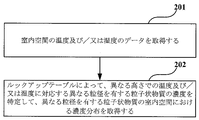
- Fig. 4 is a flow chart of a method for implementing step 101 in Embodiment 1 of the present invention
- FIG. 4 is an exemplary diagram of a lookup table in Embodiment 1 of the present invention
- FIG. 2 is a diagram showing the relationship between the number/concentration distribution of particulate matter indoors, draft, and natural wind in Example 1 of the present invention.
- FIG. 4 is a flow chart of another method for implementing step 101 in Embodiment 1 of the present invention
- FIG. 4 is a flow chart of a method for training a first neural network model in Embodiment 1 of the present invention;
- FIG. 4 is a schematic diagram of training of the first neural network in Example 1 of the present invention
- FIG. 4 is a flow chart of yet another method for implementing step 101 in Embodiment 1 of the present invention
- FIG. FIG. 2 is a schematic diagram of fitting the indoor particulate matter concentration distribution in Example 1 of the present invention.
- FIG. 4 is a flow chart of yet another method for implementing step 101 in Embodiment 1 of the present invention
- FIG. FIG. 4 is a flow chart of yet another method for implementing step 101 in Embodiment 1 of the present invention
- FIG. FIG. 4 is a schematic diagram for predicting the concentration distribution in Example 1 of the present invention
- FIG. 4 is a flow chart of yet another method for implementing step 101 in Embodiment 1 of the present invention
- FIG. 4 is a diagram of several examples of controlling the inlet and the outlet according to obstacles in Embodiment 1 of the present invention;
- Fig. 4 is a flow chart of a method for implementing step 102 in Embodiment 1 of the present invention;
- FIG. 10 is a flow chart of a control method for a purification device in Example 2 of the present invention;
- FIG. 4 is a flow chart of a method for training a prediction model in embodiment 2 of the present invention;
- FIG. 10 is a schematic diagram of input data of four CHANNELs obtained in step 1701 in Example 2 of the present invention;
- FIG. 11 is a schematic diagram of each CHANNEL passing through a long-term short-term memory (LSTM) neural network in step 1702 in Example 2 of the present invention;
- LSTM long-term short-term memory
- FIG. 5 is a schematic diagram for predicting the concentration distribution in Example 2 of the present invention
- FIG. 10 is another flow chart of the control method of the purifier in Embodiment 2 of the present invention.
- FIG. FIG. 4 is a flow chart of a method for implementing step 1603 in Embodiment 2 of the present invention;
- FIG. FIG. 4 is a flow chart of another method for implementing step 1603 in embodiment 2 of the present invention;
- FIG. FIG. 10 is still another flow chart of the control method of the purification equipment in the second embodiment of the present invention;
- FIG. It is a schematic diagram of the control apparatus of the purification apparatus in Example 3 of this invention. It is a schematic diagram of the control apparatus of the purification apparatus in Example 4 of this invention.
- FIG. 10 is a structural diagram of a purification device in Example 5 of the present invention
- FIG. 10 is a schematic diagram of a plurality of states of the first baffle plate in Example 5 of the present invention
- FIG. 10 is a schematic diagram of two states of the third baffle plate in Example 5 of the present invention
- Embodiment 1 of the present invention provides a control method for purification equipment.
- FIG. 1 is a flow chart of a control method for purification equipment according to Embodiment 1 of the present invention. As shown in FIG. 1, the method includes the following steps.
- Step 101 Identifying the concentration distribution in the indoor space of particulate matter with different particle sizes
- Step 102 Controlling at least one device parameter of the purification device according to the concentration distribution of the particulate matter with different particle sizes in the indoor space.
- the purifying device is controlled according to the concentration distribution of the particulate matter having different particle sizes in the indoor space, it is possible to perform targeted control of the particulate matter having different particle sizes, thereby improving the purifying efficiency and speed. can be enhanced, and a good purification effect can be achieved quickly and with high efficiency.
- the concentration distribution may refer to a two-dimensional distribution of the distribution of different particle sizes and the distribution of the number of each particle size.
- the purification equipment may be various types of purification equipment. Examples include air purifiers, fresh air equipment, and air conditioners with an air purification function.
- the purification equipment may be for domestic use, commercial use, or public use.
- the purification device may be used in a residential environment, in commercial environments such as offices, office buildings, and shopping malls, or in public environments such as schools.
- the method of controlling a purification device may be performed by the purification device.
- it may be performed by the controller of the purification equipment.
- step 101 the concentration distribution in the indoor space of particulate matter having different particle sizes is identified.
- particulate matter having different particle sizes may be broadly divided into, for example, particulate matter having a large particle size and particulate matter having a small particle size.
- particulate matter with different particle sizes may be separated according to a unified standard, such as particulate matter PM10 and particulate matter PM2.5.
- the concentration distribution of particulate matter in the indoor space refers to the concentration distribution of particulate matter at different spatial positions in the room, for example, the concentration distribution at different heights in the room.
- step 101 The method for implementing step 101 will be specifically described below.
- FIG. 2 is a flowchart of a method for implementing step 101 in embodiment 1 of the present invention. As shown in FIG. 2, the method comprises: Step 201: Obtaining indoor space temperature and/or humidity data; Step 202: Identify the concentrations of particulate matter with different particle sizes corresponding to temperature and/or humidity at different heights by means of a lookup table, and the concentration distribution of particulate matter with different particle sizes in the indoor space be obtained.
- indoor space temperature and/or humidity data is obtained, for example, by an indoor temperature sensor and/or humidity sensor.
- the sensor may be a plurality of sensors at different positions in the room, or may be a sensor movable in the room.
- the lookup table is a table created in advance and stored in a database.
- FIG. 3 is an exemplary diagram of a lookup table in Example 1 of the present invention. As shown in FIG. 3, as the temperature and humidity increase, the distribution position of particulate matter gradually decreases.
- step 202 by accessing the database and retrieving and matching the lookup table in the database, particulate matter having different particle sizes corresponding to the temperature and/or humidity at different heights. Determine the concentration of
- the concentration of particulate matter with diameter increases.
- FIG. 4 is a diagram showing the relationship between the number/concentration distribution of particulate matter indoors, draft, and natural wind in Example 1 of the present invention. As shown in FIG. 4, even when the temperature and humidity are constant, the distribution of particulate matter differs between the natural ventilation state and the non-ventilation state. In embodiments of the present invention, it is possible to control the purification device based on that point.
- FIG. 5 is a flowchart of another method for realizing step 101 in embodiment 1 of the present invention. As shown in FIG. 5, the method includes the following steps.
- Step 501 Obtaining indoor space temperature and/or humidity data
- Step 502 Inputting the temperature and/or humidity data and height information into a first neural network model to obtain concentration distribution of particulate matter with different particle sizes in indoor space.
- Step 501 is similar to step 201. Here, detailed description should be omitted.
- step 502 the temperature and/or humidity data and height information are input to the first neural network model to obtain the concentration distribution of particulate matter having different particle sizes in the indoor space, and the height information is, for example, the height of the room and/or the height of the floor where the purification equipment is located.
- the first neural network model is a pre-trained model.
- the training method of the first neural network model will be exemplified below.
- FIG. 6 is a flowchart of a method for training the first neural network model in Example 1 of the present invention. As shown in FIG. 6, the method includes the following steps.
- Step 601 Entering the current temperature/humidity and height parameters
- Step 602 training with the deployed fully connected neural network
- Step 603 Saving the model after the training of the model is completed.
- FIG. 7 is a schematic diagram during training of the first neural network in Example 1 of the present invention.
- the first neural network is a fully connected neural network, where the input T indicates temperature, RH indicates relative humidity, H indicates height, and P indicates Indicates the concentration of particulate matter. That is, it inputs temperature, humidity, and at least one height parameter, and outputs concentration values of particulate matter having different particle sizes predicted through an all-connected network.
- the loss function is represented by the following formula (1).
- Loss (p prediction - p truth ) 2 (1) where Loss denotes the loss value, pprediction denotes the particulate matter concentration value output from the first neural network, and ptruth denotes the true value of the particulate matter concentration.
- a corrected slope value which is the corresponding slope value, is obtained simply by obtaining the inverse derivative, and minimizing LOSS makes the corresponding slope value even more accurate. Therefore, when the model is used positively, the accuracy is even higher. After training is complete, the model may be saved.
- FIG. 8 is a flowchart of yet another method for realizing step 101 in embodiment 1 of the present invention. As shown in FIG. 8, the method includes the following steps.
- Step 801 Obtaining sensor readings for particulate matter with different particle sizes in the room;
- Step 802 Fitting the concentration distribution of particulate matter with different particle sizes in the indoor space according to the values of the sensor for particulate matter with different particle sizes in the room.
- multiple sensors are used to detect particulate matter having different particle sizes in a room, and further for example, the multiple sensors are provided at different heights in the room.
- multiple PM2.5 sensors and/or multiple PM10 sensors are provided at different heights in the room.
- a plurality of sensors to other different particle sizes such as PM0.5, PM1, PM2, PM3, PM4 and PM5 may also be included.
- FIG. 9 is a schematic diagram for fitting the indoor concentration distribution of particulate matter in Example 1 of the present invention. As shown in FIG. 9, for particulate matter with a certain particle size, the 3D distribution of the concentration of particulate matter in the room is fitted based on the concentration values of the particulate matter at multiple locations detected by the sensor. do. Similar fitting measures may also be taken for particulate matter having other particle sizes.
- step 101 has been described for identifying the current concentration distribution of particulate matter having different particle sizes in the indoor space.
- the future concentration distribution of particulate matter having different particle sizes in the indoor space may be predicted.
- FIG. 10 is a flow chart of yet another method for realizing step 101 in the first embodiment of the present invention. As shown in FIG. 10, the method includes the following steps.
- Step 1001 Obtaining indoor space temperature and/or humidity data
- Step 1002 Predicting the concentration distribution of particulate matter having different particle sizes in the indoor space at a plurality of times after the current time based on the temperature and/or humidity data of the indoor space.
- step 102 adjusts control over at least one device parameter in real time according to the concentration distribution in the indoor space of particulate matter having different particle sizes at the plurality of times.
- it may be predicted by a neural network or by a simulation model.
- the temperature and/or humidity data and height information are input to the second neural network model, and the concentration distribution of particulate matter having different particle sizes in the indoor space at a plurality of times after the current time to get
- the temperature and/or humidity data and height information are input to the simulation model to obtain the concentration distribution of particulate matter having different particle sizes in the indoor space at a plurality of times after the current time. .
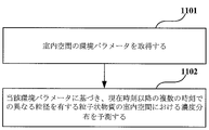
- FIG. 11 is a flow chart of yet another method for realizing step 101 in the first embodiment of the present invention. As shown in FIG. 11, the method includes the following steps.
- Step 1101 Obtaining environmental parameters of the indoor space;
- Step 1102 Predicting the concentration distribution of particulate matter having different particle sizes in the indoor space at a plurality of times after the current time based on the environmental parameters.
- an indoor house layout diagram may be obtained. Then, it is possible to predict the concentration distribution of pollutants at a plurality of times after the current time based on the environmental parameters and the house layout.
- the house layout plan may include at least one element of floor plan, furniture arrangement, orientation, and geographical position.
- the interior layout map of the house may be obtained based on the building information model and/or the interior image captured by the camera.
- the environmental parameters of the indoor space are obtained.
- the environmental parameter is at least one of temperature, humidity, concentration of particulate matter with different particle sizes, concentration of VOCs, concentration of formaldehyde, concentration of odor, and concentration of carbon dioxide.
- concentration of particulate matter with different particle sizes concentration of VOCs, concentration of formaldehyde, concentration of odor, and concentration of carbon dioxide.
- the environmental parameter may be obtained by a plurality of sensors arranged at different positions in the room or by at least one sensor movable in the room.
- the environmental parameters include at least one environmental parameter sequence of environmental parameters at a plurality of consecutive times at at least one position point in the room.
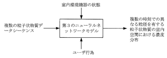
- the at least one environmental parameter sequence may be input to a third neural network model or simulation model to output the concentration distribution of pollutants at multiple times after the current time.
- the environmental parameters may include multiple environmental parameters at different heights in the room.
- the prediction accuracy can be further improved, and the purification efficiency and effect can be further improved.
- the environmental parameters include four environmental parameter sequences of environmental parameters at eight consecutive times at four location points in the room, and in step 1102, the four environmental parameter sequences as four channels.
- the four position points can almost completely cover the detection of the environmental parameters distributed throughout the room, and the four position points can divide the indoor space into four parts uniformly. Since each of the four parts has one piece of reference data, accuracy is ensured and costs are suppressed.
- the third neural network model is a deep neural network including a long short-term memory (LSTM) structure or a gated recurrence unit (GRU) structure.
- LSTM long short-term memory
- GRU gated recurrence unit
- the simulation model is a Computational Fluid Dynamics (CFD) simulation model.
- CFD Computational Fluid Dynamics
- the at least one environmental parameter sequence includes multiple particulate matter data sequences at different locations in the room.
- the third neural network model may be a trained deep neural network including a long short-term memory (LSTM) structure or a gated regression unit (GRU) structure.
- LSTM long short-term memory
- GRU gated regression unit
- indoor environment devices include, for example, air conditioners, humidifiers, cleaning robots, and fresh air devices
- user actions include, for example, smoking, opening windows, and , including actions such as cooking rice.
- FIG. 12 is a schematic diagram for predicting the concentration distribution in Example 1 of the present invention. As shown in FIG. 12, a plurality of particulate matter data sequences at different locations in the room, the state of indoor environmental equipment, and user actions are input into a third neural network model, and A concentration distribution in an indoor space of particulate matter having different particle sizes is obtained.
- the simulation model is, for example, a Computational Fluid Dynamics (CFD) simulation model.
- CFD Computational Fluid Dynamics
- the concentration distribution of particulate matter may be specified by combining the indoor layout of the house.
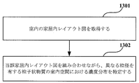
- FIG. 13 is a flow chart of yet another method for realizing step 101 in the first embodiment of the present invention. As shown in FIG. 13, the method includes the following steps.
- Step 1301 Obtaining an indoor house layout plan
- Step 1302 Identify the concentration distribution of particulate matter having different particle sizes in the indoor space while combining the indoor layout diagrams.
- the interior layout of the house may be obtained from the BIM model and/or the interior images captured by the camera.
- the house layout plan may include elements such as floor plan, furniture placement, orientation, and geographic location.
- the purification equipment in addition to controlling the purification equipment according to the concentration distribution of particulate matter in pollutants, the purification equipment may also be controlled according to the concentration distribution of other pollutants in the indoor space.
- the method may further include the following steps.
- Step 103 Determining the concentration distribution of pollutants other than particulate matter in the indoor space; and Step 104: Controlling at least one equipment parameter of the purification equipment according to the concentration distribution of the other pollutants in the indoor space.
- steps 103-104 and steps 101-103 may be executed in sequence or in parallel. Also, step 102 and step 104 may be combined and executed. That is, at least one device parameter of the purification device may be controlled according to the concentration distribution in the indoor space of particulate matter having different particle sizes and the concentration distribution of other pollutants in the indoor space.
- contaminants may include contaminants such as odors, formaldehyde, VOCs, and dust.
- the purifier can purify air comprehensively and efficiently, further improving device performance and user experience.
- step 102 or step 104 at least one device parameter of the purification device is controlled.
- the device parameters may be various parameters related to air purification processing.
- the device parameter is at least one of the opening/closing number, opening/closing range, and opening/closing angle of the suction port, or at least one of the opening/closing number, opening/closing range, and opening/closing angle of the outlet. , or the magnitude of the wind force, or the mode of operation.
- step 102 the inlet and outlet of the purifier are controlled according to the concentration distribution of particulate matter having different particle sizes in the indoor space.
- the purification efficiency and purification effect can be further improved by performing bi-directional control of the suction port and the blow-out port.
- the purification equipment may be provided with an environmental sensor for sensing obstacles in the environment.
- the method may further include the following steps.
- Step 105 Control at least one of the opening/closing number, opening/closing range, and opening/closing angle of the inlet and the outlet based on the result of detection of obstacles around the purification equipment.
- the parameters of the inlet and the outlet can be controlled in a timely manner, ensuring the purification effect and improving the energy saving performance of the equipment. can be done.
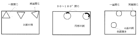
- FIG. 14A and 14B are diagrams of several examples of controlling the inlet and the outlet according to obstacles in the first embodiment of the present invention.
- the detection results for the surrounding wall surface can be used to close the inlet and outlet on one side, or open the inlet and outlet on both sides. close up.
- the cross-section of the air purifier is of circular construction, the result of detection against the surrounding wall closes the angle range of 90-180° at the inlet and outlet.
- the detection results for the surrounding wall surface can be used to close the inlet and outlet on one side, or to close the inlet and outlet on both sides, or to close the inlet and outlet. To fully open a suction port and a blowing port without closing the mouth.
- FIG. 15 is a flow chart of a method for realizing step 102 in Embodiment 1 of the present invention. As shown in FIG. 15, the method includes the following steps.
- Step 1501 controlling the opening range of the inlet and the outlet according to the concentration distribution of particulate matter with different particle sizes in the indoor space;
- Step 1502 After the purification device has been running for an hour, changing the opening range of the inlet and the outlet according to the results of detecting or predicting particulate matter with different particle sizes.
- the opening range of the inlet and the outlet is changed from the detection result or the prediction result. And the control over the air outlet can always ensure the optimization of purification efficiency and purification effect, further improving the performance of the equipment.
- the opening range of the suction port and the blowout port is controlled within the low-altitude region, and the wind force is increased to After the purifier has been in operation for one hour, the upper opening range of the inlet and the outlet is gradually increased according to the results of detection or prediction of particulate matter.
- the opening range of the inlet and outlet can be controlled in the low altitude region and the wind force can be controlled.
- the opening range of the suction port and the air outlet is gradually increased from the bottom to the top based on the result of detection or prediction. Then, high purification efficiency and good purification effect can be obtained.
- the opening range of the suction port and the blow-out port is controlled to the maximum range above the altitude, and the operation of the purifier is controlled. After continuing for a period of time, the upper opening range of the inlet and outlet is gradually reduced according to the results of detection or prediction of particulate matter.
- the opening range of the inlet and the outlet is controlled to the maximum range on the altitude, and the indoor operation is for one hour.
- the upper opening range of the suction port and the blowing port is gradually reduced, and the cleaning of the particulate matter is performed in order, so that a high cleaning efficiency and a good cleaning effect can be obtained.
- the method comprises: The step of activating a noise reduction module may also be included if the noise of the purification device is greater than a preset threshold.
- the noise reduction module when activated, it broadcasts music or sounds that encourage sleep or rest, such as white noise.
- the atmosphere can be softened by broadcasting music or sound, improving the user experience.
- the embodiment of the present invention further provides a control method for purification equipment, the control method including the following steps.
- Step S1 Acquiring current humidity/temperature data
- Step S2 The storage module looks up according to a look-up table of the content of particulate matter with different particle sizes at temperatures and humidity corresponding to different heights
- Step S3 Determining the current state of distribution of particulate matter from the results of the lookup table
- Step S4 according to the current distribution of particulate matter, output the area and number of the corresponding inlets and outlets, and the control range of the wind force
- Step S5 Controlling the operating state of the purifying equipment according to the area and number of the inlet and the outlet and the control range of the wind force
- Step S6 After the internal circulation operation continues for one hour at the bottom of the indoor space, the area of the outlet is gradually increased according to the distribution state of the particulate matter at different times when the simulation is performed, outputting a control command to reduce
- Step S7 Control so that the area of the outlet of the purifier is gradually increased or decreased by sequentially increasing or decreasing the area of the outlet.
- particulate matter having different particle sizes can be used. It is possible to perform objective control on the air, improve the purification efficiency and speed, and realize a good purification effect quickly and with high efficiency.
- the purification equipment In addition, it predicts the concentration distribution of pollutants at multiple times after the current time based on the collected current environmental parameters, and controls the purification equipment according to the predicted concentration distribution of pollutants. It is possible to acquire the concentration distribution status of future contaminants without having to carry out The processing speed is fast, and the energy saving performance of the equipment is improved. Further, by controlling the purifying equipment according to the future concentration distribution, the purifying efficiency is increased and the effect is improved. Therefore, it is possible to perform the air purification treatment with high efficiency, speed, and energy saving.
- Embodiment 2 of the present invention provides a control method for purification equipment.
- FIG. 16 is a flow chart of a control method for purification equipment according to Embodiment 2 of the present invention. As shown in FIG. 16, the method includes the following steps.
- Step 1601 Obtaining environmental parameters of the indoor space; Step 1602: Predicting the concentration distribution of the contaminant at multiple times after the current time based on the environmental parameter; and Step 1603: Controlling at least one equipment parameter of the purification equipment according to the concentration distribution of the contaminant at a plurality of times after the current time.
- the concentration distribution of contaminants at multiple times after the current time is predicted, and the purification equipment is controlled according to the predicted concentration distribution of contaminants, so detection is constantly performed. It is possible to acquire the concentration distribution status of future contaminants without having to carry out The processing speed is fast, and the energy saving performance of the equipment is improved. Further, by controlling the purifying equipment according to the future concentration distribution, the purifying efficiency is increased and the effect is improved. Therefore, it is possible to perform the air purification treatment with high efficiency, speed, and energy saving.
- the purification equipment may be various types of purification equipment. Examples include air purifiers, fresh air equipment, and air conditioners with an air purification function.
- the purification equipment may be for domestic use, commercial use, or public use.
- the purification device may be used in a residential environment, in commercial environments such as offices, office buildings, and shopping malls, or in public environments such as schools.
- the purification equipment control method may be performed by the purification equipment.
- it may be performed by the controller of the purification equipment.
- an indoor house layout diagram may be acquired. Then, it is possible to predict the concentration distribution of pollutants at a plurality of times after the current time based on the environmental parameters and the house layout.
- the house layout plan may include at least one element of floor plan, furniture arrangement, orientation, and geographical position.
- the interior layout map of the house may be obtained based on the building information model and/or the interior image captured by the camera.
- step 1601 environmental parameters of the indoor space are obtained.
- the environmental parameter is at least one of temperature, humidity, concentration of particulate matter with different particle sizes, concentration of VOCs, concentration of formaldehyde, concentration of odor, and concentration of carbon dioxide.
- concentration of particulate matter with different particle sizes concentration of VOCs, concentration of formaldehyde, concentration of odor, and concentration of carbon dioxide.
- the concentration distribution of the pollutants includes the concentration distribution of particulate matter having different particle sizes in the indoor space, the concentration distribution of VOC in the indoor space, the concentration distribution of formaldehyde in the indoor space, and the concentration distribution of odor. At least one of a concentration distribution in the indoor space and a concentration distribution of carbon dioxide in the indoor space is included.
- the environmental parameter may be obtained by a plurality of sensors arranged at different positions in the room or by at least one sensor movable in the room.
- the environmental parameters include at least one environmental parameter sequence of environmental parameters at a plurality of consecutive times at at least one position point in the room.
- the at least one environmental parameter sequence may be input into the simulation model, and the concentration distribution of pollutants at multiple times after the current time may be output.
- the environmental parameters may include multiple environmental parameters at different heights in the room.
- the prediction accuracy can be further improved, and the purification efficiency and effect can be further improved.
- the environmental parameters include four environmental parameter sequences of environmental parameters at eight consecutive times at four location points in the room, and step 102 converts the four environmental parameter sequences into four channels of the Input to the simulation model and output the concentration distribution of pollutants at multiple times after the current time.
- the four position points can almost completely cover the detection of the environmental parameters distributed throughout the room, and the four position points can divide the indoor space into four parts uniformly. Since each of the four parts has one piece of reference data, accuracy is ensured and costs are suppressed.
- the prediction model may be a deep neural network model or a simulation model.
- the simulation model is a deep neural network that includes a long-term short-term memory (LSTM) structure or a gated recurrence unit (GRU) structure.
- LSTM long-term short-term memory
- GRU gated recurrence unit
- the simulation model is a Computational Fluid Dynamics (CFD) simulation model.
- CFD Computational Fluid Dynamics
- the following is an exemplary explanation of the training process of a deep neural network as a prediction model.
- FIG. 17 is a flow chart of a method for training a prediction model in Example 2 of the present invention. As shown in FIG. 17, the method includes the following steps.
- Step 1701 Obtain the corresponding 4 CHANNEL inputs at 4 location points, each CHANNEL input being environmental parameter data at 8 consecutive time points;
- Step 1702 Each CHANNEL is passed through a long short-term memory (LSTM) neural network or a gated regression unit (GRU) neural network to calculate the value of one extracted feature;
- Step 1703 Superimposing each CHANNEL obtained in step 202 unit by unit, and after superimposing, obtaining the output of four units with future information, ie the temporal feature layer.
- LSTM long short-term memory
- GRU gated regression unit
- the output as a temporal feature layer may be used to identify control commands for future purification equipment.
- FIG. 18 is a schematic diagram of input data for four CHANNELs obtained in step 1701 in Example 2 of the present invention.
- FIG. 19 is a schematic diagram of each CHANNEL passing through a long-term short-term memory (LSTM) neural network in step 1702 in embodiment 2 of the present invention.
- LSTM long-term short-term memory
- one CHANNEL input is particulate matter data with different particle sizes at eight consecutive time points.
- the eight consecutive time points are one hour apart, but other time intervals may be used. Embodiments of the present invention are not so limited.
- the prediction model becomes more and more optimized through iterations, the accuracy of the predicted contaminant concentration distribution becomes higher, and the corresponding control commands become more precise. becomes.
- the trained prediction model By saving the trained prediction model and using it directly in the subsequent steps, it is possible to directly obtain the accurate concentration distribution of pollutants at multiple times in the future. For example, by determining the size of the inlet and outlet in advance according to the concentration distribution of contaminants at multiple times in the future, it is possible to improve the purification efficiency and detect the concentration distribution of contaminants. Energy-saving performance is also improved by adjusting and controlling according to the actual situation until it can be thoroughly cleaned without having to repeat it.
- prediction can also be made by combining indoor environment equipment and user behavior.
- step 1602 the at least one environmental parameter sequence, the state of the indoor environmental equipment, and/or the user's behavior are input into the predictive model, and the concentration distribution of pollutants at multiple times after the current time is output.
- indoor environment devices include, for example, air conditioners, humidifiers, cleaning robots, and fresh air devices
- user actions include, for example, smoking, opening windows, and , including actions such as cooking rice.
- FIG. 20 is a schematic diagram for predicting the concentration distribution in Example 2 of the present invention. As shown in FIG. 20, at least one environmental parameter sequence, the state of indoor environmental equipment, and user behavior are input into the predictive model to obtain the concentration distribution of pollutants at multiple times after the current time.
- the device parameters may be various parameters related to air purification processing.
- the device parameter is at least one of the opening/closing number, opening/closing range, and opening/closing angle of the suction port, or at least one of the opening/closing number, opening/closing range, and opening/closing angle of the outlet. , or the magnitude of the wind force, or the mode of operation.
- step 1602 the inlet and outlet of the purification equipment are controlled according to the predicted concentration distribution of pollutants.
- the number of pollutants at a plurality of times after the current time is specified, and the purification equipment is controlled based on the number of pollutants.
- FIG. 21 is another flow chart of the control method of the purification equipment according to the second embodiment of the present invention. As shown in FIG. 21, the control method includes the following steps.
- Step 2101 Obtaining environmental parameters of the indoor space; Step 2102: Predicting the concentration distribution of the contaminant at multiple times after the current time based on the environmental parameter; and Step 2103: Determining the number of contaminants at multiple times after the current time according to the concentration distribution of the pollutants at multiple times after the current time; Step 2104: Controlling at least one equipment parameter of the purification equipment based on the number of contaminants at multiple times since the current time.
- the number of pollutants identified according to the concentration distribution of pollutants can be accurate and reflect the distribution characteristics.
- purification efficiency and effectiveness are further enhanced.
- the number of particulate matter with different particle sizes is calculated, and based on that number, the accuracy and number of lifting and lowering of the suction port are further improved. can be controlled.
- particulate matter having a large particle size is present at the bottom of the entire indoor space, increasing the number and height of the suction ports accelerates the suction of the particulate matter, thereby achieving rapid purification.
- the number of contaminants is obtained by multiplying the concentration of the contaminants by the volume.
- the number of pollutants may be actually detected, a lookup table may be created, and the future number of pollutants may be obtained by a table reference method according to the predicted concentration distribution of pollutants.
- the purification equipment may be provided with an environmental sensor for sensing obstacles in the environment.
- the method may further include the following steps.
- Step 1604 Control at least one of the opening/closing number, opening/closing range, and opening/closing angle of the suction port and the outlet from the result of detection of obstacles around the purification equipment.
- the parameters of the inlet and the outlet can be controlled in a timely manner, ensuring the purification effect and improving the energy saving performance of the equipment. can be done.
- the cross section of the air purifier has a three-sided structure as shown in FIG. Close the inlet and outlet on both sides. If the cross-section of the air purifier is of circular construction, the result of detection against the surrounding wall closes the angle range of 90-180° at the inlet and outlet. If the cross section of the air purifier has a four-sided structure, the detection results for the surrounding wall surface can be used to close the inlet and outlet on one side, or to close the inlet and outlet on both sides, or to close the inlet and outlet. To fully open a suction port and a blowing port without closing the mouth.
- the device parameters may be various parameters related to air purification processing.
- the device parameter is at least one of the opening/closing number, opening/closing range, and opening/closing angle of the suction port, or at least one of the opening/closing number, opening/closing range, and opening/closing angle of the outlet. , or the magnitude of the wind force, or the mode of operation.
- step 1603 if it is identified that the pollutant tends to increase or decrease according to the concentration distribution of the pollutant at a plurality of times after the current time, the number of openings and closings of the inlet and outlet, The opening/closing range or the opening/closing angle is controlled to increase or decrease accordingly.
- step 2104 based on the number of contaminants at a plurality of times after the current time, if it is identified that the contaminants tend to increase or decrease, the number of openings and closings of the inlet and outlet;
- the opening/closing range or the opening/closing angle is controlled to increase or decrease accordingly.
- the area, number, and wind control range of the inlet and outlet of the purification equipment will be adjusted accordingly. can optimize the cleaning effect. Further energy savings can be achieved by avoiding re-detection and reinstallation.
- step 1603 may identify at least one control strategy and the time required for implementation of the control strategy by the purification device.
- the time required for the multiple control measures may differ.
- multiple control strategies correspond to different inlet and outlet sizes and different air volumes.
- one control strategy may be selected, the control strategy with the shortest required time may be automatically selected, or it may be selected by the user.
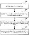
- FIG. 22 is a flowchart of a method for realizing step 1603 in embodiment 2 of the present invention. As shown in FIG. 22, the method includes the following steps.
- Step 2201 Identifying at least one control strategy and the time required for implementation of the control strategy by the purification device as a function of the concentration distribution of the contaminant at multiple times after the current time;
- STEP 2202 Identifying and providing at least one control strategy to a user;
- Step 2203 Controlling the purification equipment according to the control strategy selected by the user.
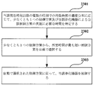
- FIG. 23 is a flowchart of another method for realizing step 1603 in embodiment 2 of the present invention. As shown in FIG. 23, the method includes the following steps.
- Step 2301 Identifying at least one control strategy and the time required for implementation of the control strategy by the purification device as a function of the concentration distribution of the contaminant at multiple times after the current time;
- Step 2302 Automatically selecting the control strategy with the shortest duration from the at least one control strategy;
- Step 2303 Control the purification equipment according to the automatically selected control strategy.
- the method comprises: The step of activating a noise reduction module may also be included if the noise of the purification device is greater than a preset threshold.
- the noise reduction module when activated, it broadcasts music or sounds that encourage sleep or rest.
- FIG. 24 is another flow chart of the control method of the purification equipment in the second embodiment of the present invention. As shown in FIG. 24, the control method includes the following steps.
- Step 2401 Obtaining historical data of contaminant concentration distribution
- Step 2402 Input historical data of pollutant concentration distribution into a predictive model based on LSTM units, and output the concentration distribution of pollutants at different times in the future
- Step 2403 calculating the number of contaminants at different times in the future
- Step 2404 outputting a control command to sequentially increase or decrease the area of the outlet
- Step 2405 Control so that the area of the outlet is gradually increased or decreased according to the control command.
- the concentration distribution of pollutants at multiple times after the current time is predicted based on the collected current environmental parameters, and the purification equipment is controlled according to the predicted concentration distribution of pollutants. Therefore, the future concentration distribution of contaminants can be obtained without continuous detection.
- the processing speed is fast, and the energy saving performance of the equipment is improved.
- the purifying efficiency is increased and the effect is improved. Therefore, it is possible to perform the air purification treatment with high efficiency, speed, and energy saving.
- Embodiment 3 of the present invention provides a purification equipment control apparatus corresponding to the purification equipment control method described in Embodiment 1, and for specific implementation thereof, refer to the implementation of the method described in Embodiment 1. omit the description for the same or related content.
- FIG. 25 is a schematic diagram of a control device for purification equipment according to a third embodiment of the present invention.
- the purification equipment control device 2500 a specifying unit 2501 for specifying the concentration distribution in the indoor space of particulate matter having different particle sizes; and a first control unit 2502 for controlling at least one device parameter of the purification device according to the concentration distribution in the indoor space of particulate matter having different particle sizes.
- Embodiment 1 the contents of the related steps in Embodiment 1 may be referred to for realizing the functions of the above means. Please omit the explanation here.
- the purification device control device 2500 may be provided in the purification device or may be an independent device.
- the purification equipment control device 2500 may also include other control functions, such as power switch correctness and timing control.
- the purifier is controlled according to the concentration distribution of the particulate matter having different particle sizes in the indoor space, the particulate matter having different particle sizes can be objectively controlled. , the purification efficiency and speed can be increased, and a good purification effect can be achieved quickly and efficiently.
- Embodiment 4 of the present invention provides a purification equipment control apparatus corresponding to the purification equipment control method described in Embodiment 2, and for specific implementation thereof, refer to the implementation of the method described in Embodiment 2. omit the description for the same or related content.
- FIG. 26 is a schematic diagram of a control device for purification equipment according to Embodiment 4 of the present invention.
- the purification equipment control device 2600 includes: an acquisition unit 2601 for acquiring environmental parameters of the indoor space; a prediction unit 2602 for predicting the contaminant concentration distribution at multiple times after the current time based on the environmental parameter; a second control unit 2603 for controlling at least one equipment parameter of the purification equipment according to the contaminant concentration distribution at a plurality of times after the current time.
- Embodiment 1 the contents of the related steps in Embodiment 1 may be referred to for realizing the functions of the above means. Please omit the explanation here.
- the purification device control device 2600 may be provided in the purification device or may be an independent device.
- the purification equipment control device 2600 may also include other control functions, such as control of power switch correctness and timing, for example.
- the concentration distribution of pollutants at multiple times after the current time is predicted based on the collected current environmental parameters, and the purification equipment is controlled according to the predicted concentration distribution of pollutants. Therefore, the future concentration distribution of contaminants can be obtained without continuous detection.
- the processing speed is fast, and the energy saving performance of the equipment is improved.
- the purifying efficiency is increased and the effect is improved. Therefore, it is possible to perform the air purification treatment with high efficiency, speed, and energy saving.
- Example 5 of the present invention provides a purification equipment comprising the control device for the purification equipment according to Example 3 or 4, and the specific implementation thereof is the device according to Example 3 or 4. Or you may refer to the implementation of the method described in Example 1 or Example 2, and omit the description for the same or related content.
- control device of the purification equipment described in Example 3 or Embodiment 4 is a controller provided in the purification equipment, or the control device is integrated in the controller of the purification equipment. ing.
- FIG. 27 is a structural diagram of a purification device in Example 5 of the present invention.
- purification device 2700 includes: a controller (not shown in FIG. 27); an outer case 2710 provided with suction ports 2711 and 2712 at the lower end and bottom of the peripheral side edge; further comprising an interior case 2720 provided with outlets 2721 and 2722 on the peripheral side edge and the upper side,
- the interior case 2710 is fitted in the exterior case 2720 and is vertically adjusted by vertical adjustment means (not shown in FIG. 27), a filter body means 2730 provided in the interior case 2720;
- a blower (not shown in FIG.
- a first baffle plate is provided at the inlet
- a second baffle plate is provided at the outlet
- the control device controls at least one of the suction port, the discharge port, the vertical adjustment means, the first baffle plate, and the second baffle plate in accordance with the control command.
- a suction port 2723 is further provided at the bottom of the interior case 2720 .
- the first baffle plate is provided in the inner case 2720, the first baffle plate is provided at the peripheral side edge of the inner case and perpendicular to the upper side edge of the inner case. , the first baffle plates are distributed in a rotational manner.
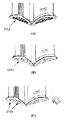
- FIG. 28 is a schematic diagram of a plurality of states of the first baffle plate in Example 5 of the present invention.
- FIG. 28A when the suction port 2711 is closed, the first baffle plate 2713 is closed.
- FIG. 28B when an obstacle is detected around the purification equipment, the first baffle plates 2713 on the four surfaces rotate in the same direction. open.
- FIG. 28C when there is an obstacle around part of the suction port 2711, the first baffle plate 2713 corresponding to the position of the obstacle is closed and the remaining first air guide plate 2713 is closed. 2713 are rotationally opened in the same direction.
- the suction effect is improved and the air is drawn in in a rotating manner.
- the efficiency of the fan is increased by sucking air according to the direction of rotation of the fan. It is also possible for the air in the indoor space to become dynamically rotating.
- the first baffle plate on each surface may be controlled individually.
- the second baffle plate includes a baffle door, the size of the baffle door is the same as the outlet, and the baffle door is controlled by the control device according to the control command. , the opening area of the outlet may be controlled.
- the outlet 2722 on the upper side of the interior case 2720 may be provided with a third baffle plate that can be raised and lowered.
- FIG. 29 is a schematic diagram of two states of the third baffle plate in Example 5 of the present invention. As shown in FIGS. 29A and 29B, by adjusting the elevation of the third baffle plate 2724, the angle and opening area of the third baffle plate can be changed, and the blowing efficiency can be improved. And the purification efficiency can be increased.
- filter body means 2730 includes a first filter screen, a second filter screen and a third filter screen;
- the first filter screen, the second filter screen, and the third filter screen are provided in parallel, and the second filter screen is provided between the inlet and the outlet of the interior case 2720.
- the first filter screen is provided in the inner case 2720 .
- the first filter screen may be provided inside the exterior case 2710 .
- FIG. 27 schematically shows each filter screen, but the position within the purification device 2700 is not shown.
- the suction port at the bottom of the peripheral side edge of the inner case first sucks in a large amount of particulate matter having a small particle size from the upper suction port, and keeps it for an hour. After continuation, it will move to the lower air intake to suck the particulate matter with large particle size, and cooperate with the bottom air intake to achieve a better purification effect.
- the second filter screen and the third filter screen are then not tightly connected and the active space is formed so that there is a gap between the filter screens and the purification space is optimized.
- the suction port and the discharge port may be provided with a lighting lamp, and the length of the lighting lamp matches the length of the corresponding suction port and the discharge port.
- the movement of the particulate matter can be clearly seen by irradiation with the lamp, and the comparison between the particulate matter at the inlet and the particulate matter at the outlet can be visualized, and a better purification effect can be obtained. be done.
- it may be used as an illumination lamp at night.
- the color and length of the lights can be changed, and the music played in the entertainment mode provides a good effect in terms of user experience.
- the purification device 2700 may be for domestic use, commercial use, or public use.
- the purification device 2700 may be used in residential environments, commercial environments such as offices, office buildings, and shopping malls, or public environments such as schools.
- the purifier is controlled according to the concentration distribution of the particulate matter having different particle sizes in the indoor space, the particulate matter having different particle sizes can be objectively controlled. , the purification efficiency and speed can be increased, and a good purification effect can be achieved quickly and efficiently.
- the above devices and methods in the embodiments of the present invention may be realized by hardware, or by a combination of hardware and software.
- the present invention relates to a computer-readable program as follows.
- the logic unit can implement the above devices or components, or can implement the above various methods or steps.
- Embodiments of the present invention relate to storage media for storing the above programs, such as hard disks, magnetic disks, optical disks, DVDs, flash memories, and the like.
Landscapes
- Engineering & Computer Science (AREA)
- Signal Processing (AREA)
- Chemical & Material Sciences (AREA)
- Combustion & Propulsion (AREA)
- Mechanical Engineering (AREA)
- General Engineering & Computer Science (AREA)
- Physics & Mathematics (AREA)
- Fuzzy Systems (AREA)
- Mathematical Physics (AREA)
- Air Conditioning Control Device (AREA)
Abstract
Description
本発明の実施例1は、浄化機器の制御方法を提供する。図1は、本発明の実施例1における浄化機器の制御方法のフローチャートである。図1に示されるように、当該方法では、以下のステップが含まれる。
ステップ102:当該異なる粒径を有する粒子状物質の室内空間における濃度分布に応じて、当該浄化機器の少なくとも1つの機器パラメータを制御すること。
ステップ101では、異なる粒径を有する粒子状物質の室内空間における濃度分布を特定する。
ステップ201:室内空間の温度及び/又は湿度のデータを取得すること、および、
ステップ202:ルックアップテーブルによって、異なる高さでの温度及び/又は湿度に対応する異なる粒径を有する粒子状物質の濃度を特定して、異なる粒径を有する粒子状物質の室内空間における濃度分布を取得すること。
ステップ502:当該温度及び/又は湿度のデータ及び高さ情報を第1のニューラルネットワークモデルに入力して、異なる粒径を有する粒子状物質の室内空間における濃度分布を取得すること。
ステップ602:配置された全接続ニューラルネットワークを用いてトレーニングすること、及び、
ステップ603:モデルのトレーニングが完了した後、当該モデルを保存すること。
ここで、Lossが損失値を示し、p予測が第1のニューラルネットワークから出力された粒子状物質の濃度値を示し、p真実が粒子状物質の濃度の真の値を示す。
ステップ802:室内における異なる粒径を有する粒子状物質に対する当該センサの数値に基づいて、異なる粒径を有する粒子状物質の室内空間における濃度分布をフィッティングすること。
ステップ1002:当該室内空間の温度及び/又は湿度のデータに基づき、現在時刻以降の複数の時刻での異なる粒径を有する粒子状物質の室内空間における濃度分布を予測すること。
ステップ1102:当該環境パラメータに基づき、現在時刻以降の複数の時刻での異なる粒径を有する粒子状物質の室内空間における濃度分布を予測すること。
ステップ1302:当該家屋内レイアウト図を組み合わせながら、異なる粒径を有する粒子状物質の室内空間における濃度分布を特定すること。
ステップ104:室内空間における当該他の汚染物質の濃度分布に応じて、当該浄化機器の少なくとも1つの機器パラメータを制御すること。
ステップ1502:当該浄化機器の運転が一時間帯にわたって継続した後、異なる粒径を有する粒子状物質に対する検出の結果又は予測の結果から、当該吸込み口と当該吹出し口の開放範囲を変化させること。
当該浄化機器のノイズが予め設定された閾値よりも大きい場合、ノイズ除去モジュールを起動させるステップがさらに含まれてもよい。
ステップS2:記憶モジュールは、異なる高さに対応する温度・湿度での異なる粒径を有する粒子状物質の含有量のルックアップテーブルに基づいて調べること、
ステップS3:ルックアップテーブルによる調べの結果から、現在 の粒子状物質の分布状態を判断すること、
ステップS4:現在の粒子状物質の分布状態に応じて、対応する吸込み口と吹出し口の面積、数、風力の制御範囲を出力すること、
ステップS5:吸込み口と吹出し口の面積、数、風力の制御範囲に応じて、浄化機器の運転状態を制御すること、
ステップS6:室内空間における底部に内部循環運転が一時間帯にわたって継続した後、シミュレーションが行われた異なる時刻での粒子状物質の分布状態に応じて、吹出し口の面積を順次に大きくしたり、小さくしたりする制御指令を出力すること、および、
ステップS7:吹出し口の面積を順次に大きくしたり小さくしたりすることで、浄化機器の吹出し口の面積が順次に大きくなったり、小さくなったりするように制御すること。
本発明の実施例2は、浄化機器の制御方法を提供する。図16は、本発明の実施例2における浄化機器の制御方法のフローチャートである。図16に示されるように、当該方法では、以下のステップが含まれる。
ステップ1602:当該環境パラメータに基づいて現在時刻以降の複数の時刻での汚染物質の濃度分布を予測すること、および、
ステップ1603:当該現在時刻以降の複数の時刻での汚染物質の濃度分布に応じて、浄化機器の少なくとも1つの機器パラメータを制御すること。
ステップ1702:各CHANNELは、それぞれ、長期短期記憶(LSTM)ニューラルネットワーク又はゲート付き回帰ユニット(GRU)ニューラルネットワークを通過して、1つの抽出される特徴の値を算出すること、および、
ステップ1703:ステップ202で得られた各CHANNELをユニットごとに重畳し、重畳後、将来の情報が付けられた4つのユニットの出力、すなわち、時間特徴層が得られること。
ステップ2102:当該環境パラメータに基づいて現在時刻以降の複数の時刻での汚染物質の濃度分布を予測すること、および、
ステップ2103:当該現在時刻以降の複数の時刻での汚染物質の濃度分布に応じて、当該現在時刻以降の複数の時刻での汚染物質の数を特定すること、および、
ステップ2104:当該現在時刻以降の複数の時刻での汚染物質の数に基づいて、浄化機器の少なくとも1つの機器パラメータを制御すること。
ステップ2202:少なくとも1つの制御方策を特定してユーザに提供すること、および、
ステップ2203:ユーザによって選択された制御方策に従って、当該浄化機器を制御すること。
ステップ2302:少なくとも1つの制御方策から、所要時間が最も短い制御方策を自動で選択すること、および、
ステップ2303:自動で選択された制御方策に従って、当該浄化機器を制御すること。
本発明の実施例では、当該方法では、
当該浄化機器のノイズが予め設定された閾値よりも大きい場合、ノイズ除去モジュールを起動させるステップがさらに含まれてもよい。
ステップ2402:汚染物質の濃度分布の履歴データを、LSTMユニットに基づく予測モデルに入力し、将来の異なる時刻での汚染源の濃度分布を出力すること、
ステップ2403:将来の異なる時刻での汚染物質の数を計算すること、
ステップ2404:吹出し口の面積を順次に大きくしたり小さくしたりする制御指令を出力すること、および、
ステップ2405:当該制御指令に応じて、吹出し口の面積が順次に大きくなったり小さくなったりように制御すること。
本発明の実施例3は、実施例1に記載の浄化機器の制御方法に対応する浄化機器の制御装置を提供し、その具体的な実施について、実施例1に記載の方法の実施を参照されてもよく、同一又は関連する内容に対し、説明を省略されたい。
異なる粒径を有する粒子状物質の室内空間における濃度分布を特定するための特定ユニット2501と、
当該異なる粒径を有する粒子状物質の室内空間における濃度分布に応じて、浄化機器の少なくとも1つの機器パラメータを制御するための第1の制御ユニット2502と、を備えた。
本発明の実施例4は、実施例2に記載の浄化機器の制御方法に対応する浄化機器の制御装置を提供し、その具体的な実施について、実施例2に記載の方法の実施を参照されてもよく、同一又は関連する内容に対し、説明を省略されたい。
室内空間の環境パラメータを取得するための取得ユニット2601と、
当該環境パラメータに基づいて現在時刻以降の複数の時刻での汚染物質の濃度分布を予測するための予測ユニット2602と、
当該現在時刻以降の複数の時刻での汚染物質の濃度分布に応じて、浄化機器の少なくとも1つの機器パラメータを制御するための第2の制御ユニット2603と、を備えた。
本発明の実施例5は、実施例3または実施例4に記載の浄化機器の制御装置を備えた浄化機器を提供し、その具体的な実施について、実施例3または実施例4に記載の装置又は実施例1または実施例2に記載の方法の実施を参照されてもよく、同一又は関連する内容に対し、説明を省略されたい。
制御装置(図27に示されないもの)と、
周側縁における下端部と底部には吸込み口2711と2712が設けられた外装ケース2710と、
周側縁と上側には吹出し口2721と2722が設けられた内装ケース2720と、をさらに備え、
当該内装ケース2710は、外装ケース2720内に嵌め込まれるとともに、上下調節手段(図27に示されないもの)によって昇降調節され、
当該内装ケース2720内に設けられたフィルタ本体手段2730と、
内装ケース又は外装ケース内に設けられた送風機(図27に示されないもの)と、をさらに備え、
吸込み口には第1の導風板が設けられ、吹出し口には第2の導風板が設けられ、
当該制御装置は、制御指令に応じて、吸込み口、吹出し口、上下調節手段、第1の導風板、および、第2の導風板のうちの少なくとも1つを制御する。
第1のフィルタスクリーン、第2のフィルタスクリーン、および、第3のフィルタスクリーンは平行に設けられており、第2のフィルタスクリーンは、内装ケース2720における吸込み口と吹出し口の間に設けられており、第1のフィルタスクリーンは、内装ケース2720内に設けられている。
Claims (53)
- 異なる粒径を有する粒子状物質の室内空間における濃度分布を特定するステップ、及び、
前記異なる粒径を有する粒子状物質の室内空間における濃度分布に応じて、浄化機器の少なくとも1つの機器パラメータを制御するステップ、
を含む、ことを特徴とする、
浄化機器の制御方法。 - 異なる粒径を有する粒子状物質の室内空間における濃度分布を特定する前記ステップは、
室内空間の温度及び/又は湿度のデータを取得するステップ、および、
ルックアップテーブルによって、異なる高さでの温度及び/又は湿度に対応する異なる粒径を有する粒子状物質の濃度を特定して、異なる粒径を有する粒子状物質の室内空間における濃度分布を取得するステップ、
を含む、ことを特徴とする、
請求項1に記載の制御方法。 - 異なる粒径を有する粒子状物質の室内空間における濃度分布を特定する前記ステップは、
室内空間の温度及び/又は湿度のデータを取得するステップ、および、
前記温度及び/又は湿度のデータ及び高さ情報を第1のニューラルネットワークモデルに入力して、異なる粒径を有する粒子状物質の室内空間における濃度分布を取得するステップ、
を含む、ことを特徴とする、
請求項1に記載の制御方法。 - 異なる粒径を有する粒子状物質の室内空間における濃度分布を特定する前記ステップは、
室内における異なる粒径を有する粒子状物質に対するセンサの数値を取得するステップ、および、
室内における異なる粒径を有する粒子状物質に対する前記センサの数値に基づいて、異なる粒径を有する粒子状物質の室内空間における濃度分布をフィッティングするステップ、
を含む、ことを特徴とする、
請求項1に記載の制御方法。 - 異なる粒径を有する粒子状物質の室内空間における濃度分布を特定する前記ステップは、
室内空間の温度及び/又は湿度のデータを取得するステップ、および、
前記室内空間の温度及び/又は湿度のデータに基づき、現在時刻以降の複数の時刻での異なる粒径を有する粒子状物質の室内空間における濃度分布を予測するステップ、
を含む、ことを特徴とする、
請求項1に記載の制御方法。 - 前記室内空間の温度及び/又は湿度のデータに基づき、現在時刻以降の複数の時刻での異なる粒径を有する粒子状物質の室内空間における濃度分布を予測する前記ステップは、
前記温度及び/又は湿度のデータ及び高さ情報を第2のニューラルネットワークモデルに入力して、現在時刻以降の複数の時刻での、異なる粒径を有する粒子状物質の室内空間における濃度分布を取得するステップ、を含む、ことを特徴とする、
請求項5に記載の制御方法。 - 前記室内空間の温度及び/又は湿度のデータに基づき、現在時刻以降の複数の時刻での異なる粒径を有する粒子状物質の室内空間における濃度分布を予測する前記ステップは、
前記温度及び/又は湿度のデータ及び高さ情報をシミュレーションモデルに入力して、現在時刻以降の複数の時刻での、異なる粒径を有する粒子状物質の室内空間における濃度分布を取得するステップ、を含む、ことを特徴とする、
請求項5に記載の制御方法。 - 前記異なる粒径を有する粒子状物質の室内空間における濃度分布に応じて、前記浄化機器の少なくとも1つの機器パラメータを制御する前記ステップは、
前記複数の時刻での、異なる粒径を有する粒子状物質の室内空間における濃度分布に応じて、少なくとも1つの機器パラメータに対する制御指令をリアルタイムに調整するステップ、を含む、ことを特徴とする、
請求項5に記載の制御方法。 - 異なる粒径を有する粒子状物質の室内空間における濃度分布を特定する前記ステップは、
室内の家屋内レイアウト図を取得するステップ、及び、
前記家屋内レイアウト図を組み合わせながら、異なる粒径を有する粒子状物質の室内空間における濃度分布を特定するステップ、
を含む、ことを特徴とする、
請求項1に記載の制御方法。 - 粒子状物質以外の他の汚染物質の室内空間における濃度分布を特定するステップ、及び、
前記他の汚染物質の室内空間における濃度分布に応じて、当該浄化機器の少なくとも1つの機器パラメータを制御するステップ、
をさらに含む、ことを特徴とする、
請求項1に記載の制御方法。 - 前記異なる粒径を有する粒子状物質の室内空間における濃度分布に応じて、前記浄化機器の少なくとも1つの機器パラメータを制御する前記ステップは、
前記異なる粒径を有する粒子状物質の室内空間における濃度分布に応じて、前記浄化機器の吸込み口と吹出し口を制御するステップ、を含む、ことを特徴とする、
請求項1に記載の制御方法。 - 前記浄化機器の周囲にある障害物に対する検出の結果から、吸込み口と吹出し口の開閉数、開閉範囲、および、開閉角度、のうちの少なくとも1つを制御するステップ、
をさらに含む、ことを特徴とする、
請求項1に記載の制御方法。 - 前記異なる粒径を有する粒子状物質の室内空間における濃度分布に応じて、前記浄化機器の少なくとも1つの機器パラメータを制御する前記ステップは、
異なる粒径を有する粒子状物質の室内空間における濃度分布に応じて、吸込み口と吹出し口の開放範囲を制御するステップ、および、
前記浄化機器の運転が一時間帯にわたって継続した後、異なる粒径を有する粒子状物質に対する検出の結果又は予測の結果から、前記吸込み口と前記吹出し口の開放範囲を変化させるステップ、
を含む、ことを特徴とする、
請求項1に記載の制御方法。 - 大粒径を有する粒子状物質の室内における高度が低い領域での濃度が大きいとき、吸込み口と吹出し口の開放範囲を、高度が低い領域内に制御するとともに、風力を大きくし、
前記浄化機器の運転が一時間帯にわたって継続した後、粒子状物質に対する検出の結果又は予測の結果から、吸込み口と吹出し口の高度上の開放範囲を徐々に大きくする、
ことを特徴とする、
請求項13に記載の制御方法。 - 大粒径を有する粒子状物質の室内における高度が低い領域での濃度が小さいとき、吸込み口と吹出し口の開放範囲を、高度上の最大範囲に開放するように制御し、
前記浄化機器の運転が一時間帯にわたって継続した後、粒子状物質に対する検出の結果又は予測の結果から、吸込み口と吹出し口の高度上の開放範囲を徐々に小さくする、
ことを特徴とする、
請求項13に記載の制御方法。 - 異なる粒径を有する粒子状物質の室内空間における濃度分布を特定する前記ステップは、
室内空間の環境パラメータを取得するステップ、および、
前記環境パラメータに基づき、現在時刻以降の複数の時刻での異なる粒径を有する粒子状物質の室内空間における濃度分布を予測するステップ、
を含む、ことを特徴とする、
請求項1に記載の制御方法。 - 室内の家屋内レイアウト図を取得するステップ、
をさらに含み、
前記環境パラメータに基づき、現在時刻以降の複数の時刻での異なる粒径を有する粒子状物質の室内空間における濃度分布を予測する前記ステップは、
前記環境パラメータと前記家屋内レイアウト図に基づき、現在時刻以降の複数の時刻での異なる粒径を有する粒子状物質の室内空間における濃度分布を予測するステップ、を含む、ことを特徴とする、
請求項16に記載の制御方法。 - 前記家屋内レイアウト図は、間取り、家具の配置、向き、および、地理的位置、のうちの少なくとも1つの要素を含み、
前記家屋内レイアウト図は、建物情報モデル及び/又はカメラによって撮影された室内画像に基づいて得られる、
ことを特徴とする、
請求項17に記載の制御方法。 - 前記環境パラメータは、室内における少なくとも1つの位置点での、連続した複数の時刻での環境パラメータの少なくとも1つの環境パラメータシーケンスを含み、
前記環境パラメータに基づき、現在時刻以降の複数の時刻での異なる粒径を有する粒子状物質の室内空間における濃度分布を予測する前記ステップは、
前記少なくとも1つの環境パラメータシーケンスを第3のニューラルネットワークモデル又はシミュレーションモデルに入力し、現在時刻以降の複数の時刻での異なる粒径を有する粒子状物質の室内空間における濃度分布を出力するステップ、を含む、ことを特徴とする、
請求項16に記載の制御方法。 - 前記環境パラメータは、室内における4つの位置点での、連続した8つの時刻での環境パラメータの4つの環境パラメータシーケンスを含み、
前記環境パラメータに基づき、現在時刻以降の複数の時刻での異なる粒径を有する粒子状物質の室内空間における濃度分布を予測する前記ステップは、
前記4つの環境パラメータシーケンスを4つのチャネルとして前記第3のニューラルネットワークモデル又は前記シミュレーションモデルに入力し、現在時刻以降の複数の時刻での異なる粒径を有する粒子状物質の室内空間における濃度分布を出力するステップ、を含む、ことを特徴とする、
請求項19に記載の制御方法。 - 前記環境パラメータは、室内における異なる位置に配置された複数のセンサ又は室内を移動可能な少なくとも1つのセンサによって得られる、ことを特徴とする、
請求項16に記載の制御方法。 - 前記環境パラメータは、室内における異なる高さでの複数の環境パラメータを含む、ことを特徴とする、
請求項16に記載の制御方法。 - 異なる粒径を有する粒子状物質の室内空間における濃度分布を特定する前記ステップは、
前記少なくとも1つの環境パラメータシーケンス、室内環境機器の状態及び/又はユーザ行為を前記第3のニューラルネットワークモデル又は前記シミュレーションモデルに入力し、現在時刻以降の複数の時刻での異なる粒径を有する粒子状物質の室内空間における濃度分布を取得するステップ、を含む、ことを特徴とする、
請求項19に記載の制御方法。 - 前記少なくとも1つの環境パラメータシーケンスは、室内における異なる位置での複数の粒子状物質データシーケンスを含む、ことを特徴とする、
請求項23に記載の制御方法。 - 前記環境パラメータは、温度、湿度、異なる粒径を有する粒子状物質の濃度、VOC濃度、ホルムアルデヒドの濃度、臭気濃度、および、二酸化炭素濃度、のうちの少なくとも1つを含む、ことを特徴とする、
請求項16に記載の制御方法。 - 室内空間の環境パラメータを取得するステップ、
前記環境パラメータに基づいて現在時刻以降の複数の時刻での汚染物質の濃度分布を予測するステップ、および、
前記現在時刻以降の複数の時刻での汚染物質の濃度分布に応じて、浄化機器の少なくとも1つの機器パラメータを制御するステップ、
を含む、ことを特徴とする、
浄化機器の制御方法。 - 室内の家屋内レイアウト図を取得するステップ、
をさらに含み、
前記環境パラメータに基づいて現在時刻以降の複数の時刻での汚染物質の濃度分布を予測する前記ステップは、
前記環境パラメータと前記家屋内レイアウト図とに基づいて現在時刻以降の複数の時刻での汚染物質の濃度分布を予測するステップ、を含む、ことを特徴とする、
請求項26に記載の制御方法。 - 前記家屋内レイアウト図は、間取り、家具の配置、向き、および、地理的位置、のうちの少なくとも1つの要素を含み、
前記家屋内レイアウト図は、建物情報モデル及び/又はカメラによって撮影された室内画像に基づいて得られる、
ことを特徴とする、
請求項27に記載の制御方法。 - 前記環境パラメータは、室内における少なくとも1つの位置点での、連続した複数の時刻での環境パラメータの少なくとも1つの環境パラメータシーケンスを含み、
前記環境パラメータに基づいて現在時刻以降の複数の時刻での汚染物質の濃度分布を予測する前記ステップは、
前記少なくとも1つの環境パラメータシーケンスを予測モデルに入力し、現在時刻以降の複数の時刻での汚染物質の濃度分布を出力するステップ、を含む、ことを特徴とする、
請求項26に記載の制御方法。 - 前記環境パラメータは、室内における4つの位置点での、連続した8つの時刻での環境パラメータの4つの環境パラメータシーケンスを含み、
前記環境パラメータに基づいて現在時刻以降の複数の時刻での汚染物質の濃度分布を予測する前記ステップは、
前記4つの環境パラメータシーケンスを4つのチャネルとして前記予測モデルに入力し、現在時刻以降の複数の時刻での汚染物質の濃度分布を出力するステップ、を含む、ことを特徴とする、
請求項29に記載の制御方法。 - 前記環境パラメータは、室内における異なる位置に配置された複数のセンサ又は室内を移動可能な少なくとも1つのセンサによって得られる、ことを特徴とする、
請求項26に記載の制御方法。 - 前記環境パラメータは、室内における異なる高さでの複数の環境パラメータを含む、ことを特徴とする、
請求項26に記載の制御方法。 - 前記環境パラメータに基づいて現在時刻以降の複数の時刻での汚染物質の濃度分布を予測する前記ステップは、
前記少なくとも1つの環境パラメータシーケンス、室内環境機器の状態及び/又はユーザ行為を予測モデルに入力し、現在時刻以降の複数の時刻での汚染物質の濃度分布を出力するステップ、を含む、ことを特徴とする、
請求項29に記載の制御方法。 - 前記予測モデルは、深層ニューラルネットワークモデル又はシミュレーションモデルである、ことを特徴とする、
請求項29に記載の制御方法。 - 前記現在時刻以降の複数の時刻での汚染物質の濃度分布に応じて、前記現在時刻以降の複数の時刻での汚染物質の数を特定するステップ、
をさらに含み、
前記現在時刻以降の複数の時刻での汚染物質の濃度分布に応じて、浄化機器の少なくとも1つの機器パラメータを制御する前記ステップは、
前記現在時刻以降の複数の時刻での汚染物質の数に基づいて、浄化機器の少なくとも1つの機器パラメータを制御するステップ、を含む、ことを特徴とする、
請求項26に記載の制御方法。 - 前記汚染物質の濃度分布に応じて、浄化機器の少なくとも1つの機器パラメータを制御する前記ステップは、
前記汚染物質の濃度分布に応じて、浄化機器の吸込み口と吹出し口を制御するステップ、を含む、ことを特徴とする、
請求項26に記載の制御方法。 - 前記浄化機器の周囲にある障害物に対する検出の結果から、吸込み口と吹出し口の開閉数、開閉範囲、および、開閉角度、のうちの少なくとも1つを制御するステップ、
をさらに含む、ことを特徴とする、
請求項26に記載の制御方法。 - 前記現在時刻以降の複数の時刻での汚染物質の濃度分布に応じて、浄化機器の少なくとも1つの機器パラメータを制御する前記ステップは、
前記現在時刻以降の複数の時刻での汚染物質の濃度分布に応じて、汚染物質が増加又は減少する傾向があることを特定した場合、吸込み口と吹出し口の開閉数、開閉範囲、又は、開閉角度、が相応に増大又は減少するように制御するステップ、を含む、ことを特徴とする、
請求項26に記載の制御方法。 - 前記現在時刻以降の複数の時刻での汚染物質の数に応じて、浄化機器の少なくとも1つの機器パラメータを制御する前記ステップは、
前記現在時刻以降の複数の時刻での汚染物質の数に基づいて、汚染物質が増加又は減少する傾向があることを特定した場合、吸込み口と吹出し口の開閉数、開閉範囲、又は、開閉角度、が相応に増大又は減少するように制御するステップ、を含む、ことを特徴とする、
請求項35に記載の制御方法。 - 前記現在時刻以降の複数の時刻での汚染物質の濃度分布に応じて、浄化機器の少なくとも1つの機器パラメータを制御する前記ステップは、
前記現在時刻以降の複数の時刻での汚染物質の濃度分布に応じて、少なくとも1つの制御方策及び前記浄化機器による前記制御方策の実施に必要な時間を特定するステップ、を含む、ことを特徴とする、
請求項26に記載の制御方法。 - 前記現在時刻以降の複数の時刻での汚染物質の濃度分布に応じて、浄化機器の少なくとも1つの機器パラメータを制御する前記ステップは、
少なくとも1つの制御方策を特定してユーザに提供するステップ、および、
ユーザによって選択された制御方策に従って、前記浄化機器を制御するステップ、
をさらに含む、ことを特徴とする、
請求項40に記載の制御方法。 - 前記現在時刻以降の複数の時刻での汚染物質の濃度分布に応じて、浄化機器の少なくとも1つの機器パラメータを制御する前記ステップは、
少なくとも1つの制御方策から、所要時間が最も短い制御方策を自動で選択するステップ、および、
自動で選択された制御方策に従って、前記浄化機器を制御するステップ、
をさらに含む、ことを特徴とする、
請求項40に記載の制御方法。 - 前記環境パラメータは、温度、湿度、異なる粒径を有する粒子状物質の濃度、VOC濃度、ホルムアルデヒドの濃度、臭気濃度、および、二酸化炭素濃度、のうちの少なくとも1つを含む、ことを特徴とする、
請求項26から42のいずれか1項に記載の制御方法。 - 前記浄化機器のノイズが予め設定された閾値よりも大きい場合、ノイズ除去モジュールを起動させるステップ、
をさらに含む、ことを特徴とする、
請求項1または26に記載の制御方法。 - 前記機器パラメータは、
吸込み口の開閉数、開閉範囲、および、開閉角度のうちの少なくとも1つであり、又は、
吹出し口の開閉数、開閉範囲、および、開閉角度のうちの少なくとも1つであり、又は、
風力の大きさであり、又は、
運転モードである、
ことを特徴とする、
請求項1から42のいずれか1項に記載の制御方法。 - 異なる粒径を有する粒子状物質の室内空間における濃度分布を特定するための特定ユニットと、
前記異なる粒径を有する粒子状物質の室内空間における濃度分布に応じて、浄化機器の少なくとも1つの機器パラメータを制御するための第1の制御ユニットと、
を備える、ことを特徴とする、
浄化機器の制御装置。 - 室内空間の環境パラメータを取得するための取得ユニットと、
前記環境パラメータに基づいて現在時刻以降の複数の時刻での汚染物質の濃度分布を予測するための予測ユニットと、
前記現在時刻以降の複数の時刻での汚染物質の濃度分布に応じて、浄化機器の少なくとも1つの機器パラメータを制御するための第2の制御ユニットと、
を備える、ことを特徴とする、
浄化機器の制御装置。 - 請求項46または47に記載の浄化機器の制御装置、
を備える、ことを特徴とする、
浄化機器。 - 周側縁における下端部と底部には吸込み口が設けられた外装ケースと、
周側縁と上側には吹出し口が設けられた内装ケースと、
をさらに備え、
前記内装ケースは、外装ケース内に嵌め込まれるとともに、上下調節手段によって昇降調節され、
前記浄化機器は、
前記内装ケース内に設けられたフィルタ本体手段と、
内装ケース又は外装ケース内に設けられた送風機と、
をさらに備え、
前記吸込み口には第1の導風板が設けられ、
前記吹出し口には第2の導風板が設けられ、
前記制御装置は、制御指令に応じて、前記吸込み口、前記吹出し口、前記上下調節手段、前記第1の導風板、および、前記第2の導風板、のうちの少なくとも1つを制御する、
ことを特徴とする、
請求項48に記載の浄化機器。 - 前記第1の導風板は、内装ケース内に設けられ、
前記第1の導風板は、前記内装ケースの周側縁に設けられるとともに、前記内装ケースの上側縁と直交し、
前記第1の導風板は、回転状に分布している、
ことを特徴とする、
請求項49に記載の浄化機器。 - 前記第2の導風板は、導風扉を含み、
前記導風扉の大きさは、前記吹出し口と一致し、
前記導風扉は、前記制御装置による制御指令に応じて、前記吹出し口の開口面積を制御する、
ことを特徴とする、
請求項49に記載の浄化機器。 - 前記フィルタ本体手段は、第1のフィルタスクリーン、第2のフィルタスクリーン、および、第3のフィルタスクリーン、を含み、
前記第1のフィルタスクリーン、前記第2のフィルタスクリーン、および、前記第3のフィルタスクリーン、は平行に設けられており、
前記第2のフィルタスクリーンは、前記内装ケースにおける吸込み口と吹出し口の間に設けられており、
前記第1のフィルタスクリーンは、前記外装ケース又は前記内装ケース内に設けられている、
ことを特徴とする、
請求項50に記載の浄化機器。 - 前記第2のフィルタスクリーンと前記第3のフィルタスクリーンの間には、予め設定された空間を有する、ことを特徴とする、
請求項52に記載の浄化機器。
Priority Applications (3)
| Application Number | Priority Date | Filing Date | Title |
|---|---|---|---|
| JP2023530418A JP7695583B2 (ja) | 2021-06-17 | 2022-06-16 | 浄化機器の制御方法及び装置、浄化機器 |
| EP22825073.4A EP4357691A4 (en) | 2021-06-17 | 2022-06-16 | CONTROL METHOD AND DEVICE FOR CLEANING EQUIPMENT AND CLEANING EQUIPMENT |
| US18/538,181 US20240175596A1 (en) | 2021-06-17 | 2023-12-13 | Control method and device for purification equipment, and purification equipment |
Applications Claiming Priority (4)
| Application Number | Priority Date | Filing Date | Title |
|---|---|---|---|
| CN202110671095.XA CN115493227B (zh) | 2021-06-17 | 2021-06-17 | 净化设备的控制方法及装置、净化设备 |
| CN202110671442.9A CN115493228B (zh) | 2021-06-17 | 2021-06-17 | 净化设备的控制方法及装置、净化设备 |
| CN202110671095.X | 2021-06-17 | ||
| CN202110671442.9 | 2021-06-17 |
Related Child Applications (1)
| Application Number | Title | Priority Date | Filing Date |
|---|---|---|---|
| US18/538,181 Continuation US20240175596A1 (en) | 2021-06-17 | 2023-12-13 | Control method and device for purification equipment, and purification equipment |
Publications (1)
| Publication Number | Publication Date |
|---|---|
| WO2022265085A1 true WO2022265085A1 (ja) | 2022-12-22 |
Family
ID=84527556
Family Applications (1)
| Application Number | Title | Priority Date | Filing Date |
|---|---|---|---|
| PCT/JP2022/024223 Ceased WO2022265085A1 (ja) | 2021-06-17 | 2022-06-16 | 浄化機器の制御方法及び装置、浄化機器 |
Country Status (4)
| Country | Link |
|---|---|
| US (1) | US20240175596A1 (ja) |
| EP (1) | EP4357691A4 (ja) |
| JP (1) | JP7695583B2 (ja) |
| WO (1) | WO2022265085A1 (ja) |
Cited By (2)
| Publication number | Priority date | Publication date | Assignee | Title |
|---|---|---|---|---|
| CN117933479A (zh) * | 2024-01-29 | 2024-04-26 | 山东耘威医疗科技有限公司 | 一种室内洁净环境信息的智能化管理方法及系统 |
| CN118640561A (zh) * | 2024-08-15 | 2024-09-13 | 江苏众兴永达制冷机械制造有限公司 | 用于粉尘过滤的工业空调净化控制方法及系统 |
Families Citing this family (1)
| Publication number | Priority date | Publication date | Assignee | Title |
|---|---|---|---|---|
| CN119755788A (zh) * | 2025-03-06 | 2025-04-04 | 深圳市富临厨房设备有限公司 | 一种基于空气净化的智能控制系统及方法 |
Citations (11)
| Publication number | Priority date | Publication date | Assignee | Title |
|---|---|---|---|---|
| JP2000205615A (ja) * | 1999-01-11 | 2000-07-28 | Kawai Musical Instr Mfg Co Ltd | 空気清浄器 |
| JP2001099462A (ja) * | 1999-09-28 | 2001-04-13 | Matsushita Electric Ind Co Ltd | クリーンルームまたはクリーンブース内の特定領域環境の最適制御解析値表示システム |
| JP2009095768A (ja) * | 2007-10-17 | 2009-05-07 | Panasonic Corp | 空気清浄機 |
| CN103604192A (zh) | 2013-11-18 | 2014-02-26 | 宁波哲恺电器有限公司 | 一种空气净化器的节能控制方法 |
| WO2015063867A1 (ja) * | 2013-10-29 | 2015-05-07 | 三菱電機株式会社 | 空気清浄機 |
| CN104913454A (zh) | 2015-06-05 | 2015-09-16 | 广东美的制冷设备有限公司 | 用于空气净化装置的控制系统、控制方法及家用电器 |
| CN105659033A (zh) | 2013-10-22 | 2016-06-08 | 三菱电机株式会社 | 空气净化器 |
| CN106907791A (zh) | 2015-12-22 | 2017-06-30 | 松下知识产权经营株式会社 | 空气净化器 |
| JP2020085547A (ja) * | 2018-11-19 | 2020-06-04 | 株式会社日建設計総合研究所 | データ計測システム及び建物設備制御システム |
| CN111814956A (zh) * | 2020-06-23 | 2020-10-23 | 哈尔滨工程大学 | 一种基于多维度二次特征提取的多任务学习的空气质量预测方法 |
| JP2020182638A (ja) * | 2019-05-07 | 2020-11-12 | 株式会社竹中工務店 | 環境改善装置 |
Family Cites Families (1)
| Publication number | Priority date | Publication date | Assignee | Title |
|---|---|---|---|---|
| CN108120661B (zh) * | 2017-12-19 | 2021-02-05 | 北京理工大学 | 一种城市空气中颗粒物含量时空分布测定方法 |
-
2022
- 2022-06-16 JP JP2023530418A patent/JP7695583B2/ja active Active
- 2022-06-16 WO PCT/JP2022/024223 patent/WO2022265085A1/ja not_active Ceased
- 2022-06-16 EP EP22825073.4A patent/EP4357691A4/en active Pending
-
2023
- 2023-12-13 US US18/538,181 patent/US20240175596A1/en active Pending
Patent Citations (11)
| Publication number | Priority date | Publication date | Assignee | Title |
|---|---|---|---|---|
| JP2000205615A (ja) * | 1999-01-11 | 2000-07-28 | Kawai Musical Instr Mfg Co Ltd | 空気清浄器 |
| JP2001099462A (ja) * | 1999-09-28 | 2001-04-13 | Matsushita Electric Ind Co Ltd | クリーンルームまたはクリーンブース内の特定領域環境の最適制御解析値表示システム |
| JP2009095768A (ja) * | 2007-10-17 | 2009-05-07 | Panasonic Corp | 空気清浄機 |
| CN105659033A (zh) | 2013-10-22 | 2016-06-08 | 三菱电机株式会社 | 空气净化器 |
| WO2015063867A1 (ja) * | 2013-10-29 | 2015-05-07 | 三菱電機株式会社 | 空気清浄機 |
| CN103604192A (zh) | 2013-11-18 | 2014-02-26 | 宁波哲恺电器有限公司 | 一种空气净化器的节能控制方法 |
| CN104913454A (zh) | 2015-06-05 | 2015-09-16 | 广东美的制冷设备有限公司 | 用于空气净化装置的控制系统、控制方法及家用电器 |
| CN106907791A (zh) | 2015-12-22 | 2017-06-30 | 松下知识产权经营株式会社 | 空气净化器 |
| JP2020085547A (ja) * | 2018-11-19 | 2020-06-04 | 株式会社日建設計総合研究所 | データ計測システム及び建物設備制御システム |
| JP2020182638A (ja) * | 2019-05-07 | 2020-11-12 | 株式会社竹中工務店 | 環境改善装置 |
| CN111814956A (zh) * | 2020-06-23 | 2020-10-23 | 哈尔滨工程大学 | 一种基于多维度二次特征提取的多任务学习的空气质量预测方法 |
Non-Patent Citations (1)
| Title |
|---|
| See also references of EP4357691A4 |
Cited By (2)
| Publication number | Priority date | Publication date | Assignee | Title |
|---|---|---|---|---|
| CN117933479A (zh) * | 2024-01-29 | 2024-04-26 | 山东耘威医疗科技有限公司 | 一种室内洁净环境信息的智能化管理方法及系统 |
| CN118640561A (zh) * | 2024-08-15 | 2024-09-13 | 江苏众兴永达制冷机械制造有限公司 | 用于粉尘过滤的工业空调净化控制方法及系统 |
Also Published As
| Publication number | Publication date |
|---|---|
| EP4357691A1 (en) | 2024-04-24 |
| US20240175596A1 (en) | 2024-05-30 |
| JPWO2022265085A1 (ja) | 2022-12-22 |
| EP4357691A4 (en) | 2025-01-15 |
| JP7695583B2 (ja) | 2025-06-19 |
Similar Documents
| Publication | Publication Date | Title |
|---|---|---|
| WO2022265085A1 (ja) | 浄化機器の制御方法及び装置、浄化機器 | |
| CN115493227B (zh) | 净化设备的控制方法及装置、净化设备 | |
| JP6733734B2 (ja) | 換気システム | |
| KR101808116B1 (ko) | 공기청정 시스템 | |
| JP7742550B2 (ja) | 空気質制御システム、空気質制御方法、及び、プログラム | |
| US20170350611A1 (en) | Arrangement and method for air management of a room | |
| CN205279278U (zh) | 智能净化柜式新风换气机 | |
| CN202561901U (zh) | 室内空气净化系统 | |
| CN105202646A (zh) | 智能净化柜式新风换气机 | |
| US20220325910A1 (en) | System and Method for Indoor Air Quality Purification | |
| KR101808120B1 (ko) | 실별 제어가 가능한 공기청정 시스템 | |
| CN114963461A (zh) | 用于控制智能家电联动净化的方法及装置、智能家电 | |
| CN114484836A (zh) | 全热交换器 | |
| CN118729452A (zh) | 空气流场优化的led光催化空气净化方法及装置 | |
| CN106918113A (zh) | 一种智能家居的管理方法和系统 | |
| KR20250155497A (ko) | 공기 조화 장치 및 이를 이용한 실내 압력 제어 방법 | |
| CN111520839B (zh) | 一种窗式新风净化器 | |
| CN204534877U (zh) | 一种智能洁净新风装置 | |
| CN115493228B (zh) | 净化设备的控制方法及装置、净化设备 | |
| CN108548265A (zh) | 一种虚拟管道新风设备 | |
| KR20190068869A (ko) | 공기질에 따른 가변형 환기 장치 | |
| KR102302864B1 (ko) | 공기청정 환기시스템 | |
| KR20210123082A (ko) | 환기 시스템 | |
| KR20250093822A (ko) | 인공 지능을 이용한 산소공급시스템 | |
| CN110864405A (zh) | 一种联动新风调节的家电系统 |
Legal Events
| Date | Code | Title | Description |
|---|---|---|---|
| 121 | Ep: the epo has been informed by wipo that ep was designated in this application |
Ref document number: 22825073 Country of ref document: EP Kind code of ref document: A1 |
|
| WWE | Wipo information: entry into national phase |
Ref document number: 2023530418 Country of ref document: JP |
|
| WWE | Wipo information: entry into national phase |
Ref document number: 2022825073 Country of ref document: EP |
|
| NENP | Non-entry into the national phase |
Ref country code: DE |
|
| ENP | Entry into the national phase |
Ref document number: 2022825073 Country of ref document: EP Effective date: 20240117 |