WO2022268028A1 - 车窗及汽车 - Google Patents
车窗及汽车 Download PDFInfo
- Publication number
- WO2022268028A1 WO2022268028A1 PCT/CN2022/099847 CN2022099847W WO2022268028A1 WO 2022268028 A1 WO2022268028 A1 WO 2022268028A1 CN 2022099847 W CN2022099847 W CN 2022099847W WO 2022268028 A1 WO2022268028 A1 WO 2022268028A1
- Authority
- WO
- WIPO (PCT)
- Prior art keywords
- plate
- light
- vehicle window
- equal
- protection
- Prior art date
- Legal status (The legal status is an assumption and is not a legal conclusion. Google has not performed a legal analysis and makes no representation as to the accuracy of the status listed.)
- Ceased
Links
Images


Classifications
-
- B—PERFORMING OPERATIONS; TRANSPORTING
- B60—VEHICLES IN GENERAL
- B60J—WINDOWS, WINDSCREENS, NON-FIXED ROOFS, DOORS, OR SIMILAR DEVICES FOR VEHICLES; REMOVABLE EXTERNAL PROTECTIVE COVERINGS SPECIALLY ADAPTED FOR VEHICLES
- B60J1/00—Windows; Windscreens; Accessories therefor
- B60J1/008—Windows; Windscreens; Accessories therefor of special shape, e.g. beveled edges, holes for attachment, bent windows, peculiar curvatures such as when being integrally formed with roof, door, etc.
-
- B—PERFORMING OPERATIONS; TRANSPORTING
- B62—LAND VEHICLES FOR TRAVELLING OTHERWISE THAN ON RAILS
- B62D—MOTOR VEHICLES; TRAILERS
- B62D25/00—Superstructure or monocoque structure sub-units; Parts or details thereof not otherwise provided for
- B62D25/06—Fixed roofs
-
- B—PERFORMING OPERATIONS; TRANSPORTING
- B60—VEHICLES IN GENERAL
- B60J—WINDOWS, WINDSCREENS, NON-FIXED ROOFS, DOORS, OR SIMILAR DEVICES FOR VEHICLES; REMOVABLE EXTERNAL PROTECTIVE COVERINGS SPECIALLY ADAPTED FOR VEHICLES
- B60J7/00—Non-fixed roofs; Roofs with movable panels, e.g. rotary sunroofs
-
- B—PERFORMING OPERATIONS; TRANSPORTING
- B60—VEHICLES IN GENERAL
- B60J—WINDOWS, WINDSCREENS, NON-FIXED ROOFS, DOORS, OR SIMILAR DEVICES FOR VEHICLES; REMOVABLE EXTERNAL PROTECTIVE COVERINGS SPECIALLY ADAPTED FOR VEHICLES
- B60J1/00—Windows; Windscreens; Accessories therefor
- B60J1/001—Double glazing for vehicles
-
- B—PERFORMING OPERATIONS; TRANSPORTING
- B60—VEHICLES IN GENERAL
- B60J—WINDOWS, WINDSCREENS, NON-FIXED ROOFS, DOORS, OR SIMILAR DEVICES FOR VEHICLES; REMOVABLE EXTERNAL PROTECTIVE COVERINGS SPECIALLY ADAPTED FOR VEHICLES
- B60J1/00—Windows; Windscreens; Accessories therefor
- B60J1/004—Mounting of windows
- B60J1/006—Mounting of windows characterised by fixation means such as clips, adhesive, etc.
-
- B—PERFORMING OPERATIONS; TRANSPORTING
- B62—LAND VEHICLES FOR TRAVELLING OTHERWISE THAN ON RAILS
- B62D—MOTOR VEHICLES; TRAILERS
- B62D29/00—Superstructures, understructures, or sub-units thereof, characterised by the material thereof
- B62D29/04—Superstructures, understructures, or sub-units thereof, characterised by the material thereof predominantly of synthetic material
-
- H—ELECTRICITY
- H01—ELECTRIC ELEMENTS
- H01Q—ANTENNAS, i.e. RADIO AERIALS
- H01Q1/00—Details of, or arrangements associated with, antennas
- H01Q1/12—Supports; Mounting means
- H01Q1/1271—Supports; Mounting means for mounting on windscreens
-
- H—ELECTRICITY
- H01—ELECTRIC ELEMENTS
- H01Q—ANTENNAS, i.e. RADIO AERIALS
- H01Q1/00—Details of, or arrangements associated with, antennas
- H01Q1/27—Adaptation for use in or on movable bodies
- H01Q1/32—Adaptation for use in or on road or rail vehicles
-
- H—ELECTRICITY
- H01—ELECTRIC ELEMENTS
- H01Q—ANTENNAS, i.e. RADIO AERIALS
- H01Q1/00—Details of, or arrangements associated with, antennas
- H01Q1/27—Adaptation for use in or on movable bodies
- H01Q1/32—Adaptation for use in or on road or rail vehicles
- H01Q1/325—Adaptation for use in or on road or rail vehicles characterised by the location of the antenna on the vehicle
- H01Q1/3275—Adaptation for use in or on road or rail vehicles characterised by the location of the antenna on the vehicle mounted on a horizontal surface of the vehicle, e.g. on roof, hood, trunk
-
- B—PERFORMING OPERATIONS; TRANSPORTING
- B60—VEHICLES IN GENERAL
- B60R—VEHICLES, VEHICLE FITTINGS, OR VEHICLE PARTS, NOT OTHERWISE PROVIDED FOR
- B60R11/00—Arrangements for holding or mounting articles, not otherwise provided for
- B60R11/02—Arrangements for holding or mounting articles, not otherwise provided for for radio sets, television sets, telephones, or the like; Arrangement of controls thereof
Definitions
- the present application relates to the technical field of automobiles, in particular to a vehicle window and an automobile.
- the car sunroof is installed on the roof, which can effectively circulate the air in the car and facilitate the entry of fresh air. At the same time, the car sunroof can broaden the field of vision and meet the shooting needs of mobile photography.
- Common car sunroofs include manual sunroofs, sliding sunroofs, built-in sunroofs, panoramic sunroofs, and multi-functional sunroofs.
- car sunroofs are becoming more and more popular in low-end models, and the integration of accessories is getting higher and higher.
- the car antenna usually has a hole on the outer bracket of the car body, and then transmits the signal to the device in the car.
- the manufacturing process of the outer frame of the vehicle body is complicated, and the appearance color difference between the outer frame of the vehicle body and the glass of the sunroof is relatively large, so it is impossible to realize the appearance of an all-glass car sunroof.
- the present application provides a vehicle window and an automobile that can reduce manufacturing difficulty and realize the appearance effect of a panoramic sunroof.
- the present application provides a method for molding a vehicle window, comprising:
- the second plate is spaced apart from the first light-transmitting plate to form a gap; the second plate has a mounting hole, and the mounting hole is used to accommodate a vehicle-mounted antenna; and
- An injection molding connecting piece is arranged in the gap, and the injection molding connecting piece is fixedly connected between the first transparent plate and the second plate.
- the first light-transmitting plate includes a first surface and a second surface opposite to each other, and the second plate includes a third surface and a fourth surface opposite to each other;
- the injection molding connector It includes an integrally formed first connection part, a second connection part and a third connection part, the first connection part is arranged in the gap, the second connection part is fixedly connected to the second surface, and the third connection part It is fixedly connected with the fourth surface.
- the peripheral side wall of the first light-transmitting plate is surrounded to form a receiving groove, the receiving groove is used to accommodate the second plate, and the inner wall of the receiving groove is spaced apart from the second plate
- the gap is formed, the first connecting part is arranged in the gap; the first opening of the storage tank is located on the first surface, the second opening of the storage tank is located on the second surface, and the storage tank
- the third opening of the groove is located on the peripheral side wall of the first light-transmitting plate.
- extension length of the first connecting portion along the direction from the first transparent plate to the second plate is greater than or equal to 1mm; the second connecting portion extends along the direction from the first transparent plate to the second plate The extension length in the direction of the second plate is greater than or equal to 2mm; the extension length of the third connecting portion in the direction from the first transparent plate to the second plate is greater than or equal to 2mm.
- the extending thickness of the second connecting portion along the direction perpendicular to the first transparent plate is greater than or equal to 2 mm; the extending thickness of the third connecting portion along the direction perpendicular to the second plate is greater than or equal to Equal to 2mm.
- an extension thickness of the first light-transmitting plate in a direction perpendicular to the first light-transmitting plate is less than or equal to 5 mm.
- the first light-transmitting plate is laminated glass, and the laminated glass includes at least two layers of light-transmitting glass and at least one intermediate film, and at least one intermediate film is provided between every adjacent two layers of light-transmitting glass. membrane.
- the extension thickness of the second board in a direction perpendicular to the second board is less than or equal to 5 mm.
- the second plate is single-layer glass.
- the vehicle window further includes a protective sleeve, and the protective sleeve is fixedly passed through the installation hole.
- the protection sleeve includes a first protection part, a second protection part and a third protection part integrally formed; the second protection part and the third protection part are respectively provided on the first protection part The two opposite ends; the second protection part is fixed on the third surface, and the third protection part is fixed on the fourth surface.
- the extension thickness of the first protection part along the axial direction perpendicular to the installation hole is greater than or equal to 1 mm
- the extension thickness of the second protection part along the radial direction of the installation hole is greater than or equal to 1 mm
- the thickness of the third protection portion along the axial direction of the installation hole extends greater than or equal to 1 mm.
- the present application also provides a car, including the window; the car also includes a vehicle antenna, a body bracket and an adhesive, and the adhesive is bonded to the window and the body Between the brackets; the vehicle antenna runs through the vehicle window, and is used to intercept high-frequency radio waves and transmit them to the vehicle receiver to demodulate the carrier wave.
- this application connects the first light-transmitting panel and the second panel into a whole through injection molding, and its structure is simpler, more convenient to manufacture, and lower in cost . Since both the first light-transmitting plate and the second plate are light-transmitting, the car window can achieve a panoramic effect, and the user experience is better. Since the first light-transmitting plate is not suitable for opening a mounting hole for a vehicle-mounted antenna, the application opens a mounting hole for a vehicle-mounted antenna on the second plate to reduce the impact on the appearance of the first light-transmitting plate while allowing the vehicle window to be installed with a vehicle-mounted antenna It is more convenient to realize the structural optimization of the vehicle antenna position.
- Fig. 1 is a schematic diagram of a car provided by the embodiment of the present application.
- Fig. 2 is a sectional view of a vehicle window provided in the first embodiment of the present application
- Fig. 3 is a schematic diagram of a vehicle window provided by an embodiment of the present application.
- Fig. 4 is a schematic diagram of a first light-transmitting plate provided by an embodiment of the present application.
- Fig. 5 is an assembly diagram of a first light-transmitting plate and a second plate provided in the first embodiment of the present application;
- Fig. 6 is a schematic diagram of a second plate provided by the embodiment of the present application.
- Fig. 7 is a cross-sectional view of an injection molding connector provided in the first embodiment of the present application.
- Fig. 8 is an assembly diagram of a second plate and a protective sleeve provided in the first embodiment of the present application;
- Fig. 9 is a cross-sectional view of a protective sleeve provided in the first embodiment of the present application.
- Fig. 10 is a sectional view of a vehicle window provided in the second embodiment of the present application.
- Fig. 11 is an assembly diagram of a first light-transmitting plate and a second plate provided in the second embodiment of the present application;
- Fig. 12 is a sectional view of a vehicle window provided in the third embodiment of the present application.
- Fig. 13 is an assembly diagram of a second plate and a protective sleeve provided in the third embodiment of the present application;
- Fig. 14 is a cross-sectional view of a vehicle window provided by the fourth embodiment of the present application.
- automobile 500 comprises vehicle window 100, bonding member 200, vehicle body support 300 and vehicle-mounted antenna 400, and bonding member 200 is bonded between vehicle window 100 and vehicle body support 300, thereby makes vehicle window 100 and vehicle body support 300 fixed connections to achieve the effect of the car's 500 panoramic sunroof.
- the vehicle antenna 400 penetrates and is fixed on the vehicle window 100 for intercepting high-frequency radio waves and transmitting them to the receiver of the vehicle 500 .
- the carrier wave is demodulated by the vehicle antenna 400 so that the receiver inside the vehicle 500 receives the external signal.
- vehicle window 100 includes but not limited to the automobile 500 and other locomotives.
- the material of the adhesive part 200 in the embodiment of the present application is white glue (PU glue, polyurethane resin).
- the material of the adhesive part 200 includes but not limited to other viscous materials such as PU glue.
- a vehicle window 100 includes a first light-transmitting plate 10 , a second plate 20 , an injection molding connector 30 , an antenna cover 40 and a protective sleeve 50 .
- a receiving cavity 11 is formed around the first light-transmitting plate 10 , and an opening of the receiving cavity 11 is located on the surrounding side of the light-transmitting plate 10 .
- the receiving chamber 11 is used for receiving the second board 20 , and the second board 20 is spaced apart from the side wall of the receiving chamber 11 to form a gap 60 .
- the first light-transmitting plate 10 comprises a first face 12 and a second face 13 which are arranged oppositely, the first face 12 is arranged towards the exterior of the automobile 500, and the second face 13 is disposed toward the exterior of the automobile 500 internal settings.
- the thickness A of the first light-transmitting plate 10 along the vertical direction of the first surface 12 is less than or equal to 5 mm, so that the first light-transmitting plate 10 can reduce the weight of parts and reduce the weight of the window 100 while satisfying the structural strength.
- the first light-transmitting plate 10 includes but is not limited to multi-layer glass and the like.
- the receiving cavity 11 runs through the first surface 12 and the second surface 13 .
- the first light-transmitting plate 10 is laminated glass, and the laminated glass is composed of two or more pieces of glass with one or more layers of organic polymer interlayer film sandwiched between them, and is pre-pressed at a special high temperature (or After vacuuming) and high temperature and high pressure process, the glass and the interlayer film are permanently bonded together as a composite glass product. It can be understood that the first light-transmitting plate 10 may also be single-layer glass or other types of light-transmitting plates.
- the second plate 20 includes a third face 21 and a fourth face 22 oppositely arranged, the third face 21 is arranged towards the outside of the automobile 500, and the fourth face 22 is arranged toward the interior of the automobile 500 .
- the second board 20 has a mounting hole 23 passing through the third surface 21 and the fourth surface 22 .
- the installation hole 23 is used for accommodating at least part of the vehicle antenna 400 when the vehicle 500 is installed with the vehicle antenna 400 , and the vehicle antenna 400 is fixed on the second board 20 .
- the thickness B of the second plate 20 along the vertical direction of the third surface 21 is less than or equal to 5mm, so that the second plate 20 can reduce the weight of parts and reduce the weight of the window 100 while satisfying the structural strength.
- the second plate 20 is single-layer glass. It can be understood that the second board 20 includes but is not limited to single-layer glass, high-gloss board and other board materials.
- the single-layer glass has light transmission and can realize the effect of a panoramic sunroof.
- the outer surface of the high-gloss board has high-gloss characteristics, which can realize the appearance effect of a panoramic sunroof.
- the injection molded connector 30 is disposed in the gap 60 of the receiving cavity 11 , so that the first transparent plate 10 and the second plate 20 are fixedly connected by the injection molded connector 30 to form an integral structure.
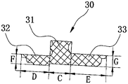
- the injection molding connector 30 is in an inverted "T" shape, and the injection molding connector 30 includes a first connecting part 31 , a second connecting part 32 and a third connecting part 33 integrally formed.
- the second connecting portion 32 is arranged opposite to the third connecting portion 33 , one end of the second connecting portion 32 close to the third connecting portion 33 is fixedly connected to one side of the first connecting portion 31 , and the third connecting portion 33 is close to the second connecting portion 32
- One end of the first connecting part 31 is fixedly connected with the other end.
- the first connecting part 31 is interposed and fixedly connected in the gap 60 between the first transparent board 10 and the second board 20 , so that the first transparent board 10 and the second board 20 face the first transparent board 10
- the second plate 20 is fixed in direction.
- the second connecting portion 32 is against the first light-transmitting plate 10 , and the second connecting portion 32 is bonded to the second surface 13 of the first light-transmitting plate 10 , and the first light-transmitting plate 10 is supported by the second connecting portion 32 and fixed, so that the first light-transmitting plate 10 is fixed in a direction perpendicular to the first light-transmitting plate 10 .
- the third connecting portion 33 is against the second plate 20, and the third connecting portion 33 is attached to the fourth surface 22 of the second plate 20, and the second plate 20 is supported and fixed by the third connecting portion 33, so that the second plate 20
- the second board 20 is fixed in a direction perpendicular to the second board 20 .
- the first connection part 31, the second connection part 32, and the third connection part 33 are fixedly connected or integrally formed, so that the connection between the first light-transmitting plate 10 and the second plate 20 is more stable and reliable, thereby making the window 100 structure is more stable.
- the extension length C of the first connecting portion 31 along the direction from the first light-transmitting plate 10 to the second plate 20 is greater than or equal to 1mm, so as to ensure that the first light-transmitting plate 10
- the strength of the connecting material at the connection with the second plate 20 further makes the connection between the first transparent plate 10 and the second plate 20 more stable and reliable.
- the extension length D of the second connecting portion 32 along the direction from the first light-transmitting plate 10 to the second plate 20 is greater than or equal to 2mm, so as to ensure the bonding between the second connecting portion 32 and the second surface 13 of the first light-transmitting plate 10 area, thereby ensuring the bonding strength between the second connecting portion 32 and the first light-transmitting plate 10 .
- the extension length E of the third connecting portion 33 along the direction from the first light-transmitting plate 10 to the second plate 20 is greater than or equal to 2 mm, so as to ensure the bonding area between the third connecting portion 33 and the fourth surface 22 of the second plate 20, Furthermore, the bonding strength between the third connecting portion 33 and the second board 20 is ensured.
- the extension length D of the second connecting portion 32 along the direction from the first light-transmitting plate 10 to the second plate 20 is greater than or equal to 2.5 mm and less than or equal to 12 mm. In addition to the bonding strength between the transparent plates 10 , it can save material and reduce the weight of the vehicle window 100 .
- the extension length E of the third connecting portion 33 along the direction from the first light-transmitting plate 10 to the second plate 20 is greater than or equal to 2.5 mm and less than or equal to 12 mm, ensuring the adhesion between the third connecting portion 33 and the second plate 20 While increasing the bonding strength, it can save material and reduce the weight of the window 100 .
- the extension length F of the second connecting portion 32 along the direction perpendicular to the second surface 13 of the first light-transmitting plate 10 is greater than or equal to 2mm, and the second connecting portion 32 is fixed to the second
- the first light-transmitting plate 10 is supported by the second connecting portion 32, so that the side of the first light-transmitting plate 10 close to the second plate 20 does not move along the vertical direction of the first light-transmitting plate 10.
- the orientation of the plate 10 is concave.
- the extension length G of the third connecting portion 33 along the direction perpendicular to the fourth surface 22 of the second board 20 is greater than or equal to 2mm, when the third connecting portion 33 is fixed on the fourth surface 22 of the second board 20, the The connecting portion 33 supports the second board 20 so that the side of the second board 20 close to the first light-transmitting board 10 will not be dented in a direction perpendicular to the second board 20 .
- the extension length F of the second connecting portion 32 along the direction perpendicular to the second surface 13 of the first light-transmitting plate 10 is greater than or equal to 2.5 mm and less than or equal to 5 mm
- the third connecting portion 33 extends along the direction perpendicular to the second surface 13 of the first transparent plate 10.
- the extension length G in the direction of the fourth surface 22 of the second plate 20 is greater than or equal to 2.5 mm and less than or equal to 5 mm, while ensuring the connection strength between the first light-transmitting plate 10 and the second plate 20, it can play a role
- the effect of material saving and space occupation is reduced, and the weight of the vehicle window 100 can also be reduced.
- the connection between the first light-transmitting plate 10 and the second plate 20 is achieved.
- the position will not be depressed along the direction perpendicular to the first light-transmitting plate 10, so that the first light-transmitting plate 10 and the second plate 20 are in the same plane, so as to ensure the flatness of the vehicle window 100, thereby ensuring the appearance of the vehicle window 100 Effect.
- the first light-transmitting plate 10 is supported and fixed by the second connecting portion 32, and the second plate 20 is supported and fixed by the third connecting portion 33, Such that the second connecting portion 32 and the third connecting portion 33 have sufficient strength to support the first transparent plate 10 and the second plate 20 .
- the protective sleeve 50 is in the shape of a hollow "I", fixedly installed on the inner side wall of the mounting hole 23, and at least part of the outer side wall of the protective sleeve 50 is in contact with the mounting hole 23. Fitted inside wall.
- the protective sleeve 50 is used to protect and fix the vehicle-mounted antenna 400 and reduce the collision between the vehicle-mounted antenna 400 and the second board 20 , thereby protecting the safety performance of the second board 20 .
- the protection sleeve 50 includes a first protection portion 51 , a second protection portion 52 and a third protection portion 53 integrally formed.
- the second protection portion 52 is disposed opposite to the third protection portion 53 , and the second protection portion 52 and the third protection portion 53 are fixed on opposite ends of the first protection portion 51 .
- the protective sleeve 50 has a central through hole 54 along the axial direction of the protective sleeve 50 (through the first protective part 51, the second protective part 52 and the third protective part 53 in sequence, and the central through hole 54 is coaxially arranged with the mounting hole 23
- the middle through hole 54 is used to accommodate at least part of the vehicle antenna 400
- the protective sleeve 50 is used to fix the vehicle antenna 400 .
- the first protecting portion 51 is annular, and the outer wall of the first protecting portion 51 is attached to and fixedly connected to the inner wall of the mounting hole 23 .
- the ring-shaped first protection portion 51 is attached and fixedly connected to the inner side wall of the mounting hole 23 to prevent the vehicle-mounted antenna 400 from colliding with the second board 20 during installation and causing the second board 20 to be damaged, so that the vehicle-mounted antenna 400 The safety performance is better during the installation process.
- the second protection part 52 is in the shape of a ring, and the second protection part 52 is fixed to one end of the first protection part 51 and extends along the radial direction of the first protection part 51.
- the second protection part 52 protrudes close to the first protection part 51.
- a portion of the second board 20 is attached to and fixedly connected to the third surface 21 of the second board 20 .
- the ring-shaped second protection part 52 is fixed on the third surface 21 of the second plate 20 to form the periphery of the installation hole 23, preventing the water collected on the third surface 21 of the second plate 20 from flowing into the installation hole 23, In order to form waterproof protection for the fourth surface 22 of the second board 20 .
- the third protection part 53 is annular, the third protection part 53 is fixed on the other end of the first protection part 51 and extends along the radial direction of the first protection part 51, and the third protection part 53 is close to the extension of the first protection part 51.
- the protruding part is attached to and fixedly connected with the fourth surface 22 of the second board 20 .
- the ring-shaped third protection part 53 is fixed to the fourth surface 22 of the second board 20 to form the periphery of the mounting hole 23, preventing the vehicle-mounted antenna 400 from colliding with the fourth surface 22 of the second board 20 during the locking process. The collision causes damage to the second board 20 , so that the safety performance during the installation of the vehicle antenna 400 is improved.
- the extension length H of the first protection part 51 in the radial direction of the installation hole 23 is greater than or equal to 1 mm, and the first protection part 51 is used to prevent the vehicle-mounted antenna 400 from The collision between the second boards 20 causes damage to the second boards 20 , which improves the safety performance of the second boards 20 .
- the extension length H of the first protection part 51 in the radial direction of the installation hole 23 is greater than or equal to 2 mm and less than or equal to 5 mm, so as to ensure the safety of the first protection part 51 while wrapping the edge, reduce the amount of materials, reduce the The weight of parts is reduced, thereby reducing the weight of the window 100 .
- the extension length I of the second protection portion 52 in the axial direction of the mounting hole 23 is greater than or equal to 1mm, so that the second protection portion 52 is formed between the end of the second protection portion 52 away from the first protection portion 51 and the third surface 21 of the second plate 20 Step structure, to block the water accumulated on the third surface 21, and then form a waterproof protection structure, so that the water on the third surface 21 of the second board 20 will not flow into the fourth surface 22 of the second board 20 through the installation hole 23 .
- the extension length I of the second protection part 52 in the axial direction of the installation hole 23 is greater than or equal to 2 mm and less than or equal to 5 mm, while ensuring the waterproof function of the second protection part 52, the use of materials is reduced. amount, thereby reducing the weight of the window 100.
- the extension length J of the third protection portion 53 in the axial direction of the mounting hole 23 is greater than or equal to 1 mm, so that the end of the third protection portion 53 away from the first protection portion 51 is formed between the fourth surface 22 of the second plate 20
- the stepped structure prevents the vehicle-mounted antenna 400 from colliding with the fourth surface 22 of the second board 20 during the locking process, causing damage to the second board 20 , so that the safety performance of the vehicle-mounted antenna 400 is better during installation.
- the extension length J of the third protection part 53 in the axial direction of the installation hole 23 is greater than or equal to 2.5 mm and less than or equal to 5 mm, so as to ensure the safety of the third protection part 53 during the installation process of the vehicle antenna 400 While improving the safety performance, the amount of materials used is reduced, thereby reducing the weight of the vehicle window 100 .
- the second embodiment provided by the present application is substantially the same as the first embodiment, the difference lies in the structure of the injection molded connector 30 .
- the injection molding connector 30 lacks the second connecting portion 32 and the third connecting portion 33 , and the injection molding connector 30 only includes the first connecting portion 31 .
- the amount of materials used is reduced, thereby reducing the weight of the vehicle window 100 .
- the third embodiment is substantially the same as the first embodiment, the difference lies in the structure of the protective sleeve 50 .
- the protection sleeve 50 lacks the second protection portion 52 and the third protection portion 53 , and the protection sleeve 50 only includes the first protection portion 51 .
- the amount of materials used is reduced, thereby reducing the weight of the vehicle window 100 .
- the fourth embodiment provided by the present application is substantially the same as the third embodiment, except that the injection molding connector 30 and the protective sleeve 50 are different.
- the injection molding connector 30 lacks the second connecting portion 32 and the third connecting portion 33 , and the injection molding connector 30 only includes the first connecting portion 31 .
- the protection sleeve 50 lacks the second protection portion 52 and the third protection portion 53 , and the protection sleeve 50 only includes the first protection portion 51 . The amount of materials used is reduced, thereby reducing the weight of the vehicle window 100 .
Landscapes
- Engineering & Computer Science (AREA)
- Mechanical Engineering (AREA)
- Remote Sensing (AREA)
- Chemical & Material Sciences (AREA)
- Combustion & Propulsion (AREA)
- Transportation (AREA)
- Architecture (AREA)
- Structural Engineering (AREA)
- Fittings On The Vehicle Exterior For Carrying Loads, And Devices For Holding Or Mounting Articles (AREA)
- Window Of Vehicle (AREA)
Abstract
一种车窗,包括:第一透光板(10)、第二板(20)及注塑件(30),第二板与第一透光板间隔设置形成间隙;第二板具有安装孔,安装孔用于收容车载天线;注塑连接件,设于间隙,注塑连接件固定连接于第一透光板与第二板之间。还包括一种汽车。该车窗及汽车可降低制造难度。
Description
本申请要求于2021年06月22日提交中国专利局、申请号为202110690015.5、申请名称为“车窗及汽车”的中国专利申请的优先权,其全部内容通过引用结合在本申请中。
本申请涉及汽车技术领域,具体涉及一种车窗及汽车。
汽车天窗安装于车顶,能够有效地使车内空气流通,便于新鲜空气的进入。同时,汽车天窗可以开阔视野进而满足移动摄影摄像的拍摄需求。常见的汽车天窗包括手动天窗、外滑式天窗、内藏式天窗、全景天窗、多功能天窗等类型。
随着汽车消费升级和集成化技术的发展,汽车天窗越来越向低端车型普及,而且附件集成化也越来越高。现有的汽车天窗中,车载天线通常是在车身外支架上开孔,进而将信号传导到车内设备。但是车身外支架制造工序复杂,且车身外支架的与天窗玻璃的外观色泽差异较大,无法实现汽车天窗外观全玻璃。
因此,如何设计一种能够降低制造难度且能实现全景天窗的外观效果的车窗及汽车成为亟需解决的问题。
发明内容
为解决上述技术问题,本申请提供了一种能够降低制造难度且能实现全景天窗的外观效果的车窗及汽车。
一方面,本申请提供了一种车窗的成型方法,包括:
第一透光板;
第二板,与所述第一透光板间隔设置形成间隙;所述第二板具有安装孔,所述安装孔用于收容车载天线;及
注塑连接件,设于所述间隙,所述注塑连接件固定连接于所述第一透光板与所述第二板之间。
在一种可能的实施方式中,所述第一透光板包括相对设置的第一面与第二面,所述第二板包括相对设置的第三面与第四面;所述注塑连接件包括一体成型的第一连接部、第二连接部及第三连接部,所述第一连接部设于所述间隙,所述第二连接部与第二面固定连接,所述第三连接部与所述第四面固定连接。
进一步地,所述第一透光板的周侧壁围设形成一收容槽,所述收容槽用于收容所述第二板,且所述收容槽的内侧壁与所述第二板间隔设置形成所述间隙,所述第一连接部设于所述间隙;所述收容槽的第一开口位于所述第一面,所述收容槽的第二开口位于所述第二面,所述收容槽的第三开口位于所述第一透光板的周侧壁。
进一步地,所述第一连接部沿所述第一透光板到所述第二板的方向上的延伸长度大于或者等于1mm;所述第二连接部沿所述第一透光板到所述第二板的方向上的延伸长度大于或者等于2mm;所述第三连接部沿所述第一透光板到所述第二板的方向上的延伸长度大于或者等 于2mm。
进一步地,所述第二连接部沿垂直所述第一透光板的方向上的延伸厚度大于或者等于2mm;所述第三连接部沿垂直所述第二板的方向上的延伸厚度大于或者等于2mm。
在一种可能的实施方式中,所述第一透光板在垂直所述第一透光板的方向上的延伸厚度小于或者等于5mm。
进一步地,所述第一透光板为夹层玻璃,所述夹层玻璃包括至少两层透光玻璃及至少一个中间膜,每相邻的两层透光玻璃之间对应设有至少一个所述中间膜。
在一种可能的实施方式中,所述第二板在垂直所述第二板方向上的延伸厚度小于或者等于5mm。
进一步地,所述第二板为单层玻璃。
进一步地,所述车窗还包括保护套筒,所述保护套筒固定穿设于所述安装孔。
更进一步地,所述保护套筒包括一体成型的第一保护部、第二保护部及第三保护部;所述第二保护部与所述第三保护部分别设于所述第一保护部的相对两端;所述第二保护部固定于所述第三面上,所述第三保护部固定于所述第四面上。
更近一步地,所述第一保护部沿垂直所述安装孔的轴向上的延伸厚度大于或者等于1mm,所述第二保护部沿所述安装孔的径向上的延伸厚度大于或者等于1mm,所述第三保护部沿所述安装孔的轴向上的厚度延伸大于或者等于1mm。
另一方面,本申请还提供了一种汽车,包括所述车窗;所述汽车还包括车载天线、车身支架及粘接件,所述粘接件粘接于所述车窗与所述车身支架之间;所述车载天线贯穿所述车窗,用于拦截高频电波并传输给所述汽车的接收机,以对载波解调。
相较于传统的金属外板、金属内板及夹层玻璃的车窗结构,本申请通过第一透光板与第二板注塑连接成一个整体,其结构更加简单、制造更方便、成本更低。由于第一透光板与第二板皆具有透光性,使得车窗达到全景的效果、用户使用体验感更好。由于第一透光板不适合开设车载天线的安装孔,本申请通过在第二板上开设车载天线的安装孔,在降低影响第一透光板的外观效果的同时,使得车窗安装车载天线更加便捷,实现车载天线位置的结构优化。
为了更清楚地说明本申请实施例的技术方案,下面将对实施例中所需要使用的附图作简单地介绍。
图1是本申请实施例提供的一种汽车的示意图;
图2是本申请第一实施例提供的一种车窗的剖面图;
图3是本申请实施例提供的一种车窗的示意图;
图4是本申请实施例提供的一种第一透光板的示意图;
图5是本申请第一实施例提供的一种第一透光板与第二板的装配图;
图6是本申请实施例提供的一种第二板的示意图;
图7是本申请第一实施例提供的一种注塑连接件的剖面图;
图8是本申请第一实施例提供的一种第二板与保护套筒的装配图;
图9是本申请第一实施例提供的一种保护套筒的剖面图;
图10是本申请第二实施例提供的一种车窗的剖面图;
图11是本申请第二实施例提供的一种第一透光板与第二板的装配图;
图12是本申请第三实施例提供的一种车窗的剖面图;
图13是本申请第三实施例提供的一种第二板与保护套筒的装配图;
图14是本申请第四实施例提供的一种车窗的剖面图。
下面将结合本申请实施例中的附图,对本申请实施例中的技术方案进行清楚、完整地描述。显然,所描述的实施例仅仅是本申请一部分实施例,而不是全部的实施例。基于本申请中的实施例,本领域普通技术人员在没有付出创造性劳动前提下所获得的所有其他实施例,都属于本申请保护的范围。
下面以汽车天窗应用于汽车上为例,对本申请的技术方案进行详述。
请参阅图1,汽车500包括车窗100、粘接件200、车身支架300及车载天线400,粘接件200粘接于车窗100与车身支架300之间,从而使车窗100与车身支架300固定连接,以实现汽车500全景天窗的效果。车载天线400贯穿并固定于车窗100上,用于拦截高频电波并传输给汽车500的接收机。通过车载天线400对载波进行解调,使得汽车500内部的接收机接收外部信号。
可以理解的,本申请提供的车窗100的应用包括但不限于汽车500等其他机车。
本申请实施例中的粘接件200的材质为白胶(PU胶水,聚氨脂树脂),在其他实施方式中,粘接件200的材质包括但不限于PU胶水等其他具有粘性的材料。
本申请提供的第一实施例,请参阅图2,车窗100包括第一透光板10、第二板20、注塑连接件30、天线盖40及保护套筒50。
请参阅图3及图4,第一透光板10的周侧面围设形成收容腔11,收容腔11的开口位于透光板10的周侧面上。收容腔11用于收容第二板20,第二板20与收容腔11的侧壁间隔设置形成间隙60。
请参阅图1、图4及图5,第一透光板10包括相对设置的第一面12和第二面13,第一面12朝向汽车500的外部设置,第二面13朝向汽车500的内部设置。第一透光板10沿第一面12的垂线方向上的厚度A小于或者等于5mm,以使第一透光板10在满足结构强度的同时,减轻零件重量,降低车窗100的重量。第一透光板10包括但不限于多层玻璃等。收容腔11贯穿第一面12与第二面13。
本申请实施方式中,第一透光板10为夹层玻璃,夹层玻璃是由两片或多片玻璃,之间夹了一层或多层有机聚合物中间膜,经过特殊的高温预压(或抽真空)及高温高压工艺处理后,使玻璃和中间膜永久粘合为一体的复合玻璃产品。可以理解,第一透光板10也可以为单层玻璃或者其他类型的透光板。
请参阅图1、图5及图6,第二板20包括相对设置的第三面21和第四面22,第三面21朝向汽车500的外部设置,第四面22朝向汽车500的内部设置。第二板20具有贯穿第三面21与第四面22的安装孔23。安装孔23用于汽车500在安装车载天线400时收容至少部分的车载天线400,车载天线400固定于第二板20上。第二板20沿第三面21的垂线方向上的厚度B小于或者等于5mm,以使第二板20在满足结构强度的同时,减轻零件重量,降低车窗100的重量。
本申请实施方式中,第二板20为单层玻璃。可以理解的,第二板20包括但不限于单层玻璃、高光亮板等其他板材。单层玻璃具有透光性,能实现全景天窗的效果。高光亮板的外 表面具有高亮的特性,耶能实现全景天窗的外观效果。
请参阅图3及图5,注塑连接件30设于收容腔11的间隙60中,进而以使第一透光板10与第二板20通过注塑连接件30固定连接形成整体结构。
请参阅图2、图5,注塑连接件30呈倒“T”字型,注塑连接件30包括一体成型的第一连接部31、第二连接部32及第三连接部33。第二连接部32与第三连接部33相对设置,第二连接部32靠近第三连接部33的一端与第一连接部31的一侧固定连接,第三连接部33靠近第二连接部32的一端与第一连接部31的另一端固定连接。
第一连接部31夹设并固定连接于第一透光板10与第二板20之间的间隙60中,以使第一透光板10与第二板20在第一透光板10朝向第二板20方向上固定。第二连接部32与第一透光板10抵持,且第二连接部32与第一透光板10的第二面13贴合,通过第二连接部32对第一透光板10支撑与固定,以使第一透光板10在垂直于第一透光板10的方向上固定。第三连接部33与第二板20抵持,且第三连接部33与第二板20的第四面22贴合,通过第三连接部33对第二板20支撑与固定,以使第二板20在垂直于第二板20的方向上固定。
通过第一连接部31、第二连接部32及第三连接部33固定连接或者一体成型设置,使得第一透光板10与第二板20之间的连接更加稳定可靠,进而使得车窗100的结构更加稳定。
具体的,请参阅图2、图5及图7,第一连接部31沿第一透光板10到第二板20方向上的延伸长度C大于或者等于1mm,以保证第一透光板10与第二板20的连接处连接材料的强度,进而使得第一透光板10与第二板20之间的连接更加稳定可靠。第二连接部32沿第一透光板10到第二板20方向上的延伸长度D大于或者等于2mm,以保证第二连接部32与第一透光板10的第二面13的粘接面积,进而保证第二连接部32与第一透光板10之间的粘接强度。第三连接部33沿第一透光板10到第二板20方向上的延伸长度E大于或者等于2mm,以保证第三连接部33与第二板20的第四面22的粘接面积,进而保证第三连接部33与第二板20之间的粘接强度。
本申请实施方式中,第二连接部32沿第一透光板10到第二板20方向上的延伸长度D大于或者等于2.5mm且小于或者等于12mm,在保证第二连接部32与第一透光板10之间的粘接强度的同时,能够起到节省材料的作用,而且还能减车窗100的重量。第三连接部33沿第一透光板10到第二板20方向上的延伸长度E大于或者等于2.5mm且小于或者等于12mm,在保证第三连接部33与第二板20之间的粘接强度的同时,能够起到节省材料的作用,而且还能减车窗100的重量。
请参阅图2、图5及图7,第二连接部32沿垂直第一透光板10的第二面13的方向上的延伸长度F大于或者等于2mm,在第二连接部32固定于第一透光板10的第二面13时,通过第二连接部32支撑第一透光板10,以使第一透光板10靠近第二板20的一侧不会沿垂直第一透光板10的方向凹陷。第三连接部33沿垂直第二板20的第四面22的方向上的延伸长度G大于或者等于2mm,在第三连接部33固定于第二板20的第四面22时,通过第三连接部33支撑第二板20,以使第二板20靠近第一透光板10的一侧不会沿垂直第二板20的方向凹陷。
本申请实施方式中,第二连接部32沿垂直第一透光板10的第二面13的方向上的延伸长度F大于或者等于2.5mm且小于或者等于5mm,第三连接部33沿垂直第二板20的第四面22的方向上的延伸长度G大于或者等于2.5mm且小于或者等于5mm,在保证第一透光板10与第二板20之间的连接强度的同时,能够起到节省材料、减小占用空间的作用,而且还能减轻车窗100的重量。
通过第二连接部32对第一透光板10的支撑及固定作用,以及第三连接部33对第二板 20的支撑及固定作用,使得第一透光板10与第二板20的连接处不会沿垂直第一透光板10的方向凹陷,进而使得第一透光板10与第二板20在同一个平面内,以保证车窗100的平整度,进而保证车窗100的外观效果。同时,在车载天线400的安装过程中,由于车载天线400有一定的重量,通过第二连接部32支撑并固定第一透光板10,以及第三连接部33支撑并固定第二板20,以使第二连接部32与第三连接部33有足够的强度支撑第一透光板10和第二板20。
请参阅图1、图2及图8,保护套筒50呈中空的“工”字型,固定安装于安装孔23的内侧壁上,且保护套筒50的至少部分外侧壁与安装孔23的内侧壁贴合。保护套筒50用于保护固定车载天线400并减小车载天线400与第二板20之间的碰撞,进而保护第二板20的安全性能。
保护套筒50包括一体成型的第一保护部51、第二保护部52及第三保护部53。第二保护部52与第三保护部53相对设置,第二保护部52与第三保护部53固定于第一保护部51的相对两端。保护套筒50具有沿保护套筒50的轴向(依次贯穿第一保护部51、第二保护部52及第三保护部53的中间通孔54,中间通孔54与安装孔23同轴设置。在汽车500安装车载天线400时,中间通孔54用于收容至少部分的车载天线400,保护套筒50用于固定车载天线400。
第一保护部51呈圆环状,第一保护部51的外侧壁与安装孔23的内侧壁贴合并固定连接。通过圆环状的第一保护部51与安装孔23的内侧壁贴合并固定连接,防止车载天线400在安装的过程中与第二板20发生碰撞导致第二板20损坏,以使车载天线400的安装过程中安全性能更好。
第二保护部52呈圆环状,第二保护部52固定于第一保护部51的一端并沿第一保护部51的径向延伸,第二保护部52靠近第一保护部51的伸出的部分与第二板20的第三面21贴合并固定连接。通过圆环状的第二保护部52固定于第二板20的第三面21形成安装孔23的周沿,防止聚集在第二板20的第三面21上的水流入安装孔23内,以对第二板20的第四面22形成防水保护。
第三保护部53呈圆环状,第三保护部53固定于第一保护部51的另一端并沿第一保护部51的径向延伸,第三保护部53靠近第一保护部51的伸出的部分与第二板20的第四面22贴合并固定连接。通过圆环状的第三保护部53固定于第二板20的第四面22形成安装孔23的周沿,防止车载天线400在锁付的过程中与第二板20的第四面22产生碰撞导致第二板20损坏,以使车载天线400的安装过程中安全性能更好。
具体的,请参阅图1、图2、图8及图9,第一保护部51在安装孔23的径向上的延伸长度H大于或者等于1mm,第一保护部51用于防止车载天线400与第二板20之间碰撞导致第二板20损坏,提高第二板20的安全性能。
本申请实施例中,第一保护部51在安装孔23的径向上的延伸长度H大于或者等于2mm且小于或者等于5mm,以保证第一保护部51包边安全的同时,降低材料用量,降低零件重量,进而减小车窗100的重量。
第二保护部52在安装孔23的轴向上的延伸长度I大于或者等于1mm,以使第二保护部52远离第一保护部51的一端与第二板20的第三面21之间形成台阶结构,以阻挡第三面21上聚集的水,进而形成防水保护结构,以使第二板20的第三面21上的水不会通过安装孔23流入第二板20的第四面22。
本申请实施例中,第二保护部52在安装孔23的轴向上的延伸长度I大于或者等于2mm 且小于或者等于5mm,在保证第二保护部52的防水功能的同时,降低材料的使用量,进而使得车窗100的重量减小。
第三保护部53在安装孔23的轴向上的延伸长度J大于或者等于1mm,以使第三保护部53远离第一保护部51的一端与第二板20的第四面22之间形成台阶结构,以防止车载天线400在锁付的过程中与第二板20的第四面22产生碰撞导致第二板20损坏,以使车载天线400的安装过程中安全性能更好。
本申请实施例中,第三保护部53在安装孔23的轴向上的延伸长度J大于或者等于2.5mm且小于或者等于5mm,在保证第三保护部53在车载天线400的安装过程中的安全性能的同时,降低材料的使用量,进而使得车窗100的重量减小。
本申请提供的第二实施例,第二实施例与第一实施例大致相同,不同之处在于注塑连接件30的结构。
请参阅图7、图10及图11,注塑连接件30缺少第二连接部32和第三连接部33,注塑连接件30仅仅包括第一连接部31。降低材料的使用量,进而使得车窗100的重量减小。
本申请提供的第三实施例,第三实施例与第一实施例大致相同,不同之处在于保护套筒50的结构。
请参阅图9、图12及图13,保护套筒50缺少第二保护部52和第三保护部53,保护套筒50仅仅包括第一保护部51。降低材料的使用量,进而使得车窗100的重量减小。
本申请提供的第四实施例,第四实施例与第三实施例大致相同,不同之处在于注塑连接件30与保护套筒50。
请参阅图7、图9及图14,注塑连接件30缺少第二连接部32和第三连接部33,注塑连接件30仅仅包括第一连接部31。保护套筒50缺少第二保护部52和第三保护部53,保护套筒50仅仅包括第一保护部51。降低材料的使用量,进而使得车窗100的重量减小。
以上是本申请的部分实施方式,应当指出,对于本技术领域的普通技术人员来说,在不脱离本申请原理的前提下,还可以做出若干改进和润饰,这些改进和润饰也视为本申请的保护范围。
Claims (13)
- 一种车窗,其特征在于,包括:第一透光板;第二板,与所述第一透光板间隔设置形成间隙;所述第二板具有安装孔,所述安装孔用于收容车载天线;及注塑连接件,设于所述间隙,所述注塑连接件固定连接于所述第一透光板与所述第二板之间。
- 如权利要求1所述的车窗,其特征在于,所述第一透光板包括相对设置的第一面与第二面,所述第二板包括相对设置的第三面与第四面;所述注塑连接件包括一体成型的第一连接部、第二连接部及第三连接部,所述第一连接部设于所述间隙,所述第二连接部与第二面固定连接,所述第三连接部与所述第四面固定连接。
- 如权利要求2所述的车窗,其特征在于,所述第一透光板的周侧壁围设形成一收容槽,所述收容槽用于收容所述第二板,且所述收容槽的内侧壁与所述第二板间隔设置形成所述间隙,所述第一连接部设于所述间隙;所述收容槽的第一开口位于所述第一面,所述收容槽的第二开口位于所述第二面,所述收容槽的第三开口位于所述第一透光板的周侧壁。
- 如权利要求2所述的车窗,其特征在于,所述第一连接部沿所述第一透光板到所述第二板的方向上的延伸长度大于或者等于1mm;所述第二连接部沿所述第一透光板到所述第二板的方向上的延伸长度大于或者等于2mm;所述第三连接部沿所述第一透光板到所述第二板的方向上的延伸长度大于或者等于2mm。
- 如权利要求2所述的车窗,其特征在于,所述第二连接部沿垂直所述第一透光板的方向上的延伸厚度大于或者等于2mm;所述第三连接部沿垂直所述第二板的方向上的延伸厚度大于或者等于2mm。
- 如权利要求1所述的车窗,其特征在于,所述第一透光板在垂直所述第一透光板的方向上的延伸厚度小于或者等于5mm。
- 如权利要求6所述的车窗,其特征在于,所述第一透光板为夹层玻璃,所述夹层玻璃包括至少两层透光玻璃及至少一个中间膜,每相邻的两层透光玻璃之间对应设有至少一个所述中间膜。
- 如权利要求1所述的车窗,其特征在于,所述第二板在垂直所述第二板方向上的延伸厚度小于或者等于5mm。
- 如权利要求8所述的车窗,其特征在于,所述第二板为单层玻璃。
- 如权利要求3所述的车窗,其特征在于,所述车窗还包括保护套筒,所述保护套筒固定穿设于所述安装孔。
- 如权利要求10所述的车窗,其特征在于,所述保护套筒包括一体成型的第一保护部、第二保护部及第三保护部;所述第二保护部与所述第三保护部分别设于所述第一保护部的相对两端;所述第二保护部固定于所述第三面上,所述第三保护部固定于所述第四面上。
- 如权利要求11所述的车窗,其特征在于,所述第一保护部沿垂直所述安装孔的轴向上的延伸厚度大于或者等于1mm,所述第二保护部沿所述安装孔的径向上的延伸厚度大于或者等于1mm,所述第三保护部沿所述安装孔的轴向上的延伸厚度大于或者等于1mm。
- 一种汽车,其特征在于,包括如权利要求1~12任意一项所述的车窗;所述汽车还包括车载天线、车身支架及粘接件,所述粘接件粘接于所述车窗与所述车身支架之间;所述车载天线贯穿所述车窗,用于拦截高频电波并传输给所述汽车的接收机,以对载波解调。
Priority Applications (2)
| Application Number | Priority Date | Filing Date | Title |
|---|---|---|---|
| EP22827521.0A EP4329091A4 (en) | 2021-06-22 | 2022-06-20 | AUTOMOBILE AND AUTO WINDOW |
| US18/528,226 US12466242B2 (en) | 2021-06-22 | 2023-12-04 | Vehicle window and vehicle |
Applications Claiming Priority (2)
| Application Number | Priority Date | Filing Date | Title |
|---|---|---|---|
| CN202110690015.5 | 2021-06-22 | ||
| CN202110690015.5A CN113427982B (zh) | 2021-06-22 | 2021-06-22 | 车窗及汽车 |
Related Child Applications (1)
| Application Number | Title | Priority Date | Filing Date |
|---|---|---|---|
| US18/528,226 Continuation US12466242B2 (en) | 2021-06-22 | 2023-12-04 | Vehicle window and vehicle |
Publications (1)
| Publication Number | Publication Date |
|---|---|
| WO2022268028A1 true WO2022268028A1 (zh) | 2022-12-29 |
Family
ID=77757142
Family Applications (1)
| Application Number | Title | Priority Date | Filing Date |
|---|---|---|---|
| PCT/CN2022/099847 Ceased WO2022268028A1 (zh) | 2021-06-22 | 2022-06-20 | 车窗及汽车 |
Country Status (4)
| Country | Link |
|---|---|
| US (1) | US12466242B2 (zh) |
| EP (1) | EP4329091A4 (zh) |
| CN (1) | CN113427982B (zh) |
| WO (1) | WO2022268028A1 (zh) |
Families Citing this family (1)
| Publication number | Priority date | Publication date | Assignee | Title |
|---|---|---|---|---|
| CN113427982B (zh) * | 2021-06-22 | 2022-07-19 | 福耀玻璃工业集团股份有限公司 | 车窗及汽车 |
Citations (7)
| Publication number | Priority date | Publication date | Assignee | Title |
|---|---|---|---|---|
| US20030061765A1 (en) * | 2001-03-02 | 2003-04-03 | Asahi Glass Company Limited | Window glass for an automobile and glass recycling method |
| JP2005041358A (ja) * | 2003-07-23 | 2005-02-17 | Omega Techno Modeling:Kk | 自動車窓用装飾板及びその装着方法並びにその取付セット |
| JP2007001353A (ja) * | 2005-06-21 | 2007-01-11 | Sanryuusha:Kk | 自動車用の防犯ドア及び、この防犯ドアを備えた自動車 |
| CN207875360U (zh) * | 2018-01-08 | 2018-09-18 | 解云 | 一种多功能的汽车天窗 |
| CN209126665U (zh) * | 2018-11-30 | 2019-07-19 | 上海毓恬冠佳汽车零部件有限公司 | 一种汽车天窗上实现天线功能的机构 |
| CN211139463U (zh) * | 2019-10-21 | 2020-07-31 | 神通科技集团股份有限公司 | 一种汽车侧窗集成d柱结构 |
| CN113427982A (zh) * | 2021-06-22 | 2021-09-24 | 福耀玻璃工业集团股份有限公司 | 车窗及汽车 |
Family Cites Families (10)
| Publication number | Priority date | Publication date | Assignee | Title |
|---|---|---|---|---|
| JP5125756B2 (ja) * | 2008-05-15 | 2013-01-23 | セントラル硝子株式会社 | 自動車用ガラスアンテナ性能を考慮した車体構造 |
| CN104476855B (zh) * | 2014-12-01 | 2016-01-20 | 福耀玻璃工业集团股份有限公司 | 一种带孔的夹层玻璃 |
| BR112017027449B8 (pt) * | 2015-11-17 | 2022-12-27 | Saint Gobain | Painel de vidro compósito com um furo para montagem, método para produzir um painel de vidro compósito, e, uso de um elemento polimérico |
| JP2018083432A (ja) * | 2016-11-21 | 2018-05-31 | アイシン精機株式会社 | 車両用ルーフ装置 |
| CO2017007445A1 (es) * | 2017-03-29 | 2018-07-19 | Agp America Sa | Laminado para automotores con agujero |
| US20190210546A1 (en) * | 2018-01-05 | 2019-07-11 | Byton Limited | Vehicle roof struture with integrated electrical connectivity module and methods for making the same |
| CN111655480B (zh) * | 2018-01-24 | 2022-12-09 | 中央硝子株式会社 | 具有信息获取系统用的框架的玻璃 |
| EP3833564B1 (en) * | 2018-08-07 | 2022-06-29 | Central Glass Company, Limited | Methods of reinforcing openings in glass and products formed therefrom |
| CN211764831U (zh) * | 2020-01-09 | 2020-10-27 | 福耀玻璃工业集团股份有限公司 | 一种车窗玻璃,窗户组件及车辆 |
| CN111987409B (zh) * | 2020-08-21 | 2021-11-19 | 福耀玻璃工业集团股份有限公司 | 天线玻璃及车辆 |
-
2021
- 2021-06-22 CN CN202110690015.5A patent/CN113427982B/zh active Active
-
2022
- 2022-06-20 WO PCT/CN2022/099847 patent/WO2022268028A1/zh not_active Ceased
- 2022-06-20 EP EP22827521.0A patent/EP4329091A4/en active Pending
-
2023
- 2023-12-04 US US18/528,226 patent/US12466242B2/en active Active
Patent Citations (7)
| Publication number | Priority date | Publication date | Assignee | Title |
|---|---|---|---|---|
| US20030061765A1 (en) * | 2001-03-02 | 2003-04-03 | Asahi Glass Company Limited | Window glass for an automobile and glass recycling method |
| JP2005041358A (ja) * | 2003-07-23 | 2005-02-17 | Omega Techno Modeling:Kk | 自動車窓用装飾板及びその装着方法並びにその取付セット |
| JP2007001353A (ja) * | 2005-06-21 | 2007-01-11 | Sanryuusha:Kk | 自動車用の防犯ドア及び、この防犯ドアを備えた自動車 |
| CN207875360U (zh) * | 2018-01-08 | 2018-09-18 | 解云 | 一种多功能的汽车天窗 |
| CN209126665U (zh) * | 2018-11-30 | 2019-07-19 | 上海毓恬冠佳汽车零部件有限公司 | 一种汽车天窗上实现天线功能的机构 |
| CN211139463U (zh) * | 2019-10-21 | 2020-07-31 | 神通科技集团股份有限公司 | 一种汽车侧窗集成d柱结构 |
| CN113427982A (zh) * | 2021-06-22 | 2021-09-24 | 福耀玻璃工业集团股份有限公司 | 车窗及汽车 |
Non-Patent Citations (1)
| Title |
|---|
| See also references of EP4329091A4 * |
Also Published As
| Publication number | Publication date |
|---|---|
| CN113427982B (zh) | 2022-07-19 |
| EP4329091A4 (en) | 2024-10-09 |
| EP4329091A1 (en) | 2024-02-28 |
| CN113427982A (zh) | 2021-09-24 |
| US12466242B2 (en) | 2025-11-11 |
| US20240100914A1 (en) | 2024-03-28 |
Similar Documents
| Publication | Publication Date | Title |
|---|---|---|
| US11731899B2 (en) | Method for producing vehicular structure and method for producing protective film-attached transparent substrate | |
| CN110087923B (zh) | 带密封构件的窗玻璃 | |
| US20240424766A1 (en) | Glazing with insert | |
| CN217259842U (zh) | 一种嵌件注塑式无缝集成激光雷达的汽车饰件 | |
| JP4754044B2 (ja) | 衝突試験に対する耐性の高い合わせガラス | |
| WO2022268028A1 (zh) | 车窗及汽车 | |
| WO2019235449A1 (ja) | 合わせガラス | |
| JP7145240B2 (ja) | 複合ガラスペイン | |
| JP2882694B2 (ja) | 車両ドア窓用複層ガラス | |
| CN217753431U (zh) | 车门组件以及车辆 | |
| CN204801464U (zh) | 多功能车窗 | |
| US20190081392A1 (en) | Antenna assembly | |
| WO2022218069A1 (zh) | 一种车辆天窗和车辆 | |
| US20240217313A1 (en) | Vehicle window assembly and vehicle | |
| CN103459174B (zh) | 带框体的窗用板材及带框体的窗用板材的制造方法 | |
| CN116811546A (zh) | 窗口模块、具有其的机动车以及顶部模块 | |
| CN219487144U (zh) | 玻璃组件、天幕组件以及车辆 | |
| CN111180855A (zh) | 天线组件 | |
| CN222832916U (zh) | 发动机罩及车辆 | |
| CN115027228B (zh) | 一种树脂尾门 | |
| CN216783426U (zh) | 内饰板组件、车内组件和车辆 | |
| CN120156263B (zh) | 车窗玻璃组件和车辆 | |
| CN223030760U (zh) | 用于车辆的天幕总成和车辆 | |
| CN118103208A (zh) | 具有嵌件的嵌装玻璃 | |
| CN216331851U (zh) | 一种汽车后窗装饰板总成 |
Legal Events
| Date | Code | Title | Description |
|---|---|---|---|
| 121 | Ep: the epo has been informed by wipo that ep was designated in this application |
Ref document number: 22827521 Country of ref document: EP Kind code of ref document: A1 |
|
| WWE | Wipo information: entry into national phase |
Ref document number: 2022827521 Country of ref document: EP |
|
| ENP | Entry into the national phase |
Ref document number: 2022827521 Country of ref document: EP Effective date: 20231124 |
|
| NENP | Non-entry into the national phase |
Ref country code: DE |