WO2022270272A1 - 建築物 - Google Patents
建築物 Download PDFInfo
- Publication number
- WO2022270272A1 WO2022270272A1 PCT/JP2022/022562 JP2022022562W WO2022270272A1 WO 2022270272 A1 WO2022270272 A1 WO 2022270272A1 JP 2022022562 W JP2022022562 W JP 2022022562W WO 2022270272 A1 WO2022270272 A1 WO 2022270272A1
- Authority
- WO
- WIPO (PCT)
- Prior art keywords
- floor
- gap
- wall
- pillar
- story
- Prior art date
- Legal status (The legal status is an assumption and is not a legal conclusion. Google has not performed a legal analysis and makes no representation as to the accuracy of the status listed.)
- Ceased
Links
Images


Classifications
-
- E—FIXED CONSTRUCTIONS
- E04—BUILDING
- E04C—STRUCTURAL ELEMENTS; BUILDING MATERIALS
- E04C2/00—Building elements of relatively thin form for the construction of parts of buildings, e.g. sheet materials, slabs, or panels
- E04C2/44—Building elements of relatively thin form for the construction of parts of buildings, e.g. sheet materials, slabs, or panels characterised by the purpose
- E04C2/52—Building elements of relatively thin form for the construction of parts of buildings, e.g. sheet materials, slabs, or panels characterised by the purpose with special adaptations for auxiliary purposes, e.g. serving for locating conduits
- E04C2/521—Building elements of relatively thin form for the construction of parts of buildings, e.g. sheet materials, slabs, or panels characterised by the purpose with special adaptations for auxiliary purposes, e.g. serving for locating conduits serving for locating conduits; for ventilating, heating or cooling
- E04C2/525—Building elements of relatively thin form for the construction of parts of buildings, e.g. sheet materials, slabs, or panels characterised by the purpose with special adaptations for auxiliary purposes, e.g. serving for locating conduits serving for locating conduits; for ventilating, heating or cooling for heating or cooling
-
- E—FIXED CONSTRUCTIONS
- E04—BUILDING
- E04B—GENERAL BUILDING CONSTRUCTIONS; WALLS, e.g. PARTITIONS; ROOFS; FLOORS; CEILINGS; INSULATION OR OTHER PROTECTION OF BUILDINGS
- E04B1/00—Constructions in general; Structures which are not restricted either to walls, e.g. partitions, or floors or ceilings or roofs
- E04B1/62—Insulation or other protection; Elements or use of specified material therefor
- E04B1/74—Heat, sound or noise insulation, absorption, or reflection; Other building methods affording favourable thermal or acoustical conditions, e.g. accumulating of heat within walls
Definitions
- the present invention relates to buildings.
- each story blocks upstream and downstream, making it difficult to spread comfortable air throughout the building. Therefore, even if an atrium is provided in order to secure upstream and downstream, the floor area on the upper floors is greatly reduced, which is not preferable.
- the present invention was made in order to solve such problems, and its object is to provide a building that can secure upstream and downstream without greatly reducing the floor area of the upper floors. It is in.
- the building according to the present invention is an upper layer having a floor; a floor directly below the floor; a pillar provided on the floor; an outer wall attached to the pillar and having one side facing the exterior space and the other side facing the interior space; an air-conditioning panel adopted for at least a part of the outer wall and exhibiting an air-conditioning effect in the indoor space;
- the floor has a gap within the thickness range of the pillar between the floor and the outer wall, and through the gap, air can be circulated between the floor immediately below and the upper floor.
- the floor is not limited to what actually functions as a floor for people to walk on or use as a bed, but also means the lower structure on the floor.
- FIG. 1 It is a perspective view showing an example of a building concerning an embodiment of the present invention. It is a perspective view which shows the structure when a wall part is removed from the building which concerns on this embodiment. It is a partially enlarged view of FIG. 1, (a) is a partially enlarged view of the second story, and (b) is a partially enlarged view showing a state where the floor of the second story is removed. It is a partially enlarged view according to a modification, (a) is a partially enlarged view of the second story, and (b) is a partially enlarged view showing a state where the floor of the second story is removed. It is another partially enlarged view of the second layer.
- FIG. 6 is a perspective view showing a state in which the roll screen shown in FIG. 5 is stretched;
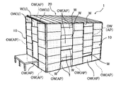
- FIG. 1 is a perspective view showing an example of a building according to an embodiment of the present invention.
- the wall portion 10 includes a window portion W and an outer wall OW.
- a window glass or the like is attached to the window portion W.
- the window W may be of a slide opening/closing type, a depth opening/closing type, or a fixed type that cannot be opened/closed.
- the window W may be provided with external wall penetrating elements such as a ventilation port, an exhaust port, a lead-in for a power line, a telephone line, and the like, and an antenna wiring.
- the outer wall OW is directly or indirectly attached to a pillar (see symbol P in FIGS. 3 and 4), and one side faces the external space.
- the outer wall OW employs a so-called air conditioning panel AP.
- the air-conditioning panel AP exerts an air-conditioning effect on the other side of the room, and corresponds to, for example, a heat pipe panel or a refrigerator panel.
- a heat pipe panel is a panel that allows heat transmission from one side to the other side and suppresses heat transmission from the other side to the other side.
- This heat pipe panel has a working fluid inside, the working fluid evaporates on one side and takes heat, and the vapor generated by the evaporation reaches the other side and discards the heat of condensation from the other side. It is a panel that allows heat transmission from one side to the other side.
- This heat pipe panel has an inclined structure inside, and has a structure in which the working fluid condensed on the other side returns to the one side by its own weight.
- the heat pipe panel has a heat insulating layer whose inside is a vacuum or the like, suppresses heat flow from the other side to the one side, and has high heat insulating properties.
- a refrigerator panel is a panel that exhibits a refrigeration function by absorption or adsorption, and includes a regenerator, a condenser, an evaporator, and an absorber that constitute an absorption refrigeration cycle, or an adsorber that constitutes an adsorption refrigeration cycle.
- a condenser, and an evaporator are plate-shaped.
- the refrigerator panel also has a vacuum insulation part (insulation layer) and the like, and has high insulation performance.
- the air-conditioning panel AP is used in all of the outer wall OW except for the triangular or trapezoidal upper portion U. may be adopted only for
- the air conditioning panel AP is not limited to the heat pipe panel and the refrigerator panel, but may be of other types as long as it exerts an air conditioning effect on the indoor side, such as a panel that simply receives power supply and exerts a cooling effect with the electric power. , may be
- FIG. 2 is a perspective view showing the structure when the wall section 10 is removed from the building 1 according to this embodiment.
- the building 1 according to the present embodiment is composed of four floors: a first floor H1 and a second floor H2 serving as living room spaces, an underfloor floor UF, and an attic BH.
- the first hierarchy H1 is the so-called first floor.
- An underfloor story UF is provided below the floor F1 of the first story H1.
- the underfloor story UF is a story whose bottom surface is the foundation of the building 1 .
- the second hierarchy H2 is a so-called second floor.
- the second story H2 has a structure in which floor surfaces of a plurality of heights are provided in one story, a so-called skip floor, and a step ST having a gap between the floors F2 is provided.
- An attic BH is provided above the ceiling section C of the second story H2.
- the ceiling portion C is indicated by a dashed line in FIG. 2 and corresponds to the floor portion of the attic BH.
- the floor of the attic BH is also referred to as C.
- the attic BH also called an attic, is a story surrounded by the ceiling C of the second story H2 and the roof 20 shown in FIG.
- the second floor H2 may have no ceiling C and may be a space integrated with the attic BH.
- the underfloor floor UF and the attic BH basically do not have an inner wall, or even if an inner wall exists, an opening is formed, preferably forming one space.
- the first floor H1 and the second floor H2 do not have inner walls.
- a corridor is provided between the outer walls OW (see Fig. 1) that face each other so that a horizontal flow can be generated, or a sliding door that can be opened is provided so that residents can communicate with each other. It is preferable to be able to do so.
- FIG. 3 is a partially enlarged view of FIG. 1, (a) is a partially enlarged view of the second floor H2, and (b) is a partial view of the second floor H2 with the floor F2 removed. It is an enlarged view.
- the floor F2 of the second floor H2 has a gap S within the thickness range of the pillar P (less than the width of the pillar) with respect to the outer wall OW. Therefore, in the building 1 according to the present embodiment, air can be circulated through the gap S between the second floor H2 and the first floor H1 directly above the floor F2.
- the beam width W1 of the trunk portion BD is made narrower than the column width W2, and the narrowed portion is formed as a gap S between the outer wall OW and the beam width W1. becomes. Accordingly, the gap S can be formed by adjusting the beam width W1 of the trunk portion BD and the size of the floor portion F2 without adding a new structure to provide the gap S.
- the girder BD is a concept that includes not only the so-called girth that divides each floor, but also the foundation provided on the foundation in the first story H1.
- the beam width of the foundation similarly for the first floor H1 to form a gap S between the outer wall OW and the floor F1.
- a gap is provided between the foundation on which the foundation rests and the foundation so that air can circulate with the underfloor story UF through the gap S, and a gap between the outer wall OW and the foundation is prevented.
- Appropriate measures such as providing a sealing member are required.
- the gap S is provided in all of the upper hierarchies H1, H2, and BH except for the lowest hierarchy, ie, the underfloor hierarchy UF, which is the lowest hierarchy among multiple hierarchies (four hierarchies). Note that the gap S may be provided in at least one of the upper hierarchies H1, H2, and BH.
- FIG. 4A and 4B are partially enlarged views of the second floor H2, and FIG. 4B is a partially enlarged view of the second floor H2 with the floor F2 removed. It is a part enlarged view.
- the gap S is not limited to being formed by narrowing the beam width W1 of the trunk portion BD.
- a building 1 (see FIG. 1) has a furring strip BE attached to the outside of a pillar P, as shown in FIG. 4(a).
- the outer wall OW is attached to the furring strip BE, and is attached to the pillar P via the furring strip BE. Therefore, the thickness of the furring strip BE is formed as a gap S between the furring strip BE and the outer wall OW.
- the beam width W1 see FIG. 3
- the narrowness of the trunk portion BD affects the strength. can be prevented.
- the gap S may also be formed using furring strips BE for the first story H1 according to the modification.
- the furring strip BE may be used to form the gap S in the attic BH as well.
- the gap S shown in FIG. 4 is provided in all of the upper hierarchies H1, H2, and BH, but it may be provided in any one of the upper hierarchies H1, H2, and BH.
- the furring strip BE may be a horizontal member as shown in FIG.
- the gap S shown in FIG. 3 is adopted for the outer wall OW facing a certain direction in the building 1
- the gap S shown in FIG. 4 is adopted for the outer wall OW facing another direction. You may make it That is, both the clearance S shown in FIG. 3 and the clearance S shown in FIG. 4 may be employed in one building 1 .
- FIG. 5 is another partially enlarged view of the second layer H2.
- a building 1 (see FIG. 1) has an atrium AT that runs through two or more stories including at least a story with a gap S (see FIGS. 3 and 4) among a plurality of stories. may be provided.
- the atrium portion AT has a size equal to or greater than the thickness of the pillar P (see FIGS. 3 and 4).
- a ceiling fan (pressure difference generating means) SF is provided in the atrium AT.
- the ceiling fan SF has blades arranged horizontally, and the rotation of the blades generates a pressure difference between the upper side (one side) and the lower side (the other side) of the blades.
- the building 1 according to the present embodiment can generate upstream and downstream in the atrium AT by rotating the ceiling fan SF in the atrium AT. Furthermore, in conjunction with the generation of upstream and downstream airflow in the atrium AT, it is also possible to generate an upstream and downstream airflow using the gap S, so that smooth air circulation in the building 1 can be achieved.
- the atrium AT shown in FIG. 5 penetrates the ceiling C (see FIG. 2) of the second story H2 and extends to the attic BH (see FIG. 2). That is, the atrium AT shown in FIG. 5 runs through three floors.
- the first direction faces the outer wall OW (see FIG. 1, etc.) on the second floor H2, and the handrail HR is provided in the second direction opposite to the first direction.
- the atrium portion AT is provided with waist walls SW in third and fourth directions that intersect the first direction and the second direction at right angles.
- the atrium AT Since the atrium AT has such a configuration, the atrium AT is the second floor H2 (middle floor) excluding the attic BH and the first floor H1 (the uppermost and lowermost floors) of the three floors running through it.
- a space SP is formed where the atrium AT and the second story H2 face each other. In other words, the space SP is a common part of the space in the second floor H2 and the space in the atrium AT.
- a plurality of roll screens (blocking means) RS that can be extended from the bottom to the top are provided.
- a first roll screen RS1 is provided on the floor F2 in the second direction in which the handrail HR is provided.
- second and third roll screens RS2 and RS3 are provided above the waist wall SW in the third and fourth directions in which the waist wall SW is provided.
- Plate-like handrails HRB are provided above the second and third roll screens RS2 and RS3, respectively, to hide the second and third roll screens RS2 and RS3.
- FIG. 6 is a perspective view showing a state in which the roll screen RS shown in FIG. 5 is stretched.
- the first to third roll screens RS1 to RS3 can be extended to the vicinity of the ceiling C (see FIG. 2) of the second story H2.
- the space SP (see FIG. 5) facing the atrium AT and the second floor H2 is closed.
- the first to third roll screens RS1 to RS3 are each stretched to the vicinity of the ceiling C (see FIG. 2) of the second floor H2, thereby separating the space SP from the space in the second floor H2.
- the atrium AT directly connects the first story H1 and the attic BH.
- the upstream and downstream pass through without blowing into the second story H2.
- first to third roll screens RS1 to RS3 are not limited to being extended to the ceiling section C of the second floor H2, and can be stopped halfway. Therefore, the space SP can be partially closed and the rest left open, and the upstream/downstream distribution and air collection height on the second story H2 can be arbitrarily determined.
- the building 1 shown in FIG. 1 has a gap S between it and the outer wall OW. For this reason, the air of the outer wall OW that has been air-conditioned by the air-conditioning panel AP moves through the gaps S in a plurality of stories as upstream and downstream.
- the ceiling fan SF when the atrium AT has a means for generating a pressure difference such as a ceiling fan SF, the ceiling fan SF generates an upstream/downstream movement in the atrium AT, which in turn causes an upstream/downstream movement through the gap S. can be done. For example, if a downward flow is generated in the atrium AT, an upward flow in the opposite direction can be generated in the gap S accordingly.
- the building 1 is formed in four stories, and gaps S are also provided in the floor C of the attic BH and the floor F1 of the first story H1.
- the attic BH and the underfloor floor UF which can be used, generally have no or few inner walls and are not equipped with furniture, etc. A current can be suitably generated.
- the attic BH and the underfloor floor UF it is possible to preferably perform air circulation.
- At least one of the floors F1, F2, and C of the upper floors H1, H2, and BH has a gap within the thickness range of the pillar P with respect to the outer wall OW. S, and through the gaps S, air circulation between the floor immediately below and the floor directly above the floors F1, F2, and C is possible. Therefore, according to the building 1, the upstream and downstream can be secured through the gap S without providing an atrium AT having a size larger than a predetermined size. Therefore, upstream and downstream can be secured without significantly reducing the floor area of the upper floors.
- the building 1 also has a girth BD with a beam width W1 narrower than that of the pillar P, and a gap S is formed between the girth BD and the outer wall OW. Therefore, there is no need to add a new structure to provide the gap S, and by adjusting the beam width W1 of the girth BD, the upper and lower floors can be secured without significantly reducing the floor area. can be done.
- the gap S is formed by attaching the outer wall OW to the pillar P via the furring strip BE, the gap S is formed by using the furring strip BE without modifying the pillar P or the furring strip BD. can be formed, and upstream and downstream can be ensured without affecting the strength of the building 1 or the like.
- the air-conditioning panel AP has a heat insulating layer that insulates the interior of the room from the exterior space, and does not have an interior material on the interior side of the gap S, so that the interior surface facing the interior space is directly exposed to the interior air. ing. For this reason, the room air can be directly conditioned on the room surface, and the room air can be preferably circulated through the gap S.
- the building 1 since the building 1 has the ceiling fan SF and the atrium AT that runs through the story including the floor where the gap S is provided, the atrium AT can be used to generate upstream and downstream. Upstream and downstream movement using the gap S can also be encouraged. Therefore, it can contribute to smooth air circulation.
- the atrium AT is an element that reduces the floor area of the upper floors, but the structure corresponding to the atrium AT can be omitted by the amount of the gap S, so the floor area of the upper floors can be greatly reduced. does not reach
- the building 1 includes a roll screen RS on the second floor H2 of the atrium AT for closing the space SP where the atrium AT and the second floor H2 face each other.
- a roll screen RS on the second floor H2 of the atrium AT for closing the space SP where the atrium AT and the second floor H2 face each other.
- the floor immediately above the gap S is the attic BH, it is possible to use the attic BH where walls, furniture, etc. are not normally installed, and the horizontal flow that is essential both upstream and downstream can be suitably generated. can contribute to
- the layer immediately below the gap S is the underfloor layer UF, and since the underfloor layer UF is usually not provided with inner walls, furniture, etc., it can contribute to the suitable generation of horizontal flow along with upstream and downstream. Further, even if the underfloor story UF is blocked by the foundation, providing an opening in a part of the foundation can contribute to the favorable generation of horizontal flow.
- the atrium AT faces the outer wall OW in the first direction.
- the gap S may be within the thickness range of the pillar P that is the thickest.
- the pillar P extends from the floor directly below H1 to the upper floor H2 through the floor F2. It doesn't have to be penetrating.
- the means for blocking the space SP is not limited to the roll screen RS, and may be another object such as a slidable wall.
- the means for generating the pressure difference is not limited to the propeller type like the ceiling fan SF. is not limited to
- the atrium AT may utilize a space in which stairs are provided.
- the floor has a gap (S) within the thickness range of the pillar between the floor and the outer wall, and through the gap, the air can be circulated between the floor immediately below and the upper floor.
- pressure difference generating means for generating a pressure difference between one side and the other side; Any one of the above [1] to [4], further comprising: an atrium (AT) that runs through the upper story and the directly below story, has a size greater than the thickness of the column, and is provided with the pressure difference generating means.
- the building described in 1. [6] further comprising at least one layer above the upper layer or below the immediately lower layer; The atrium extends through at least three floors, Blocking means (roll screen RS, The building according to [5] above, further comprising first to third roll screens RS1 to RS3).
- Blocking means roll screen RS, The building according to [5] above, further comprising first to third roll screens RS1 to RS3).
- BH attic
- UF underfloor floor
Landscapes
- Engineering & Computer Science (AREA)
- Architecture (AREA)
- Structural Engineering (AREA)
- Civil Engineering (AREA)
- Life Sciences & Earth Sciences (AREA)
- Mechanical Engineering (AREA)
- Sustainable Development (AREA)
- Physics & Mathematics (AREA)
- Acoustics & Sound (AREA)
- Electromagnetism (AREA)
- Building Environments (AREA)
- Vending Machines For Individual Products (AREA)
- Buildings Adapted To Withstand Abnormal External Influences (AREA)
Abstract
Description
床部を有する上位階層と、
前記床部の直下に位置する直下階層と、
前記床部に設けられた柱と、
前記柱に取り付けられ、一方面が外部空間に面し、他方面が室内空間に面する外壁と、
前記外壁の少なくとも一部に採用され、前記室内空間に空調効果を発揮する空調パネルと、を備え、
前記床部は、前記外壁との間に、前記柱の厚み範囲内の隙間を有し、かつ、前記隙間を通じて、前記直下階層と前記上位階層との空気循環が可能に構成される。
。
[1] 床部(C,F1,F2)を有する上位階層(H1,H2,BH)と、
前記床部の直下に位置する直下階層(H1)と、
前記床部に設けられた柱(P)と、
前記柱に取り付けられ、一方面が外部空間に面し、他方面が室内空間に面する外壁(OW)と、
前記外壁の少なくとも一部に採用され、前記室内空間に空調効果を発揮する空調パネル(AP)と、を備え、
前記床部は、前記外壁との間に、前記柱の厚み範囲内の隙間(S)を有し、かつ、前記隙間を通じて、前記直下階層と前記上位階層との空気循環が可能に構成される、
建築物(1)。
[2] 前記柱よりも梁幅の狭い胴差部(BD)を有し、
前記隙間(S)は、前記胴差部と前記外壁との間に形成されている
上記[1]に記載の建築物。
[3] 前記柱の外側に対して取り付けられた胴縁(BE)を有し、
前記隙間(S)は、前記外壁が前記胴縁を介して前記柱に取り付けられることで形成される
上記[1]又は[2]に記載の建築物。
[4] 前記空調パネルは、前記室内空間と前記外部空間とを断熱する断熱層を有し、室内面に内装材を有することなく前記室内面が直接室内空気にさられている
上記[1]から[3]のいずれか一に記載の建築物。
[5] 一方側と他方側とで圧力差を発生させる圧力差発生手段(シーリングファンSF)と、
前記上位階層及び前記直下階層を縦貫すると共に前記柱の厚み以上の大きさを有し、前記圧力差発生手段が設けられる吹き抜け部(AT)と
をさらに備える上記[1]から[4]のいずれか一に記載の建築物。
[6] 前記上位階層の上又は前記直下階層の下に、少なくとも1階層をさらに備え、
前記吹き抜け部は、少なくとも3階層を縦貫するものであって、
縦貫される階層のうち最も上及び最も下を除く中間階層(第2階層H2)に、前記吹き抜け部と前記中間階層とが面する空間部(SP)を塞ぐための閉塞手段(ロールスクリーンRS、第1~第3ロールスクリーンRS1~RS3)をさらに備える
上記[5]に記載の建築物。
[7] 前記上位階層は、小屋裏(BH)である
上記[1]から[6]のいずれか一に記載の建築物。
[8] 前記直下階層は、床下階層(UF)である
上記[1]から[6]のいずれか一に記載の建築物。
10 :壁部
AP :空調パネル
AT :吹き抜け部
BD :胴差部
BE :胴縁
BH :小屋裏
C,F1,F2 :床部
H1 :第1階層
H2 :第2階層
H1,H2,BH :上位階層
OW :外壁
P :柱
RS :ロールスクリーン(閉塞手段)
S :隙間
SF :シーリングファン(圧力差発生手段)
SP :空間部
UF :床下階層
W1 :梁幅
W2 :柱幅
Claims (8)
- 床部を有する上位階層と、
前記床部の直下に位置する直下階層と、
前記床部に設けられた柱と、
前記柱に取り付けられ、一方面が外部空間に面し、他方面が室内空間に面する外壁と、
前記外壁の少なくとも一部に採用され、前記室内空間に空調効果を発揮する空調パネルと、を備え、
前記床部は、前記外壁との間に、前記柱の厚み範囲内の隙間を有し、かつ、前記隙間を通じて、前記直下階層と前記上位階層との空気循環が可能に構成される、
建築物。 - 前記柱よりも梁幅の狭い胴差部を有し、
前記隙間は、前記胴差部と前記外壁との間に形成されている
請求項1に記載の建築物。 - 前記柱の外側に対して取り付けられた胴縁を有し、
前記隙間は、前記外壁が前記胴縁を介して前記柱に取り付けられることで形成される
請求項1に記載の建築物。 - 前記空調パネルは、前記室内空間と前記外部空間とを断熱する断熱層を有し、室内面に内装材を有することなく前記室内面が直接室内空気にさられている
請求項1に記載の建築物。 - 一方側と他方側とで圧力差を発生させる圧力差発生手段と、
前記上位階層及び前記直下階層を縦貫すると共に前記柱の厚み以上の大きさを有し、前記圧力差発生手段が設けられる吹き抜け部と
をさらに備える請求項1に記載の建築物。 - 前記上位階層の上又は前記直下階層の下に、少なくとも1階層をさらに備え、
前記吹き抜け部は、少なくとも3階層を縦貫するものであって、
縦貫される階層のうち最も上及び最も下を除く中間階層に、前記吹き抜け部と前記中間階層とが面する空間部を塞ぐための閉塞手段をさらに備える
請求項5に記載の建築物。 - 前記上位階層は、小屋裏である
請求項1から請求項6のいずれか1項に記載の建築物。 - 前記直下階層は、床下階層である
請求項1から請求項6のいずれか1項に記載の建築物。
Priority Applications (4)
| Application Number | Priority Date | Filing Date | Title |
|---|---|---|---|
| CN202280036320.5A CN117355651A (zh) | 2021-06-25 | 2022-06-02 | 建筑物 |
| AU2022298132A AU2022298132A1 (en) | 2021-06-25 | 2022-06-02 | Building |
| EP22828190.3A EP4361367A4 (en) | 2021-06-25 | 2022-06-02 | BUILDING |
| US18/515,069 US20240084595A1 (en) | 2021-06-25 | 2023-11-20 | Building |
Applications Claiming Priority (2)
| Application Number | Priority Date | Filing Date | Title |
|---|---|---|---|
| JP2021105690A JP2023004157A (ja) | 2021-06-25 | 2021-06-25 | 建築物 |
| JP2021-105690 | 2021-06-25 |
Related Child Applications (1)
| Application Number | Title | Priority Date | Filing Date |
|---|---|---|---|
| US18/515,069 Continuation US20240084595A1 (en) | 2021-06-25 | 2023-11-20 | Building |
Publications (1)
| Publication Number | Publication Date |
|---|---|
| WO2022270272A1 true WO2022270272A1 (ja) | 2022-12-29 |
Family
ID=84545661
Family Applications (1)
| Application Number | Title | Priority Date | Filing Date |
|---|---|---|---|
| PCT/JP2022/022562 Ceased WO2022270272A1 (ja) | 2021-06-25 | 2022-06-02 | 建築物 |
Country Status (6)
| Country | Link |
|---|---|
| US (1) | US20240084595A1 (ja) |
| EP (1) | EP4361367A4 (ja) |
| JP (1) | JP2023004157A (ja) |
| CN (1) | CN117355651A (ja) |
| AU (1) | AU2022298132A1 (ja) |
| WO (1) | WO2022270272A1 (ja) |
Citations (6)
| Publication number | Priority date | Publication date | Assignee | Title |
|---|---|---|---|---|
| JPS62160344A (ja) * | 1986-01-08 | 1987-07-16 | ナショナル住宅産業株式会社 | 壁内の換気構造 |
| JP2002070192A (ja) * | 2000-08-31 | 2002-03-08 | Osamu Ogoshi | 建物の壁構造 |
| JP2002332705A (ja) * | 2001-05-08 | 2002-11-22 | Topics:Kk | 通気壁構造及び壁パネル |
| JP2008134043A (ja) | 2006-10-27 | 2008-06-12 | Canon Inc | 伝熱制御機構および伝熱制御機構を搭載した燃料電池システム |
| JP2017106289A (ja) * | 2015-12-11 | 2017-06-15 | 株式会社 ホームリサーチ | 空調システム、空調方法、及びプログラム |
| JP2021105690A (ja) | 2019-12-27 | 2021-07-26 | キヤノン株式会社 | 撮像装置 |
Family Cites Families (9)
| Publication number | Priority date | Publication date | Assignee | Title |
|---|---|---|---|---|
| DE1810493A1 (de) * | 1968-11-22 | 1971-01-21 | Gartner & Co J | Gebaeudeaussenwand |
| DK68586D0 (da) * | 1985-06-03 | 1986-02-12 | System Feed Inc | Fremgangsmaade og anlaeg til luftfornyelse eller luftventilation |
| DE3843067C2 (de) * | 1987-06-27 | 1997-01-23 | Habermann Karl A Dipl Ing | Verfahren zur Wärmerückgewinnung bei einem Bausystem in Skelettbauweise |
| JP3563901B2 (ja) * | 1996-10-31 | 2004-09-08 | 角次 古畑 | 建造物の暖冷房システム |
| JP4553649B2 (ja) * | 2003-08-29 | 2010-09-29 | 株式会社サトコウ | ユニット工法建築物 |
| GB0622926D0 (en) * | 2006-11-16 | 2006-12-27 | Polypipe Building Products Ltd | A building system |
| CN101799196B (zh) * | 2010-02-27 | 2013-04-03 | 张宗楼 | 新型浅层地能、太阳能、风能一体化建筑空调系统 |
| CN103712360A (zh) * | 2012-10-08 | 2014-04-09 | 陈紫微 | 太阳能绝热空调板 |
| CN111535440B (zh) * | 2020-05-18 | 2021-07-09 | 浙江奥腾建设工程有限公司 | 一种防潮地下室 |
-
2021
- 2021-06-25 JP JP2021105690A patent/JP2023004157A/ja not_active Ceased
-
2022
- 2022-06-02 WO PCT/JP2022/022562 patent/WO2022270272A1/ja not_active Ceased
- 2022-06-02 AU AU2022298132A patent/AU2022298132A1/en not_active Abandoned
- 2022-06-02 EP EP22828190.3A patent/EP4361367A4/en not_active Withdrawn
- 2022-06-02 CN CN202280036320.5A patent/CN117355651A/zh active Pending
-
2023
- 2023-11-20 US US18/515,069 patent/US20240084595A1/en not_active Abandoned
Patent Citations (6)
| Publication number | Priority date | Publication date | Assignee | Title |
|---|---|---|---|---|
| JPS62160344A (ja) * | 1986-01-08 | 1987-07-16 | ナショナル住宅産業株式会社 | 壁内の換気構造 |
| JP2002070192A (ja) * | 2000-08-31 | 2002-03-08 | Osamu Ogoshi | 建物の壁構造 |
| JP2002332705A (ja) * | 2001-05-08 | 2002-11-22 | Topics:Kk | 通気壁構造及び壁パネル |
| JP2008134043A (ja) | 2006-10-27 | 2008-06-12 | Canon Inc | 伝熱制御機構および伝熱制御機構を搭載した燃料電池システム |
| JP2017106289A (ja) * | 2015-12-11 | 2017-06-15 | 株式会社 ホームリサーチ | 空調システム、空調方法、及びプログラム |
| JP2021105690A (ja) | 2019-12-27 | 2021-07-26 | キヤノン株式会社 | 撮像装置 |
Non-Patent Citations (1)
| Title |
|---|
| See also references of EP4361367A4 |
Also Published As
| Publication number | Publication date |
|---|---|
| EP4361367A1 (en) | 2024-05-01 |
| JP2023004157A (ja) | 2023-01-17 |
| US20240084595A1 (en) | 2024-03-14 |
| CN117355651A (zh) | 2024-01-05 |
| EP4361367A4 (en) | 2024-11-06 |
| AU2022298132A1 (en) | 2023-12-07 |
Similar Documents
| Publication | Publication Date | Title |
|---|---|---|
| US8397449B2 (en) | Double window having ventilation function | |
| JP4855349B2 (ja) | 建物の排気構造、建物、及び二重外壁構造 | |
| JP3746216B2 (ja) | 換気機構付きカーテンウォールユニットおよび建物の換気構造 | |
| JP2015200121A (ja) | 建物 | |
| WO2022270272A1 (ja) | 建築物 | |
| JP5191962B2 (ja) | カーテンウォール | |
| US20100287856A1 (en) | Double window having horizontal cross-ventilation function | |
| JP6368123B2 (ja) | 建物におけるダクト設置構造 | |
| JP5755946B2 (ja) | 建物の空調設備 | |
| JP5684499B2 (ja) | 建物の通気構造 | |
| KR200419514Y1 (ko) | 이중 창호 | |
| JP2017141628A (ja) | ダブルスキンカーテンウォール | |
| WO2022255016A1 (ja) | 建築物 | |
| JP7702798B2 (ja) | 改修方法及び建物 | |
| JP2006152665A (ja) | 防音換気建具 | |
| JP2004137730A (ja) | カーテンウォール | |
| Eslamirad et al. | Double Skin Facades in Use, a Study of Configuration and Performance of Double Skin Façade, Case Studies Some Office Buildings | |
| JP7031916B1 (ja) | 空調装置用中空構造体 | |
| JP7805116B2 (ja) | 建具 | |
| JP2000329373A (ja) | 下方向の換気および上方向の換気が可能な建物ならびにその建物の冷暖房方法 | |
| JP7620511B2 (ja) | 住宅のリフォーム方法及び換気方法 | |
| JP5133615B2 (ja) | 建物 | |
| JP7429534B2 (ja) | 建物 | |
| CN2921240Y (zh) | 通风隔声窗 | |
| JP6529922B2 (ja) | 二世帯住宅の空調システム |
Legal Events
| Date | Code | Title | Description |
|---|---|---|---|
| 121 | Ep: the epo has been informed by wipo that ep was designated in this application |
Ref document number: 22828190 Country of ref document: EP Kind code of ref document: A1 |
|
| WWE | Wipo information: entry into national phase |
Ref document number: 202280036320.5 Country of ref document: CN Ref document number: 2022298132 Country of ref document: AU Ref document number: AU2022298132 Country of ref document: AU |
|
| WWE | Wipo information: entry into national phase |
Ref document number: 202347079230 Country of ref document: IN |
|
| ENP | Entry into the national phase |
Ref document number: 2022298132 Country of ref document: AU Date of ref document: 20220602 Kind code of ref document: A |
|
| WWE | Wipo information: entry into national phase |
Ref document number: 2022828190 Country of ref document: EP |
|
| NENP | Non-entry into the national phase |
Ref country code: DE |
|
| ENP | Entry into the national phase |
Ref document number: 2022828190 Country of ref document: EP Effective date: 20240125 |