WO2023002988A1 - 通信方法 - Google Patents
通信方法 Download PDFInfo
- Publication number
- WO2023002988A1 WO2023002988A1 PCT/JP2022/028079 JP2022028079W WO2023002988A1 WO 2023002988 A1 WO2023002988 A1 WO 2023002988A1 JP 2022028079 W JP2022028079 W JP 2022028079W WO 2023002988 A1 WO2023002988 A1 WO 2023002988A1
- Authority
- WO
- WIPO (PCT)
- Prior art keywords
- mbs
- user equipment
- cell group
- secondary cell
- receiving
- Prior art date
- Legal status (The legal status is an assumption and is not a legal conclusion. Google has not performed a legal analysis and makes no representation as to the accuracy of the status listed.)
- Ceased
Links
Images


Classifications
-
- H—ELECTRICITY
- H04—ELECTRIC COMMUNICATION TECHNIQUE
- H04W—WIRELESS COMMUNICATION NETWORKS
- H04W72/00—Local resource management
- H04W72/30—Resource management for broadcast services
-
- H—ELECTRICITY
- H04—ELECTRIC COMMUNICATION TECHNIQUE
- H04W—WIRELESS COMMUNICATION NETWORKS
- H04W4/00—Services specially adapted for wireless communication networks; Facilities therefor
- H04W4/06—Selective distribution of broadcast services, e.g. multimedia broadcast multicast service [MBMS]; Services to user groups; One-way selective calling services
-
- H—ELECTRICITY
- H04—ELECTRIC COMMUNICATION TECHNIQUE
- H04W—WIRELESS COMMUNICATION NETWORKS
- H04W72/00—Local resource management
- H04W72/12—Wireless traffic scheduling
- H04W72/1263—Mapping of traffic onto schedule, e.g. scheduled allocation or multiplexing of flows
- H04W72/1273—Mapping of traffic onto schedule, e.g. scheduled allocation or multiplexing of flows of downlink data flows
-
- H—ELECTRICITY
- H04—ELECTRIC COMMUNICATION TECHNIQUE
- H04W—WIRELESS COMMUNICATION NETWORKS
- H04W76/00—Connection management
- H04W76/20—Manipulation of established connections
-
- H—ELECTRICITY
- H04—ELECTRIC COMMUNICATION TECHNIQUE
- H04W—WIRELESS COMMUNICATION NETWORKS
- H04W76/00—Connection management
- H04W76/10—Connection setup
- H04W76/15—Setup of multiple wireless link connections
-
- H—ELECTRICITY
- H04—ELECTRIC COMMUNICATION TECHNIQUE
- H04W—WIRELESS COMMUNICATION NETWORKS
- H04W76/00—Connection management
- H04W76/40—Connection management for selective distribution or broadcast
Definitions
- the present disclosure relates to a communication method used in a mobile communication system.
- NR New Radio
- 5G fifth generation
- 4G fourth generation
- NR has features such as high speed, large capacity, high reliability, and low delay.
- MBS multicast/broadcast service
- CA carrier aggregation
- DC dual connectivity in which the user equipment communicates with two base stations at the same time
- MN master node
- SN secondary node
- Non-Patent Document 1 proposes enabling MBS transmission from a secondary cell group (SCG) managed by an SN to a user equipment.
- SCG secondary cell group
- the communication method according to the first aspect is a communication method used in a mobile communication system that supports multicast/broadcast service (MBS), wherein the user equipment performing dual connectivity (DC) or carrier aggregation (CA) is the DC communicating with a master cell group in the CA or a primary cell in the CA; and performing MBS reception by the user equipment from a secondary cell group in the DC or a secondary cell in the CA.
- the communicating includes communicating MBS-related information regarding the MBS reception from the secondary cell group or the secondary cell to the master cell group or the primary cell.
- the communication method according to the second aspect is a communication method used in a mobile communication system that supports multicast/broadcast service (MBS), and the user equipment performs dual connectivity (DC) or carrier aggregation (CA).
- MBS multicast/broadcast service
- CA carrier aggregation
- the user equipment uses a radio network temporary identifier (RNTI) for MBS reception in a secondary cell group in the DC or a secondary cell in the CA, a physical downlink control channel in the secondary cell group or the secondary cell and the user equipment continuing to monitor the PDCCH using the RNTI even if the secondary cell group or the secondary cell is deactivated.
- RNTI radio network temporary identifier
- a communication method is a communication method used in a mobile communication system that supports multicast/broadcast service (MBS), in which a user device that performs dual connectivity (DC) receives Alternatively, identifying a cell group that provides an MBS session that the user is interested in receiving from the master cell group and the secondary cell group, and the user equipment sends an MBS interest notification regarding the MBS session to the identified cell group. and sending a
- a communication method is a communication method used in a mobile communication system that supports multicast/broadcast service (MBS), and a master node that manages a master cell group in dual connectivity (DC) performed by a user equipment is , communicating with a secondary node managing a secondary cell group in said DC, and performing MBS transmission from said master cell group or said secondary cell group to said user equipment.
- the communicating includes communicating with the secondary node an MBS Interest Notification regarding an MBS session that the user equipment is receiving or interested in receiving.
- the communication method according to the fifth aspect is a communication method used in a mobile communication system that supports multicast/broadcast service (MBS), and a secondary node that manages a secondary cell group in dual connectivity (DC) with the user equipment is , communicating with a master node managing a master cell group in said DC; and said secondary node performing MBS transmissions to said user equipment.
- the communicating includes transmitting from the secondary node to the master node MBS configuration information indicating configuration for the user equipment to receive MBS in the secondary cell group.
- FIG. 1 is a diagram showing the configuration of a mobile communication system according to an embodiment
- FIG. It is a figure which shows the structure of UE (user apparatus) which concerns on embodiment.
- It is a diagram showing the configuration of a gNB (base station) according to the embodiment.
- FIG. 2 is a diagram showing the configuration of a protocol stack of a user plane radio interface that handles data
- FIG. 2 is a diagram showing the configuration of a protocol stack of a radio interface of a control plane that handles signaling (control signals)
- FIG. 4 is a diagram illustrating an overview of MBS traffic distribution according to an embodiment
- FIG. 4 illustrates a first operational scenario according to an embodiment
- FIG. 4 illustrates a first operational scenario according to an embodiment
- FIG 11 illustrates a second operating scenario according to an embodiment; It is a figure which shows the 1st example of operation
- FIG. 13 is a diagram illustrating operations of a MAC entity of a UE according to the sixth embodiment; It is a figure which shows 6th Example. It is a figure which shows 7th Example. It is a figure which shows 8th Example. It is a figure which shows 9th Example.
- the current 3GPP technical specifications do not define a mechanism for the user equipment to receive MBS from the SCG in DC or the secondary cell (SCell) in CA. Therefore, it is difficult for the user equipment to efficiently receive MBS from SCG in DC or SCell in CA.
- the present disclosure provides a communication method that enables user equipment to efficiently receive MBS from SCG in DC or SCell in CA.
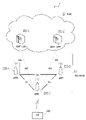
- FIG. 1 is a diagram showing the configuration of a mobile communication system according to an embodiment.
- the mobile communication system 1 complies with the 3GPP standard 5th generation system (5GS: 5th Generation System).
- 5GS will be described below as an example, an LTE (Long Term Evolution) system may be at least partially applied to the mobile communication system.
- 6G systems may be at least partially applied in mobile communication systems.
- the mobile communication system 1 includes a user equipment (UE: User Equipment) 100, a 5G radio access network (NG-RAN: Next Generation Radio Access Network) 10, and a 5G core network (5GC: 5G Core Network) 20.
- UE User Equipment
- NG-RAN Next Generation Radio Access Network
- 5GC 5G Core Network
- the NG-RAN 10 may be simply referred to as the RAN 10 below.
- the 5GC 20 is sometimes simply referred to as a core network (CN) 20 .
- CN core network
- the UE 100 is a mobile wireless communication device.
- the UE 100 may be any device as long as it is used by the user. (including chipset), sensors or devices installed in sensors, vehicles or devices installed in vehicles (Vehicle UE), aircraft or devices installed in aircraft (Aerial UE).
- the NG-RAN 10 includes a base station (called “gNB” in the 5G system) 200.
- the gNBs 200 are interconnected via an Xn interface, which is an interface between base stations.
- the gNB 200 manages one or more cells.
- the gNB 200 performs radio communication with the UE 100 that has established connection with its own cell.
- the gNB 200 has a radio resource management (RRM) function, a user data (hereinafter simply referred to as “data”) routing function, a measurement control function for mobility control/scheduling, and the like.
- RRM radio resource management
- a “cell” is used as a term indicating the minimum unit of a wireless communication area.
- a “cell” is also used as a term indicating a function or resource for radio communication with the UE 100 .
- One cell belongs to one carrier frequency.
- the gNB can also be connected to the EPC (Evolved Packet Core), which is the LTE core network.
- EPC Evolved Packet Core
- LTE base stations can also connect to 5GC.
- An LTE base station and a gNB may also be connected via an inter-base station interface.
- 5GC20 includes AMF (Access and Mobility Management Function) and UPF (User Plane Function) 300.
- AMF performs various mobility control etc. with respect to UE100.
- AMF manages the mobility of UE 100 by communicating with UE 100 using NAS (Non-Access Stratum) signaling.
- the UPF controls data transfer.
- AMF and UPF are connected to gNB 200 via NG interface, which is a base station-core network interface.
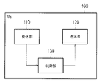
- FIG. 2 is a diagram showing the configuration of the UE 100 (user equipment) according to the embodiment.
- UE 100 includes a receiver 110 , a transmitter 120 and a controller 130 .
- the receiving unit 110 and the transmitting unit 120 constitute a wireless communication unit that performs wireless communication with the gNB 200 .
- the receiving unit 110 performs various types of reception under the control of the control unit 130.
- the receiver 110 includes an antenna and a receiver.
- the receiver converts a radio signal received by the antenna into a baseband signal (received signal) and outputs the baseband signal (received signal) to control section 130 .
- the transmission unit 120 performs various transmissions under the control of the control unit 130.
- the transmitter 120 includes an antenna and a transmitter.
- the transmitter converts a baseband signal (transmission signal) output from the control unit 130 into a radio signal and transmits the radio signal from an antenna.
- Control unit 130 performs various controls and processes in the UE 100. Such processing includes processing of each layer, which will be described later.
- Control unit 130 includes at least one processor and at least one memory.
- the memory stores programs executed by the processor and information used for processing by the processor.
- the processor may include a baseband processor and a CPU (Central Processing Unit).
- the baseband processor modulates/demodulates and encodes/decodes the baseband signal.
- the CPU executes programs stored in the memory to perform various processes.
- FIG. 3 is a diagram showing the configuration of gNB 200 (base station) according to the embodiment.
- the gNB 200 comprises a transmitter 210 , a receiver 220 , a controller 230 and a backhaul communicator 240 .
- the transmitting unit 210 and the receiving unit 220 constitute a radio communication unit that performs radio communication with the UE 100 .
- the backhaul communication unit 240 constitutes a network communication unit that communicates with the CN 20 .
- the transmission unit 210 performs various transmissions under the control of the control unit 230.
- Transmitter 210 includes an antenna and a transmitter.
- the transmitter converts a baseband signal (transmission signal) output by the control unit 230 into a radio signal and transmits the radio signal from an antenna.
- the receiving unit 220 performs various types of reception under the control of the control unit 230.
- the receiver 220 includes an antenna and a receiver.
- the receiver converts the radio signal received by the antenna into a baseband signal (received signal) and outputs the baseband signal (received signal) to the control unit 230 .
- Control unit 230 performs various controls and processes in the gNB200. Such processing includes processing of each layer, which will be described later.
- Control unit 230 includes at least one processor and at least one memory.
- the memory stores programs executed by the processor and information used for processing by the processor.
- the processor may include a baseband processor and a CPU.
- the baseband processor modulates/demodulates and encodes/decodes the baseband signal.
- the CPU executes programs stored in the memory to perform various processes.
- the backhaul communication unit 240 is connected to an adjacent base station via an interface between base stations.
- Backhaul communication unit 240 is connected to AMF/UPF 300 via a base station-core network interface.
- the gNB may be composed of a CU (Central Unit) and a DU (Distributed Unit) (that is, functionally divided), and the two units may be connected via an F1 interface.
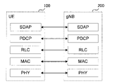
- FIG. 4 is a diagram showing the configuration of the protocol stack of the radio interface of the user plane that handles data.
- the user plane radio interface protocol includes a physical (PHY) layer, a MAC (Medium Access Control) layer, an RLC (Radio Link Control) layer, a PDCP (Packet Data Convergence Protocol) layer, and an SDAP (Service Data Adaptation Protocol) layer. layer.
- PHY physical
- MAC Medium Access Control
- RLC Radio Link Control
- PDCP Packet Data Convergence Protocol
- SDAP Service Data Adaptation Protocol
- the PHY layer performs encoding/decoding, modulation/demodulation, antenna mapping/demapping, and resource mapping/demapping. Data and control information are transmitted between the PHY layer of the UE 100 and the PHY layer of the gNB 200 via physical channels.
- the PHY layer of UE 100 receives downlink control information (DCI) transmitted from gNB 200 on a physical downlink control channel (PDCCH). Specifically, the UE 100 blind-decodes the PDCCH using the radio network temporary identifier (RNTI), and acquires the successfully decoded DCI as the DCI addressed to the UE 100 itself.
- the DCI transmitted from the base station 200 is added with CRC parity bits scrambled by the RNTI.
- the MAC layer performs data priority control, retransmission processing by hybrid ARQ (HARQ: Hybrid Automatic Repeat reQuest), random access procedures, and the like. Data and control information are transmitted between the MAC layer of the UE 100 and the MAC layer of the gNB 200 via transport channels.
- the MAC layer of gNB 200 includes a scheduler. The scheduler determines uplink and downlink transport formats (transport block size, modulation and coding scheme (MCS: Modulation and Coding Scheme)) and resource blocks to be allocated to UE 100 .
- MCS Modulation and Coding Scheme
- the RLC layer uses the functions of the MAC layer and PHY layer to transmit data to the RLC layer on the receiving side. Data and control information are transmitted between the RLC layer of the UE 100 and the RLC layer of the gNB 200 via logical channels.
- the PDCP layer performs header compression/decompression, encryption/decryption, etc.
- the SDAP layer maps IP flows, which are units for QoS (Quality of Service) control by the core network, and radio bearers, which are units for QoS control by AS (Access Stratum). Note that SDAP may not be present when the RAN is connected to the EPC.
- FIG. 5 is a diagram showing the protocol stack configuration of the radio interface of the control plane that handles signaling (control signals).
- the radio interface protocol stack of the control plane has an RRC (Radio Resource Control) layer and a NAS (Non-Access Stratum) layer instead of the SDAP layer shown in FIG.
- RRC Radio Resource Control
- NAS Non-Access Stratum
- RRC signaling for various settings is transmitted between the RRC layer of the UE 100 and the RRC layer of the gNB 200.
- the RRC layer controls logical, transport and physical channels according to establishment, re-establishment and release of radio bearers.
- RRC connection connection between the RRC of UE 100 and the RRC of gNB 200
- UE 100 is in the RRC connected state.
- RRC connection no connection between RRC of UE 100 and RRC of gNB 200
- UE 100 is in RRC idle state.
- UE 100 is in RRC inactive state.
- the NAS layer located above the RRC layer performs session management and mobility management.
- NAS signaling is transmitted between the NAS layer of the UE 100 and the NAS layer of the AMF 300a.
- the UE 100 has an application layer and the like in addition to the radio interface protocol.
- MBS is a service that enables data transmission from the NG-RAN 10 to the UE 100 via broadcast or multicast, that is, point-to-multipoint (PTM).
- MBS use cases include public safety communications, mission critical communications, V2X (Vehicle to Everything) communications, IPv4 or IPv6 multicast distribution, IPTV (Internet Protocol TeleVision), group communication, and software distribution. .
- a broadcast service provides service to all UEs 100 within a specific service area for applications that do not require highly reliable QoS.
- An MBS session used for broadcast services is called a broadcast session.
- a multicast service provides a service not to all UEs 100 but to a group of UEs 100 participating in the multicast service.
- An MBS session used for a multicast service is called a multicast session.
- a multicast service can provide the same content to a group of UEs 100 in a more wirelessly efficient manner than a broadcast service.
- FIG. 6 is a diagram showing an overview of MBS traffic distribution according to the embodiment.
- MBS traffic is distributed to multiple UEs from a single data source (application service provider).
- a 5G CN (5GC) 20 which is a 5G core network, receives MBS data from an application service provider, creates a copy of the MBS data (Replication), and distributes it.
- 5GC20 From the perspective of 5GC20, two multicast delivery methods are possible: 5GC Shared MBS Traffic delivery and 5GC Individual MBS Traffic delivery.
- the 5GC 20 receives single copies of MBS data packets and delivers individual copies of those MBS data packets to individual UEs 100 via per-UE 100 PDU sessions. Therefore, one PDU session per UE 100 needs to be associated with the multicast session.
- the 5GC 20 receives a single copy of MBS data packets and delivers the single copy of those MBS packets to the RAN nodes (ie gNB 200).
- a gNB 200 receives MBS data packets over an MBS tunnel connection and delivers them to one or more UEs 100 .
- PTP Point-to-Point
- PTM Point-to-Multipoint
- the gNB 200 delivers individual copies of MBS data packets to individual UEs 100 over the air.
- the gNB 200 delivers a single copy of MBS data packets to a group of UEs 100 over the air.
- the gNB 200 can dynamically determine which of PTM and PTP to use as the MBS data delivery method for one UE 100 .
- the PTP and PTM delivery methods are primarily concerned with the user plane.
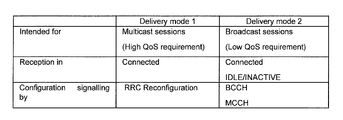
- FIG. 7 is a diagram showing distribution modes according to the embodiment.
- the first delivery mode (delivery mode 1) is a delivery mode that can be used by UE 100 in the RRC connected state, and is a delivery mode for high QoS requirements.
- the first delivery mode is used for multicast sessions among MBS sessions. However, the first delivery mode may be used for broadcast sessions.
- the first delivery mode may also be available for UEs 100 in RRC idle state or RRC inactive state.
- setting up MBS reception in the first delivery mode is done by UE-dedicated signaling.
- MBS reception settings in the first distribution mode are performed by an RRC Reconfiguration message (or RRC Release message), which is an RRC message unicast from the gNB 200 to the UE 100 .
- the MBS reception configuration includes MBS traffic channel configuration information (hereinafter referred to as "MTCH configuration information") regarding the configuration of MBS traffic channels that carry MBS data.
- MTCH configuration information includes MBS session information for an MBS session and scheduling information for MBS traffic channels corresponding to this MBS session.
- the MBS traffic channel scheduling information may include a discontinuous reception (DRX) configuration of the MBS traffic channel.
- DRX discontinuous reception
- the discontinuous reception setting includes a timer value (On Duration Timer) that defines an on duration (On Duration: reception period), a timer value (Inactivity Timer) that extends the on duration, a scheduling interval or DRX cycle (Scheduling Period, DRX Cycle), Scheduling or DRX cycle start subframe offset value (Start Offset, DRX Cycle Offset), ON period timer start delay slot value (Slot Offset), timer value defining maximum time until retransmission (Retransmission Timer), HARQ It may include any one or more parameters of timer value (HARQ RTT Timer) that defines the minimum interval to DL allocation for retransmission.
- HARQ RTT Timer timer value that defines the minimum interval to DL allocation for retransmission.
- the MBS traffic channel is a kind of logical channel and is sometimes called MTCH.
- the MBS traffic channel is mapped to a downlink shared channel (DL-SCH), which is a type of transport channel.
- DL-SCH downlink shared channel
- the second delivery mode (delivery mode 2) is a delivery mode that can be used not only by the UE 100 in the RRC connected state but also by the UE 100 in the RRC idle state or RRC inactive state, and is a delivery mode for low QoS requirements. .
- the second delivery mode is used for broadcast sessions among MBS sessions. However, the second delivery mode may also be applicable to multicast sessions.
- the setting for MBS reception in the second delivery mode is performed by broadcast signaling.
- the configuration of MBS reception in the second delivery mode is done via logical channels broadcasted from the gNB 200 to the UE 100, eg, Broadcast Control Channel (BCCH) and/or Multicast Control Channel (MCCH).
- the UE 100 can receive the BCCH and MCCH using, for example, a dedicated RNTI predefined in technical specifications.
- the RNTI for BCCH reception may be SI-RNTI
- the RNTI for MCCH reception may be MCCH-RNTI.
- the UE 100 may receive MBS data in the following three procedures. First, UE 100 receives MCCH configuration information from gNB 200 by SIB (MBS-SIB) transmitted on BCCH. Second, UE 100 receives MCCH from gNB 200 based on MCCH configuration information. MCCH carries MTCH configuration information. Third, the UE 100 receives MTCH (MBS data) based on MTCH setting information. In the following, MTCH configuration information and/or MCCH configuration information may be referred to as MBS configuration information.
- the UE 100 may receive MTCH using the group RNTI (G-RNTI) assigned by the gNB 200.
- G-RNTI corresponds to MTCH reception RNTI.
- An MBS session consists of a TMGI (Temporary Mobile Group Identity), a source-specific IP multicast address (consisting of a source unicast IP address such as an application function or application server, and an IP multicast address indicating a destination address), a session identifier, and G- Identified by at least one of the RNTIs.
- TMGI Temporal Mobile Group Identity
- source-specific IP multicast address Consisting of a source unicast IP address such as an application function or application server, and an IP multicast address indicating a destination address
- MBS session ID MBS session identifier
- TMGI, source-specific IP multicast address, session identifier, and G-RNTI are collectively referred to as MBS session information.
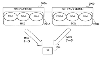
- FIG. 8 is a diagram illustrating a first operation scenario according to an embodiment;
- a first operation scenario is a DC scenario in which the UE 100 simultaneously communicates with two base stations (MN 200A and SN 200B).
- MN 200A may be an NR base station (gNB) or an LTE base station (eNB).
- MN (master node) 200A may be called a master base station.
- SN 200B may be an NR base station (gNB) or an LTE base station (eNB).
- the SN (secondary node) 200B may be called a secondary base station.
- UE 100 in the RRC connected state is assigned radio resources by the respective schedulers of MN 200A and SN 200B, which are mutually connected via a backhaul (network interface), and performs radio communication using the radio resources of MN 200A and SN 200B. I do.
- the network interface between MN 200A and SN 200 may be Xn interface or X2 interface.
- MN 200A and SN 200 communicate with each other via the network interface.
- MN 200A may have a control plane connection with the core network.
- the MN 200A provides the main radio resource for the UE 100.
- MN 200A manages MCG 201A.
- MCG 201A is a group of serving cells associated with MN 200A.
- MCG 201A has a PCell and optionally one or more SCells.
- SN 200B may not have a control plane connection with the core network.
- the SN 200B provides the UE 100 with additional radio resources.
- SN 200B manages SCG 201B.
- MCG 201A has a Primary Secondary Cell (PSCell) and optionally one or more SCells.
- PSCell Primary Secondary Cell
- MBS in the case of DC, it is assumed that UE 100 receives MBS from MCG 201A managed by MN 200A.
- MBS transmission from SCG 201B managed by SN 200B to UE 100 is performed.
- SN 200B supports multicast or broadcast transmission (PTM transmission) of MBS data.
- UE 100 receives MBS from either MN 200A (MCG 201A) or SN 200B (SCG 201B).
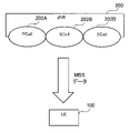
- FIG. 9 is a diagram showing a second operation scenario according to the embodiment.
- a second operation scenario is a scenario in which the UE 100 performs CA to simultaneously communicate with multiple serving cells of one base station (gNB 200).
- the plurality of serving cells has a PCell 202A and one or more SCells 202B.
- PCell 202A provides NAS mobility information to UE 100 when establishing, re-establishing, or handing over the RRC connection of UE 100, and provides security information when re-establishing the RRC connection of UE 100 or handing over.
- SCell 202B forms a set of serving cells with PCell 202A.
- MBS MBS transmission from PCell 202A.
- MBS transmission from SCell 202B to UE 100 is performed.
- the SCell 202B supports multicast or broadcast transmission of MBS data (PTM transmission).
- UE 100 receives MBS from either PCell 202A or SCell 202B.
- FIG. 10 is a diagram showing a first operation example according to the embodiment.
- the first operation example is an operation example related to the above-described first operation scenario (scenario in which DC is performed).
- step S11a the UE 100 starts DC as shown in FIG.
- MCG 201A MN 200A
- SCG 201B SCG 201B for UE 100 and activates SCG 201B.
- step S12a the UE 100 that performs DC communicates with the MCG 201A.
- UE 100 communicates MBS-related information regarding MBS reception from SCG 201B with MCG 201A.
- step S13a the UE 100 receives MBS from the SCG 201B.
- Step S13a may be performed before step S12a.
- the UE 100 that performs DC communicates MBS-related information regarding MBS reception from the SCG 201B with the MCG 201A. This enables the UE 100 to efficiently receive MBS from the SCG 201B under the control of the MCG 201A (MN 200A).
- FIG. 11 is a diagram showing a second operation example according to the embodiment.
- the second operation example is an operation example related to the above-described second operation scenario (scenario in which CA is performed).
- step S11b the UE 100 starts CA as shown in FIG.
- PCell 202A gNB 200
- SCell 202B for UE 100 and activates SCell 202B.
- step S12b the UE 100 that performs CA communicates with the PCell 202A.
- UE 100 communicates MBS-related information regarding MBS reception from SCell 202B with PCell 202A.
- step S13b the UE 100 receives MBS from the SCell 202B.
- Step S13b may be performed before step S12b.
- the UE 100 that performs CA communicates MBS-related information regarding MBS reception from the SCell 202B to the PCell 202A. This enables the UE 100 to efficiently receive MBS from the SCell 202B under the control of the PCell 202A.
- MCG 201A and PCell 202A play similar roles
- SCell 202B and SCell 202B play similar roles.
- MCG201A or PCell202A is described as MCG201A/PCell202A
- SCell202B or SCell202B is described as SCell202B/SCell202B.
- steps S11a and S11b are not distinguished, they are simply called step S11
- steps S12a and S12b are not distinguished, they are simply called step S12
- steps S13a and S13b are not distinguished, they are simply called step S13.
- Step S12 may be a step in which the UE 100 receives MBS-related information from the MCG 201A/PCell 202A.
- UE 100 receives MBS-related information from MCG 201A/PCell 202A from MCG 201A/PCell 202A by RRC Reconfiguration message, paging message, SIB (BCCH), MCCH, MAC control element (MAC CE), or downlink control information (DCI).
- SIB SIB
- MCCH MAC control element
- DCI downlink control information
- the MBS-related information received by UE 100 includes MBS session information indicating an MBS session provided by SCG 201B / SCell 202B, frequency-related information regarding the frequency provided by the MBS session, MBS setting information indicating setting of MBS reception, and SCG 201B. and cell identification information indicating /SCell 202B. This enables UE 100 to smoothly receive MBS from SCG 201B/SCell 202B.
- the MBS-related information received by the UE 100 from the MCG 201A/PCell 202A may be a session start notification indicating the start of the MBS session in the SCG 201B/SCell 202B. This enables UE 100 to start receiving MBS in SCG 201B/SCell 202B in accordance with the start of the MBS session in SCG 201B/SCell 202B.
- the MBS-related information received by the UE 100 from the MCG 201A/PCell 202A may be session change information (session change notification) indicating the change of the MBS session in the SCG 201B/SCell 202B, or session stop notification indicating the stop of the MBS session.
- the suspension of the MBS session may be signaled as session change information.
- the MBS-related information received by the UE 100 from the MCG 201A/PCell 202A may be MTCH setting information regarding the MTCH in the SCG 201B/SCell 202B.
- the MTCH configuration information transmitted by MCG 201A may be obtained from SCG 201B (SN 200B). That is, SN 200B managing SCG 201B may transmit MTCH configuration information to MN 200A managing MCG 201A using a network interface (such as Xn or X2).
- the MBS-related information received by the UE 100 from the MCG 201A/PCell 202A may be MCCH setting information regarding the MCCH in the SCG 201B/SCell 202B.
- the MCCH configuration information transmitted by MCG 201A may be obtained from SCG 201B (SN 200B). That is, SN 200B managing SCG 201B may transmit MCCH setting information to MN 200A managing MCG 201A using a network interface (such as Xn or X2).
- MTCH configuration information and/or MCCH configuration information may be referred to as MBS configuration information.
- the MBS-related information received by the UE 100 from the MCG 201A/PCell 202A may be notification information indicating that MBS setting information indicating MBS reception settings in the SCG 201B/SCell 202B is transmitted from the SCG 201B/SCell 202B. Thereby, UE100 becomes recognizable that the MBS setting information of SCG201B/SCell202B is not provided from MCG201A/PCell202A.
- Step S12 may be a step in which the UE 100 transmits MBS-related information to the MCG 201A/PCell 202A.
- the UE 100 may transmit MBS-related information to the MCG 201A/PCell 202A using an RRC message, MAC CE, PDCP Control PDU (Protocol Data Unit), or uplink control information (UCI).
- RRC message MAC CE
- PDCP Control PDU Protocol Data Unit
- UCI uplink control information
- the MBS-related information that UE100 transmits to MCG201A / PCell202A includes MBS session information indicating an MBS session that UE100 is receiving or is interested in receiving, frequency-related information about the frequency on which the MBS session is provided, and UE100 and priority information indicating which of MBS reception and unicast reception is prioritized. This enables MCG 201A/PCell 202A to grasp the interest of UE 100 in MBS.
- the MBS-related information that UE 100 transmits to MCG 201A/PCell 202A may be an MBS Interest Indication (MBS Interest Indication: MII) regarding an MBS session that UE 100 is receiving or interested in receiving.
- MII MBS Interest Indication
- MBS session information indicating an MBS session that UE 100 is receiving or is interested in receiving
- frequency-related information about the frequency on which the MBS session is provided, and which of MBS reception and unicast reception is prioritized by UE 100.
- priority information indicating whether to
- the UE 100 may send MII to the MCG 201A if the MCG 201A provides an MBS session that the UE 100 is receiving or interested in receiving.
- UE 100 when SCG 201B / SCell 202B provides an MBS session that UE 100 is receiving or is interested in receiving, MII indicating that SCG 201B / SCell 202B provides the MBS session to MCG 201A / PCell 202A. good too.
- the MBS-related information (eg, MII) received by MCG 201A (MN 200A) from UE 100 is preferably shared with SCG 201B (SN 200B). Therefore, MN 200A managing MCG 201A may transmit MBS-related information (eg, MII) received from UE 100 to SN 200B managing SCG 201B using a network interface (such as Xn or X2).
- MBS-related information eg, MII
- MBS-related information that UE 100 transmits to MCG 201A / PCell 202A is MBS reception indicating timing (hereinafter referred to as "MBS reception gap") to interrupt communication with MCG 201A / PCell 202A for UE 100 to receive MBS from SCG 201B / SCell 202B It may be gap information. This enables UE 100 to efficiently receive MBS from SCG 201B/SCell 202B using MBS reception gaps while maintaining connection with MCG 201A/PCell 202A.
- the MBS-related information that UE 100 transmits to MCG 201A/PCell 202A may be information for UE 100 to receive MBS data retransmission from SCG 201B/SCell 202B (or MCG 201A/PCell 202A).
- the information indicates packets successfully and/or unsuccessfully received by the PDCP layer, and may be, for example, a PDCP Status Report.
- the PDCP Status Report may include any one or more of FMC (First missing packet: sequence number information of the packet that failed to be received first) and Bitmap (bitmap information indicating success/failure of packet reception after FMC) good.
- FMC First missing packet: sequence number information of the packet that failed to be received first
- Bitmap bitmap information indicating success/failure of packet reception after FMC
- FIG. 12 is a diagram showing a third operation example according to the embodiment.
- the third operation example is an operation example in which the UE 100 monitors the physical downlink control channel (PDCCH) of the SCG 201B/SCell 202B in a DC or CA scenario.
- PDCCH physical downlink control channel
- step S21 the UE 100 starts DC or CA.
- UE 100 that receives MBS in SCG 201B/SCell 202B monitors PDCCH in SCG 201B/SCell 202B using RNTI for MBS reception in SCG 201B/SCell 202B.
- An RNTI for MBS reception is called an MBS reception RNTI.
- the MBS reception RNTI is at least one of an MTCH RNTI for receiving MTCH, an MCCH RNTI for receiving MCCH, and a change notification RNTI for receiving MCCH change notification, good too.
- the SCG 201B/SCell 202B are deactivated.
- UE 100 deactivates SCG 201B/SCell 202B in response to SCG 201B/SCell 202B receiving a deactivation instruction from MCG 201A/PCell 202A via MAC CE.
- step S24 the UE 100 continues monitoring the PDCCH in the SCG 201B/SCell 202B using the MBS reception RNTI even if the SCG 201B/SCell 202B is deactivated.
- FIG. 13 is a diagram showing a fourth operation example according to the embodiment.
- a fourth operation example is an operation example in which the UE 100 transmits MII in a DC scenario.
- step S31 the UE 100 starts DC.
- step S32 the UE 100 identifies, from among the MCG 201A and SCG 201B, the cell group (CG) that provides the MBS session that the UE 100 is receiving or is interested in receiving.
- CG cell group
- step S33 the UE 100 transmits MII regarding the MBS session to the cell group identified in step S32.
- MII can be transmitted to an appropriate CG.
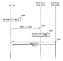
- FIG. 14 is a diagram showing a fifth operation example according to the embodiment.
- a fifth operation example is an operation example in which MN 200A and SN 200B communicate with each other in a DC scenario.
- step S41 the UE 100 starts DC.
- MN 200A communicates with SN 200B.
- MN 200A may obtain the MII for the MBS session that UE 100 is receiving or interested in receiving and may send the MII to SN 200B.
- MN 200A may receive the MII from SN 200B.
- Step S42 may be performed before step S41.
- MCG 201A MN 200A
- SCG 201B SN 200B
- MCG 201A MN 200A
- SCG 201B SN 200B
- FIG. 15 is a diagram showing a sixth operation example according to the embodiment.
- a sixth operation example is an operation example in which MN 200A and SN 200B communicate with each other in a DC scenario.
- step S51 the UE 100 starts DC.
- SN 200B communicates with MN 200A.
- SN 200B transmits to MN 200A MBS setting information indicating settings for UE 100 to receive MBS in SCG 201B.
- the SN 200B performs MBS transmission to the UE 100.
- MN 200A can perform efficient communication with UE 100 in consideration of the MBS setting information. For example, MN 200A performs scheduling or activation/deactivation control of SCG 201B/SCell 202B in consideration of MBS setting information of SN 200B.
- the MN 200A may transmit the MBS setting information of the SN 200B to the UE 100.
- MCG 201A may be read as MN 200A
- SCG 201B may be read as SN 200B
- PCell 202A may be read as a base station (gNB 200).
- FIG. 16 is a figure which shows 1st Example.
- DC or CA has been started, UE100 shall be waiting for the start of the MBS session to be provided from SCG201B / SCell202B.
- the MCG 201A/PCell 202A detects the start of the MBS session to be provided by the SCG 201B/SCell 202B.
- gNB 200 can grasp the MBS session start to be provided by SCell 202B.
- MCG 201A (MN 200A) may obtain session initiation information from AMF 300 (core network) and/or from SN 200B.
- the MCG 201A/PCell 202A notifies the UE 100 of the MBS session start of the SCG 201B/SCell 202B using an RRC Reconfiguration message, paging message, SIB, or MCCH.
- the notification includes at least one of the following information.
- MBS session information Information indicating the MBS session scheduled to be provided by the SCG 201B/SCell 202B, such as session ID, TMGI, source-specific IP multicast address, G-RNTI, and the like.
- frequency information indicating the frequency (carrier frequency) provided MBS session scheduled to be provided by SCG201B / SCell202B
- BWP information indicating the bandwidth portion (BWP) provided by the MBS session
- MBS At least one of CFR information indicating a Common Frequency Resource (CFR) in which the session is provided.
- CFR Common Frequency Resource
- - MBS setting information of SCG201B/SCell202B For example, it is at least one of MCCH setting information and MTCH setting information of SCG201B/SCell202B.
- SCG201B/SCell202B For example, it is a cell ID or a cell index of SCG201B/SCell202B.
- SCG 201B it may be the cell ID or cell index of the PSCell.
- the UE 100 starts receiving MBS in the SCG 201B/SCell 202B upon receiving the session start notification.
- the UE 100 may turn on a receiver (receiving circuit, RF circuit) for receiving MBS in the SCG 201B/SCell 202B. That is, the UE 100 may turn off the receiver for receiving MBS in the SCG 201B/SCell 202B until receiving the session start notification of the SCG 201B/SCell 202B from the MCG 201A/PCell 202A. Thereby, the power consumption of the UE 100 is reduced.
- a receiver receiving circuit, RF circuit
- UE 100 may start PDCCH monitoring for SCG 201B/SCell 202B using RNTI for MBS in response to reception of a session start notification from MCG 201A/PCell 202A to SCG 201B/SCell 202B while keeping the receiver in an ON state. .
- step S104 UE 100 receives MTCH (MBS data) from SCG 201B/SCell 202B based on the session start notification received from MCG 201A/PCell 202A.
- MTCH MMS data
- MCG 201A/PCell 202A notifies UE 100 of the MBS session start of SCG 201B/SCell 202B. Thereby, UE100 can efficiently perform MBS reception in SCG201B/SCell202B.
- the MCG 201A/PCell 202A may notify the UE 100 of session change or session stop of the SCG 201B/SCell 202B. This enables UE 100 to grasp the session change or session stop of SCG 201B/SCell 202B.
- Such session change notification or session stop notification may be sent in a similar manner as the session start notification described above and may contain the same information elements as the session start notification described above.
- the MCG 201A/PCell 202A may notify the UE 100 that the SCG 201B/SCell 202B MBS-SIB has been changed (or the SCG 201B/SCell 202B MBS-SIB value tag). This enables UE 100 to grasp the change of MBS-SIB of SCG 201B/SCell 202B.
- FIG. 17 is a diagram showing a second embodiment. Here, it is assumed that DC or CA has been started.
- the SCG 201B/SCell 202B shares its own MBS setting information with the MCG 201A/PCell 202A.
- SCG 201B sends its own MBS setup information to MCG 201A (MN 200A).
- SCG 201B may send its own MBS setting information to MCG 201A (MN 200A) triggered by a change in its own MBS setting or an inquiry from MN 200A.
- SCG 201B may request MCG 201A (MN 200A) to transmit the MBS setting information from MCG 201A (MN 200A). If the MCG 201A (MN 200A) accepts the request, it may send a response to that effect to the SCG 201B (SN 200B).
- the SCG 201B/SCell 202B may notify the UE 100 via MBS-SIB that the MCCH (MTCH setting information) of the SCG 201B/SCell 202B is transmitted from the MCG 201A/PCell 202A.
- SCG201B/SCell202B may transmit the MCCH setting information of MCG201A/PCell202A in MBS-SIB. Thereby, UE100 can receive MCCH of MCG201A/PCell202A smoothly.
- the MCCH configuration information includes at least one of MCCH-related settings, such as repetition period, offset, first subframe, duration, modification period, scheduling info (on-duration, DRX inactivity timer, scheduling period, start offset).
- the MCCH configuration information may include at least one of the frequency of the MCCH of the MCG201A/PCell202A, the ID of the cell that provides the MCCH of the MCG201A/PCell202A, the BWP information/CFR information of the MCCH of the MCG201A/PCell202A, and the MBS session information. .
- UE 100 may start monitoring the MCCH of MCG 201A/PCell 202A based on the MBS-SIB.
- the MCG 201A/PCell 202A may notify the UE 100 via MBS-SIB that the MCCH of the MCG 201A/PCell 202A contains the MBS setting information (MTCH setting information) of the SCG 201B/SCell 202B.
- MCG201A / PCell202A in MBS-SIB, SCG201B / SCell202B MBS provided frequency, SCG201B / SCell202B MBS provided cell ID, SCG201B / SCell202B MBS provided BWP / CFR information, out of the MBS session information At least one may be notified to the UE 100.
- the MCG 201A/PCell 202A transmits the MBS setting information (MTCH setting information) of the SCG 201B/SCell 202B on MCCH.
- the MBS configuration information includes, for example, information of each MTCH of SCG 201B/SCell 202B (eg, MBS session information, G-RNTI, MTCH scheduling info (DRX configuration)) and a neighboring cell list that provides the MBS session.
- the MBS configuration may include at least one of SCG 201B/SCell 202B MBS providing frequency, SCG 201B/SCell 202B MBS providing cell ID, SCG 201B/SCell 202B MBS providing BWP/CFR information.
- UE 100 acquires MCCH on MCG 201A/PCell 202A, and receives MTCH (MBS data) of SCG 201B/SCell 202B based on MBS setting information (MTCH setting information) acquired by MCCH (step S205).
- MBS data MBS setting information
- MCG201A / PCell202A by notifying the UE100 MBS configuration information (MTCH configuration information) of SCG201B / SCell202B, UE100 efficiently performing MBS reception in SCG201B / SCell202B can be done.
- MBS configuration information MBS configuration information
- UE 100 only needs to monitor MCCH for MCG 201A/PCell 202A, and there is no need to monitor MCCH for SCG 201B/SCell 202B, so power consumption of UE 100 can be reduced.
- FIG. 18 is a diagram showing a third embodiment. Here, it is assumed that DC or CA has been started.
- the MCG 201A/PCell 202A notifies the UE 100 via MBS-SIB (or MCCH) that the MBS setting information for the MBS session provided by the SCG 201B/SCell 202B will be transmitted from the SCG 201B/SCell 202B.
- MCG201A / PCell202A in MBS-SIB (or MCCH), may notify the MCCH configuration information of SCG201B / SCell202B to UE100.
- the UE 100 may receive MBS-SIB (MCCH configuration information) on the MCG 201A/PCell 202A.
- MBS-SIB MCCH configuration information
- UE100 when the MCCH setting information of SCG201B / SCell202B is acquired from MCG201A / PCell202A in step S301, it is not necessary to receive MBS-SIB on MCG201A / PCell202A.
- step S303 the UE 100 receives MCCH (MTCH setting information) on the MCG 201A/PCell 202A based on the MCCH setting information acquired in step S301 or S302.
- MCCH MTCH setting information
- the UE 100 receives MTCH (MBS data) on the SCG 201B/SCell 202B based on the MTCH setting information acquired at step S303.
- MTCH MMS data
- MCG 201A/PCell 202A notifies UE 100 that MBS setting information for SCG 201B/SCell 202B is transmitted from SCG 201B/SCell 202B. Thereby, UE100 can efficiently perform MBS reception in SCG201B/SCell202B.
- FIG. 19 is a diagram showing a fourth embodiment. Here, it is assumed that DC or CA has been started.
- the UE 100 is receiving or interested in receiving the MBS session provided by the SCG 201B/SCell 202B.
- the UE 100 transmits to the MCG 201A/PCell 202A an MII indicating that it is receiving or interested in receiving the MBS session provided by the SCG 201B/SCell 202B.
- MII is MBS session information, frequency/cell ID of SCG201B/SCell202B, whether to prioritize MBS session reception in SCG201B/SCell202B (for example, whether the same service can be received in MCG201A/PCell202A) information at least one of
- the MCG 201A/PCell 202A activate/deactivate the SCG 201B/SCell 202B based on the MII from the UE 100.
- MCG 201A/PCell 202A controls SCG 201B/SCell 202B cells serving MBS sessions that UE 100 is receiving or is interested in receiving not to deactivate or to activate.
- MCG201A/PCell202A may set up a new session or radio bearer for UE100 to receive MBS in MCG201A/PCell202A.
- MCG201A/PCell202A may perform handover control of UE100 based on MII from UE100.
- UE 100 transmits MII to MCG 201A/PCell 202A indicating that it is receiving or interested in receiving the MBS session provided by SCG 201B/SCell 202B.
- MCG201A/PCell202A becomes possible [ considering MBS interest of UE100 about SCG201B/SCell202B, and performing appropriate communication control.
- FIG. 20 is a diagram showing a fifth embodiment. Here, it is assumed that DC or CA has been started.
- the UE 100 receiving or interested in receiving the MBS session provided from the SCG 201B / SCell 202B determines the MBS reception gap (MBS reception gap pattern) for receiving MBS from the SCG 201B / SCell 202B. do.
- the MBS reception gap may be the timing at which MTCH is scheduled in SCG 201B/SCell 202B.
- the MBS reception gap may include switching time for RF switching (receiver frequency switching) in the UE 100 .
- the UE 100 transmits a message including reception gap information indicating the determined MBS reception gap to the MCG 201A/PCell 202A.
- the reception gap information may be information indicating the reception gap pattern by its start timing and bitmap pattern.
- the message including reception gap information may include cell ID and frequency information of SCG 201B/SCell 202B.
- the reception gap information may be information indicating an MBS reception gap that the UE 100 requests setting.
- the MCG 201A/PCell 202A that has received the message may set the MBS reception gap in the UE 100 based on the reception gap information, for example, using the RRC Reconfiguration message.
- the MCG 201A/PCell 202A perform scheduling control so as not to schedule the UE 100 in MBS reception gaps. Specifically, MCG 201A/PCell 202A controls not to perform unicast communication with UE 100 at the timing (MBS reception gap) at which UE 100 receives MBS from SCG 201B/SCell 202B.
- step S504 the UE 100 performs MBS reception from the SCG 201B/SCell 202B in MBS reception gaps. For example, UE 100 receives MBS data transmitted on MTCH from SCG 201B/SCell 202B in MBS reception gaps.
- UE 100 notifies MCG 201A/PCell 202A of MBS reception gaps (MBS reception gap patterns) for receiving MBS from SCG 201B/SCell 202B.
- MBS reception gap patterns MBS reception gap patterns
- SCG 201B/SCell 202B may notify MTCH configuration information (MTCH scheduling information) to MCG 201A/PCell 202A.
- MCG201A / PCell202A by notification from SCG201B / SCell202B, SCG201B / SCell202B to grasp the timing of MBS transmission, it is possible to control not to perform unicast communication with UE100 at the timing .
- UE 100 may transfer MTCH configuration information (MTCH scheduling information) obtained from SCG 201B / SCell 202B to MCG 201A / PCell 202A. good.
- MCG201A / PCell202A from the information transferred from UE100, grasps the timing when SCG201B / SCell202B performs MBS transmission, it is possible to control not to perform unicast communication with UE100 at the timing .
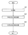
- FIG. 21 is a diagram showing the operation of the MAC entity of the UE 100 according to the sixth example.
- FIG. 21 shows a modified example of the MAC layer technical specification (TS38.321).
- the SCell 202B set in the UE 100 may be deactivated under the control of the PCell 202A.
- UE 100 does not monitor the PDCCH of deactivated SCell 202B.
- the UE 100 does not perform physical uplink control channel (PUCCH) transmission and random access channel (RACH) transmission to the deactivated SCell 202B.
- PUCCH physical uplink control channel
- RACH random access channel
- activation/deactivation of SCell 202B in general CA assumes unicast communication. If MBS supports CA, it is desirable to allow MBS reception independent of activation/deactivation of SCell 202B.
- the UE 100 cannot receive the MTCH because it does not monitor the PDCCH using the group RNTI (G-RNTI) for receiving the MTCH.
- G-RNTI group RNTI
- the G-RNTI corresponds to the RNTI for MTCH.
- UE 100 does not perform PUCCH transmission in SCell 202B at all, HARQ feedback in MBS reception cannot be performed to SCell 202B. Furthermore, if the UE 100 does not perform RACH transmission in the SCell 202B at all, it cannot perform an on-demand SI request to the SCell 202B and cannot request the SCell 202B to transmit MBS-SIB. .
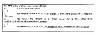
- the UE 100 performs the following operation for each configured SCell 202B (each configured SCell) when the SCell 202B is deactivated (if the SCell is deactivated). .
- the MAC entity of UE 100 does not transmit RACH on the SCell 202B, except for on-demand SI requests for MBS-SIBs of interest (not transmit on RACH on the SCell, except for on-demand SI request for MBS-SIB of interest). In other words, even if the SCell 202B is deactivated, the UE 100 is allowed to transmit RACH for that SCell 202B when making an on-demand SI request for the MBS-SIB of interest.
- the MAC entity of UE 100 does not monitor the PDCCH on the SCell 202B except for G-RNTI, MCCH-RNTI, and Notification-RNTI for MBS reception of interest (not monitor the PDCCH on the SCell, except for G-RNTI, MCCH-RNTI, Notification-RNTI for MBS reception of interest).
- MCCH-RNTI corresponds to MCCH RNTI
- Notification-RNTI corresponds to change notification RNTI.
- the UE 100 is allowed to monitor the PDCCH of that SCell 202B with the G-RNTI, MCCH-RNTI, and Notification-RNTI for MBS reception of interest even if the SCell 202B is deactivated. be.
- the MAC entity of the UE 100 does not transmit PUCCH on the SCell 202B, except for HARQ feedback for MBS reception (not transmit PUCCH on the SCell, except for HARQ feedback for MBS reception). In other words, even when the SCell 202B is deactivated, the UE 100 is allowed to transmit PUCCH to the SCell 202B when performing HARQ feedback for MBS reception.
- SCell 202B in the above operation is read as SCG 201B (or PSCell of SCG 201B).
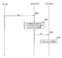
- FIG. 22 is a diagram showing the sixth embodiment. Here, operations related to PDCCH monitoring will be mainly described.
- the UE 100 is receiving or interested in receiving the MBS session provided by the SCG 201B/SCell 202B.
- step S602 UE 100 monitors PDCCH (DCI) of SCG 201B/SCell 202B using G-RNTI, MCCH-RNTI, and Notification RNTI. UE 100 may also monitor SI-RNTI for MBS-SIB reception.
- DCI PDCCH
- step S603 the MCG 201A/PCell 202A deactivates the SCG 201B/SCell 202B by, for example, transmitting a deactivation instruction for the SCG 201B/SCell 202B to the UE 100 and the SCG 201B/SCell 202B.
- step S604 UE 100 continues PDCCH monitoring using G-RNTI, MCCH-RNTI, Notification RNTI, and SI-RNTI even if SCG 201B/SCell 202B is deactivated, and receives DCI from SCG 201B/SCell 202B .
- step S605 UE 100 receives MTCH (MBS data) from SCG 201B/SCell 202B based on DCI received by PDCCH monitoring.
- MTCH MMS data
- UE 100 continues PDCCH monitoring using G-RNTI, MCCH-RNTI, Notification RNTI, and SI-RNTI even if SCG 201B/SCell 202B are deactivated. This makes it possible to improve MBS reception continuity.
- FIG. 23 is a diagram showing a seventh embodiment. Here, the operation in the case of DC will be described.
- step S701 the UE 100 (RRC layer) generates MII. Assume that the MII generated by the UE 100 is an RRC message.
- step S702 the UE 100 (RRC layer) determines whether the MBS session of interest is provided by the MCG 201A or the SCG 201B.
- the UE 100 transmits MII to the CG provided with the MBS session of interest.
- the RRC layer of UE 100 passes MII to the MAC entity corresponding to the CG.
- the RRC layer of the UE 100 transmits MII using the signaling radio bearer (SRB) corresponding to the CG.
- SRB signaling radio bearer
- the RRC layer of UE 100 transmits MII to MCG 201A using SRB1 in step S703.
- SRB1 is an SRB established between UE 100 and MCG 201A (MN 200A).
- the RRC layer of UE 100 transmits MII to SCG 201B by SRB3 in step S704.
- SRB3 is an SRB established between UE 100 and SCG 201B (SN 200B).
- UE 100 is for both CGs may transmit MII.
- the UE 100 may transmit (a copy of) the same message to both CGs.
- the UE 100 may transmit separate messages (TMGI#1-related only/TMGI#2-related only, etc.) to the corresponding CGs.
- the UE 100 transmits MII to the CG provided with the MBS session of interest. For example, UE 100 sends MII to SCG 201B over SRB 3 when the MBS session of interest is served by SCG 201B. This allows the MII to be transmitted to an appropriate destination.
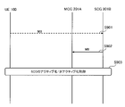
- FIG. 24 is a diagram showing an eighth embodiment. Here, the operation in the case of DC will be described.
- the MCG 201A acquires the MII (MBS Interest Information) of the UE 100.
- MCG 201A receives MII from UE 100 or acquires MII from AMF 300 (core network).
- MCG 201A recognizes that the MBS session of interest for UE 100 is provided by SCG 201B (SN 200B).
- the MBS session information provided by SN 200B may be provided by AMF 300 (core network) and/or SN 200B.
- Information about the MBS session may be set in OAM (Operation, Administration and Maintenance).
- MCG 201A may identify SCG 201B (SN 200B) from the information on the frequency on which the MBS session is provided.
- the MCG 201A transmits the MII of the UE 100 to the SCG 201B (SN 200B).
- the MII may be included in the Xn message (inter-base station communication message) transmitted from MN 200A to SN 200B.
- the Xn message may be an SN Addition message used when DC is started and/or an SN Modification message used to change the settings of SCG 201B (SN 200B) after DC is started.
- the MII may be included as UE context within these messages.
- the Xn messages may be X2 messages.
- MII includes at least one of MBS session information (session ID, TMGI, G-RNTI, etc.), MBS frequency information, BWP (CFR) information, and priority information between MBS and unicast.
- the MII or Xn message may include at least one of MB-UPF (Multicast Broadcast User Plane Function) related MBS tunnel identifiers of the core network and UE identifiers (such as XnAP UE-ID).
- MB-UPF Multicast Broadcast User Plane Function
- step S804 SCG 201B (SN 200B) schedules MBS transmission and unicast communication based on the Xn message (MII) received from MCG 201A (MN 200A). For example, the SCG 201B (SN 200B) performs operations such as allocating unicast communication resources to the UE 100 by scheduling, avoiding multicast. SCG 201B (SN 200B) may transmit MBS configuration information to UE 100 via the RRC Reconfiguration message or MCG 201A based on the Xn message (MII).
- MII Xn message
- MCG 201A (MN 200A) transmits the MII of UE 100 to SCG 201B (SN 200B). This enables the SCG 201B (SN 200B) to appropriately perform communication control (scheduling, etc.) of the UE 100 in consideration of the MBS interest of the UE 100.
- FIG. 25 is a diagram showing a ninth embodiment. Here, the operation in the case of DC will be described.
- the SCG 201B acquires the MII (MBS Interest Information) of the UE 100.
- MII MMS Interest Information
- SCG201B receives MII from UE100, or acquires MII from AMF300 (core network).
- the SCG 201B transmits the MII of the UE 100 to the MCG 201A (MN 200A).
- SCG 201B (SN 200B) may transmit MII to MCG 201A (MN 200A) triggered by notification of MII from UE 100 or an inquiry from MN 200A.
- the MII may be included in the Xn message (inter-base station communication message) transmitted from SN 200B to MN 200A.
- the Xn message may be a gNB Configuration Update message regarding the configuration change of the SN 200B, a response message to the SN Addition message, and/or a response message to the SN Modification message.
- the MII may be included as UE context within these messages.
- Information contained in the MII and Xn messages is the same as in the eighth embodiment described above. Note that the Xn message may be the X2 message.
- MCG 201A performs activation/deactivation control of SCG 201B/SCell 202B based on the Xn message (MII) received from SCG 201B (SN 200B).
- MCG 201A may set a new session or radio bearer for UE 100 to receive MBS in MCG 201A/PCell 202A based on the Xn message (MII).
- the DC may be multi-connectivity (MC).
- MC the UE 100 communicates with two or more base stations at the same time.
- MN master base station
- SN secondary base stations
- the gNB 200 (MN 200A, SN 200B) is configured with a CU and a DU (that is, the function is divided) and both units are connected by an F1 interface
- the CU that acquires the MII of the UE 100 may inform the DU of the MII over the F1 interface. This enables the scheduler provided in the DU to perform scheduling considering the MII.
- Each operation flow described above is not limited to being implemented independently, but can be implemented by combining two or more operation flows. For example, some steps of one operation flow may be added to another operation flow, or some steps of one operation flow may be replaced with some steps of another operation flow.
- the base station may be an NR base station (gNB) or a 6G base station.
- the base station may be a relay node such as an IAB (Integrated Access and Backhaul) node.
- IAB Integrated Access and Backhaul
- a base station may be a DU of an IAB node.
- the user equipment may be an MT (Mobile Termination) of an IAB node.
- a program that causes a computer to execute each process performed by the UE 100 or the gNB 200 may be provided.
- the program may be recorded on a computer readable medium.
- a computer readable medium allows the installation of the program on the computer.
- the computer-readable medium on which the program is recorded may be a non-transitory recording medium.
- the non-transitory recording medium is not particularly limited, but may be, for example, a recording medium such as CD-ROM or DVD-ROM.
- a circuit that executes each process performed by the UE 100 or gNB 200 may be integrated, and at least part of the UE 100 or gNB 200 may be configured as a semiconductor integrated circuit (chipset, SoC: System on a chip).
- the terms “based on” and “depending on,” unless expressly stated otherwise, “based only on.” does not mean The phrase “based on” means both “based only on” and “based at least in part on.” Similarly, the phrase “depending on” means both “only depending on” and “at least partially depending on.” Also, “obtain/acquire” may mean obtaining information among stored information, or it may mean obtaining information among information received from other nodes. or it may mean obtaining the information by generating the information.
- the terms “include,” “comprise,” and variations thereof are not meant to include only the recited items, and may include only the recited items or in addition to the recited items. Means that it may contain further items.
- references to elements using the "first,” “second,” etc. designations used in this disclosure do not generally limit the quantity or order of those elements. These designations may be used herein as a convenient method of distinguishing between two or more elements. Thus, references to first and second elements do not imply that only two elements may be employed therein, or that the first element must precede the second element in any way.
- references to first and second elements do not imply that only two elements may be employed therein, or that the first element must precede the second element in any way.
- UE 110 Reception unit 120: Transmission unit 130: Control unit 200: gNB 200A: MN 200B: SN 201A: MCG 201B: SCG 202A: PCell 202B: SCell 210: transmitter 220: receiver 230: controller 240: backhaul communication unit 300: AMF/UPF
Landscapes
- Engineering & Computer Science (AREA)
- Computer Networks & Wireless Communication (AREA)
- Signal Processing (AREA)
- Multimedia (AREA)
- Mobile Radio Communication Systems (AREA)
Abstract
Description
図1は、実施形態に係る移動通信システムの構成を示す図である。移動通信システム1は、3GPP規格の第5世代システム(5GS:5th Generation System)に準拠する。以下において、5GSを例に挙げて説明するが、移動通信システムにはLTE(Long Term Evolution)システムが少なくとも部分的に適用されてもよい。移動通信システムには第6世代(6G)システムが少なくとも部分的に適用されてもよい。
実施形態に係るMBSの概要について説明する。MBSは、NG-RAN10からUE100に対してブロードキャスト又はマルチキャスト、すなわち、1対多(PTM:Point To Multipoint)でのデータ送信を可能とするサービスである。MBSのユースケース(サービス種別)としては、公安通信、ミッションクリティカル通信、V2X(Vehicle to Everything)通信、IPv4又はIPv6マルチキャスト配信、IPTV(Internet Protocol TeleVision)、グループ通信、及びソフトウェア配信等が想定される。
図8は、実施形態に係る第1動作シナリオを示す図である。第1動作シナリオは、UE100が2つの基地局(MN200A及びSN200B)と同時に通信するDCを行うシナリオである。MN200AはNR基地局(gNB)又はLTE基地局(eNB)であってもよい。MN(マスタノード)200Aはマスタ基地局と呼ばれてもよい。SN200BはNR基地局(gNB)又はLTE基地局(eNB)であってもよい。SN(セカンダリノード)200Bはセカンダリ基地局と呼ばれてもよい。
次に、上述の実施形態を前提として、第1実施例乃至第9実施例について説明する。これらの実施例は、別個独立して実施する場合に限らず、2以上の実施例を組み合わせて実施してもよい。また、以下の各実施例の動作フローにおいて、必ずしもすべてのステップを実行する必要は無く、一部のステップのみを実行してもよい。また、以下の各実施例の動作フローにおいて、ステップの順番を変更してもよい。以下の実施例において、MCG201AをMN200Aと読み替え、SCG201BをSN200Bと読み替え、PCell202Aを基地局(gNB200)と読み替えてもよい。
図16は、第1実施例を示す図である。ここでは、DC又はCAが開始されており、UE100がSCG201B/SCell202Bから提供予定のMBSセッションの開始を待っているものとする。
SCG201B/SCell202Bが提供予定のMBSセッションを示す情報であって、例えば、セッションID、TMGI、ソーススペシフィックIPマルチキャストアドレス、G-RNTIなどである。
例えば、SCG201B/SCell202Bが提供予定のMBSセッションが提供される周波数(キャリア周波数)を示す周波数情報、当該MBSセッションが提供される帯域幅部分(BWP)を示すBWP情報、及び当該MBSセッションが提供されるCFR(Common Frequency Resource)を示すCFR情報のうち少なくとも1つである。
例えば、SCG201B/SCell202BのMCCH設定情報及びMTCH設定情報のうち少なくとも1つである。
例えば、SCG201B/SCell202BのセルID又はセルインデックスである。SCG201Bについては、PSCellのセルID又はセルインデックスであってもよい。
図17は、第2実施例を示す図である。ここでは、DC又はCAが開始されているものとする。
図18は、第3実施例を示す図である。ここでは、DC又はCAが開始されているものとする。
図19は、第4実施例を示す図である。ここでは、DC又はCAが開始されているものとする。
図20は、第5実施例を示す図である。ここでは、DC又はCAが開始されているものとする。
図21は、第6実施例に係るUE100のMACエンティティ(MAC entity)の動作を示す図である。図21は、MACレイヤの技術仕様(TS38.321)の変更例を示している。
図23は、第7実施例を示す図である。ここでは、DCの場合の動作について説明する。
図24は、第8実施例を示す図である。ここでは、DCの場合の動作について説明する。
図25は、第9実施例を示す図である。ここでは、DCの場合の動作について説明する。
上述の実施形態及び実施例において、DCは、マルチコネクティビティ(MC)であってもよい。MCにおいて、UE100は2つもしくは3つ以上の基地局と同時に通信を行う。例えば、1つのマスタ基地局(MN)と2つのセカンダリ基地局(SN)と、同時に3つの基地局との通信を行う。
10 :NG-RAN
20 :5GC
100 :UE
110 :受信部
120 :送信部
130 :制御部
200 :gNB
200A :MN
200B :SN
201A :MCG
201B :SCG
202A :PCell
202B :SCell
210 :送信部
220 :受信部
230 :制御部
240 :バックホール通信部
300 :AMF/UPF
Claims (23)
- マルチキャスト・ブロードキャストサービス(MBS)をサポートする移動通信システムで用いる通信方法であって、
デュアルコネクティビティ(DC)又はキャリアアグリゲーション(CA)を行うユーザ装置が、前記DCにおけるマスタセルグループ又は前記CAにおけるプライマリセルと通信することと、
前記ユーザ装置が、前記DCにおけるセカンダリセルグループ又は前記CAにおけるセカンダリセルからのMBS受信を行うことと、を有し、
前記通信することは、前記セカンダリセルグループ又は前記セカンダリセルからの前記MBS受信に関するMBS関連情報を前記マスタセルグループ又は前記プライマリセルと通信することを含む
通信方法。 - 前記MBS関連情報を通信することは、前記ユーザ装置が前記MBS関連情報を前記マスタセルグループ又は前記プライマリセルから受信することを含む
請求項1に記載の通信方法。 - 前記ユーザ装置は、前記マスタセルグループ又は前記プライマリセルから、無線リソース制御(RRC)Reconfigurationメッセージ、ページングメッセージ、システム情報ブロック(SIB)、又はマルチキャスト制御チャネル(MCCH)により前記MBS関連情報を受信する
請求項2に記載の通信方法。 - 前記ユーザ装置が受信する前記MBS関連情報は、前記セカンダリセルグループ又は前記セカンダリセルが提供するMBSセッションを示すMBSセッション情報と、前記MBSセッションが提供される周波数に関する周波数関連情報と、前記MBS受信の設定を示すMBS設定情報と、前記セカンダリセルグループ又は前記セカンダリセルを示すセル識別情報と、のうち少なくとも1つを含む
請求項2又は3に記載の通信方法。 - 前記ユーザ装置が受信する前記MBS関連情報は、前記セカンダリセルグループ又は前記セカンダリセルにおけるMBSセッションの開始を示すセッション開始通知である
請求項2又は3に記載の通信方法。 - 前記ユーザ装置が受信する前記MBS関連情報は、前記セカンダリセルグループ又は前記セカンダリセルにおけるマルチキャストトラフィックチャネル(MTCH)に関するMTCH設定情報である
請求項2又は3に記載の通信方法。 - 前記セカンダリセルグループを管理するセカンダリノードが、前記マスタセルグループを管理するマスタノードに対して前記MTCH設定情報を送信することをさらに有する
請求項6に記載の通信方法。 - 前記ユーザ装置が受信する前記MBS関連情報は、前記セカンダリセルグループ又は前記セカンダリセルにおける前記MBS受信の設定を示すMBS設定情報が前記セカンダリセルグループ又は前記セカンダリセルから送信されることを示す通知情報である
請求項2又は3に記載の通信方法。 - 前記MBS関連情報を通信することは、前記ユーザ装置が前記MBS関連情報を前記マスタセルグループ又は前記プライマリセルに送信することを含む
請求項1に記載の通信方法。 - 前記ユーザ装置が送信する前記MBS関連情報は、前記ユーザ装置が受信している又は受信に興味を持つMBSセッションを示すMBSセッション情報と、前記MBSセッションが提供される周波数に関する周波数関連情報と、前記ユーザ装置がMBS受信及びユニキャスト受信のどちらを優先するかを示す優先情報と、のうち少なくとも1つを含む
請求項9に記載の通信方法。 - 前記ユーザ装置が送信する前記MBS関連情報は、前記ユーザ装置が受信している又は受信に興味を持つMBSセッションに関するMBS興味通知である
請求項9に記載の通信方法。 - 前記ユーザ装置は、前記ユーザ装置が受信している又は受信に興味を持つMBSセッションを前記マスタセルグループが提供する場合、前記MBS興味通知を前記マスタセルグループに送信する
請求項11に記載の通信方法。 - 前記ユーザ装置は、前記ユーザ装置が受信している又は受信に興味を持つMBSセッションを前記セカンダリセルグループ又は前記セカンダリセルが提供する場合、当該MBSセッションを前記セカンダリセルグループ又は前記セカンダリセルが提供することを示す前記MBS興味通知を前記マスタセルグループ又は前記プライマリセルに送信する
請求項11に記載の通信方法。 - 前記マスタセルグループを管理するマスタノードが、前記セカンダリセルグループを管理するセカンダリノードに対して前記MBS興味通知を送信することをさらに有する
請求項12又は13に記載の通信方法。 - 前記ユーザ装置が送信する前記MBS関連情報は、前記ユーザ装置が前記セカンダリセルグループ又は前記セカンダリセルから前記MBS受信を行うために前記マスタセルグループ又は前記プライマリセルとの通信を中断するタイミングを示すMBS受信ギャップ情報である
請求項9に記載の通信方法。 - マルチキャスト・ブロードキャストサービス(MBS)をサポートする移動通信システムで用いる通信方法であって、
ユーザ装置が、デュアルコネクティビティ(DC)又はキャリアアグリゲーション(CA)を行うことと、
前記ユーザ装置が、前記DCにおけるセカンダリセルグループ又は前記CAにおけるセカンダリセルでMBS受信を行うための無線ネットワーク一時識別子(RNTI)を用いて、前記セカンダリセルグループ又は前記セカンダリセルにおける物理下りリンク制御チャネル(PDCCH)を監視することと、
前記ユーザ装置が、前記セカンダリセルグループ又は前記セカンダリセルが非アクティブ化されても、前記RNTIを用いた前記PDCCHの監視を継続することと、を有する
通信方法。 - 前記RNTIは、マルチキャストトラフィックチャネル(MTCH)を受信するためのMTCH用RNTIと、マルチキャスト制御チャネル(MCCH)を受信するためのMCCH用RNTIと、MCCH変更通知を受信するための変更通知用RNTIと、のうち少なくとも1つである
請求項16に記載の通信方法。 - マルチキャスト・ブロードキャストサービス(MBS)をサポートする移動通信システムで用いる通信方法であって、
デュアルコネクティビティ(DC)を行うユーザ装置が、前記ユーザ装置が受信している又は受信に興味を持つMBSセッションを提供するセルグループをマスタセルグループ及びセカンダリセルグループの中から特定することと、
前記ユーザ装置が、前記特定したセルグループに対して、前記MBSセッションに関するMBS興味通知を送信することと、を有する
通信方法。 - マルチキャスト・ブロードキャストサービス(MBS)をサポートする移動通信システムで用いる通信方法であって、
ユーザ装置が行うデュアルコネクティビティ(DC)におけるマスタセルグループを管理するマスタノードが、前記DCにおけるセカンダリセルグループを管理するセカンダリノードと通信することと、
前記マスタセルグループ又は前記セカンダリセルグループから前記ユーザ装置に対するMBS送信を行うことと、を有し、
前記通信することは、前記ユーザ装置が受信している又は受信に興味を持つMBSセッションに関するMBS興味通知を前記セカンダリノードと通信することを含む
通信方法。 - 前記MBS興味通知を通信することは、前記マスタノードが前記MBS興味通知を前記セカンダリノードに送信することを含む
請求項19に記載の通信方法。 - 前記MBS興味通知を通信することは、前記マスタノードが前記MBS興味通知を前記セカンダリノードから受信することを含む
請求項19に記載の通信方法。 - 前記MBS興味通知は、前記ユーザ装置が受信している又は受信に興味を持つMBSセッションを示すMBSセッション情報と、前記MBSセッションが提供される周波数に関する周波数関連情報と、前記ユーザ装置がMBS受信及びユニキャスト受信のどちらを優先するかを示す優先情報と、のうち少なくとも1つを含む
請求項19乃至21のいずれか1項に記載の通信方法。 - マルチキャスト・ブロードキャストサービス(MBS)をサポートする移動通信システムで用いる通信方法であって、
ユーザ装置とのデュアルコネクティビティ(DC)におけるセカンダリセルグループを管理するセカンダリノードが、前記DCにおけるマスタセルグループを管理するマスタノードと通信することと、
前記セカンダリノードが、前記ユーザ装置に対するMBS送信を行うことと、を有し、
前記通信することは、前記セカンダリセルグループにおいて前記ユーザ装置がMBS受信を行うための設定を示すMBS設定情報を前記セカンダリノードから前記マスタノードに送信することを含む
通信方法。
Priority Applications (5)
| Application Number | Priority Date | Filing Date | Title |
|---|---|---|---|
| CN202280061374.7A CN117941384A (zh) | 2021-07-19 | 2022-07-19 | 通信方法 |
| EP22845921.0A EP4358550A4 (en) | 2021-07-19 | 2022-07-19 | COMMUNICATION PROCESS |
| JP2023536760A JP7537026B2 (ja) | 2021-07-19 | 2022-07-19 | 通信方法、ユーザ装置、ネットワーク装置、移動通信システム、プログラム及びチップセット |
| US18/416,711 US20240237143A1 (en) | 2021-07-19 | 2024-01-18 | Communication method |
| JP2024130922A JP7788505B2 (ja) | 2021-07-19 | 2024-08-07 | 通信方法、ユーザ装置、ネットワーク装置、移動通信システム、プログラム及びチップセット |
Applications Claiming Priority (2)
| Application Number | Priority Date | Filing Date | Title |
|---|---|---|---|
| JP2021119144 | 2021-07-19 | ||
| JP2021-119144 | 2021-07-19 |
Related Child Applications (1)
| Application Number | Title | Priority Date | Filing Date |
|---|---|---|---|
| US18/416,711 Continuation US20240237143A1 (en) | 2021-07-19 | 2024-01-18 | Communication method |
Publications (1)
| Publication Number | Publication Date |
|---|---|
| WO2023002988A1 true WO2023002988A1 (ja) | 2023-01-26 |
Family
ID=84980046
Family Applications (1)
| Application Number | Title | Priority Date | Filing Date |
|---|---|---|---|
| PCT/JP2022/028079 Ceased WO2023002988A1 (ja) | 2021-07-19 | 2022-07-19 | 通信方法 |
Country Status (5)
| Country | Link |
|---|---|
| US (1) | US20240237143A1 (ja) |
| EP (1) | EP4358550A4 (ja) |
| JP (2) | JP7537026B2 (ja) |
| CN (1) | CN117941384A (ja) |
| WO (1) | WO2023002988A1 (ja) |
Families Citing this family (1)
| Publication number | Priority date | Publication date | Assignee | Title |
|---|---|---|---|---|
| WO2024000293A1 (en) * | 2022-06-29 | 2024-01-04 | Mediatek Singapore Pte. Ltd. | Methods and apparatus of multicast broadcast services transmission and reception on scell or non-serving cell |
Citations (1)
| Publication number | Priority date | Publication date | Assignee | Title |
|---|---|---|---|---|
| JP2021119144A (ja) | 2015-07-02 | 2021-08-12 | エフ・ホフマン−ラ・ロシュ・アクチェンゲゼルシャフト | ベンゾオキサゼピンオキサゾリジノン化合物及び使用方法 |
Family Cites Families (4)
| Publication number | Priority date | Publication date | Assignee | Title |
|---|---|---|---|---|
| WO2015141842A1 (ja) * | 2014-03-20 | 2015-09-24 | 京セラ株式会社 | 通信制御方法及びユーザ端末 |
| WO2015199491A1 (ko) * | 2014-06-26 | 2015-12-30 | 엘지전자 주식회사 | 브로드캐스트 멀티캐스트 서비스를 위한 제어 정보의 송수신 방법 및 이를 위한 장치 |
| CN109155901B (zh) * | 2016-05-06 | 2020-12-18 | 华为技术有限公司 | 多播业务接收方法、多播业务发送方法、装置及系统 |
| WO2018032469A1 (en) * | 2016-08-18 | 2018-02-22 | Qualcomm Incorporated | Techniques and apparatuses for sc-ptm configuration in handover signaling for service continuity |
-
2022
- 2022-07-19 WO PCT/JP2022/028079 patent/WO2023002988A1/ja not_active Ceased
- 2022-07-19 CN CN202280061374.7A patent/CN117941384A/zh active Pending
- 2022-07-19 JP JP2023536760A patent/JP7537026B2/ja active Active
- 2022-07-19 EP EP22845921.0A patent/EP4358550A4/en active Pending
-
2024
- 2024-01-18 US US18/416,711 patent/US20240237143A1/en active Pending
- 2024-08-07 JP JP2024130922A patent/JP7788505B2/ja active Active
Patent Citations (1)
| Publication number | Priority date | Publication date | Assignee | Title |
|---|---|---|---|---|
| JP2021119144A (ja) | 2015-07-02 | 2021-08-12 | エフ・ホフマン−ラ・ロシュ・アクチェンゲゼルシャフト | ベンゾオキサゼピンオキサゾリジノン化合物及び使用方法 |
Non-Patent Citations (4)
| Title |
|---|
| "Discussion on MBS enhancement", 3GPP CONTRIBUTION: RWS-210126 |
| NOKIA, NOKIA SHANGHAI BELL: "Miscellaneous Aspects of MBS", 3GPP DRAFT; R2-2100371, 3RD GENERATION PARTNERSHIP PROJECT (3GPP), MOBILE COMPETENCE CENTRE ; 650, ROUTE DES LUCIOLES ; F-06921 SOPHIA-ANTIPOLIS CEDEX ; FRANCE, vol. RAN WG2, no. Electronic; 20210125 - 20210205, 15 January 2021 (2021-01-15), Mobile Competence Centre ; 650, route des Lucioles ; F-06921 Sophia-Antipolis Cedex ; France , XP051973557 * |
| See also references of EP4358550A4 |
| ZTE: "Discussion on the NG-RAN architecture enhancement for MBS", 3GPP DRAFT; R3-204648, 3RD GENERATION PARTNERSHIP PROJECT (3GPP), MOBILE COMPETENCE CENTRE ; 650, ROUTE DES LUCIOLES ; F-06921 SOPHIA-ANTIPOLIS CEDEX ; FRANCE, vol. RAN WG3, no. Online; 20200817 - 20200828, 6 August 2020 (2020-08-06), Mobile Competence Centre ; 650, route des Lucioles ; F-06921 Sophia-Antipolis Cedex ; France , XP051911221 * |
Also Published As
| Publication number | Publication date |
|---|---|
| CN117941384A (zh) | 2024-04-26 |
| JP7537026B2 (ja) | 2024-08-20 |
| EP4358550A1 (en) | 2024-04-24 |
| JP2024160309A (ja) | 2024-11-13 |
| JP7788505B2 (ja) | 2025-12-18 |
| JPWO2023002988A1 (ja) | 2023-01-26 |
| US20240237143A1 (en) | 2024-07-11 |
| EP4358550A4 (en) | 2024-10-16 |
Similar Documents
| Publication | Publication Date | Title |
|---|---|---|
| JP7307284B2 (ja) | 通信制御方法 | |
| US20240080939A1 (en) | Communication control method and user equipment | |
| JP7837447B2 (ja) | 通信制御方法、ユーザ装置、チップセット、プログラム及び移動通信システム | |
| US12543022B2 (en) | Communication control method, base station, and user equipment | |
| JP7734238B2 (ja) | 通信制御方法 | |
| WO2022153990A1 (ja) | 通信制御方法及びユーザ装置 | |
| JP7829651B2 (ja) | 通信方法、ネットワークノード、ユーザ装置、チップセット、プログラム、及び移動通信システム | |
| JP7688203B2 (ja) | 通信制御方法、基地局、コアネットワーク装置及びシステム | |
| JP2023082184A (ja) | 通信制御方法、基地局、ユーザ装置及びプロセッサ | |
| WO2023286784A1 (ja) | 通信制御方法、基地局、及びユーザ装置 | |
| JP2024123238A (ja) | 通信制御方法、ユーザ装置、プロセッサ、プログラム及び移動通信システム | |
| WO2022239691A1 (ja) | 通信制御方法 | |
| JP7738072B2 (ja) | 通信方法、ユーザ装置 | |
| JP7788505B2 (ja) | 通信方法、ユーザ装置、ネットワーク装置、移動通信システム、プログラム及びチップセット | |
| JP2026010095A (ja) | 通信制御方法、ユーザ装置、プロセッサ、プログラム、及び移動通信システム | |
| US20240298381A1 (en) | Communication method | |
| JP7425259B2 (ja) | 通信制御方法及び基地局 | |
| JP2024083465A (ja) | 通信方法、ユーザ装置、プログラム、及びプロセッサ | |
| WO2023063374A1 (ja) | 通信方法及びユーザ装置 | |
| WO2024034564A1 (ja) | 通信方法、集約ユニット、及び分散ユニット | |
| WO2022085644A1 (ja) | 通信制御方法 |
Legal Events
| Date | Code | Title | Description |
|---|---|---|---|
| 121 | Ep: the epo has been informed by wipo that ep was designated in this application |
Ref document number: 22845921 Country of ref document: EP Kind code of ref document: A1 |
|
| WWE | Wipo information: entry into national phase |
Ref document number: 2022845921 Country of ref document: EP Ref document number: 2023536760 Country of ref document: JP |
|
| ENP | Entry into the national phase |
Ref document number: 2022845921 Country of ref document: EP Effective date: 20240119 |
|
| NENP | Non-entry into the national phase |
Ref country code: DE |
|
| WWE | Wipo information: entry into national phase |
Ref document number: 202280061374.7 Country of ref document: CN |