WO2023004821A1 - 电解液、二次电池、电池模块、电池包和用电装置 - Google Patents
电解液、二次电池、电池模块、电池包和用电装置 Download PDFInfo
- Publication number
- WO2023004821A1 WO2023004821A1 PCT/CN2021/109905 CN2021109905W WO2023004821A1 WO 2023004821 A1 WO2023004821 A1 WO 2023004821A1 CN 2021109905 W CN2021109905 W CN 2021109905W WO 2023004821 A1 WO2023004821 A1 WO 2023004821A1
- Authority
- WO
- WIPO (PCT)
- Prior art keywords
- negative electrode
- battery
- organic solvent
- compounds
- methylene
- Prior art date
- Legal status (The legal status is an assumption and is not a legal conclusion. Google has not performed a legal analysis and makes no representation as to the accuracy of the status listed.)
- Ceased
Links
Images


Classifications
-
- H—ELECTRICITY
- H01—ELECTRIC ELEMENTS
- H01M—PROCESSES OR MEANS, e.g. BATTERIES, FOR THE DIRECT CONVERSION OF CHEMICAL ENERGY INTO ELECTRICAL ENERGY
- H01M10/00—Secondary cells; Manufacture thereof
- H01M10/05—Accumulators with non-aqueous electrolyte
- H01M10/056—Accumulators with non-aqueous electrolyte characterised by the materials used as electrolytes, e.g. mixed inorganic/organic electrolytes
- H01M10/0564—Accumulators with non-aqueous electrolyte characterised by the materials used as electrolytes, e.g. mixed inorganic/organic electrolytes the electrolyte being constituted of organic materials only
- H01M10/0566—Liquid materials
-
- H—ELECTRICITY
- H01—ELECTRIC ELEMENTS
- H01M—PROCESSES OR MEANS, e.g. BATTERIES, FOR THE DIRECT CONVERSION OF CHEMICAL ENERGY INTO ELECTRICAL ENERGY
- H01M10/00—Secondary cells; Manufacture thereof
- H01M10/05—Accumulators with non-aqueous electrolyte
- H01M10/052—Li-accumulators
-
- H—ELECTRICITY
- H01—ELECTRIC ELEMENTS
- H01M—PROCESSES OR MEANS, e.g. BATTERIES, FOR THE DIRECT CONVERSION OF CHEMICAL ENERGY INTO ELECTRICAL ENERGY
- H01M10/00—Secondary cells; Manufacture thereof
- H01M10/05—Accumulators with non-aqueous electrolyte
- H01M10/052—Li-accumulators
- H01M10/0525—Rocking-chair batteries, i.e. batteries with lithium insertion or intercalation in both electrodes; Lithium-ion batteries
-
- H—ELECTRICITY
- H01—ELECTRIC ELEMENTS
- H01M—PROCESSES OR MEANS, e.g. BATTERIES, FOR THE DIRECT CONVERSION OF CHEMICAL ENERGY INTO ELECTRICAL ENERGY
- H01M10/00—Secondary cells; Manufacture thereof
- H01M10/05—Accumulators with non-aqueous electrolyte
- H01M10/056—Accumulators with non-aqueous electrolyte characterised by the materials used as electrolytes, e.g. mixed inorganic/organic electrolytes
- H01M10/0564—Accumulators with non-aqueous electrolyte characterised by the materials used as electrolytes, e.g. mixed inorganic/organic electrolytes the electrolyte being constituted of organic materials only
- H01M10/0566—Liquid materials
- H01M10/0567—Liquid materials characterised by the additives
-
- H—ELECTRICITY
- H01—ELECTRIC ELEMENTS
- H01M—PROCESSES OR MEANS, e.g. BATTERIES, FOR THE DIRECT CONVERSION OF CHEMICAL ENERGY INTO ELECTRICAL ENERGY
- H01M10/00—Secondary cells; Manufacture thereof
- H01M10/05—Accumulators with non-aqueous electrolyte
- H01M10/056—Accumulators with non-aqueous electrolyte characterised by the materials used as electrolytes, e.g. mixed inorganic/organic electrolytes
- H01M10/0564—Accumulators with non-aqueous electrolyte characterised by the materials used as electrolytes, e.g. mixed inorganic/organic electrolytes the electrolyte being constituted of organic materials only
- H01M10/0566—Liquid materials
- H01M10/0568—Liquid materials characterised by the solutes
-
- H—ELECTRICITY
- H01—ELECTRIC ELEMENTS
- H01M—PROCESSES OR MEANS, e.g. BATTERIES, FOR THE DIRECT CONVERSION OF CHEMICAL ENERGY INTO ELECTRICAL ENERGY
- H01M10/00—Secondary cells; Manufacture thereof
- H01M10/05—Accumulators with non-aqueous electrolyte
- H01M10/056—Accumulators with non-aqueous electrolyte characterised by the materials used as electrolytes, e.g. mixed inorganic/organic electrolytes
- H01M10/0564—Accumulators with non-aqueous electrolyte characterised by the materials used as electrolytes, e.g. mixed inorganic/organic electrolytes the electrolyte being constituted of organic materials only
- H01M10/0566—Liquid materials
- H01M10/0569—Liquid materials characterised by the solvents
-
- H—ELECTRICITY
- H01—ELECTRIC ELEMENTS
- H01M—PROCESSES OR MEANS, e.g. BATTERIES, FOR THE DIRECT CONVERSION OF CHEMICAL ENERGY INTO ELECTRICAL ENERGY
- H01M10/00—Secondary cells; Manufacture thereof
- H01M10/42—Methods or arrangements for servicing or maintenance of secondary cells or secondary half-cells
- H01M10/4235—Safety or regulating additives or arrangements in electrodes, separators or electrolyte
-
- H—ELECTRICITY
- H01—ELECTRIC ELEMENTS
- H01M—PROCESSES OR MEANS, e.g. BATTERIES, FOR THE DIRECT CONVERSION OF CHEMICAL ENERGY INTO ELECTRICAL ENERGY
- H01M4/00—Electrodes
- H01M4/02—Electrodes composed of, or comprising, active material
- H01M4/13—Electrodes for accumulators with non-aqueous electrolyte, e.g. for lithium-accumulators; Processes of manufacture thereof
-
- H—ELECTRICITY
- H01—ELECTRIC ELEMENTS
- H01M—PROCESSES OR MEANS, e.g. BATTERIES, FOR THE DIRECT CONVERSION OF CHEMICAL ENERGY INTO ELECTRICAL ENERGY
- H01M50/00—Constructional details or processes of manufacture of the non-active parts of electrochemical cells other than fuel cells, e.g. hybrid cells
- H01M50/10—Primary casings; Jackets or wrappings
-
- H—ELECTRICITY
- H01—ELECTRIC ELEMENTS
- H01M—PROCESSES OR MEANS, e.g. BATTERIES, FOR THE DIRECT CONVERSION OF CHEMICAL ENERGY INTO ELECTRICAL ENERGY
- H01M50/00—Constructional details or processes of manufacture of the non-active parts of electrochemical cells other than fuel cells, e.g. hybrid cells
- H01M50/20—Mountings; Secondary casings or frames; Racks, modules or packs; Suspension devices; Shock absorbers; Transport or carrying devices; Holders
-
- H—ELECTRICITY
- H01—ELECTRIC ELEMENTS
- H01M—PROCESSES OR MEANS, e.g. BATTERIES, FOR THE DIRECT CONVERSION OF CHEMICAL ENERGY INTO ELECTRICAL ENERGY
- H01M10/00—Secondary cells; Manufacture thereof
- H01M10/05—Accumulators with non-aqueous electrolyte
- H01M10/058—Construction or manufacture
- H01M10/0587—Construction or manufacture of accumulators having only wound construction elements, i.e. wound positive electrodes, wound negative electrodes and wound separators
-
- H—ELECTRICITY
- H01—ELECTRIC ELEMENTS
- H01M—PROCESSES OR MEANS, e.g. BATTERIES, FOR THE DIRECT CONVERSION OF CHEMICAL ENERGY INTO ELECTRICAL ENERGY
- H01M4/00—Electrodes
- H01M4/02—Electrodes composed of, or comprising, active material
- H01M2004/021—Physical characteristics, e.g. porosity, surface area
-
- H—ELECTRICITY
- H01—ELECTRIC ELEMENTS
- H01M—PROCESSES OR MEANS, e.g. BATTERIES, FOR THE DIRECT CONVERSION OF CHEMICAL ENERGY INTO ELECTRICAL ENERGY
- H01M2300/00—Electrolytes
- H01M2300/0017—Non-aqueous electrolytes
- H01M2300/0025—Organic electrolyte
- H01M2300/0028—Organic electrolyte characterised by the solvent
- H01M2300/0037—Mixture of solvents
-
- Y—GENERAL TAGGING OF NEW TECHNOLOGICAL DEVELOPMENTS; GENERAL TAGGING OF CROSS-SECTIONAL TECHNOLOGIES SPANNING OVER SEVERAL SECTIONS OF THE IPC; TECHNICAL SUBJECTS COVERED BY FORMER USPC CROSS-REFERENCE ART COLLECTIONS [XRACs] AND DIGESTS
- Y02—TECHNOLOGIES OR APPLICATIONS FOR MITIGATION OR ADAPTATION AGAINST CLIMATE CHANGE
- Y02E—REDUCTION OF GREENHOUSE GAS [GHG] EMISSIONS, RELATED TO ENERGY GENERATION, TRANSMISSION OR DISTRIBUTION
- Y02E60/00—Enabling technologies; Technologies with a potential or indirect contribution to GHG emissions mitigation
- Y02E60/10—Energy storage using batteries
Definitions
- the application belongs to the technical field of secondary batteries, and specifically relates to an electrolyte, a secondary battery, a battery module, a battery pack and an electrical device.
- the purpose of this application is to provide an electrolyte, a secondary battery, a battery module, a battery pack, and an electrical device, aiming to make the battery have a good fast charge while having a long cycle life and storage life performance.
- the first aspect of the present application provides an electrolytic solution, the electrolytic solution includes an organic solvent and additives.
- the organic solvent includes the first organic solvent shown in Formula 1.
- R 1 and R 2 are each independently one of C1-C3 alkyl and C1-C3 haloalkyl.
- the additives include the first additive, and the first additive is selected from one or more of the compounds shown in formula 2A and formula 2B.
- R 21 , R 22 , R 23 , and R 24 are independently is one of a single bond and a methylene group
- R 31 , R 32 , R 33 , and R 34 are each independently a single bond or one of a methylene group
- R 4 is a single bond, - One of O-, C1-C3 alkylene, C1-C3 haloalkylene, and C1-C3 oxaalkylene.
- the combined use of the first additive and the first organic solvent can ensure that the battery has good cycle performance and storage performance while giving full play to the effect of the first organic solvent on improving the conductivity of the electrolyte.
- R 1 and R 2 are each independently one of methyl, ethyl, propyl, fluoromethyl, fluoroethyl, and fluoropropyl. Selecting a suitable first organic solvent can keep the viscosity of the electrolyte within an appropriate range, so the electrolyte has higher conductivity and the battery has better fast charging performance.
- the first organic solvent is selected from one or more of the following compounds:
- the first organic solvent is selected from one or both of the following compounds:
- Compound 1-1 and compound 1-2 have lower viscosity, and the effect on improving the conductivity of the electrolyte is more obvious.
- R 21 , R 22 , R 23 , and R 24 are each independently one of a single bond and a methylene group.
- R 21 , R 22 , R 23 and R 24 are not single bonds at the same time.
- R 21 and R 22 are methylene
- R 23 and R 24 are methylene
- R 31 , R 32 , R 33 , and R 34 are each independently a single bond or a methylene group, and R 31 , R 32 , R 33 , R 34 are not single bonds at the same time.
- R 4 is a single bond, -O-, methylene, ethylene, propylene, fluoromethylene, fluoroethylene, fluoroethylene One of propyl, methyleneoxy, ethyleneoxy, and propyleneoxy.
- R 4 is one of a single bond, methylene, ethylene, and propylene.
- the first additive whose substituent is in the above-mentioned range can form a dense and stable interfacial film on the surface of the negative electrode active material, and block the direct contact between the first organic solvent and the negative electrode active material, so it can further improve the flow of active ions in the positive and negative electrode sheets.
- the reversibility of de-intercalation improves the discharge capacity and cycle performance of the battery.
- R 4 when R 4 is a single bond, one or both of R 31 and R 32 are methylene, and the rest are single bonds.
- R 4 when R 4 is a single bond, one or both of R 33 and R 34 are methylene, and the rest are single bonds.
- R 4 when R 4 is a single bond, one of R 31 and R 32 is methylene, one of R 33 and R 34 is methylene, and the rest are single bonds.
- both R 31 and R 32 are methylene, one of R 33 and R 34 is methylene, and the rest are single bonds.
- both R 33 and R 34 are methylene, one of R 31 and R 32 is methylene, and the rest are single bonds.
- R 31 , R 32 , R 33 and R 34 are all methylene.
- the first additive is selected from one or more of the following compounds:
- the above-mentioned first additive can form a stable and long-lasting interfacial film on the surface of the negative electrode active material, further improving the cycle performance and storage performance of the battery.
- the first additive is selected from one or more of the following compounds:
- the mass percentage of the first organic solvent is w1, and the range of w1 is 20%-80%.
- w1 ranges from 30% to 70%.
- the mass percentage of the first organic solvent is controlled within an appropriate range, which can make the battery have good cycle performance and storage performance while improving the fast charging performance of the battery.
- the mass percentage of the first additive is w2, and the range of w2 is 0.1%-10%.
- w2 ranges from 0.5% to 5%.
- the mass percentage of the first additive is controlled in an appropriate range, so that the battery can have good fast charging performance, cycle performance and storage performance.
- the additive also includes a second additive, the second additive contains a cyclic carbonate compound, a halogen-substituted cyclic carbonate compound, a sulfate compound, a sulfite compound containing an unsaturated bond , sultone compound, disulfonic acid compound, nitrile compound, aromatic compound, isocyanate compound, phosphazene compound, cyclic anhydride compound, phosphite compound, phosphate compound, borate compound, carboxylate compound one or several.
- These second additives can form a denser and more stable interfacial film on the surface of the positive electrode active material and/or the negative electrode active material, which helps to further improve the cycle performance and storage performance of the battery.
- the second additive includes one or both of the following compounds:
- the cycle performance and storage performance of the battery can be further enhanced.
- the mass percentage of the second additive is w3, and the range of w3 is ⁇ 10%.
- the range of w3 is ⁇ 5%.
- the mass percentage of the second additive is controlled within an appropriate range, which can further enhance the cycle performance of the battery.
- the organic solvent further includes a second organic solvent, and the second organic solvent includes one or more of cyclic carbonate compounds and chain carbonate compounds.
- the second organic solvent includes a cyclic carbonate compound, or a combination of a cyclic carbonate compound and a chain carbonate compound.
- the organic solvent also includes the above-mentioned second organic solvent, which can make the battery containing the electrolyte have good fast charging performance.
- the second organic solvent includes ethylene carbonate, propylene carbonate, 1,2-butenyl carbonate, dimethyl carbonate, ethyl methyl carbonate, diethyl carbonate, dipropylene carbonate One or more of esters, methyl propyl carbonate, ethylene propyl carbonate.
- the electrolyte containing the second organic solvent composed of the above compounds can make the battery containing the electrolyte have better fast charging performance.
- the mass percentage of the cyclic carbonate compound is w4, and the range of w4 is 20%-80%.
- w4 ranges from 20% to 50%.
- the high dielectric constant of cyclic carbonate compounds is beneficial to the dissociation of lithium salts.
- the mass percentage of the cyclic carbonate compound is controlled in an appropriate range, so that the battery containing the electrolyte has more excellent fast charging performance.
- the electrolyte solution further includes a lithium salt
- the lithium salt includes LiN(C x F 2x+1 SO 2 )(C y F 2y+1 SO 2 ), LiPF 6 , LiBF 4 , LiBOB, One or more of LiDFOB, LiPO 2 F 2 , LiDFOP, LiTFOP, LiAsF 6 , Li(FSO 2 ) 2 N, LiCF 3 SO 3 and LiClO 4 , where x and y are positive integers.
- the electrolyte includes the above-mentioned lithium salt, which can help form a uniform, dense, and low-impedance interfacial film on the surface of the negative electrode active material of the battery, and effectively improve the fast charging performance and cycle performance of the battery.
- the conductivity of the electrolyte satisfies ⁇ 12 mS/cm.
- the conductivity of the electrolyte satisfies ⁇ 13mS/cm.
- the conductivity of the electrolyte is controlled within an appropriate range, enabling the battery to have good fast charging performance, cycle performance, storage performance and safety performance.
- the conductivity of the electrolyte is 12mS/cm-24mS/cm.
- the conductivity of the electrolyte is 13mS/cm-20mS/cm.
- the second aspect of the present application provides a secondary battery, which includes the electrolyte solution of the first aspect of the present application.
- the secondary battery of the present application includes the electrolyte solution of the first aspect of the present application, and the secondary battery has excellent cycle performance and storage performance while having good fast charging performance.
- the secondary battery includes a negative electrode sheet
- the negative electrode sheet includes a negative electrode current collector and a negative electrode film layer disposed on at least one surface of the negative electrode current collector and including a negative electrode active material.
- the ratio H/Dv50 of the thickness H of the single-sided negative electrode film layer to the volume average particle diameter Dv50 of the negative electrode active material satisfies ⁇ 3.
- H/Dv50 satisfies ⁇ 3.5.
- the range of H/Dv50 satisfies 4 ⁇ H/Dv50 ⁇ 9.
- the value of H/Dv50 is within a suitable range, which can further improve the fast charging performance of the secondary battery on the basis of ensuring that the secondary battery has a high volumetric energy density.
- the thickness H of the single-sided negative electrode film layer satisfies ⁇ 60 ⁇ m.
- the thickness H of the single-sided negative electrode film layer satisfies ⁇ 65 ⁇ m.
- the thickness H of the single-sided negative electrode film layer is in an appropriate range, which can further increase the energy density of the battery.
- the volume average particle diameter Dv50 of the negative electrode active material satisfies ⁇ 18 ⁇ m.
- the volume average particle diameter Dv50 of the negative electrode active material satisfies 14 ⁇ m ⁇ Dv50 ⁇ 18 ⁇ m.
- the volume average particle size Dv50 of the negative electrode active material is in an appropriate range, which can not only increase the diffusion coefficient of active ions, but also reduce the contact area between the negative electrode film layer and the electrolyte, and the battery can have good fast charging performance and cycle performance at the same time and storage performance.
- the negative electrode film layer has a compacted density of 1.4 g/cm 3 to 1.85 g/cm 3 .
- the compacted density of the negative electrode film layer is 1.6g/cm 3 -1.8g/cm 3 .
- the compaction density of the negative electrode film layer is in an appropriate range, so that the battery can have both high energy density and good fast charging performance.
- the secondary battery includes a positive electrode sheet, and the positive electrode sheet includes a positive electrode active material, and the positive electrode active material includes lithium transition metal oxides, lithium-containing phosphates with an olivine structure, and their respective modified compounds. one or more of.
- the lithium-containing phosphate of olivine structure includes lithium iron phosphate, a composite material of lithium iron phosphate and carbon, lithium manganese phosphate, a composite material of lithium manganese phosphate and carbon, lithium manganese iron phosphate, manganese phosphate One or more of the composite materials of iron lithium and carbon and their modified compounds.
- the use of these positive electrode active materials in the positive electrode film layer can improve the rate performance and energy density of the battery while improving the battery cycle performance and storage performance.
- a third aspect of the present application provides a battery module, which includes the secondary battery of the second aspect of the present application.
- a fourth aspect of the present application provides a battery pack, which includes one of the secondary battery of the second aspect of the present application and the battery module of the third aspect.
- the fifth aspect of the present application provides an electric device, which includes at least one of the secondary battery of the second aspect of the present application, the battery module of the third aspect, and the battery pack of the fourth aspect.
- the battery module, battery pack and electric device of the present application include the secondary battery provided by the present application, and thus have at least the same advantages as the secondary battery.
- FIG. 1 is a schematic diagram of an embodiment of a secondary battery of the present application.
- FIG. 2 is an exploded schematic diagram of an embodiment of the secondary battery of the present application.
- Fig. 3 is a schematic diagram of an embodiment of the battery module of the present application.
- Fig. 4 is a schematic diagram of an embodiment of the battery pack of the present application.
- FIG. 5 is an exploded view of FIG. 4 .
- FIG. 6 is a schematic diagram of an embodiment of an electrical device in which a secondary battery is used as a power source of the present application.
- any lower limit can be combined with any upper limit to form an unexpressed range; and any lower limit can be combined with any other lower limit to form an unexpressed range, just as any upper limit can be combined with any other upper limit to form an unexpressed range.
- every point or individual value between the endpoints of a range is included within that range, although not expressly stated herein. Thus, each point or individual value may serve as its own lower or upper limit in combination with any other point or individual value or with other lower or upper limits to form a range not expressly recited.
- the term "or” is inclusive.
- the phrase “A or B” means “A, B, or both A and B.” More specifically, the condition “A or B” is satisfied by either of the following: A is true (or exists) and B is false (or does not exist); A is false (or does not exist) and B is true (or exists) ; or both A and B are true (or exist).
- Secondary batteries also known as rechargeable batteries or accumulators, refer to batteries that can be activated by charging the active materials and continue to be used after the battery is discharged.
- a secondary battery typically includes a positive pole piece, a negative pole piece, a separator, and an electrolyte.
- active ions such as lithium ions
- the separator is arranged between the positive pole piece and the negative pole piece, which mainly plays a role in preventing the short circuit of the positive and negative poles, and at the same time allows active ions to pass through.
- the electrolyte is between the positive pole piece and the negative pole piece, and mainly plays the role of conducting active ions.
- the secondary battery includes the electrolyte, which is the bridge for active ions in the secondary battery, and plays the role of transporting active ions between the positive and negative electrodes in the battery. Performance etc. all play a crucial role.
- the carboxylate is not compatible with the negative electrode, and the ⁇ -H on the carboxylate is easy to react with the active lithium obtained by reducing the negative electrode, resulting in the loss of active lithium and affecting the cycle performance and storage performance of the battery, especially in high temperature environments. The deterioration in performance and storage performance is more pronounced.
- carboxylate esters have poor oxidation resistance and are prone to oxidative decomposition when stored at a high state of charge, further affecting the storage performance of the battery.
- carboxylic acid esters have poor oxidation resistance and are prone to oxidative decomposition when stored at a high state of charge, further affecting the storage performance of the battery.
- the prior art reports adding cyclic sulfuric acid esters to the electrolyte, and cyclic sulfuric acid esters can form interfacial films on the surfaces of positive active materials and negative active materials. Block the direct contact between the positive electrode active material, the negative electrode active material and the electrolyte, and inhibit the continuous reaction between the negative electrode and the carboxylate in the electrolyte.
- the inventors further conducted a lot of research and skillfully added the first additive represented by formula 2A and/or formula 2B to the electrolyte solution containing carboxylic acid ester, breaking the bottleneck mentioned above.
- the electrolytic solution of the present application can ensure that the battery has good cycle performance and storage performance while giving full play to the effect of carboxylate on the conductivity of the electrolyte and the rapid charging performance of the battery, especially to ensure that the battery still has good performance in high temperature environments. Cycle performance and storage performance.
- the electrolyte solution of the present application includes an organic solvent and an additive, wherein the organic solvent includes the first organic solvent shown in Formula 1, the additive includes a first additive, and the first additive is selected from Formula 2A, Formula One or more of the compounds shown in 2B.
- the first additive is selected from one or more of the compounds shown in Formula 2A; in some embodiments, the first additive is selected from one or more of the compounds shown in Formula 2B One or more; In some embodiments, the first additive includes both the compound shown in Formula 2A and the compound shown in Formula 2B.
- R 1 and R 2 are independently one of C1-C3 alkyl and C1-C3 haloalkyl, and R 1 and R 2 may be the same or different.
- Alkyl and haloalkyl may be linear or branched.
- the number of halogen atoms in the haloalkyl group may be one or multiple; when there are multiple halogen atoms in the haloalkyl group, these halogen atoms may be the same or different.
- R 21 , R 22 , R 23 , and R 24 are each independently one of a single bond and a methylene group (—CH 2 —). R 21 , R 22 , R 23 , and R 24 may be the same or different.
- R 31 , R 32 , R 33 , and R 34 are each independently a single bond or a methylene group, and R 4 is a single bond, -O-, C1 ⁇ C3 alkylene, C1 ⁇ C3 One of C3 haloalkylene and C1-C3 oxaalkylene.
- the alkylene group, haloalkylene group, and oxaalkylene group may have a straight-chain structure or a branched-chain structure.
- the number of halogen atoms in the haloalkylene group may be one or more; when there are multiple halogen atoms in the haloalkylene group, these halogen atoms may be the same or different.
- the number of oxygen atoms in the oxaalkylene group may be one or more.
- R 31 , R 32 , R 33 , and R 34 are single bonds, it means that R 4 is directly bonded to -O- adjacent to R 31 , R 32 , R 33 , and R 34 via a single bond.
- R 31 , R 32 , R 33 , and R 34 may be the same or different,
- the first additive is added to the electrolyte solution of the present application, which has a higher reduction potential, can accept electrons from the negative electrode during charging and self-reduce, and forms a dense and stable layer on the surface of the negative electrode active material in preference to the first organic solvent.
- the sulfur-containing organic interface film inhibits the reaction between the first organic solvent and the active lithium obtained by reduction at the negative electrode.
- the first additive has high thermal stability, does not generate gas during the formation of the sulfur-containing organic interfacial film, and does not affect the cycle performance and storage performance of the battery, especially the cycle performance and storage performance in high temperature environments.
- the first additive can also form an interfacial film on the surface of the positive electrode active material prior to the first organic solvent, and inhibit the oxidative decomposition of the first organic solvent on the positive electrode; the first additive can also coordinate with the transition metal on the surface of the positive electrode active material to form a complex , making the interfacial film formed on the surface of the positive electrode active material denser and more stable, effectively preventing direct contact between the organic solvent (especially the first organic solvent) and the positive electrode active material.
- the combined use of the first additive and the first organic solvent can ensure that the battery has good cycle performance and storage performance while giving full play to the effect of the first organic solvent on improving the conductivity of the electrolyte. Therefore, the electrolyte of the present application can make the battery have both excellent fast charging performance and good cycle performance and storage performance.
- the inventor discovered for the first time during the research process that the first additive added to the electrolyte can inhibit the reaction between the first organic solvent and the negative electrode and ensure that the battery has good cycle performance and storage performance.
- the first additive added to the electrolyte can inhibit the reaction between the first organic solvent and the negative electrode and ensure that the battery has good cycle performance and storage performance.
- R 1 and R 2 can be independently one of methyl, ethyl, propyl, fluoromethyl, fluoroethyl, and fluoropropyl.
- R 1 and R 2 may be the same or different.
- the number of fluorine atoms may be one or more.
- the first organic solvent can be selected from one or more of the following compounds:
- the electrolyte contains one or more of the above compounds, the electrolyte has a moderate viscosity and higher electrical conductivity, thereby significantly improving the fast charging performance of the battery.
- the first organic solvent can be selected from one or both of the following compounds:
- compound 1-1 and compound 1-2 have lower viscosity, therefore, they have a more obvious effect on improving the conductivity of the electrolyte, thereby enabling the battery to have better fast charging performance.
- the mass percentage of the first organic solvent is w1, and the range of w1 may be 20%-80%.
- w1 may range from 25% to 80%, 25% to 75%, 30% to 70%, 30% to 60%, 35% to 65%, 35% to 60%, 40% to 60%, or 50% to 60%.
- the inventor controls the mass percentage of the first organic solvent within an appropriate range, which can improve the rapid charging of the battery. At the same time, the battery has good cycle performance and storage performance.
- R 21 , R 22 , R 23 , and R 24 are not single bonds at the same time.
- one or both of R 21 and R 22 are methylene, and one or both of R 23 and R 24 are methylene.
- R 21 and R 23 are methylene, and R 22 and R 24 are single bonds.
- R 21 and R 23 are methylene, one of R 22 and R 24 is methylene, and the rest are single bonds.
- R 21 , R 22 , R 23 , and R 24 are all methylene.
- R 31 , R 32 , R 33 , and R 34 can each independently be a single bond or a methylene group, and R 31 , R 32 , R 33 , and R 34 Not single key at the same time.
- R 31 , R 32 , R 33 , R 34 are methylene.
- R in Formula 2B, R can be a single bond, O-, methylene, ethylene, propylene, fluoromethylene, fluoroethylene, fluoropropylene , methyleneoxy, ethyleneoxy, propyleneoxy in one.
- R 4 is one of a single bond, methylene, ethylene, and propylene. These substituents may be linear or branched. The number of fluorine atoms may be one or more.
- the first additive can form a dense and stable interfacial film on the surface of the positive electrode active material and the negative electrode active material, blocking the direct contact of the first organic solvent with the positive electrode active material and the negative electrode active material, reducing the activity.
- the loss of lithium can further improve the reversibility of active ions between the positive and negative electrodes, and improve the discharge capacity and cycle performance of the battery.
- R 4 when R 4 is a single bond, one or both of R 31 and R 32 are methylene, and the rest are single bonds.
- R 4 when R 4 is a single bond, one or both of R 33 and R 34 are methylene, and the rest are single bonds.
- R 4 when R 4 is a single bond, one of R 31 and R 32 is methylene, one of R 33 and R 34 is methylene, and the rest are single bonds.
- both R 31 and R 32 are methylene, one of R 33 and R 34 is methylene, and the rest are single bonds.
- both R 33 and R 34 are methylene, one of R 31 and R 32 is methylene, and the rest are single bonds.
- R 31 , R 32 , R 33 and R 34 are all methylene.
- the first additive can be selected from one or more of the following compounds:
- the inventors have found that using one or more of the above compounds as the first additive can form a more stable and durable interface film on the surface of the positive electrode active material and the negative electrode active material; even after a long period of charge and discharge, the interface film remains stable. It can effectively prevent the direct contact between the organic solvent (especially the first organic solvent) and the positive electrode active material and the negative electrode active material, thus further improving the cycle performance and storage performance of the battery.
- the organic solvent especially the first organic solvent
- the first additive is selected from one or more of the following compounds:
- the first additive is selected from one or both of the following compounds:
- the mass percentage of the first additive is w2, and w2 may be ⁇ 10%.
- w2 may range from 0.05% to 10%, 0.1% to 10%, 0.5% to 10%, 0.5% to 8%, 0.5% to 5%, 1% to 5%, or 2% to 5%.
- the mass percentage of the first additive is within an appropriate range, the synergistic effect of the first additive and the first organic solvent can be fully exerted.
- the inventor selected the mass percentage range of the first additive, so that the battery has good fast charging performance, cycle performance and storage performance.
- the additive may also include a second additive.
- the second additive may include a cyclic carbonate compound containing an unsaturated bond, a halogen-substituted cyclic carbonate compound, a sulfate compound, a sulfite compound, a sultone compound, a disulfonic acid compound, a nitrile compound, One or more of aromatic compounds, isocyanate compounds, phosphazene compounds, cyclic acid anhydride compounds, phosphite compounds, phosphate compounds, borate compounds, and carboxylate compounds.
- These second additives can form a denser and more stable interfacial film on the surface of the positive electrode active material and/or the negative electrode active material, which helps to further improve the cycle performance and storage performance of the battery.
- the second additive may include one or both of the following compounds:
- the cycle performance and storage performance of the battery can be further enhanced.
- the mass percentage of the second additive is w3, and the range of w3 may be ⁇ 10%.
- w3 may range from ⁇ 9%, ⁇ 8%, ⁇ 7%, ⁇ 6%, ⁇ 5%, ⁇ 4%, ⁇ 3%, ⁇ 2%, or ⁇ 1%.
- the mass percentage w3 of the second additive may be 1%-10%, 1%-8%, 1%-7%, 1%-5%, 1% to 4%, 1% to 3%, or 1% to 2%.
- the cycle performance and storage performance of the battery can be further enhanced.
- the organic solvent may also include a second organic solvent, and the second organic solvent may include one or more of cyclic carbonate compounds and chain carbonate compounds.
- the second organic solvent may include a cyclic carbonate compound, or a combination of a cyclic carbonate compound and a chain carbonate compound.
- the second organic solvent may include ethylene carbonate (EC), propylene carbonate (PC), 1,2-butenyl carbonate (BC), dimethyl carbonate (DMC), methyl carbonate
- EMC Ethyl Carbonate
- DEC Diethyl Carbonate
- DPC Dipropyl Carbonate
- MPC Methyl Propyl Carbonate
- EPC Ethyl Propyl Carbonate
- the mass percentage of the second organic solvent may range from 20% to 80%.
- the mass percent of the second organic solvent ranges from 20% to 75%, 25% to 75%, 30% to 70%, 40% to 70%, 35% to 65%, 40% to 65% %, 40% to 60%, or 40% to 50%.
- the mass percentage of the cyclic carbonate compound is w4, and the range of w4 may be 20%-80%.
- w4 may range from 20% to 50%, 25% to 50%, 25% to 45%, 25% to 40%, 25% to 35%, 30% to 50%, 30% to 45%, or 30% to 40%.
- the high dielectric constant of cyclic carbonate compounds is beneficial to the dissociation of lithium salts.
- the mass percentage of the cyclic carbonate compound is controlled within an appropriate range, the battery containing the electrolyte can have more excellent fast charging performance.
- the range of the mass percentage of the chain carbonate compound can be 0% to 50%, 0% to 40%, 0% to 30%, 0% to 25%, 0%-20%, 10%-50%, 10%-40%, 10%-30%, or 10%-20%.
- the electrolyte also includes a lithium salt.
- the present application has no specific limitation on the type of lithium salt, which can be selected according to actual needs.
- the lithium salt may include LiN(C x F 2x+1 SO 2 )(C y F 2y+1 SO 2 ), LiPF 6 , LiBF 4 , LiBOB, LiDFOB, LiPO 2 F 2 , LiDFOP, LiTFOP, One or more of LiAsF 6 , Li(FSO 2 ) 2 N, LiCF 3 SO 3 and LiClO 4 , where x and y are positive integers.
- the electrolyte solution includes the above lithium salt, it can help to form a uniform, dense, and low-impedance interfacial film on the surface of the negative electrode active material, effectively improving the fast charging performance and cycle performance of the battery.
- the conductivity of the electrolyte can satisfy ⁇ 12 mS/cm.
- the conductivity of the electrolyte can satisfy ⁇ 12mS/cm, ⁇ 13mS/cm, ⁇ 14mS/cm, ⁇ 15mS/cm, ⁇ 16mS/cm, ⁇ 17mS/cm, ⁇ 18mS/cm, ⁇ 19mS/cm , or ⁇ 20mS/cm.
- the battery can have good fast charging performance, cycle performance, storage performance and safety performance.
- the conductivity of the electrolyte may be 12mS/cm ⁇ 24mS/cm.
- the conductivity of the electrolyte can be 12mS/cm ⁇ 23mS/cm, 12mS/cm ⁇ 22mS/cm, 12mS/cm ⁇ 21mS/cm, 12mS/cm ⁇ 20mS/cm, or 13mS/cm ⁇ 20mS/cm. cm.
- the secondary battery includes a negative electrode sheet.
- the negative electrode sheet generally includes a negative electrode current collector and a negative electrode film layer disposed on at least one surface of the negative electrode current collector and including negative electrode active materials.
- the ratio H/Dv50 of the thickness H of the single-sided negative electrode film layer to the volume average particle diameter Dv50 of the negative electrode active material can be used to characterize the number of longitudinal particles in a unit negative electrode film layer.
- the inventors have found that the more the number of longitudinal particles of the unit negative film layer containing the negative active material, the higher the diffusion coefficient of the active ions, and the better the fast charging performance of the battery; however, the longitudinal particles of the unit negative film layer containing the negative active material The larger the number, the larger the contact area between the negative electrode film layer and the electrolyte, and the increased side reactions of the electrolyte on the surface of the negative electrode active material particles, which will affect the cycle performance and storage performance of the battery to a certain extent. Conversely, the fewer the number of longitudinal particles per unit negative electrode film layer containing the negative electrode active material, the worse the fast charging performance of the battery, and the improved cycle performance and storage performance of the battery.
- the inventor has conducted a lot of research and selected a suitable range of H/Dv50.
- the ratio H/Dv50 of the thickness H of the negative electrode film layer on one side to the volume average particle diameter Dv50 of the negative electrode active material satisfies ⁇ 3.
- H/Dv50 satisfies ⁇ 4, ⁇ 5, ⁇ 6, ⁇ 7, ⁇ 8, or ⁇ 9.
- the value of H/Dv50 is within a suitable range, which can further improve the fast charging performance of the secondary battery on the basis of ensuring that the secondary battery has a high volumetric energy density.
- the ratio H/Dv50 of the thickness H of the single-sided negative electrode film layer to the volume average particle diameter Dv50 of the negative electrode active material can satisfy 4 ⁇ H/Dv50 ⁇ 9. Limit the ratio H/Dv50 of the thickness H of the single-sided negative electrode film layer to the volume average particle size Dv50 of the negative electrode active material within an appropriate range, and then match the electrolyte of the application to obtain excellent fast charging performance and long service life. and high energy density secondary batteries.
- the thickness H of the single-sided negative electrode film layer can satisfy ⁇ 60 ⁇ m.
- the thickness of the single-sided negative electrode film layer can satisfy ⁇ 65 ⁇ m. More specifically, the thickness H of the single-sided negative electrode film layer can satisfy ⁇ 70 ⁇ m.
- the thickness H of the single-sided negative electrode film layer is controlled in an appropriate range, which can further improve the energy density of the battery.
- the volume average particle diameter Dv50 of the negative electrode active material can satisfy ⁇ 18 ⁇ m.
- the volume average particle diameter Dv50 of the negative electrode active material may satisfy 14 ⁇ m ⁇ Dv50 ⁇ 18 ⁇ m.
- the volume average particle diameter Dv50 of negative electrode active material is smaller, and the diffusion coefficient of active ion is higher; But, the volume average particle diameter Dv50 of negative electrode active material should not be too small, This will increase the contact area between the negative electrode film layer and the electrolyte, thereby affecting the cycle performance and storage performance of the battery.
- the volume average particle size Dv50 of the negative electrode active material is in an appropriate range, which can not only improve the diffusion coefficient of active ions, but also reduce the contact area between the negative electrode film layer and the electrolyte, so the battery can simultaneously have good fast charging performance, Cycle performance and storage performance.
- the negative electrode film layer has a compacted density of 1.4 g/cm 3 to 1.85 g/cm 3 .
- the compacted density of the negative electrode film layer is 1.6g/cm 3 -1.8g/cm 3 .
- the compaction density of the negative electrode film layer is controlled within an appropriate range, so that the negative electrode active material particles in the negative electrode film layer can be in close contact, and the content of the negative electrode active material per unit volume can be increased, thereby increasing the energy density of the battery.
- the type of negative electrode active material is not specifically limited, and negative electrode active materials known in the art for secondary batteries can be used.
- the negative electrode active material may include one or more of graphite, soft carbon, hard carbon, mesocarbon microspheres, carbon fibers, carbon nanotubes, silicon-based materials, tin-based materials, and lithium titanate.
- the silicon-based material may include one or more of elemental silicon, silicon oxide, silicon-carbon composite, silicon-nitrogen composite, and silicon alloy materials.
- the tin-based material may include one or more of simple tin, tin oxide, and tin alloy materials.
- the present application is not limited to these materials, and other conventionally known materials that can be used as negative electrode active materials for secondary batteries may also be used. These negative electrode active materials may be used alone or in combination of two or more.
- the negative electrode film layer generally includes negative electrode active materials, optional binders, optional conductive agents and other optional additives.
- the negative electrode film layer is usually formed by coating the negative electrode slurry on the negative electrode current collector, drying and cold pressing.
- the negative electrode slurry coating is usually formed by dispersing the negative electrode active material, optional conductive agent, optional binder, and other optional additives in a solvent and stirring them evenly.
- the solvent may be N-methylpyrrolidone (NMP) or deionized water, but not limited thereto.
- NMP N-methylpyrrolidone
- the type and content of the conductive agent and the binder are not specifically limited, and can be selected according to actual needs.
- the conductive agent may include one or more of superconducting carbon, carbon black (such as acetylene black, ketjen black, etc.), carbon dots, carbon nanotubes, graphene, and carbon nanofibers.
- the binder may include styrene-butadiene rubber (SBR), water-soluble unsaturated resin SR-1B, water-based acrylic resin (for example, polyacrylic acid PAA, polymethacrylic acid PMAA, polyacrylate sodium PAAS), polyacrylamide ( One or more of PAM), polyvinyl alcohol (PVA), sodium alginate (SA) and carboxymethyl chitosan (CMCS).
- SBR styrene-butadiene rubber
- SR-1B water-soluble unsaturated resin
- acrylic resin for example, polyacrylic acid PAA, polymethacrylic acid PMAA, polyacrylate sodium PAAS
- PAM polyacrylamide
- PVA polyvinyl alcohol
- SA sodium alginate
- CMCS carboxymethyl chito
- the negative electrode film layer can be arranged on one side of the negative electrode collector, or can be arranged on both sides of the negative electrode collector.
- the negative electrode current collector has two opposite sides in its thickness direction, and the negative electrode film layer is disposed on any one or both sides of the negative electrode current collector.
- the type of negative electrode current collector is not specifically limited, and can be selected according to actual needs.
- the negative electrode current collector may be a metal foil or a composite current collector.
- the metal foil copper foil may be used for the negative electrode current collector.
- the composite current collector may include a polymer material base and a metal material layer formed on at least one surface of the polymer material base.
- the metal material may be selected from one or more of copper, copper alloy, nickel, nickel alloy, titanium, titanium alloy, silver, and silver alloy.
- the polymer material base layer can be selected from polypropylene (PP), polyethylene terephthalate (PET), polybutylene terephthalate (PBT), polystyrene (PS), poly Ethylene (PE), etc.
- the parameters of the negative electrode film layer (such as thickness, compaction density, etc.) given in this application all refer to the parameters of the negative electrode film layer on one side of the negative electrode current collector.
- the negative electrode film layer is arranged on both sides of the negative electrode current collector, if the parameters of the negative electrode film layer on any side meet the requirements of this application, it is deemed to fall within the scope of protection of this application.
- the negative electrode film thickness, compaction density and other ranges mentioned in this application all refer to the parameters of the negative electrode film layer used for assembling the battery after being compacted by cold pressing.
- the negative electrode sheet does not exclude other additional functional layers other than the negative electrode film layer.
- the negative electrode sheet described in the present application may further include a conductive primer layer (for example, composed of a conductive agent and a binder) disposed between the negative electrode current collector and the negative electrode film layer.
- the negative electrode sheet described in the present application further includes a protective layer covering the surface of the negative electrode film layer.
- the volume average particle diameter Dv50 of the negative electrode active material is the particle diameter corresponding to when the cumulative volume distribution percentage of the negative electrode active material reaches 50%, which can be measured by laser diffraction particle size analysis.
- a laser particle size analyzer such as Malvern Master Size 3000
- the thickness of the negative electrode film layer is a well-known meaning in the art, and can be tested by methods known in the art, such as using a micrometer (such as Mitutoyo293-100 type, with an accuracy of 0.1 ⁇ m) for testing.
- a micrometer such as Mitutoyo293-100 type, with an accuracy of 0.1 ⁇ m
- the compacted density of the negative electrode film layer is a well-known meaning in the art, and can be tested by methods known in the art.
- the compacted density of the negative electrode film layer areal density of the negative electrode film layer/thickness of the negative electrode film layer.
- the areal density of the negative electrode film layer is a well-known meaning in the art, and can be tested by methods known in the art.
- the sample may be sampled according to the following steps (1) to (3).
- step (2) Bake the dried negative electrode sheet in step (1) at a certain temperature and time (for example, 400° C., 2 h), and select an area in the baked negative electrode sheet to sample the negative electrode active material ( Blade scraping powder sampling can be selected).
- the negative electrode active material collected in step (2) is sieved (for example, sieved with a 200-mesh sieve), and finally a sample that can be used to test the parameters of each negative electrode active material mentioned above in this application is obtained.
- the positive electrode sheet includes a positive electrode collector and a positive electrode film layer disposed on at least one surface of the positive electrode collector and including a positive electrode active material.
- the positive electrode current collector has two opposite surfaces in its thickness direction, and the positive electrode film layer is disposed on any one or both of the two opposite surfaces of the positive electrode current collector.
- the positive electrode active material may include one or more of lithium transition metal oxides, olivine-structured lithium-containing phosphates and their respective modified compounds.
- the modification compounds of the above-mentioned positive electrode active materials may be modified by doping, surface coating, or surface coating while doping.
- the lithium transition metal oxide may include lithium cobalt oxide, lithium nickel oxide, lithium manganese oxide, lithium nickel cobalt oxide, lithium manganese cobalt oxide, lithium nickel manganese oxide, lithium nickel cobalt manganese oxide, One or more of lithium nickel cobalt aluminum oxide and its modified compounds.
- the lithium-containing phosphate of olivine structure may include lithium iron phosphate, a composite material of lithium iron phosphate and carbon, lithium manganese phosphate, a composite material of lithium manganese phosphate and carbon, lithium manganese iron phosphate, lithium iron manganese phosphate and carbon One or more of the composite materials and their modified compounds. These positive electrode active materials may be used alone or in combination of two or more.
- the positive electrode active material may include one or more of olivine-structured lithium-containing phosphate and modified compounds thereof. In other embodiments, the positive electrode active material may be one or more of olivine-structured lithium-containing phosphate and modified compounds thereof.
- the use of these positive electrode active materials in the positive electrode film layer can improve the rate performance of the battery while improving the cycle performance and storage performance of the battery.
- the operating voltage of batteries using these positive electrode active materials is not high, generally ⁇ 4.3V. Within this voltage range, the first organic solvent and the first additive have a better effect, so the cycle performance and storage performance of the battery can be further improved.
- the positive electrode film layer generally includes a positive electrode active material, an optional binder, and an optional conductive agent.
- the positive electrode film layer is usually formed by coating the positive electrode slurry on the positive electrode current collector, drying and cold pressing.
- the positive electrode slurry is usually formed by dispersing the positive electrode active material, an optional conductive agent, an optional binder and any other components in a solvent and stirring them uniformly.
- the solvent may be N-methylpyrrolidone (NMP), but is not limited thereto.
- NMP N-methylpyrrolidone
- the type and content of the conductive agent and the binder are not specifically limited, and can be selected according to actual needs.
- the binder may include polyvinylidene fluoride (PVDF), polytetrafluoroethylene (PTFE), vinylidene fluoride-tetrafluoroethylene-propylene terpolymer, vinylidene fluoride-hexafluoropropylene-tetrafluoroethylene One or more of ethylene terpolymer, tetrafluoroethylene-hexafluoropropylene copolymer, and fluorine-containing acrylate resin.
- the conductive agent may include one or more of superconducting carbon, acetylene black, carbon black, Ketjen black, carbon dots, carbon nanotubes, graphene, and carbon nanofibers.
- the positive electrode current collector may be a metal foil or a composite current collector.
- the metal foil aluminum foil may be used for the positive electrode current collector.
- the composite current collector may include a polymer material base and a metal material layer formed on at least one surface of the polymer material base.
- the metal material may be selected from one or more of aluminum, aluminum alloy, nickel, nickel alloy, titanium, titanium alloy, silver, and silver alloy.
- the polymer material base layer may be selected from polypropylene, polyethylene terephthalate, polybutylene terephthalate, polystyrene, polyethylene and the like.
- the secondary battery of the present application further includes a separator.
- the separator is arranged between the positive pole piece and the negative pole piece to play the role of isolation.
- the type of the isolation membrane is not specifically limited, and any known porous structure isolation membrane with good chemical stability and mechanical stability can be selected.
- the material of the isolation film may be selected from one or more of glass fiber, non-woven fabric, polyethylene, polypropylene, and polyvinylidene fluoride, but is not limited to these.
- the isolation film can be a single-layer film or a multi-layer composite film. When the separator is a multilayer composite film, the materials of each layer are the same or different.
- a ceramic coating or a metal oxide coating may also be provided on the isolation film.
- the positive pole piece, the negative pole piece and the separator can be made into an electrode assembly through a winding process or a lamination process.
- the secondary battery may include an outer package.
- the outer package can be used to package the above-mentioned electrode assembly and electrolyte.
- the outer packaging of the secondary battery may be a hard case, such as a hard plastic case, aluminum case, steel case, and the like.
- the outer packaging of the secondary battery may also be a soft bag, such as a bag-type soft bag.
- the material of the soft bag can be plastic, such as one or more of polypropylene, polybutylene terephthalate (PBT), polybutylene succinate (PBS) and the like.
- FIG. 1 shows a secondary battery 5 with a square structure as an example.
- the outer package may include a housing 51 and a cover 53 .
- the housing 51 may include a bottom plate and a side plate connected to the bottom plate, and the bottom plate and the side plates enclose to form an accommodating cavity.
- the housing 51 has an opening communicating with the receiving chamber, and the cover plate 53 is used to cover the opening to close the receiving chamber.
- the positive pole piece, the negative pole piece and the separator can be formed into an electrode assembly 52 through a winding process or a lamination process.
- the electrode assembly 52 is packaged in the accommodating cavity. Electrolyte is infiltrated in the electrode assembly 52 .
- the number of electrode assemblies 52 contained in the secondary battery 5 can be one or several, and can be adjusted according to requirements.
- the secondary battery can be assembled into a battery module, and the number of secondary batteries contained in the battery module can be multiple, and the specific number can be adjusted according to the application and capacity of the battery module.
- FIG. 3 is a battery module 4 as an example.
- a plurality of secondary batteries 5 may be arranged in sequence along the length direction of the battery module 4 .
- the plurality of secondary batteries 5 may be fixed by fasteners.
- the battery module 4 may also include a case having a housing space in which a plurality of secondary batteries 5 are accommodated.
- the above-mentioned battery modules can also be assembled into a battery pack, and the number of battery modules contained in the battery pack can be adjusted according to the application and capacity of the battery pack.
- the battery pack 1 may include a battery box and a plurality of battery modules 4 disposed in the battery box.
- the battery box includes an upper box body 2 and a lower box body 3 , the upper box body 2 is used to cover the lower box body 3 and forms a closed space for accommodating the battery module 4 .
- Multiple battery modules 4 can be arranged in the battery box in any manner.
- the second aspect of the present application provides an electric device, the electric device includes at least one of the secondary battery, battery module, or battery pack of the present application.
- the secondary battery, battery module or battery pack can be used as a power source of the electric device, and can also be used as an energy storage unit of the electric device.
- the electric device can be, but not limited to, mobile devices (such as mobile phones, notebook computers, etc.), electric vehicles (such as pure electric vehicles, hybrid electric vehicles, plug-in hybrid electric vehicles, electric bicycles, electric scooters, electric golf carts, electric trucks, etc.), electric trains, ships and satellites, energy storage systems, etc.
- the electric device can select a secondary battery, a battery module or a battery pack according to its usage requirements.
- FIG. 6 is an example of an electrical device.
- the electric device is a pure electric vehicle, a hybrid electric vehicle, or a plug-in hybrid electric vehicle.
- a battery pack or a battery module can be used.
- the electric device may be a mobile phone, a tablet computer, a notebook computer, and the like.
- the electrical device is usually required to be light and thin, and a secondary battery can be used as a power source.
- the artificial graphite used in the negative electrode sheet, the conductive agent acetylene black, the binding agent styrene-butadiene rubber (SBR), the thickener sodium carboxymethyl cellulose (CMC-Na) can pass Commercially available.
- the positive electrode active material lithium iron phosphate, the binder polyvinylidene fluoride (PVDF), the conductive agent acetylene black, and the solvent N-methylpyrrolidone (NMP) used in the positive electrode sheet can all be obtained commercially.
- the LiPF6, the first organic solvent, the second organic solvent, the first additive, the second additive, and vinyl sulfate (DTD) used in the electrolyte can all be obtained commercially.
- the polypropylene film used for the separator is commercially available.
- Negative electrode active material artificial graphite, conductive agent acetylene black, binder styrene-butadiene rubber (SBR), thickener carboxymethylcellulose sodium (CMC-Na) are dissolved in the solvent according to the mass ratio of 95:2:2:1
- Negative electrode slurry is prepared by fully stirring and mixing in deionized water; the negative electrode slurry is evenly coated on the copper foil of the negative electrode current collector, and then dried, cold pressed, and cut to obtain the negative electrode sheet.
- the positive electrode active material lithium iron phosphate, the binder polyvinylidene fluoride (PVDF), and the conductive agent acetylene black in the solvent N-methylpyrrolidone (NMP) according to the mass ratio of 97:2:1, and stir and mix evenly
- NMP N-methylpyrrolidone
- the compound 1-2, ethylene carbonate (EC), and ethyl methyl carbonate (EMC) were mixed according to the mass ratio of 30: Mix 30:40 evenly to prepare an organic solvent; dissolve a certain amount of LiPF6 and a certain amount of compound 2-4 in the above organic solvent, and stir evenly to obtain an electrolyte.
- the mass percentage of compound 2-4 in the electrolyte is 2%, and the conductivity of the electrolyte is 13.5 mS/cm.
- a polypropylene film was used as the separator.
- the secondary battery has a length of 194 mm, a width of 70 mm, and a height of 112 mm.
- Example 2-26 and Comparative Examples 1-3 are similar to those of Example 1, except that the relevant parameters of the electrolyte are adjusted, and the specific parameters of the electrolyte are shown in Table 1.
- the first additive used in the electrolyte solution of Comparative Example 3 is compound 2-9.
- the batteries of the above-mentioned examples and comparative examples were charged and discharged for the first time with a current of 0.33C (wherein, 1C represents the current value corresponding to the theoretical capacity of the battery completely drained within 1 hour).
- the specific steps include: charging the battery at a constant current of 0.33C to a voltage of 3.65V, and then charging at a constant voltage of 3.65V to a current ⁇ 0.05C; leaving the battery for 5 minutes, discharging at a constant current of 0.33C to a voltage of 2.5V, recording
- the actual discharge capacity of the battery is C 0 .
- the charging cut-off voltage is 3.65V or the potential of the negative electrode drops to 0V (whichever comes first). After each charge is completed, it needs to be discharged at 0.33C 0 to the battery discharge cut-off voltage of 2.5V.
- Record the charging rate of the battery to 10% SOC, 20% SOC, 30% SOC, 40% SOC, 50% SOC, 60% SOC, 70% SOC, 80% SOC (SOC indicates the state of charge of the battery Charge) corresponding to the negative electrode potential.
- the charging windows under different states of charge are recorded as C 10%SOC , C 20%SOC , C 30%SOC , C 40%SOC , C 50%SOC , C 60%SOC , C 70%SOC , C 80%SOC .
- the batteries of the above-mentioned examples and comparative examples were charged at a constant current of 1C to a voltage of 3.65V, then charged at a constant voltage of 3.65V to a current ⁇ 0.05C, and then discharged at a constant current of 1C to a voltage of 2.5V, this is a charge and discharge process, and the discharge capacity at this time is recorded as the discharge capacity of the battery for the first cycle.
- the charge and discharge cycles are repeated in this way, and the capacity retention rate of the battery after 500 cycles is calculated.
- the capacity retention (%) of the battery after 500 cycles at 60°C (the discharge capacity of the battery at the 500th cycle/the discharge capacity of the battery at the first cycle) ⁇ 100%.
- the batteries of the above-mentioned examples and comparative examples were charged at a constant current of 0.33C to a voltage of 3.65V, then charged at a constant voltage of 3.65V to a current ⁇ 0.05C, and then discharged at a constant current of 0.33C to The voltage is 2.5V, and the actual discharge capacity of the recorded battery is C 0 .
- the batteries of the above-mentioned examples and comparative examples were charged at a constant current of 0.33C to a voltage of 3.65V, then charged at a constant voltage of 3.65V to a current ⁇ 0.05C, and then discharged at a constant current of 0.33C to The voltage is 2.5V, and the actual discharge capacity of the recorded battery is C 0 .
- Volume before storage Store the fully charged battery in an incubator at 60° C. After
- Capacity retention rate of the battery after storage at 60°C for 60 days (discharge capacity of the battery after storage for 60 days/actual discharge capacity C 0 of the battery) ⁇ 100%.
- DTD will form a stable interfacial film on the surface of both the positive electrode active material and the negative electrode active material, inhibiting the continuous reaction between the negative electrode and the first organic solvent; but DTD will also generate gas during the formation of the interfacial film.
- the generated gas will be enriched at the interface of the positive electrode, the negative electrode, and the separator to form macroscopic bubbles, which will block the transmission of lithium ions.
- the batteries of Examples 1-26 can significantly improve the cycle performance and storage performance of the battery, especially the high-temperature cycle performance and high-temperature storage performance of the battery, by using the first additive instead of DTD; , the batteries of Examples 1-26 still maintain good fast charging performance.
- the first additive has a higher reduction potential, which can form a dense and stable sulfur-containing organic interfacial film on the surface of the negative electrode active material in preference to the first organic solvent, and inhibit the continuous reaction between the first organic solvent and the negative electrode. Gas production will decrease when the battery is stored at high temperature.
- the first additive has a ring structure.
- the thickness of the film on the surface of the negative electrode active material will increase, and the film resistance will increase slightly, which will affect the transmission speed of lithium ions at the negative electrode interface, so the charging time of the battery will be reduced to a certain extent. increase, the high-temperature storage capacity retention rate and high-temperature cycle capacity retention rate of the battery will decrease to a certain extent.
- Negative electrode active material artificial graphite (volume average particle diameter Dv50 is 17 ⁇ m), conductive agent acetylene black, binder styrene-butadiene rubber (SBR), thickener carboxymethylcellulose sodium (CMC-Na) according to the mass ratio of 95 : 2:2:1 dissolved in solvent deionized water, fully stirred and mixed evenly to prepare negative electrode slurry; the negative electrode slurry is evenly coated on both surfaces of the negative electrode current collector copper foil, and then dried, cold pressed , cutting to obtain the negative electrode sheet.
- the negative electrode slurry was dried to form a negative electrode film layer, the thickness of one side of the negative electrode film layer was 60 ⁇ m, and the compacted density of the negative electrode film layer was 1.65 g/cm 3 .
- the positive electrode active material lithium iron phosphate, the binder polyvinylidene fluoride (PVDF), and the conductive agent acetylene black in the solvent N-methylpyrrolidone (NMP) according to the mass ratio of 97:2:1, and stir and mix evenly
- NMP N-methylpyrrolidone
- the compound 1-2, ethylene carbonate (EC), and ethyl methyl carbonate (EMC) were mixed according to the mass ratio of 30: Mix 30:40 evenly to prepare an organic solvent; dissolve a certain amount of LiPF 6 and a certain amount of the first additive compound 2-4 in the above organic solvent, and stir evenly to obtain an electrolyte.
- the mass percentage of compound 2-4 in the electrolyte is 2%, and the conductivity of the electrolyte is 13.5 mS/cm.
- a polypropylene film was used as the separator.
- the secondary battery has a length of 194 mm, a width of 70 mm, and a height of 112 mm.
- Examples 28-37 are similar to those of Example 27, except that the relevant parameters of the negative electrode sheet are adjusted, and the specific parameters are shown in Table 3.
- the volumetric energy density of the battery discharge energy Q/volume V of the battery, and the unit of the volumetric energy density is Wh/L.
- the ratio H/Dv50 of the thickness of the single-sided negative electrode film layer and the volume average particle diameter Dv50 of the negative electrode active material is limited within a suitable range, and then the electrolyte solution of the present application can be matched to make the battery have both good fast charging performance, Long service life and high energy density.
- the present application is not limited to the above-mentioned embodiments.
- the above-mentioned embodiments are merely examples, and within the scope of the technical solutions of the present application, embodiments that have substantially the same configuration as the technical idea and exert the same effects are included in the technical scope of the present application.
- various modifications conceivable by those skilled in the art are added to the embodiments, and other forms constructed by combining some components in the embodiments are also included in the scope of the present application. .
Landscapes
- Chemical & Material Sciences (AREA)
- General Chemical & Material Sciences (AREA)
- Chemical Kinetics & Catalysis (AREA)
- Electrochemistry (AREA)
- Engineering & Computer Science (AREA)
- Manufacturing & Machinery (AREA)
- General Physics & Mathematics (AREA)
- Condensed Matter Physics & Semiconductors (AREA)
- Inorganic Chemistry (AREA)
- Physics & Mathematics (AREA)
- Materials Engineering (AREA)
- Secondary Cells (AREA)
- Battery Electrode And Active Subsutance (AREA)
Abstract
Description


Claims (22)
- 一种电解液,包括有机溶剂以及添加剂,其中,所述有机溶剂包括式1所示的第一有机溶剂,
 在式1中,R 1和R 2分别独立地为C1~C3烷基、C1~C3卤代烷基中的一种;所述添加剂包括第一添加剂,所述第一添加剂选自式2A、式2B所示化合物中的一种或几种,
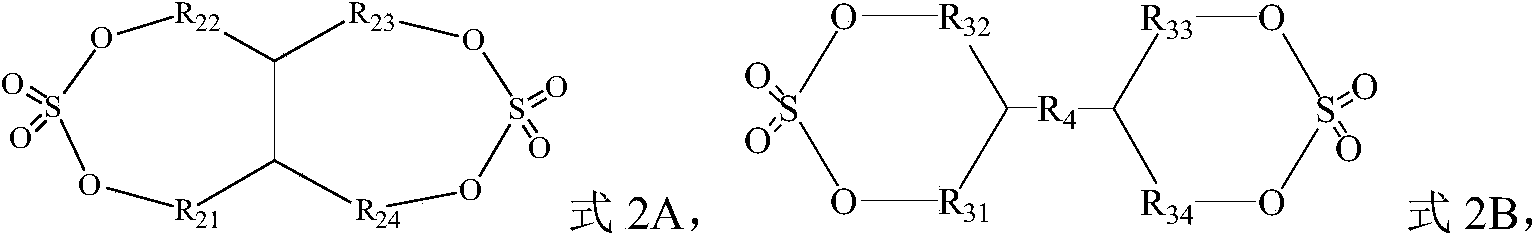 在式2A中,R 21、R 22、R 23、R 24分别独立地为单键、亚甲基中的一种,在式2B中,R 31、R 32、R 33、R 34分别独立地为单键、亚甲基中的一种,R 4为单键、-O-、C1~C3亚烷基、C1~C3卤代亚烷基、C1~C3氧杂亚烷基中的一种。
 - 根据权利要求1所述的电解液,其中,R 1和R 2分别独立地为甲基、乙基、丙基、氟代甲基、氟代乙基、氟代丙基中的一种;和/或R 21、R 22、R 23、R 24不同时为单键,可选地,R 21、R 22中的一个或两个为亚甲基,R 23、R 24中的一个或两个为亚甲基;和/或R 31、R 32、R 33、R 34分别独立地为单键、亚甲基中的一种,且R 31、R 32、R 33、R 34不同时为单键;和/或R 4为单键、-O-、亚甲基、亚乙基、亚丙基、氟代亚甲基、氟代亚乙基、氟代亚丙基、亚甲氧基、亚乙氧基、亚丙氧基中的一种,可选地,R 4为单键、亚甲基、亚乙基、亚丙基中的一种。
- 根据权利要求1~2任一项所述的电解液,其中,R 31、R 32、R 33、R 34、R 4还满足下述(1)~(6)中的一个:(1)R 4为单键,R 31、R 32中的一个或两个为亚甲基,其余为单键,(2)R 4为单键,R 33、R 34中的一个或两个为亚甲基,其余为单键,(3)R 4为单键,R 31、R 32中的一个为亚甲基,R 33、R 34中的一个为亚甲基,其余为单键,(4)R 4为单键,R 31、R 32均为亚甲基,R 33、R 34中的一个为亚甲基,其余为单键,(5)R 4为单键,R 33、R 34均为亚甲基,R 31、R 32中的一个为亚甲基,其余为单键,(6)R 4为单键,R 31、R 32、R 33、R 34均为亚甲基。
- 根据权利要求1~3任一项所述的电解液,其中,第一有机溶剂选自如下化合物中的一种或几种:
 可选地,第一有机溶剂选自如下化合物中的一种或两种:
- 根据权利要求1~4任一项所述的电解液,其中,第一添加剂选自如下化合物中的一种或几种:
 可选地,第一添加剂选自如下化合物中的一种或几种:
- 根据权利要求1~5任一项所述的电解液,其中,基于所述有机溶剂的总质量,第一有机溶剂的质量百分数为w1,w1的范围为20%~80%,可选地为30%~70%。
- 根据权利要求1~6任一项所述的电解液,其中,基于所述电解液的总质量,第一添加剂的质量百分数为w2,w2的范围为0.1%~10%,可选地为0.5%~5%。
- 根据权利要求1~7任一项所述的电解液,其中,所述添加剂还包括第二添加剂,所述第二添加剂包括含有不饱和键的环状碳酸酯化合物、卤素取代的环状碳酸酯化合物、硫酸酯化合物、亚硫酸酯化合物、磺酸内酯化合物、二磺酸化合物、腈化合物、芳 香化合物、异氰酸酯化合物、磷腈化合物、环状酸酐化合物、亚磷酸酯化合物、磷酸酯化合物、硼酸酯化合物、羧酸酯化合物中的一种或几种,可选地,所述第二添加剂包括如下化合物中的一种或两种:

- 根据权利要求1~8任一项所述的电解液,其中,基于所述电解液的总质量,第二添加剂的质量百分数为w3,w3的范围为≤10%,可选地≤5%。
- 根据权利要求1~9任一项所述的电解液,其中,所述有机溶剂还包括第二有机溶剂,所述第二有机溶剂包括环状碳酸酯化合物、链状碳酸酯化合物中的一种或几种,可选地包括环状碳酸酯化合物、或包括环状碳酸酯化合物与链状碳酸酯化合物的组合。
- 根据权利要求1~10任一项所述的电解液,其中,所述有机溶剂还包括第二有机溶剂,所述第二有机溶剂包括碳酸乙烯酯、碳酸丙烯酯、碳酸1,2-丁烯酯、碳酸二甲酯、碳酸甲乙酯、碳酸二乙酯、碳酸二丙酯、碳酸甲丙酯、碳酸乙丙酯中的一种或几种。
- 根据权利要求1~11所述的电解液,其中,基于所述有机溶剂的总质量,环状碳酸酯化合物的质量百分数为w4,w4的范围为20%~80%,可选地为20%~50%。
- 根据权利要求1~12任一项所述的电解液,其中,所述电解液还包括锂盐,所述锂盐包括LiN(C xF 2x+1SO 2)(C yF 2y+1SO 2)、LiPF 6、LiBF 4、LiBOB、LiDFOB、LiPO 2F 2、LiDFOP、LiTFOP、LiAsF 6、Li(FSO 2) 2N、LiCF 3SO 3以及LiClO 4中的一种或几种,其中,x、y为正整数。
- 根据权利要求1~13任一项所述的电解液,其中,所述电解液的电导率满足≥12mS/cm,可选地满足≥13mS/cm,更具体地,所述电解液的电导率为12mS/cm~24mS/cm或13mS/cm~20mS/cm。
- 一种二次电池,包括根据权利要求1~14任一项所述的电解液。
- 根据权利要求15所述的二次电池,其中,所述二次电池包括负极极片,所述负极极片包括负极集流体以及设置在负极集流体至少一个表面上且包括负极活性材料的负极膜层,单面负极膜层的厚度H与负极活性材料的体积平均粒径Dv50的比值H/Dv50满足≥3,可选地满足4≤H/Dv50≤9。
- 根据权利要求15~16任一项所述的二次电池,其中,单面负极膜层的厚度H满足≥60μm,可选地满足≥65μm;和/或负极活性材料的体积平均粒径Dv50满足≤18μm,可选地满足14μm≤Dv50≤18μm。
- 根据权利要求15~17任一项所述的二次电池,其中,负极膜层的压实密度为1.4g/cm 3~1.85g/cm 3,可选地为1.6g/cm 3~1.8g/cm 3。
- 根据权利要求15~18任一项所述的二次电池,其中,所述二次电池包括正极极片,所述正极极片包括正极活性材料,所述正极活性材料包括锂过渡金属氧化物、橄榄石结构的含锂磷酸盐及其各自的改性化合物中的一种或几种,可选地,橄榄石结构的含锂磷酸盐包括磷酸铁锂、磷酸铁锂与碳的复合材料、磷酸锰锂、磷酸锰锂与碳的复合材料、磷酸锰铁锂、磷酸锰铁锂与碳的复合材料及其改性化合物中的一种或几种。
- 一种电池模块,包括根据权利要求15~19任一项所述的二次电池。
- 一种电池包,包括根据权利要求15~19任一项所述的二次电池、根据权利要求20所述的电池模块中的一种。
- 一种用电装置,包括根据权利要求15~19任一项所述的二次电池、根据权利要求20所述的电池模块、根据权利要求21所述的电池包中的至少一种。
Priority Applications (9)
| Application Number | Priority Date | Filing Date | Title |
|---|---|---|---|
| PL21946250.4T PL4160773T3 (pl) | 2021-07-30 | 2021-07-30 | Elektrolit, akumulator wtórny, moduł akumulatorowy, pakiet akumulatorów i urządzenie elektryczne |
| CN202180073107.7A CN116349050B (zh) | 2021-07-30 | 2021-07-30 | 电解液、二次电池、电池模块、电池包和用电装置 |
| EP21946250.4A EP4160773B1 (en) | 2021-07-30 | 2021-07-30 | Electrolyte, secondary battery, battery module, battery pack, and electric device |
| KR1020237001282A KR102889485B1 (ko) | 2021-07-30 | 2021-07-30 | 전해액, 이차 전지, 전지 모듈, 전지 팩 및 전기 장치 |
| EP25213006.7A EP4734215A2 (en) | 2021-07-30 | 2021-07-30 | Electrolyte solution, secondary battery, battery module, battery pack and powered device |
| JP2023501614A JP7653505B2 (ja) | 2021-07-30 | 2021-07-30 | 電解液、二次電池、電池モジュール、電池パック及び電気装置 |
| ES21946250T ES3060465T3 (en) | 2021-07-30 | 2021-07-30 | Electrolyte, secondary battery, battery module, battery pack, and electric device |
| PCT/CN2021/109905 WO2023004821A1 (zh) | 2021-07-30 | 2021-07-30 | 电解液、二次电池、电池模块、电池包和用电装置 |
| US18/322,597 US20230318042A1 (en) | 2021-07-30 | 2023-05-24 | Electrolyte solution, secondary battery, battery module, battery pack and powered device |
Applications Claiming Priority (1)
| Application Number | Priority Date | Filing Date | Title |
|---|---|---|---|
| PCT/CN2021/109905 WO2023004821A1 (zh) | 2021-07-30 | 2021-07-30 | 电解液、二次电池、电池模块、电池包和用电装置 |
Related Child Applications (1)
| Application Number | Title | Priority Date | Filing Date |
|---|---|---|---|
| US18/322,597 Continuation US20230318042A1 (en) | 2021-07-30 | 2023-05-24 | Electrolyte solution, secondary battery, battery module, battery pack and powered device |
Publications (1)
| Publication Number | Publication Date |
|---|---|
| WO2023004821A1 true WO2023004821A1 (zh) | 2023-02-02 |
Family
ID=85087387
Family Applications (1)
| Application Number | Title | Priority Date | Filing Date |
|---|---|---|---|
| PCT/CN2021/109905 Ceased WO2023004821A1 (zh) | 2021-07-30 | 2021-07-30 | 电解液、二次电池、电池模块、电池包和用电装置 |
Country Status (8)
| Country | Link |
|---|---|
| US (1) | US20230318042A1 (zh) |
| EP (2) | EP4160773B1 (zh) |
| JP (1) | JP7653505B2 (zh) |
| KR (1) | KR102889485B1 (zh) |
| CN (1) | CN116349050B (zh) |
| ES (1) | ES3060465T3 (zh) |
| PL (1) | PL4160773T3 (zh) |
| WO (1) | WO2023004821A1 (zh) |
Cited By (6)
| Publication number | Priority date | Publication date | Assignee | Title |
|---|---|---|---|---|
| CN117543071A (zh) * | 2023-09-28 | 2024-02-09 | 深圳市贝特瑞新能源技术研究院有限公司 | 半固态电池及其制造方法和检测方法 |
| WO2024197714A1 (zh) * | 2023-03-30 | 2024-10-03 | 宁德时代新能源科技股份有限公司 | 钠离子电池用电解液、钠离子电池单体和二次电池 |
| CN119823092A (zh) * | 2025-03-14 | 2025-04-15 | 江苏华盛锂电材料股份有限公司 | 硫酸乙烯酯类化合物、合成方法及其在二次电池中的应用 |
| WO2025086283A1 (zh) * | 2023-10-27 | 2025-05-01 | 宁德新能源科技有限公司 | 一种二次电池和电子装置 |
| WO2025197263A1 (ja) * | 2024-03-21 | 2025-09-25 | Muアイオニックソリューションズ株式会社 | 電解液及びその製造方法、電池及びその製造方法、並びに該電池を搭載する車両 |
| CN121192252A (zh) * | 2025-11-24 | 2025-12-23 | 华南理工大学 | 一种非水电解液及锂离子电池 |
Families Citing this family (5)
| Publication number | Priority date | Publication date | Assignee | Title |
|---|---|---|---|---|
| WO2024205203A1 (ko) * | 2023-03-26 | 2024-10-03 | 삼성에스디아이주식회사 | 전해질 및 이를 포함하는 리튬전지 |
| KR102869523B1 (ko) * | 2023-03-26 | 2025-10-14 | 삼성에스디아이 주식회사 | 전해질 및 이를 포함하는 리튬전지 |
| CN117393858A (zh) * | 2023-12-08 | 2024-01-12 | 宁德时代新能源科技股份有限公司 | 锂二次电池、其制备方法和用电装置 |
| KR20260021816A (ko) * | 2024-06-28 | 2026-02-13 | 컨템포러리 엠퍼렉스 테크놀로지 씨오., 리미티드 | 이차 전지 및 전기 장치 |
| WO2026020389A1 (zh) * | 2024-07-24 | 2026-01-29 | 宁德时代新能源科技股份有限公司 | 电池单体、电池装置、用电装置 |
Citations (7)
| Publication number | Priority date | Publication date | Assignee | Title |
|---|---|---|---|---|
| CN107086324A (zh) * | 2016-02-12 | 2017-08-22 | 三星Sdi株式会社 | 有机电解液和包含该有机电解液的锂电池 |
| WO2018097523A1 (ko) * | 2016-11-23 | 2018-05-31 | 에스케이케미칼주식회사 | 이차전지용 전해액 및 이를 포함하는 이차전지 |
| KR20180119842A (ko) * | 2017-04-26 | 2018-11-05 | 에스케이케미칼 주식회사 | 이차전지용 전해액 및 이를 포함하는 이차전지 |
| US20190067741A1 (en) * | 2015-06-08 | 2019-02-28 | Sk Innovation Co., Ltd. | Electrolyte for Lithium Secondary Battery and Lithium Secondary Battery Containing the Same |
| CN109950621A (zh) * | 2017-12-21 | 2019-06-28 | 深圳新宙邦科技股份有限公司 | 一种锂离子电池非水电解液及锂离子电池 |
| CN110931869A (zh) * | 2019-12-02 | 2020-03-27 | 广州天赐高新材料股份有限公司 | 一种高温型锂二次电池电解液及电池 |
| CN111293357A (zh) * | 2018-12-10 | 2020-06-16 | 张家港市国泰华荣化工新材料有限公司 | 一种非水电解液及其应用 |
Family Cites Families (14)
| Publication number | Priority date | Publication date | Assignee | Title |
|---|---|---|---|---|
| CN101286573A (zh) * | 2007-04-09 | 2008-10-15 | 比亚迪股份有限公司 | 一种电解液及含有该电解液的锂离子二次电池 |
| KR20150079586A (ko) * | 2012-10-22 | 2015-07-08 | 아사히 가라스 가부시키가이샤 | 이차 전지용 비수 전해액 및 리튬 이온 이차 전지 |
| JP6631404B2 (ja) * | 2016-05-19 | 2020-01-15 | 株式会社Gsユアサ | 非水電解液二次電池用非水電解液、非水電解液二次電池、及び非水電解液二次電池の製造方法 |
| JP2018092778A (ja) * | 2016-12-02 | 2018-06-14 | 日立化成株式会社 | リチウムイオン二次電池 |
| JP7128422B2 (ja) * | 2017-04-10 | 2022-08-31 | セントラル硝子株式会社 | ホスホリルイミド塩の製造方法、該塩を含む非水電解液の製造方法及び非水二次電池の製造方法 |
| CN107171022B (zh) * | 2017-06-14 | 2019-10-29 | 厦门首能科技有限公司 | 一种锂离子电解液及其锂离子电池 |
| EP3662532A4 (en) * | 2017-07-31 | 2021-09-08 | Tesla Motors Canada ULC | NEW BATTERY SYSTEMS BASED ON LITHIUM DIFLUORPHOSPHATE |
| CN111902990A (zh) * | 2018-03-29 | 2020-11-06 | 松下知识产权经营株式会社 | 电化学器件 |
| CN110660963B (zh) * | 2018-12-29 | 2021-04-27 | 宁德时代新能源科技股份有限公司 | 一种电极极片和电化学装置 |
| US11462769B2 (en) * | 2019-12-03 | 2022-10-04 | Enevate Corporation | Silicon-based energy storage devices with electrolyte containing a benzoyl peroxide based compound |
| CN118919728A (zh) * | 2019-12-25 | 2024-11-08 | 宁德新能源科技有限公司 | 电化学装置及包含其的电子装置 |
| JP7509869B2 (ja) * | 2019-12-25 | 2024-07-02 | 寧徳新能源科技有限公司 | 電気化学装置及びそれを含む電子装置 |
| JP7156263B2 (ja) * | 2019-12-25 | 2022-10-19 | トヨタ自動車株式会社 | 全固体電池および全固体電池の製造方法 |
| KR102887987B1 (ko) * | 2020-01-20 | 2025-11-19 | 닝더 엠프렉스 테크놀로지 리미티드 | 전해액 및 이를 사용하는 전기화학 디바이스 |
-
2021
- 2021-07-30 WO PCT/CN2021/109905 patent/WO2023004821A1/zh not_active Ceased
- 2021-07-30 ES ES21946250T patent/ES3060465T3/es active Active
- 2021-07-30 KR KR1020237001282A patent/KR102889485B1/ko active Active
- 2021-07-30 PL PL21946250.4T patent/PL4160773T3/pl unknown
- 2021-07-30 CN CN202180073107.7A patent/CN116349050B/zh active Active
- 2021-07-30 EP EP21946250.4A patent/EP4160773B1/en active Active
- 2021-07-30 EP EP25213006.7A patent/EP4734215A2/en active Pending
- 2021-07-30 JP JP2023501614A patent/JP7653505B2/ja active Active
-
2023
- 2023-05-24 US US18/322,597 patent/US20230318042A1/en active Pending
Patent Citations (7)
| Publication number | Priority date | Publication date | Assignee | Title |
|---|---|---|---|---|
| US20190067741A1 (en) * | 2015-06-08 | 2019-02-28 | Sk Innovation Co., Ltd. | Electrolyte for Lithium Secondary Battery and Lithium Secondary Battery Containing the Same |
| CN107086324A (zh) * | 2016-02-12 | 2017-08-22 | 三星Sdi株式会社 | 有机电解液和包含该有机电解液的锂电池 |
| WO2018097523A1 (ko) * | 2016-11-23 | 2018-05-31 | 에스케이케미칼주식회사 | 이차전지용 전해액 및 이를 포함하는 이차전지 |
| KR20180119842A (ko) * | 2017-04-26 | 2018-11-05 | 에스케이케미칼 주식회사 | 이차전지용 전해액 및 이를 포함하는 이차전지 |
| CN109950621A (zh) * | 2017-12-21 | 2019-06-28 | 深圳新宙邦科技股份有限公司 | 一种锂离子电池非水电解液及锂离子电池 |
| CN111293357A (zh) * | 2018-12-10 | 2020-06-16 | 张家港市国泰华荣化工新材料有限公司 | 一种非水电解液及其应用 |
| CN110931869A (zh) * | 2019-12-02 | 2020-03-27 | 广州天赐高新材料股份有限公司 | 一种高温型锂二次电池电解液及电池 |
Non-Patent Citations (1)
| Title |
|---|
| See also references of EP4160773A4 * |
Cited By (6)
| Publication number | Priority date | Publication date | Assignee | Title |
|---|---|---|---|---|
| WO2024197714A1 (zh) * | 2023-03-30 | 2024-10-03 | 宁德时代新能源科技股份有限公司 | 钠离子电池用电解液、钠离子电池单体和二次电池 |
| CN117543071A (zh) * | 2023-09-28 | 2024-02-09 | 深圳市贝特瑞新能源技术研究院有限公司 | 半固态电池及其制造方法和检测方法 |
| WO2025086283A1 (zh) * | 2023-10-27 | 2025-05-01 | 宁德新能源科技有限公司 | 一种二次电池和电子装置 |
| WO2025197263A1 (ja) * | 2024-03-21 | 2025-09-25 | Muアイオニックソリューションズ株式会社 | 電解液及びその製造方法、電池及びその製造方法、並びに該電池を搭載する車両 |
| CN119823092A (zh) * | 2025-03-14 | 2025-04-15 | 江苏华盛锂电材料股份有限公司 | 硫酸乙烯酯类化合物、合成方法及其在二次电池中的应用 |
| CN121192252A (zh) * | 2025-11-24 | 2025-12-23 | 华南理工大学 | 一种非水电解液及锂离子电池 |
Also Published As
| Publication number | Publication date |
|---|---|
| EP4160773B1 (en) | 2025-11-05 |
| KR20230023765A (ko) | 2023-02-17 |
| CN116349050A (zh) | 2023-06-27 |
| JP2023538722A (ja) | 2023-09-11 |
| CN116349050B (zh) | 2026-03-03 |
| EP4160773A1 (en) | 2023-04-05 |
| PL4160773T3 (pl) | 2026-03-30 |
| US20230318042A1 (en) | 2023-10-05 |
| EP4734215A2 (en) | 2026-04-29 |
| KR102889485B1 (ko) | 2025-11-21 |
| ES3060465T3 (en) | 2026-03-26 |
| EP4160773A4 (en) | 2023-11-08 |
| JP7653505B2 (ja) | 2025-03-28 |
Similar Documents
| Publication | Publication Date | Title |
|---|---|---|
| WO2023004821A1 (zh) | 电解液、二次电池、电池模块、电池包和用电装置 | |
| WO2023213188A1 (zh) | 一种电化学装置 | |
| JP7587501B2 (ja) | 電解液、電気化学装置及び電子装置 | |
| CN116454393B (zh) | 二次电池和装置 | |
| CN112400249A (zh) | 一种电解液及电化学装置 | |
| WO2023039750A1 (zh) | 一种负极复合材料及其应用 | |
| WO2025113667A1 (zh) | 电解液添加剂、电解液、电池、用电装置 | |
| JP2024539298A (ja) | 電気化学装置及びそれを含む電子装置 | |
| WO2023044934A1 (zh) | 二次电池、电池模块、电池包以及用电装置 | |
| CN110061189A (zh) | 锂二次电池 | |
| WO2023137701A1 (zh) | 电化学装置及包含其的电子装置 | |
| US20220223915A1 (en) | Electrolyte, electrochemical device including same, and electronic device | |
| WO2024164167A1 (zh) | 非水电解液和含该非水电解液的二次电池及用电装置 | |
| JP2024539299A (ja) | 電気化学装置およびそれを含む電子装置 | |
| WO2023070287A1 (zh) | 正极极片、电化学装置及电子装置 | |
| CN116235361A (zh) | 快充长寿命型二次电池、电池模块、电池包、用电装置 | |
| CN116420259A (zh) | 电解液、二次电池、电池模块、电池包和用电装置 | |
| CN117199534A (zh) | 一种电解液、电化学装置及电子设备 | |
| CN117199535A (zh) | 一种电解液、电化学装置及电子装置 | |
| CN116111045A (zh) | 正极极片及其制备方法、二次电池和电子装置 | |
| CN101110477B (zh) | 一种电化学储能与能量转换装置 | |
| CN116417569B (zh) | 二次电池和装置 | |
| CN116404258B (zh) | 二次电池和装置 | |
| CN111971845A (zh) | 一种电解液及电化学装置 | |
| US20240356077A1 (en) | Electrochemical device and electronic device including same |
Legal Events
| Date | Code | Title | Description |
|---|---|---|---|
| ENP | Entry into the national phase |
Ref document number: 2023501614 Country of ref document: JP Kind code of ref document: A Ref document number: 20237001282 Country of ref document: KR Kind code of ref document: A |
|
| ENP | Entry into the national phase |
Ref document number: 2021946250 Country of ref document: EP Effective date: 20221229 |
|
| WWE | Wipo information: entry into national phase |
Ref document number: 202327020091 Country of ref document: IN |
|
| NENP | Non-entry into the national phase |
Ref country code: DE |
|
| WWG | Wipo information: grant in national office |
Ref document number: 2021946250 Country of ref document: EP |