WO2023005865A1 - 一种室内地图构建方法以及相关装置 - Google Patents
一种室内地图构建方法以及相关装置 Download PDFInfo
- Publication number
- WO2023005865A1 WO2023005865A1 PCT/CN2022/107579 CN2022107579W WO2023005865A1 WO 2023005865 A1 WO2023005865 A1 WO 2023005865A1 CN 2022107579 W CN2022107579 W CN 2022107579W WO 2023005865 A1 WO2023005865 A1 WO 2023005865A1
- Authority
- WO
- WIPO (PCT)
- Prior art keywords
- trajectory
- track
- points
- wireless signal
- point
- Prior art date
- Legal status (The legal status is an assumption and is not a legal conclusion. Google has not performed a legal analysis and makes no representation as to the accuracy of the status listed.)
- Ceased
Links
Images



Classifications
-
- G—PHYSICS
- G01—MEASURING; TESTING
- G01S—RADIO DIRECTION-FINDING; RADIO NAVIGATION; DETERMINING DISTANCE OR VELOCITY BY USE OF RADIO WAVES; LOCATING OR PRESENCE-DETECTING BY USE OF THE REFLECTION OR RERADIATION OF RADIO WAVES; ANALOGOUS ARRANGEMENTS USING OTHER WAVES
- G01S5/00—Position-fixing by co-ordinating two or more direction or position line determinations; Position-fixing by co-ordinating two or more distance determinations
- G01S5/02—Position-fixing by co-ordinating two or more direction or position line determinations; Position-fixing by co-ordinating two or more distance determinations using radio waves
- G01S5/0252—Radio frequency fingerprinting
- G01S5/02521—Radio frequency fingerprinting using a radio-map
- G01S5/02524—Creating or updating the radio-map
- G01S5/02525—Gathering the radio frequency fingerprints
- G01S5/02526—Gathering the radio frequency fingerprints using non-dedicated equipment, e.g. user equipment or crowd-sourcing
-
- G—PHYSICS
- G06—COMPUTING OR CALCULATING; COUNTING
- G06F—ELECTRIC DIGITAL DATA PROCESSING
- G06F16/00—Information retrieval; Database structures therefor; File system structures therefor
- G06F16/20—Information retrieval; Database structures therefor; File system structures therefor of structured data, e.g. relational data
- G06F16/29—Geographical information databases
-
- G—PHYSICS
- G01—MEASURING; TESTING
- G01C—MEASURING DISTANCES, LEVELS OR BEARINGS; SURVEYING; NAVIGATION; GYROSCOPIC INSTRUMENTS; PHOTOGRAMMETRY OR VIDEOGRAMMETRY
- G01C21/00—Navigation; Navigational instruments not provided for in groups G01C1/00 - G01C19/00
- G01C21/20—Instruments for performing navigational calculations
- G01C21/206—Instruments for performing navigational calculations specially adapted for indoor navigation
-
- G—PHYSICS
- G01—MEASURING; TESTING
- G01C—MEASURING DISTANCES, LEVELS OR BEARINGS; SURVEYING; NAVIGATION; GYROSCOPIC INSTRUMENTS; PHOTOGRAMMETRY OR VIDEOGRAMMETRY
- G01C21/00—Navigation; Navigational instruments not provided for in groups G01C1/00 - G01C19/00
- G01C21/38—Electronic maps specially adapted for navigation; Updating thereof
- G01C21/3804—Creation or updating of map data
- G01C21/3807—Creation or updating of map data characterised by the type of data
- G01C21/383—Indoor data
-
- G—PHYSICS
- G01—MEASURING; TESTING
- G01C—MEASURING DISTANCES, LEVELS OR BEARINGS; SURVEYING; NAVIGATION; GYROSCOPIC INSTRUMENTS; PHOTOGRAMMETRY OR VIDEOGRAMMETRY
- G01C21/00—Navigation; Navigational instruments not provided for in groups G01C1/00 - G01C19/00
- G01C21/38—Electronic maps specially adapted for navigation; Updating thereof
- G01C21/3804—Creation or updating of map data
- G01C21/3833—Creation or updating of map data characterised by the source of data
- G01C21/3841—Data obtained from two or more sources, e.g. probe vehicles
-
- H—ELECTRICITY
- H04—ELECTRIC COMMUNICATION TECHNIQUE
- H04W—WIRELESS COMMUNICATION NETWORKS
- H04W4/00—Services specially adapted for wireless communication networks; Facilities therefor
- H04W4/02—Services making use of location information
- H04W4/029—Location-based management or tracking services
-
- H—ELECTRICITY
- H04—ELECTRIC COMMUNICATION TECHNIQUE
- H04W—WIRELESS COMMUNICATION NETWORKS
- H04W4/00—Services specially adapted for wireless communication networks; Facilities therefor
- H04W4/30—Services specially adapted for particular environments, situations or purposes
- H04W4/33—Services specially adapted for particular environments, situations or purposes for indoor environments, e.g. buildings
Definitions
- the present application relates to the field of computers, and in particular to an indoor map construction method and related devices.
- location-based services have become an increasingly indispensable basic demand for people.
- Most of people's daily activities are indoors, and most of the terminal use and data connection are also indoors, and people's daily activity information is usually related to location and time. Therefore, the demand for location-based services in the mobile Internet era will become more and more bigger and bigger.
- Indoor positioning is a necessary basic technology for the two major application fields of travel and convenient life. Scenes such as shopping malls, underground garages, hospitals, and airports all require indoor positioning to enable smarter mobile service applications. Indoor positioning is the core technology for navigation, social networking, and advertising applications. There are millions of shopping malls and airports around the world that need to deploy indoor positioning technology.
- the original collected crowdsourcing data is a mixture of indoor and outdoor, flat and cross-layer trajectories, and various behavioral states.
- the difficulty of trajectory layering lies in the mixed layers of trajectories. Because there are a large number of elevators, escalators, and staircase structures between the middle floors of shopping malls, as well as large hollow areas, these factors lead to WiFi between floors, etc.
- the wireless signal is unobstructed transmission, so the fingerprint similarity between adjacent layers in these areas cannot be distinguished.
- the track points on both sides of the escalator are unobstructed from each other, so the average
- the track points on the layer track may be located in different plane layers and the wireless signal information is very similar. If the layering of the leveling track is based on these track points, the tracks on different planes may be misidentified as tracks of the same layer.
- the present application provides an indoor map construction method, the method comprising:
- each of the first trajectories is a leveling trajectory located on an indoor horizontal layer
- the second trajectory is a cross-layer trajectory located between different indoor horizontal layers
- each of the The first trajectory includes a plurality of first trajectory points
- the second trajectory includes a plurality of second trajectory points
- each of the first trajectory point and the second trajectory point includes wireless signal information at the location,
- the similarity of the first wireless signal information between each of the first trajectory points and each of the second trajectory points is less than a first threshold
- the leveling trajectory here can be understood as the trajectory on the horizontal plane, such as the trajectory on the horizontal floor indoors, and the cross-floor trajectory can be understood as the trajectory between the various planes in the room, such as the trajectory on the escalator and elevator. track;
- wireless signal information here may refer to signals that can be received in indoor areas, excluding GPS information.
- wireless signal information may include, but is not limited to, WiFi, Bluetooth, signals originating from a base station Cell, fine time measurement (fine time measurement, FTM), ultra wide band (ultra wide band, UWB), geomagnetic field, etc.;
- the first trajectory point and the second trajectory point may include wireless signal information at the location, and the wireless signal information may indicate the strength of the wireless signal received at the location of the trajectory point and the network device transmitting the wireless signal.
- the wireless signal information included in the track point on the leveling track and the second track point is similar, it can be considered that the physical positions of the track point on the leveling track and the second track point are very close or coincident.
- the trace points on the layer trace and the wireless signal information included in the second trace point are eliminated (or marked, the mark can indicate that the wireless signal information is similar and do not participate in the subsequent layering process of the flat layer trace), and participate in the subsequent analysis.
- the first track points of the layer all satisfy: the first wireless signal information similarity between each first track point and each second track point is less than a first threshold;
- the similarity of the first wireless signal information between the first track point and the second track point may be related to the coincidence degree of the identifiers of the network devices included in the first track point and the second track point, when the first track point and the second track point
- the identifiers of the network equipment included in the two track points have only a small number (or proportion) of identifiers overlapping (for example, no overlap at all, or only 1, 2 or 3 identifiers overlap, or only less than 10, 20 or 30 percent of the identifiers overlap), then it can be considered that the similarity of the first wireless signal information between the first track point and the second track point is less than the first threshold;
- the similarity of the first wireless signal information between the first trajectory point and the second trajectory point can also be related to the similarity of the signal strength of the wireless signal included in the first trajectory point and the second trajectory point, when the first trajectory point and the second track point include the same network device identifier, the first wireless signal information similarity between the first track point and the second track point can also be equal to the wireless signal strength of the network device corresponding to the same network device ID It is related to the similarity between them (for example, it can be positively correlated);
- the first wireless signal information similarity between the first track point and the second track point can be quantified based on a similarity value, which coincides with the identity of the network equipment included in the first track point and the second track point It is also related to the wireless signal strength of the network device corresponding to the same network device identifier (for example, positive correlation).
- a similarity value which coincides with the identity of the network equipment included in the first track point and the second track point It is also related to the wireless signal strength of the network device corresponding to the same network device identifier (for example, positive correlation).
- the similarity value is less than the first threshold, it can be considered that the first track point and the second
- the first wireless signal information similarity between the two track points is less than a first threshold;
- the first threshold can be set based on experience, as long as the first threshold can represent that the wireless signal information between the first track point and the second track point is very similar, so that it can affect the accuracy of subsequent flat track layering, This application does not limit the value of the first threshold.
- the multiple first tracks layer the multiple first tracks to obtain a layered result, the layered result Including a plurality of horizontal layers and the first track included in each horizontal layer, wherein the first track whose similarity degree of the second wireless signal information is greater than the second threshold is divided into the same horizontal layer; according to the layered results, the indoor map.
- the second wireless signal information similarity is the wireless signal similarity between trajectories, for example, it can be calculated by the coincidence degree of the identification of the network device included in each trajectory point between the trajectories and the similarity of wireless signal strength;
- the original collected crowdsourcing data is a mixture of indoor and outdoor, flat and cross-layer trajectories, and various behavioral states.
- the difficulty of trajectory layering lies in the mixed layers of trajectories. Because there are a large number of elevators, escalators, and staircase structures between the middle floors of shopping malls, as well as large hollow areas, these factors lead to WiFi between floors, etc. RF signals are transmitted unobstructed, so the fingerprint similarity between tracks between adjacent layers in these regions is indistinguishable, resulting in mixed layers.
- the server can obtain multiple indoor trajectories based on the crowdsourcing data reported by the terminal, where each trajectory point in the indoor trajectory can include sensor information and time at the location (this time can be understood as collecting trajectory points time, or the time to collect the corresponding sensor information), the sensor information of the track point can identify whether the track is a flat track or a cross-layer track.
- the above sensor information may be acceleration information
- the server may identify a high-confidence cross-layer trajectory (second trajectory) through the acceleration information included in the trajectory point.
- the trajectory whose acceleration information satisfies the following conditions may be determined as the second trajectory: the acceleration of each trajectory point in the trajectory in the time series changes from the first state to the second state and then to the third state; wherein , the first state is an increasing state with a rate of change greater than a threshold, the second state is a steady state with a rate of change less than a threshold, and the third state is a decreasing state with a rate of change greater than a threshold; or, the first state The first state is a decreasing state with a rate of change greater than a threshold, the second state is a steady state with a rate of change less than a threshold, and the third state is an increasing state with a rate of change greater than a threshold.
- the rate of change here can be understood as the magnitude of the change value of the acceleration per unit time, for example, it can be the magnitude of the slope on the curve of the acceleration versus time;
- the timing here may be a forward time sequence or a reverse time sequence along the time included in each second track point, for example, a plurality of track points include track point 1, track point 2, track point 3, track point 4, Track point 5, track point 6, track point 7, track point 8, track point 9, track point 10, the time of collecting sensor information included in track point 1 is 0.005, and the time of collecting sensor information included in track point 2 is 0.010,
- the time of collecting sensor information included in track point 3 is 0.015
- the time of collecting sensor information included in track point 4 is 0.02
- the time of collecting sensor information included in track point 5 is 0.025
- the time of collecting sensor information included in track point 6 is 0.03
- the time for collecting sensor information included in track point 7 is 0.035
- the time for collecting sensor information included in track point 8 is 0.04
- the time for collecting sensor information included in track point 9 is 0.045
- the time for collecting sensor information included in track point 10 is 0.035.
- each second track point in the second track on the timing of the time can be by track point 1, track point 2, track point 3, track point 4, track point 5, track point 6 , track point 7, track point 8, track point 9, track point 10 sequence acceleration, or by track point 10, track point 9, track point 8, track point 7, track point 6, track point 5, track point 4. Acceleration in sequence of track point 3, track point 2, and track point 1.
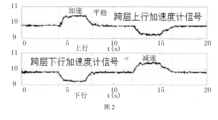
- the accelerometer when the user takes an escalator or an elevator to go up and down the stairs when crossing floors, the accelerometer will have obvious changing characteristics during the upward and downward process.
- the downward direction is opposite, so the cross-layer trajectory can be effectively identified by detecting the change characteristics of the acceleration.
- Each of the second trajectory points in the first trajectory determined based on the above method includes acceleration information collected at the location, and along the direction of the second trajectory, the acceleration of the plurality of second trajectory points is determined by the first A state changes into a second state and then becomes a third state; wherein, the first state is an enlarged state with a rate of change greater than a threshold, the second state is a steady state with a rate of change less than a threshold, and the third state It is a decreasing state with a rate of change greater than a threshold; or, the first state is a decreasing state with a rate of change greater than a threshold, the second state is a steady state with a rate of change less than a threshold, and the third state is a rate of change greater than Increased state of the threshold.
- the wireless signal information is used to indicate the strength of the wireless signal received at the location and the identifier of the network device sending the wireless signal.
- the strength of the wireless signal can also be called the received signal strength (received signal strength, RSS), which specifically refers to the wideband received power received by the terminal on the channel bandwidth, in dBm. Quality, surrounding environment link occlusion, distance from the signal source, etc.;
- RSS received signal strength
- the acquiring a plurality of first trajectories includes: acquiring a plurality of initial trajectories, each initial trajectory includes a plurality of trajectory points, each of the trajectory points includes a wireless signal received at a location Signal information, each of the initial trajectories is a leveling trajectory located on the indoor horizontal layer; it is determined that the wireless signal information between the multiple trajectory points included in the multiple initial trajectories is similar to that between each second trajectory point A trajectory point whose degree is smaller than the first threshold is the first trajectory point, so as to acquire the first trajectory.
- the first trajectory point can be marked, and the mark can indicate that the trajectory point is used in the subsequent stratification of the leveling trajectory, and the initial trajectory except the first trajectory point Other track points are eliminated, or not marked.
- trajectory points in the initial trajectory except the first trajectory point can be eliminated, or marked, and the mark can indicate that the trajectory point can be used for subsequent stratification of the leveling trajectory. Not to be used, or through other operations that can indicate that the track point is not to be used in the subsequent layering of the leveling track, which is not limited here.
- the method also includes:
- the third track point includes wireless signal information and GPS information at the location, the wireless signal between the third track point and the target track point in the plurality of first track points
- the information similarity is greater than a third threshold
- the GPS information is used to indicate the absolute position of the target track point
- the target track point also includes relative positions in the plurality of first tracks; according to the absolute position and For the relative position, determine a position conversion relationship, and determine the absolute positions of the plurality of first trajectory points according to the position conversion relationship.
- the wireless signal information similarity between the third track point and the second track point may be related to the coincidence degree of the identifier of the network device included in the third track point and the first track point, when the third track point and the first track point Points include only a small number (or proportion) of identities of network devices that overlap (for example, no overlap at all, or only 1, 2, or 3 identities overlap, or only less than 10, 20, or 30 percent of identities overlap) , it can be considered that the wireless signal information similarity between the third track point and the first track point is less than the third threshold;
- the wireless signal information similarity between the third track point and the first track point can also be related to the similarity of the signal strength of the wireless signal included in the third track point and the first track point, when the third track point and the first track point If one track point includes the same network device identifier, the wireless signal information similarity between the third track point and the first track point can also be the same as the similarity between the wireless signal strengths of the network devices corresponding to the same network device ID related (for example, may be positively related);
- the wireless signal information similarity between the third track point and the first track point can be quantified based on a similarity value, which is related to the coincidence degree of the identification of the network equipment included in the third track point and the first track point (for example, positive correlation), and also related to the wireless signal strength of the network equipment corresponding to the same network equipment identification included (for example, positive correlation), when the similarity value is greater than the third threshold, it can be considered that the third trajectory point and the first trajectory
- a similarity value which is related to the coincidence degree of the identification of the network equipment included in the third track point and the first track point (for example, positive correlation), and also related to the wireless signal strength of the network equipment corresponding to the same network equipment identification included (for example, positive correlation)
- the similarity value is greater than the third threshold
- the third threshold can be set based on experience, as long as the third threshold can represent that the wireless signal information between the third track point and the first track point is very similar, basically it can be considered that the third track point and the first track point are completely coincident Or basically overlap, this application does not limit the value of the third threshold;
- the GPS information here is used to indicate the absolute position of the target track point, it can be understood that the GPS information can indicate the absolute position of the third track point, because the wireless signal information between the third track point and the target track point is similar degree is very large, it can be considered that the third track point and the target track point completely coincide or basically coincide in physical position, then the GPS information can be used as the absolute position of the target track point, for example, the absolute position of the GPS information can be directly assigned to the target track point;
- the GPS information can include absolute position information (such as geographical coordinates, etc.), and can also include the uncertainty of the absolute position information (because the third track point and the first track point may not be strictly coincident, then it can be based on the third track point and the first track point.
- the similarity of wireless signal information between target track points is used to determine the uncertainty of a GPS information.
- the uncertainty here can also be related to the confidence information carried by the GPS information itself.
- the confidence information can indicate the absolute position in the GPS information. accuracy);
- the obtaining the third trajectory point includes: obtaining a plurality of first candidate trajectory points, and the confidence degree and indoor and outdoor status of each first candidate trajectory point, each of the first candidate trajectory points
- the point includes wireless signal information; according to the confidence degree and indoor and outdoor status of each first candidate trajectory point and the included wireless signal information, perform wireless signal similarity between the plurality of first candidate trajectory points and the plurality of first trajectory points Degree comparison, to determine M first candidate track points whose wireless signal similarity is greater than a threshold from the plurality of candidate track points, the confidence of each of the first candidate track points is greater than a threshold and is in an outdoor state, so
- the M first candidate track points include the third track point, and M is a positive integer.
- the confidence degree here may be accuracy information (accuracy, ACC) carried in the GPS information, or information that can indicate the positioning reliability of the GPS information calculated based on the GPS information;
- the indoor and outdoor status here can be determined based on the GNSS status (GNSS status) in the GPS information.
- GNSS status GNSS status
- the indoor and outdoor status can be determined based on the following manner:
- an indoor and outdoor state classifier is trained based on logistic regression
- the switching point is identified as the indoor and outdoor switching position based on the state sequence of indoor and outdoor identification.
- M here may be a positive integer greater than or equal to 3, and the determined M first candidate trajectory points are not collinear trajectory points.
- the method further includes: acquiring a plurality of second candidate trajectory points, each of which includes wireless signal information and is in an indoor-outdoor switching state; Points are compared with the multiple first track points included in each horizontal layer for wireless signal similarity, so as to determine the first track point whose wireless signal similarity is greater than a threshold from the multiple first track points included in each horizontal layer
- Two candidate trajectory points according to the number of second candidate trajectory points determined for each horizontal layer, determine the absolute floor of the horizontal layer with the largest number of determined second candidate trajectory points.
- the difference degree of wireless signal information between different second trajectory candidate points is very large, thereby ensuring that the determined second candidate trajectory point can indicate an entrance and exit, and different from the second candidate trajectory point Track points can indicate different exits and exits;
- the quantity of the determined second candidate trajectory points can represent the quantity of entrances and exits
- the absolute floor here can be the absolute first floor (because most buildings will be indoors on the ground floor (that is, the floor number is the absolute first floor)
- the number of entrances and exits is set the most, so the floor with the largest number of entrances and exits can be the absolute 1st floor), and the absolute floor here can also be other absolute floors (for example, in some shopping malls, the floor with the most entrances and exits is marked as B1 floor , 2 floors or other non-1 floors);
- the upper and lower floors relationship between each of the horizontal floors in the layering result is determined according to the uplink and downlink information of the trajectory indicated by the second trajectory; according to the determined second candidate trajectory point
- the track uplink and downlink information indicated by the second track can be determined based on sensor information (such as barometer, acceleration information, etc.) The upper and lower relationship of layers in physical space;
- the number of second traces may be multiple, and multiple second traces may indicate the uplink-downlink relationship between each horizontal layer;
- the floor with the largest number of matches with the entrance and exit fingerprint database is determined as the absolute first floor, and then the absolute floor number of each floor is updated according to the floor sorting relationship, and the absolute mapping of the 3D skeleton floor is realized without relying on the indoor map.
- the present application provides an indoor map construction device, the device comprising:
- An acquisition module configured to acquire a plurality of first trajectories and second trajectories, each of the first trajectories is a leveling trajectory located on an indoor horizontal layer, and the second trajectory is a cross-floor trajectory located between different indoor horizontal layers trajectory, each of the first trajectory includes a plurality of first trajectory points, and the second trajectory includes a plurality of second trajectory points, and each of the first trajectory points and the second trajectory points includes a location where wireless signal information, and the similarity of the first wireless signal information between each of the first track points and each of the second track points is less than a first threshold;
- a stratification module configured to perform stratification on the plurality of first trajectories according to the second wireless signal information similarity between the plurality of first trajectory points included in the plurality of first trajectories, so as to obtain a stratification result , the hierarchical result includes a plurality of horizontal layers and a first track included in each horizontal layer, wherein the first track whose information similarity of the second wireless signal is greater than a second threshold is divided into the same horizontal layer;
- a map construction module configured to construct an indoor map according to the layered result and the second trajectory.
- the original collected crowdsourcing data is a mixture of indoor and outdoor, flat and cross-layer trajectories, and various behavioral states.
- the difficulty of trajectory layering lies in the mixed layers of trajectories. Because there are a large number of elevators, escalators, and staircase structures between the middle floors of shopping malls, as well as large hollow areas, these factors lead to WiFi between floors, etc. RF signals are transmitted unobstructed, so the fingerprint similarity between tracks between adjacent layers in these regions is indistinguishable, resulting in mixed layers.
- each of the second trajectory points further includes acceleration information and time at the location, and the acceleration of the second trajectory changes from the first state to the second state at the time sequence of the time.
- the state becomes the third state again; among them,
- the first state is an increasing state with a rate of change greater than a threshold
- the second state is a steady state with a rate of change less than a threshold
- the third state is a decreasing state with a rate of change greater than a threshold
- the first state is a decreasing state with a rate of change greater than a threshold
- the second state is a steady state with a rate of change less than a threshold
- the third state is an increasing state with a rate of change greater than a threshold.
- the accelerometer When the user crosses floors, such as taking an escalator or an elevator to go up and down the stairs, the accelerometer will have obvious changes in the process of going up and down.
- the cross-layer trajectory can be effectively identified by detecting the change characteristics of the acceleration.
- the wireless signal information is used to indicate the strength of the wireless signal received at the location and the identifier of the network device sending the wireless signal.
- the strength of the wireless signal can also be called the received signal strength (received signal strength, RSS), which specifically refers to the wideband received power received by the terminal on the channel bandwidth, in dBm. Quality, surrounding environment link occlusion, distance from the signal source, etc.;
- RSS received signal strength
- the acquisition module is also used to:
- each initial trajectory includes a plurality of trajectory points, each of which includes wireless signal information received at the location, and each of the initial trajectories is a flat on the indoor horizontal layer layer track;
- a trajectory point whose wireless signal information similarity with each second trajectory point is smaller than the first threshold is the first trajectory point, so as to obtain the first track.
- the acquisition module is also used to:
- the third track point includes wireless signal information and GPS information at the location, the wireless signal between the third track point and the target track point in the plurality of first track points
- the information similarity is greater than a third threshold
- the GPS information is used to indicate the absolute position of the target track point
- the target track point also includes a relative position in the plurality of first tracks
- a position conversion relationship is determined according to the absolute position and the relative position, and absolute positions of a plurality of first track points included in each of the first tracks are determined according to the position conversion relationship.
- the acquiring module is specifically used for:
- each of the first candidate track points including wireless signal information
- the multiple first candidate track points are compared with the multiple first track points for wireless signal similarity, so as to obtain Among the plurality of candidate track points, it is determined that M first candidate track points whose wireless signal similarity is greater than a threshold, each of the first candidate track points has a confidence level greater than a threshold and is in an outdoor state, and the M first candidate track points
- the track points include the third track point, and the M is a positive integer.
- the acquiring module is specifically used for:
- each second candidate track point includes wireless signal information and is in an indoor-outdoor switching state
- the floor determination module is also used for:
- the absolute floor of each of the horizontal floors in the stratification result is determined.
- the floor with the largest number of matches with the entrance and exit fingerprint database is determined as the absolute first floor, and then the absolute floor number of each floor is updated according to the floor sorting relationship, and the absolute mapping of the 3D skeleton floor is realized without relying on the indoor map.
- an embodiment of the present application provides a computer-readable storage medium, which is characterized by including computer-readable instructions, and when the computer-readable instructions are run on a computer device, the computer device is made to execute the above-mentioned first aspect. and any of its optional methods.
- an embodiment of the present application provides a computer program product, which is characterized by including computer-readable instructions, and when the computer-readable instructions are run on a computer device, the computer device is made to execute the above-mentioned first aspect and its Either method is optional.
- the present application provides a system-on-a-chip, which includes a processor, configured to support a computing device in implementing the functions involved in the above-mentioned aspects, for example, sending or processing the data involved in the above-mentioned method; or, information .
- the chip system further includes a memory, and the memory is used for storing necessary program instructions and data of the computing device.
- the system-on-a-chip may consist of chips, or may include chips and other discrete devices.
- the present application provides a server, which is characterized by comprising: one or more processors and a memory; wherein, computer-readable instructions are stored in the memory; the one or more processors read The computer-readable instructions enable the computer device to execute the above-mentioned first aspect and any optional method thereof.
- the server further includes a communication interface
- the communication interface is used to receive a location query instruction from a terminal device
- the one or more processors are further configured to determine a location query result according to the location query instruction and the indoor map;
- the communication interface is also used to send the location query result to the terminal device.
- An embodiment of the present application provides an indoor map construction method, the method comprising: acquiring a plurality of first trajectories and second trajectories, each of the first trajectories is a leveling trajectory located on an indoor horizontal layer, and the first trajectories
- the second trajectory is a cross-layer trajectory located between different horizontal layers in the room, each of the first trajectory includes a plurality of first trajectory points, and the second trajectory includes a plurality of second trajectory points, and each of the first trajectory
- the point and the second trajectory point include wireless signal information at the location, and the first wireless signal information similarity between each of the first trajectory points and each of the second trajectory points is less than a first threshold ;
- layering the multiple first tracks to obtain a layered result, the layering The result includes a plurality of horizontal layers and the first track included in each horizontal layer, wherein the first track whose similarity degree of the second wireless signal information is greater than the second threshold is divided into
- FIG. 1 is a schematic diagram of an indoor map construction method provided by an embodiment of the present application.
- FIG. 2 is a schematic diagram of the cross-layer trajectory identification provided by the embodiment of the present application.
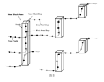
- FIG. 3 is a schematic diagram of the trajectory provided by the embodiment of the present application.
- FIG. 4 and FIG. 5 are schematic diagrams of track point matching provided by the embodiment of the present application.
- FIG. 6 is a schematic diagram of branch generation and branch merging provided by the embodiment of the present application.
- FIG 11a and Figure 11b are schematic diagrams of the indoor map construction method provided by the embodiment of the present application.
- FIG. 12 is a schematic diagram of an indoor map provided by an embodiment of the present application.
- FIG. 13a to 13d are schematic diagrams of the indoor map construction method provided by the embodiment of the present application.
- FIG. 14 is a schematic diagram of an indoor map construction device provided by an embodiment of the present application.
- FIG. 15 is a schematic structural diagram of a terminal provided in an embodiment of the present application.
- FIG. 16 is a schematic structural diagram of a server provided by an embodiment of the present application.
- FIG. 17 is a schematic structural diagram of a chip provided in an embodiment of the present application.
- Fig. 18 is a schematic diagram of a system provided by an embodiment of the present application.
- Fingerprint Use wireless signals (such as terminal base station signals, WIFI signals for wireless LAN communication), ubiquitous geomagnetic signals, or small-range signals emitted by deployed Bluetooth signal tags, etc., to measure and record these signals
- the unique identification name of the signal point for example: Medium Access Control (MAC) address
- MAC Medium Access Control
- signal strength for example: Signal strength
- Each stored location point and corresponding record information may be called a "fingerprint”.
- the real-time location can be obtained through successful "fingerprint" matching, and the positioning function can be realized.
- Location characteristics Nearly stable location points in the main indoor structure, including entry and exit points, doors, elevators, stairs, escalators, corridors, open areas, corners, etc.
- Movement characteristics the typical movement characteristics of the user, which may include movement characteristics such as standing still, walking, running, turning, going up/down stairs, etc.
- Map matching based on the identified location features and actual running trajectory, matching the location points provided by the map and the connection relationship between different areas in the map, and correcting the actual moving route and positioning points to the accurate path and location points.
- Received signal strength specifically refers to the wideband received power received by the terminal on the channel bandwidth, unit dBm, this value is a relative value, the size is related to the terminal receiving antenna quality, surrounding environment link occlusion, and signal transmission related to the distance between the sources.
- Dynamic time warping (dynamic time warping, DTW): Based on the idea of dynamic programming, it solves the problem of template matching with different pronunciation lengths. It is an earlier and more classic algorithm in speech recognition. There are almost no Additional calculations are required. In the application of geomagnetic matching, this algorithm is adopted to solve the problem of pulling up or compressing the signal caused by different user speeds during the real-time positioning process, so as to ensure the correct matching with the original data.
- Pedestrian dead reckoning A method for estimating the distance and direction of pedestrian movement based on the characteristics of human walking dynamics, including step detection, step estimation, and heading estimation. The estimation is realized by using the built-in sensors of the terminal, such as accelerometer, magnetometer, gyroscope, etc.
- K nearest neighbor algorithm K-NearestNeighbor, KNN: Each sample can be represented by its nearest k neighbors. If most of them belong to a certain category, the sample also belongs to this category and has the characteristics of samples in this category.
- Weighted K-Nearest Neighbor Aiming at the differences in the files themselves, a weight factor is added to describe the impact of these differences on the results, so as to promote the effect of classification.
- the algorithm implementation is still equivalent to the KNN algorithm.
- Support vector machine algorithm In the field of machine learning, it is a supervised learning model, usually used for pattern recognition, classification and regression analysis.
- Point of interest In a geographic information system, a POI can be a house, a store, a mailbox, a bus stop, etc. Each POI contains four aspects of information, name, category, longitude, latitude.
- the application scenarios of indoor positioning can be divided into two categories.
- One is for consumers, including shopping guides in shopping malls, reverse car search, anti-scattering of family members, self-guided tour guides in museum exhibition halls, location guidance for hospitals, scenic spots, airports, etc.
- Location query and navigation, location sharing, etc. is for enterprise customers, including crowd monitoring, user behavior analysis, smart storage, business optimization analysis, advertisement push, emergency rescue, etc.
- signal tags can include radio frequency identification systems, bluetooth tags, infrared emission tags, etc.
- the terminal receives the signals sent by these signal tags , associated with the location corresponding to the signal label, so as to calculate the location of the terminal itself.
- signal tags can include radio frequency identification systems, bluetooth tags, infrared emission tags, etc.
- the terminal receives the signals sent by these signal tags , associated with the location corresponding to the signal label, so as to calculate the location of the terminal itself.
- the application of signal tags is limited by high deployment costs, and due to the impact of battery life, high O&M costs that require periodic maintenance and replacement.
- wireless signals may include base station signals for terminal communication, wireless fidelity (wireless fidelity, WIFI) signals for wireless local area network communication, and these received signal strengths (received signal strength (RSS) as the "fingerprint" of each location, a large-scale collection, classification, and storage of the fingerprint list and corresponding location information of these locations in advance to form a fingerprint database.
- RSS received signal strength
- the fingerprint of the unknown location is used to match with the fingerprint database, and the location information corresponding to the most matched fingerprint is output as the positioning result.
- This mode is widely used because of the ubiquitous WIFI hotspots and no hardware cost.
- the original collected crowdsourcing data is a mixture of indoor and outdoor, flat and cross-layer trajectories, and various behavioral states.
- the difficulty of trajectory layering lies in the mixed layers of trajectories. Because there are a large number of elevators, escalators, and staircase structures between the middle floors of shopping malls, as well as large hollow areas, these factors lead to WiFi between floors, etc. RF signals are transmitted unobstructed, so the fingerprint similarity between tracks between adjacent layers in these regions is indistinguishable, resulting in mixed layers.
- the existing indoor map construction needs to rely on the indoor planar map, and the absolute coordinate information of the trajectory is obtained by matching the behavior sequence model and the indoor map point-line model.
- this method cannot complete absolute coordinates. mapping.
- an embodiment of the present application provides an indoor map construction method.
- FIG. 1 is a schematic flow diagram of an indoor map construction method provided by an embodiment of the present application.
- an indoor map construction method provided by an embodiment of the present application includes:
- each of the first trajectories is a leveling trajectory located on an indoor horizontal layer
- the second trajectory is a cross-floor trajectory located between different indoor horizontal floors
- each The first trajectory includes a plurality of first trajectory points
- the second trajectory includes a plurality of second trajectory points
- each of the first trajectory points and the second trajectory points includes a wireless signal at a location information
- the first wireless signal information similarity between each first trajectory point and each second trajectory point is smaller than a first threshold.
- the server can obtain the crowdsourcing data reported by the collection device on the terminal side.
- the collection device here can be a mobile phone, a tablet personal computer, or a laptop computer. ), digital cameras, personal digital assistants (PDA for short), navigation devices, mobile internet devices (mobile internet device, MID) or wearable devices, etc., without specific limitations.
- the collection device on the terminal side can collect available data such as sensors, network signals and global navigation satellite system (global navigation satellite system, GNSS) of the user terminal anonymously without the user's perception through a certain trigger mechanism ( Also known as fingerprint data).
- the sensor signal may include IMU sensor data (such as accelerometer, gyroscope, magnetometer), positioning sensor data (GNSS positioning information, GNSS status (GNSS status)), and wireless signal data may include WiFi, Bluetooth, base station, etc. data.
- the collection device may have real-time upload capability, that is, the collection device may upload the collected data to the server in real time.
- the collection device may upload the collected data to the server in a unified manner.
- the collected data is used by the server to build an indoor map.
- the server can obtain multiple indoor trajectories based on the crowdsourcing data reported by the terminal, where each trajectory point in the indoor trajectory can include wireless signal information and sensor information at the location, and the sensor information of the trajectory point It can be identified whether the trajectory is a flat trajectory or a cross-layer trajectory.
- the leveling track here can be understood as a track on a horizontal plane, such as a track on an indoor horizontal floor, and a cross-floor track can be understood as a track between various planes in a room, such as on an escalator or an elevator. traces of.
- wireless signal information here may refer to signals that can be received in indoor areas, excluding GPS information.
- wireless signal information may include, but is not limited to, WiFi, Bluetooth, signals originating from a base station Cell, fine time measurement (fine time measurement, FTM), ultra wide band (ultra wide band, UWB), geomagnetic field, etc.;
- the above sensor information may be acceleration information
- the server may identify a high-confidence cross-layer trajectory (second trajectory) through the acceleration information included in the trajectory point.
- the trajectory whose acceleration information satisfies the following conditions may be determined as the second trajectory: the acceleration of each trajectory point in the trajectory in the time series changes from the first state to the second state and then to the third state; wherein , the first state is an increasing state with a rate of change greater than a threshold, the second state is a steady state with a rate of change less than a threshold, and the third state is a decreasing state with a rate of change greater than a threshold; or, the first state The first state is a decreasing state with a rate of change greater than a threshold, the second state is a steady state with a rate of change less than a threshold, and the third state is an increasing state with a rate of change greater than a threshold.
- the timing here may be a forward time sequence or a reverse time sequence along the time included in each second track point, for example, a plurality of track points include track point 1, track point 2, track point 3, track point 4, Track point 5, track point 6, track point 7, track point 8, track point 9, track point 10, the time of collecting sensor information included in track point 1 is 0.005, and the time of collecting sensor information included in track point 2 is 0.010,
- the time of collecting sensor information included in track point 3 is 0.015
- the time of collecting sensor information included in track point 4 is 0.02
- the time of collecting sensor information included in track point 5 is 0.025
- the time of collecting sensor information included in track point 6 is 0.03
- the time for collecting sensor information included in track point 7 is 0.035
- the time for collecting sensor information included in track point 8 is 0.04
- the time for collecting sensor information included in track point 9 is 0.045
- the time for collecting sensor information included in track point 10 is 0.035.
- each second track point in the second track on the timing of the time can be by track point 1, track point 2, track point 3, track point 4, track point 5, track point 6 , track point 7, track point 8, track point 9, track point 10 sequence acceleration, or by track point 10, track point 9, track point 8, track point 7, track point 6, track point 5, track point 4. Acceleration in sequence of track point 3, track point 2, and track point 1.
- the accelerometer When the user crosses floors, such as taking an escalator or an elevator to go up and down the stairs, the accelerometer will have obvious changes in the process of going up and down.
- the cross-layer trajectory can be effectively identified by detecting the change characteristics of the acceleration.
- Each of the second trajectory points in the first trajectory determined based on the above method includes acceleration information collected at the location, and along the direction of the second trajectory, the acceleration of the plurality of second trajectory points is determined by the first A state changes into a second state and then becomes a third state; wherein, the first state is an enlarged state with a rate of change greater than a threshold, the second state is a steady state with a rate of change less than a threshold, and the third state It is a decreasing state with a rate of change greater than a threshold; or, the first state is a decreasing state with a rate of change greater than a threshold, the second state is a steady state with a rate of change less than a threshold, and the third state is a rate of change greater than Increased state of the threshold.
- the track points on both sides of the escalator are not hindered by each other, the track points on the leveling track at both ends of the cross-layer track may appear to be located in different plane layers and the wireless signal information is very similar. If When stratifying the leveling trajectory based on this part of trajectory points, the trajectory on different planes may be misidentified as the trajectory of the same layer. Therefore, in the embodiment of the present application, based on the cross-layer trajectory, flat-layer trajectory points satisfying the above conditions (located in different plane layers but with similar infinite signals) can be eliminated, and then the eliminated trajectory points can be layered.
- a plurality of initial trajectories may be acquired, each initial trajectory includes a plurality of trajectory points, and each said trajectory point includes wireless signal information received at a location, and a plurality of initial trajectories included in the multiple initial trajectories are determined.
- a track point whose wireless signal information similarity with each second track point is smaller than the first threshold is the first track point, and the track is layered based on the first track point. Since the wireless signals of the first trajectory point participating in the stratification and the trajectory points of the cross-layer trajectory are very different, that is, the trajectory points near the cross-layer trajectory are not used for stratification, and the trajectory on different planes will not be mistaken. The case of trajectories identified as the same layer improves the accuracy of trajectory layering.
- the leveling trajectory detection is based on the horizontal and vertical velocity models. Since the current PDR algorithm estimates the velocity as zero on the elevator escalator, when there is no continuous low-speed interval in the trajectory (that is, the static interval ) At the same time, when the vertical speed is zero, it belongs to the leveling operation mode, and the leveling track with high confidence can be identified through this speed mode.
- the above-mentioned second track can also be referred to as a spanning area fingerprint
- the wireless signal information similarity between the multiple track points included in the above-mentioned multiple initial tracks and each second track point is smaller than the first threshold
- the trajectory points of the network are neighborhood fingerprints, which together form the block fingerprint barrier. Due to the transmittance of radio frequency signals such as WiFi, there is a high similarity between fingerprints in the bridging areas between layers and hollow areas in indoor scenes. , so the fingerprints close to the area in the trajectory can be effectively identified through the Block fingerprint barrier, so that the fingerprint matching between the isolated floor crossing areas such as elevators, escalators, stairs and hollow areas can effectively solve the problem of trajectory mixed floors.
- Figure 3 is a schematic diagram of Block's fingerprint barrier strip.
- each curve represents a complete cross-layer trajectory, where the light gray points represent the fingerprint step points of the flat layer segment, and the dark black points represent the fingerprint step points of the cross-over region, which are also used to generate Block barriers
- the light black dots represent the fingerprint steps in the adjacent area of the Block, which can be identified by fingerprint matching between the fingerprint points in the trajectory and the Block fingerprint barrier.
- the multiple first tracks layer the multiple first tracks to obtain a layered result, where the layered result includes multiple horizontal layers and the first traces included in each horizontal layer, wherein the first traces whose wireless signal information similarity is greater than a second threshold are classified in the same horizontal layer.
- the first trajectory point and the second trajectory point may include wireless signal information at the location, and the wireless signal information may indicate the strength of the wireless signal received at the location of the trajectory point and the network device transmitting the wireless signal.
- the wireless signal information included in the track point on the leveling track and the second track point is similar, it can be considered that the physical positions of the track point on the leveling track and the second track point are very close or coincident.
- the trace points on the layer trace and the wireless signal information included in the second trace point are eliminated (or marked, the mark can indicate that the wireless signal information is similar and do not participate in the subsequent layering process of the flat layer trace), and participate in the subsequent analysis.
- the first track points of the layer all satisfy: the first wireless signal information similarity between each first track point and each second track point is less than a first threshold;
- the similarity of the first wireless signal information between the first track point and the second track point may be related to the coincidence degree of the identifiers of the network devices included in the first track point and the second track point, when the first track point and the second track point
- the identifiers of the network equipment included in the two track points have only a small number (or proportion) of identifiers overlapping (for example, no overlap at all, or only 1, 2 or 3 identifiers overlap, or only less than 10, 20 or 30 percent of the identifiers overlap), then it can be considered that the similarity of the first wireless signal information between the first track point and the second track point is less than the first threshold;
- the similarity of the first wireless signal information between the first trajectory point and the second trajectory point can also be related to the similarity of the signal strength of the wireless signal included in the first trajectory point and the second trajectory point, when the first trajectory point and the second track point include the same network device identifier, the first wireless signal information similarity between the first track point and the second track point can also be equal to the wireless signal strength of the network device corresponding to the same network device ID It is related to the similarity between them (for example, it can be positively correlated);
- the first wireless signal information similarity between the first track point and the second track point can be quantified based on a similarity value, which coincides with the identity of the network equipment included in the first track point and the second track point It is also related to the wireless signal strength of the network device corresponding to the same network device identifier (for example, positive correlation).
- a similarity value which coincides with the identity of the network equipment included in the first track point and the second track point It is also related to the wireless signal strength of the network device corresponding to the same network device identifier (for example, positive correlation).
- the similarity value is less than the first threshold, it can be considered that the first track point and the second
- the first wireless signal information similarity between the two track points is less than a first threshold;
- the first threshold can be set based on experience, as long as the first threshold can represent that the wireless signal information between the first track point and the second track point is very similar, so that it can affect the accuracy of subsequent flat track layering, This application does not limit the value of the first threshold.
- distributed hierarchical trajectory clustering may be performed on the plurality of first trajectories according to the wireless signal information similarity between the first trajectory points included in the plurality of first trajectories, wherein the distribution Hierarchical trajectory clustering is a key part of trajectory stratification.
- full matching is performed to identify the fingerprints of adjacent Block areas in the leveling trajectory, and then all identified
- the leveling trajectory is pairwise matched to generate a full trajectory matching matrix, in which the fingerprints identified as adjacent Block areas do not participate in the matching (playing the effect of isolation), and finally based on the matching matrix, the leveling trajectory passes through the branch growth of the seed trajectory and Branch merging completes the distributed hierarchical clustering of trajectories and generates a set of flat-layer trajectories.
- the full trajectory matching can be performed first, and the full trajectory matching includes two stages as shown in Figures 4 and 5.
- Figure 4 shows the matching between the block fingerprint barrier zone and the flat track
- Figure 5 Shown is the leveling track-to-track match.
- the key process of matching is to calculate the similarity FBetaScore between fingerprint points.
- Track flat ⁇ S 1 , S 2 ..., S m ⁇ for a track containing m fingerprint step points, and includes this point for each fingerprint step point
- the location coordinate information of and the scanned q APs and their signal strength information are defined as:
- the similarity FBetaScore between fingerprint points is calculated as follows:
- JacSim represents the similarity measurement between scanned MACs between fingerprints, which is represented by the ratio of the intersection and union of MACs, and its calculation formula is as follows:
- RssiSim represents the similarity measurement of the AP signal strength scanned between fingerprints, and its calculation formula is as follows:
- d represents the distance between the fingerprint signal strengths of two fingerprint points
- w i represents the weight of the public ith AP in the calculation process.
- the matching between the leveling tracks can be carried out.
- the two track fingerprints When it is greater than a given threshold, record the index numbers of the current fingerprints in the two tracks respectively.
- the matching index relationship between the two tracks can be obtained, as shown in Table 1 A global matching index matrix for all leveling trajectories.
- branch growth and merging can be performed, wherein the process of trajectory branch growth and merging clustering can be shown in Figure 6, wherein the left half of Figure 6 shows the graphical process of branch growth, and branch growth is achieved by
- the regional connectivity characteristics of local trajectories realize the clustering of local regional trajectories.
- the seed trajectories are sorted out from all flat-layer trajectories according to the internal distance length of the trajectories, and the initial seed branch set is generated through the seed trajectories.
- trajectory growth and merging are carried out through the distributed parallelization of the initial seed branch, and finally a set of local trajectory branches with regional connectivity is generated.
- a fingerprint matching ratio MatchRate is calculated between the track and the seed branch, and the MatchRate is calculated as follows:
- Branch merging is to realize the merging of the Unicom branches in the floor through the matching relationship between the trajectories and fingerprint dimensions between branches. First, all local branches are sorted according to the number of trajectories in the branches. , and then sequentially calculate the fingerprint matching ratio between branches Similar to the merging process of trajectories and branches, the trajectory collection of each floor is finally generated to complete the hierarchical processing.
- unsupervised 3D skeleton topology construction can be sampled.
- the core problem is to reconstruct indoor 3D skeleton structure based on radio frequency signals and sensor information, including the generation of 2D skeleton and 3D skeleton topology, which is mainly through multi-source
- the steps of information fusion 2D graph optimization, cross-layer matching, 3D skeleton alignment and 3D topology sorting are completed.
- multi-source information fusion 2D graph optimization refers to the fusion of multi-source information such as wireless signals and sensors, with the graph model as the core, and the efficient construction of 2D floor skeletons for layered crowdsourcing trajectories through pose graph optimization.
- the generation diagram of the multi-source information fusion graph can be shown in Fig. 7, and the graph structure is constructed by modeling the wireless signal and the observation information of the sensor.
- the PDR algorithm estimates the step size and heading through the observation information of sensors such as accelerometer, gyroscope and magnetometer.
- the step size and heading constitute the local constraint relationship between the step points in the trajectory.
- the fingerprints scanned at this position have similarity.
- the process of graph generation is to constrain the variables that need to be optimized through observation information to construct a graph structure, in which the variables that need to be optimized, such as the position of each step point in the trajectory, are used as vertices, and the observation information is such as PDR algorithm estimation
- the variables that need to be optimized such as the position of each step point in the trajectory
- the observation information is such as PDR algorithm estimation
- the step size and heading, the physical distance information based on WiFi similarity mapping, etc. are used as edges, and then the global solution is performed through nonlinear optimization, and finally a 2D flat skeleton is generated based on the trajectory optimization results.
- cross-layer matching is to match the fingerprint similarity between the flat segment of the cross-layer trajectory and the 2D skeleton, and through the cross-layer connection between the 2D skeletons, finally form a 2D skeleton pair as the key value.
- the matching matrix can be exemplified as follows: Table 2 shows.
- the schematic diagram of the 3D skeleton uniform alignment is shown in Figure 9.
- the 3D skeleton uniform alignment is based on the global cross-layer matching results. Through the connection point relationship between the 2D skeletons, the omnidirectional transfer of coordinates between the skeletons is realized, and the coordination of the coordinates between the skeletons is completed. align.
- the specific implementation process is as follows: First, based on the global cross-floor matching matrix, the skeleton with the highest connection degree is selected according to the connectivity of the cross-floor trajectory as the initial reference floor skeleton, and also as the initial consistent skeleton set. Based on the unified skeleton set, through the cross-layer matching relationship, select the next skeleton to be unified according to the connectivity of the cross-layer trajectory, and use the full number of connection point pairs between the unified skeleton set and the current skeleton to be unified , through the random sample consensus (RANSAC) and graph optimization solution to calculate the conversion relationship between skeletons, to realize the consistent transfer alignment of the coordinates of the current skeleton to be unified, after the current skeleton is consistent, add it to the set of consistent skeletons to go.
- the above process is iteratively performed until all 2D skeletons have been aligned consistently.
- the 3D skeleton uniformity realizes the alignment of coordinates between skeletons, and the top-down topological relationship between floor skeletons is another important issue in 3D structures.
- the schematic diagram of 3D skeleton topological sorting is shown in Figure 10.
- the 3D skeleton topological sorting is based on the global cross-layer matching results.
- the directed acyclic graph between the skeletons is constructed through the uplink and downlink relationships of cross-layer trajectories, and the topology of the 3D skeleton floors is realized through topological sorting. Sort.
- the embodiment of the present application is based on full trajectory matching, and quickly solves the problem of high trajectory layering complexity by merging and growing multiple sub-trajectories.
- the existing methods mainly realize the construction of fingerprint maps through trajectory behavior model matching or multi-point clustering based on received signal strength (RSS) sequences. Only local characteristics are considered for expansion, which is low in efficiency and poor in accuracy.
- RSS received signal strength
- This patent conducts multi-source fusion modeling of wireless signals and sensor observation information, and performs nonlinear optimization with graph structure to globally solve 2D skeletons.
- the consistency of 3D skeletons is achieved through trajectory and skeleton matching. Optimized alignment and topological sorting to effectively reconstruct 3D indoor structures.
- the 3D fingerprint skeleton can be generated based on the layered results. Since the original generated crowdsourcing trajectory is a relative coordinate system, the 3D fingerprint skeleton constructed by leveling the cross-layer trajectory is also a relative coordinate system, and the relative coordinates cannot be directly used for absolute position positioning. , so the position of the 3D relative fingerprint skeleton needs to be absoluteized.
- a third track point may be acquired, and the third track point includes wireless signal information and GPS information (or called GNSS data information) at the location, and the third track point is related to
- the wireless signal information similarity between target track points in the plurality of first track points is greater than a third threshold
- the GPS information is used to indicate the absolute position of the target track point
- the target track point is also included in relative positions in the plurality of first trajectories; determining a position conversion relationship according to the absolute position and the relative position, and determining absolute positions of the plurality of first trajectory points according to the position conversion relationship.
- the wireless signal information similarity between the third track point and the second track point may be related to the coincidence degree of the identifier of the network device included in the third track point and the first track point, when the third track point and the first track point Points include only a small number (or proportion) of identities of network devices that overlap (for example, no overlap at all, or only 1, 2, or 3 identities overlap, or only less than 10, 20, or 30 percent of identities overlap) , it can be considered that the wireless signal information similarity between the third track point and the first track point is less than the third threshold;
- the wireless signal information similarity between the third track point and the first track point can also be related to the similarity of the signal strength of the wireless signal included in the third track point and the first track point, when the third track point and the first track point If one track point includes the same network device identifier, the wireless signal information similarity between the third track point and the first track point can also be the same as the similarity between the wireless signal strengths of the network devices corresponding to the same network device ID related (for example, may be positively related);
- the wireless signal information similarity between the third track point and the first track point can be quantified based on a similarity value, which is related to the coincidence degree of the identification of the network equipment included in the third track point and the first track point (for example, positive correlation), and also related to the wireless signal strength of the network equipment corresponding to the same network equipment identification included (for example, positive correlation), when the similarity value is greater than the third threshold, it can be considered that the third trajectory point and the first trajectory
- a similarity value which is related to the coincidence degree of the identification of the network equipment included in the third track point and the first track point (for example, positive correlation), and also related to the wireless signal strength of the network equipment corresponding to the same network equipment identification included (for example, positive correlation)
- the similarity value is greater than the third threshold
- the third threshold can be set based on experience, as long as the third threshold can represent that the wireless signal information between the third track point and the first track point is very similar, basically it can be considered that the third track point and the first track point are completely coincident Or basically overlap, this application does not limit the value of the third threshold;
- the GPS information here is used to indicate the absolute position of the target track point, it can be understood that the GPS information can indicate the absolute position of the third track point, because the wireless signal information between the third track point and the target track point is similar degree is very large, it can be considered that the third track point and the target track point completely coincide or basically coincide in physical position, then the GPS information can be used as the absolute position of the target track point;
- the GPS information can include absolute position information (such as geographical coordinates, etc.), and can also include the uncertainty of the absolute position information (because the third track point and the first track point may not be strictly coincident, then it can be based on the third track point and the first track point.
- the similarity of wireless signal information between target track points is used to determine the uncertainty of a GPS information.
- the uncertainty here can also be related to the confidence information carried by the GPS information itself.
- the confidence information can indicate the absolute position in the GPS information. accuracy);
- the distribution of crowdsourcing trajectories is integrated indoors and outdoors. Therefore, GNSS data information can be received for the outdoor trajectories of adjacent buildings, the trajectories of indoor and outdoor crossings, and the trajectories of open-air areas on each floor. This is crowdsourcing.
- the only absolute position information contained in the data is based on the trajectories with GNSS in the crowdsourcing trajectories.
- Figure 11a shows a schematic diagram of high-precision absolute information mining, where black dots represent high-precision location fingerprints identified from crowdsourced trajectories, which constitute a 3D outdoor fingerprint strip.
- the entrance and exit signs represent the entrance and exit fingerprint library that can be clustered to generate switching points based on indoor and outdoor state switching detection.
- multiple first candidate trajectory points may be obtained, as well as the confidence degree and indoor and outdoor status of each first candidate trajectory point, each of the first candidate trajectory points including wireless signal information; according to each Confidence and indoor and outdoor states of the first candidate trajectory points and included wireless signal information, comparing the wireless signal similarity between the plurality of first candidate trajectory points and the plurality of first trajectory points, so as to obtain the information from the plurality of first candidate trajectory points.
- the candidate track points it is determined that the wireless signal similarity is greater than the threshold M first candidate track points, the confidence of each of the first candidate track points is greater than the threshold and is in an outdoor state, and the M first candidate track points include For the third track point, the M is a positive integer.
- the confidence degree here may be accuracy information (accuracy, ACC) carried in the GPS information, or information that can indicate the positioning reliability of the GPS information calculated based on the GPS information;
- the indoor and outdoor status here can be determined based on the GNSS status (GNSS status) in the GPS information.
- GNSS status GNSS status
- the indoor and outdoor status can be determined based on the following manner:
- an indoor and outdoor state classifier is trained based on logistic regression
- the switching point is identified as the indoor and outdoor switching position based on the state sequence of indoor and outdoor identification.
- M here may be a positive integer greater than or equal to 3, and the determined M first candidate trajectory points are not collinear trajectory points.
- the absolute mapping of the 3D skeleton includes the absolute coordinate transformation of the 3D skeleton and the absolute transformation of the floor of the 3D skeleton.
- Figure 11b shows a schematic diagram of the absolute mapping of the 3D skeleton with global constraints. Based on the already generated 3D relative skeleton topology and 3D outdoor fingerprint bands, first perform global fingerprint matching to generate a set of matching point pairs.
- the points located outside the 3D fingerprint skeleton in the left figure of Figure 11b can represent the points on the 3D fingerprint band matching
- the points on the 3D fingerprint skeleton can represent the points on the 3D relative skeleton matching
- the matching point pair relationship represented by the connecting line
- a plurality of second candidate trajectory points may be obtained, each second candidate trajectory point includes wireless signal information and is in an indoor-outdoor switching state; the plurality of second candidate trajectory points are combined with each of the Comparing the wireless signal similarity of multiple first track points included in the horizontal layer, so as to determine a second candidate track point whose wireless signal similarity is greater than a threshold from the multiple first track points included in each horizontal layer; According to the number of second candidate trajectory points determined for each horizontal layer, the absolute floor of the horizontal layer with the largest number of determined second candidate trajectory points is determined.
- the difference degree of wireless signal information between different second trajectory candidate points is very large, thereby ensuring that the determined second candidate trajectory point can indicate an entrance and exit, and different from the second candidate trajectory point Track points can indicate different exits and exits;
- the quantity of the determined second candidate trajectory points can represent the quantity of entrances and exits
- the absolute floor here can be the absolute first floor (because most buildings will be indoors on the ground floor (that is, the floor number is the absolute first floor)
- the number of entrances and exits is set the most, so the floor with the largest number of entrances and exits can be the absolute 1st floor), and the absolute floor here can also be other absolute floors (for example, in some shopping malls, the floor with the most entrances and exits is marked as B1 floor , 2 floors or other non-1 floors);
- the upper and lower floors relationship between each of the horizontal floors in the layering result is determined according to the uplink and downlink information of the trajectory indicated by the second trajectory; according to the determined second candidate trajectory point
- the track uplink and downlink information indicated by the second track can be determined based on sensor information (such as barometer, acceleration information, etc.) The upper and lower relationship of layers in physical space;
- the number of second traces may be multiple, and multiple second traces may indicate the uplink-downlink relationship between each horizontal layer;
- the floor with the largest number of matches with the entrance and exit fingerprint database is determined as the absolute first floor, and then the absolute floor number of each floor is updated according to the floor sorting relationship, and the absolute mapping of the 3D skeleton floor is realized without relying on the indoor map.
- FIG. 12 shows the indoor fingerprint 2D skeleton and 3D skeleton topology results constructed on the F1-F4 floors of the shopping mall based on the embodiment of the present application.
- the left side of FIG. 12 shows is the indoor floor plan of F1-F4 buildings
- the middle of Figure 12 shows the 2D skeleton results of each floor generated by the embodiment of the present application based on crowdsourcing data
- the right side of Figure 12 shows the 3D skeleton topology results generated by the embodiment of the present application, from From the results, it can be seen that the results generated by the embodiments of the present application are very close to the real indoor route results.
- An embodiment of the present application provides an indoor map construction method, the method comprising: acquiring a plurality of first trajectories and second trajectories, each of the first trajectories is a leveling trajectory located on an indoor horizontal layer, and the first trajectories
- the second trajectory is a cross-layer trajectory located between different horizontal layers in the room, each of the first trajectory includes a plurality of first trajectory points, and the second trajectory includes a plurality of second trajectory points, and each of the first trajectory
- the point and the second trajectory point include wireless signal information at the location, and the first wireless signal information similarity between each of the first trajectory points and each of the second trajectory points is less than a first threshold ;
- layer the multiple first tracks to obtain a layered result, the layering
- the result includes a plurality of horizontal layers and the first track included in each horizontal layer, wherein the first track whose similarity degree of the second wireless signal information is greater than the second threshold is divided into the same horizontal
- Fig. 13a is a flow chart of an indoor map construction method provided by the embodiment of the present application, including a crowdsourced trajectory automatic layering module, an unsupervised 3D skeleton topology construction module and an integrated indoor and outdoor mapping without map dependence Module Three modules.
- Crowdsourced trajectory automatic layering module is used for complex crowdsourced data, fusion of wireless signals and sensor information for high-confidence flat cross-layer recognition, block fingerprint barrier generation and distributed hierarchical trajectory clustering, and output high-quality flat layers collection of trajectories.
- Figure 13b shows the processing flow of crowdsourcing trajectory automation layering.
- the input of this module is the original crowdsourcing signal source data, which includes PDR trajectory, barometer data, gyroscope and acceleration data, etc.
- the output of this module is high A collection of leveling tracks for quality.
- Specific processing steps can include high-confidence flat cross-layer identification, Block fingerprint barrier generation, and distributed hierarchical trajectory clustering.
- Indoor crowdsourcing trajectories can be divided into flat-layer and cross-layer trajectories according to whether there are cross-layer events.
- High-confidence flat-span layer identification is mainly carried out through sensor characteristic pattern information.
- High-confidence level-span layer identification is mainly based on detecting accelerometer change patterns and horizontal and vertical velocity models to identify flat-span layer trajectories.
- Block fingerprint barriers are used to solve trajectory analysis.
- the key to the layer-mixing problem is that based on the identified high-confidence cross-layer trajectory, the fingerprints of the cross-layer trajectory cross-over area and the fingerprints of the neighborhood are combined to generate a Block fingerprint belt, which can effectively isolate the floor crossing area such as
- the adjacent layer matching between the fingerprints of elevators, escalators, stairs, and hollow areas can solve the problem of mixed layers; distributed hierarchical trajectory clustering, based on the flat layer trajectory and Block fingerprint barrier obtained in the first two steps, through the matching of the whole trajectory and Distributed branch growth, layering of merge completion trajectories.
- Full trajectory matching first matches the block fingerprint barrier zone with all leveling tracks, identifies the fingerprints in the leveling track area close to the barrier zone, and then performs full matching between all leveling tracks to generate a global matching relationship matrix, in which blocked Fingerprints with an ID do not participate in matching.
- Distributed branch growth and merging firstly screens seed trajectories based on the internal distance of trajectories, and generates local branches through the distributed growth and expansion of seed trajectories in the neighborhood according to the global matching relationship matrix, and then according to the proportion relationship between trajectories and fingerprint dimensions between local branches, Carry out branch merging, and finally complete the hierarchical clustering of trajectories;
- the unsupervised 3D skeleton topology building block constructs high-quality 3D skeleton topology through the fusion of wireless signal information and sensor information, graph optimization of multi-source fusion and 3D topology consistent alignment and sorting technology.
- Fig. 13c shows the method flow of unsupervised 3D skeleton topology construction.
- the input of this module is a set of 2D flat-layer trajectories and high-confidence cross-layer trajectories.
- the processing flow of this module includes steps such as multi-source information fusion 2D graph optimization, cross-layer matching, skeleton consistent alignment, and 3D topological sorting.
- the output is the complete relative 3D skeleton topology.
- the process of 3D skeleton topology construction can include 2D graph optimization of multi-source information fusion.
- Multi-source information fusion graph optimization is a key technology for constructing 2D skeletons, mainly including graph generation and pose graph optimization solution of multi-source information fusion.
- the graph generation of multi-source information fusion is to build the constraint relationship between the position points in the PDR trajectory and the constraint relationship between the wireless signal WiFi fingerprints between the trajectories by modeling the observation information of the wireless information mixed sensor.
- the pose graph optimization solution is Based on the graph structure, construct a 2D skeleton through nonlinear optimization solution;
- the 3D skeleton topology construction can also include cross-layer matching.
- the key to reconstructing the indoor 3D skeleton structure through cross-layer matching is the association between the cross-layer trajectory and the 2D skeleton.
- the cross-layer matching is constructed between the cross-layer trajectory and the 2D skeleton. global match. Specifically, for each cross-layer trajectory, the fingerprint matching similarity between the two flat-layer segments and the 2D skeleton of the cross-layer trajectory is calculated to determine which 2D flat-layer skeleton best matches each flat-layer segment, thereby constructing a 2D A global matching relationship between skeletons and cross-layer trajectories, which is the basis for consistent alignment of skeletons and topological sorting of 3D skeletons.
- 3D skeleton topology construction can also include 3D skeleton consistent alignment, 3D skeleton consistent alignment is used based on cross-layer matching relationship, 3D skeleton consistent alignment module calculates the conversion between skeletons through the positional relationship of cross-layer connection points between skeletons , the alignment between the skeleton coordinate systems is achieved through omnidirectional layer-by-layer transfer. The specific process first selects the reference floor skeleton based on the cross-floor trajectory connectivity, then generates a list of candidate skeletons to be unified through the cross-layer matching matrix, and finally iteratively transfers the coordinates of the ununiformed skeletons to achieve the consistency of all skeletons. Alignment.
- 3D skeleton topology construction can also include 3D skeleton topological sorting, 3D skeleton topological sorting is used based on cross-layer matching relationship and skeleton alignment results, 3D skeleton topological sorting is based on the uplink and downlink relationship of cross-layer trajectories, and constructs a directed network with skeletons as nodes Acyclic graph, through topological sorting to realize the topological sorting relationship of 3D skeleton floors.
- Map-free 3D skeleton indoor and outdoor integrated mapping module The 3D skeleton constructed by flat-layer trajectory and cross-layer trajectory is a relative coordinate system, which cannot be directly used for absolute position positioning. Therefore, the absolute mapping of 3D relative fingerprint skeleton is to generate indoor positioning. The last key link of the fingerprint database.
- Figure 13d shows the overall method flow of 3D skeleton indoor and outdoor integrated mapping without map dependence.
- the input of this module is the generated 3D relative fingerprint skeleton and the crowdsourcing trajectory with GNSS.
- the processing process of this module includes high-precision absolute Location information mining and 3D skeleton absolute mapping with global constraints, the output of this module is a 3D indoor fingerprint library with absolute location coordinates and absolute floors.
- the 3D skeleton indoor and outdoor integrated mapping module without map dependence can include high-precision absolute position information mining, based on indoor and outdoor crowdsourcing trajectories, by analyzing and extracting GNSS and GNSS-Status feature information in the trajectories, and identifying high-precision positions And its fingerprint information, construct outdoor 3D fingerprint belt and entrance and exit fingerprint library.
- the outdoor 3D fingerprint belt and the entrance and exit fingerprint database can be obtained, and the global matching point pair is constructed based on the 3D relative skeleton and the outdoor 3D fingerprint belt for global fingerprint matching, and the optimal transformation parameters from the relative coordinate system to the absolute geographic coordinate system are calculated by RANSAC to realize Absolute mapping of the coordinates of the 3D skeleton without indoor map dependence, followed by matching based on the 3D relative skeleton and the fingerprint library of the entrance and exit, and determining the absolute floor based on the number of matching between each floor and the entrance and exit, and realizing the absolute mapping of the floor of the 3D skeleton.
- FIG. 14 is a schematic structural diagram of an indoor map construction device provided by an embodiment of the present application.
- the device 1400 includes:
- the acquiring module 1401 is configured to acquire multiple first trajectories and second trajectories, each of the first trajectories is a leveling track located on an indoor horizontal layer, and the second track is a spanning track located between different indoor horizontal layers.
- Layer tracks each of the first tracks includes a plurality of first track points, the second track includes a plurality of second track points, each of the first track points and the second track points is included in the The wireless signal information of the location, and the similarity of the first wireless signal information between each of the first trajectory points and each of the second trajectory points is less than a first threshold;
- step 101 For the description of the acquiring module 1401, reference may be made to the description of step 101, which will not be repeated here.
- a stratification module 1402 configured to perform stratification on the plurality of first trajectories according to the second wireless signal information similarity between the plurality of first trajectory points included in the plurality of first trajectories, so as to obtain the stratification
- the hierarchical result includes a plurality of horizontal layers and the first traces included in each horizontal layer, wherein the first traces whose information similarity of the second wireless signal is greater than a second threshold are classified in the same horizontal layer;
- step 102 For the description of the layering module 1402, reference may be made to the description of step 102, which will not be repeated here.
- the map construction module 1403 is configured to construct an indoor map according to the layered results.
- step 103 For the description of the map construction module 1403, reference may be made to the description of step 103, which will not be repeated here.
- the original collected crowdsourcing data is a mixture of indoor and outdoor, flat and cross-layer trajectories, and various behavioral states.
- the difficulty of trajectory layering lies in the mixed layers of trajectories. Because there are a large number of elevators, escalators, and staircase structures between the middle floors of shopping malls, as well as large hollow areas, these factors lead to WiFi between floors, etc. RF signals are transmitted unobstructed, so the fingerprint similarity between tracks between adjacent layers in these regions is indistinguishable, resulting in mixed layers.
- each of the second trajectory points further includes acceleration information and time at the location, and the acceleration of the second trajectory changes from the first state to the second state at the time sequence of the time.
- the state becomes the third state again; among them,
- the first state is an increasing state with a rate of change greater than a threshold
- the second state is a steady state with a rate of change less than a threshold
- the third state is a decreasing state with a rate of change greater than a threshold
- the first state is a decreasing state with a rate of change greater than a threshold
- the second state is a steady state with a rate of change less than a threshold
- the third state is an increasing state with a rate of change greater than a threshold.
- the accelerometer When the user crosses floors, such as taking an escalator or an elevator to go up and down the stairs, the accelerometer will have obvious changes in the process of going up and down.
- the cross-layer trajectory can be effectively identified by detecting the change characteristics of the acceleration.
- the wireless signal information is used to indicate the strength of the wireless signal received at the location and the identifier of the network device sending the wireless signal.
- the strength of the wireless signal can also be called the received signal strength (received signal strength, RSS), which specifically refers to the wideband received power received by the terminal on the channel bandwidth, in dBm. Quality, surrounding environment link occlusion, distance from the signal source, etc.;
- RSS received signal strength
- the acquiring module 1401 is further configured to:
- each initial trajectory includes a plurality of trajectory points, each of which includes wireless signal information received at the location, and each of the initial trajectories is a flat on the indoor horizontal layer layer track;
- a trajectory point whose wireless signal information similarity with each second trajectory point is smaller than the first threshold is the first trajectory point, so as to obtain the first track.
- the acquiring module 1401 is further configured to:
- the third track point includes wireless signal information and GPS information at the location, the wireless signal between the third track point and the target track point in the plurality of first track points
- the information similarity is greater than a third threshold
- the GPS information is used to indicate the absolute position of the target track point
- the target track point also includes a relative position in the plurality of first tracks
- a position conversion relationship is determined according to the absolute position and the relative position, and absolute positions of a plurality of first track points included in each of the first tracks are determined according to the position conversion relationship.
- the obtaining module 1401 is specifically configured to:
- each of the first candidate track points including wireless signal information
- the multiple first candidate track points are compared with the multiple first track points for wireless signal similarity, so as to obtain Among the plurality of candidate track points, it is determined that M first candidate track points whose wireless signal similarity is greater than a threshold, each of the first candidate track points has a confidence level greater than a threshold and is in an outdoor state, and the M first candidate track points
- the track points include the third track point, and the M is a positive integer.
- the obtaining module 1401 is specifically configured to:
- each second candidate track point includes wireless signal information and is in an indoor-outdoor switching state
- the absolute floor of the horizontal layer with the largest number of determined second candidate trajectory points is determined.
- the multiple second trajectory points included in the second trajectory further include trajectory direction information
- the floor determination module is further configured to:
- the absolute floor of each of the horizontal floors in the stratification result is determined.
- the floor with the largest number of matches with the entrance and exit fingerprint database is determined as the absolute first floor, and then the absolute floor number of each floor is updated according to the floor sorting relationship, and the absolute mapping of the 3D skeleton floor is realized without relying on the indoor map.
- FIG. 15 it is a schematic diagram of an embodiment of a terminal in the embodiment of the present application.
- the terminal as a mobile phone as an example for illustration
- FIG. 15 shows a block diagram of a partial structure of the mobile phone related to the terminal provided by the embodiment of the present application.
- the mobile phone includes: a radio frequency (Radio Frequency, RF) circuit 910, a memory 920, an input unit 930, a display unit 940, a sensor 950, an audio circuit 960, a wireless fidelity (wireless fidelity, WIFI) module 970, a processor 980 , and power supply 990 and other components.
- RF Radio Frequency
- the RF circuit 910 can be used for sending and receiving information or receiving and sending signals during a call. In particular, after receiving the downlink information from the base station, it is processed by the processor 980; in addition, it sends the designed uplink data to the base station.
- the RF circuit 910 includes, but is not limited to, an antenna, at least one amplifier, a transceiver, a coupler, a low noise amplifier (Low Noise Amplifier, LNA), a duplexer, and the like.
- RF circuitry 910 may also communicate with networks and other devices via wireless communications.
- the above wireless communication can use any communication standard or protocol, including but not limited to Global System of Mobile communication (Global System of Mobile communication, GSM), General Packet Radio Service (General Packet Radio Service, GPRS), Code Division Multiple Access (Code Division Multiple Access, CDMA), Wideband Code Division Multiple Access (WCDMA), Long Term Evolution (LTE), email, Short Messaging Service (SMS), etc.
- GSM Global System of Mobile communication
- GPRS General Packet Radio Service
- CDMA Code Division Multiple Access
- WCDMA Wideband Code Division Multiple Access
- LTE Long Term Evolution
- SMS Short Messaging Service
- the terminal can perform data interaction with the server on the cloud side based on the RF circuit 910 .
- the terminal may send positioning request information (for example, including the location point collected by the terminal, the location point may include wireless signal information collected at the location, etc.) to the cloud-side server, and the cloud-side server may Example generated indoor map, determine the positioning result of the terminal, and transmit the positioning result to the terminal, and then the terminal can receive the positioning result through the RF circuit 910, and implement corresponding functions based on the positioning result (see Figure 18 for details) .
- positioning request information for example, including the location point collected by the terminal, the location point may include wireless signal information collected at the location, etc.
- the cloud-side server may Example generated indoor map
- the memory 920 can be used to store software programs and modules, and the processor 980 executes various functional applications and data processing of the mobile phone by running the software programs and modules stored in the memory 920 .
- the memory 920 can mainly include a program storage area and a data storage area, wherein the program storage area can store an operating system, at least one application program required by a function (such as a sound playback function, an image playback function, etc.); Data created by the use of mobile phones (such as audio data, phonebook, etc.), etc.
- the memory 920 may include a high-speed random access memory, and may also include a non-volatile memory, such as at least one magnetic disk storage device, flash memory device, or other volatile solid-state storage devices.
- the memory of the terminal may also store the indoor map generated by the above embodiment, and the terminal may determine the positioning result of the terminal based on the collected location points and the indoor map, and implement corresponding functions based on the positioning result.
- the input unit 930 can be used to receive input numbers or character information, and generate key signal input related to user settings and function control of the mobile phone.
- the input unit 930 may include a touch panel 931 and other input devices 932 .
- the touch panel 931 also referred to as a touch screen, can collect touch operations of the user on or near it (for example, the user uses any suitable object or accessory such as a finger or a stylus on the touch panel 931 or near the touch panel 931). operation), and drive the corresponding connection device according to the preset program.
- the touch panel 931 may include two parts, a touch detection device and a touch controller.
- the touch detection device detects the user's touch orientation, detects the signal brought by the touch operation, and transmits the signal to the touch controller; the touch controller receives the touch information from the touch detection device, converts it into contact coordinates, and sends it to to the processor 980, and can receive and execute commands sent by the processor 980.
- the touch panel 931 can be implemented in various types such as resistive, capacitive, infrared, and surface acoustic wave.
- the input unit 930 may also include other input devices 932 .
- other input devices 932 may include but not limited to one or more of a physical keyboard, function keys (such as volume control keys, switch keys, etc.), trackball, mouse, joystick, and the like.
- the display unit 940 may be used to display information input by or provided to the user and various menus of the mobile phone.
- the display unit 940 may include a display panel 941.
- the display panel 941 may be configured in the form of a liquid crystal display (Liquid Crystal Display, LCD), an organic light-emitting diode (Organic Light-Emitting Diode, OLED), or the like.
- the touch panel 931 may cover the display panel 941, and when the touch panel 931 detects a touch operation on or near it, the touch operation is sent to the processor 980 to determine the type of the touch event, and then the processor 980 according to the touch event The type provides a corresponding visual output on the display panel 941 .
- the touch panel 931 and the display panel 941 are used as two independent components to realize the input and input functions of the mobile phone, in some embodiments, the touch panel 931 and the display panel 941 can be integrated to form a mobile phone. Realize the input and output functions of the mobile phone.
- the handset may also include at least one sensor 950, such as a light sensor, motion sensor, and other sensors.
- the light sensor can include an ambient light sensor and a proximity sensor, wherein the ambient light sensor can adjust the brightness of the display panel 941 according to the brightness of the ambient light, and the proximity sensor can turn off the display panel 941 and/or when the mobile phone is moved to the ear. or backlight.
- the accelerometer sensor can detect the magnitude of acceleration in various directions (generally three axes), and can detect the magnitude and direction of gravity when it is stationary, and can be used to identify the application of mobile phone posture (such as horizontal and vertical screen switching, related Games, magnetometer attitude calibration), vibration recognition related functions (such as pedometer, tap), etc.; as for other sensors such as gyroscope, barometer, hygrometer, thermometer, infrared sensor, etc. repeat.
- mobile phone posture such as horizontal and vertical screen switching, related Games, magnetometer attitude calibration
- vibration recognition related functions such as pedometer, tap
- other sensors such as gyroscope, barometer, hygrometer, thermometer, infrared sensor, etc. repeat.
- the audio circuit 960, the speaker 961, and the microphone 962 can provide an audio interface between the user and the mobile phone.
- the audio circuit 960 can transmit the electrical signal converted from the received audio data to the speaker 961, and the speaker 961 converts it into an audio signal for output; After being received, it is converted into audio data, and then the audio data is processed by the output processor 980, and then sent to another mobile phone through the RF circuit 910, or the audio data is output to the memory 920 for further processing.
- WIFI belongs to the short-distance wireless transmission technology.
- the mobile phone can help users send and receive emails, browse web pages and access streaming media, etc. It provides users with wireless broadband Internet access.
- Fig. 15 shows the WIFI module 970, it can be understood that it is not an essential component of the mobile phone, and can be completely omitted as required without changing the essence of the invention.
- the processor 980 is the control center of the mobile phone. It uses various interfaces and lines to connect various parts of the entire mobile phone. By running or executing software programs and/or modules stored in the memory 920, and calling data stored in the memory 920, execution Various functions and processing data of the mobile phone, so as to monitor the mobile phone as a whole.
- the processor 980 may include one or more processing units; preferably, the processor 980 may integrate an application processor and a modem processor, wherein the application processor mainly processes operating systems, user interfaces, and application programs, etc. , the modem processor mainly handles wireless communications. It can be understood that, the foregoing modem processor may not be integrated into the processor 980 .
- the mobile phone also includes a power supply 990 (such as a battery) for supplying power to each component.
- a power supply 990 (such as a battery) for supplying power to each component.
- the power supply can be logically connected to the processor 980 through the power management system, so that functions such as charging, discharging, and power consumption management can be realized through the power management system.
- the mobile phone may also include a camera, a Bluetooth module, etc., which will not be repeated here.
- the steps performed by the terminal in the foregoing method embodiments may be based on the terminal structure shown in FIG. 15 , and will not be repeated here.
- Fig. 16 is a schematic structural diagram of the server provided in the embodiment of the present application
- the server may have relatively large differences due to different configurations or performances, and may include one or More than one central processing unit (central processing units, CPU) 1622 (for example, one or more processors) and memory 1632, one or more storage media 1630 for storing application programs 1642 or data 1644 (for example, one or more mass storage equipment).
- the memory 1632 and the storage medium 1630 may be temporary storage or persistent storage.
- the program stored in the storage medium 1630 may include one or more modules (not shown in the figure), and each module may include a series of instruction operations on the training device.
- the central processing unit 1622 may be configured to communicate with the storage medium 1630 , and execute a series of instruction operations in the storage medium 1630 on the server 1600 .
- the server 1600 can also include one or more power supplies 1626, one or more wired or wireless network interfaces 1650, one or more input and output interfaces 1658, and/or, one or more operating systems 1641, such as Windows ServerTM, Mac OS XTM, UnixTM, LinuxTM, FreeBSDTM, etc.
- operating systems 1641 such as Windows ServerTM, Mac OS XTM, UnixTM, LinuxTM, FreeBSDTM, etc.
- Embodiments of the present application also provide a computer program product, which, when run on a computer, causes the computer to execute the method for constructing an indoor map described in the foregoing embodiments.
- the server after the server generates the indoor map, it can also provide the terminal with a cloud service for realizing indoor positioning based on the indoor map.
- the specific interaction process can refer to the description in the above-mentioned embodiment, and will not be repeated here.
- An embodiment of the present application also provides a computer-readable storage medium, the computer-readable storage medium stores a program for signal processing, and when it is run on a computer, the computer executes the indoor The map construction method.
- the indoor map construction device provided in the embodiment of the present application may specifically be a chip.
- the chip includes: a processing unit and a communication unit.
- the processing unit may be, for example, a processor, and the communication unit may be, for example, an input/output interface, a pin, or a circuit.
- the processing unit can execute the computer-executed instructions stored in the storage unit, so that the chip in the execution device executes the image enhancement method described in the above embodiment, or the chip in the training device executes the image enhancement method described in the above embodiment.
- the storage unit is a storage unit in the chip, such as a register, a cache, etc.
- the storage unit may also be a storage unit located outside the chip in the wireless access device, such as a read-only memory (read- only memory, ROM) or other types of static storage devices that can store static information and instructions, random access memory (random access memory, RAM), etc.
- ROM read-only memory
- RAM random access memory
- FIG. 17 is a schematic structural diagram of a chip provided by the embodiment of the present application.
- the chip can be represented as a neural network processor NPU170, and the NPU 170 is mounted to the main CPU (Host CPU) as a coprocessor. Above, the tasks are assigned by the Host CPU.
- the core part of the NPU is the operation circuit 1703, and the operation circuit 1703 is controlled by the controller 1704 to extract matrix data in the memory and perform multiplication operations.
- the operation circuit 1703 includes multiple processing units (Process Engine, PE).
- arithmetic circuit 1703 is a two-dimensional systolic array.
- the arithmetic circuit 1703 may also be a one-dimensional systolic array or other electronic circuits capable of performing mathematical operations such as multiplication and addition.
- arithmetic circuit 1703 is a general-purpose matrix processor.
- the operation circuit fetches the data corresponding to the matrix B from the weight memory 1702, and caches it in each PE in the operation circuit.
- the operation circuit takes the data of matrix A from the input memory 1701 and performs matrix operation with matrix B, and the obtained partial or final results of the matrix are stored in the accumulator 1708 .
- the unified memory 1706 is used to store input data and output data.
- the weight data directly accesses the controller (direct memory access controller, DMAC) 1705 through the storage unit, and the DMAC is transferred to the weight storage 1702.
- Input data is also transferred to unified memory 1706 by DMAC.
- the BIU is the Bus Interface Unit, that is, the bus interface unit 1710, which is used for the interaction between the AXI bus and the DMAC and the instruction fetch buffer (Instruction Fetch Buffer, IFB) 1709.
- IFB Instruction Fetch Buffer
- the bus interface unit 1710 (Bus Interface Unit, BIU for short) is used for the instruction fetch memory 1709 to obtain instructions from the external memory, and is also used for the storage unit access controller 1705 to obtain the original data of the input matrix A or the weight matrix B from the external memory.
- BIU Bus Interface Unit
- the DMAC is mainly used to move the input data in the external memory DDR to the unified memory 1706 , to move the weight data to the weight memory 1702 , or to move the input data to the input memory 1701 .
- the vector calculation unit 1707 includes a plurality of calculation processing units, and further processes the output of the calculation circuit, such as vector multiplication, vector addition, exponential operation, logarithmic operation, size comparison, etc., if necessary. It is mainly used for non-convolutional/fully connected layer network calculations in neural networks, such as Batch Normalization (batch normalization), pixel-level summation, and upsampling of feature planes.
- the vector computation unit 1707 can store the vector of the processed output to unified memory 1706 .
- the vector calculation unit 1707 may apply a linear function and/or a nonlinear function to the output of the operation circuit 1703, such as performing linear interpolation on the feature plane extracted by the convolutional layer, and for example, a vector of accumulated values to generate an activation value.
- the vector calculation unit 1707 generates normalized values, pixel-level summed values, or both.
- the vector of processed outputs can be used as an activation input to operational circuitry 1703, eg, for use in subsequent layers in a neural network.
- An instruction fetch buffer (instruction fetch buffer) 1709 connected to the controller 1704 is used to store instructions used by the controller 1704;
- the unified memory 1706, the input memory 1701, the weight memory 1702 and the fetch memory 1709 are all On-Chip memories. External memory is private to the NPU hardware architecture.
- the processor mentioned in any of the above-mentioned places can be a general-purpose central processing unit, a microprocessor, an ASIC, or one or more processors used to control the execution of programs related to the steps of the indoor map construction method described in the above-mentioned embodiments. integrated circuit.
- the device embodiments described above are only illustrative, and the units described as separate components may or may not be physically separated, and the components shown as units may or may not be physically separated.
- a unit can be located in one place, or it can be distributed to multiple network units. Part or all of the modules can be selected according to actual needs to achieve the purpose of the solution of this embodiment.
- the connection relationship between the modules indicates that they have communication connections, which can be specifically implemented as one or more communication buses or signal lines.
- the essence of the technical solution of this application or the part that contributes to the prior art can be embodied in the form of a software product, and the computer software product is stored in a readable storage medium, such as a floppy disk of a computer , U disk, mobile hard disk, ROM, RAM, magnetic disk or optical disk, etc., including several instructions to make a computer device (which can be a personal computer, training device, or network device, etc.) execute the method of each embodiment of the present application .
- a computer device which can be a personal computer, training device, or network device, etc.
- all or part of them may be implemented by software, hardware, firmware or any combination thereof.
- software When implemented using software, it may be implemented in whole or in part in the form of a computer program product.
- the computer program product includes one or more computer instructions.
- the computer can be a general purpose computer, a special purpose computer, a computer network, or other programmable device.
- the computer instructions may be stored in or transmitted from one computer-readable storage medium to another computer-readable storage medium, for example, the computer instructions may be passed from a website site, computer, training device, or data center Wired (eg, coaxial cable, fiber optic, digital subscriber line (DSL)) or wireless (eg, infrared, wireless, microwave, etc.) transmission to another website site, computer, training device, or data center.
- Wired eg, coaxial cable, fiber optic, digital subscriber line (DSL)
- wireless eg, infrared, wireless, microwave, etc.
- the computer-readable storage medium may be any available medium that can be stored by a computer, or a data storage device such as a training device or a data center integrated with one or more available media.
- the available medium may be a magnetic medium (such as a floppy disk, a hard disk, or a magnetic tape), an optical medium (such as a DVD), or a semiconductor medium (such as a solid state disk (Solid State Disk, SSD)), etc.
Landscapes
- Engineering & Computer Science (AREA)
- Remote Sensing (AREA)
- Radar, Positioning & Navigation (AREA)
- Physics & Mathematics (AREA)
- General Physics & Mathematics (AREA)
- Automation & Control Theory (AREA)
- Computer Networks & Wireless Communication (AREA)
- Signal Processing (AREA)
- Databases & Information Systems (AREA)
- Theoretical Computer Science (AREA)
- Data Mining & Analysis (AREA)
- General Engineering & Computer Science (AREA)
- Position Fixing By Use Of Radio Waves (AREA)
Abstract
本申请实施例公开了一种室内地图构建方法,方法包括:获取多个第一轨迹以及第二轨迹,每个第一轨迹为位于室内水平层上的平层轨迹,第二轨迹为位于室内不同水平层之间的跨层轨迹,第一轨迹的每个第一轨迹点与每个第二轨迹点之间的第一无线信号信息相似度小于第一阈值;根据多个第一轨迹之间的第二无线信号信息相似度,对多个第一轨迹进行分层,以得到分层结果,分层结果可用于构建室内地图。由于参与分层的第一轨迹点和跨层轨迹的轨迹点的无线信号的差异很大,也就是没有采用跨层轨迹附近的轨迹点进行分层,进而不会出现将不同平面上的轨迹误识别为同一层的轨迹的情况,提高了轨迹分层的准确性。
Description
本申请要求于2021年7月28日提交中国专利局、申请号为202110859780.5、发明名称为“一种室内地图构建方法以及相关装置”的中国专利申请的优先权,其全部内容通过引用结合在本申请中。
本申请涉及计算机领域,尤其涉及一种室内地图构建方法以及相关装置。
随着位置服务的大众化、普通化、日常化,对于位置的定位服务成为人们越来越不可或缺的基本需求。而人们的日常活动大多数时间在室内,对于终端的使用和数据连接大多情况下也在室内,并且人们的日常活动信息通常与位置、时间相关,所以,对于移动互联网时代的位置服务需求将越来越大。
移动服务的核心是实时精准获取智能设备的位置,室内定位是旅游出行和便捷生活两大应用领域的必须基础技术。商场、地下车库、医院、机场等场景都需要室内定位使能更智能的移动服务应用。室内定位是导航、社交、广告应用的核心技术,全球有百万级商场、机场等需要部署室内定位技术。
由于众包数据是在用户无感知随机模式下触发的,因此原始收集上来的众包数据是室内外,平跨层轨迹及各种行为状态混杂的。轨迹分层的难点在于轨迹的混层,由于室内场景如商场中层与层之间存在大量的电梯、扶梯及楼梯结构,此外还有大面积的中空区域,这些因素导致层与层之间WiFi等无线信号是无遮挡透射的,因此在这些区域邻层之间的轨迹间指纹相似度无法区分,以扶梯为例,扶梯两侧的轨迹点由于彼此之间无阻碍,因此跨层轨迹两端的平层轨迹上的轨迹点之间可能会出现位于不同平面层而无线信号信息很相似的情况,如果基于这部分轨迹点进行平层轨迹的分层时,可能会将不同平面上的轨迹误识别为同一层的轨迹。
发明内容
第一方面,本申请提供了一种室内地图构建方法,所述方法包括:
获取多个第一轨迹以及第二轨迹,每个所述第一轨迹为位于室内水平层上的平层轨迹,所述第二轨迹为位于室内不同水平层之间的跨层轨迹,每个所述第一轨迹包括多个第一轨迹点,所述第二轨迹包括多个第二轨迹点,每个所述第一轨迹点和所述第二轨迹点包括在所在的位置的无线信号信息,且每个所述第一轨迹点与每个第二轨迹点之间的第一无线信号信息相似度小于第一阈值;
其中,这里的平层轨迹可以理解为在水平的平面的轨迹,例如在室内的水平楼层上的轨迹,跨层轨迹可以理解为在室内的各个平面之间的轨迹,例如在扶梯、电梯上的轨迹;
其中,这里的无线信号信息可以指室内区域可以接收到的信号,不包括GPS信息。示例性的,无线信号信息可以但不限于包括WiFi、蓝牙、来源于基站Cell的信号、精细时间 测量(fine time measurement,FTM)、超宽带(ultra wide band,UWB),地磁场等;
其中,第一轨迹点和第二轨迹点可以包括在所在的位置的无线信号信息,该无线信号信息可以指示在轨迹点所在的位置接收到的无线信号的强度以及发射无线信号的网络设备,当平层轨迹上的轨迹点和第二轨迹点包括的无线信号信息相似时,可以认为平层轨迹上的轨迹点和第二轨迹点的物理位置很近或重合,本申请实施例中需要将平层轨迹上和第二轨迹点包括的无线信号信息相似的轨迹点剔除(或者进行标记,该标记可以指示无线信号信息相似,并不参与后续的平层轨迹的分层过程),而参与后续分层的第一轨迹点都满足:每个所述第一轨迹点与每个第二轨迹点之间的第一无线信号信息相似度小于第一阈值;
其中,第一轨迹点与第二轨迹点之间的第一无线信号信息相似度可以与第一轨迹点和第二轨迹点包括的网络设备的标识的重合度有关,当第一轨迹点和第二轨迹点包括的网络设备的标识只有很少数量(或者比例)的标识重合(例如完全不重合、或者只有1、2或者3个标识重合,或者只有小于百分之10、20或30的标识重合),则可以认为第一轨迹点与第二轨迹点之间的第一无线信号信息相似度小于第一阈值;
其中,第一轨迹点与第二轨迹点之间的第一无线信号信息相似度还可以与第一轨迹点和第二轨迹点包括的无线信号的信号强度的相似度有关,当第一轨迹点和第二轨迹点包括相同的网络设备的标识,则第一轨迹点与第二轨迹点之间的第一无线信号信息相似度还可以与上述相同网络设备标识对应的网络设备的无线信号强度之间的相似度有关(例如可以是正相关);
例如,第一轨迹点与第二轨迹点之间的第一无线信号信息相似度可以基于一个相似度数值来量化,该数值与第一轨迹点和第二轨迹点包括的网络设备的标识的重合度有关(例如正相关),还与包括的相同网络设备标识对应的网络设备的无线信号强度有关(例如正相关),当该相似度数值小于第一阈值时,可以认为第一轨迹点与第二轨迹点之间的第一无线信号信息相似度小于第一阈值;
其中,第一阈值可以基于经验设置,只要第一阈值能表征出第一轨迹点与第二轨迹点之间的无线信号信息很相似,以至于可以影响到后续进行平层轨迹分层的精度,本申请并不限定第一阈值的取值。
根据所述多个第一轨迹包括的多个第一轨迹点之间的第二无线信号信息相似度,对所述多个第一轨迹进行分层,以得到分层结果,所述分层结果包括多个水平层以及每个水平层包括的第一轨迹,其中所述第二无线信号信息相似度大于第二阈值的第一轨迹被划分在同一水平层;根据所述分层结果,构建室内地图。
其中,这里的第二无线信号信息相似度为轨迹之间的无线信号相似度,例如可以通过轨迹之间各个轨迹点包括的网络设备的标识的重合度以及无线信号强度的相似度来计算;
由于众包数据是在用户无感知随机模式下触发的,因此原始收集上来的众包数据是室内外,平跨层轨迹及各种行为状态混杂的。轨迹分层的难点在于轨迹的混层,由于室内场景如商场中层与层之间存在大量的电梯、扶梯及楼梯结构,此外还有大面积的中空区域,这些因素导致层与层之间WiFi等射频信号是无遮挡透射的,因此在这些区域邻层之间的轨迹间指纹相似度无法区分,从而导致混层。本申请实施例中,由于参与分层的第一轨迹点 和跨层轨迹的轨迹点的无线信号的差异很大,也就是没有采用跨层轨迹附近的轨迹点进行分层,进而不会出现将不同平面上的轨迹误识别为同一层的轨迹的情况,提高了轨迹分层的准确性。
本申请实施例中,服务器可以基于终端上报的众包数据得到多个室内轨迹,其中室内轨迹中的每个轨迹点可以包括在该位置上的传感器信息和时间(该时间可以理解为采集轨迹点的时间,或者称之为采集对应传感器信息的时间),通过轨迹点的传感器信息可以识别出轨迹是平层轨迹还是跨层轨迹。
在一种可能的实现中,上述传感器信息可以为加速度信息,进而服务器可以通过轨迹点包括的加速度信息来识别高置信度的跨层轨迹(第二轨迹)。
具体的,可以将加速度信息满足如下条件的轨迹确定为第二轨迹:轨迹中的各个轨迹点在所述时间的时序上的加速度由第一状态变为第二状态再变为第三状态;其中,所述第一状态为变化率大于阈值的变大状态、所述第二状态为变化率小于阈值的平稳状态,所述第三状态为变化率大于阈值的变小状态;或者,所述第一状态为变化率大于阈值的变小状态、所述第二状态为变化率小于阈值的平稳状态,所述第三状态为变化率大于阈值的变大状态。
其中,这里的变化率可以理解为单位时间内加速度的变化值大小,例如可以为加速度随时间的变化曲线上的斜率大小;
其中,这里的时序可以为沿着各个第二轨迹点中包括的时间的正向时间顺序或者逆向时间顺序,例如多个轨迹点包括轨迹点1、轨迹点2、轨迹点3、轨迹点4、轨迹点5、轨迹点6、轨迹点7、轨迹点8、轨迹点9、轨迹点10,轨迹点1包括的采集传感器信息的时间为0.005,轨迹点2包括的采集传感器信息的时间为0.010,轨迹点3包括的采集传感器信息的时间为0.015,轨迹点4包括的采集传感器信息的时间为0.02,轨迹点5包括的采集传感器信息的时间为0.025,轨迹点6包括的采集传感器信息的时间为0.03,轨迹点7包括的采集传感器信息的时间为0.035,轨迹点8包括的采集传感器信息的时间为0.04,轨迹点9包括的采集传感器信息的时间为0.045,轨迹点10包括的采集传感器信息的时间为0.05,则第二轨迹中的各个第二轨迹点在所述时间的时序上的加速度可以为由轨迹点1、轨迹点2、轨迹点3、轨迹点4、轨迹点5、轨迹点6、轨迹点7、轨迹点8、轨迹点9、轨迹点10的顺序的加速度,或者是由轨迹点10、轨迹点9、轨迹点8、轨迹点7、轨迹点6、轨迹点5、轨迹点4、轨迹点3、轨迹点2、轨迹点1的顺序的加速度。
参照图2,用户在跨层时如乘坐扶梯或者电梯上下楼,加速度计在上行和下行的过程中会出现明显的变化特性,上行加速度计有明显的先增大然后平稳最后减小的过程,下行相反,因此通过检测加速度的变化特性可以有效识别跨层轨迹。
基于上述方式确定的第一轨迹中的每个所述第二轨迹点包括在所在的位置采集的加速度信息,且沿所述第二轨迹的方向,所述多个第二轨迹点的加速度由第一状态变为第二状态再变为第三状态;其中,所述第一状态为变化率大于阈值的变大状态、所述第二状态为变化率小于阈值的平稳状态,所述第三状态为变化率大于阈值的变小状态;或者,所述第 一状态为变化率大于阈值的变小状态、所述第二状态为变化率小于阈值的平稳状态,所述第三状态为变化率大于阈值的变大状态。
在一种可能的实现中,所述无线信号信息用于指示在所在位置接收到的无线信号的强度,以及发出所述无线信号的网络设备的标识。
其中,无线信号的强度也可以称之为接收信号强度(received signal strength,RSS),具体指终端接收到信道带宽上的宽带接收功率,单位dBm,该值是一个相对值,大小与终端接收天线质量、周围环境链路遮挡、与信号发射源之间的距离等相关;
在一种可能的实现中,所述获取多个第一轨迹,包括:获取多个初始轨迹,每个初始轨迹包括多个轨迹点,每个所述轨迹点包括在所在的位置接收到的无线信号信息,所述每个所述初始轨迹为位于室内水平层上的平层轨迹;确定所述多个初始轨迹包括的多个轨迹点中与每个第二轨迹点之间的无线信号信息相似度小于所述第一阈值的轨迹点为所述第一轨迹点,以获取所述第一轨迹。
其中,在确定出第一轨迹点之后,可以将第一轨迹点进行标记,该标记可以指示轨迹点在后续进行平层轨迹的分层时被使用,初始轨迹中除了第一轨迹点之外的其他轨迹点剔除,或者是不进行标记。
其中,在确定出第一轨迹点之后,可以将初始轨迹中除了第一轨迹点之外的其他轨迹点剔除,或者是进行标记,该标记可以指示轨迹点在后续进行平层轨迹的分层时不被使用,或者是通过其他可以指示轨迹点在后续进行平层轨迹的分层时不被使用的操作,这里并不限定。
由于参与分层的第一轨迹点和跨层轨迹的轨迹点的无线信号的差异很大,也就是没有采用跨层轨迹附近的轨迹点进行分层,进而不会出现将不同平面上的轨迹误识别为同一层的轨迹的情况,提高了轨迹分层的准确性。
在一种可能的实现中,所述方法还包括:
获取第三轨迹点,所述第三轨迹点包括在所在的位置的无线信号信息以及GPS信息,所述第三轨迹点与所述多个第一轨迹点中的目标轨迹点之间的无线信号信息相似度大于第三阈值,所述GPS信息用于指示所述目标轨迹点的绝对位置,所述目标轨迹点还包括在所述多个第一轨迹中的相对位置;根据所述绝对位置和所述相对位置,确定位置转换关系,并根据所述位置转换关系,确定所述多个第一轨迹点的绝对位置。
其中,第三轨迹点与第二轨迹点之间的无线信号信息相似度可以与第三轨迹点和第一轨迹点包括的网络设备的标识的重合度有关,当第三轨迹点和第一轨迹点包括的网络设备的标识只有很少数量(或者比例)的标识重合(例如完全不重合、或者只有1、2或者3个标识重合,或者只有小于百分之10、20或30的标识重合),则可以认为第三轨迹点与第一轨迹点之间的无线信号信息相似度小于第三阈值;
其中,第三轨迹点与第一轨迹点之间的无线信号信息相似度还可以与第三轨迹点和第 一轨迹点包括的无线信号的信号强度的相似度有关,当第三轨迹点和第一轨迹点包括相同的网络设备的标识,则第三轨迹点与第一轨迹点之间的无线信号信息相似度还可以与上述相同网络设备标识对应的网络设备的无线信号强度之间的相似度有关(例如可以是正相关);
例如,第三轨迹点与第一轨迹点之间的无线信号信息相似度可以基于一个相似度数值来量化,该数值与第三轨迹点和第一轨迹点包括的网络设备的标识的重合度有关(例如正相关),还与包括的相同网络设备标识对应的网络设备的无线信号强度有关(例如正相关),当该相似度数值大于第三阈值时,可以认为第三轨迹点与第一轨迹点之间的无线信号信息相似度大于第三阈值;
其中,第三阈值可以基于经验设置,只要第三阈值能表征出第三轨迹点与第一轨迹点之间的无线信号信息很相似,基本上可以认为第三轨迹点与第一轨迹点完全重合或者基本重合,本申请并不限定第三阈值的取值;
其中,这里的GPS信息用于指示所述目标轨迹点的绝对位置,可以理解为,GPS信息可以指示第三轨迹点的绝对位置,由于第三轨迹点与目标轨迹点之间的无线信号信息相似度很大,可以认为第三轨迹点与目标轨迹点在物理位置上完全重合或者基本重合,则可以将GPS信息作为目标轨迹点的绝对位置,例如可以直接将GPS信息的绝对位置赋值给目标轨迹点;
其中,GPS信息可以包括绝对位置信息(例如地理坐标等),还可以包括绝对位置信息的不确定度(由于第三轨迹点与第一轨迹点可能不是严格重合,则可以基于第三轨迹点与目标轨迹点之间的无线信号信息相似度来确定一个GPS信息的不确定度,这里的不确定度也可以与GPS信息本身携带的置信度信息有关,该置信度信息可以指示GPS信息中绝对位置的准确度);
现有方法主要借助室内地图实现绝对坐标映射,目前很多的室内场景没有室内地图,导致现有的方法失效,无法规模化应用部署。本申请实施例中,基于出入口位置的轨迹点与室内估计点之间的匹配,实现3D室内指纹地图绝对坐标,无需依赖室内地图,普适性强,精度高,满足大规模化商用部署能力。
在一种可能的实现中,所述获取第三轨迹点,包括:获取多个第一候选轨迹点,以及每个第一候选轨迹点的置信度和室内外状态,每个所述第一候选轨迹点包括无线信号信息;根据每个第一候选轨迹点的置信度和室内外状态以及包括的无线信号信息,将所述多个第一候选轨迹点与所述多个第一轨迹点进行无线信号相似度的比较,以从所述多个候选轨迹点中确定无线信号相似度大于阈值的M个第一候选轨迹点,每个所述第一候选轨迹点的置信度大于阈值且处于室外状态,所述M个第一候选轨迹点包括所述第三轨迹点,所述M为正整数。
其中,这里的置信度可以为GPS信息中携带的精度信息(accuracy,ACC),或者是基于GPS信息计算得到的能够指示GPS信息定位可信度的信息;
其中,这里的室内外状态可以基于GPS信息中的GNSS状态(GNSS status)来确定,示例性的,可以基于如下方式进行室内外状态的确定:
1)基于标识的室内外轨迹的GNSS status信息基于逻辑回归训练一个室内外状态分类器;
2)针对带预测的带有GNSS status信息的轨迹基于训练的分类器进行预测;
3)预测的分值大于一定的阈值认为是室外,否则是室内,构建整条轨迹的室内外识别的状态序列;
4)基于室内外识别的状态序列识别切换点为室内外切换位置。
其中,这里的M可以为大于或等于3的正整数,且确定出的M个第一候选轨迹点不为共线的轨迹点。
在一种可能的实现中,所述方法还包括:获取多个第二候选轨迹点,每个第二候选轨迹点包括无线信号信息且处于室内外切换状态;将所述多个第二候选轨迹点与每个所述水平层包括的多个第一轨迹点进行无线信号相似度的比较,以从每个所述水平层包括的多个第一轨迹点中确定无线信号相似度大于阈值的第二候选轨迹点;根据每个水平层确定出的第二候选轨迹点的数量,确定所述确定出的第二候选轨迹点的数量最多的水平层的绝对楼层。
其中,多个第二候选轨迹点中不同第二轨迹候选点之间的无线信号信息的差异度很大,进而可以保证确定出的第二候选轨迹点可以指示一个进出口,且不同第二候选轨迹点可以指示不同的进出口;
其中,确定出的第二候选轨迹点的数量可以表征进出口的数量,这里的绝对楼层可以为绝对1楼(由于大多数建筑会在地上一层(也就是楼层号为绝对1楼)的室内外出入口的数量设置的最多,因此进出口的数量最多的楼层可以为绝对1楼),这里的绝对楼层也可以为其他的绝对楼层(例如在一些商场中,将出入口最多的楼层标记为B1层、2层或者其他非1的楼层);
在一种可能的实现中,根据所述第二轨迹指示的轨迹上下行信息确定所述分层结果中各个所述水平层之间的上下楼层关系;根据所述确定出的第二候选轨迹点的数量最多的水平层的绝对楼层以及所述上下楼层关系,确定所述分层结果中各个所述水平层的绝对楼层。
其中,这里的第二轨迹指示的轨迹上下行信息可以基于多个第二轨迹点包括的传感器信息(例如气压计、加速度信息等)确定,轨迹上下行信息可以指示第二轨迹连接的两个水平层在物理空间中的上下关系;
其中,第二轨迹的数量可以为多个,则多个第二轨迹可以指示各个水平层之间的上下行关系;
在一种可能的实现中,可以基于已经生成好的3D相对骨架拓扑和出入口指纹库,首先对3D骨架中每一层和出入口指纹库进行匹配,生成匹配关系矩阵,然后基于匹配关系矩阵进行排序,将和出入口指纹库匹配数量最多的楼层确定为绝对一楼,然后依据楼层排序关系更新每一层的绝对楼层编号,在不依赖室内地图的情况下,实现了3D骨架楼层的绝对化映射。
第二方面,本申请提供了一种室内地图构建装置,所述装置包括:
获取模块,用于获取多个第一轨迹以及第二轨迹,每个所述第一轨迹为位于室内水平层上的平层轨迹,所述第二轨迹为位于室内不同水平层之间的跨层轨迹,每个所述第一轨迹包括多个第一轨迹点,所述第二轨迹包括多个第二轨迹点,每个所述第一轨迹点和所述第二轨迹点包括在所在的位置的无线信号信息,且每个所述第一轨迹点与每个所述第二轨迹点之间的第一无线信号信息相似度小于第一阈值;
分层模块,用于根据所述多个第一轨迹包括的多个第一轨迹点之间的第二无线信号信息相似度,对所述多个第一轨迹进行分层,以得到分层结果,所述分层结果包括多个水平层以及每个水平层包括的第一轨迹,其中所述第二无线信号信息相似度大于第二阈值的第一轨迹被划分在同一水平层;
地图构建模块,用于根据所述分层结果和第二轨迹,构建室内地图。
由于众包数据是在用户无感知随机模式下触发的,因此原始收集上来的众包数据是室内外,平跨层轨迹及各种行为状态混杂的。轨迹分层的难点在于轨迹的混层,由于室内场景如商场中层与层之间存在大量的电梯、扶梯及楼梯结构,此外还有大面积的中空区域,这些因素导致层与层之间WiFi等射频信号是无遮挡透射的,因此在这些区域邻层之间的轨迹间指纹相似度无法区分,从而导致混层。本申请实施例中,由于参与分层的第一轨迹点和跨层轨迹的轨迹点的无线信号的差异很大,也就是没有采用跨层轨迹附近的轨迹点进行分层,进而不会出现将不同平面上的轨迹误识别为同一层的轨迹的情况,提高了轨迹分层的准确性。
在一种可能的实现中,每个所述第二轨迹点还包括在所在的位置的加速度信息和时间,所述第二轨迹在所述时间的时序上的加速度由第一状态变为第二状态再变为第三状态;其中,
所述第一状态为变化率大于阈值的变大状态、所述第二状态为变化率小于阈值的平稳状态,所述第三状态为变化率大于阈值的变小状态;或者,
所述第一状态为变化率大于阈值的变小状态、所述第二状态为变化率小于阈值的平稳状态,所述第三状态为变化率大于阈值的变大状态。
用户在跨层时如乘坐扶梯或者电梯上下楼,加速度计在上行和下行的过程中会出现明显的变化特性,上行加速度计有明显的先增大然后平稳最后减小的过程,下行相反,因此通过检测加速度的变化特性可以有效识别跨层轨迹。
在一种可能的实现中,所述无线信号信息用于指示在所在位置接收到的无线信号的强度,以及发出所述无线信号的网络设备的标识。
其中,无线信号的强度也可以称之为接收信号强度(received signal strength,RSS),具体指终端接收到信道带宽上的宽带接收功率,单位dBm,该值是一个相对值,大小与终端接收天线质量、周围环境链路遮挡、与信号发射源之间的距离等相关;
在一种可能的实现中,所述获取模块,还用于:
获取多个初始轨迹,每个初始轨迹包括多个轨迹点,每个所述轨迹点包括在所在的位置接收到的无线信号信息,所述每个所述初始轨迹为位于室内水平层上的平层轨迹;
确定所述多个初始轨迹包括的多个轨迹点中与每个第二轨迹点之间的无线信号信息相似度小于所述第一阈值的轨迹点为所述第一轨迹点,以获取所述第一轨迹。
由于参与分层的第一轨迹点和跨层轨迹的轨迹点的无线信号的差异很大,也就是没有采用跨层轨迹附近的轨迹点进行分层,进而不会出现将不同平面上的轨迹误识别为同一层的轨迹的情况,提高了轨迹分层的准确性。
在一种可能的实现中,所述获取模块,还用于:
获取第三轨迹点,所述第三轨迹点包括在所在的位置的无线信号信息以及GPS信息,所述第三轨迹点与所述多个第一轨迹点中的目标轨迹点之间的无线信号信息相似度大于第三阈值,所述GPS信息用于指示所述目标轨迹点的绝对位置,所述目标轨迹点还包括在所述多个第一轨迹中的相对位置;
根据所述绝对位置和所述相对位置,确定位置转换关系,并根据所述位置转换关系,确定每个所述第一轨迹包括的多个第一轨迹点的绝对位置。
现有方法主要借助室内地图实现绝对坐标映射,目前很多的室内场景没有室内地图,导致现有的方法失效,无法规模化应用部署。本申请实施例中,基于出入口位置的轨迹点与室内估计点之间的匹配,实现3D室内指纹地图绝对坐标,无需依赖室内地图,普适性强,精度高,满足大规模化商用部署能力。
在一种可能的实现中,所述获取模块,具体用于:
获取多个第一候选轨迹点,以及每个第一候选轨迹点的置信度和室内外状态,每个所述第一候选轨迹点包括无线信号信息;
根据每个第一候选轨迹点的置信度和室内外状态以及包括的无线信号信息,将所述多个第一候选轨迹点与所述多个第一轨迹点进行无线信号相似度的比较,以从所述多个候选轨迹点中确定无线信号相似度大于阈值的M个第一候选轨迹点,每个所述第一候选轨迹点的置信度大于阈值且处于室外状态,所述M个第一候选轨迹点包括所述第三轨迹点,所述M为正整数。
在一种可能的实现中,所述获取模块,具体用于:
获取多个第二候选轨迹点,每个第二候选轨迹点包括无线信号信息且处于室内外切换状态;
将所述多个第二候选轨迹点与每个所述水平层包括的多个第一轨迹点进行无线信号相似度的比较,以从每个所述水平层包括的多个第一轨迹点中确定无线信号相似度大于阈值的第二候选轨迹点;
根据每个所述水平层确定出的第二候选轨迹点的数量,确定所述确定出的第二候选轨 迹点的数量最多的水平层的绝对楼层。
在一种可能的实现中,所述楼层确定模块,还用于:
根据所述第二轨迹指示的轨迹上下行信息确定所述分层结果中各个所述水平层之间的上下楼层关系;
根据所述确定出的第二候选轨迹点的数量最多的水平层的绝对楼层以及所述上下楼层关系,确定所述分层结果中各个所述水平层的绝对楼层。
在一种可能的实现中,可以基于已经生成好的3D相对骨架拓扑和出入口指纹库,首先对3D骨架中每一层和出入口指纹库进行匹配,生成匹配关系矩阵,然后基于匹配关系矩阵进行排序,将和出入口指纹库匹配数量最多的楼层确定为绝对一楼,然后依据楼层排序关系更新每一层的绝对楼层编号,在不依赖室内地图的情况下,实现了3D骨架楼层的绝对化映射。
第三方面,本申请实施例提供了一种计算机可读存储介质,其特征在于,包括计算机可读指令,当该计算机可读指令在计算机设备上运行时,使得该计算机设备执行上述第一方面及其任一可选的方法。
第四方面,本申请实施例提供了一种计算机程序产品,其特征在于,包括计算机可读指令,当该计算机可读指令在计算机设备上运行时,使得该计算机设备执行上述第一方面及其任一可选的方法。
第五方面,本申请提供了一种芯片系统,该芯片系统包括处理器,用于支持计算设备实现上述方面中所涉及的功能,例如,发送或处理上述方法中所涉及的数据;或,信息。在一种可能的设计中,该芯片系统还包括存储器,该存储器,用于保存计算设备必要的程序指令和数据。该芯片系统,可以由芯片构成,也可以包括芯片和其他分立器件。
第六方面,本申请提供了一种服务器,其特征在于,包括:一个或多个处理器和存储器;其中,所述存储器中存储有计算机可读指令;所述一个或多个处理器读取所述计算机可读指令,以使所述计算机设备执行上述第一方面及其任一可选的方法。
在一种可能的实现中,所述服务器还包括通讯接口;
所述通讯接口用于接收终端设备的位置查询指令;
所述一个或多个处理器还用于根据所述位置查询指令和所述室内地图,确定位置查询结果;
所述通讯接口还用于将所述位置查询结果发送至所述终端设备。
本申请实施例提供了一种室内地图构建方法,所述方法包括:获取多个第一轨迹以及第二轨迹,每个所述第一轨迹为位于室内水平层上的平层轨迹,所述第二轨迹为位于室内不同水平层之间的跨层轨迹,每个所述第一轨迹包括多个第一轨迹点,所述第二轨迹包括多个第二轨迹点,每个所述第一轨迹点和所述第二轨迹点包括在所在的位置的无线信号信息,且每个所述第一轨迹点与每个所述第二轨迹点之间的第一无线信号信息相似度小于第一阈值;根据所述多个第一轨迹包括的多个第一轨迹点之间的第二无线信号信息相似度, 对所述多个第一轨迹进行分层,以得到分层结果,所述分层结果包括多个水平层以及每个水平层包括的第一轨迹,其中所述第二无线信号信息相似度大于第二阈值的第一轨迹被划分在同一水平层;根据所述分层结果和第二轨迹,构建室内地图。由于参与分层的第一轨迹点和跨层轨迹的轨迹点的无线信号的差异很大,也就是没有采用跨层轨迹附近的轨迹点进行分层,进而不会出现将不同平面上的轨迹误识别为同一层的轨迹的情况,提高了轨迹分层的准确性。
图1为本申请实施例提供的室内地图构建方法的示意图;
图2为本申请实施例提供的跨层轨迹识别的示意;
图3为本申请实施例提供的轨迹示意;
图4和图5为本申请实施例提供的轨迹点匹配示意;
图6为本申请实施例提供的分支生成以及分支合并的示意;
图7至图10为本申请实施例提供的室内地图构建方法的示意;
图11a和图11b为本申请实施例提供的室内地图构建方法的示意;
图12为本申请实施例提供的室内地图的示意;
图13a至图13d为本申请实施例提供的室内地图构建方法的示意;
图14为本申请实施例提供的室内地图构建装置的示意图;
图15为本申请实施例提供的终端的一种结构示意图;
图16为本申请实施例提供的服务器的一种结构示意图;
图17为本申请实施例提供的芯片的一种结构示意图;
图18为本申请实施例提供的一种系统示意。
下面结合本发明实施例中的附图对本发明实施例进行描述。本发明的实施方式部分使用的术语仅用于对本发明的具体实施例进行解释,而非旨在限定本发明。
本申请的说明书和权利要求书及上述附图中的术语“第一”、第二”等是用于区别类似的对象,而不必用于描述特定的顺序或先后次序。应该理解这样使用的术语在适当情况下可以互换,这仅仅是描述本申请的实施例中对相同属性的对象在描述时所采用的区分方式。此外,术语“包括”和“具有”以及他们的任何变形,意图在于覆盖不排他的包含,以便包含一系列单元的过程、方法、系统、产品或设备不必限于那些单元,而是可包括没有清楚地列出的或对于这些过程、方法、产品或设备固有的其它单元。
下面对本申请实施例中所涉及的关键术语和缩略语做一个简单的说明,如下所示:
指纹:利用无线信号(例如:终端基站信号、无线局域网通信的WIFI信号)、无处不在的大地地磁信号、或者部署的蓝牙信号标签发射的小范围信号等等,对这些信号进行测量,记录这些信号点的唯一标识名(例如:媒体接入控制(Medium Access Control,MAC)地址)、信号强度,以及映射的经纬度位置点坐标,将这些记录信息存储在数据库,作为后续实时 定位匹配基准,这些存储的每一个定位点以及对应的记录信息可以被称为“指纹”。实时定位过程中,通过“指纹”匹配成功,获取实时位置,实现定位功能。
位置特征:室内主体结构中接近稳定不变的位置点,包括出入点、门、电梯、楼梯、扶梯、走廊、空旷区域、拐弯角等位置。
运动特征:用户的典型运动特点,可以包括静止、行走、跑、转弯、上/下楼等运动特征。
地图匹配:基于识别出来的位置特征和实际运行轨迹与地图提供的位置点和地图中的不同区域的连接关系进行匹配,将实际移动路线和定位点纠正到准确路径和位置点的方法。
接收信号强度(received signal strength,RSS):具体指终端接收到信道带宽上的宽带接收功率,单位dBm,该值是一个相对值,大小与终端接收天线质量、周围环境链路遮挡、与信号发射源之间的距离等相关。
动态时间规整(dynamic time warping,DTW):基于动态规划的思想,解决了发音长短不一的模板匹配问题,是语音识别中出现较早、较为经典的一种算法,该算法的训练中几乎不需要额外的计算。在地磁匹配应用中,采用了该算法,用来解决实时定位过程中数据因为用户快慢不同导致的信号的拉升或压缩,从而保证与原有数据的正确匹配。
步行者航位推算(pedestrian dead reckoning,PDR):基于人类步行动力学的特征推测行人运动距离和方向的方法,包括步伐检测、步长估算和航向估计。利用的是终端自带传感器,如加速度计、磁力计、陀螺仪等来实现估计。
K最邻近算法(K-NearestNeighbor,KNN):每个样本都可以用它最接近的k个邻居来代表,其核心思想是如果一个样本在特征空间中的k个最相邻的样本中的大多数属于某一个类别,则该样本也属于这个类别,并具有这个类别上样本的特性。
加权K最邻近算法(Weighted K-NearestNeighbor,WKNN):针对文件本身的差异,增加权重因子来描述这些差异对结果的影响,以促进分类的效果,算法实现仍等同于KNN算法。
支持向量机算法(support vector machine,SVM):在机器学习领域,是一个有监督的学习模型,通常用来进行模式识别、分类以及回归分析。
兴趣点(point of interest,POI):在地理信息系统中,一个POI可以是一栋房子、一个商铺、一个邮筒、一个公交站等。每个POI包含四方面信息、名称、类别、经度、纬度。
关于室内定位的应用场景主要可以分为两大类,一类是针对消费者,包括商场导购、反向寻车、家人防走散、博物馆展厅自助导游、医院、景区、机场等位置指引,周边位置查询和导航、位置共享等;另外一类是针对企业客户,包括人流监控、用户行为分析、智慧仓储、经营优化分析、广告推送、紧急救援等。
现有的室内定位方法主要有两种模式,一种是依赖于主动部署的信号标签,例如:信 号标签可以包括射频识别系统、蓝牙标签、红外线发射标签等,由终端接收这些信号标签发送的信号,关联到信号标签对应的位置,从而计算出终端本身的位置。但是信号标签的应用受限于高昂的部署成本,以及由于电池寿命的影响,需要周期性的进行维护和更换的高代价运维成本。另外一种模式是利用普遍存在的无线信号,例如:无线信号可以包括用于终端通讯的基站信号、用于无线局域网通信的无线保真(wireless fidelity,WIFI)信号,将这些接收信号强度(received signal strength,RSS)作为每个地点的“指纹”,事先大范围的采集、分类、存储这些地点的指纹列表和对应的位置信息,形成指纹数据库。后续在定位时,利用未知位置的指纹,与指纹数据库进行匹配,将最匹配的指纹对应的位置信息作为定位结果输出,这种模式由于WIFI热点无处不在,没有硬件成本而被广泛应用。
室内定位无论是基于主动部署信号标签或基于已有信号标签的方式实现定位,还是采用离线指纹采集,在线指纹匹配定位的模式,都无可避免存在初期的投入。现在各种应用解决方案上,都是在探索如何更新或维护已有的信号标签或者指纹数据库,保证这些基准信息的准确度,从而保证实时定位的精度。
由于众包数据是在用户无感知随机模式下触发的,因此原始收集上来的众包数据是室内外,平跨层轨迹及各种行为状态混杂的。轨迹分层的难点在于轨迹的混层,由于室内场景如商场中层与层之间存在大量的电梯、扶梯及楼梯结构,此外还有大面积的中空区域,这些因素导致层与层之间WiFi等射频信号是无遮挡透射的,因此在这些区域邻层之间的轨迹间指纹相似度无法区分,从而导致混层。
且,现有构建室内地图需要依赖于室内平面地图,基于行为序列模型和室内地图点线模型进行匹配获得轨迹的绝对坐标信息,当室内环境没有绝对坐标的室内地图的时候该方法无法完成绝对坐标的映射。
基于此,本申请实施例提供了一种室内地图构建方法。
参照图1,图1为本申请实施例提供的一种室内地图构建方法的流程示意,如图1所示,本申请实施例提供的一种室内地图构建方法包括:
101、获取多个第一轨迹以及第二轨迹,每个所述第一轨迹为位于室内水平层上的平层轨迹,所述第二轨迹为位于室内不同水平层之间的跨层轨迹,每个所述第一轨迹包括多个第一轨迹点,所述第二轨迹包括多个第二轨迹点,每个所述第一轨迹点和所述第二轨迹点包括在所在的位置的无线信号信息,且每个所述第一轨迹点与每个第二轨迹点之间的第一无线信号信息相似度小于第一阈值。
本申请实施例中,服务器可以获取到端侧的采集设备上报的众包数据,可以理解的是,这里的采集设备可以是移动电话、平板电脑(tablet personal computer)、膝上型电脑(laptop computer)、数码相机、个人数字助理(personal digital assistant,简称PDA)、导航装置、移动上网装置(mobile internet device,MID)或可穿戴式设备(wearable device)等,不做具体限定。
其中,端侧的采集设备可以通过一定的触发机制,在用户无感知的情况下,匿名化地收集用户终端的传感器、网络信号及全球导航卫星系统(global navigation satellite system,GNSS)等可用数据(也可称指纹数据)。可选的,传感器信号可以包括IMU传感器数据(例如加速度计、陀螺仪、磁力计)、定位传感器数据(GNSS定位信息、GNSS状态(GNSS status)), 无线信号数据可以包括WiFi、蓝牙、基站等数据。
可选的,该采集设备可以具备实时上传能力,即采集设备可以向服务器实时上传采集的数据。也可以是,采集设备将数据采集完成之后,统一将采集的数据向服务器上传。该采集的数据用于服务器构建室内地图。
本申请实施例中,服务器可以基于终端上报的众包数据得到多个室内轨迹,其中室内轨迹中的每个轨迹点可以包括在该位置上的无线信号信息以及传感器信息,通过轨迹点的传感器信息可以识别出轨迹是平层轨迹还是跨层轨迹。
应理解,这里的平层轨迹可以理解为在水平的平面的轨迹,例如在室内的水平楼层上的轨迹,跨层轨迹可以理解为在室内的各个平面之间的轨迹,例如在扶梯、电梯上的轨迹。
其中,这里的无线信号信息可以指室内区域可以接收到的信号,不包括GPS信息。示例性的,无线信号信息可以但不限于包括WiFi、蓝牙、来源于基站Cell的信号、精细时间测量(fine time measurement,FTM)、超宽带(ultra wide band,UWB),地磁场等;
在一种可能的实现中,上述传感器信息可以为加速度信息,进而服务器可以通过轨迹点包括的加速度信息来识别高置信度的跨层轨迹(第二轨迹)。
具体的,可以将加速度信息满足如下条件的轨迹确定为第二轨迹:轨迹中的各个轨迹点在所述时间的时序上的加速度由第一状态变为第二状态再变为第三状态;其中,所述第一状态为变化率大于阈值的变大状态、所述第二状态为变化率小于阈值的平稳状态,所述第三状态为变化率大于阈值的变小状态;或者,所述第一状态为变化率大于阈值的变小状态、所述第二状态为变化率小于阈值的平稳状态,所述第三状态为变化率大于阈值的变大状态。
其中,这里的时序可以为沿着各个第二轨迹点中包括的时间的正向时间顺序或者逆向时间顺序,例如多个轨迹点包括轨迹点1、轨迹点2、轨迹点3、轨迹点4、轨迹点5、轨迹点6、轨迹点7、轨迹点8、轨迹点9、轨迹点10,轨迹点1包括的采集传感器信息的时间为0.005,轨迹点2包括的采集传感器信息的时间为0.010,轨迹点3包括的采集传感器信息的时间为0.015,轨迹点4包括的采集传感器信息的时间为0.02,轨迹点5包括的采集传感器信息的时间为0.025,轨迹点6包括的采集传感器信息的时间为0.03,轨迹点7包括的采集传感器信息的时间为0.035,轨迹点8包括的采集传感器信息的时间为0.04,轨迹点9包括的采集传感器信息的时间为0.045,轨迹点10包括的采集传感器信息的时间为0.05,则第二轨迹中的各个第二轨迹点在所述时间的时序上的加速度可以为由轨迹点1、轨迹点2、轨迹点3、轨迹点4、轨迹点5、轨迹点6、轨迹点7、轨迹点8、轨迹点9、轨迹点10的顺序的加速度,或者是由轨迹点10、轨迹点9、轨迹点8、轨迹点7、轨迹点6、轨迹点5、轨迹点4、轨迹点3、轨迹点2、轨迹点1的顺序的加速度。
用户在跨层时如乘坐扶梯或者电梯上下楼,加速度计在上行和下行的过程中会出现明显的变化特性,上行加速度计有明显的先增大然后平稳最后减小的过程,下行相反,因此通过检测加速度的变化特性可以有效识别跨层轨迹。
基于上述方式确定的第一轨迹中的每个所述第二轨迹点包括在所在的位置采集的加速度信息,且沿所述第二轨迹的方向,所述多个第二轨迹点的加速度由第一状态变为第二状 态再变为第三状态;其中,所述第一状态为变化率大于阈值的变大状态、所述第二状态为变化率小于阈值的平稳状态,所述第三状态为变化率大于阈值的变小状态;或者,所述第一状态为变化率大于阈值的变小状态、所述第二状态为变化率小于阈值的平稳状态,所述第三状态为变化率大于阈值的变大状态。
以扶梯为例,扶梯两侧的轨迹点由于彼此之间无阻碍,因此跨层轨迹两端的平层轨迹上的轨迹点之间可能会出现位于不同平面层而无线信号信息很相似的情况,如果基于这部分轨迹点进行平层轨迹的分层时,可能会将不同平面上的轨迹误识别为同一层的轨迹。因此,本申请实施例中,可以基于跨层轨迹来将满足上述条件(位于不同平面层但无限信号相似)的平层轨迹点剔除,再将剔除后的轨迹点进行分层。
具体的,可以获取多个初始轨迹,每个初始轨迹包括多个轨迹点,每个所述轨迹点包括在所在的位置接收到的无线信号信息,并确定所述多个初始轨迹包括的多个轨迹点中与每个第二轨迹点之间的无线信号信息相似度小于所述第一阈值的轨迹点为所述第一轨迹点,并基于第一轨迹点进行轨迹的分层。由于参与分层的第一轨迹点和跨层轨迹的轨迹点的无线信号的差异很大,也就是没有采用跨层轨迹附近的轨迹点进行分层,进而不会出现将不同平面上的轨迹误识别为同一层的轨迹的情况,提高了轨迹分层的准确性。
此外,为了得到高置信度的平层轨迹,平层轨迹检测是基于水平和垂直速度模型的,由于当前PDR算法在电梯扶梯上速度估计为零,因此当轨迹中没有持续低速区间(即静止区间)同时垂直上速度为零的时候属于平层运行模式,通过该速度模式识别高置信度的平层轨迹。
具体的,上述第二轨迹也可以称之为跨接区域指纹、上述多个初始轨迹包括的多个轨迹点中与每个第二轨迹点之间的无线信号信息相似度小于所述第一阈值的轨迹点为邻域指纹,其共同组成了Block指纹阻隔带,由于WiFi等射频信号的透射性,在室内场景层与层之间的跨接区域及中空区域处指纹间存在很高的相似度,因此通过Block指纹阻隔带可以有效的识别轨迹中靠近该区域的指纹,从而通过隔离楼层穿越区域如电梯、扶梯、楼梯及中空区域指纹间匹配,有效解决轨迹混层问题。图3是Block指纹阻隔带的示意图。
在图3中,每一条曲线代表一条完整的跨层轨迹,其中浅灰色的点表示的是平层段的指纹步点,深黑色的点表示跨接区域的指纹步点也是用来生成Block阻隔带的信息,浅黑色的点表示的是Block邻接区域的指纹步点,其可以通过轨迹中指纹点和Block指纹阻隔带进行指纹匹配进行识别。
102、根据所述多个第一轨迹包括的第一轨迹点之间的无线信号信息相似度,对所述多个第一轨迹进行分层,以得到分层结果,所述分层结果包括多个水平层以及每个水平层包括的第一轨迹,其中所述无线信号信息相似度大于第二阈值的第一轨迹被划分在同一水平层。
其中,第一轨迹点和第二轨迹点可以包括在所在的位置的无线信号信息,该无线信号信息可以指示在轨迹点所在的位置接收到的无线信号的强度以及发射无线信号的网络设备,当平层轨迹上的轨迹点和第二轨迹点包括的无线信号信息相似时,可以认为平层轨迹上的 轨迹点和第二轨迹点的物理位置很近或重合,本申请实施例中需要将平层轨迹上和第二轨迹点包括的无线信号信息相似的轨迹点剔除(或者进行标记,该标记可以指示无线信号信息相似,并不参与后续的平层轨迹的分层过程),而参与后续分层的第一轨迹点都满足:每个所述第一轨迹点与每个第二轨迹点之间的第一无线信号信息相似度小于第一阈值;
其中,第一轨迹点与第二轨迹点之间的第一无线信号信息相似度可以与第一轨迹点和第二轨迹点包括的网络设备的标识的重合度有关,当第一轨迹点和第二轨迹点包括的网络设备的标识只有很少数量(或者比例)的标识重合(例如完全不重合、或者只有1、2或者3个标识重合,或者只有小于百分之10、20或30的标识重合),则可以认为第一轨迹点与第二轨迹点之间的第一无线信号信息相似度小于第一阈值;
其中,第一轨迹点与第二轨迹点之间的第一无线信号信息相似度还可以与第一轨迹点和第二轨迹点包括的无线信号的信号强度的相似度有关,当第一轨迹点和第二轨迹点包括相同的网络设备的标识,则第一轨迹点与第二轨迹点之间的第一无线信号信息相似度还可以与上述相同网络设备标识对应的网络设备的无线信号强度之间的相似度有关(例如可以是正相关);
例如,第一轨迹点与第二轨迹点之间的第一无线信号信息相似度可以基于一个相似度数值来量化,该数值与第一轨迹点和第二轨迹点包括的网络设备的标识的重合度有关(例如正相关),还与包括的相同网络设备标识对应的网络设备的无线信号强度有关(例如正相关),当该相似度数值小于第一阈值时,可以认为第一轨迹点与第二轨迹点之间的第一无线信号信息相似度小于第一阈值;
其中,第一阈值可以基于经验设置,只要第一阈值能表征出第一轨迹点与第二轨迹点之间的无线信号信息很相似,以至于可以影响到后续进行平层轨迹分层的精度,本申请并不限定第一阈值的取值。
本申请实施例中,可以根据所述多个第一轨迹包括的第一轨迹点之间的无线信号信息相似度,对所述多个第一轨迹进行分布式层次化轨迹聚类,其中,分布式层次化轨迹聚类是轨迹分层的关键一环,首先基于Block指纹阻隔带和所有的平层轨迹进行全匹配,标识出平层轨迹中邻近Block区域的指纹,然后将所有被标识过的平层轨迹进行两两匹配,生成全轨迹匹配矩阵,其中被标识为邻近Block区域的指纹不参与匹配(起到隔离的效果),最后基于该匹配矩阵,平层轨迹经过种子轨迹的分支生长和分支合并完成轨迹的分布式层次化聚类,生成平层轨迹集合。具体的实现说明如下:
在一种可能的实现中,可以首先进行全轨迹匹配,其中全轨迹匹配如图4和5所示包括两个阶段,图4所示的是Block指纹阻隔带和平层轨迹间的匹配,图5所示的是平层轨迹间匹配。其中匹配的关键过程是计算指纹点之间的相似度FBetaScore。
示例性的,Block指纹阻隔带有n个指纹点其定义为:Block={S
1,S
2…,S
n},对于每一个指纹点包括了扫描到的p个AP及其信号强度RSSI则定义为:

 平层轨迹由于含有相对位置坐标和指纹信息,因此对于含有m个指纹步点的轨迹定义为:Track
flat={S
1,S
2…,S
m},对于每一个指纹步点包括了该点 的位置坐标信息及扫描到的q个AP及其信号强度信息,将其定义为:
平层轨迹由于含有相对位置坐标和指纹信息,因此对于含有m个指纹步点的轨迹定义为:Track
flat={S
1,S
2…,S
m},对于每一个指纹步点包括了该点 的位置坐标信息及扫描到的q个AP及其信号强度信息,将其定义为:

 其中指纹点间的相似度FBetaScore计算如下:

其中β是权重因子,其中β大于1表明更侧重RssiSim,小于1表明更侧重JacSim。其中JacSim表示的是指纹间扫描到的MAC之间的相似度测量,由MAC的交集和并集的比值表示,其计算公式如下:

其中,RssiSim表示的是指纹间扫描到AP信号强度的相似度测量,其计算公式如下:


其中d表示的是两个指纹点指纹信号强度之间的距离,w
i表示的是公共第i个AP在计算过程中的权重。
在一种可能的实现中,Block指纹阻隔带和平层轨迹之间进行匹配时,当
 大于给定的阈值时,可以标识此时的
 为邻近Block区域的指纹,后续在平层轨迹全匹配过程中不参与匹配,达到隔离的效果;
之后可以进行平层轨迹之间的匹配,当两条轨迹指纹间进行匹配时,
 大于给定的阈值时,记录当前指纹分别在两条轨迹中的索引编号,当两条轨迹中所有的指纹间完成匹配后,可以得到这两条轨迹之间的匹配索引关系,表1表示的所有平层轨迹全局匹配索引矩阵。
表1

在一种可能的实现中,可以进行分支生长与合并,其中轨迹分支生长、合并聚类过程可以如图6所示,其中图6左半部分展示了分支生长的图示过程,分支生长是通过局部轨迹的区域联通特性实现局部区域轨迹的聚类,首先从所有平层轨迹中按照轨迹内部距离长度排序筛选出种子轨迹,通过种子轨迹生成初始种子分支集合
 然后依据全轨迹的匹配矩阵通过初始种子分支分布式并行化的进行轨迹生长及合并,最终生成具有区域连通性的局部轨迹分支集合。其中轨迹和种子分支之间计算一个指纹匹配比率MatchRate,其中MatchRate计算如下:

其中
 表示的是轨迹和分支中所有轨迹匹配上的指纹数,
 表示的是轨迹中含有的所有指纹数,当MatchRate大于给定阈值,则该轨迹和种子分支进行合并。
图6右半部分展示了分支合并的图示过程,分支合并是通过分支之间轨迹和指纹维度的匹配关系实现楼层内各联通分支的合并,首先对所有局部分支依据分支内轨迹的数量进行排序,然后依次计算分支之间的指纹匹配比率
 类似于轨迹和分支的合并过程,最后生成各楼层的轨迹集合完成分层处理。
在一种可能的实现中,可以采样无监督的3D骨架拓扑构建,其核心问题是基于射频信号和传感器信息重构室内3D骨架结构,包括2D骨架和3D骨架拓扑的生成,其主要通过多源信息融合2D图优化、跨层匹配、3D骨架一致化对齐及3D拓扑排序等步骤完成。其中多源信息融合2D图优化是指融合无线信号及传感器等多源信息,以图模型为核心,通过位姿图优化的方式对分层的众包轨迹高效构建2D楼层骨架。
在一种可能的实现中,多源信息融合图的生成示意可以如图7所示,通过对无线信号和传感器的观测信息进行建模,构建图结构。其中PDR算法通过传感器的观测信息如加速度计、陀螺仪及磁力计等估计步长和航向,步长和航向构成轨迹内步点间的局部约束关系,当不同用户经过空间中同一近似区域的时候,在该位置上扫到的指纹具有相似性,我们通过从指纹无线信号空间到物理空间进行建模,将指纹间的相似度映射成物理距离和距离方差,从而构建轨迹间基于指纹观测的物理距离约束关系。
在一种可能的实现中,图生成的过程就是将需要优化的变量通过观测信息进行约束构建图结构,其中需要优化的变量如轨迹中每一个步点的位置作为顶点,观测信息如PDR算法估计的步长和航向、基于WiFi相似度映射的物理距离信息等作为边,然后通过非线性优化的方式进行全局求解,最终基于轨迹优化的结果生成2D平层的骨架。
在一种可能的实现中,在2D骨架的基础上,为进一步构建3D骨架拓扑,其中最关键的信息就是跨层轨迹的使用。跨层匹配示意图如图8所示,包括2D骨架,以及2D骨架之间的跨层轨迹,其中的连接表示的是匹配关系。跨层匹配就是通过跨层轨迹的平层段分别与2D骨架进行指纹相似度匹配,通过跨层关联2D骨架之间的连接,最终形成以2D骨架对为键值,匹配矩阵可以示例性的如表2所示。
表2

由于2D骨架是独立生成的,因此各骨架之间的坐标系是独立不相干的。3D骨架一致化对齐示意图如图9所示,3D骨架一致化对齐是基于全局跨层匹配结果,通过2D骨架间的连接点对关系,实现骨架之间坐标的全向传递,完成骨架间坐标的对齐。
具体的实施过程如下:首先基于全局跨层匹配矩阵,依据跨层轨迹的连接度选择连接度最大的骨架作为初始基准楼层骨架,同时也作为初始的已一致化骨架集合。基于已一致化的骨架集合,通过跨层匹配关系,根据跨层轨迹的连接度选择下一个待一致化的骨架,通过已一致化的骨架集合和当前待一致化骨架之间的全量连接点对,通过随机抽样一致算法(random sample consensus,RANSAC)及图优化求解计算骨架间转换关系,实现当前待一致化骨架坐标的一致化传递对齐,当前骨架一致化之后将其加入到已一致化骨架集合中去。迭代进行上述过程,直到所有的2D骨架均已完成一致化对齐。
在一种可能的实现中,3D骨架一致化实现了骨架间坐标的对齐,楼层骨架之间的上下拓扑关系是3D结构的另一个重要问题。3D骨架拓扑排序示意图如图10所示,3D骨架拓扑排序是基于全局跨层匹配结果,通过跨层轨迹的上下行关系构建骨架间的有向无环图,通过拓扑排序实现3D骨架楼层的拓扑排序。
本申请实施例基于全轨迹匹配,以多种子轨迹合并、生长的方式快速解决轨迹分层复杂度高的问题。此外,现有方法主要通过轨迹行为模型匹配或者基于信号场强(received signal strength,RSS)序列多点聚类的方法实现指纹地图的构建,仅考虑局部特性进行扩展,效率低同时精度差。本专利通过对无线信号和传感器的观测信息进行多源融合建模,以图结构进行非线性优化全局求解2D骨架,此外基于高置信度跨层轨迹,通过轨迹与骨架匹配,实现3D骨架的一致化对齐和拓扑排序,有效重构3D室内结构。
通过上述方式,可以基于分层结果生成3D指纹骨架,由于原始生成的众包轨迹是相对坐标系,通过平跨层轨迹构建的3D指纹骨架也是相对坐标系,相对坐标无法直接用于绝对位置定位,因此需要将3D相对指纹骨架进行位置绝对化。
在一种可能的实现中,可以获取第三轨迹点,所述第三轨迹点包括在所在的位置的无线信号信息以及GPS信息(或者称之为GNSS数据信息),所述第三轨迹点与所述多个第一轨迹点中的目标轨迹点之间的无线信号信息相似度大于第三阈值,所述GPS信息用于指示所述目标轨迹点的绝对位置,所述目标轨迹点还包括在所述多个第一轨迹中的相对位置;根据所述绝对位置和所述相对位置,确定位置转换关系,并根据所述位置转换关系,确定所述多个第一轨迹点的绝对位置。
其中,第三轨迹点与第二轨迹点之间的无线信号信息相似度可以与第三轨迹点和第一轨迹点包括的网络设备的标识的重合度有关,当第三轨迹点和第一轨迹点包括的网络设备 的标识只有很少数量(或者比例)的标识重合(例如完全不重合、或者只有1、2或者3个标识重合,或者只有小于百分之10、20或30的标识重合),则可以认为第三轨迹点与第一轨迹点之间的无线信号信息相似度小于第三阈值;
其中,第三轨迹点与第一轨迹点之间的无线信号信息相似度还可以与第三轨迹点和第一轨迹点包括的无线信号的信号强度的相似度有关,当第三轨迹点和第一轨迹点包括相同的网络设备的标识,则第三轨迹点与第一轨迹点之间的无线信号信息相似度还可以与上述相同网络设备标识对应的网络设备的无线信号强度之间的相似度有关(例如可以是正相关);
例如,第三轨迹点与第一轨迹点之间的无线信号信息相似度可以基于一个相似度数值来量化,该数值与第三轨迹点和第一轨迹点包括的网络设备的标识的重合度有关(例如正相关),还与包括的相同网络设备标识对应的网络设备的无线信号强度有关(例如正相关),当该相似度数值大于第三阈值时,可以认为第三轨迹点与第一轨迹点之间的无线信号信息相似度大于第三阈值;
其中,第三阈值可以基于经验设置,只要第三阈值能表征出第三轨迹点与第一轨迹点之间的无线信号信息很相似,基本上可以认为第三轨迹点与第一轨迹点完全重合或者基本重合,本申请并不限定第三阈值的取值;
其中,这里的GPS信息用于指示所述目标轨迹点的绝对位置,可以理解为,GPS信息可以指示第三轨迹点的绝对位置,由于第三轨迹点与目标轨迹点之间的无线信号信息相似度很大,可以认为第三轨迹点与目标轨迹点在物理位置上完全重合或者基本重合,则可以将GPS信息作为目标轨迹点的绝对位置;
其中,GPS信息可以包括绝对位置信息(例如地理坐标等),还可以包括绝对位置信息的不确定度(由于第三轨迹点与第一轨迹点可能不是严格重合,则可以基于第三轨迹点与目标轨迹点之间的无线信号信息相似度来确定一个GPS信息的不确定度,这里的不确定度也可以与GPS信息本身携带的置信度信息有关,该置信度信息可以指示GPS信息中绝对位置的准确度);
现有方法主要借助室内地图实现绝对坐标映射,目前很多的室内场景没有室内地图,导致现有的方法失效,无法规模化应用部署。本申请实施例中,基于出入口位置的轨迹点与室内估计点之间的匹配,实现3D室内指纹地图绝对坐标,无需依赖室内地图,普适性强,精度高,满足大规模化商用部署能力。
本申请实施例中,众包轨迹的分布是室内外一体化的,因此对于邻近建筑的室外轨迹、室内外穿越的轨迹以及各楼层露天区域的轨迹均可以收到GNSS数据信息,这是众包数据中唯一带有的绝对位置量信息。其中,高精度绝对位置信息挖掘是基于众包轨迹中都带有GNSS的轨迹,通过对这些轨迹中收集到的GNSS及GNSS-Status等卫星状态信息进行特征分析、提取及室内外状态切换检测,完成3D室外指纹带和出入口指纹库的生成。图11a示出了高精度绝对信息挖掘的示意图,其中黑色点表示的是从众包轨迹中识别到的高精度的位置指纹,其组成了3D室外指纹带。出入口标识表示的是基于室内外状态切换检测,可以对切换点进行聚类生成的出入口指纹库。
在一种可能的实现中,可以获取多个第一候选轨迹点,以及每个第一候选轨迹点的置 信度和室内外状态,每个所述第一候选轨迹点包括无线信号信息;根据每个第一候选轨迹点的置信度和室内外状态以及包括的无线信号信息,将所述多个第一候选轨迹点与所述多个第一轨迹点进行无线信号相似度的比较,以从所述多个候选轨迹点中确定无线信号相似度大于阈值的M个第一候选轨迹点,每个所述第一候选轨迹点的置信度大于阈值且处于室外状态,所述M个第一候选轨迹点包括所述第三轨迹点,所述M为正整数。
其中,这里的置信度可以为GPS信息中携带的精度信息(accuracy,ACC),或者是基于GPS信息计算得到的能够指示GPS信息定位可信度的信息;
其中,这里的室内外状态可以基于GPS信息中的GNSS状态(GNSS status)来确定,示例性的,可以基于如下方式进行室内外状态的确定:
1)基于标识的室内外轨迹的GNSS status信息基于逻辑回归训练一个室内外状态分类器;
2)针对带预测的带有GNSS status信息的轨迹基于训练的分类器进行预测;
3)预测的分值大于一定的阈值认为是室外,否则是室内,构建整条轨迹的室内外识别的状态序列;
4)基于室内外识别的状态序列识别切换点为室内外切换位置。
其中,这里的M可以为大于或等于3的正整数,且确定出的M个第一候选轨迹点不为共线的轨迹点。
示例性的,3D骨架的绝对化映射包括了3D骨架绝对坐标绝对化和3D骨架楼层绝对化。图11b展示了全局约束的3D骨架绝对化映射示意图。可以基于已经生成好的3D相对骨架拓扑和3D室外指纹带,首先进行全局指纹匹配,生成匹配点对集合,图11b左图中位于3D指纹骨架之外的点可以表示3D指纹带匹配上的点,3D指纹骨架上的点可以表示3D相对骨架匹配上的点,之间的连线表示的匹配点对关系,然后基于全局的匹配约束通过RANSAC计算最优变换矩阵T参数(或者称之为位置转换关系),基于变换矩阵T完成3D相对骨架到绝对地理坐标系下的映射。其中变换矩阵T可以如下所示:

在一种可能的实现中,可以获取多个第二候选轨迹点,每个第二候选轨迹点包括无线信号信息且处于室内外切换状态;将所述多个第二候选轨迹点与每个所述水平层包括的多个第一轨迹点进行无线信号相似度的比较,以从每个所述水平层包括的多个第一轨迹点中确定无线信号相似度大于阈值的第二候选轨迹点;根据每个水平层确定出的第二候选轨迹点的数量,确定所述确定出的第二候选轨迹点的数量最多的水平层的绝对楼层。
其中,多个第二候选轨迹点中不同第二轨迹候选点之间的无线信号信息的差异度很大,进而可以保证确定出的第二候选轨迹点可以指示一个进出口,且不同第二候选轨迹点可以指示不同的进出口;
其中,确定出的第二候选轨迹点的数量可以表征进出口的数量,这里的绝对楼层可以为绝对1楼(由于大多数建筑会在地上一层(也就是楼层号为绝对1楼)的室内外出入口的数量设置的最多,因此进出口的数量最多的楼层可以为绝对1楼),这里的绝对楼层也可以为其他的绝对楼层(例如在一些商场中,将出入口最多的楼层标记为B1层、2层或者其 他非1的楼层);
在一种可能的实现中,根据所述第二轨迹指示的轨迹上下行信息确定所述分层结果中各个所述水平层之间的上下楼层关系;根据所述确定出的第二候选轨迹点的数量最多的水平层的绝对楼层以及所述上下楼层关系,确定所述分层结果中各个所述水平层的绝对楼层。
其中,这里的第二轨迹指示的轨迹上下行信息可以基于多个第二轨迹点包括的传感器信息(例如气压计、加速度信息等)确定,轨迹上下行信息可以指示第二轨迹连接的两个水平层在物理空间中的上下关系;
其中,第二轨迹的数量可以为多个,则多个第二轨迹可以指示各个水平层之间的上下行关系;
在一种可能的实现中,可以基于已经生成好的3D相对骨架拓扑和出入口指纹库,首先对3D骨架中每一层和出入口指纹库进行匹配,生成匹配关系矩阵,然后基于匹配关系矩阵进行排序,将和出入口指纹库匹配数量最多的楼层确定为绝对一楼,然后依据楼层排序关系更新每一层的绝对楼层编号,在不依赖室内地图的情况下,实现了3D骨架楼层的绝对化映射。
103、根据所述分层结果和第二轨迹,构建室内地图。
通过上述方式,可以得到室内地图,示例性的,参照图12,图12示出了基于本申请实施例在商场F1-F4楼构建的室内指纹2D骨架和3D骨架拓扑结果,图12左侧表示的是F1-F4楼的室内平面图,图12中间表示本申请实施例基于众包数据生成的各楼层的2D骨架结果,图12右侧表示的是本申请实施例生成的3D骨架拓扑结果,从结果上看本申请实施例生成的结果和真实的室内路径结果已经十分的接近。
本申请实施例提供了一种室内地图构建方法,所述方法包括:获取多个第一轨迹以及第二轨迹,每个所述第一轨迹为位于室内水平层上的平层轨迹,所述第二轨迹为位于室内不同水平层之间的跨层轨迹,每个所述第一轨迹包括多个第一轨迹点,所述第二轨迹包括多个第二轨迹点,每个所述第一轨迹点和所述第二轨迹点包括在所在的位置的无线信号信息,且每个所述第一轨迹点与每个所述第二轨迹点之间的第一无线信号信息相似度小于第一阈值;根据所述多个第一轨迹包括的多个第一轨迹点之间的第二无线信号信息相似度,对所述多个第一轨迹进行分层,以得到分层结果,所述分层结果包括多个水平层以及每个水平层包括的第一轨迹,其中所述第二无线信号信息相似度大于第二阈值的第一轨迹被划分在同一水平层;根据所述分层结果和第二轨迹,构建室内地图。由于参与分层的第一轨迹点和跨层轨迹的轨迹点的无线信号的差异很大,也就是没有采用跨层轨迹附近的轨迹点进行分层,进而不会出现将不同平面上的轨迹误识别为同一层的轨迹的情况,提高了轨迹分层的准确性。
参照图13a,图13a为本申请实施例提供的一种室内地图构建方法的流程图,包括众包轨迹自动化分层模块、无监督的3D骨架拓扑构建模块及无地图依赖的室内外一体化映射模块三个模块。
众包轨迹自动化分层模块用于针对复杂的众包数据,融合无线信号及传感器信息进行高置信度平跨层识别,Block指纹阻隔带生成与分布式层次化轨迹聚类,输出高质量平层轨迹集合。
图13b示出了众包轨迹自动化分层的处理流程,该模块的输入是原始的众包信号源数据,其中包括了PDR轨迹、气压计数据、陀螺仪及加速度数据等,该模块输出是高质量的平层轨迹集合。具体的处理步骤可以包括高置信度平跨层识别、Block指纹阻隔带生成以及分布式层次化轨迹聚类,室内的众包轨迹依据是否有跨层事件可以分为平层和跨层轨迹。高置信度平跨层识别主要是通过传感器特征模式信息进行,高置信度平跨层识别主要基于检测加速度计变化模式和水平和垂直速度模型识别平跨层轨迹,Block指纹阻隔带是解决轨迹分层中混层问题的关键,基于识别的高置信度跨层轨迹,将跨层轨迹的跨接区域的指纹以及邻域的指纹组合生成Block指纹带,该指纹阻隔带可有效隔绝楼层穿越区域如电梯、扶梯、楼梯及中空区域指纹间的邻层匹配,从而解决混层问题;分布式层次化轨迹聚类,基于前两步骤得到的平层轨迹和Block指纹阻隔带,通过全轨迹的匹配和分布式分支生长、合并完成轨迹的分层。全轨迹匹配首先将Block指纹阻隔带和所有平层轨迹进行匹配,标识平层轨迹中靠近阻隔带区域的指纹,然后所有平层轨迹两两之间进行全匹配生成全局匹配关系矩阵,其中被阻隔带标识的指纹不参与匹配。分布式分支生长、合并首先基于轨迹内部距离筛选种子轨迹,依据全局匹配关系矩阵通过种子轨迹进行邻域范围分布式生长扩展生成局部分支,然后依据局部分支之间轨迹和指纹维度的占比关系,进行分支合并,最后完成轨迹的分层聚类;
无监督的3D骨架拓扑构建模块通过融合无线信号信息和传感器信息,通过多源融合的图优化和3D拓扑一致化对齐和排序技术构建高质量的3D骨架拓扑。图13c示出了无监督3D骨架拓扑构建的方法流程。该模块的输入是2D平层轨迹集合和高置信度跨层轨迹,该模块的处理流程包括了多源信息融合2D图优化、跨层匹配、骨架一致化对齐及3D拓扑排序等步骤,模块的输出是完整的相对3D骨架拓扑。具体的,3D骨架拓扑构建的流程可以包括多源信息融合的2D图优化,多源信息融合图优化是构建2D骨架的关键技术,主要包括多源信息融合的图生成和位姿图优化求解。多源信息融合的图生成是通过对无线信息混合传感器的观测信息进行建模,构建PDR轨迹内位置点之间的约束关系和轨迹间无线信号WiFi指纹之间约束关系,位姿图优化求解是基于图结构,通过非线性优化求解构建2D骨架;
3D骨架拓扑构建还可以包括跨层匹配,跨层匹配用于重构室内3D骨架结构的关键是跨层轨迹和2D骨架之间的关联,跨层匹配是跨层轨迹和2D骨架之间构建的全局匹配关系。具体是针对每一条跨层轨迹,分别对跨层轨迹的两个平层段和2D骨架之间计算指纹匹配相似度,确定每一个平层段最佳匹配到哪个2D平层骨架,从而构建2D骨架和跨层轨迹之间的全局匹配关联关系,该全局匹配关系是骨架一致化对齐和3D骨架拓扑排序的基础。
3D骨架拓扑构建还可以包括3D骨架一致化对齐,3D骨架一致化对齐用于基于跨层匹配关系,3D骨架一致化对齐模块是通过骨架之间跨层连接点的位置关系计算骨架之间的转换,通过全向逐层传递的方式实现各骨架坐标系之间的对齐。具体流程首先基于跨层轨迹 连接度选择基准楼层骨架,然后通过跨层匹配矩阵生成候选待一致化骨架列表,最后迭代式通过已经一致化的骨架对未一致化骨架进行坐标传递实现所有骨架的一致化对齐。
3D骨架拓扑构建还可以包括3D骨架拓扑排序,3D骨架拓扑排序用于基于跨层匹配关系和骨架对齐结果,3D骨架拓扑排序是基于跨层轨迹的上下行关系,构建以骨架为节点的有向无环图,通过拓扑排序实现3D骨架楼层的拓扑排序关系。
无地图依赖的3D骨架室内外一体化映射模块通过平层轨迹和跨层轨迹构建的3D骨架是相对坐标系,无法直接用于绝对位置定位,因此3D相对指纹骨架的绝对化映射是生成室内定位指纹库的最后关键一环。
图13d示出了无地图依赖的3D骨架室内外一体化映射整体的方法流程,该模块的输入是生成的3D相对指纹骨架和带有GNSS的众包轨迹,该模块的处理过程包括高精度绝对位置信息挖掘和全局约束的3D骨架绝对化映射,该模块的输出是具有绝对位置坐标和绝对楼层的3D室内指纹库。
无地图依赖的3D骨架室内外一体化映射模块可以包括高精度绝对位置信息挖掘,基于室内外的众包轨迹,通过对轨迹中GNSS及GNSS-Status特征信息进行分析和提取,识别高精度的位置及其指纹信息,构建室外3D指纹带和出入口指纹库。进而可以得到室外3D指纹带和出入口指纹库,基于3D相对骨架和室外3D指纹带进行全局的指纹匹配构建全局匹配点对,通过RANSAC计算相对坐标系到绝对地理坐标系的最优变换参数,实现在无室内地图依赖下3D骨架的坐标绝对化映射,其次基于3D相对骨架和出入口指纹库进行匹配,基于各楼层和出入口匹配的数量确定绝对楼层,实现3D骨架的楼层绝对化映射。
参照图14,图14为本申请实施例提供的一种室内地图构建装置的结构示意,所述装置1400包括:
获取模块1401,用于获取多个第一轨迹以及第二轨迹,每个所述第一轨迹为位于室内水平层上的平层轨迹,所述第二轨迹为位于室内不同水平层之间的跨层轨迹,每个所述第一轨迹包括多个第一轨迹点,所述第二轨迹包括多个第二轨迹点,每个所述第一轨迹点和所述第二轨迹点包括在所在的位置的无线信号信息,且每个所述第一轨迹点与每个所述第二轨迹点之间的第一无线信号信息相似度小于第一阈值;
关于获取模块1401的描述可以参照步骤101的描述,这里不再赘述。
分层模块1402,用于根据所述多个第一轨迹包括的多个第一轨迹点之间的第二无线信号信息相似度,对所述多个第一轨迹进行分层,以得到分层结果,所述分层结果包括多个水平层以及每个水平层包括的第一轨迹,其中所述第二无线信号信息相似度大于第二阈值的第一轨迹被划分在同一水平层;
关于分层模块1402的描述可以参照步骤102的描述,这里不再赘述。
地图构建模块1403,用于根据所述分层结果,构建室内地图。
关于地图构建模块1403的描述可以参照步骤103的描述,这里不再赘述。
由于众包数据是在用户无感知随机模式下触发的,因此原始收集上来的众包数据是室内外,平跨层轨迹及各种行为状态混杂的。轨迹分层的难点在于轨迹的混层,由于室内场 景如商场中层与层之间存在大量的电梯、扶梯及楼梯结构,此外还有大面积的中空区域,这些因素导致层与层之间WiFi等射频信号是无遮挡透射的,因此在这些区域邻层之间的轨迹间指纹相似度无法区分,从而导致混层。本申请实施例中,由于参与分层的第一轨迹点和跨层轨迹的轨迹点的无线信号的差异很大,也就是没有采用跨层轨迹附近的轨迹点进行分层,进而不会出现将不同平面上的轨迹误识别为同一层的轨迹的情况,提高了轨迹分层的准确性。
在一种可能的实现中,每个所述第二轨迹点还包括在所在的位置的加速度信息和时间,所述第二轨迹在所述时间的时序上的加速度由第一状态变为第二状态再变为第三状态;其中,
所述第一状态为变化率大于阈值的变大状态、所述第二状态为变化率小于阈值的平稳状态,所述第三状态为变化率大于阈值的变小状态;或者,
所述第一状态为变化率大于阈值的变小状态、所述第二状态为变化率小于阈值的平稳状态,所述第三状态为变化率大于阈值的变大状态。
用户在跨层时如乘坐扶梯或者电梯上下楼,加速度计在上行和下行的过程中会出现明显的变化特性,上行加速度计有明显的先增大然后平稳最后减小的过程,下行相反,因此通过检测加速度的变化特性可以有效识别跨层轨迹。
在一种可能的实现中,所述无线信号信息用于指示在所在位置接收到的无线信号的强度,以及发出所述无线信号的网络设备的标识。
其中,无线信号的强度也可以称之为接收信号强度(received signal strength,RSS),具体指终端接收到信道带宽上的宽带接收功率,单位dBm,该值是一个相对值,大小与终端接收天线质量、周围环境链路遮挡、与信号发射源之间的距离等相关;
在一种可能的实现中,所述获取模块1401,还用于:
获取多个初始轨迹,每个初始轨迹包括多个轨迹点,每个所述轨迹点包括在所在的位置接收到的无线信号信息,所述每个所述初始轨迹为位于室内水平层上的平层轨迹;
确定所述多个初始轨迹包括的多个轨迹点中与每个第二轨迹点之间的无线信号信息相似度小于所述第一阈值的轨迹点为所述第一轨迹点,以获取所述第一轨迹。
由于参与分层的第一轨迹点和跨层轨迹的轨迹点的无线信号的差异很大,也就是没有采用跨层轨迹附近的轨迹点进行分层,进而不会出现将不同平面上的轨迹误识别为同一层的轨迹的情况,提高了轨迹分层的准确性。
在一种可能的实现中,所述获取模块1401,还用于:
获取第三轨迹点,所述第三轨迹点包括在所在的位置的无线信号信息以及GPS信息,所述第三轨迹点与所述多个第一轨迹点中的目标轨迹点之间的无线信号信息相似度大于第三阈值,所述GPS信息用于指示所述目标轨迹点的绝对位置,所述目标轨迹点还包括在所述多个第一轨迹中的相对位置;
根据所述绝对位置和所述相对位置,确定位置转换关系,并根据所述位置转换关系,确定每个所述第一轨迹包括的多个第一轨迹点的绝对位置。
现有方法主要借助室内地图实现绝对坐标映射,目前很多的室内场景没有室内地图, 导致现有的方法失效,无法规模化应用部署。本申请实施例中,基于出入口位置的轨迹点与室内估计点之间的匹配,实现3D室内指纹地图绝对坐标,无需依赖室内地图,普适性强,精度高,满足大规模化商用部署能力。
在一种可能的实现中,所述获取模块1401,具体用于:
获取多个第一候选轨迹点,以及每个第一候选轨迹点的置信度和室内外状态,每个所述第一候选轨迹点包括无线信号信息;
根据每个第一候选轨迹点的置信度和室内外状态以及包括的无线信号信息,将所述多个第一候选轨迹点与所述多个第一轨迹点进行无线信号相似度的比较,以从所述多个候选轨迹点中确定无线信号相似度大于阈值的M个第一候选轨迹点,每个所述第一候选轨迹点的置信度大于阈值且处于室外状态,所述M个第一候选轨迹点包括所述第三轨迹点,所述M为正整数。
在一种可能的实现中,所述获取模块1401,具体用于:
获取多个第二候选轨迹点,每个第二候选轨迹点包括无线信号信息且处于室内外切换状态;
将所述多个第二候选轨迹点与每个所述水平层包括的多个第一轨迹点进行无线信号相似度的比较,以从每个所述水平层包括的多个第一轨迹点中确定无线信号相似度大于阈值的第二候选轨迹点;
根据每个所述水平层确定出的第二候选轨迹点的数量,确定所述确定出的第二候选轨迹点的数量最多的水平层的绝对楼层。
在一种可能的实现中,所述第二轨迹中包括的多个第二轨迹点还包括轨迹方向信息,所述楼层确定模块,还用于:
根据所述第二轨迹指示的轨迹上下行信息确定所述分层结果中各个所述水平层之间的上下楼层关系;
根据所述确定出的第二候选轨迹点的数量最多的水平层的绝对楼层以及所述上下楼层关系,确定所述分层结果中各个所述水平层的绝对楼层。
在一种可能的实现中,可以基于已经生成好的3D相对骨架拓扑和出入口指纹库,首先对3D骨架中每一层和出入口指纹库进行匹配,生成匹配关系矩阵,然后基于匹配关系矩阵进行排序,将和出入口指纹库匹配数量最多的楼层确定为绝对一楼,然后依据楼层排序关系更新每一层的绝对楼层编号,在不依赖室内地图的情况下,实现了3D骨架楼层的绝对化映射。
如图15所示,为本申请实施例中终端的一个实施例示意图。以终端为手机为例进行说明,图15示出的是与本申请实施例提供的终端相关的手机的部分结构的框图。参考图15,手机包括:射频(Radio Frequency,RF)电路910、存储器920、输入单元930、显示单元940、传感器950、音频电路960、无线保真(wireless fidelity,WIFI)模块970、处理器980、以及电源990等部件。本领域技术人员可以理解,图15中示出的手机结构并不构成对手机的限定,可以包括比图示更多或更少的部件,或者组合某些部件,或者不同的部件布置。
下面结合图15对手机的各个构成部件进行具体的介绍:
RF电路910可用于收发信息或通话过程中,信号的接收和发送,特别地,将基站的下行信息接收后,给处理器980处理;另外,将设计上行的数据发送给基站。通常,RF电路910包括但不限于天线、至少一个放大器、收发信机、耦合器、低噪声放大器(Low Noise Amplifier,LNA)、双工器等。此外,RF电路910还可以通过无线通信与网络和其他设备通信。上述无线通信可以使用任一通信标准或协议,包括但不限于全球移动通讯系统(Global System of Mobile communication,GSM)、通用分组无线服务(General Packet Radio Service,GPRS)、码分多址(Code Division Multiple Access,CDMA)、宽带码分多址(Wideband Code Division Multiple Access,WCDMA)、长期演进(Long Term Evolution,LTE)、电子邮件、短消息服务(Short Messaging Service,SMS)等。
其中,终端可以基于RF电路910和云侧的服务器进行数据交互。具体的,终端可以将定位请求信息(例如包括终端采集的位置点,该位置点可以包括在所在位置采集的无线信号信息等)发送至云侧服务器,云侧服务器可以基于定位请求信息以及上述实施例生成的室内地图,确定终端的定位结果,并将定位结果传递至终端,进而终端可以通过RF电路910接收到定位结果,并基于定位结果进行相应的功能实现(具体可以参照图18所示)。
存储器920可用于存储软件程序以及模块,处理器980通过运行存储在存储器920的软件程序以及模块,从而执行手机的各种功能应用以及数据处理。存储器920可主要包括存储程序区和存储数据区,其中,存储程序区可存储操作系统、至少一个功能所需的应用程序(比如声音播放功能、图像播放功能等)等;存储数据区可存储根据手机的使用所创建的数据(比如音频数据、电话本等)等。此外,存储器920可以包括高速随机存取存储器,还可以包括非易失性存储器,例如至少一个磁盘存储器件、闪存器件、或其他易失性固态存储器件。
其中,终端的存储器也可以存储有通过上述实施例生成的室内地图,终端可以基于采集的位置点以及室内地图,确定终端的定位结果,并基于定位结果进行相应的功能实现。
输入单元930可用于接收输入的数字或字符信息,以及产生与手机的用户设置以及功能控制有关的键信号输入。具体地,输入单元930可包括触控面板931以及其他输入设备932。触控面板931,也称为触摸屏,可收集用户在其上或附近的触摸操作(比如用户使用手指、触笔等任何适合的物体或附件在触控面板931上或在触控面板931附近的操作),并根据预先设定的程式驱动相应的连接装置。可选的,触控面板931可包括触摸检测装置和触摸控制器两个部分。其中,触摸检测装置检测用户的触摸方位,并检测触摸操作带来的信号,将信号传送给触摸控制器;触摸控制器从触摸检测装置上接收触摸信息,并将它转换成触点坐标,再送给处理器980,并能接收处理器980发来的命令并加以执行。此外,可以采用电阻式、电容式、红外线以及表面声波等多种类型实现触控面板931。除了触控面板931,输入单元930还可以包括其他输入设备932。具体地,其他输入设备932可以包括但不限于物理键盘、功能键(比如音量控制按键、开关按键等)、轨迹球、鼠标、操作杆等中的一种或多种。
显示单元940可用于显示由用户输入的信息或提供给用户的信息以及手机的各种菜单。显示单元940可包括显示面板941,可选的,可以采用液晶显示器(Liquid Crystal Display, LCD)、有机发光二极管(Organic Light-Emitting Diode,OLED)等形式来配置显示面板941。进一步的,触控面板931可覆盖显示面板941,当触控面板931检测到在其上或附近的触摸操作后,传送给处理器980以确定触摸事件的类型,随后处理器980根据触摸事件的类型在显示面板941上提供相应的视觉输出。虽然在图15中,触控面板931与显示面板941是作为两个独立的部件来实现手机的输入和输入功能,但是在某些实施例中,可以将触控面板931与显示面板941集成而实现手机的输入和输出功能。
手机还可包括至少一种传感器950,比如光传感器、运动传感器以及其他传感器。具体地,光传感器可包括环境光传感器及接近传感器,其中,环境光传感器可根据环境光线的明暗来调节显示面板941的亮度,接近传感器可在手机移动到耳边时,关闭显示面板941和/或背光。作为运动传感器的一种,加速计传感器可检测各个方向上(一般为三轴)加速度的大小,静止时可检测出重力的大小及方向,可用于识别手机姿态的应用(比如横竖屏切换、相关游戏、磁力计姿态校准)、振动识别相关功能(比如计步器、敲击)等;至于手机还可配置的陀螺仪、气压计、湿度计、温度计、红外线传感器等其他传感器,在此不再赘述。
音频电路960、扬声器961,传声器962可提供用户与手机之间的音频接口。音频电路960可将接收到的音频数据转换后的电信号,传输到扬声器961,由扬声器961转换为声音信号输出;另一方面,传声器962将收集的声音信号转换为电信号,由音频电路960接收后转换为音频数据,再将音频数据输出处理器980处理后,经RF电路910以发送给比如另一手机,或者将音频数据输出至存储器920以便进一步处理。
WIFI属于短距离无线传输技术,手机通过WIFI模块970可以帮助用户收发电子邮件、浏览网页和访问流式媒体等,它为用户提供了无线的宽带互联网访问。虽然图15示出了WIFI模块970,但是可以理解的是,其并不属于手机的必须构成,完全可以根据需要在不改变发明的本质的范围内而省略。
处理器980是手机的控制中心,利用各种接口和线路连接整个手机的各个部分,通过运行或执行存储在存储器920内的软件程序和/或模块,以及调用存储在存储器920内的数据,执行手机的各种功能和处理数据,从而对手机进行整体监控。可选的,处理器980可包括一个或多个处理单元;优选的,处理器980可集成应用处理器和调制解调处理器,其中,应用处理器主要处理操作系统、用户界面和应用程序等,调制解调处理器主要处理无线通信。可以理解的是,上述调制解调处理器也可以不集成到处理器980中。
手机还包括给各个部件供电的电源990(比如电池),优选的,电源可以通过电源管理系统与处理器980逻辑相连,从而通过电源管理系统实现管理充电、放电、以及功耗管理等功能。
尽管未示出,手机还可以包括摄像头、蓝牙模块等,在此不再赘述。
在上述方法实施例中由终端所执行的步骤可以基于该图15所示的终端结构,此处不再赘述。
本申请实施例还提供了一种服务器,请参阅图16,图16是本申请实施例提供的服务器的一种结构示意图,服务器可因配置或性能不同而产生比较大的差异,可以包括一个或一个以上中央处理器(central processing units,CPU)1622(例如,一个或一个以上处理器) 和存储器1632,一个或一个以上存储应用程序1642或数据1644的存储介质1630(例如一个或一个以上海量存储设备)。其中,存储器1632和存储介质1630可以是短暂存储或持久存储。存储在存储介质1630的程序可以包括一个或一个以上模块(图示没标出),每个模块可以包括对训练设备中的一系列指令操作。更进一步地,中央处理器1622可以设置为与存储介质1630通信,在服务器1600上执行存储介质1630中的一系列指令操作。
服务器1600还可以包括一个或一个以上电源1626,一个或一个以上有线或无线网络接口1650,一个或一个以上输入输出接口1658,和/或,一个或一个以上操作系统1641,例如Windows ServerTM,Mac OS XTM,UnixTM,LinuxTM,FreeBSDTM等等。
本申请实施例中还提供一种包括计算机程序产品,当其在计算机上运行时,使得计算机执行上述实施例中描述的室内地图构建方法。
其中,服务器在生成室内地图后,还可以基于室内地图为终端提供用于实现室内定位的云服务,具体的交互过程可以参照上述实施例中的描述,这里不再赘述。
本申请实施例中还提供一种计算机可读存储介质,该计算机可读存储介质中存储有用于进行信号处理的程序,当其在计算机上运行时,使得计算机执行如上述实施例中描述的室内地图构建方法。
本申请实施例提供的室内地图构建装置具体可以为芯片,芯片包括:处理单元和通信单元,该处理单元例如可以是处理器,该通信单元例如可以是输入/输出接口、管脚或电路等。该处理单元可执行存储单元存储的计算机执行指令,以使执行设备内的芯片执行上述实施例描述的图像增强方法,或者,以使训练设备内的芯片执行上述实施例描述的图像增强方法。可选地,该存储单元为该芯片内的存储单元,如寄存器、缓存等,该存储单元还可以是该无线接入设备端内的位于该芯片外部的存储单元,如只读存储器(read-only memory,ROM)或可存储静态信息和指令的其他类型的静态存储设备,随机存取存储器(random access memory,RAM)等。
具体的,请参阅图17,图17为本申请实施例提供的芯片的一种结构示意图,该芯片可以表现为神经网络处理器NPU170,NPU 170作为协处理器挂载到主CPU(Host CPU)上,由Host CPU分配任务。NPU的核心部分为运算电路1703,通过控制器1704控制运算电路1703提取存储器中的矩阵数据并进行乘法运算。
在一些实现中,运算电路1703内部包括多个处理单元(Process Engine,PE)。在一些实现中,运算电路1703是二维脉动阵列。运算电路1703还可以是一维脉动阵列或者能够执行例如乘法和加法这样的数学运算的其它电子线路。在一些实现中,运算电路1703是通用的矩阵处理器。
举例来说,假设有输入矩阵A,权重矩阵B,输出矩阵C。运算电路从权重存储器1702中取矩阵B相应的数据,并缓存在运算电路中每一个PE上。运算电路从输入存储器1701中取矩阵A数据与矩阵B进行矩阵运算,得到的矩阵的部分结果或最终结果,保存在累加器(accumulator)1708中。
统一存储器1706用于存放输入数据以及输出数据。权重数据直接通过存储单元访问控 制器(direct memory access controller,DMAC)1705,DMAC被搬运到权重存储器1702中。输入数据也通过DMAC被搬运到统一存储器1706中。
BIU为Bus Interface Unit即,总线接口单元1710,用于AXI总线与DMAC和取指存储器(Instruction Fetch Buffer,IFB)1709的交互。
总线接口单元1710(Bus Interface Unit,简称BIU),用于取指存储器1709从外部存储器获取指令,还用于存储单元访问控制器1705从外部存储器获取输入矩阵A或者权重矩阵B的原数据。
DMAC主要用于将外部存储器DDR中的输入数据搬运到统一存储器1706或将权重数据搬运到权重存储器1702中或将输入数据数据搬运到输入存储器1701中。
向量计算单元1707包括多个运算处理单元,在需要的情况下,对运算电路的输出做进一步处理,如向量乘,向量加,指数运算,对数运算,大小比较等等。主要用于神经网络中非卷积/全连接层网络计算,如Batch Normalization(批归一化),像素级求和,对特征平面进行上采样等。
在一些实现中,向量计算单元1707能将经处理的输出的向量存储到统一存储器1706。例如,向量计算单元1707可以将线性函数和/或非线性函数应用到运算电路1703的输出,例如对卷积层提取的特征平面进行线性插值,再例如累加值的向量,用以生成激活值。在一些实现中,向量计算单元1707生成归一化的值、像素级求和的值,或二者均有。在一些实现中,处理过的输出的向量能够用作到运算电路1703的激活输入,例如用于在神经网络中的后续层中的使用。
控制器1704连接的取指存储器(instruction fetch buffer)1709,用于存储控制器1704使用的指令;
统一存储器1706,输入存储器1701,权重存储器1702以及取指存储器1709均为On-Chip存储器。外部存储器私有于该NPU硬件架构。
其中,上述任一处提到的处理器,可以是一个通用中央处理器,微处理器,ASIC,或一个或多个用于控制上述实施例中描述的室内地图构建方法相关步骤的程序执行的集成电路。
另外需说明的是,以上所描述的装置实施例仅仅是示意性的,其中该作为分离部件说明的单元可以是或者也可以不是物理上分开的,作为单元显示的部件可以是或者也可以不是物理单元,即可以位于一个地方,或者也可以分布到多个网络单元上。可以根据实际的需要选择其中的部分或者全部模块来实现本实施例方案的目的。另外,本申请提供的装置实施例附图中,模块之间的连接关系表示它们之间具有通信连接,具体可以实现为一条或多条通信总线或信号线。
通过以上的实施方式的描述,所属领域的技术人员可以清楚地了解到本申请可借助软 件加必需的通用硬件的方式来实现,当然也可以通过专用硬件包括专用集成电路、专用CPU、专用存储器、专用元器件等来实现。一般情况下,凡由计算机程序完成的功能都可以很容易地用相应的硬件来实现,而且,用来实现同一功能的具体硬件结构也可以是多种多样的,例如模拟电路、数字电路或专用电路等。但是,对本申请而言更多情况下软件程序实现是更佳的实施方式。基于这样的理解,本申请的技术方案本质上或者说对现有技术做出贡献的部分可以以软件产品的形式体现出来,该计算机软件产品存储在可读取的存储介质中,如计算机的软盘、U盘、移动硬盘、ROM、RAM、磁碟或者光盘等,包括若干指令用以使得一台计算机设备(可以是个人计算机,训练设备,或者网络设备等)执行本申请各个实施例该的方法。
在上述实施例中,可以全部或部分地通过软件、硬件、固件或者其任意组合来实现。当使用软件实现时,可以全部或部分地以计算机程序产品的形式实现。
该计算机程序产品包括一个或多个计算机指令。在计算机上加载和执行该计算机程序指令时,全部或部分地产生按照本申请实施例该的流程或功能。该计算机可以是通用计算机、专用计算机、计算机网络、或者其他可编程装置。该计算机指令可以存储在计算机可读存储介质中,或者从一个计算机可读存储介质向另一计算机可读存储介质传输,例如,该计算机指令可以从一个网站站点、计算机、训练设备或数据中心通过有线(例如同轴电缆、光纤、数字用户线(DSL))或无线(例如红外、无线、微波等)方式向另一个网站站点、计算机、训练设备或数据中心进行传输。该计算机可读存储介质可以是计算机能够存储的任何可用介质或者是包含一个或多个可用介质集成的训练设备、数据中心等数据存储设备。该可用介质可以是磁性介质,(例如,软盘、硬盘、磁带)、光介质(例如,DVD)、或者半导体介质(例如固态硬盘(Solid State Disk,SSD))等。
Claims (22)
- 一种室内地图构建方法,其特征在于,所述方法包括:获取多个第一轨迹以及第二轨迹,每个所述第一轨迹为位于室内水平层上的平层轨迹,所述第二轨迹为位于室内不同水平层之间的跨层轨迹,每个所述第一轨迹包括多个第一轨迹点,所述第二轨迹包括多个第二轨迹点,每个所述第一轨迹点和所述第二轨迹点包括在所在的位置的无线信号信息,且每个所述第一轨迹点与每个所述第二轨迹点之间的第一无线信号信息相似度小于第一阈值;根据所述多个第一轨迹包括的多个第一轨迹点之间的第二无线信号信息相似度,对所述多个第一轨迹进行分层,以得到分层结果,所述分层结果包括多个水平层以及每个水平层包括的第一轨迹,其中所述第二无线信号信息相似度大于第二阈值的第一轨迹被划分在同一水平层;根据所述分层结果和第二轨迹,构建室内地图。
- 根据权利要求1所述的方法,其特征在于,每个所述第二轨迹点还包括在所在的位置的加速度信息和时间,所述第二轨迹在所述时间的时序上的加速度由第一状态变为第二状态再变为第三状态;其中,所述第一状态为变化率大于阈值的变大状态、所述第二状态为变化率小于阈值的平稳状态,所述第三状态为变化率大于阈值的变小状态;或者,所述第一状态为变化率大于阈值的变小状态、所述第二状态为变化率小于阈值的平稳状态,所述第三状态为变化率大于阈值的变大状态。
- 根据权利要求1或2所述的方法,其特征在于,所述无线信号信息用于指示在所在位置接收到的无线信号的强度,以及发出所述无线信号的网络设备的标识。
- 根据权利要求1至3任一所述的方法,其特征在于,所述获取多个第一轨迹,包括:获取多个初始轨迹,每个初始轨迹包括多个轨迹点,每个所述轨迹点包括在所在的位置接收到的无线信号信息,所述每个所述初始轨迹为位于室内水平层上的平层轨迹;确定所述多个初始轨迹包括的多个轨迹点中与每个第二轨迹点之间的无线信号信息相似度小于所述第一阈值的轨迹点为所述第一轨迹点,以获取所述第一轨迹。
- 根据权利要求1至4任一所述的方法,其特征在于,所述方法还包括:获取第三轨迹点,所述第三轨迹点包括在所在的位置的无线信号信息以及GPS信息,所述第三轨迹点与所述多个第一轨迹点中的目标轨迹点之间的无线信号信息相似度大于第三阈值,所述GPS信息用于指示所述目标轨迹点的绝对位置,所述目标轨迹点还包括在所述多个第一轨迹中的相对位置;根据所述绝对位置和所述相对位置,确定位置转换关系,并根据所述位置转换关系,确定所述多个第一轨迹点的绝对位置。
- 根据权利要求5所述的方法,其特征在于,所述获取第三轨迹点,包括:获取多个第一候选轨迹点,以及每个第一候选轨迹点的置信度和室内外状态,每个所述第一候选轨迹点包括无线信号信息;根据每个第一候选轨迹点的置信度和室内外状态以及包括的无线信号信息,将所述多个第一候选轨迹点与所述多个第一轨迹点进行无线信号相似度的比较,以从所述多个候选轨迹点中确定无线信号相似度大于阈值的M个第一候选轨迹点,每个所述第一候选轨迹点的置信度大于阈值且处于室外状态,所述M个第一候选轨迹点包括所述第三轨迹点,所述M为正整数。
- 根据权利要求1至6所述的方法,其特征在于,所述方法还包括:获取多个第二候选轨迹点,每个第二候选轨迹点包括无线信号信息且处于室内外切换状态;将所述多个第二候选轨迹点与每个所述水平层包括的多个第一轨迹点进行无线信号相似度的比较,以从每个所述水平层包括的多个第一轨迹点中确定无线信号相似度大于阈值的第二候选轨迹点;根据每个所述水平层确定出的第二候选轨迹点的数量,确定所述确定出的第二候选轨迹点的数量最多的水平层的绝对楼层。
- 根据权利要求7所述的方法,其特征在于,所述方法还包括:根据所述第二轨迹指示的轨迹上下行信息确定所述分层结果中各个所述水平层之间的上下楼层关系;根据所述确定出的第二候选轨迹点的数量最多的水平层的绝对楼层以及所述上下楼层关系,确定所述分层结果中各个所述水平层的绝对楼层。
- 一种室内地图构建装置,其特征在于,所述装置包括:获取模块,用于获取多个第一轨迹以及第二轨迹,每个所述第一轨迹为位于室内水平层上的平层轨迹,所述第二轨迹为位于室内不同水平层之间的跨层轨迹,每个所述第一轨迹包括多个第一轨迹点,所述第二轨迹包括多个第二轨迹点,每个所述第一轨迹点和所述第二轨迹点包括在所在的位置的无线信号信息,且每个所述第一轨迹点与每个所述第二轨迹点之间的第一无线信号信息相似度小于第一阈值;分层模块,用于根据所述多个第一轨迹包括的多个第一轨迹点之间的第二无线信号信息相似度,对所述多个第一轨迹进行分层,以得到分层结果,所述分层结果包括多个水平层以及每个水平层包括的第一轨迹,其中所述第二无线信号信息相似度大于第二阈值的第一轨迹被划分在同一水平层;地图构建模块,用于根据所述分层结果和第二轨迹,构建室内地图。
- 根据权利要求9所述的装置,其特征在于,每个所述第二轨迹点还包括在所在的位置的加速度信息和时间,所述第二轨迹在所述时间的时序上的加速度由第一状态变为第二状态再变为第三状态;其中,所述第一状态为变化率大于阈值的变大状态、所述第二状态为变化率小于阈值的平稳状态,所述第三状态为变化率大于阈值的变小状态;或者,所述第一状态为变化率大于阈值的变小状态、所述第二状态为变化率小于阈值的平稳状态,所述第三状态为变化率大于阈值的变大状态。
- 根据权利要求9或10所述的装置,其特征在于,所述无线信号信息用于指示在所在位置接收到的无线信号的强度,以及发出所述无线信号的网络设备的标识。
- 根据权利要求9至11任一所述的装置,其特征在于,所述获取模块,还用于:获取多个初始轨迹,每个初始轨迹包括多个轨迹点,每个所述轨迹点包括在所在的位置接收到的无线信号信息,所述每个所述初始轨迹为位于室内水平层上的平层轨迹;确定所述多个初始轨迹包括的多个轨迹点中与每个第二轨迹点之间的无线信号信息相似度小于所述第一阈值的轨迹点为所述第一轨迹点,以获取所述第一轨迹。
- 根据权利要求9至12任一所述的装置,其特征在于,所述获取模块,还用于:获取第三轨迹点,所述第三轨迹点包括在所在的位置的无线信号信息以及GPS信息,所述第三轨迹点与所述多个第一轨迹点中的目标轨迹点之间的无线信号信息相似度大于第三阈值,所述GPS信息用于指示所述目标轨迹点的绝对位置,所述目标轨迹点还包括在所述多个第一轨迹中的相对位置;根据所述绝对位置和所述相对位置,确定位置转换关系,并根据所述位置转换关系,确定每个所述第一轨迹包括的多个第一轨迹点的绝对位置。
- 根据权利要求13所述的装置,其特征在于,所述获取模块,具体用于:获取多个第一候选轨迹点,以及每个第一候选轨迹点的置信度和室内外状态,每个所述第一候选轨迹点包括无线信号信息;根据每个第一候选轨迹点的置信度和室内外状态以及包括的无线信号信息,将所述多个第一候选轨迹点与所述多个第一轨迹点进行无线信号相似度的比较,以从所述多个候选轨迹点中确定无线信号相似度大于阈值的M个第一候选轨迹点,每个所述第一候选轨迹点的置信度大于阈值且处于室外状态,所述M个第一候选轨迹点包括所述第三轨迹点,所述M为正整数。
- 根据权利要求14所述的装置,其特征在于,所述获取模块,具体用于:获取多个第二候选轨迹点,每个第二候选轨迹点包括无线信号信息且处于室内外切换状态;将所述多个第二候选轨迹点与每个所述水平层包括的多个第一轨迹点进行无线信号相似度的比较,以从每个所述水平层包括的多个第一轨迹点中确定无线信号相似度大于阈值的第二候选轨迹点;根据每个所述水平层确定出的第二候选轨迹点的数量,确定所述确定出的第二候选轨迹点的数量最多的水平层的绝对楼层。
- 根据权利要求15所述的装置,其特征在于,所述楼层确定模块,还用于:根据所述第二轨迹指示的轨迹上下行信息确定所述分层结果中各个所述水平层之间的上下楼层关系;根据所述确定出的第二候选轨迹点的数量最多的水平层的绝对楼层以及所述上下楼层关系,确定所述分层结果中各个所述水平层的绝对楼层。
- 一种室内地图构建装置,其特征在于,包括:一个或多个处理器和存储器;其中,所述存储器中存储有计算机可读指令;所述一个或多个处理器读取所述计算机可读指令,以使所述计算机设备实现如权利要求1至8任一所述的方法。
- 一种计算机可读存储介质,其特征在于,包括计算机可读指令,当所述计算机可读指令在计算机设备上运行时,使得所述计算机设备执行权利要求1至8任一项所述的方法。
- 一种计算机程序产品,其特征在于,包括计算机可读指令,当所述计算机可读指令在计算机设备上运行时,使得所述计算机设备执行如权利要求1至8任一所述的方法。
- 一种服务器,其特征在于,包括:一个或多个处理器和存储器;其中,所述存储器中存储有计算机可读指令;所述一个或多个处理器读取所述计算机可读指令,以使所述计算机设备执行如权利要求1至8任一所述的方法。
- 根据权利要求20所述的服务器,其特征在于,所述服务器还包括通讯接口;所述通讯接口用于接收终端设备的位置查询指令;所述一个或多个处理器还用于根据所述位置查询指令和所述室内地图,确定位置查询结果;所述通讯接口还用于将所述位置查询结果发送至所述终端设备。
- 一种芯片,其特征在于,包括处理器,用于支持计算设备实现如权利要求1至8任一所述的方法。
Priority Applications (2)
| Application Number | Priority Date | Filing Date | Title |
|---|---|---|---|
| EP22848470.5A EP4366339A4 (en) | 2021-07-28 | 2022-07-25 | METHOD OF CONSTRUCTING AN INTERIOR MAP AND ASSOCIATED APPARATUS |
| US18/423,076 US20240159857A1 (en) | 2021-07-28 | 2024-01-25 | Method for constructing indoor map and related apparatus |
Applications Claiming Priority (2)
| Application Number | Priority Date | Filing Date | Title |
|---|---|---|---|
| CN202110859780.5 | 2021-07-28 | ||
| CN202110859780.5A CN115696202A (zh) | 2021-07-28 | 2021-07-28 | 一种室内地图构建方法以及相关装置 |
Related Child Applications (1)
| Application Number | Title | Priority Date | Filing Date |
|---|---|---|---|
| US18/423,076 Continuation US20240159857A1 (en) | 2021-07-28 | 2024-01-25 | Method for constructing indoor map and related apparatus |
Publications (1)
| Publication Number | Publication Date |
|---|---|
| WO2023005865A1 true WO2023005865A1 (zh) | 2023-02-02 |
Family
ID=85058292
Family Applications (1)
| Application Number | Title | Priority Date | Filing Date |
|---|---|---|---|
| PCT/CN2022/107579 Ceased WO2023005865A1 (zh) | 2021-07-28 | 2022-07-25 | 一种室内地图构建方法以及相关装置 |
Country Status (4)
| Country | Link |
|---|---|
| US (1) | US20240159857A1 (zh) |
| EP (1) | EP4366339A4 (zh) |
| CN (1) | CN115696202A (zh) |
| WO (1) | WO2023005865A1 (zh) |
Families Citing this family (5)
| Publication number | Priority date | Publication date | Assignee | Title |
|---|---|---|---|---|
| CN114279433B (zh) * | 2021-12-23 | 2024-07-16 | 北京百度网讯科技有限公司 | 地图数据自动化生产方法、相关装置及计算机程序产品 |
| CN116304388B (zh) * | 2023-03-23 | 2026-02-27 | Oppo广东移动通信有限公司 | 地图构建方法、定位方法、装置、存储介质和电子设备 |
| CN119437200B (zh) * | 2024-10-29 | 2025-12-12 | 南京北路智控科技股份有限公司 | 一种针对多层巷道场景的多传感器融合定位方法、装置、电子设备及存储介质 |
| CN119383558B (zh) * | 2024-10-30 | 2025-05-23 | 北京大学 | 一种室内定位误差校准方法和装置、系统、存储介质 |
| CN119854768A (zh) * | 2024-12-30 | 2025-04-18 | 中北大学 | 一种地下空间应急救援中人员生理状态和定位监测方法 |
Citations (8)
| Publication number | Priority date | Publication date | Assignee | Title |
|---|---|---|---|---|
| CN104736968A (zh) * | 2012-08-15 | 2015-06-24 | 谷歌公司 | 众包室内定位 |
| CN105787104A (zh) * | 2016-03-21 | 2016-07-20 | 百度在线网络技术(北京)有限公司 | 用户属性信息的获取方法和装置 |
| CN106448431A (zh) * | 2016-08-24 | 2017-02-22 | 电子科技大学 | 一种采用众包方式的基于手机传感器的室内平面图构建方法 |
| CN107003395A (zh) * | 2015-06-26 | 2017-08-01 | Naver商务平台株式会社 | 室内定位服务提供方法及系统 |
| CN107018495A (zh) * | 2017-03-28 | 2017-08-04 | 徐康庭 | 一种基于信令数据的室内用户分层定位方法及系统 |
| US20180109910A1 (en) * | 2016-10-14 | 2018-04-19 | Westfield Retail Solutions, Inc. | Systems and methods to determine a location of a mobile device |
| CN108534779A (zh) * | 2018-03-09 | 2018-09-14 | 华中科技大学 | 一种基于轨迹纠正和指纹改进的室内定位地图构建方法 |
| CN108709557A (zh) * | 2018-05-18 | 2018-10-26 | 东南大学 | 基于多用户轨迹拟合的室内地图生成方法 |
Family Cites Families (8)
| Publication number | Priority date | Publication date | Assignee | Title |
|---|---|---|---|---|
| US9733091B2 (en) * | 2007-05-31 | 2017-08-15 | Trx Systems, Inc. | Collaborative creation of indoor maps |
| GB201213172D0 (en) * | 2012-07-24 | 2012-09-05 | Sensewhere Ltd | Method of estimating position of a device |
| KR102109585B1 (ko) * | 2013-06-19 | 2020-05-13 | 삼성전자주식회사 | 건물 내 위치 기반 서비스 구현 방법, 저장 매체, 서버 및 전자 장치 |
| US9374678B2 (en) * | 2014-02-28 | 2016-06-21 | Texas Instruments Incorporated | Kalman filter iteratively performing time/measurement update of user/relative floor locations |
| US9918180B2 (en) * | 2014-04-28 | 2018-03-13 | Johnson Controls Technology Company | Systems and methods for detecting and using occupant location in a building management system |
| US20160371394A1 (en) * | 2015-06-22 | 2016-12-22 | The Governing Council Of The University Of Toronto | Indoor localization using crowdsourced data |
| EP3693699B1 (en) * | 2019-02-05 | 2021-12-22 | HERE Global B.V. | Determining of absolute altitudes of floors of a structure |
| US11592517B2 (en) * | 2020-12-19 | 2023-02-28 | Here Global B.V. | Offline radio maps for GNSS-denied areas |
-
2021
- 2021-07-28 CN CN202110859780.5A patent/CN115696202A/zh active Pending
-
2022
- 2022-07-25 EP EP22848470.5A patent/EP4366339A4/en active Pending
- 2022-07-25 WO PCT/CN2022/107579 patent/WO2023005865A1/zh not_active Ceased
-
2024
- 2024-01-25 US US18/423,076 patent/US20240159857A1/en active Pending
Patent Citations (8)
| Publication number | Priority date | Publication date | Assignee | Title |
|---|---|---|---|---|
| CN104736968A (zh) * | 2012-08-15 | 2015-06-24 | 谷歌公司 | 众包室内定位 |
| CN107003395A (zh) * | 2015-06-26 | 2017-08-01 | Naver商务平台株式会社 | 室内定位服务提供方法及系统 |
| CN105787104A (zh) * | 2016-03-21 | 2016-07-20 | 百度在线网络技术(北京)有限公司 | 用户属性信息的获取方法和装置 |
| CN106448431A (zh) * | 2016-08-24 | 2017-02-22 | 电子科技大学 | 一种采用众包方式的基于手机传感器的室内平面图构建方法 |
| US20180109910A1 (en) * | 2016-10-14 | 2018-04-19 | Westfield Retail Solutions, Inc. | Systems and methods to determine a location of a mobile device |
| CN107018495A (zh) * | 2017-03-28 | 2017-08-04 | 徐康庭 | 一种基于信令数据的室内用户分层定位方法及系统 |
| CN108534779A (zh) * | 2018-03-09 | 2018-09-14 | 华中科技大学 | 一种基于轨迹纠正和指纹改进的室内定位地图构建方法 |
| CN108709557A (zh) * | 2018-05-18 | 2018-10-26 | 东南大学 | 基于多用户轨迹拟合的室内地图生成方法 |
Non-Patent Citations (1)
| Title |
|---|
| See also references of EP4366339A4 |
Also Published As
| Publication number | Publication date |
|---|---|
| US20240159857A1 (en) | 2024-05-16 |
| EP4366339A4 (en) | 2024-10-16 |
| CN115696202A (zh) | 2023-02-03 |
| EP4366339A1 (en) | 2024-05-08 |
Similar Documents
| Publication | Publication Date | Title |
|---|---|---|
| CN111182453B (zh) | 定位方法、装置、电子设备及存储介质 | |
| US20240159857A1 (en) | Method for constructing indoor map and related apparatus | |
| CN109874112B (zh) | 一种定位的方法及终端 | |
| CN107094319B (zh) | 一种高精度室内外融合定位系统和方法 | |
| WO2022042655A1 (zh) | 多楼层建筑的指纹地图的构建方法、定位方法及装置 | |
| CN109325967A (zh) | 目标跟踪方法、装置、介质以及设备 | |
| Cui et al. | A robust mobile robot indoor positioning system based on Wi-Fi | |
| WO2023005864A1 (zh) | 一种位置语义指纹库构建方法以及相关装置 | |
| JP2015531053A (ja) | 無線マップを動的に作成するためのシステム、方法、及びコンピュータプログラム | |
| Wei et al. | Efficient Wi-Fi fingerprint crowdsourcing for indoor localization | |
| Zeinalipour-Yazti et al. | Internet-based indoor navigation services | |
| CN107005810A (zh) | 一种楼层定位方法、网络设备及移动终端 | |
| Liu et al. | Geomagnetism-based indoor navigation by offloading strategy in NB-IoT | |
| Hassan et al. | A novel cascaded deep neural network for analyzing smart phone data for indoor localization | |
| Shahid et al. | Indoor positioning:“an image-based crowdsource machine learning approach” | |
| Wei et al. | MM-Loc: Cross-sensor indoor smartphone location tracking using multimodal deep neural networks | |
| Abraha et al. | A survey on scalable wireless indoor localization: Techniques, approaches and directions | |
| Kumrai et al. | Automated construction of Wi-Fi-based indoor logical location predictor using crowd-sourced photos with Wi-Fi signals | |
| CN112188613A (zh) | 一种基于深度学习的多天线室内定位方法及装置 | |
| Xu | Autonomous Indoor Localization Using Unsupervised Wi-Fi Fingerprinting | |
| Elhamshary et al. | Towards ubiquitous indoor spatial awareness on a worldwide scale | |
| CN111372211A (zh) | 一种基于集成学习的智能手机WiFi室内定位方法 | |
| Akhtar et al. | IoT Based Indoor and Outdoor Localization Framework with WI-FI Fingerprinting Based on Scalable Resnet Models. | |
| CN114698094B (zh) | 一种数据处理方法及装置 | |
| Ni et al. | Geomagnetic indoor localisation-based dilated convolution neural networks |
Legal Events
| Date | Code | Title | Description |
|---|---|---|---|
| 121 | Ep: the epo has been informed by wipo that ep was designated in this application |
Ref document number: 22848470 Country of ref document: EP Kind code of ref document: A1 |
|
| WWE | Wipo information: entry into national phase |
Ref document number: 2022848470 Country of ref document: EP |
|
| ENP | Entry into the national phase |
Ref document number: 2022848470 Country of ref document: EP Effective date: 20240130 |
|
| NENP | Non-entry into the national phase |
Ref country code: DE |