WO2023008467A1 - 弾性積層体の製造装置及び製造方法 - Google Patents
弾性積層体の製造装置及び製造方法 Download PDFInfo
- Publication number
- WO2023008467A1 WO2023008467A1 PCT/JP2022/028893 JP2022028893W WO2023008467A1 WO 2023008467 A1 WO2023008467 A1 WO 2023008467A1 JP 2022028893 W JP2022028893 W JP 2022028893W WO 2023008467 A1 WO2023008467 A1 WO 2023008467A1
- Authority
- WO
- WIPO (PCT)
- Prior art keywords
- rotation
- guide portion
- pair
- guide
- shaft
- Prior art date
- Legal status (The legal status is an assumption and is not a legal conclusion. Google has not performed a legal analysis and makes no representation as to the accuracy of the status listed.)
- Ceased
Links
Images


Classifications
-
- A—HUMAN NECESSITIES
- A61—MEDICAL OR VETERINARY SCIENCE; HYGIENE
- A61F—FILTERS IMPLANTABLE INTO BLOOD VESSELS; PROSTHESES; DEVICES PROVIDING PATENCY TO, OR PREVENTING COLLAPSING OF, TUBULAR STRUCTURES OF THE BODY, e.g. STENTS; ORTHOPAEDIC, NURSING OR CONTRACEPTIVE DEVICES; FOMENTATION; TREATMENT OR PROTECTION OF EYES OR EARS; BANDAGES, DRESSINGS OR ABSORBENT PADS; FIRST-AID KITS
- A61F13/00—Bandages or dressings; Absorbent pads
- A61F13/15—Absorbent pads, e.g. sanitary towels, swabs or tampons for external or internal application to the body; Supporting or fastening means therefor; Tampon applicators
- A61F13/15577—Apparatus or processes for manufacturing
- A61F13/15585—Apparatus or processes for manufacturing of babies' napkins, e.g. diapers
- A61F13/15593—Apparatus or processes for manufacturing of babies' napkins, e.g. diapers having elastic ribbons fixed thereto; Devices for applying the ribbons
-
- B—PERFORMING OPERATIONS; TRANSPORTING
- B32—LAYERED PRODUCTS
- B32B—LAYERED PRODUCTS, i.e. PRODUCTS BUILT-UP OF STRATA OF FLAT OR NON-FLAT, e.g. CELLULAR OR HONEYCOMB, FORM
- B32B37/00—Methods or apparatus for laminating, e.g. by curing or by ultrasonic bonding
- B32B37/0046—Methods or apparatus for laminating, e.g. by curing or by ultrasonic bonding characterised by constructional aspects of the apparatus
- B32B37/0053—Constructional details of laminating machines comprising rollers; Constructional features of the rollers
-
- B—PERFORMING OPERATIONS; TRANSPORTING
- B32—LAYERED PRODUCTS
- B32B—LAYERED PRODUCTS, i.e. PRODUCTS BUILT-UP OF STRATA OF FLAT OR NON-FLAT, e.g. CELLULAR OR HONEYCOMB, FORM
- B32B37/00—Methods or apparatus for laminating, e.g. by curing or by ultrasonic bonding
- B32B37/14—Methods or apparatus for laminating, e.g. by curing or by ultrasonic bonding characterised by the properties of the layers
- B32B37/16—Methods or apparatus for laminating, e.g. by curing or by ultrasonic bonding characterised by the properties of the layers with all layers existing as coherent layers before laminating
- B32B37/20—Methods or apparatus for laminating, e.g. by curing or by ultrasonic bonding characterised by the properties of the layers with all layers existing as coherent layers before laminating involving the assembly of continuous webs only
-
- B—PERFORMING OPERATIONS; TRANSPORTING
- B32—LAYERED PRODUCTS
- B32B—LAYERED PRODUCTS, i.e. PRODUCTS BUILT-UP OF STRATA OF FLAT OR NON-FLAT, e.g. CELLULAR OR HONEYCOMB, FORM
- B32B38/00—Ancillary operations in connection with laminating processes
- B32B38/18—Handling of layers or the laminate
- B32B38/1825—Handling of layers or the laminate characterised by the control or constructional features of devices for tensioning, stretching or registration
- B32B38/1833—Positioning, e.g. registration or centering
-
- B—PERFORMING OPERATIONS; TRANSPORTING
- B32—LAYERED PRODUCTS
- B32B—LAYERED PRODUCTS, i.e. PRODUCTS BUILT-UP OF STRATA OF FLAT OR NON-FLAT, e.g. CELLULAR OR HONEYCOMB, FORM
- B32B41/00—Arrangements for controlling or monitoring lamination processes; Safety arrangements
-
- B—PERFORMING OPERATIONS; TRANSPORTING
- B32—LAYERED PRODUCTS
- B32B—LAYERED PRODUCTS, i.e. PRODUCTS BUILT-UP OF STRATA OF FLAT OR NON-FLAT, e.g. CELLULAR OR HONEYCOMB, FORM
- B32B2307/00—Properties of the layers or laminate
- B32B2307/50—Properties of the layers or laminate having particular mechanical properties
- B32B2307/51—Elastic
-
- B—PERFORMING OPERATIONS; TRANSPORTING
- B32—LAYERED PRODUCTS
- B32B—LAYERED PRODUCTS, i.e. PRODUCTS BUILT-UP OF STRATA OF FLAT OR NON-FLAT, e.g. CELLULAR OR HONEYCOMB, FORM
- B32B2555/00—Personal care
- B32B2555/02—Diapers or napkins
Definitions
- the present invention relates to an elastic laminate manufacturing apparatus and manufacturing method.
- Patent Literature 1 discloses an apparatus including a pair of nip rolls and a drive mechanism provided with a guide portion.
- the pair of nip rolls sandwiches the pair of sheets with the elastic member interposed therebetween.
- the guide portion is provided on the upstream side of the pair of nip rolls in the conveying direction of the pair of sheets, and guides the elastic member between the pair of sheets.
- the drive mechanism reciprocates the guide section along a preset movement path so as to arrange the elastic member with respect to the pair of sheets along a preset path.
- the drive mechanism includes a moving part for reciprocating the guide part, and a regulation that allows the guide part to move along the movement path and restricts movement in a direction orthogonal to the movement path. and a mechanism.
- the moving section includes a belt and a pair of pulleys for extending the belt along the moving path.
- the regulation mechanism includes the slider attached to the belt, a rail supporting the slider so as to be slidable along the movement path, and the guide portion attached to the belt.
- the belt reciprocates by rotating the pair of pulleys in the forward and reverse directions. As a result, the slider slides along the rail, thereby reciprocating the guide portion along the movement path.
- the sliding of the slider along the rail is accompanied by wear of the slider and the rail.
- the regulation of movement of the guide portion by the regulation mechanism is weakened, and the guide portion may deviate from the movement path.
- high-speed reciprocating movement of the slider with respect to the rail may apply a large load to the slider, accelerating deterioration of the regulation mechanism. In order to prevent such a situation, it becomes necessary to frequently perform maintenance including inspection, replacement and repair of the regulation mechanism.
- the present invention has been made in view of the above circumstances, and provides an elastic lamination structure capable of reciprocating the guide section along the movement path without using a regulation mechanism that involves sliding friction of the slider against the rail.
- An object of the present invention is to provide an apparatus for manufacturing a body and a method for manufacturing the elastic laminate.
- An elastic laminate manufacturing apparatus for solving the above problems is an apparatus for manufacturing an elastic laminate including a pair of sheets extending in the longitudinal direction and an elastic member sandwiched between the pair of sheets, The respective axes are arranged such that the pair of sheets and the elastic member are conveyed in a conveying direction parallel to the longitudinal direction while sandwiching the pair of sheets with the elastic member interposed between the pair of sheets. a pair of nip rolls arranged perpendicular to the longitudinal direction; and a pair of nip rolls arranged upstream of the pair of nip rolls in the conveying direction, and the longitudinal direction of the elastic member is along the delivery direction perpendicular to the axis.
- a moving mechanism capable of reciprocating the guiding portion in a moving direction parallel to the axis; and the guiding.
- a reciprocating movement control unit that controls the moving mechanism so that the unit reciprocates along the moving path extending in the moving direction, the moving mechanism moving the guiding part in a moving path plane including the moving path and a first turning radius connecting the guide portion and the first turning center axis can be changed.
- a first rotation driving unit configured to rotate the first rotation member around the first rotation center axis; and the guide in the movement path plane.
- an elastic laminated body manufacturing apparatus that performs reciprocating movement control for synchronizing the rotation of a first rotation member and the rotation of the second rotation member by the second rotation drive section.
- a method for manufacturing an elastic laminated body for solving the above-described problems is a method for manufacturing an elastic laminated body using the above-described elastic laminated body manufacturing apparatus, comprising: preparing the elastic laminated body manufacturing apparatus; conveying the pair of sheets in the conveying direction so as to be guided between a pair of nip rolls; a step of synchronizing the rotation of the moving member and the rotation of the second rotation member by the second rotation driving section; and the pair of nip rolls sandwiching the elastic member between the pair of sheets. and guiding the elastic member between the pair of sheets while extending the elastic member in the longitudinal direction of the elastic member using the guide portion.
- the guide section is reciprocated along the movement path without using a regulating mechanism that involves sliding friction of the slider against the rail. can do.
- FIG. 4A is a schematic diagram showing a manufacturing process of an elastic laminate manufactured by a manufacturing apparatus according to an embodiment of the present invention. BRIEF DESCRIPTION OF THE DRAWINGS It is a front view which shows the whole structure of the manufacturing apparatus which concerns on embodiment of this invention. It is a rear view which shows the whole structure of the manufacturing apparatus which concerns on embodiment of this invention.
- FIG. 4 is a cross-sectional view taken along line IV-IV of FIGS. 2 and 3, showing an elastic member arrangement portion for the rear waist portion.
- FIG. 4 is a cross-sectional view taken along line VV of FIGS. 2 and 3, showing an elastic member arrangement portion for the front waistline portion; It is an enlarged view of a guide part.
- FIG. 4 is a schematic diagram showing a manufacturing process of an elastic laminate manufactured by a manufacturing apparatus according to an embodiment of the present invention. BRIEF DESCRIPTION OF THE DRAWINGS It is a front view which shows the whole structure of the manufacturing apparatus which concerns on embodiment of this invention. It is
- FIG. 11 is a plan view showing a state of evacuation control; 4 is a flowchart showing processing executed by a control unit; 10 is a chart showing movement patterns of guide portions set for each size.
- FIG. 10 is a chart showing a drive pattern of the first rotary drive unit set based on the chart of FIG. 9;
- FIG. 10 is a chart showing a drive pattern of the second rotary drive unit set based on the chart of FIG. 9;
- FIG. It is a front view which shows the whole structure of the manufacturing apparatus of another form from the said embodiment.
- FIG. 13 is a cross-sectional view taken along line IX-IX of FIG. 12;
- FIG. 11 is a front view showing the overall configuration of a manufacturing apparatus in a form that is still different from the embodiment;
- FIG. 15 is a cross-sectional view taken along line XI-XI of FIG. 14;
- the elastic laminate L includes a pair of sheets S1 and S2 extending in the sheet longitudinal direction and a plurality of elastic members EL sandwiched between the pair of sheets S1 and S2.
- the plurality of elastic members EL are arranged along a meandering path in the pair of sheets S1 and S2 in the longitudinal direction of the sheets.
- the sheet width direction is orthogonal to the sheet longitudinal direction.
- the plurality of elastic members EL are arranged above the central portion of the pair of sheets S1 and S2 in the sheet width direction, and the plurality of upper elastic members EL are arranged below. and a plurality of lower elastic members EL.
- the plurality of elastic members EL are arranged between the pair of sheets S1 and S2 so that the peaks and peaks are in phase with each other.
- Such an elastic laminate L is used for disposable diapers D, for example.
- the upper side of the elastic laminate L with respect to the substantially central portion in the sheet width direction is the front waistline portion F covering the front abdomen, and the lower side thereof is the rear waistline portion B covering the back portion.
- a leg hole H is formed at a position where the plurality of upper elastic members EL and the plurality of lower elastic members EL of the front waist portion F and the rear waist portion B are farthest apart from each other.
- the front waistline portion F and the back waistline portion B extend from the outside of the base of the wearer's legs to the waist. It has a side seal portion SS to which a portion corresponding to the portion is welded.
- the elastic laminate L is manufactured as follows. First, an adhesive is applied to at least one of the pair of sheets S1 and S2 and the plurality of elastic members EL.
- the pair of sheets S1 and S2 are conveyed in the conveying direction parallel to the sheet longitudinal direction so that they meet at a preset joining position.
- each of the plurality of elastic members EL moves between the pair of sheets S1 and S2 while reciprocating in the sheet width direction of the pair of sheets S1 and S2 as indicated by an arrow Y2. be guided.
- the pair of sheets S1 and S2 and the plurality of elastic members EL whose positions are changed in the sheet width direction are sandwiched by a pair of nip rolls 21 (see FIG. 2), which will be described later. Thereby, the pair of sheets S1 and S2 and the plurality of elastic members EL are adhered to each other, and the elastic laminate L is manufactured.
- the leg holes H are formed in the elastic laminate L.
- the elastic laminate L is folded in two in the sheet width direction so that the front waistline portion F and the rear waistline portion B are overlapped.
- the elastic laminates L folded in two are welded in the sheet width direction in the vicinity of the vertices of the leg holes H to form the side seal portions SS, and the side seal portions SS remain on both sides.
- the elastic laminate L is cut into the disposable diapers D by cutting the elastic laminate L as shown in FIG.
- FIG. 1 The apparatus 1 for manufacturing the elastic laminate L will be described below with reference to FIGS. 2 to 5.
- FIG. 1 The apparatus 1 for manufacturing the elastic laminate L will be described below with reference to FIGS. 2 to 5.
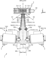
- the manufacturing apparatus 1 includes a pinching section 2 including the pair of nip rolls 21 for conveying the pair of sheets S1 and S2, and the upper elastic member EL and the lower elastic member EL between the pair of sheets S1 and S2. and a pair of elastic member arrangement portions 3 for respectively guiding the members EL.
- the pair of nip rolls 21 nip the pair of sheets S1 and S2 in a state in which the plurality of elastic members EL are interposed between the pair of sheets S1 and S2, while nipping the pair of sheets S1 in the conveying direction. , S2 and the elastic member EL.
- An axis 21a of each of the pair of nip rolls 21 extends parallel to the sheet width direction. Further, the pair of nip rolls 21 are arranged so that their axes 21a are perpendicular to the longitudinal direction of the sheet.
- the direction along the axis 21a of each of the pair of nip rolls 21 is the X direction in FIGS.
- the direction perpendicular to the axis 21a of each of the pair of nip rolls 21 and the direction in which the pair of nip rolls 21 are arranged is the Y direction.
- the Z direction in FIGS. 2 and 3 is orthogonal to the X direction and the Y direction.
- the pinching section 2 includes a nip roll support section 22 and a nip roll motor (not shown).
- the nip roll support portion 22 supports each of the pair of nip rolls 21 so as to be rotatable around the axis 21a.
- the nip roll motor rotates each of the pair of nip rolls 21 about the axis 21a.
- the elastic member arrangement portion 3 for the front waist portion F arranges the plurality of elastic members EL for the front waist portion F (the plurality of upper elastic members EL) among the plurality of elastic members EL on the pair of sheets S1, It guides between S2.
- the elastic member arrangement portion 3 for the rear waist portion B arranges the plurality of elastic members EL (the plurality of lower elastic members EL) for the rear waist portion B among the plurality of elastic members EL on the pair of sheets S1. , S2.
- the pair of elastic member arrangement portions 3 are arranged so as to face each other in the direction (Y direction) in which the axis lines 21a line up with reference to the reference plane CP.
- the reference plane CP is a plane perpendicular to the axial plane AS at the closest point between the pair of nip rolls 21 .
- the axial plane AS is a plane including the axes 21 a of the pair of nip rolls 21 .
- the elastic member arrangement portion 3 for the front waistline portion F is arranged on the left side in FIG. of the elastic member arrangement portion 3 is arranged. Since the pair of elastic member placement portions 3 have the same configuration, the elastic member placement portion 3 for the rear waist portion B will be mainly described below.
- Each elastic member placement section 3 includes a plurality of link members 6a to 6d, a control section 7, and a delivery mechanism 10.
- the feeding mechanism 10 has a guide portion 4 and a moving mechanism 5 .
- the guide part 4 guides the elastic member EL between the pair of sheets S1 and S2 while feeding the elastic member EL such that the longitudinal direction of the elastic member EL is along the feeding direction.
- the guide portion 4 is provided on the upstream side of the pair of nip rolls 21 in the transport direction.
- the delivery direction is a direction (Z direction) from the guide portion 4 toward the pair of nip rolls 21, and is a direction perpendicular to the axis 21a.
- the guide part 4 has a shape extending in a predetermined direction, as shown in FIGS.
- the predetermined direction is a direction perpendicular to the axis 21a in this embodiment.
- the guide portion 4 has a body portion 4b extending in the predetermined direction and a holding portion 4c.
- the holding portion 4c is provided at one end of the body portion 4b, and the other end portion of the body portion 4b is rotatably connected to the plurality of link members 6a to 62 around a guide portion link shaft 62, which will be described later. 6d (guide portion side link member 6b to be described later).
- the body portion 4b is a part of the first rotating member 50 that is rotatable about a guide portion rotating shaft 4a described later between one end and the other end of the body portion 4b. (first guide portion side arm 53 to be described later).
- the holding portion 4c holds the elastic member EL so as to be extended.
- the holding portion 4c extends perpendicularly from one end of the main body portion 4b to the end.
- a parallel link mechanism (attitude maintaining mechanism) including the plurality of link members 6a to 6d is used to move the guide portion 4 so that the holding portion 4c is closer to the nip roll 21 than the moving mechanism 5 is. Posture is maintained. Thereby, the guide portion 4 can always be maintained at a position closer to the nip roll 21 than the moving mechanism 5 is.
- the holding portion 4c of the guiding portion 4 is arranged in a direction (Z direction) perpendicular to the direction in which the pair of axial lines 21a are arranged to guide the plurality of elastic members EL.
- a plurality of holding holes are formed therethrough.
- a plurality of holding holes are provided side by side in the direction along the axis 21a.
- the guide portion 4 guides the plurality of elastic members EL between the pair of sheets S1 and S2 in a state in which each of the elastic members EL is inserted through each of the plurality of holding holes. Therefore, the plurality of elastic members EL are guided between the pair of sheets S1 and S2 in parallel with each other.
- the moving mechanism 5 moves the guide part 4.
- the manner in which the moving mechanism 5 moves the guide portion 4 includes reciprocating movement of the guide portion 4 and retraction movement of the guide portion 4 from the pair of nip rolls 21 .
- the moving mechanism 5 causes the guide section 4 to reciprocate along a preset movement path MP (FIG. 4).
- the moving path MP is a reciprocating path of the guide section 4 set so that the plurality of elastic members EL are arranged on the pair of sheets S1 and S2 along a preset arrangement path.
- the moving path MP extends in a moving direction parallel to the direction (X direction) along the axis 21a.
- the movement path MP is a straight line in this embodiment.
- the moving path MP is included in the moving path plane MS.
- the movement path plane MS is a plane that passes through the holding holes of the holding portion 4c and is inclined with respect to the reference plane CP in a direction away from the reference plane CP as the distance from the pair of nip rolls 21 increases. Further, in the present embodiment, the movement path MP is set such that the distance between the nip point and the movement path MP in the direction orthogonal to the axis 21a is constant over the entire movement path MP.
- the nip point is a position where the plurality of elastic members EL are sandwiched between the pair of sheets S1 and S2 by the pair of nip rolls 21 .
- a straight line parallel to the axis 21a includes a curve substantially parallel to the axis 21a.
- the movement mechanism 5 retracts the guide part 4 from the pair of nip rolls 21 along the direction perpendicular to the axis 21a.
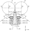
- the moving mechanism 5 of the present embodiment includes a first rotating member 50, a first rotating driving portion 51, a second rotating member 55, and a second rotating member 55. and a dynamic drive 56 .
- the first rotating member 50 is rotatable around a first rotation center shaft 50a and is rotatably connected to the guide portion 4.
- the first rotation member 50 is configured such that a first rotation radius connecting the guide portion 4 and the first rotation center shaft 50a can be varied.
- the first rotation center axis 50a is orthogonal to the movement path plane MS at a position away from the guide section 4 within the movement path plane MS.
- the first rotation drive section 51 rotates the first rotation member 50 around the first rotation center shaft 50a.
- the first rotation driving unit 51 includes a rotating shaft connected to the first rotating member 50, a driving unit (not shown) that rotationally drives the rotating shaft, and a rotation angle of the rotating shaft with respect to the driving unit. and an angle detection unit 14a (see FIG. 2) for detecting the torque generated in the rotating shaft.
- the first rotation driving section 51 is configured by a servomotor.
- the second rotating member 55 is rotatable about a second rotating center shaft 55a, is rotatably connected to the first rotating member 50, and is rotatable with the guide portion 4. connected to The second rotation member 55 is configured such that a second rotation radius connecting the guide portion 4 and the second rotation central shaft 55a can be varied.
- the second rotation center shaft 55a extends parallel to the first rotation center shaft 50a at a position apart from the guide portion 4 in the movement path plane MS.
- the second rotation drive section 56 rotates the second rotation member 55 around the second rotation center shaft 55a.
- the second rotation drive unit 56 includes a rotation shaft connected to the second rotation member 55, a drive unit (not shown) that rotationally drives the rotation shaft, and a rotation angle of the rotation shaft with respect to the drive unit. and an angle detection unit 14b for detecting the torque generated in the rotating shaft.
- the second rotation driving section 56 is configured by a servomotor.
- the rotation of the first rotation member 50 by the first rotation drive section 51 and the rotation of the second rotation member 55 by the second rotation drive section 56 are performed by moving the guide section 4 along the moving path. Synchronization is performed by a reciprocating movement control section 7a, which will be described later, so as to reciprocate along the MP.
- the first rotating member 50 and the second rotating member 55 rotate along the movement path plane MS.
- the first rotating member 50 and the second rotating member 55 have the same configuration. Further, the first rotation driving portion 51 and the second rotation driving portion 56 have the same configuration.
- the positions of the first rotating member 50 and the second rotating member 55 indicated by broken lines correspond to the positions of the first rotating member 50 and the second rotating member 55 when the guide portion 4 is arranged at the center position of the movement path MP. This is the position of the first rotating member 50 and the second rotating member 55 .
- the center position is the center position of the moving path MP in the direction along the axis 21a.
- the first rotation center shaft 50a and the second rotation center shaft 55a extend along the center position center line MM. They are arranged symmetrically as a reference. Further, when the guide portion 4 is positioned at the central position, the first rotating member 50 and the second rotating member 55 are arranged symmetrically with respect to the central position center line MM, and The first rotation driving portion 51 and the second rotation driving portion 56 are arranged symmetrically.
- the first rotating member 50 and the second rotating member 55 will be described in more detail below.
- the first rotating member 50 has a first driven arm 52 and a first guide section side arm 53 that are relatively rotatable with respect to each other.
- the first driven arm 52 is connected to the first rotation driving portion 51 so as to rotate around the first rotation center shaft 50a.
- the first guide portion side arm 53 is rotatably connected to the first driven arm 52 about the first intermediate shaft 50b.
- the first intermediate shaft 50b is provided at a portion of the first driven arm 52 away from the first rotation center shaft 50a and is parallel to the first rotation center shaft 50a.
- the guide portion 4 is rotatably connected to the first guide portion side arm 53 around the guide portion rotating shaft 4a.
- the guide portion rotation shaft 4a is provided at a portion of the first guide portion side arm 53 away from the first intermediate shaft 50b and is parallel to the first rotation center shaft 50a.
- the first driven arm 52 and the first guide side arm 53 have a flat plate shape in this embodiment, and are composed of a rigid body.
- the second rotating member 55 has a second driven arm 57 and a second guide side arm 58 that are relatively rotatable with respect to each other.
- the second driven arm 57 is connected to the second rotation driving portion 56 so as to rotate around the second rotation center shaft 55a.
- the second guide portion side arm 58 is rotatably connected to the second driven arm 57 about the second intermediate shaft 55b.
- the second intermediate shaft 55b is provided at a portion of the second driven arm 57 away from the second rotation center shaft 55a and is parallel to the first rotation center shaft 50a.
- the guide portion 4 is connected to the first guide portion side arm 53 so as to be rotatable about the guide portion rotating shaft 4a. It is rotatably connected to the second guide side arm 58 .
- the guide portion rotation shaft 4a extends parallel to the first rotation central shaft 50a at a portion of the first guide portion side arm 53 away from the first intermediate shaft 50b.
- a portion of the second guide side arm 58 that is apart from the second intermediate shaft 55b extends parallel to the first pivot shaft 50a. That is, the guide portion rotating shaft 4a is parallel to the first intermediate shaft 50b and the second intermediate shaft 55b.
- the second driven arm 57 and the second guide side arm 58 have a flat plate shape in this embodiment, and are composed of a rigid body.
- the movement path MP is positioned within the region where the guide portions 4 provided at the tip portions of the first guide portion side arm 53 and the second guide portion side arm 58 move.
- the distance from the first rotation center shaft 50a to the first intermediate shaft 50b is the same as the distance from the second rotation center shaft 55a to the second intermediate shaft 55b
- the distance from the first intermediate shaft 50b to the guide portion rotation shaft 4a is the same as the distance from the second intermediate shaft 55b to the guide portion rotation shaft 4a. That is, the radius of rotation of the first driven arm 52 and the radius of rotation of the second driven arm 57 are the same, and the radius of rotation of the first guide portion side arm 53 and the radius of rotation of the second guide arm 53 are the same.
- the turning radius of the part side arm 58 is the same.
- the distance between the guide portion rotation shaft 4a and the first intermediate shaft 50b in the direction along the axis 21a is equal to that of the guide portion rotation shaft 4a and the first intermediate shaft 50b. It is longer than the distance from the one-rotation central axis 50a.
- the first intermediate shaft 50b is arranged farther from the central position center line MM than the first pivot shaft 50a in the direction along the axis 21a.
- the distance between the guide portion rotation shaft 4a and the second intermediate shaft 55b is the same as the guide portion rotation shaft 4a and the second rotation center.
- the second intermediate shaft 55b is arranged at a position farther from the central position center line MM than the second rotation center shaft 55a in the direction along the axis 21a.
- the plurality of link members 6a to 6d are arranged to maintain the posture of the guide portion 4 so that the holding portion 4c is positioned closer to the pair of nip rolls 21 than the moving mechanism 5. Together with the arm 52 and the arm 53 on the side of the first guide portion, the parallel link mechanism (attitude maintaining mechanism) is configured.
- the plurality of link members 6a to 6d have a driven link member 6a, the guide portion side link member 6b, an intermediate link member 6c, and a support member 6d.
- the support member 6d supports the first rotation center shaft 50a and the link rotation center shaft 61 so as to restrict relative movement between the first rotation center shaft 50a and the link rotation center shaft 61.
- the link rotation center axis 61 is parallel to the first rotation center axis 50a.
- the link rotation center shaft 61 is supported by the support member 6d at a position away from the first rotation center shaft 50a.
- the direction in which the link rotation center axis 61 moves away from the first rotation center axis 50a is the direction orthogonal to the axis 21a and in the direction away from the pair of nip rolls 21. As shown in FIG.
- the driven link member 6a is supported by the support member 6d so as to be rotatable about the link rotation center shaft 61.
- the guide portion side link member 6b is connected to the guide portion 4 so as to be rotatable about the guide portion link shaft 62, and is rotatable about the first intermediate link shaft 63 with respect to the driven link member 6a.
- connected to The guide portion link shaft 62 is parallel to the first rotation center shaft 50a.
- the first intermediate link shaft 63 is parallel to the first pivot shaft 50a.
- the intermediate link member 6c is supported by the first guide portion side arm 53 so as to be rotatable about the first intermediate shaft 50b, and is mounted relative to the driven link member 6a and the guide portion side link member 6b. It is connected so as to be rotatable around the first intermediate link shaft 63 .
- the plurality of link members 6a to 6d, the first driven arm 52, and the first guide portion side arm 53 form two parallelograms in the present embodiment.
- One of the two parallelograms has a straight line connecting the guide portion rotation shaft 4a and the first intermediate shaft 50b, and the guide portion link shaft 62 and the first intermediate link shaft 63.
- the other parallelogram is defined by a straight line connecting the first pivot shaft 50a and the first intermediate shaft 50b, the link pivot shaft 61 and the first intermediate link shaft 63. , a straight line connecting the first pivot shaft 50a and the link pivot shaft 61, and a straight line connecting the first intermediate shaft 50b and the first intermediate link shaft 63. be done.
- the plurality of link members 6a to 6d face each other across the reference plane CP in each of the pair of elastic member arrangement portions 3 as shown in FIG. Therefore, the pair of elastic member placement portions 3 are inclined in directions away from each other as the distance from the pair of nip rolls 21 increases so that the plurality of link members 6a to 6d of each elastic member placement portion 3 do not contact each other. .
- the control unit 7 controls the movement of the moving mechanism 5 including the reciprocating movement and the retracting movement.
- the control unit 7 includes the reciprocating movement control unit 7a and the retraction movement control unit 7b.
- the reciprocating movement control section 7a controls the rotation of the first rotating member 50 by the first rotation driving section 51 and the second rotation so as to reciprocate the guide section 4 along the movement path MP. Reciprocating movement control is performed in synchronization with the rotation of the second rotating member 55 by the drive unit 56 . Synchronizing the rotation of the first rotating member 50 and the rotation of the second rotating member 55 by the reciprocating movement control unit 7a means that the guide unit 4 is moved along the movement path MP. , the reciprocating movement control unit 7a determines the first turning angle of the first turning member 50 and the second turning angle of the second turning member 55, and the reciprocating movement control unit 7a determines the first turning angle.
- the first rotation angle is a rotation angle about the first rotation center axis 50a, which is a straight line connecting the first rotation center axis 50a and the first intermediate shaft 50b.
- the second rotation angle is a rotation angle around the second rotation center axis 55a, which is a straight line connecting the second rotation center axis 55a and the second intermediate shaft 55b.
- the reciprocating movement control realizes the reciprocating movement of the guide section 4 along the moving path MP.
- the reciprocating movement control will be specifically described as follows. First, in FIG. 4, the positions of the first rotating member 50 and the first rotating driving section 51, and the second rotating member 55 and the second rotating driving section 56 indicated by solid lines are assumed to be the original positions. do.
- the origin position is the position of the moving mechanism 5 and the guide portion 4 when the guide portion 4 is positioned at one end of the movement path MP in the direction (X direction) along the axis 21a. . In this embodiment, the guide portion 4 is located at the leftmost point on the movement path MP at the origin position. In FIG.
- the first rotating member 50 and the first rotating driving portion 51, and the second rotating member 55 and the second rotating driving portion 56 indicated by two-dot chain lines are located at the center of the central position.
- a position arranged symmetrically with respect to the origin position with respect to the line MM is assumed to be a folding position.
- the folding position is the position of the moving mechanism 5 and the guiding portion 4 when the guiding portion 4 is positioned at the other end of the moving path MP in the direction along the axis 21a.
- the guide portion 4 is positioned at the rightmost point on the movement path MP at the turn-back position.
- the reciprocating movement control portion 7a controls the rotation direction of the first rotation member 50 and the rotation direction of the first rotation member 50. 2, the rotating direction of the rotating member 55 is the same. Specifically, the reciprocating movement control unit 7a controls the first rotation angle of the first driven arm 52 in the clockwise direction and the second rotation angle of the second driven arm 57 in the clockwise direction. Decide to change in chronological order. The first rotation angle and the second rotation angle are determined so that the guide part 4 can move along the movement path MP.
- the reciprocating movement control section 7a rotates the first rotation driving section 51 at the first rotation angle in the clockwise direction in chronological order, and rotates the second rotation driving section 56 at the first rotation angle. is rotated in the clockwise direction at the second rotation angle along the time series.
- the first driven arm 52 and the second driven arm 57 are synchronized in a state in which both the first guide portion side arm 53 and the second guide portion side arm 58 are connected to the guide portion 4.
- the relative rotation of the first guide portion side arm 53 with respect to the first driven arm 52 and the relative rotation of the second guide portion side arm 58 with respect to the second driven arm 57 are achieved.
- the guide part 4 can be reciprocated along the moving path MP while being accompanied. In the relative rotation of the first guide portion side arm 53 with respect to the first driven arm 52, the angle formed by the first driven arm 52 and the first guide portion side arm 53 changes, thereby causing the first guide portion side arm 53 to rotate.
- a first distance between the first rotation center shaft 50a and the guide portion rotation shaft 4a changes in the first rotation radial direction. Further, the relative rotation of the second guide portion side arm 58 with respect to the second driven arm 57 causes the second distance between the second rotation center shaft 55a and the guide portion rotation shaft 4a to increase to the second distance. It changes in the rotational radial direction.
- the first distance changes so as to become shorter in the first rotation radial direction
- the second distance changes to the It changes so as to be longer in the second rotation radial direction.
- the reciprocating movement control portion 7a controls the counterclockwise direction of the first driven arm 52. and the second rotation angle of the second driven arm 57 in the counterclockwise direction are changed in time series.
- the reciprocating movement control section 7a rotates the first rotation driving section 51 at the first rotation angle in the counterclockwise direction in chronological order, and rotates the second rotation driving section 51 at the first rotation angle. 56 is rotated in the counterclockwise direction at the second rotation angle in chronological order.
- the first distance is increased in the first rotation radial direction.
- the second distance changes to become shorter in the second rotation radial direction.
- the guide portion 4 is moved along the origin position from the turn-back position of the movement path MP through the center position.
- the rear waist portion B in which the elastic member EL is sandwiched between the pair of sheets S1 and S2 as shown in FIG. 4 is manufactured. be done.
- the retraction movement control section 7b rotates and rotates the first rotating member 50 so as to retract the guide section 4 from the pair of nip rolls 21 along the direction perpendicular to the axis 21a.
- Retreat movement control that synchronizes with the rotation of the second rotating member 55 is performed.
- the retreat movement control is control that is performed outside the period in which the reciprocating movement control is being performed.
- the retraction movement control section 7b synchronizes the rotation of the first rotating member 50 and the rotation of the second rotating member 55 so that the guide section 4 is retracted from the pair of nip rolls 21.
- the retraction movement control section 7b determines the first rotation angle and the second rotation angle, and the retraction movement control section 7b controls the first rotation driving section 51 and the second rotation driving section 56. is controlled based on the first rotation angle and the second rotation angle.
- the retraction movement control is executed when the guide portion 4 exists at the central position as shown in FIG.
- a specific description of the retraction movement control is as follows.
- the retraction movement control part 7b controls the first rotating member 50 and the rotating direction of the second rotating member 55 are made different.
- the retraction movement control unit 7b controls the first rotation angle of the first driven arm 52 in the clockwise direction and the second rotation angle of the second driven arm 57 in the counterclockwise direction. Decide to change the angle in time series.
- the first rotation angle and the second rotation angle in the retraction movement control are determined to be the same.
- the retraction movement control unit 7b rotates the first rotation driving unit 51 at the first rotation angle in the clockwise direction along the time series, and the second rotation driving unit 56 is rotated in the counterclockwise direction at the second rotation angle along the time series.
- the manufacturing apparatus 1 includes a stopper 15 that restricts the clockwise rotation of the first driven arm 52 and a stopper 15 that restricts the counterclockwise rotation of the second driven arm 57. and a regulating stopper 16.
- the retraction movement control section 7b moves the driven arms 52 and 57 to a position (hereinafter referred to as retraction position) where the driven arms 52 and 57 abut against the stoppers 15 and 16. 57 is rotated.
- the distance between the guide part 4 and the pair of nip rolls 21 can be widened. Maintenance of the delivery mechanism 10 can be performed using the interval.
- the elastic laminated body L manufacturing apparatus 1 further includes a storage section 11 and an input operation section 12 electrically connected to the control section 7 .
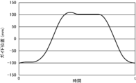
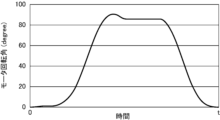
- the storage unit 11 stores different movement patterns (FIG. 9) of the guide unit 4 on the movement path MP according to the specifications of the elastic laminate L (the size of the disposable diaper D in this embodiment). Further, the storage unit 11 stores the driving pattern of the first rotation driving unit 51 set based on the movement pattern of FIG. 9 and the driving pattern of the second rotation driving unit 56 set based on the movement pattern of FIG. , is remembered. These FIGS. 9 and 10 include one cycle pattern for one round trip on the movement path MP.
- the input operation unit 12 performs an operation for inputting a command for selecting one specification from among a plurality of specifications of the elastic laminate L, a command for starting production of the elastic laminate L, and a command for stopping production. Allows operations to enter commands for
- the input operation unit 12 is composed of a touch panel.
- control unit 7 also electrically controls the torque detection units 13a and 13b and the angle detection units 14a and 14b in the first rotation driving unit 51 and the second rotation driving unit 56 described above. It is connected to the.
- the control unit 7 executes processing for manufacturing the elastic laminate L based on information from the storage unit 11, the input operation unit 12, the torque detection units 13a and 13b, and the angle detection units 14a and 14b.
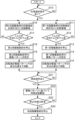
- step S10 when the process by the control unit 7 is started, it waits for the selection operation of the specification of the elastic laminate L (the specification of the disposable diaper D in this embodiment) to be performed.
- step S10 when it is determined that the selection operation of the specification of the elastic laminate L has been performed (YES in step S10), processing for aligning the rotation axis of the first rotary drive unit 51 with the origin (S11 to S15). , and a process (steps S16 to S20) for aligning the rotation axis of the second rotation drive unit 56 with the origin.
- the first rotary drive unit 51 rotates the rotary shaft clockwise (step S11), and the first driven arm 52 comes into contact with the stopper 15 to generate torque. has increased to a predetermined torque (step S12). If it is determined that the torque is less than the predetermined torque based on the detection result of the torque detection unit 13a (NO in step S12), step S11 is continued, and if it is determined that the torque has increased to the predetermined torque ( YES at step S12), and the first rotation drive unit 51 is stopped (step S13). Note that the rotational position of the first rotary drive section 51 thus stopped is stored as a reference position in the storage section 11, and the relative rotation angle from this reference position (the angle detected by the angle detection section 14a).
- step S10 the pattern of the first rotation driving unit 51 is read from the storage unit 11, and set as the pattern for driving this time (step S14).
- the first rotation drive unit 51 is rotationally driven to the set origin position (for example, the position where the "motor rotation angle" is 0 in FIG. 10) (step S15).
- step S16 the rotary shaft is rotated counterclockwise (step S16), and the second driven arm 57 comes into contact with the stopper 16 to check if the torque has increased to a predetermined torque. It is determined whether or not (step S17). If it is determined that the torque is less than the predetermined torque based on the detection result of the torque detection unit 13b (NO in step S17), step S16 is continued, and if it is determined that the torque has increased to the predetermined torque ( YES at step S17), and the second rotation drive unit 56 is stopped (step S18).
- the rotational position of the second rotation drive section 56 thus stopped is stored in the storage section 11 as a reference position, and the relative rotation angle from this reference position is
- the second rotation driving section 56 is controlled so as to achieve the "motor rotation angle" in the driving pattern (for example, the one shown in FIG. 11) based on (the angle detected by the angle detection section 14b).
- the pattern of the second rotation driving section 56 is read from the storage section 11, and set as the current drive pattern (step S19).
- the second rotation drive unit 56 is rotationally driven to the set origin position (for example, the position where the "motor rotation angle" is 0 in FIG. 11) (step S20).
- the input operation unit 12 performs an operation to start manufacturing the elastic laminate L. It waits until it is finished (step S21).
- both rotary drive units 51 and 56 are synchronously rotated based on the drive patterns set in steps S14 and S19 (step S22). .
- the control unit 7 controls both rotations along a common time axis using two drive patterns (for example, those shown in FIGS. 10 and 11) for both rotation drives 51 and 56. It controls driving of the drive units 51 and 56 . 10 and 11, the drive pattern for one cycle for one reciprocation of the movement path is set, and the control unit 7 outputs the same drive pattern when one cycle of a specific drive pattern is completed. Repeat from the beginning.
- step S23 it is determined whether or not the preset stop time has arrived.
- the stop time may be automatically generated according to the input of the start operation described above, or may be manually input by the input operation unit 12 . Until the stop time comes (while step S23 is NO), the synchronous rotational drive is continued (step S22).
- step S23 when it is determined that the stop time has come (YES in step S23), both rotation drive units 51 and 56 are stopped (step S24), and the process ends.
- the elastic member placement portion 3 for the front waistline portion F shown in FIG. 5 is the elastic member placement portion 3 for the back waistline portion B shown in FIGS. It has the same configuration as the member placement portion 3 .
- the elastic member EL for the front waist portion F is placed in the front waist portion F by the same procedure as the elastic member placement portion 3 for the back waist portion B. .
- the distance of the movement path for moving the guide portion 4 in the elastic member placement portion 3 for the front waist portion F is the distance for moving the guide portion 4 in the elastic member placement portion 3 for the rear waist portion B. Different from the distance of the path MP.
- the length of the movement path of the guide portion 4 is longer than the length of the movement path MP of the elastic member arrangement portion 3 for the rear waistline portion B. is set short.
- the reciprocating movement control section 7a sets the maximum angle of the first rotation angle and the maximum angle of the second rotation angle to be smaller than when the rear waist portion B is manufactured.
- the method for manufacturing the elastic laminate L includes (1) a manufacturing apparatus preparation step, (2) a sheet conveying step, (3) an elastic member placement step, and (4) a retreating step.
- the pair of sheets S1 and S2 is prepared, and the pair of nip rolls 21 sandwiches the ends of the pair of sheets S1 and S2 in the sheet longitudinal direction. Specifically, as shown in FIG. 2, the sheet S1 is placed from one side of the pair of nip rolls 21, and the sheet S2 is placed from the other side of the pair of nip rolls 21 between the pair of nip rolls 21. Sandwich.
- a pair of a plurality of elastic members EL are guided through the pair of elastic member arrangement portions 3 .
- Each of the pair of plurality of elastic members EL is guided to the guide portion 4 of each of the pair of elastic member placement portions 3 .
- Each of the plurality of elastic members EL is inserted through each of the plurality of holding holes of the holding portion 4 c in the guide portion 4 .
- the reciprocating movement control section 7a rotates the first rotating member 50 by the first rotating driving section 51 and the first rotating member 50 so as to reciprocate the guide section 4 along the moving path MP.
- the rotation of the second rotating member 55 by the two-rotation driving unit 56 is synchronized.
- the plurality of elastic members EL are moved from the guide portion 4 between the pair of sheets S1 and S2 in the longitudinal direction of the plurality of elastic members EL. feed out.
- the elastic laminate L is manufactured by conveying the plurality of elastic members EL interposed between the pair of sheets S1 and S2 while being sandwiched between the pair of nip rolls 21 .
- the plurality of link members 6a to 6d allow the guide portion 4 to move along the movement path MP while maintaining the posture. Specifically, it is as follows. In the parallel link mechanism, the first rotation center shaft 50a and the link rotation center shaft 61 are supported by the support member 6d in a state in which relative movement is restricted. As a result, the posture of the guide portion 4 during the period of movement of the guide portion 4 by the moving mechanism 5, that is, the orientation of the line connecting the guide portion rotation shaft 4a and the guide portion link shaft 62 is changed from the The direction of the line connecting the first rotation center axis 50a and the link rotation center axis 61 is maintained in the same direction. In other words, the guide portion 4 can be moved along the movement path MP while maintaining the posture corresponding to the directions of these straight lines.
- the moving path MP has a constant distance in the feeding direction (direction orthogonal to the axis 21a) between the nip point and the moving path MP over the entire moving path MP. is set to
- the movement path MP moves the guide part 4 extra according to the distance from the guide part 4 to the nip point.
- the distance between the guide portion 4 and the nip point is equal to the distance between the guide portion 4 and the nip point after the predetermined portion of the elastic member EL is let out from the guide portion 4 until the predetermined portion actually reaches the nip point.
- the turning radius of the first driven arm 52 and the turning radius of the second driven arm 57 are the same, and the turning radius of the first guide portion side arm 53 is the same. and the rotation radius of the second guide portion side arm 58 are the same, the center in the direction along the axis 21a between the first rotation center shaft 50a and the second rotation center shaft 55a
- the operations of the first rotation driving section 51 and the second rotation driving section 56 are performed as described above. Since they can be set symmetrically with respect to the center position, it is possible to simplify the arithmetic processing when synchronizing the rotation of the first rotation drive section 51 and the rotation of the second rotation drive section 56 .
- an adhesive may be applied to at least one of the pair of sheets S1 and S2 and the plurality of elastic members EL. Further, the pair of sheets S1 and S2 and the plurality of elastic members EL are separated by applying heat to the elastic laminate L with the plurality of elastic members EL interposed between the pair of sheets S1 and S2. It can be welded. Heat may be applied, for example, by the pair of nip rolls 21 that are heated, or by ultrasonically vibrating the pair of nip rolls.
- the guide section 4 can be reciprocated along the movement path MP without using a regulation mechanism that involves sliding friction of the slider against the rail. This can reduce maintenance frequency.
- the guide portion 4 is moved along the movement path MP.
- the moving mechanism 5 By controlling the moving mechanism 5 so that the rotation by the rotation drive section 51 and the rotation by the second rotation drive section 56 are synchronized, the first rotation of the first rotation member 50 is controlled.
- the guide part 4 can be reciprocated along the movement path MP while changing the radius and the second turning radius of the second turning member 55 .
- the regulation mechanism can be omitted, and the frequency of maintenance due to the existence of the regulation mechanism can be reduced.
- the guide portion 4 can be reciprocated compared to the conventional case where the guide portion 4 is reciprocated by reciprocating the belt stretched over a pair of pulleys so as to repeat the reversal of the moving direction. Since the sliding resistance of the moving mechanism at this time is small, the moving speed of the guide portion 4 can be increased, and the manufacturing speed of the elastic laminate L can be increased.
- the configuration is not limited to a configuration in which a plurality of arms are connected.
- the first rotating member and the second rotating member of the present invention are configured by an extendable member, for example, a telescopic member. good too.
- a telescopic member is composed of two members, for example, a receiving member and a received member. The telescopic member can be expanded and contracted by being configured so that the member to be stored can be pulled out or stored in the storage member.
- the first rotating member has a first storage member and a first stored member that is connected to the first storage member so that it can be drawn out or stored.
- the second rotating member has a second storage member and a second stored member connected to the second storage member so that it can be pulled out or stored.
- the first housing member is connected to the first pivot shaft.
- the first stored member is connected to the guide portion.
- the second storage member is connected to the second rotation center shaft.
- the second stored member is connected to the guide portion. In a state in which both the first member to be stored and the second member to be stored are connected to the guide portion, the first member to be stored rotates about the first rotation center axis, and the second member to be stored rotates.
- the first member to be stored is pulled out or stored with respect to the first member to be stored, and the second member to be stored is moved to the second storage. Drawn out or retracted with respect to the member. Thereby, the first distance and the second distance change so as to move the guide part along the movement path.
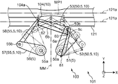
- a manufacturing apparatus 101 shown in FIG. 12 includes a pair of nip rolls 121 having an axis 121a and a pair of elastic member arrangement portions 103.
- Each elastic member placement section 103 includes a plurality of link members 6 a to 6 d, a control section 7 and a delivery mechanism 10 .
- the delivery mechanism 10 has a guide portion 104 and a moving mechanism 5 .
- the guide portion 104 has a different configuration from the guide portion 4 of the above embodiment, the moving mechanism 5, the plurality of link members 6a to 6d, and the control portion 7 have the same configurations as those of the above embodiment.
- the elastic member arranging portion 103 is arranged on the pair of nip rolls 121 so that the first rotation center axis 50a of the first rotation member 50 of the moving mechanism 5 extends in a direction orthogonal to the direction in which the pair of axis lines 21a are arranged. placed opposite.
- the guide part 104 guides the plurality of elastic members EL toward the pair of nip rolls 121 .
- the guide portion 104 includes a first main body portion 104b extending along the axial plane AS1 and a first body portion 104b extending from the first main body portion 104b toward the pair of nip rolls 121 in a direction perpendicular to the axial plane AS1. It has two body portions 104d and a holding portion 104c provided at the end portion of the second body portion 104d near the pair of nip rolls 121 .
- the holding portion 104c extends from the second body portion 104d in a direction orthogonal to the second body portion 104d.
- the axial plane AS1 is a plane including the pair of axial lines 121a and extends in a direction orthogonal to the axial lines 21a.
- the first rotation center shaft 50a in FIG. 12 extends in a direction orthogonal to the direction in which the pair of axis lines 21a are arranged, that is, orthogonal to the axial plane AS1.
- the second rotation center axis is also perpendicular to the axial plane AS1.
- the first rotating member 50 and the second rotating member rotate along the axial plane AS1.
- the holding portion 104c also rotates along the axial plane AS1. Therefore, the moving path of the holding portion 104c is along the axial plane AS1.
- the plurality of elastic members are guided between the pair of sheets by the movement of the guide portion 104 along the movement path.
- the movement path is not limited to a straight line parallel to the axis, and may be a curved line.
- the trajectory of the nip points may be curved along the axial direction, and the moving path may be curved along the axial direction as well as the trajectory of the nip points.
- the aspect in which the movement path and the trajectory of the nip point are curved can be realized by curving the outer surfaces of the pair of nip rolls 121 in the manufacturing apparatus 101 shown in FIG. This will be described below with reference to FIG. 13 together with FIG.
- the outer surfaces of the pair of nip rolls 121 of the manufacturing apparatus 101 shown in FIG. 12 can be curved as shown in FIG. Specifically, as shown in FIG. 13, the outer surface of one nip roll 121 (the lower nip roll 121 in FIG. 13) of the pair of nip rolls 121 is convex along the axis 121a of the one nip roll 121. is curved. The outer surface of the other nip roll 121 (the upper nip roll 121 in FIG. 13) of the pair of nip rolls 121 is aligned along the axis 121a of the other nip roll 121 so as to mesh with the outer surface of the one nip roll 121.
- the pair of nip rolls 121 can sandwich the pair of sheets S1 and S2 and the plurality of elastic members EL by the convex outer surface of one nip roll 121 and the concave outer surface of the other nip roll 121. be.
- the guide part 104 feeds out the plurality of elastic members EL while moving along the curved movement path MP1.
- the curved movement path MP1 is a movement path of the guide portion 104. As shown in FIG.
- the curved movement path MP1 is set so as to curve along the direction in which the axis 121a extends in accordance with the curved shape of the pair of nip rolls 121. As shown in FIG. In the example of FIG. 13, the curved movement path MP1 is curved in an arc shape.
- the plurality of elastic members EL drawn out from the guide portion 104 are guided between the pair of sheets S1 and S2.
- the pair of sheets S1 and S2 and the plurality of elastic members EL are conveyed while being sandwiched between the pair of nip rolls 121 while being curved in the direction in which the axis 121a extends.
- the trajectory of the nip points of the plurality of elastic members EL is curved in the direction in which the axis 121a extends in accordance with the curved shape of the pair of nip rolls 121.
- the distance between the curved movement path MP1 and the nip point in the direction orthogonal to the axis 121a is constant over the direction in which the axis 121a extends.
- the reciprocating movement control section 7a controls the moving mechanism 5 so that the guide section 104 reciprocates along the curved movement path MP1.
- the movement path is not limited to linear and arc-shaped paths, and may be paths of various shapes. That is, the guide portion located at the tip of the first guide arm and the second guide arm is rotated by the first rotation drive portion and the second rotation drive portion.
- the movement path can be arbitrarily set within a movable area by synchronization with the rotation of the second rotation member by the reciprocating movement control unit.
- the distance between the nip point and the moving path in the direction perpendicular to the axis is necessarily constant over the direction in which the axis extends. , and the distance may vary along the direction in which the axis extends.
- the trajectory of the nip point may be curved in the direction in which the axis extends, and the moving path may be straight in the direction in which the axis extends.
- the trajectory of the nip point may be straight in the direction in which the axis extends, and the moving path may be curved in the direction in which the axis extends.
- the posture maintaining mechanism of the present invention is not limited to the parallel link mechanism, and may be, for example, a correction mechanism that corrects the posture of the guide section.
- the correction mechanism detects, for example, a deviation in the predetermined direction in which the guide part 4 extends with respect to a direction perpendicular to the axis, and corrects the deviation to maintain the posture of the guide part. rotate.
- the plurality of link members of the present invention are not limited to the aspect provided in the first rotating member and the first rotating drive section, and may also be provided in the second rotating member and the second rotating drive section. may be provided.
- the pair of elastic member placement portions 203 unlike the elastic member placement portion 3 shown in FIGS. 2 and 3, the plurality of link members 6a to 6d are omitted. Since a space for providing the plurality of link members 6a to 6d is not required between the pair of elastic member arrangement portions 3, the pair of elastic member arrangement portions 3 are arranged so as to be close to each other. ing.
- the guiding part 4 and the moving mechanism 5 are configured as separate members in the feeding mechanism, but the structure of the feeding mechanism is not limited to this.
- the moving mechanism and the guide section may be integrated.
- the guide portion may be configured by a holding hole provided in a connecting portion between the first guide portion side arm and the second guide side arm. The elastic member is inserted through the holding hole, and the elastic member is guided between the pair of sheets through the holding hole.
- the guide part of the present invention is not limited to the shape of the above embodiment as long as it has a shape that can guide the plurality of elastic members between the pair of sheets.
- it may be a circular, elliptical, or spherical member that does not extend in the delivery direction and is rotatably attached to the guide portion rotating shaft.
- the plurality of elastic members are not limited to being arranged on a pair of sheets, and only one elastic member may be arranged.
- An elastic laminate manufacturing apparatus for solving the above problems is an apparatus for manufacturing an elastic laminate including a pair of sheets extending in the longitudinal direction and an elastic member sandwiched between the pair of sheets, The respective axes are arranged such that the pair of sheets and the elastic member are conveyed in a conveying direction parallel to the longitudinal direction while sandwiching the pair of sheets with the elastic member interposed between the pair of sheets. a pair of nip rolls arranged perpendicular to the longitudinal direction; and a pair of nip rolls arranged upstream of the pair of nip rolls in the conveying direction, and the longitudinal direction of the elastic member is along the delivery direction perpendicular to the axis.
- a moving mechanism capable of reciprocating the guiding portion in a moving direction parallel to the axis; and the guiding.
- a reciprocating movement control unit that controls the moving mechanism so that the unit reciprocates along the moving path extending in the moving direction, the moving mechanism moving the guiding part in a moving path plane including the moving path and a first turning radius connecting the guide portion and the first turning center axis can be changed.
- a first rotation driving unit configured to rotate the first rotation member around the first rotation center axis; and the guide in the movement path plane.
- an elastic laminated body manufacturing apparatus that performs reciprocating movement control for synchronizing the rotation of a first rotation member and the rotation of the second rotation member by the second rotation drive section.
- a method for manufacturing an elastic laminated body for solving the above-described problems is a method for manufacturing an elastic laminated body using the above-described elastic laminated body manufacturing apparatus, comprising: preparing the elastic laminated body manufacturing apparatus; conveying the pair of sheets in the conveying direction so as to be guided between a pair of nip rolls; a step of synchronizing the rotation of the moving member and the rotation of the second rotation member by the second rotation driving section; and the pair of nip rolls sandwiching the elastic member between the pair of sheets. and guiding the elastic member between the pair of sheets while extending the elastic member in the longitudinal direction of the elastic member using the guide portion.
- the guide portion can be reciprocated along the movement path without using a regulation mechanism that involves sliding friction of the slider with respect to the rail. This can reduce maintenance frequency.
- the first rotation driving unit moves the guide unit along the moving path.
- the movement mechanism so that the rotation by the second rotation driving unit is synchronized with the rotation by the second rotation driving unit, the change in the first rotation radius of the first rotation member and the second rotation
- the guide portion can be reciprocated along the movement path while the second turning radius of the moving member is changed.
- the regulation mechanism can be omitted, and the frequency of maintenance due to the existence of the regulation mechanism can be reduced.
- the reciprocating movement of the guide portion is faster. Since the sliding resistance of the moving mechanism is small, it is possible to increase the moving speed of the guide portion, thereby improving the manufacturing speed of the elastic laminate.
- connection between the first rotating member and the second rotating member may be a direct connection, or may be an indirect connection via a separate intervening member.
- the guide section has a shape extending in a predetermined direction, and a holding section that holds the elastic member so as to be extended is provided at a tip end portion of the guide section in the predetermined direction. It is preferable to further include an attitude maintaining mechanism that maintains the attitude of the guide part so that the holding part is closer to the nip roll than the moving mechanism.
- the guide section can always be maintained at a position closer to the nip roll than the moving mechanism.
- the first rotating member includes a first driven arm connected to the first rotating driving section so as to rotate about the first rotating central axis. and a first guide portion rotatably connected to a portion of the first driven arm away from the first center axis of rotation about a first intermediate shaft parallel to the first center axis of rotation.
- the second rotating member includes a second driven arm coupled to the second rotating drive unit so as to rotate about the second rotation center axis; a second guide side arm rotatably connected to a portion of the second driven arm spaced apart from the second central axis of rotation about a second intermediate axis parallel to the first central axis of rotation; , wherein a portion of the first guide portion side arm separated from the first intermediate shaft and a portion of the second guide portion side arm separated from the second intermediate shaft are parallel to both intermediate shafts.
- the guide portion is rotatably connected about the guide portion rotating shaft, and the guide portion rotates about the guide portion rotating shaft with respect to the first guide portion side arm and the second guide portion side arm. It is preferable to be provided in such a way that the
- the synchronous rotation of the first driven arm and the second driven arm results in the relative rotation of the first guide portion side arm with respect to the first driven arm and the second driven arm.
- the guide portion can be reciprocated along the movement path while the second guide portion side arm is rotated relative to the drive arm.
- the angle formed by the first driven arm and the first guide side arm changes to change the first rotation center.
- a first distance between the shaft and the guide pivot axis varies in the first pivot radial direction.
- the second distance between the second rotation central axis and the guide section rotation axis is increased in the second rotation radial direction by relative rotation of the second guide section side arm with respect to the second driven arm. change to
- the guide section has a shape extending in a predetermined direction, and a holding section that holds the elastic member so as to be extended is provided at a tip end portion of the guide section in the predetermined direction.
- a parallel link mechanism for maintaining the posture of the guide portion so that the holding portion is closer to the nip roll than the moving mechanism is provided by the first driven arm and the first guide portion side arm. It is preferable to further comprise a plurality of link members configured together.
- the guide section can always be maintained at a position closer to the nip roll than the moving mechanism.
- the plurality of link members restrict relative movement between the first rotation center axis and a link rotation center axis parallel to the first rotation center axis.
- a support member that supports the first rotation center shaft and the link rotation center shaft; and a driven link member that is supported by the link rotation center shaft in a rotatable state about the link rotation center shaft.
- an intermediate link member and a guide portion side link member that are rotatably connected to the driven link member about a first intermediate link shaft parallel to the first rotation center axis; The member is supported by the first intermediate shaft so as to be rotatable about the first intermediate shaft, and the guide portion side link member is rotatable about the guide portion link shaft parallel to the first rotation central axis.
- a parallelogram is preferably formed by a straight line connecting the first intermediate axis and the first intermediate link axis.
- the plurality of link members allow the guide portion to move along the movement path while maintaining the posture. Specifically, it is as follows.
- a parallel link mechanism defined by two parallelograms
- the first rotation center shaft and the link rotation center shaft are supported by the support member in a state in which relative movement is restricted.
- the orientation of the guide portion during the period of movement of the guide portion by the moving mechanism that is, the direction of the line connecting the guide portion rotation axis and the guide portion link shaft is the first rotation center axis. and the link rotation center axis. That is, it is possible to move the guide portion along the movement path while maintaining the posture according to the directions of these straight lines.
- the distance from the first rotation center axis to the first intermediate axis is the same as the distance from the second rotation center axis to the second intermediate axis, Moreover, it is preferable that the distance from the front first intermediate shaft to the guide portion rotating shaft and the distance from the second intermediate shaft to the guide portion rotating shaft are the same.
- the turning radius of the first driven arm and the turning radius of the second driven arm are the same, and the turning radius of the first guide portion side arm and the turning radius of the second driven arm are the same. Since the rotation radii of the two guide portion side arms are the same, the above-mentioned
- the operations of the first rotation driving section and the second rotation driving section can be set symmetrically with respect to the center position. Arithmetic processing for synchronizing the rotation of the first rotation drive section and the rotation of the second rotation drive section can be simplified.
- the guiding section is retracted from the pair of nip rolls along the feeding direction except for a period during which the reciprocating movement control is performed by the reciprocating movement control section. It is preferable to further include a retraction movement control section that performs retraction movement control for synchronizing the rotation of the first rotating member and the rotation of the second rotating member.
- the distance between the guide section and the pair of nip rolls can be widened by retracting the guide section from the pair of nip rolls. Maintenance of the feeding mechanism can be performed using the interval.
- the moving path is a nip point at which the elastic member is sandwiched between the pair of sheets by the pair of nip rolls, and the feed between the moving path and the nip point.
- the directional distance is set to be constant throughout the movement path.
- the movement path should be set so as to move the guide part extra according to the distance from the guide part to the nip point.
- the distance between the guide portion and the nip point is adjusted.
- a time difference occurs. Therefore, in order to dispose the elastic member at the desired nip point, it is necessary to move the guide portion in advance in the movement direction in consideration of the time difference.
- the time difference varies depending on the position of the guide section, so complicated calculations are required to set or change the movement path. Become. According to the above manufacturing apparatus, since the distance in the feed-out direction between the nip point and the moving path is constant over the entire moving path, the time difference becomes constant and the calculation for setting the moving path is performed. Easy.
- the moving path is a straight line parallel to the axis.
Landscapes
- Health & Medical Sciences (AREA)
- Engineering & Computer Science (AREA)
- Vascular Medicine (AREA)
- Epidemiology (AREA)
- Biomedical Technology (AREA)
- Heart & Thoracic Surgery (AREA)
- Manufacturing & Machinery (AREA)
- Life Sciences & Earth Sciences (AREA)
- Animal Behavior & Ethology (AREA)
- General Health & Medical Sciences (AREA)
- Public Health (AREA)
- Veterinary Medicine (AREA)
- Absorbent Articles And Supports Therefor (AREA)
- Transmission Devices (AREA)
Abstract
Description
製造装置準備工程では、前記製造装置1を準備する。
シート搬送工程では、シートS1、S2の搬送経路に設けられた図外の駆動ローラを回転駆動するとともに、前記一対のニップロール21を回転駆動することにより前記一対のシートS1、S2を前記搬送方向に搬送する。
弾性部材配置工程では、前記一対のシートS1、S2の間に前記複数の弾性部材ELを案内し、前記一対のシートS1、S2の間に前記複数の弾性部材ELが挟み込まれた前記弾性積層体Lを製造する。
退避工程では、まず前記案内部4を前記中央位置に移動する。次に、前記案内部4を前記軸線21aと直交する方向に沿って前記一対のニップロール21から退避させるように前記退避移動制御部7bにより前記第1回動部材50の回動と前記第2回動部材55の回動とを同期する。
本発明の前記第1回動部材及び前記第2回動部材それぞれは、前記第1回動中心軸回り及び前記第2回動中心軸回りの回動に応じて前記第1距離及び前記第2距離が変わる態様であれば、複数のアームの連結により構成される態様に限定されない。回動に応じて前記第1距離及び前記第2距離が変わる態様として、本発明の前記第1回動部材前記第2回動部材は伸縮可能な部材、例えばテレスコピック型の部材から構成されていてもよい。テレスコピック型の部材は例えば収納部材及び被収納部材を含む2つの部材から構成されている。前記テレスコピック型の部材は、前記収納部材に対して前記被収納部材を引き出し又は収納可能に構成されていることにより伸縮可能である。
本発明の前記第1回動中心軸及び前記第2回動中心軸は、上記実施形態では、前記一対の軸線21aの並ぶ方向(Y方向)に沿って延びる。つまり、上記実施形態の前記第1回動中心軸50a及び前記第2回動中心軸55aは、図2に示すように前記軸線平面ASに平行である。しかし、本発明の前記第1回動中心軸及び前記第2回動中心軸は、前記一対の軸線21aの並ぶ方向と直交する方向(Z方向)に延びてもよい。これについて図12を用いて以下に説明する。
前記移動経路は前記軸線と平行な直線に限定されず、曲線であってもよい。例えば、前記ニップ点の軌跡が前記軸線方向に亘り湾曲しており、前記移動経路が前記ニップ点の軌跡と同様に前記軸線方向に亘り湾曲していてもよい。
前記移動経路は、前記ニップ点と前記移動経路との間の前記軸線と直交する方向の距離が前記軸線が延びる方向に亘り必ずしも一定となる態様に限定されず、当該距離が前記軸線が延びる方向に亘り変化していてもよい。例えば、前記ニップ点の軌跡が前記軸線が延びる方向に亘り湾曲しており、前記移動経路が前記軸線が延びる方向に亘り直線であってもよい。逆に、前記ニップ点の軌跡が前記軸線が延びる方向に亘り直線であり、前記移動経路が前記軸線が延びる方向に亘り湾曲していてもよい。
本発明の前記姿勢維持機構は、前記平行リンク機構に限定されず、例えば、前記案内部の前記姿勢を補正する補正機構であってもよい。前記補正機構は、例えば、前記軸線と直交する方向に対する前記案内部4が延びる前記所定方向のずれを検出するとともに前記ずれを補正することにより前記案内部の前記姿勢を維持するように前記案内部を回動させる。
また、本発明の前記案内部の姿勢を常に前記所定方向に維持できるのであれば、あるいは、前記案内部の姿勢が変化したとしても前記弾性部材の軌跡に大きく影響しなければ、図14及び図15に示す製造装置201の弾性部材配置部203のように、前記複数のリンク部材を省略することができる。
上記実施形態では、前記繰り出し機構において、前記案内部4と前記移動機構5とが別体の部材により構成されているが、前記繰り出し機構の構成は、これに限定されない。例えば、本発明の前記繰り出し機構において前記移動機構と前記案内部とが一体に構成されていてもよい。例えば、前記第1案内部側アームと前記第2案内側アームとの連結部分に設けられた保持穴により案内部が構成されていてもよい。この保持穴には前記弾性部材が挿通されるとともに、この保持穴を介して前記一対のシート間に前記弾性部材が案内される。
本発明において少なくとも前記往復移動制御を実行できればよく、前記退避移動制御は省略されてもよい。
本発明の前記製造装置において、一対のシートには前記複数の弾性部材が配置されることに限定されず、1本の弾性部材のみが配置されてもよい。
Claims (10)
- 長手方向に延びる一対のシートと前記一対のシートの間に挟み込まれる弾性部材とを備える弾性積層体を製造するための装置であって、
前記一対のシート同士の間に前記弾性部材が介在した状態で前記一対のシートを挟み込みながら前記長手方向と平行な搬送方向に前記一対のシート及び前記弾性部材を搬送するように、それぞれの軸線が前記長手方向と直交する状態で配置された一対のニップロールと、
前記搬送方向における前記一対のニップロールの上流側に設けられているとともに前記弾性部材の長手方向が前記軸線と直交する繰り出し方向に沿うように前記弾性部材を繰り出しつつ前記一対のシート間に案内する案内部と、前記案内部を前記軸線と平行な移動方向に往復移動させることが可能な移動機構と、を有する繰り出し機構と、
前記案内部が前記移動方向に延びる移動経路に沿って往復移動するように前記移動機構を制御する往復移動制御部と、を備え、
前記移動機構は、前記移動経路を含む移動経路平面内において前記案内部から離れた位置で前記移動経路平面と直交する第1回動中心軸の回りに回動可能であり、前記案内部と前記第1回動中心軸とを結ぶ第1回動半径が変化可能となるように構成されている第1回動部材と、前記第1回動部材を前記第1回動中心軸の回りに回動させる第1回動駆動部と、前記移動経路平面内において前記案内部から離れた位置で前記第1回動中心軸と平行な第2回動中心軸の回りに回動可能であり、前記第1回動部材と互いに回動可能に連結されており、さらに前記案内部と前記第2回動中心軸とを結ぶ第2回動半径が変化可能となるように構成されている第2回動部材と、前記第2回動部材を前記第2回動中心軸の回りに回動させる第2回動駆動部と、を有し、
前記往復移動制御部は、前記案内部を前記移動経路に沿って往復移動させるように前記第1回動駆動部による前記第1回動部材の回動と前記第2回動駆動部による前記第2回動部材の回動とを同期させる往復移動制御を行う、弾性積層体の製造装置。 - 請求項1に記載の弾性積層体の製造装置であって、
前記案内部が所定方向に延びる形状を有し、前記案内部の前記所定方向の先端部には、前記弾性部材を繰出し可能に保持する保持部が設けられており、
前記保持部が前記移動機構よりも前記ニップロールに近い位置となるように前記案内部の姿勢を維持する姿勢維持機構をさらに備える、弾性積層体の製造装置。 - 請求項1に記載の弾性積層体の製造装置であって、
前記第1回動部材は、前記第1回動中心軸の回りに回動するように前記第1回動駆動部に連結された第1被駆動アームと、前記第1被駆動アームにおける前記第1回動中心軸から離れた部分に対し前記第1回動中心軸と平行な第1中間軸の回りに回動可能に連結された第1案内部側アームと、を有し、
前記第2回動部材は、前記第2回動中心軸の回りに回動するように前記第2回動駆動部に連結された第2被駆動アームと、前記第2被駆動アームにおける前記第2回動中心軸から離れた部分に対し前記第1回動中心軸と平行な第2中間軸の回りに回動可能に連結された第2案内部側アームと、を有し、
前記第1案内部側アームにおける前記第1中間軸から離れた部分と、前記第2案内部側アームにおける前記第2中間軸から離れた部分とが、両中間軸と平行な案内部回動軸回りに回動可能に連結されているとともに、前記案内部は、前記第1案内部側アーム及び前記第2案内部側アームに対して前記案内部回動軸回りに回動可能に設けられている、弾性積層体の製造装置。 - 請求項3に記載の弾性積層体の製造装置であって、
前記案内部が所定方向に延びる形状を有し、前記案内部の前記所定方向の先端部には、前記弾性部材を繰出し可能に保持する保持部が設けられており、
前記保持部が前記移動機構よりも前記ニップロールに近い位置となるように前記案内部の姿勢を維持するための平行リンク機構を前記第1被駆動アーム及び前記第1案内部側アームとともに構成する複数のリンク部材をさらに備える、弾性積層体の製造装置。 - 請求項4に記載の弾性積層体の製造装置であって、
前記複数のリンク部材は、
前記第1回動中心軸及び前記第1回動中心軸と平行なリンク回動中心軸との相対移動を規制するように前記第1回動中心軸及び前記リンク回動中心軸を支持する支持部材と、
前記リンク回動中心軸回りに回動可能な状態で前記リンク回動中心軸に支持された被駆動リンク部材と、
前記被駆動リンク部材に対して前記第1回動中心軸と平行な第1中間リンク軸回りに回動可能に連結された中間リンク部材及び案内部側リンク部材と、を備え、
前記中間リンク部材は、前記第1中間軸回りに回動可能に前記第1中間軸に支持され、
前記案内部側リンク部材は、前記第1回動中心軸と平行な案内部リンク軸回りに回動可能に前記案内部に連結され、
前記案内部回動軸と前記第1中間軸とを結ぶ直線と、前記案内部リンク軸と前記第1中間リンク軸とを結ぶ直線と、前記案内部回動軸と前記案内部リンク軸とを結ぶ直線と、前記第1中間軸と前記第1中間リンク軸とを結ぶ直線と、により平行四辺形が形成されるとともに、前記第1回動中心軸と前記第1中間軸とを結ぶ直線と、前記リンク回動中心軸と前記第1中間リンク軸とを結ぶ直線と、前記第1回動中心軸と前記リンク回動中心軸とを結ぶ直線と、前記第1中間軸と前記第1中間リンク軸とを結ぶ直線と、により平行四辺形が形成される、弾性積層体の製造装置。 - 請求項3~5のいずれか1項に記載の弾性積層体の製造装置であって、
前記第1回動中心軸から前記第1中間軸までの距離と前記第2回動中心軸から前記第2中間軸までの距離とが同一であり、かつ、前前記第1中間軸から前記案内部回動軸までの距離と前記第2中間軸から前記案内部回動軸までの距離とが同一である、弾性積層体の製造装置。 - 請求項1~6のいずれか1項に記載の弾性積層体の製造装置であって、
前記往復移動制御部により前記往復移動制御が行われている期間以外において、前記案内部を前記繰り出し方向に沿って前記一対のニップロールから退避させるように前記第1回動部材の回動と前記第2回動部材の回動とを同期させる退避移動制御を行う退避移動制御部をさらに備える、弾性積層体の製造装置。 - 請求項1~7のいずれか1項に記載の弾性積層体の製造装置であって、
前記移動経路は、前記一対のニップロールにより前記一対のシートの間に前記弾性部材が挟みこまれる位置であるニップ点と前記移動経路との間の前記繰り出し方向の距離が前記移動経路の全体にわたり一定となるように設定されている、弾性積層体の製造装置。 - 請求項1~8のいずれか1項に記載の弾性積層体の製造装置であって、
前記移動経路は、前記軸線と平行な直線である、弾性積層体の製造装置。 - 請求項1~9のいずれか1項に記載の弾性積層体の製造装置を用いた弾性積層体を製造する方法であって、
前記弾性積層体の製造装置を準備する工程と、
前記一対のニップロール間に導かれるように前記一対のシートを前記搬送方向に搬送する工程と、
前記案内部を前記移動経路に沿って往復移動させるように前記第1回動駆動部による前記第1回動部材の回動と前記第2回動駆動部による前記第2回動部材の回動とを同期させる工程と、
前記一対のニップロールにより前記一対のシート同士の間に前記弾性部材が挟みこまれるように、前記案内部を用いて前記弾性部材を前記弾性部材の長手方向に繰り出しつつ前記一対のシート間に案内する工程と、
を備える、弾性積層体の製造方法。
Priority Applications (4)
| Application Number | Priority Date | Filing Date | Title |
|---|---|---|---|
| CN202280052396.7A CN117881541A (zh) | 2021-07-27 | 2022-07-27 | 弹性层叠体的制造装置及制造方法 |
| US18/292,117 US20240359448A1 (en) | 2021-07-27 | 2022-07-27 | Manufacturing device and manufacturing method for elastic laminate |
| EP22849528.9A EP4360878A4 (en) | 2021-07-27 | 2022-07-27 | MANUFACTURING DEVICE AND MANUFACTURING METHOD FOR ELASTIC LAMINATE |
| JP2023538585A JPWO2023008467A1 (ja) | 2021-07-27 | 2022-07-27 |
Applications Claiming Priority (2)
| Application Number | Priority Date | Filing Date | Title |
|---|---|---|---|
| JP2021122533 | 2021-07-27 | ||
| JP2021-122533 | 2021-07-27 |
Publications (1)
| Publication Number | Publication Date |
|---|---|
| WO2023008467A1 true WO2023008467A1 (ja) | 2023-02-02 |
Family
ID=85087741
Family Applications (1)
| Application Number | Title | Priority Date | Filing Date |
|---|---|---|---|
| PCT/JP2022/028893 Ceased WO2023008467A1 (ja) | 2021-07-27 | 2022-07-27 | 弾性積層体の製造装置及び製造方法 |
Country Status (5)
| Country | Link |
|---|---|
| US (1) | US20240359448A1 (ja) |
| EP (1) | EP4360878A4 (ja) |
| JP (1) | JPWO2023008467A1 (ja) |
| CN (1) | CN117881541A (ja) |
| WO (1) | WO2023008467A1 (ja) |
Cited By (1)
| Publication number | Priority date | Publication date | Assignee | Title |
|---|---|---|---|---|
| WO2025220745A1 (ja) * | 2024-04-19 | 2025-10-23 | 株式会社瑞光 | 弾性部材案内装置及び弾性部材案内方法 |
Citations (10)
| Publication number | Priority date | Publication date | Assignee | Title |
|---|---|---|---|---|
| US5500075A (en) * | 1994-04-26 | 1996-03-19 | Paragon Trade Brands, Inc. | Leg elastic applicator which maintains the spacing between the elastics substantially constant |
| US20030116257A1 (en) * | 2001-12-20 | 2003-06-26 | Kimberly-Clark Worldwide, Inc. | Apparatus and method for applying an elongate member to a substrate |
| US20030183325A1 (en) * | 2000-08-15 | 2003-10-02 | Popp Robert Lee | Method of optimizing spacing between elastic members in applying leg elastics |
| JP2010200924A (ja) * | 2009-03-02 | 2010-09-16 | Uni Charm Corp | 吸収性物品の製造装置及び吸収性物品の製造方法 |
| JP2010240114A (ja) * | 2009-04-03 | 2010-10-28 | Uni Charm Corp | 吸収性物品に係る複合シートの製造方法、及び製造装置 |
| JP2012170724A (ja) * | 2011-02-23 | 2012-09-10 | Unicharm Corp | 吸収性物品の製造装置及び吸収性物品の製造方法 |
| US20120273129A1 (en) * | 2010-10-27 | 2012-11-01 | Curt G. Joa, Inc. | Apparatus and method for the application of a curved ribbon to a traveling web |
| CN104814832A (zh) * | 2015-04-20 | 2015-08-05 | 福建溢泰科技有限公司 | S型橡筋摆机构 |
| JP6423798B2 (ja) | 2013-10-10 | 2018-11-14 | 株式会社瑞光 | 弾性積層体の製造装置及び弾性積層体の製造方法 |
| JP2019528865A (ja) * | 2016-09-30 | 2019-10-17 | キンバリー クラーク ワールドワイド インコーポレイテッド | 第一のウェブを非線形パターンでベースウェブに貼るための装置および方法 |
Family Cites Families (12)
| Publication number | Priority date | Publication date | Assignee | Title |
|---|---|---|---|---|
| DE4202553C2 (de) * | 1992-01-30 | 1993-11-04 | Du Pont Deutschland | Laminator |
| JP3336185B2 (ja) * | 1996-03-21 | 2002-10-21 | 松下電工株式会社 | 積層体の製造方法及びその装置 |
| JP3629980B2 (ja) * | 1998-05-26 | 2005-03-16 | 松下電工株式会社 | 積層体製造用積層ブロックの作製方法及びその装置 |
| TW565864B (en) * | 2000-09-25 | 2003-12-11 | Uht Corp | Apparatus for manufacturing laminated member |
| JP2006230834A (ja) * | 2005-02-28 | 2006-09-07 | Kao Corp | 使い捨ておむつの製造方法 |
| JP2006230833A (ja) * | 2005-02-28 | 2006-09-07 | Kao Corp | 弾性部材の揺動供給装置 |
| US8182627B2 (en) * | 2009-01-30 | 2012-05-22 | The Procter & Gamble Company | Method for high-speed continuous application of a strip material to a substrate along an application path on the substrate |
| US8171972B2 (en) * | 2009-01-30 | 2012-05-08 | The Procter & Gamble Company | Strip guide for high-speed continuous application of a strip material to a moving sheet-like substrate material at laterally shifting locations |
| JP5358298B2 (ja) * | 2009-06-05 | 2013-12-04 | ユニ・チャーム株式会社 | 吸収性物品に係る複合シートの製造方法、及び製造装置 |
| US10272664B2 (en) * | 2015-01-14 | 2019-04-30 | Xactiv, Inc. | Fabrication of 3D objects via multiple build platforms |
| US20160242976A1 (en) * | 2015-02-19 | 2016-08-25 | Intelliwheels, Inc. | Elastic wheelchair hand rim cover and methods of use |
| WO2019046363A1 (en) * | 2017-09-01 | 2019-03-07 | The Procter & Gamble Company | METHODS AND APPARATUS FOR THE PRODUCTION OF ELASTOMERIC LAMINATES |
-
2022
- 2022-07-27 JP JP2023538585A patent/JPWO2023008467A1/ja not_active Withdrawn
- 2022-07-27 US US18/292,117 patent/US20240359448A1/en active Pending
- 2022-07-27 CN CN202280052396.7A patent/CN117881541A/zh active Pending
- 2022-07-27 EP EP22849528.9A patent/EP4360878A4/en not_active Withdrawn
- 2022-07-27 WO PCT/JP2022/028893 patent/WO2023008467A1/ja not_active Ceased
Patent Citations (10)
| Publication number | Priority date | Publication date | Assignee | Title |
|---|---|---|---|---|
| US5500075A (en) * | 1994-04-26 | 1996-03-19 | Paragon Trade Brands, Inc. | Leg elastic applicator which maintains the spacing between the elastics substantially constant |
| US20030183325A1 (en) * | 2000-08-15 | 2003-10-02 | Popp Robert Lee | Method of optimizing spacing between elastic members in applying leg elastics |
| US20030116257A1 (en) * | 2001-12-20 | 2003-06-26 | Kimberly-Clark Worldwide, Inc. | Apparatus and method for applying an elongate member to a substrate |
| JP2010200924A (ja) * | 2009-03-02 | 2010-09-16 | Uni Charm Corp | 吸収性物品の製造装置及び吸収性物品の製造方法 |
| JP2010240114A (ja) * | 2009-04-03 | 2010-10-28 | Uni Charm Corp | 吸収性物品に係る複合シートの製造方法、及び製造装置 |
| US20120273129A1 (en) * | 2010-10-27 | 2012-11-01 | Curt G. Joa, Inc. | Apparatus and method for the application of a curved ribbon to a traveling web |
| JP2012170724A (ja) * | 2011-02-23 | 2012-09-10 | Unicharm Corp | 吸収性物品の製造装置及び吸収性物品の製造方法 |
| JP6423798B2 (ja) | 2013-10-10 | 2018-11-14 | 株式会社瑞光 | 弾性積層体の製造装置及び弾性積層体の製造方法 |
| CN104814832A (zh) * | 2015-04-20 | 2015-08-05 | 福建溢泰科技有限公司 | S型橡筋摆机构 |
| JP2019528865A (ja) * | 2016-09-30 | 2019-10-17 | キンバリー クラーク ワールドワイド インコーポレイテッド | 第一のウェブを非線形パターンでベースウェブに貼るための装置および方法 |
Non-Patent Citations (1)
| Title |
|---|
| See also references of EP4360878A4 |
Cited By (1)
| Publication number | Priority date | Publication date | Assignee | Title |
|---|---|---|---|---|
| WO2025220745A1 (ja) * | 2024-04-19 | 2025-10-23 | 株式会社瑞光 | 弾性部材案内装置及び弾性部材案内方法 |
Also Published As
| Publication number | Publication date |
|---|---|
| US20240359448A1 (en) | 2024-10-31 |
| EP4360878A1 (en) | 2024-05-01 |
| CN117881541A (zh) | 2024-04-12 |
| JPWO2023008467A1 (ja) | 2023-02-02 |
| EP4360878A4 (en) | 2024-10-09 |
Similar Documents
| Publication | Publication Date | Title |
|---|---|---|
| JP4015081B2 (ja) | 連続的に供給されるウエブを二つに折り重ねる方法およびそのための装置 | |
| US8215362B2 (en) | Manufacturing apparatus of absorbent article and manufacturing method of absorbent article | |
| CN102365070B (zh) | 吸收性制品的复合片材的制造方法和制造设备 | |
| US9095474B2 (en) | Apparatus for manufacturing absorbent article and method for manufacturing absorbent article | |
| WO2023008467A1 (ja) | 弾性積層体の製造装置及び製造方法 | |
| WO2015111277A1 (ja) | 超音波溶着装置 | |
| CN102378608B (zh) | 吸收性物品的复合片材的制造方法和制造设备 | |
| US9271878B2 (en) | Apparatus for manufacturing absorbent article and method for manufacturing absorbent article | |
| JP7080227B2 (ja) | シート搬送装置及びこれを備えたシート加工装置並びにシート搬送装置を用いたシートの搬送方法及びシートの加工方法 | |
| KR101566052B1 (ko) | 복합 시트의 제조 방법 및 제조 장치 | |
| CN212089966U (zh) | 一次性穿着物品的制造设备总成 | |
| JP2006230438A (ja) | 着用物品の製造方法および製造装置 | |
| JP6155031B2 (ja) | 吸収性物品に係るシート状部材の溶着装置、及び溶着方法 | |
| EP4317039B1 (en) | Method and device for manufacturing wearable article | |
| WO2025220745A1 (ja) | 弾性部材案内装置及び弾性部材案内方法 | |
| JP2019163132A (ja) | 吸収性物品製造方法及び吸収性物品製造装置 | |
| WO2017149612A1 (ja) | 資材供給装置、及び、吸収性物品の製造装置 | |
| JP6008703B2 (ja) | 伸縮性複合シートの製造装置および製造方法 | |
| CN121370502A (zh) | 一种适用于高速运行的弹性构件的制造设备及制造方法 |
Legal Events
| Date | Code | Title | Description |
|---|---|---|---|
| 121 | Ep: the epo has been informed by wipo that ep was designated in this application |
Ref document number: 22849528 Country of ref document: EP Kind code of ref document: A1 |
|
| WWE | Wipo information: entry into national phase |
Ref document number: 2022849528 Country of ref document: EP Ref document number: 2023538585 Country of ref document: JP |
|
| WWE | Wipo information: entry into national phase |
Ref document number: 202280052396.7 Country of ref document: CN |
|
| ENP | Entry into the national phase |
Ref document number: 2022849528 Country of ref document: EP Effective date: 20240122 |
|
| NENP | Non-entry into the national phase |
Ref country code: DE |
|
| WWW | Wipo information: withdrawn in national office |
Ref document number: 2022849528 Country of ref document: EP |