WO2023013127A1 - 脊椎固定具用ロッド - Google Patents
脊椎固定具用ロッド Download PDFInfo
- Publication number
- WO2023013127A1 WO2023013127A1 PCT/JP2022/009087 JP2022009087W WO2023013127A1 WO 2023013127 A1 WO2023013127 A1 WO 2023013127A1 JP 2022009087 W JP2022009087 W JP 2022009087W WO 2023013127 A1 WO2023013127 A1 WO 2023013127A1
- Authority
- WO
- WIPO (PCT)
- Prior art keywords
- reinforcing fiber
- fiber layer
- layer
- fibers
- rod
- Prior art date
- Legal status (The legal status is an assumption and is not a legal conclusion. Google has not performed a legal analysis and makes no representation as to the accuracy of the status listed.)
- Ceased
Links
Images

Classifications
-
- A—HUMAN NECESSITIES
- A61—MEDICAL OR VETERINARY SCIENCE; HYGIENE
- A61F—FILTERS IMPLANTABLE INTO BLOOD VESSELS; PROSTHESES; DEVICES PROVIDING PATENCY TO, OR PREVENTING COLLAPSING OF, TUBULAR STRUCTURES OF THE BODY, e.g. STENTS; ORTHOPAEDIC, NURSING OR CONTRACEPTIVE DEVICES; FOMENTATION; TREATMENT OR PROTECTION OF EYES OR EARS; BANDAGES, DRESSINGS OR ABSORBENT PADS; FIRST-AID KITS
- A61F2/00—Filters implantable into blood vessels; Prostheses, i.e. artificial substitutes or replacements for parts of the body; Appliances for connecting them with the body; Devices providing patency to, or preventing collapsing of, tubular structures of the body, e.g. stents
- A61F2/02—Prostheses implantable into the body
- A61F2/30—Joints
- A61F2/44—Joints for the spine, e.g. vertebrae, spinal discs
-
- A—HUMAN NECESSITIES
- A61—MEDICAL OR VETERINARY SCIENCE; HYGIENE
- A61B—DIAGNOSIS; SURGERY; IDENTIFICATION
- A61B17/00—Surgical instruments, devices or methods
- A61B17/56—Surgical instruments or methods for treatment of bones or joints; Devices specially adapted therefor
- A61B17/58—Surgical instruments or methods for treatment of bones or joints; Devices specially adapted therefor for osteosynthesis, e.g. bone plates, screws or setting implements
- A61B17/68—Internal fixation devices, including fasteners and spinal fixators, even if a part thereof projects from the skin
- A61B17/70—Spinal positioners or stabilisers, e.g. stabilisers comprising fluid filler in an implant
-
- A—HUMAN NECESSITIES
- A61—MEDICAL OR VETERINARY SCIENCE; HYGIENE
- A61B—DIAGNOSIS; SURGERY; IDENTIFICATION
- A61B17/00—Surgical instruments, devices or methods
- A61B17/56—Surgical instruments or methods for treatment of bones or joints; Devices specially adapted therefor
- A61B17/58—Surgical instruments or methods for treatment of bones or joints; Devices specially adapted therefor for osteosynthesis, e.g. bone plates, screws or setting implements
- A61B17/68—Internal fixation devices, including fasteners and spinal fixators, even if a part thereof projects from the skin
- A61B17/70—Spinal positioners or stabilisers, e.g. stabilisers comprising fluid filler in an implant
- A61B17/7001—Screws or hooks combined with longitudinal elements which do not contact vertebrae
- A61B17/7002—Longitudinal elements, e.g. rods
-
- A—HUMAN NECESSITIES
- A61—MEDICAL OR VETERINARY SCIENCE; HYGIENE
- A61B—DIAGNOSIS; SURGERY; IDENTIFICATION
- A61B17/00—Surgical instruments, devices or methods
- A61B17/56—Surgical instruments or methods for treatment of bones or joints; Devices specially adapted therefor
- A61B17/58—Surgical instruments or methods for treatment of bones or joints; Devices specially adapted therefor for osteosynthesis, e.g. bone plates, screws or setting implements
- A61B17/68—Internal fixation devices, including fasteners and spinal fixators, even if a part thereof projects from the skin
- A61B17/70—Spinal positioners or stabilisers, e.g. stabilisers comprising fluid filler in an implant
- A61B17/7001—Screws or hooks combined with longitudinal elements which do not contact vertebrae
- A61B17/7002—Longitudinal elements, e.g. rods
- A61B17/7019—Longitudinal elements having flexible parts, or parts connected together, such that after implantation the elements can move relative to each other
- A61B17/7031—Longitudinal elements having flexible parts, or parts connected together, such that after implantation the elements can move relative to each other made wholly or partly of flexible material
-
- A—HUMAN NECESSITIES
- A61—MEDICAL OR VETERINARY SCIENCE; HYGIENE
- A61L—METHODS OR APPARATUS FOR STERILISING MATERIALS OR OBJECTS IN GENERAL; DISINFECTION, STERILISATION OR DEODORISATION OF AIR; CHEMICAL ASPECTS OF BANDAGES, DRESSINGS, ABSORBENT PADS OR SURGICAL ARTICLES; MATERIALS FOR BANDAGES, DRESSINGS, ABSORBENT PADS OR SURGICAL ARTICLES
- A61L31/00—Materials for other surgical articles, e.g. stents, stent-grafts, shunts, surgical drapes, guide wires, materials for adhesion prevention, occluding devices, surgical gloves, tissue fixation devices
- A61L31/12—Composite materials, i.e. containing one material dispersed in a matrix of the same or different material
-
- A—HUMAN NECESSITIES
- A61—MEDICAL OR VETERINARY SCIENCE; HYGIENE
- A61L—METHODS OR APPARATUS FOR STERILISING MATERIALS OR OBJECTS IN GENERAL; DISINFECTION, STERILISATION OR DEODORISATION OF AIR; CHEMICAL ASPECTS OF BANDAGES, DRESSINGS, ABSORBENT PADS OR SURGICAL ARTICLES; MATERIALS FOR BANDAGES, DRESSINGS, ABSORBENT PADS OR SURGICAL ARTICLES
- A61L31/00—Materials for other surgical articles, e.g. stents, stent-grafts, shunts, surgical drapes, guide wires, materials for adhesion prevention, occluding devices, surgical gloves, tissue fixation devices
- A61L31/14—Materials characterised by their function or physical properties, e.g. injectable or lubricating compositions, shape-memory materials, surface modified materials
-
- A—HUMAN NECESSITIES
- A61—MEDICAL OR VETERINARY SCIENCE; HYGIENE
- A61L—METHODS OR APPARATUS FOR STERILISING MATERIALS OR OBJECTS IN GENERAL; DISINFECTION, STERILISATION OR DEODORISATION OF AIR; CHEMICAL ASPECTS OF BANDAGES, DRESSINGS, ABSORBENT PADS OR SURGICAL ARTICLES; MATERIALS FOR BANDAGES, DRESSINGS, ABSORBENT PADS OR SURGICAL ARTICLES
- A61L2430/00—Materials or treatment for tissue regeneration
- A61L2430/38—Materials or treatment for tissue regeneration for reconstruction of the spine, vertebrae or intervertebral discs
Definitions
- TECHNICAL FIELD The present invention relates to a fixator rod used in a fixator for fixing the spine.
- a fixing tool rod using metal has been known as a fixing tool for fixing the spine.
- Patent Document 1 discloses a spinal pedicle rod comprising an internally reinforced polymer core at least partially encased in a polymer coating.
- Fixture rods made of metal are generally excellent in fixing force and strength, but during imaging by MRI, etc., the magnetization of the metal in the magnetic field affects the magnetic field, causing image distortion and resulting image deterioration. There was a problem that it was difficult to diagnose by On the other hand, although the rod disclosed in Patent Document 1 does not have such a problem, it is difficult to impart the desired rigidity due to the low fiber density, and there are problems in strength and durability. However, it is known that there is a safety problem because the spinous fibers are exposed when broken.
- One of the objects of the present invention is to provide a fixture rod that reduces breakage when fixing a screw, has high rigidity, has high durability against deformation load, and has greatly improved safety even when broken. be.
- a fastener rod includes a reinforcing fiber layer, a resin layer, a reinforcing fiber layer different from the fibers of the reinforcing fiber layer, or an oblique fiber direction of the reinforcing fiber layer when viewed in cross section.
- a plurality of reinforcing fiber layers having fibers facing each other are alternately formed.
- the reinforcing fiber layer is a fiber-reinforced resin
- carbon, glass, boron, SiC or aramid is used as the fiber
- epoxy, phenol, unsaturated polyester is used as the resin.
- PA, PC, PPSU, POM, PP, PE, ABS, PS, PAEK or PEEK is used as the resin.
- the resin of the resin layer is epoxy, phenol, unsaturated polyester, PA, PC, PPSU, POM, PP, PE, ABS, PS, PAEK or PEEK. .
- the reinforcing fiber layer different from the fibers of the reinforcing fiber layer is a fiber-reinforced resin
- the fiber is carbon, glass, boron, SiC or aramid
- the resin As epoxy, phenol, unsaturated polyester, PA, PC, PPSU, POM, PP, PE, ABS, PS, PAEK or PEEK are used.
- the reinforcing fiber layer or the reinforcing fiber layer different from the fibers of the reinforcing fiber layer is formed in a woven fabric in which the fibers are aligned in one direction. or randomly oriented.
- the fiber direction of the reinforcing fiber layer having fibers oblique to the fiber direction of the reinforcing fiber layer is in the range of 10° to 90°. do.
- the resin layer, the reinforcing fiber layer different from the fibers of the reinforcing fiber layer, or the reinforcing fiber layer having fibers oblique to the fiber direction of the reinforcing fiber layer When any layer is provided in multiple layers, each layer may be the same layer or different layers.
- the fibers of the reinforcing fiber layer are long fibers.
- the fiber content of the reinforcing fiber layer is 60% by weight or more.
- the fiber direction of the reinforcing fiber layer is aligned, and the thickness of the layer is in the range of 0.02 mm to 0.25 mm.
- FIG. 1 illustrates a spinal fixator 10 including a fixator rod in accordance with one embodiment of the present invention
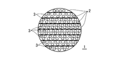
- FIG. FIG. 4 is a diagram schematically showing a cross section of the fixture rod according to one embodiment of the present invention, taken along a plane perpendicular to its central axis.
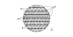
- FIG. 4 is a diagram schematically showing a cross section of the fixture rod according to one embodiment of the present invention, taken along a plane perpendicular to its central axis.
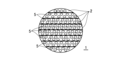
- FIG. 4 is a diagram schematically showing a cross section of the fixture rod according to one embodiment of the present invention, taken along a plane perpendicular to its central axis.
- FIG. 4 is a diagram schematically showing a cross section of the fixture rod according to one embodiment of the present invention, taken along a plane perpendicular to its central axis.
- FIG. 1 is a diagram showing a spinal fixation device 10 including a fixation device rod 1 according to one embodiment of the present invention.
- the spinal fixator 10 includes a plurality of screw members 18 (two screw members 18 in the illustrated example) that are fixed to the bones of the vertebrae, and a fixator rod attached to the screw members 18 .
- a plurality of rod fixing members 20 (two rod fixing members 20 in the illustrated example) having receiving recesses 21 and pressing members 22, and inserted into the recesses 21 of the plurality of rod fixing members 20 and secured by the pressing members 22. and a fixture rod 1 .
- a fastener rod 1 according to an embodiment of the present invention includes a reinforcing fiber layer 2, a resin layer 3 (example shown in FIG. 2), and a reinforcing fiber layer 4 (different from the fibers of the reinforcing fiber layer) when viewed in cross section.
- the example shown in FIG. 3) or the reinforcing fiber layer 5 (example shown in FIG. 4) having fibers oblique to the fiber direction of the reinforcing fiber layer (example shown in FIG. 4) are alternately formed in multiple layers.
- Any one of the reinforcing fiber layers 5 (example shown in FIG. 4) having fibers oriented obliquely is formed to have a thickness of 0.01 mm to 0.25 mm, and the thickness of the layer is may vary depending on the location of the layer (ie, the thickness of the layer may be formed so that there are thin portions and thick portions).
- the layer may be intermittently formed (i.e., the layer has thin portions and thick portions, as well as intervening portions where the layer has a thickness of 0). may be used).
- the fastener rod 1 according to one embodiment of the present invention is broken, the resin layer sandwiched between the reinforcing fiber layers, the reinforcing fiber layer different from the fibers of the reinforcing fiber layer, or the fiber direction of the reinforcing fiber layer
- the reinforcing fiber layer will be reduced from becoming spiky when the rod breaks, resulting in safety for the human body. It has been found that it is possible to significantly improve the
- the reinforcing fiber layer 2 is a fiber-reinforced resin, and carbon, glass, boron, SiC or aramid is used as the fiber, and epoxy, phenol, non-aluminum resin is used as the resin.
- Saturated polyesters, PA, PC, PPSU, POM, PP, PE, ABS, PS, PAEK or PEEK are used. In this way, it is possible to increase the bending rigidity and strength of the fixture rod 1 .
- the resin of the resin layer 3 is epoxy, phenol, unsaturated polyester, PA, PC, PPSU, POM, PP, PE, ABS, PS, PAEK or PEEK. is.
- the reinforcing fiber layer 4 different from the fibers of the reinforcing fiber layer 2 is a fiber-reinforced resin, and the fibers are carbon, glass, boron, SiC, or aramid. , epoxy, phenol, unsaturated polyester, PA, PC, PPSU, POM, PP, PE, ABS, PS, PAEK or PEEK as resin.
- the reason for using a reinforcing fiber layer different from the fibers of the reinforcing fiber layer is that by using different materials, it is possible to impart different properties such as flexibility and vibration absorption in addition to rigidity and strength. .
- the reinforcing fiber layer or the reinforcing fiber layer different from the fibers of the reinforcing fiber layer is formed in a woven fabric in which the fibers are aligned in one direction. may be oriented or randomly oriented.
- the fiber direction of the reinforcing fiber layer 5 having fibers oblique to the fiber direction of the reinforcing fiber layer 2 is in the range of 10° to 90°. You may make it obliquely by . By arranging an appropriate lamination structure in this way, it is possible to achieve the target strength and rigidity.
- each layer is the same layer or a different layer (the same applies hereinafter).
- the resin layer 3 may be two layers (in this case, each layer is the same), and the resin layer 3 and the reinforcing fiber layer 4 are different from the fibers of the reinforcing fiber layer.
- Two layers may be provided.
- a desired combination may be selected from the above layers and provided. In this way, the target strength and rigidity can be achieved by arranging an appropriate lamination structure.
- the fibers of the reinforcing fiber layer 3 are configured to be long fibers. In this way, since the fibers of the reinforcing fiber layer 3 are long fibers, it is possible to further increase the bending rigidity and increase the strength.
- the fiber content rate of the reinforcing fiber layer 3 is configured to be 60% by weight or more. In this way, the fiber layer in which the long fibers are concentrated at a high density makes it possible to form the fixture rod 1 with high rigidity and excellent durability.
- the fiber direction of the reinforcing fiber layer is aligned, and the thickness of the layer is, for example, in the range of 0.02 mm to 0.25 mm. In this way, the density of the resin is made uniform, and it is possible to reduce variations in strength depending on the part.
- step 1 a reinforcing fiber layer 2, a resin layer 3, a reinforcing fiber layer 4 different from the fibers of the reinforcing fiber layer, or a reinforcing fiber layer 5 having fibers oblique to the fiber direction of the reinforcing fiber layer.
- Any layer is cut to a predetermined size (layer cutting step).
- step 2 each layer is stacked in a predetermined arrangement (layer stacking process).
- step 3 it is set in a predetermined mold and molded under predetermined conditions (for example, a temperature of 140° C. and a pressure of 0.1 to 0.5 Mpa) (molding step).
- step 4 the final shape and dimensions are processed (processing step).
- a fixture rod 1 according to an embodiment of the present invention is formed.
- fastener rod 1 formed in this manner, damage during screw fixation is reduced, high rigidity and durability due to deformation load are high, and safety is ensured even when broken. It is possible to provide a rod for fasteners with significantly improved performance.
- the resin layer sandwiched between the reinforcing fiber layers, the reinforcing fiber layer different from the fibers of the reinforcing fiber layer, or the fiber direction of the reinforcing fiber layer By concentrating the stress on any one of the reinforcing fiber layers having fibers obliquely oriented with respect to the rod, the reinforcing fiber layer will be reduced from becoming spiky when the rod breaks, resulting in safety for the human body. It has been found that it is possible to significantly improve the
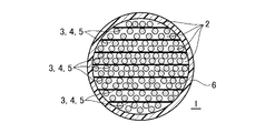
- FIG. 5 is a view of the fixing tool rod 1 shown in FIG. 1 in the XX cross section shown in the figure.
- a rod 1 for a fastener according to one embodiment of the present invention includes a reinforcing fiber layer 2, a resin layer 3, a reinforcing fiber layer 4 different from the fibers of the reinforcing fiber layer, or a fiber direction of the reinforcing fiber layer when viewed in cross section.
- a plurality of layers of reinforcing fiber layers 5 having fibers obliquely oriented with respect to each other are alternately formed, and a coating layer 6 is further formed on the outer surface of the rod 1 for fixture.
- the coating layer 6 may be, for example, the same as the resin of the layer used for the rod 1 for fixtures described above, but is not limited thereto. In this way, it is possible to further reduce the reinforcing fiber layer from becoming thorn-like when the rod breaks, and as a result, it is possible to further enhance the safety to the human body.
- each component described herein is not limited to those explicitly described in the embodiments, and each component may be included within the scope of the present invention. can be modified to have dimensions, materials, and arrangements of Also, components not explicitly described in this specification may be added to the described embodiments, and some of the components described in each embodiment may be omitted.
- Fixture rod 2 Reinforcing fiber layer 3
- Resin layer 4 Reinforcing fiber layer different from the fibers of the reinforcing fiber layer 5
- Covering layer 10 Spinal fixation tool 18 screw member 20 rod fixing member 21 recess 22 pressing member
Landscapes
- Health & Medical Sciences (AREA)
- Orthopedic Medicine & Surgery (AREA)
- Life Sciences & Earth Sciences (AREA)
- Surgery (AREA)
- Neurology (AREA)
- Animal Behavior & Ethology (AREA)
- Veterinary Medicine (AREA)
- Public Health (AREA)
- Heart & Thoracic Surgery (AREA)
- General Health & Medical Sciences (AREA)
- Engineering & Computer Science (AREA)
- Biomedical Technology (AREA)
- Vascular Medicine (AREA)
- Molecular Biology (AREA)
- Medical Informatics (AREA)
- Nuclear Medicine, Radiotherapy & Molecular Imaging (AREA)
- Epidemiology (AREA)
- Chemical & Material Sciences (AREA)
- Composite Materials (AREA)
- Materials Engineering (AREA)
- Cardiology (AREA)
- Oral & Maxillofacial Surgery (AREA)
- Transplantation (AREA)
- Surgical Instruments (AREA)
- Prostheses (AREA)
- Materials For Medical Uses (AREA)
Abstract
Description
本出願は、日本国特許出願2021-129232(2021年8月5日出願)に基づく優先権を主張し、その内容は参照により全体として本明細書に組み込まれる。
本発明は、脊椎を固定するための固定具に用いる固定具用ロッドに関する。
2 強化繊維層
3 樹脂層
4 強化繊維層の繊維とは異なる強化繊維層
5 強化繊維層の繊維方向に対して斜向する繊維を有する強化繊維層
6 被覆層
10 脊椎用固定具
18 スクリュー部材
20 ロッド固定部材
21 凹部
22 押圧部材
Claims (10)
- 固定具用ロッドであって、
断面でみて、強化繊維層と、樹脂層、該強化繊維層の繊維とは異なる強化繊維層又は該強化繊維層の繊維方向に対して斜向する繊維を有する強化繊維層のいずれかの層と、が交互にそれぞれ複数層形成されていることを特徴とする、固定具用ロッド。 - 前記強化繊維層は、繊維強化樹脂であり、繊維として、カーボン、ガラス、ボロン、SiC又はアラミドを用い、樹脂としてエポキシ、フェノール、不飽和ポリエステル、PA、PC、PPSU、POM、PP、PE、ABS、PS、PAEK又はPEEKを用いる、請求項1に記載の固定具用ロッド。
- 前記樹脂層の樹脂は、エポキシ、フェノール、不飽和ポリエステル、PA、PC、PPSU、POM、PP、PE、ABS、PS、PAEK又はPEEKである、請求項1又は2に記載の固定具用ロッド。
- 前記強化繊維層の繊維とは異なる強化繊維層は、繊維強化樹脂であり、繊維として、カーボン、ガラス、ボロン、SiC又はアラミドを用い、樹脂としてエポキシ、フェノール、不飽和ポリエステル、PA、PC、PPSU、POM、PP、PE、ABS、PS、PAEK又はPEEKを用いる、請求項1から3までのいずれか1項に記載の固定具用ロッド。
- 前記強化繊維層又は前記強化繊維層の繊維とは異なる強化繊維層は、繊維が一方向に引き揃えられている、織物状に形成されている又はランダムに配向されている、請求項1から4までのいずれか1項に記載の固定具用ロッド。
- 前記強化繊維層の繊維方向に対して斜向する繊維を有する強化繊維層の繊維方向は、10°から90°の範囲で斜向する、請求項1から4までのいずれか1項に記載の固定具用ロッド。
- 樹脂層、該強化繊維層の繊維とは異なる強化繊維層又は該強化繊維層の繊維方向に対して斜向する繊維を有する強化繊維層のいずれかの層が複数層設けられる場合、各層は同じ層又は異なる層である、請求項1から6までのいずれか1項に記載の固定具用ロッド。
- 前記強化繊維層の繊維は長繊維である、請求項1から7までのいずれか1項に記載の固定具用ロッド。
- 前記強化繊維層の繊維含有率は、60重量%以上である、請求項1から8までのいずれか1項に記載の固定具用ロッド。
- 前記強化繊維層の繊維方向は引き揃えられており、該層の厚みは、0.02mmから0.25mmの範囲にある、請求項1から9までのいずれか1項に記載の固定具用ロッド。
Priority Applications (4)
| Application Number | Priority Date | Filing Date | Title |
|---|---|---|---|
| US18/566,193 US20240252211A1 (en) | 2021-08-05 | 2022-03-03 | Rod for spinal brace |
| CN202280038416.5A CN117396159A (zh) | 2021-08-05 | 2022-03-03 | 脊椎固定件用杆 |
| EP22852556.4A EP4382143B1 (en) | 2021-08-05 | 2022-03-03 | Rod for spinal brace |
| KR1020247006830A KR20240036692A (ko) | 2021-08-05 | 2022-03-03 | 척추 고정구용 로드 |
Applications Claiming Priority (2)
| Application Number | Priority Date | Filing Date | Title |
|---|---|---|---|
| JP2021-129232 | 2021-08-05 | ||
| JP2021129232A JP7626681B2 (ja) | 2021-08-05 | 2021-08-05 | 脊椎固定具用ロッド |
Publications (1)
| Publication Number | Publication Date |
|---|---|
| WO2023013127A1 true WO2023013127A1 (ja) | 2023-02-09 |
Family
ID=85155493
Family Applications (1)
| Application Number | Title | Priority Date | Filing Date |
|---|---|---|---|
| PCT/JP2022/009087 Ceased WO2023013127A1 (ja) | 2021-08-05 | 2022-03-03 | 脊椎固定具用ロッド |
Country Status (6)
| Country | Link |
|---|---|
| US (1) | US20240252211A1 (ja) |
| EP (1) | EP4382143B1 (ja) |
| JP (2) | JP7626681B2 (ja) |
| KR (1) | KR20240036692A (ja) |
| CN (1) | CN117396159A (ja) |
| WO (1) | WO2023013127A1 (ja) |
Cited By (2)
| Publication number | Priority date | Publication date | Assignee | Title |
|---|---|---|---|---|
| WO2024202208A1 (ja) * | 2023-03-29 | 2024-10-03 | グローブライド株式会社 | 脊椎内固定器具用ロッド |
| WO2024204311A1 (ja) * | 2023-03-31 | 2024-10-03 | グローブライド株式会社 | 破断断片が離散し難い脊椎内固定器具用ロッド |
Families Citing this family (1)
| Publication number | Priority date | Publication date | Assignee | Title |
|---|---|---|---|---|
| JP7626681B2 (ja) * | 2021-08-05 | 2025-02-04 | グローブライド株式会社 | 脊椎固定具用ロッド |
Citations (5)
| Publication number | Priority date | Publication date | Assignee | Title |
|---|---|---|---|---|
| JP2007530216A (ja) * | 2004-03-30 | 2007-11-01 | デピュイ・スパイン・エスエイアールエル | ダブルリードの骨ねじ |
| JP2009524496A (ja) * | 2006-01-26 | 2009-07-02 | ウォーソー・オーソペディック・インコーポレーテッド | 延長レシーバを有する脊柱アンカー組立体 |
| JP2011508623A (ja) | 2007-12-19 | 2011-03-17 | デピュイ・スパイン・インコーポレイテッド | ポリマー椎弓根ロッド及び製造方法 |
| JP2017538483A (ja) * | 2014-12-26 | 2017-12-28 | オッシオ リミテッド | 連続繊維で補強されたバイオコンポジットの医療用インプラント |
| JP2021129232A (ja) | 2020-02-14 | 2021-09-02 | ザ・ボーイング・カンパニーThe Boeing Company | 閉ループフィードバックを使用する適応型自己最適化ネットワーク |
Family Cites Families (9)
| Publication number | Priority date | Publication date | Assignee | Title |
|---|---|---|---|---|
| JPH06322999A (ja) * | 1993-05-14 | 1994-11-22 | Tonen Corp | コンクリート柱 |
| US5556687A (en) * | 1994-10-14 | 1996-09-17 | Acromed Corporation | Composite structure suitable for use as a bone plate and method for making said structure |
| JP4784362B2 (ja) * | 2005-03-25 | 2011-10-05 | 東レ株式会社 | 管状体 |
| US20070233073A1 (en) * | 2006-03-02 | 2007-10-04 | Sdgi Holdings, Inc. | Spinal rod characterized by a time-varying stiffness |
| DE602006004168D1 (de) * | 2006-03-31 | 2009-01-22 | Stryker Trauma Sa | Externes Fixierelement mit einer rauhen, abgetragenen Oberfläche |
| EP1972289B1 (en) * | 2007-03-23 | 2018-10-17 | coLigne AG | Elongated stabilization member and bone anchor useful in bone and especially spinal repair processes |
| CN101536927A (zh) * | 2008-03-20 | 2009-09-23 | 冠亚国际科技股份有限公司 | 脊椎钉间的多功能挠性连杆 |
| JP2013540468A (ja) * | 2010-09-08 | 2013-11-07 | ロジャー・ピー・ジャクソン | 弾性部および非弾性部を有する動的固定化部材 |
| JP7626681B2 (ja) * | 2021-08-05 | 2025-02-04 | グローブライド株式会社 | 脊椎固定具用ロッド |
-
2021
- 2021-08-05 JP JP2021129232A patent/JP7626681B2/ja active Active
-
2022
- 2022-03-03 WO PCT/JP2022/009087 patent/WO2023013127A1/ja not_active Ceased
- 2022-03-03 KR KR1020247006830A patent/KR20240036692A/ko active Pending
- 2022-03-03 CN CN202280038416.5A patent/CN117396159A/zh active Pending
- 2022-03-03 US US18/566,193 patent/US20240252211A1/en active Pending
- 2022-03-03 EP EP22852556.4A patent/EP4382143B1/en active Active
-
2025
- 2025-01-23 JP JP2025009601A patent/JP7829751B2/ja active Active
Patent Citations (5)
| Publication number | Priority date | Publication date | Assignee | Title |
|---|---|---|---|---|
| JP2007530216A (ja) * | 2004-03-30 | 2007-11-01 | デピュイ・スパイン・エスエイアールエル | ダブルリードの骨ねじ |
| JP2009524496A (ja) * | 2006-01-26 | 2009-07-02 | ウォーソー・オーソペディック・インコーポレーテッド | 延長レシーバを有する脊柱アンカー組立体 |
| JP2011508623A (ja) | 2007-12-19 | 2011-03-17 | デピュイ・スパイン・インコーポレイテッド | ポリマー椎弓根ロッド及び製造方法 |
| JP2017538483A (ja) * | 2014-12-26 | 2017-12-28 | オッシオ リミテッド | 連続繊維で補強されたバイオコンポジットの医療用インプラント |
| JP2021129232A (ja) | 2020-02-14 | 2021-09-02 | ザ・ボーイング・カンパニーThe Boeing Company | 閉ループフィードバックを使用する適応型自己最適化ネットワーク |
Non-Patent Citations (1)
| Title |
|---|
| See also references of EP4382143A4 |
Cited By (3)
| Publication number | Priority date | Publication date | Assignee | Title |
|---|---|---|---|---|
| WO2024202208A1 (ja) * | 2023-03-29 | 2024-10-03 | グローブライド株式会社 | 脊椎内固定器具用ロッド |
| WO2024204311A1 (ja) * | 2023-03-31 | 2024-10-03 | グローブライド株式会社 | 破断断片が離散し難い脊椎内固定器具用ロッド |
| JP2024145952A (ja) * | 2023-03-31 | 2024-10-15 | グローブライド株式会社 | 破断断片が離散し難い脊椎内固定器具用ロッド |
Also Published As
| Publication number | Publication date |
|---|---|
| JP2025063281A (ja) | 2025-04-15 |
| US20240252211A1 (en) | 2024-08-01 |
| CN117396159A (zh) | 2024-01-12 |
| EP4382143A1 (en) | 2024-06-12 |
| JP2023023584A (ja) | 2023-02-16 |
| KR20240036692A (ko) | 2024-03-20 |
| EP4382143B1 (en) | 2026-01-28 |
| EP4382143A4 (en) | 2024-12-18 |
| JP7829751B2 (ja) | 2026-03-13 |
| JP7626681B2 (ja) | 2025-02-04 |
Similar Documents
| Publication | Publication Date | Title |
|---|---|---|
| JP7829751B2 (ja) | 脊椎固定具用ロッド | |
| CN103415722B (zh) | 纤维增强塑料制弹簧 | |
| JP3040335B2 (ja) | 複合構造体及びその製造方法 | |
| EP2737995A1 (en) | Fiber-reinforced composite material | |
| JP2010537889A (ja) | 複合材料から形成される構造フレーム及び該構造フレームを備えている航空機の胴体 | |
| JP7446965B2 (ja) | 脊椎固定具用ロッド | |
| KR960000558B1 (ko) | 일방향 프리프렉 및 탄소섬유 강화 복합재료 | |
| JP7432538B2 (ja) | 脊椎固定具用ロッド及びこれを備える脊椎用固定具 | |
| KR20210024821A (ko) | 등방성 복합재료 | |
| JP2024142240A (ja) | 脊椎内固定器具用ロッド | |
| WO2022158058A1 (ja) | 脊椎固定具用ロッド及びこれを備える脊椎用固定具 | |
| WO2024204311A1 (ja) | 破断断片が離散し難い脊椎内固定器具用ロッド | |
| JP2009155760A (ja) | 繊維強化複合材料用織物 | |
| Tanabi et al. | Stress concentrations in composites with microvascular channels |
Legal Events
| Date | Code | Title | Description |
|---|---|---|---|
| 121 | Ep: the epo has been informed by wipo that ep was designated in this application |
Ref document number: 22852556 Country of ref document: EP Kind code of ref document: A1 |
|
| WWE | Wipo information: entry into national phase |
Ref document number: 202280038416.5 Country of ref document: CN |
|
| WWE | Wipo information: entry into national phase |
Ref document number: 18566193 Country of ref document: US |
|
| ENP | Entry into the national phase |
Ref document number: 20247006830 Country of ref document: KR Kind code of ref document: A |
|
| NENP | Non-entry into the national phase |
Ref country code: DE |
|
| ENP | Entry into the national phase |
Ref document number: 2022852556 Country of ref document: EP Effective date: 20240305 |
|
| WWG | Wipo information: grant in national office |
Ref document number: 2022852556 Country of ref document: EP |