WO2023013357A1 - 電力変換装置 - Google Patents
電力変換装置 Download PDFInfo
- Publication number
- WO2023013357A1 WO2023013357A1 PCT/JP2022/026922 JP2022026922W WO2023013357A1 WO 2023013357 A1 WO2023013357 A1 WO 2023013357A1 JP 2022026922 W JP2022026922 W JP 2022026922W WO 2023013357 A1 WO2023013357 A1 WO 2023013357A1
- Authority
- WO
- WIPO (PCT)
- Prior art keywords
- power storage
- storage unit
- supply source
- potential side
- switch
- Prior art date
- Legal status (The legal status is an assumption and is not a legal conclusion. Google has not performed a legal analysis and makes no representation as to the accuracy of the status listed.)
- Ceased
Links
Images





















Classifications
-
- B—PERFORMING OPERATIONS; TRANSPORTING
- B60—VEHICLES IN GENERAL
- B60L—PROPULSION OF ELECTRICALLY-PROPELLED VEHICLES; SUPPLYING ELECTRIC POWER FOR AUXILIARY EQUIPMENT OF ELECTRICALLY-PROPELLED VEHICLES; ELECTRODYNAMIC BRAKE SYSTEMS FOR VEHICLES IN GENERAL; MAGNETIC SUSPENSION OR LEVITATION FOR VEHICLES; MONITORING OPERATING VARIABLES OF ELECTRICALLY-PROPELLED VEHICLES; ELECTRIC SAFETY DEVICES FOR ELECTRICALLY-PROPELLED VEHICLES
- B60L50/00—Electric propulsion with power supplied within the vehicle
- B60L50/50—Electric propulsion with power supplied within the vehicle using propulsion power supplied by batteries or fuel cells
- B60L50/60—Electric propulsion with power supplied within the vehicle using propulsion power supplied by batteries or fuel cells using power supplied by batteries
- B60L50/66—Arrangements of batteries
-
- B—PERFORMING OPERATIONS; TRANSPORTING
- B60—VEHICLES IN GENERAL
- B60L—PROPULSION OF ELECTRICALLY-PROPELLED VEHICLES; SUPPLYING ELECTRIC POWER FOR AUXILIARY EQUIPMENT OF ELECTRICALLY-PROPELLED VEHICLES; ELECTRODYNAMIC BRAKE SYSTEMS FOR VEHICLES IN GENERAL; MAGNETIC SUSPENSION OR LEVITATION FOR VEHICLES; MONITORING OPERATING VARIABLES OF ELECTRICALLY-PROPELLED VEHICLES; ELECTRIC SAFETY DEVICES FOR ELECTRICALLY-PROPELLED VEHICLES
- B60L50/00—Electric propulsion with power supplied within the vehicle
- B60L50/50—Electric propulsion with power supplied within the vehicle using propulsion power supplied by batteries or fuel cells
- B60L50/51—Electric propulsion with power supplied within the vehicle using propulsion power supplied by batteries or fuel cells characterised by AC-motors
-
- B—PERFORMING OPERATIONS; TRANSPORTING
- B60—VEHICLES IN GENERAL
- B60L—PROPULSION OF ELECTRICALLY-PROPELLED VEHICLES; SUPPLYING ELECTRIC POWER FOR AUXILIARY EQUIPMENT OF ELECTRICALLY-PROPELLED VEHICLES; ELECTRODYNAMIC BRAKE SYSTEMS FOR VEHICLES IN GENERAL; MAGNETIC SUSPENSION OR LEVITATION FOR VEHICLES; MONITORING OPERATING VARIABLES OF ELECTRICALLY-PROPELLED VEHICLES; ELECTRIC SAFETY DEVICES FOR ELECTRICALLY-PROPELLED VEHICLES
- B60L15/00—Methods, circuits, or devices for controlling the traction-motor speed of electrically-propelled vehicles
- B60L15/007—Physical arrangements or structures of drive train converters specially adapted for the propulsion motors of electric vehicles
-
- B—PERFORMING OPERATIONS; TRANSPORTING
- B60—VEHICLES IN GENERAL
- B60L—PROPULSION OF ELECTRICALLY-PROPELLED VEHICLES; SUPPLYING ELECTRIC POWER FOR AUXILIARY EQUIPMENT OF ELECTRICALLY-PROPELLED VEHICLES; ELECTRODYNAMIC BRAKE SYSTEMS FOR VEHICLES IN GENERAL; MAGNETIC SUSPENSION OR LEVITATION FOR VEHICLES; MONITORING OPERATING VARIABLES OF ELECTRICALLY-PROPELLED VEHICLES; ELECTRIC SAFETY DEVICES FOR ELECTRICALLY-PROPELLED VEHICLES
- B60L58/00—Methods or circuit arrangements for monitoring or controlling batteries or fuel cells, specially adapted for electric vehicles
- B60L58/10—Methods or circuit arrangements for monitoring or controlling batteries or fuel cells, specially adapted for electric vehicles for monitoring or controlling batteries
- B60L58/18—Methods or circuit arrangements for monitoring or controlling batteries or fuel cells, specially adapted for electric vehicles for monitoring or controlling batteries of two or more battery modules
- B60L58/19—Switching between serial connection and parallel connection of battery modules
-
- B—PERFORMING OPERATIONS; TRANSPORTING
- B60—VEHICLES IN GENERAL
- B60L—PROPULSION OF ELECTRICALLY-PROPELLED VEHICLES; SUPPLYING ELECTRIC POWER FOR AUXILIARY EQUIPMENT OF ELECTRICALLY-PROPELLED VEHICLES; ELECTRODYNAMIC BRAKE SYSTEMS FOR VEHICLES IN GENERAL; MAGNETIC SUSPENSION OR LEVITATION FOR VEHICLES; MONITORING OPERATING VARIABLES OF ELECTRICALLY-PROPELLED VEHICLES; ELECTRIC SAFETY DEVICES FOR ELECTRICALLY-PROPELLED VEHICLES
- B60L58/00—Methods or circuit arrangements for monitoring or controlling batteries or fuel cells, specially adapted for electric vehicles
- B60L58/10—Methods or circuit arrangements for monitoring or controlling batteries or fuel cells, specially adapted for electric vehicles for monitoring or controlling batteries
- B60L58/18—Methods or circuit arrangements for monitoring or controlling batteries or fuel cells, specially adapted for electric vehicles for monitoring or controlling batteries of two or more battery modules
- B60L58/22—Balancing the charge of battery modules
-
- H—ELECTRICITY
- H02—GENERATION; CONVERSION OR DISTRIBUTION OF ELECTRIC POWER
- H02J—ELECTRIC POWER NETWORKS; CIRCUIT ARRANGEMENTS OR SYSTEMS FOR SUPPLYING OR DISTRIBUTING ELECTRIC POWER; SYSTEMS FOR STORING ELECTRIC ENERGY
- H02J7/00—Circuit arrangements for charging or discharging batteries or for supplying loads from batteries
- H02J7/02—Circuit arrangements for charging or discharging batteries or for supplying loads from batteries for charging batteries from AC mains by converters
-
- H—ELECTRICITY
- H02—GENERATION; CONVERSION OR DISTRIBUTION OF ELECTRIC POWER
- H02J—ELECTRIC POWER NETWORKS; CIRCUIT ARRANGEMENTS OR SYSTEMS FOR SUPPLYING OR DISTRIBUTING ELECTRIC POWER; SYSTEMS FOR STORING ELECTRIC ENERGY
- H02J7/00—Circuit arrangements for charging or discharging batteries or for supplying loads from batteries
- H02J7/50—Circuit arrangements for charging or discharging batteries or for supplying loads from batteries acting upon multiple batteries simultaneously or sequentially
-
- H—ELECTRICITY
- H02—GENERATION; CONVERSION OR DISTRIBUTION OF ELECTRIC POWER
- H02J—ELECTRIC POWER NETWORKS; CIRCUIT ARRANGEMENTS OR SYSTEMS FOR SUPPLYING OR DISTRIBUTING ELECTRIC POWER; SYSTEMS FOR STORING ELECTRIC ENERGY
- H02J7/00—Circuit arrangements for charging or discharging batteries or for supplying loads from batteries
- H02J7/50—Circuit arrangements for charging or discharging batteries or for supplying loads from batteries acting upon multiple batteries simultaneously or sequentially
- H02J7/52—Circuit arrangements for charging or discharging batteries or for supplying loads from batteries acting upon multiple batteries simultaneously or sequentially for charge balancing, e.g. equalisation of charge between batteries
- H02J7/54—Passive balancing, e.g. using resistors or parallel MOSFETs
-
- H—ELECTRICITY
- H02—GENERATION; CONVERSION OR DISTRIBUTION OF ELECTRIC POWER
- H02M—APPARATUS FOR CONVERSION BETWEEN AC AND AC, BETWEEN AC AND DC, OR BETWEEN DC AND DC, AND FOR USE WITH MAINS OR SIMILAR POWER SUPPLY SYSTEMS; CONVERSION OF DC OR AC INPUT POWER INTO SURGE OUTPUT POWER; CONTROL OR REGULATION THEREOF
- H02M1/00—Details of apparatus for conversion
- H02M1/0095—Hybrid converter topologies, e.g. NPC mixed with flying capacitor, thyristor converter mixed with MMC or charge pump mixed with buck
-
- H—ELECTRICITY
- H02—GENERATION; CONVERSION OR DISTRIBUTION OF ELECTRIC POWER
- H02M—APPARATUS FOR CONVERSION BETWEEN AC AND AC, BETWEEN AC AND DC, OR BETWEEN DC AND DC, AND FOR USE WITH MAINS OR SIMILAR POWER SUPPLY SYSTEMS; CONVERSION OF DC OR AC INPUT POWER INTO SURGE OUTPUT POWER; CONTROL OR REGULATION THEREOF
- H02M1/00—Details of apparatus for conversion
- H02M1/08—Circuits specially adapted for the generation of control voltages for semiconductor devices incorporated in static converters
- H02M1/088—Circuits specially adapted for the generation of control voltages for semiconductor devices incorporated in static converters for the simultaneous control of series or parallel connected semiconductor devices
-
- H—ELECTRICITY
- H02—GENERATION; CONVERSION OR DISTRIBUTION OF ELECTRIC POWER
- H02M—APPARATUS FOR CONVERSION BETWEEN AC AND AC, BETWEEN AC AND DC, OR BETWEEN DC AND DC, AND FOR USE WITH MAINS OR SIMILAR POWER SUPPLY SYSTEMS; CONVERSION OF DC OR AC INPUT POWER INTO SURGE OUTPUT POWER; CONTROL OR REGULATION THEREOF
- H02M3/00—Conversion of DC power input into DC power output
- H02M3/02—Conversion of DC power input into DC power output without intermediate conversion into AC
- H02M3/04—Conversion of DC power input into DC power output without intermediate conversion into AC by static converters
- H02M3/10—Conversion of DC power input into DC power output without intermediate conversion into AC by static converters using discharge tubes with control electrode or semiconductor devices with control electrode
- H02M3/145—Conversion of DC power input into DC power output without intermediate conversion into AC by static converters using discharge tubes with control electrode or semiconductor devices with control electrode using devices of a triode or transistor type requiring continuous application of a control signal
- H02M3/155—Conversion of DC power input into DC power output without intermediate conversion into AC by static converters using discharge tubes with control electrode or semiconductor devices with control electrode using devices of a triode or transistor type requiring continuous application of a control signal using semiconductor devices only
- H02M3/156—Conversion of DC power input into DC power output without intermediate conversion into AC by static converters using discharge tubes with control electrode or semiconductor devices with control electrode using devices of a triode or transistor type requiring continuous application of a control signal using semiconductor devices only with automatic control of output voltage or current, e.g. switching regulators
- H02M3/158—Conversion of DC power input into DC power output without intermediate conversion into AC by static converters using discharge tubes with control electrode or semiconductor devices with control electrode using devices of a triode or transistor type requiring continuous application of a control signal using semiconductor devices only with automatic control of output voltage or current, e.g. switching regulators including plural semiconductor devices as final control devices for a single load
- H02M3/1584—Conversion of DC power input into DC power output without intermediate conversion into AC by static converters using discharge tubes with control electrode or semiconductor devices with control electrode using devices of a triode or transistor type requiring continuous application of a control signal using semiconductor devices only with automatic control of output voltage or current, e.g. switching regulators including plural semiconductor devices as final control devices for a single load with a plurality of power processing stages connected in parallel
-
- H—ELECTRICITY
- H02—GENERATION; CONVERSION OR DISTRIBUTION OF ELECTRIC POWER
- H02M—APPARATUS FOR CONVERSION BETWEEN AC AND AC, BETWEEN AC AND DC, OR BETWEEN DC AND DC, AND FOR USE WITH MAINS OR SIMILAR POWER SUPPLY SYSTEMS; CONVERSION OF DC OR AC INPUT POWER INTO SURGE OUTPUT POWER; CONTROL OR REGULATION THEREOF
- H02M7/00—Conversion of AC power input into DC power output; Conversion of DC power input into AC power output
- H02M7/42—Conversion of DC power input into AC power output without possibility of reversal
- H02M7/44—Conversion of DC power input into AC power output without possibility of reversal by static converters
- H02M7/48—Conversion of DC power input into AC power output without possibility of reversal by static converters using discharge tubes with control electrode or semiconductor devices with control electrode
- H02M7/53—Conversion of DC power input into AC power output without possibility of reversal by static converters using discharge tubes with control electrode or semiconductor devices with control electrode using devices of a triode or transistor type requiring continuous application of a control signal
- H02M7/537—Conversion of DC power input into AC power output without possibility of reversal by static converters using discharge tubes with control electrode or semiconductor devices with control electrode using devices of a triode or transistor type requiring continuous application of a control signal using semiconductor devices only, e.g. single switched pulse inverters
- H02M7/5387—Conversion of DC power input into AC power output without possibility of reversal by static converters using discharge tubes with control electrode or semiconductor devices with control electrode using devices of a triode or transistor type requiring continuous application of a control signal using semiconductor devices only, e.g. single switched pulse inverters in a bridge configuration
- H02M7/53871—Conversion of DC power input into AC power output without possibility of reversal by static converters using discharge tubes with control electrode or semiconductor devices with control electrode using devices of a triode or transistor type requiring continuous application of a control signal using semiconductor devices only, e.g. single switched pulse inverters in a bridge configuration with automatic control of output voltage or current
-
- H—ELECTRICITY
- H02—GENERATION; CONVERSION OR DISTRIBUTION OF ELECTRIC POWER
- H02M—APPARATUS FOR CONVERSION BETWEEN AC AND AC, BETWEEN AC AND DC, OR BETWEEN DC AND DC, AND FOR USE WITH MAINS OR SIMILAR POWER SUPPLY SYSTEMS; CONVERSION OF DC OR AC INPUT POWER INTO SURGE OUTPUT POWER; CONTROL OR REGULATION THEREOF
- H02M7/00—Conversion of AC power input into DC power output; Conversion of DC power input into AC power output
- H02M7/42—Conversion of DC power input into AC power output without possibility of reversal
- H02M7/44—Conversion of DC power input into AC power output without possibility of reversal by static converters
- H02M7/48—Conversion of DC power input into AC power output without possibility of reversal by static converters using discharge tubes with control electrode or semiconductor devices with control electrode
- H02M7/53—Conversion of DC power input into AC power output without possibility of reversal by static converters using discharge tubes with control electrode or semiconductor devices with control electrode using devices of a triode or transistor type requiring continuous application of a control signal
- H02M7/537—Conversion of DC power input into AC power output without possibility of reversal by static converters using discharge tubes with control electrode or semiconductor devices with control electrode using devices of a triode or transistor type requiring continuous application of a control signal using semiconductor devices only, e.g. single switched pulse inverters
- H02M7/5387—Conversion of DC power input into AC power output without possibility of reversal by static converters using discharge tubes with control electrode or semiconductor devices with control electrode using devices of a triode or transistor type requiring continuous application of a control signal using semiconductor devices only, e.g. single switched pulse inverters in a bridge configuration
- H02M7/53871—Conversion of DC power input into AC power output without possibility of reversal by static converters using discharge tubes with control electrode or semiconductor devices with control electrode using devices of a triode or transistor type requiring continuous application of a control signal using semiconductor devices only, e.g. single switched pulse inverters in a bridge configuration with automatic control of output voltage or current
- H02M7/53873—Conversion of DC power input into AC power output without possibility of reversal by static converters using discharge tubes with control electrode or semiconductor devices with control electrode using devices of a triode or transistor type requiring continuous application of a control signal using semiconductor devices only, e.g. single switched pulse inverters in a bridge configuration with automatic control of output voltage or current with digital control
-
- B—PERFORMING OPERATIONS; TRANSPORTING
- B60—VEHICLES IN GENERAL
- B60L—PROPULSION OF ELECTRICALLY-PROPELLED VEHICLES; SUPPLYING ELECTRIC POWER FOR AUXILIARY EQUIPMENT OF ELECTRICALLY-PROPELLED VEHICLES; ELECTRODYNAMIC BRAKE SYSTEMS FOR VEHICLES IN GENERAL; MAGNETIC SUSPENSION OR LEVITATION FOR VEHICLES; MONITORING OPERATING VARIABLES OF ELECTRICALLY-PROPELLED VEHICLES; ELECTRIC SAFETY DEVICES FOR ELECTRICALLY-PROPELLED VEHICLES
- B60L2210/00—Converter types
- B60L2210/40—DC to AC converters
-
- B—PERFORMING OPERATIONS; TRANSPORTING
- B60—VEHICLES IN GENERAL
- B60L—PROPULSION OF ELECTRICALLY-PROPELLED VEHICLES; SUPPLYING ELECTRIC POWER FOR AUXILIARY EQUIPMENT OF ELECTRICALLY-PROPELLED VEHICLES; ELECTRODYNAMIC BRAKE SYSTEMS FOR VEHICLES IN GENERAL; MAGNETIC SUSPENSION OR LEVITATION FOR VEHICLES; MONITORING OPERATING VARIABLES OF ELECTRICALLY-PROPELLED VEHICLES; ELECTRIC SAFETY DEVICES FOR ELECTRICALLY-PROPELLED VEHICLES
- B60L2210/00—Converter types
- B60L2210/40—DC to AC converters
- B60L2210/42—Voltage source inverters
-
- B—PERFORMING OPERATIONS; TRANSPORTING
- B60—VEHICLES IN GENERAL
- B60L—PROPULSION OF ELECTRICALLY-PROPELLED VEHICLES; SUPPLYING ELECTRIC POWER FOR AUXILIARY EQUIPMENT OF ELECTRICALLY-PROPELLED VEHICLES; ELECTRODYNAMIC BRAKE SYSTEMS FOR VEHICLES IN GENERAL; MAGNETIC SUSPENSION OR LEVITATION FOR VEHICLES; MONITORING OPERATING VARIABLES OF ELECTRICALLY-PROPELLED VEHICLES; ELECTRIC SAFETY DEVICES FOR ELECTRICALLY-PROPELLED VEHICLES
- B60L2240/00—Control parameters of input or output; Target parameters
- B60L2240/40—Drive Train control parameters
- B60L2240/54—Drive Train control parameters related to batteries
- B60L2240/547—Voltage
-
- H—ELECTRICITY
- H02—GENERATION; CONVERSION OR DISTRIBUTION OF ELECTRIC POWER
- H02J—ELECTRIC POWER NETWORKS; CIRCUIT ARRANGEMENTS OR SYSTEMS FOR SUPPLYING OR DISTRIBUTING ELECTRIC POWER; SYSTEMS FOR STORING ELECTRIC ENERGY
- H02J2105/00—Networks for supplying or distributing electric power characterised by their spatial reach or by the load
- H02J2105/30—Networks for supplying or distributing electric power characterised by their spatial reach or by the load the load networks being external to vehicles, i.e. exchanging power with vehicles
- H02J2105/33—Networks for supplying or distributing electric power characterised by their spatial reach or by the load the load networks being external to vehicles, i.e. exchanging power with vehicles exchanging power with road vehicles
- H02J2105/37—Networks for supplying or distributing electric power characterised by their spatial reach or by the load the load networks being external to vehicles, i.e. exchanging power with vehicles exchanging power with road vehicles exchanging power with electric vehicles [EV] or with hybrid electric vehicles [HEV]
-
- H—ELECTRICITY
- H02—GENERATION; CONVERSION OR DISTRIBUTION OF ELECTRIC POWER
- H02J—ELECTRIC POWER NETWORKS; CIRCUIT ARRANGEMENTS OR SYSTEMS FOR SUPPLYING OR DISTRIBUTING ELECTRIC POWER; SYSTEMS FOR STORING ELECTRIC ENERGY
- H02J2207/00—Details of circuit arrangements for charging or discharging batteries or supplying loads from batteries
- H02J2207/20—Charging or discharging characterised by the power electronics converter
Definitions
- the present disclosure relates to power converters.
- a charge equalization system that includes a series connection of a plurality of unit storage batteries, an insulated DCDC converter, and an auxiliary battery.
- the DCDC converter is individually provided corresponding to each unit storage battery, the output side is connected to the unit storage battery, and the input side is connected to the auxiliary battery. Power is supplied from the auxiliary battery to the unit storage battery by driving the DCDC converter. Thereby, the remaining capacity of each unit storage battery can be equalized.
- Patent Document 1 The system described in Patent Document 1 requires a DCDC converter for each unit storage battery. Therefore, there is a concern that the system will become complicated.
- a main object of the present disclosure is to provide a power conversion device capable of simplifying the configuration.
- the present disclosure provides a power conversion device applied to three or more power storage units connected in series, a rotating electric machine having stator windings; an inverter having upper and lower arm switches and connecting the stator winding and the power storage unit; a high potential side path connected to the high potential side terminal of the upper arm switch; a low potential side path connected to the low potential side terminal of the lower arm switch; a neutral path connected to the neutral of the stator winding; a neutral point switch provided individually corresponding to a battery connection point between a positive electrode terminal and a negative electrode terminal of adjacent power storage units among the power storage units, and connecting the battery connection point and the neutral point path; Prepare.
- the power supply from the supply source power storage unit to the supply destination power storage unit among the power storage units includes the neutral point switch individually provided corresponding to each battery connection point and the neutral point path.
- the stator windings and the inverter are used. Accordingly, it is possible to simplify the configuration for supplying power from the supply source power storage unit to the supply destination power storage unit.
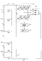
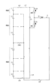
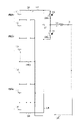
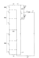
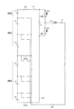
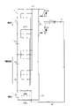
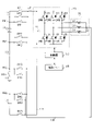
- FIG. 1 is an overall configuration diagram of a power converter according to the first embodiment
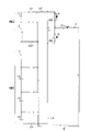
- FIG. 2 is a flowchart showing the procedure of power transfer processing
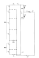
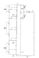
- FIG. 3 is a diagram showing a power feeding mode when the power storage unit of the supply source is at the end on the high potential side
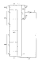
- FIG. 4 is a diagram showing a power feeding mode when the power storage unit of the supply source is at the end on the high potential side
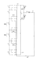
- FIG. 5 is a diagram showing a power feeding mode when the supply source power storage unit is at the end on the low potential side
- FIG. 6 is a diagram showing a power feeding mode when the power storage unit of the supply source is at the end on the low potential side
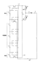
- FIG. 7 is a diagram showing a power supply mode in the case where the supply source power storage unit is sandwiched between the supply destination power storage units
- FIG. 8 is a diagram showing a power supply mode in the case where the supply source power storage unit is sandwiched between the supply destination power storage units
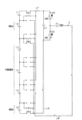
- FIG. 9 is a diagram showing a power supply mode when the supply source power storage unit is sandwiched between the supply destination power storage units
- FIG. 10 is a diagram showing a power supply mode when the supply source power storage unit is sandwiched between the supply destination power storage units
- FIG. 10 is a diagram showing a power supply mode when the supply source power storage unit is sandwiched between the supply destination power storage units
- FIG. 11 is a diagram showing a power supply mode when the supply source power storage unit is sandwiched between the supply destination power storage units;
- FIG. 12 is a diagram showing a power supply mode when the supply source power storage unit is sandwiched between the supply destination power storage units;
- FIG. 13 is a diagram showing a power supply mode when the supply source power storage unit is sandwiched between the supply destination power storage units;
- FIG. 14 is a diagram showing a power supply mode in the case where the supply source power storage unit is sandwiched between the supply destination power storage units;
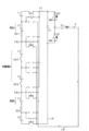
- FIG. 15 is an overall configuration diagram of a power converter according to the second embodiment,
- FIG. 16 is a diagram showing a power supply mode in the case where the supply source power storage unit is sandwiched between the supply destination power storage units;
- FIG. 17 is a diagram showing a power supply mode when the supply source power storage unit is sandwiched between the supply destination power storage units;
- FIG. 18 is a diagram showing a power supply mode when the supply source power storage unit is sandwiched between the supply destination power storage units;
- FIG. 19 is a diagram showing a power supply mode when the supply source power storage unit is sandwiched between the supply destination power storage units;
- FIG. 20 is an overall configuration diagram of a power converter according to the third embodiment,
- FIG. 21 is a diagram showing a power feeding mode when the supply source power storage unit is sandwiched between the supply destination power storage units;
- FIG. 22 is a diagram showing a power supply mode when the supply source power storage unit is sandwiched between the supply destination power storage units;
- FIG. 23 is a diagram showing a power supply mode when the supply source power storage unit is sandwiched between the supply destination power storage units;
- FIG. 24 is a diagram showing a power supply mode when the supply source power storage unit is sandwiched between the supply destination power storage units;
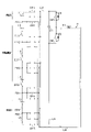
- FIG. 25 is an overall configuration diagram of a power converter according to the fourth embodiment,
- FIG. 26 is a flowchart showing the procedure of power transfer processing;
- FIG. 27 is a diagram showing a power supply mode when the supply source power storage unit and the supply destination power storage unit belong to different groups;
- FIG. 28 is a diagram showing a power supply mode when the supply source power storage unit and the supply destination power storage unit belong to different groups;
- FIG. 29 is a diagram showing a power supply mode when the supply source power storage unit and the supply destination power storage unit belong to the high potential group
- FIG. 30 is a diagram showing a power supply mode when the supply source power storage unit and the supply destination power storage unit belong to the high potential group
- FIG. 31 is a diagram showing a power supply mode when the supply source power storage unit and the supply destination power storage unit belong to the high potential group
- FIG. 32 is a diagram showing a power supply mode when the supply source power storage unit and the supply destination power storage unit belong to the high potential group
- FIG. 33 is a diagram showing a power supply mode when the supply source power storage unit and the supply destination power storage unit belong to the low potential group
- FIG. 34 is a diagram showing a power supply mode when the supply source power storage unit and the supply destination power storage unit belong to the low potential group
- FIG. 35 is a diagram showing a power feeding mode when the supply source power storage unit and the supply destination power storage unit belong to the low potential group
- FIG. 36 is a diagram showing a power supply mode when the supply source power storage unit and the supply destination power storage unit belong to the low potential group
- FIG. 37 is an overall configuration diagram of the power converter according to the fifth embodiment
- FIG. 38 is a flowchart showing the procedure of power transfer processing
- FIG. 39 is a diagram showing a power supply mode when the supply source power storage unit is adjacent to the high potential side of the supply destination power storage unit;
- FIG. 40 is a diagram showing a power supply mode when the supply source power storage unit is adjacent to the low potential side of the supply destination power storage unit;
- FIG. 41 is a diagram showing a power supply mode in the case where another power storage unit is interposed between the supply source power storage unit on the high potential side and the supply destination power storage unit on the low potential side,
- FIG. 42 is a diagram showing a power supply mode in the case where another power storage unit is interposed between the supply source power storage unit on the high potential side and the supply destination power storage unit on the low potential side,
- FIG. 43 is a diagram showing a power supply mode in the case where another power storage unit is interposed between the supply source power storage unit on the high potential side and the supply destination power storage unit on the low potential side,
- FIG. 41 is a diagram showing a power supply mode in the case where another power storage unit is interposed between the supply source power storage unit on the high potential side and the supply destination power storage unit on the low potential side
- FIG. 42 is a diagram showing a power supply mode in
- FIG. 44 is a diagram showing a power supply mode in the case where another power storage unit is interposed between the supply source power storage unit on the high potential side and the supply destination power storage unit on the low potential side
- FIG. 45 is a diagram showing a power supply mode in the case where another power storage unit is interposed between the supply source power storage unit on the low potential side and the supply destination power storage unit on the high potential side
- FIG. 46 is a diagram showing a power supply mode in the case where another power storage unit is interposed between the supply source power storage unit on the low potential side and the supply destination power storage unit on the high potential side
- FIG. 45 is a diagram showing a power supply mode in the case where another power storage unit is interposed between the supply source power storage unit on the low potential side and the supply destination power storage unit on the high potential side
- FIG. 46 is a diagram showing a power supply mode in the case where another power storage unit is interposed between the supply source power storage unit on the low potential side and the supply destination power storage unit on the high potential side
- FIG. 47 is a diagram showing a power supply mode in the case where another power storage unit is interposed between the supply source power storage unit on the low potential side and the supply destination power storage unit on the high potential side
- FIG. 48 is a diagram showing a power supply mode in the case where another power storage unit is interposed between the supply source power storage unit on the low potential side and the supply destination power storage unit on the high potential side
- FIG. 49 is an overall configuration diagram of a power converter according to the sixth embodiment
- FIG. 50 is a flowchart showing the procedure of power transfer processing
- FIG. 51 is a diagram showing a power supply mode in the case where another power storage unit is interposed between the supply source power storage unit on the high potential side and the supply destination power storage unit on the low potential side
- FIG. 52 is a diagram showing a power supply mode in the case where another power storage unit is interposed between the supply source power storage unit on the high potential side and the supply destination power storage unit on the low potential side
- FIG. 53 is a diagram showing a power supply mode in the case where another power storage unit is interposed between the supply source power storage unit on the low potential side and the supply destination power storage unit on the high potential side
- FIG. 54 is a diagram showing a power supply mode in the case where another power storage unit is interposed between the supply source power storage unit on the low potential side and the supply destination power storage unit on the high potential side
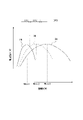
- FIG. 55 is a diagram showing the relationship between the transferred power, the number of phases, and the power conversion efficiency according to the seventh embodiment; FIG.
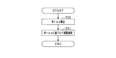
- FIG. 56 is a flowchart showing the procedure of phase number selection processing
- FIG. 57 is a diagram showing the configuration of a power storage unit according to another embodiment
- FIG. 58 is an overall configuration diagram of a power converter according to another embodiment
- FIG. 59 is an overall configuration diagram of a power converter according to another embodiment
- FIG. 60 is an overall configuration diagram of a power converter according to another embodiment
- FIG. 61 is an overall configuration diagram of a power converter according to another embodiment.
- the power conversion device of this embodiment is mounted on a vehicle such as a hybrid vehicle, an electric vehicle, or a fuel cell vehicle.
- Vehicles include, for example, passenger cars, buses, construction vehicles, and agricultural machinery vehicles.
- the power converter includes an assembled battery, an inverter 20, and a rotating electrical machine 30.
- the assembled battery includes a series connection body of power storage units.
- the power storage unit is a battery cell that is a single battery.
- the terminal voltage (for example, rated voltage) of each power storage unit is set to the same voltage.
- a battery cell for example, a secondary battery such as a lithium ion battery can be used.
- FIG. 1 shows an example in which the assembled battery includes six power storage units.
- the power storage units included in the assembled battery are referred to as first to sixth power storage units 11-16.
- the highest potential power storage unit having the highest potential is first power storage unit 11
- the lowest potential power storage unit having the lowest potential is sixth power storage unit 16 .
- the negative terminal of the first power storage unit 11 is connected to the positive terminal of the second power storage unit 12 via the first connection point PB1.
- the negative terminal of second power storage unit 12 is connected to the positive terminal of third power storage unit 13 via second connection point PB2.
- the negative terminal of third power storage unit 13 is connected to the positive terminal of fourth power storage unit 14 via third connection point PB3.
- the negative terminal of fourth power storage unit 14 is connected to the positive terminal of fifth power storage unit 15 via fourth connection point PB4.
- the negative terminal of fifth power storage unit 15 is connected to the positive terminal of sixth power storage unit 16 via fifth connection point PB5.
- the connection points PB1 to PB5 correspond to "battery connection points".
- All or part of the power storage units 11 to 16 that make up the assembled battery are replaceable. For example, when the remaining capacity of some of the power storage units 11 to 16 becomes low, some of the power storage units are replaced with fully charged power storage units. Further, for example, when some power storage units have deteriorated over time, some of the power storage units are replaced with power storage units that have not deteriorated over time (for example, new power storage units).
- the rotating electric machine 30 is a 3-phase synchronous machine and includes a 3-phase stator winding 31 that is star-connected.
- the stator windings 31 of each phase are arranged with an electrical angle shift of 120°.
- the rotary electric machine 30 is, for example, a permanent magnet synchronous machine.
- the rotary electric machine 30 is a vehicle-mounted main machine and serves as a driving power source for the vehicle.
- the inverter 20 has three phases of serially connected bodies of upper arm switches SWH and lower arm switches SWL.
- voltage-controlled semiconductor switching elements specifically IGBTs, are used as the switches SWH and SWL. Therefore, the high potential side terminal of each switch SWH and SWL is the collector, and the low potential side terminal is the emitter.
- Upper and lower arm diodes DH and DL as freewheel diodes are connected in anti-parallel to the upper and lower arm switches SWH and SWL.
- a first end of the stator winding 31 is connected to the emitter of the upper arm switch SWH and the collector of the lower arm switch SWL in each phase.
- the second ends of the stator windings 31 of each phase are connected at a neutral point O.
- the stator windings 31 of each phase are set to have the same number of turns.
- the stator windings 31 of each phase are set to have the same inductance, for example.
- the power conversion device 10 includes a high potential side path LP, a low potential side path LN and a capacitor 21 .
- the collector of the upper arm switch SWH of each phase and the positive terminal of the first power storage unit 11 are connected by a high potential side path LP.
- the emitter of the lower arm switch SWL of each phase and the negative terminal of the sixth power storage unit 16 are connected by a low potential side path LN.
- a capacitor 21 connects the collector of the upper arm switch SWH of each phase and the emitter of the lower arm switch SWL of each phase. Note that the capacitor 21 may be built in the inverter 20 or may be provided outside the inverter 20 .
- the power conversion device 10 includes a monitoring unit 40 and a control device 50 .
- the monitoring unit 40 monitors terminal voltage [V], remaining capacity [Ah], SOC, SOH, temperature, etc. of each of the power storage units 11 to 16 constituting the assembled battery. Monitoring information from the monitoring unit 40 is input to the control device 50 .
- the power converter 10 has a neutral point path LM.
- a neutral point path LM is connected to the neutral point O.
- the power converter 10 includes a positive switch SP and a negative switch SN.
- the positive switch SP and the negative switch SN are relays.
- the positive switch SP connects the positive terminal of the first power storage unit 11 and the high potential side path LP. By turning on the positive switch SP, the positive terminal of the first power storage unit 11 and the high potential side path LP are electrically connected. On the other hand, by turning off the positive switch SP, the positive terminal of the first power storage unit 11 and the high potential side path LP are electrically cut off.
- Negative switch SN connects the negative terminal of sixth power storage unit 16 and low potential side path LN. By turning on the negative switch SN, the negative terminal of the sixth power storage unit 16 and the low potential side path LN are electrically connected. On the other hand, by turning off the negative electrode switch SN, the negative electrode terminal of the sixth power storage unit 16 and the low potential side path LN are electrically cut off.
- the power converter includes first to fifth neutral point switches SM1 to SM5.
- each neutral switch SM1-SM5 is a relay.
- the n-th connection point PBn and the neutral point path LM are electrically connected.
- the n-th connection point PBn and the neutral point path LM are electrically cut off.
- the control device 50 is mainly composed of a microcomputer and functions as a control section.
- a microcomputer has a CPU.
- the functions provided by the microcomputer can be provided by software recorded in a physical memory device, a computer executing the software, only software, only hardware, or a combination thereof.
- the microcomputer is provided by an electronic circuit, which is hardware, it can be provided by a digital circuit including many logic circuits, or an analog circuit.
- a microcomputer executes a program stored in a non-transitory tangible storage medium as its own storage unit.
- the program includes a control program shown in FIG. 2 and the like.
- a method corresponding to the program is executed by executing the program.
- the storage unit is, for example, a non-volatile memory. Note that the program stored in the storage unit can be updated via a communication network such as the Internet, for example.
- the control device 50 performs switching control of the upper and lower arm switches SWH and SWL of each phase constituting the inverter 20 in order to feedback-control the control amount of the rotating electric machine 30 to the command value.
- the controlled variable is, for example, torque.
- the upper arm switch SWH and the lower arm switch SWL are alternately turned on.
- the control device 50 turns on or off the positive switch SP, the negative switch SN, and each of the neutral point switches SM1 to SM5, and is capable of communicating with the monitoring unit 40.
- the control device 50 performs power supply processing to reduce the difference between the capacity parameters of the power storage units 11-16.
- the capacity parameter is the terminal voltage [V], SOC, or remaining capacity [Ah] of the power storage unit.
- Control device 50 selects one power storage unit or a part of power storage units connected in series from power storage units 11 to 16 as a supply source power storage unit, and selects power storage units other than the supply source power storage unit from power storage units 11 to 16. , as a supply destination power storage unit. Based on the information acquired from the monitoring unit 40, the control device 50 selects, for example, the power storage unit having the largest capacity parameter among the power storage units 11 to 16 as the supply source power storage unit, and the remaining power storage units as the supply destination. Select as storage unit.
- the power supply process can reduce the difference in the capacity parameters of the power storage units 11 to 16, and thus equalize the capacity parameters of the power storage units 11 to 16.
- FIG. 2 shows a flowchart of power supply processing performed by the control device 50 .
- step S10 it is determined whether or not the selected supply source power storage unit includes the first power storage unit 11 or the sixth power storage unit 16.
- step S10 If an affirmative determination is made in step S10, the process proceeds to step S11 to perform the first control.
- the first control when the supply source power storage unit includes the first power storage unit 11 and when the supply source power storage unit includes the sixth power storage unit 16 will be described below.
- the supply source power storage unit includes the first power storage unit 11
- first and second power storage units 11 and 12 are replaced with new power storage units
- first and second power storage units 11 and 12 are selected as supply source power storage units
- third to third power storage units are selected as supply destination power storage units.
- 6 power storage units 13 to 16 will be described. Note that in FIG. 3 and the like, the three-phase configuration of the inverter 20 and the rotating electric machine 30 is simplified as a one-phase configuration for convenience.
- the first control when the first power storage unit 11 is included in the power storage unit of the supply source is the positive switch SP, the neutral point switch connected to the battery connection point on the lowest potential side of the power storage unit of the supply source, and the negative switch SP.
- the control device 50 turns on the positive switch SP, the negative switch SN, and the second neutral point switch SM2, and turns on the first, third to fifth neutral point switches SM1, SM3 to SM5. turn off.
- the second neutral point switch SM2 is a switch connected to the battery connection point on the lowest potential side of the supply destination power storage unit, that is, the second connection point PB2. Then, the control device 50 turns on the upper arm switch SWH and turns off the lower arm switch SWL. As a result, a current flows through a closed circuit including the first and second power storage units 11 and 12, the high potential side path LP, the upper arm switch SWH, the stator winding 31, and the neutral point path LM. Energy is stored. Thereafter, as shown in FIG. 4, the control device 50 turns off the upper arm switch SWH and turns on the lower arm switch SWL. As a result, a charging current based on the accumulated magnetic energy is supplied to the series connection body of the third to sixth power storage units 13-16.
- the supply source power storage unit includes the sixth power storage unit 16
- the fifth and sixth power storage units 15 and 16 are selected as the supply source power storage units and the first to fourth power storage units 11 to 14 are selected as the supply destination power storage units will be described.
- the positive electrode switch SP In the first control when the sixth power storage unit 16 is included in the power storage unit of the supply source, the positive electrode switch SP, the neutral point switch connected to the battery connection point on the highest potential side of the power storage unit of the supply source, and the negative electrode
- the control device 50 turns on the positive switch SP, the negative switch SN, and the fourth neutral point switch SM4, and turns on the first to third and fifth neutral point switches SM1 to SM3 and SM5. turn off.
- the fourth neutral point switch SM4 is a switch connected to the battery connection point on the highest potential side of the supply source power storage unit, that is, the fourth connection point PB4. Then, the control device 50 turns on the lower arm switch SWL and turns off the upper arm switch SWH. As a result, a current flows through a closed circuit including the fifth and sixth power storage units 15 and 16, the neutral point path LM, the stator winding 31, the lower arm switch SWL, and the low potential side path LN. Energy is stored. Thereafter, as shown in FIG. 6, the control device 50 turns off the lower arm switch SWL and turns on the upper arm switch SWH. As a result, a charging current based on the accumulated magnetic energy is supplied to the series connection body of the first to fourth power storage units 11-14.
- step S10 when it is determined in step S10 that the supply source power storage unit is sandwiched between the supply destination power storage units, the process proceeds to step S12 and the second control is performed. 7 to 10, the supply source power storage units are the second power storage unit 12 and the third power storage unit 13, and the supply destination power storage units are the first, fourth to sixth power storage units 14 to 16. The second control in this case will be described.
- the control device 50 turns on the positive switch SP, the negative switch SN, and the first neutral point switch SM1, and turns off the second to fifth neutral point switches SM2 to SM5.
- the first neutral point switch SM1 is a switch connected to the battery connection point on the highest potential side of the supply source power storage unit, that is, the first connection point PB1.
- the control device 50 turns on the lower arm switch SWL and turns off the upper arm switch SWH.
- magnetic energy is accumulated in the stator winding 31 using the second to sixth power storage units 12 to 16 as energy supply sources.
- the control device 50 turns on the upper arm switch SWH and turns off the lower arm switch SWL.
- the first power storage unit 11 is one of the first to sixth power storage units 11 to 16 that is on the higher potential side than the supply source power storage units (the second and third power storage units 12 and 13). Electric power is supplied from the second to sixth power storage units 12 to 16 to the first power storage unit 11 by alternately repeating the switching states shown in FIGS.
- the control device 50 turns on the positive switch SP, the negative switch SN, and the third neutral point switch SM3.
- the third neutral point switch SM3 is a switch connected to the battery connection point on the lowest potential side of the power storage unit of the supply source, that is, the third connection point PB3.
- the control device 50 turns on the upper arm switch SWH and turns off the lower arm switch SWL.
- magnetic energy is accumulated in stator winding 31 using first to third power storage units 11 to 13 as energy supply sources.
- the control device 50 turns off the upper arm switch SWH and turns on the lower arm switch SWL.
- the fourth to sixth power storage units 14 to 16 are power storage units on the lower potential side than the supply source power storage units (second and third power storage units 12 and 13) among the first to sixth power storage units 11 to 16. .
- electric power is supplied from the first to third power storage units 11-13 to the fourth to sixth power storage units 14-16.
- the voltages from the second and third power storage units 12 and 13 to the first and fourth to sixth power storage units 11 and 14 to 16 are switched. Power is supplied. In this case, power is discharged from second and third power storage units 12 and 13 in the switching state shown in FIG. 7 and the switching state shown in FIG. As a result, the remaining capacities of the second and third power storage units 12, 13 decrease, the remaining capacities of the first, fourth to sixth power storage units 11, 14-16 increase, and the capacities of the power storage units 11-16 increase. Parameter difference can be reduced. It should be noted that the power supply process may be executed while appropriately selecting the supply source and supply destination power storage units until the difference between the maximum value and the minimum value among the capacity parameters of the power storage units 11 to 16 becomes equal to or less than the threshold value. good.
- the second control in step S12 may be the control shown in FIGS. 11-14.
- the supply source power storage units are the second power storage unit 12 and the third power storage unit 13
- the supply destination power storage units are the first, fourth to fourth power storage units. 6 power storage units 14 to 16 are shown.
- the control device 50 turns on the positive switch SP, the negative switch SN, and the third neutral point switch SM3 to turn on the first, second, fourth, and fifth neutral point switches SM1 and SM2. , SM4 and SM5 are turned off.
- the third neutral point switch SM3 is a switch connected to the battery connection point on the lowest potential side of the power storage unit of the supply source, that is, the third connection point PB3.
- the control device 50 turns on the upper arm switch SWH and turns off the lower arm switch SWL. Magnetic energy is thereby accumulated in the stator windings 31 .
- the control device 50 turns off the upper arm switch SWH and turns on the lower arm switch SWL.
- the fourth to sixth power storage units 14 to 16 are power storage units on the lower potential side than the supply source power storage units (second and third power storage units 12 and 13) among the first to sixth power storage units 11 to 16. .
- electric power is supplied from the first to third power storage units 11-13 to the fourth to sixth power storage units 14-16.
- the control device 50 turns on the positive switch SP, the negative switch SN, and the first neutral point switch SM1.
- the first neutral point switch SM1 is a switch connected to the battery connection point on the highest potential side of the supply source power storage unit, that is, the first connection point PB1.
- the control device 50 turns off the upper arm switch SWH and turns on the lower arm switch SWL. Magnetic energy is thereby accumulated in the stator windings 31 .
- the control device 50 turns on the upper arm switch SWH and turns off the lower arm switch SWL. Thereby, a charging current based on the accumulated magnetic energy is supplied to first power storage unit 11 .
- the first power storage unit 11 is one of the first to sixth power storage units 11 to 16 that is on the higher potential side than the supply source power storage units (the second and third power storage units 12 and 13). Electric power is supplied from the second to sixth power storage units 12 to 16 to the first power storage unit 11 by alternately repeating the switching states shown in FIGS.
- the voltages from the second and third power storage units 12 and 13 to the first and fourth to sixth power storage units 11 and 14 to 16 are switched. Power is supplied. In this case, power is discharged from second and third power storage units 12 and 13 in the switching state shown in FIG. 11 and the switching state shown in FIG. As a result, the remaining capacities of the second and third power storage units 12, 13 decrease, the remaining capacities of the first, fourth to sixth power storage units 11, 14-16 increase, and the capacities of the power storage units 11-16 increase. Parameter difference can be reduced.
- the power converter includes first to fifth negative switches SN1 to SN5.
- each negative switch SN1-SN5 is a relay and is turned on or off by the controller 50.
- FIG. 15 the same reference numerals are given to the same configurations as those shown in FIG. 1 for the sake of convenience.
- the nth negative electrode switch SNn By turning off the nth negative electrode switch SNn, the negative electrode terminal of the n+1th power storage unit and the low potential side path LN are electrically cut off.
- the control device 50 performs the first control and the second control in the same manner as in the flowchart shown in FIG.
- the first control is the same control as the first control described in the first embodiment.
- the supply source power storage unit is the second power storage unit 12 and the third power storage unit 13, and the supply destination power storage units are the first, fourth to sixth power storage units 14 to 16.
- the second control in this case will be described.
- the control device 50 turns on the positive switch SP, the first neutral point switch SM1 and the second negative switch SN2, the second to fifth neutral point switches SM2 to SM5 and the first and second neutral point switches SM2 to SM5.
- the third to fifth negative switches SN1 and SN3 to SN5 are turned off.
- the control device 50 turns on the lower arm switch SWL and turns off the upper arm switch SWH.
- magnetic energy is accumulated in the stator winding 31 using the second and third power storage units 12 and 13 as energy supply sources.
- the control device 50 turns on the upper arm switch SWH and turns off the lower arm switch SWL.
- the control device 50 turns on the positive switch SP, the fifth negative switch SN1, and the third neutral switch SM3. Then, the control device 50 turns on the upper arm switch SWH and turns off the lower arm switch SWL. As a result, magnetic energy is accumulated in stator winding 31 using first to third power storage units 11 to 13 as energy supply sources. Thereafter, as shown in FIG. 19, the control device 50 turns off the upper arm switch SWH and turns on the lower arm switch SWL. As a result, a charging current based on the accumulated magnetic energy is supplied to the series connection body of the fourth to sixth power storage units 14-16. By alternately repeating the switching states shown in FIGS. 18 and 19, electric power is supplied from the first to third power storage units 11-13 to the fourth to sixth power storage units 14-16.
- the power conversion device includes first to fifth positive switches SP1 to SP5 instead of the first to fifth negative switches SN1 to SN5.
- each positive switch SP1-SP5 is a relay and is turned on or off by the control device 50.
- FIG. 20 the same reference numerals are assigned to the same configurations as those shown in FIG. 15 for convenience.
- the positive electrode terminal of the n-th power storage unit and the high potential side path LP are electrically connected.
- the positive electrode terminal of the nth power storage unit and the high potential side path LP are electrically cut off.
- the control device 50 performs the first control and the second control in the same manner as in the flowchart shown in FIG.
- the first control is the same control as the first control described in the first embodiment.
- the supply source power storage units are the third and fourth power storage units 13 and 14, and the supply destination power storage units are the first, second, fifth and sixth power storage units 11 and 12. , 15 and 16 will be described.
- the control device 50 turns on the third positive switch SP3, the negative switch SN and the fourth neutral switch SM4, and turns on the first, second, fourth and fifth positive switches SP1, SP2, SP4, SP5 and first to third, fifth neutral point switches SM1 to SM3, SM5 are turned off. Then, the control device 50 turns on the upper arm switch SWH and turns off the lower arm switch SWL. As a result, magnetic energy is accumulated in the stator winding 31 using the third and fourth power storage units 13 and 14 as energy supply sources. Thereafter, as shown in FIG. 22, the control device 50 turns off the upper arm switch SWH and turns on the lower arm switch SWL.
- charging current based on the accumulated magnetic energy is supplied to fifth and sixth power storage units 15 and 16 .
- power is supplied from the third and fourth power storage units 13 and 14 to the fifth and sixth power storage units 15 and 16 .
- the loss in the power conversion device is reduced and progress of deterioration of the power storage unit is suppressed.
- the control device 50 turns on the first positive switch SP1, the negative switch SN and the second neutral switch SM2. Then, the control device 50 turns off the upper arm switch SWH and turns on the lower arm switch SWL. As a result, magnetic energy is accumulated in the stator winding 31 using the third to sixth power storage units 13 to 16 as energy supply sources. After that, as shown in FIG. 24, the control device 50 turns on the upper arm switch SWH and turns off the lower arm switch SWL. As a result, a charging current based on the accumulated magnetic energy is supplied to the series connection body of first and second power storage units 11 and 12 . Electric power is supplied from the third to sixth power storage units 13 to 16 to the first and second power storage units 11 and 12 by alternately repeating the switching states shown in FIGS.
- the third and fourth power storage units 13 and 14 to the first, second, fifth and sixth power storage units 11 and 12 , 15, 16 are powered.
- the difference in the capacity parameter of each power storage unit 11-16 can be reduced.
- the power converter includes first to fourth positive switches SP1 to SP4, first to third negative switches SN1 to SN3, and an inter-battery switch SD.
- the positive switches SP1 to SP4, the negative switches SN1 to SN3, and the inter-battery switch SD are relays that are turned on or off by the controller 50.
- FIG. 25 the same reference numerals are given to the same configurations as those shown in FIG. 1 for convenience.
- the first to fourth power storage units 11 to 14 on the high potential side correspond to the high potential power storage units, and the remaining fifth and sixth power storage units. Portions 15 and 16 correspond to the low potential storage portion.
- the first positive electrode switch SP1 connects the positive electrode terminal of the first power storage unit 11 and the high potential side path LP.
- the positive electrode terminal of the n-th power storage unit and the high potential side path LP are electrically connected.
- the positive electrode terminal of the nth power storage unit and the high potential side path LP are electrically cut off.
- the mth negative switch SNm By turning on the mth negative switch SNm, the positive terminal of the m+4th power storage unit and the low potential side path LN are electrically connected.
- Third negative switch SN3 connects the negative terminal of sixth power storage unit 16 and low potential side path LN.
- the inter-battery switch SD connects the negative terminal of the fourth power storage unit 14 and the fourth connection point PB4. By turning on inter-battery switch SD, the negative terminal of fourth power storage unit 14 and fourth connection point PB4 are electrically connected. On the other hand, inter-battery switch SD is turned off, thereby electrically disconnecting the negative terminal of fourth power storage unit 14 from fourth connection point PB4. Note that inter-battery switch SD is provided not between the negative terminal of fourth power storage unit 14 and fourth connection point PB4, but between the positive terminal of fourth power storage unit 14 and third connection point PB3. good too. Further, in the present embodiment, the fourth power storage unit 14 corresponds to the "specific power storage unit".
- Control device 50 selects one power storage unit or a part of power storage units connected in series from among power storage units 11 to 16 as a supply source power storage unit, and selects one of power storage units 11 to 16 as a supply source power storage unit.
- One power storage unit other than the supply source power storage unit or a part of power storage units connected in series other than the supply source power storage unit is selected as the supply destination power storage unit.
- the control device 50 selects, for example, the power storage unit with the largest capacity parameter among the power storage units 11 to 16 as the supply source power storage unit, and selects the power storage unit with the smallest capacity parameter. is selected as the supply destination power storage unit.
- control device 50 controls one of the power storage units 11 to 16 other than the supply source power storage unit and the supply destination power storage unit or part of the power storage units connected in series other than the supply source power storage unit and the supply destination power storage unit.
- the power storage unit is selected as the temporary supply destination power storage unit.
- FIG. 26 shows the procedure of power supply processing performed by the control device 50 .
- step S20 a condition that the supply source power storage unit is in the high potential group and the supply destination power storage unit is in the low potential group, or that the supply source power storage unit is in the low potential group and the destination power storage unit is It is determined whether any one of the conditions that the part is in the high potential group is satisfied.
- the high potential group is a group of the first to fourth power storage units 11 to 14 on the higher potential side than the inter-battery switch SD among the power storage units 11 to 16 .
- the low potential side group is a group of fifth and sixth power storage units 15 and 16 on the low potential side of inter-battery switch SD among power storage units 11 to 16 .
- step S20 when the source power storage unit is the second power storage unit 12 and the destination power storage unit is the fifth power storage unit 15, or the source power storage unit is the fourth power storage unit 14 and the destination power storage unit is the fifth power storage unit. If it is power storage unit 15, an affirmative determination is made in step S20.
- step S21 determines whether or not another power storage unit is interposed between the supply source power storage unit and the supply destination power storage unit. For example, when the supply source power storage unit is the second power storage unit 12 and the supply destination power storage unit is the fifth power storage unit 15 , the third and fourth power storage units are placed between the second power storage unit 12 and the fifth power storage unit 15 . 13 and 14 intervene, affirmative determination is made in step S21. On the other hand, for example, when the supply source power storage unit is the fourth power storage unit 14 and the supply destination power storage unit is the fifth power storage unit 15, there is another power storage unit between the fourth power storage unit 14 and the fifth power storage unit 15. Since it does not intervene, a negative determination is made in step S21.
- step S21 If a negative determination is made in step S21, the process proceeds to step S22 to turn on the inter-battery switch SD. On the other hand, if the determination in step S21 is affirmative, the process proceeds to step S23 to turn off the inter-battery switch SD.
- the reason why the inter-battery switch SD is turned off is to prevent short-circuiting between the positive terminal and the negative terminal of the power storage unit when performing the first control in step S24.
- step S24 After the processing of step S22 or S23 is completed, the first control is performed in step S24.
- the supply source power storage unit is the second power storage unit 12
- the supply destination power storage unit is the fifth power storage unit 15
- an affirmative determination is made in step S21 will be described below with reference to FIGS.
- the control device 50 turns on the second positive electrode switch SP2, the second and fourth neutral point switches SM2 and SM4, and the second negative electrode switch SN2, thereby turning on the first, third, and fourth positive electrode switches.
- SP1, SP3 and SP4, the first and third negative switches SN1 and SN3, the first, third and fifth neutral switches SM1, SM3 and SM5, and the inter-battery switch SD are turned off.
- the control device 50 turns on the upper arm switch SWH and turns off the lower arm switch SWL.
- magnetic energy is accumulated in the stator winding 31 using the second power storage unit 12 as an energy supply source. After that, as shown in FIG.
- the control device 50 turns off the upper arm switch SWH and turns on the lower arm switch SWL. As a result, charging current based on the accumulated magnetic energy is supplied to fifth power storage unit 15 . Electric power is supplied from the second power storage unit 12 to the fifth power storage unit 15 by alternately turning on the upper and lower arm switches SWH and SWL.
- step S20 when it is determined in step S20 that one of the high potential side group and the low potential side group includes both the supply source power storage unit and the supply destination power storage unit, advances to step S25 to turn off the inter-battery switch SD. After that, the second control is performed in step S26. The second control will be described below.
- the control device 50 determines that the supply source power storage unit and the supply destination power storage unit are included in the high potential group will be described with reference to FIGS.
- the supply source power storage unit is the second power storage unit 12 and the supply destination power storage unit is the third power storage unit 13 .
- the control device 50 turns on the second positive electrode switch SP2, the second and fourth neutral point switches SM2 and SM4, and the second negative electrode switch SN2, thereby turning on the first, third, and fourth positive electrode switches.
- SP1, SP3 and SP4 the first, third and fifth neutral point switches SM1, SM3 and SM5, the first and third negative switches SN1 and SN3 and the inter-battery switch SD are turned off.
- first, fourth and sixth power storage units 11, 14 and 16 are disconnected from the system using neutral point path LM.
- the control device 50 turns on the upper arm switch SWH and turns off the lower arm switch SWL. As a result, magnetic energy is accumulated in the stator winding 31 using the second power storage unit 12 as an energy supply source.
- the control device 50 turns off the upper arm switch SWH and turns on the lower arm switch SWL. Thereby, the charging current based on the accumulated magnetic energy is supplied to the fifth power storage unit 15 selected by the control device 50 as the "temporary supply destination power storage unit". Electric power is supplied from the second power storage unit 12 to the fifth power storage unit 15 by alternately repeating the switching states shown in FIGS. In this case, since the inter-battery switch SD is turned off, even if the second and fourth neutral point switches SM2, SM4 are turned on, the positive terminal of the third power storage unit 13 and the negative terminal of the fourth power storage unit 14 can be prevented from being short-circuited.
- the control device 50 turns on the third positive switch SP3, the third and fourth neutral switches SM3 and SM4, and the second negative switch SN2 to turn on the first, second and fourth switches SN2.
- the positive switches SP1, SP2 and SP4, the first, second and fifth neutral switches SM1, SM2 and SM5, the first and third negative switches SN1 and SN3, and the inter-battery switch SD are turned off.
- the control device 50 turns off the upper arm switch SWH and turns on the lower arm switch SWL.
- magnetic energy is accumulated in the stator winding 31 using the fifth power storage unit 15 as an energy supply source.
- the control device 50 turns on the upper arm switch SWH and turns off the lower arm switch SWL. Thereby, the charging current based on the accumulated magnetic energy is supplied to the third power storage unit 13 .
- the switching states shown in FIGS. 31 and 32 power is supplied from fifth power storage unit 15 to third power storage unit 13 .
- the control device 50 determines that the supply source power storage unit and the supply destination power storage unit are included in the low potential group will be described with reference to FIGS.
- the fifth power storage unit 15 is the source power storage unit
- the sixth power storage unit 16 is the destination power storage unit
- the third power storage unit 13 is the temporary power storage unit.
- the control device 50 turns on the fourth neutral point switch SM4, the second negative switch SN2, the third positive switch SP3 and the fourth neutral point switch SM4 to 4
- the positive switches SP1, SP2 and SP4, the first, second and fifth neutral switches SM1, SM2 and SM5, the first and third negative switches SN1 and SN3 and the inter-battery switch SD are turned off.
- the control device 50 turns off the upper arm switch SWH and turns on the lower arm switch SWL.
- magnetic energy is accumulated in the stator winding 31 using the fifth power storage unit 15 as an energy supply source.
- the control device 50 turns on the upper arm switch SWH and turns off the lower arm switch SWL. Thereby, the charging current based on the accumulated magnetic energy is supplied to the third power storage unit 13 selected as the "temporary supply destination power storage unit". Electric power is supplied from the fifth power storage unit 15 to the third power storage unit 13 by alternately repeating the switching states shown in FIGS. In this case, since the inter-battery switch SD is turned off, even if the third and fourth neutral point switches SM2 and SM4 are turned on, the positive terminal and the negative terminal of the fourth power storage unit 14 are not short-circuited. can be prevented.
- the control device 50 turns on the third positive switch SP3, the third neutral point switch SM3, the fifth neutral point switch SM5, and the third negative switch SN3, thereby , fourth positive switches SP1, SP2, SP4, first, second, fourth neutral switches SM1, SM2, SM4, first and second negative switches SN1, SN2, and inter-battery switch SD are turned off. Then, the control device 50 turns on the upper arm switch SWH and turns off the lower arm switch SWL. As a result, magnetic energy is accumulated in the stator winding 31 using the third power storage unit 13 as an energy supply source. After that, as shown in FIG. 36, the control device 50 turns off the upper arm switch SWH and turns on the lower arm switch SWL. Thereby, a charging current based on the accumulated magnetic energy is supplied to sixth power storage unit 16 . Electric power is supplied from the third power storage unit 13 to the sixth power storage unit 16 by alternately repeating the switching states shown in FIGS.
- Power is supplied from the fifth power storage unit 15 to the sixth power storage unit 16 by performing the switching control of the upper and lower arm switches SWH and SWL of the inverter 20 described above.
- charging current does not flow to power storage units other than the supply source power storage unit and the supply destination power storage unit, so it is possible to reduce loss in the power conversion device and to suppress progress of deterioration of the power storage unit.
- the power converter includes first to fifth positive switches SP1 to SP5 and first to fifth negative switches SN1 to SN5.
- each of the positive switches SP1-SP5 and each of the negative switches SN1-SN5 is a relay and is turned on or off by the controller 50.
- FIG. 37 the same reference numerals are given to the same configurations as those shown in FIG. 1 for the sake of convenience.
- the positive electrode terminal of the n-th power storage unit and the high potential side path LP are electrically connected.
- the positive electrode terminal of the nth power storage unit and the high potential side path LP are electrically cut off.
- the nth negative switch SNn connects the negative terminal of the n+1th power storage unit and the low potential side path LN.
- the negative terminal of the n+1th power storage unit and the low potential side path LN are electrically connected.
- the negative electrode terminal of the n+1th power storage unit and the low potential side path LN are electrically cut off.
- Control device 50 selects one power storage unit or a part of power storage units connected in series from among power storage units 11 to 16 as a supply source power storage unit, and selects one of power storage units 11 to 16 as a supply source power storage unit.
- One power storage unit other than the supply source power storage unit or a part of power storage units connected in series other than the supply source power storage unit is selected as the supply destination power storage unit.
- FIG. 38 shows the procedure of power supply processing performed by the control device 50 .
- step S30 it is determined whether or not the supply source power storage unit and the supply destination power storage unit are adjacent to each other. For example, when the supply source power storage unit is the second power storage unit 12 and the supply destination power storage unit is the third power storage unit 13, an affirmative determination is made in step S30, the supply source power storage unit is the second power storage unit 12, and the supply source power storage unit is the second power storage unit 12. If the previous power storage unit is the sixth power storage unit 16, a negative determination is made in step S30.
- step S30 If the determination in step S30 is affirmative, the process proceeds to step S31 to perform the first control.
- the first control will be described below.
- the control device 50 determines that the supply source power storage unit is on the higher potential side than the supply destination power storage unit will be described.
- the source power storage unit is the second power storage unit 12 and the destination power storage unit is the third power storage unit 13 .
- the controller 50 turns on the second positive switch SP2, the second neutral switch SM2 and the second negative switch SN2, and turns on the first, third to fifth positive switches SP1, SP3 to SP5, the first, third, The fifth neutral point switches SM1, SM3, SM5 and the first, third to fifth negative switches SN1, SN3 to SN5 are turned off. Then, the control device 50 turns on the upper arm switch SWH and turns off the lower arm switch SWL. As a result, magnetic energy is accumulated in the stator winding 31 using the second power storage unit 12 as an energy supply source. After that, the control device 50 turns off the upper arm switch SWH and turns on the lower arm switch SWL. Thereby, the charging current based on the accumulated magnetic energy is supplied to the third power storage unit 13 . Electric power is supplied from the second power storage unit 12 to the third power storage unit 13 by alternately turning on the upper and lower arm switches SWH and SWL. Thereby, the difference between the capacity parameters of second and third power storage units 12 and 13 can be reduced.
- the control device 50 determines that the supply source power storage unit is on the lower potential side than the supply destination power storage unit will be described.
- the source power storage unit is the fourth power storage unit 14 and the destination power storage unit is the third power storage unit 13 .
- the control device 50 turns on the third negative switch SN3, the third neutral switch SM3, and the third positive switch SP3, and the first, second, fourth, and fifth positive switches SP1, SP2, SP4, SP5, and the third positive switch SP1, SP2, SP4, SP5.
- the first, second, fourth and fifth neutral switches SM1, SM2, SM4 and SM5 and the first, second, fourth and fifth negative switches SN1, SN2, SN4 and SN5 are turned off.
- the control device 50 turns off the upper arm switch SWH and turns on the lower arm switch SWL.
- magnetic energy is accumulated in the stator winding 31 using the fourth power storage unit 14 as an energy supply source.
- the controller 50 turns on the upper arm switch SWH and turns off the lower arm switch SWL.
- the charging current based on the accumulated magnetic energy is supplied to the third power storage unit 13 .
- Electric power is supplied from the fourth power storage unit 14 to the third power storage unit 13 by alternately turning on the upper and lower arm switches SWH and SWL. Thereby, the difference between the capacity parameters of the third and fourth power storage units 13 and 14 can be reduced.
- step S30 if a negative determination is made in step S30, the process proceeds to step S32 to perform the second control.
- the second control will be described below.
- the control device 50 determines that the supply source power storage unit is on the higher potential side than the supply destination power storage unit will be described with reference to FIGS.
- the source power storage unit is the second power storage unit 12 and the destination power storage unit is the sixth power storage unit 16 .
- the control device 50 turns on the second positive switch SP2, the second neutral switch SM2 and the fourth negative switch SN4, and turns on the first, third to fifth positive switches SP1, SP3 to SP5. , the first, third to fifth neutral point switches SM1, SM3 to SM5, and the first to third, fifth negative electrode switches SN1 to SN3, SN5 are turned off. Then, the control device 50 turns on the upper arm switch SWH and turns off the lower arm switch SWL. As a result, magnetic energy is accumulated in the stator winding 31 using the second power storage unit 12 as an energy supply source. After that, as shown in FIG. 42, the control device 50 turns off the upper arm switch SWH and turns on the lower arm switch SWL.
- the charging current based on the accumulated magnetic energy is supplied to the intermediate power storage units, which are the third to fifth power storage units 13-15.
- the intermediate power storage units which are the third to fifth power storage units 13-15.
- the control device 50 turns on the third positive switch SP3, the fifth neutral switch SM5, and the fifth negative switch SN5, thereby turning on the first, second, fourth, and fifth positive switches.
- SP1, SP2, SP4, SP5, first to fourth neutral point switches SM1 to SM4, and first to fourth negative switches SN1 to SN4 are turned off.
- the control device 50 turns on the upper arm switch SWH and turns off the lower arm switch SWL.
- magnetic energy is accumulated in the stator winding 31 using the intermediate power storage unit as an energy supply source.
- the control device 50 turns off the upper arm switch SWH and turns on the lower arm switch SWL.
- a charging current based on the accumulated magnetic energy is supplied to sixth power storage unit 16 .
- power is supplied from the intermediate power storage unit to sixth power storage unit 16 .
- Power is supplied from the second power storage unit 12 to the sixth power storage unit 16 by performing the switching control of the upper and lower arm switches SWH and SWL of the inverter 20 described above. Thereby, the difference between the capacity parameters of the second and sixth power storage units 12 and 16 can be reduced.
- the above-described second control is a control in which power is supplied from the intermediate power storage unit to the supply destination power storage unit after power is supplied from the supply source power storage unit to the intermediate power storage unit.
- the present invention is not limited to this, and may be the second control in which power is supplied from the supply source power storage unit to the intermediate power storage unit after power is supplied from the intermediate power storage unit to the supply destination power storage unit.
- the switching states shown in FIGS. 43 and 44 may be alternately repeated. Even in this case, the difference between the capacity parameters of second and sixth power storage units 12 and 16 can be reduced.
- the control device 50 determines that the supply source power storage unit is on the lower potential side than the supply destination power storage unit will be described with reference to FIGS.
- the sixth power storage unit 16 is the supply source power storage unit
- the second power storage unit 12 is the destination power storage unit.
- the control device 50 turns on the fifth negative switch SN5, the fifth neutral switch SM5 and the third positive switch SP3, and turns on the first, second, fourth and fifth positive switches SP1, SP2, SP4, SP5, first to fourth neutral point switches SM1 to SM4, and first to fourth negative switches SN1 to SN4 are turned off. Then, the control device 50 turns off the upper arm switch SWH and turns on the lower arm switch SWL. As a result, magnetic energy is accumulated in the stator winding 31 using the sixth power storage unit 16 as an energy supply source. Thereafter, as shown in FIG. 46, the control device 50 turns on the upper arm switch SWH and turns off the lower arm switch SWL.
- the charging current based on the accumulated magnetic energy is supplied to the intermediate power storage units, which are the third to fifth power storage units 13-15.
- the intermediate power storage units which are the third to fifth power storage units 13-15.
- the controller 50 turns on the fourth negative switch SN4, the second neutral switch SM2, and the second positive switch SP2 to turn on the first, third to fifth positive switches SP1, SP3. , SP5, the first, third to fifth neutral point switches SM1, SM3 to SM5, and the first to third and fifth negative switches SN1 to SN3, SN5 are turned off. Then, the control device 50 turns off the upper arm switch SWH and turns on the lower arm switch SWL. As a result, magnetic energy is accumulated in the stator winding 31 using the intermediate power storage unit as an energy supply source. Thereafter, as shown in FIG. 48, the control device 50 turns on the upper arm switch SWH and turns off the lower arm switch SWL. Thereby, a charging current based on the accumulated magnetic energy is supplied to second power storage unit 12 . By alternately repeating the switching states shown in FIGS. 47 and 48 , power is supplied from the intermediate power storage unit to second power storage unit 12 .
- Power is supplied from the sixth power storage unit 16 to the second power storage unit 12 by performing the switching control of the upper and lower arm switches SWH and SWL of the inverter 20 described above. Thereby, the difference between the capacity parameters of the second and sixth power storage units 12 and 16 can be reduced.
- the above-described second control is a control in which power is supplied from the intermediate power storage unit to the supply destination power storage unit after power is supplied from the supply source power storage unit to the intermediate power storage unit.
- the present invention is not limited to this, and may be the second control in which power is supplied from the supply source power storage unit to the intermediate power storage unit after power is supplied from the intermediate power storage unit to the supply destination power storage unit.
- the switching states shown in FIGS. 47 and 48 are alternately repeated, the switching states shown in FIGS. 45 and 46 may be alternately repeated. Even in this case, the difference between the capacity parameters of second and sixth power storage units 12 and 16 can be reduced.
- the power converter includes first to fifth positive switches SP1 to SP5, first to fifth negative switches SN1 to SN5, and first to fourth inter-battery switches SD1.
- the positive switches SP1 to SP5, the negative switches SN1 to SN5, and the inter-battery switches SD1 to SD4 are relays that are turned on or off by the controller 50.
- FIG. 49 the same reference numerals are given to the same configurations as those shown in FIG. 1 for convenience.
- the first positive switch SP1 connects the positive terminal of the first power storage unit and the high potential side path LP.
- the n ⁇ 1th connection point PBn ⁇ 1 and the high potential side path LP are electrically connected.
- the n ⁇ 1th connection point PBn ⁇ 1 and the high potential side path LP are electrically cut off.
- the fifth negative switch SN5 connects the negative terminal of the sixth power storage unit and the low potential side path LN.
- the m+1th connection point PBm+1 and the low potential side path LN are electrically connected.
- the m+1th connection point PBm+1 and the low potential side path LN are electrically cut off.
- the m-th inter-battery switch SDm connects the negative terminal of the m+1-th power storage unit and the m+1-th connection point PBm+1.
- the negative terminal of the m+1-th power storage unit and the m+1-th connection point PBm+1 are electrically connected.
- the m-th inter-battery switch SDm is turned off, the negative terminal of the m+1-th power storage unit and the m+1-th connection point PBm+1 are electrically disconnected.
- the m-th inter-battery switch SDm is provided not between the negative terminal of the m+1-th power storage unit and the m+1-th connection point PBm+1, but between the positive terminal of the m+1-th power storage unit and the m-th connection point PBm. good too.
- Control device 50 selects one power storage unit or a part of power storage units connected in series from among power storage units 11 to 16 as a supply source power storage unit, and selects one of power storage units 11 to 16 as a supply source power storage unit.
- One power storage unit other than the supply source power storage unit or a part of power storage units connected in series other than the supply source power storage unit is selected as the supply destination power storage unit.
- FIG. 50 shows the procedure of power supply processing performed by the control device 50 .
- step S40 the same processing as in step S30 of FIG. 38 is performed.
- step S40 the process proceeds to step S41 to turn on the inter-battery switch between the supply source power storage unit and the supply destination power storage unit.
- the first inter-battery switch SD1 is turned on.
- the supply source power storage units are the second and third power storage units 12 and 13 and the supply destination power storage units are the fourth and fifth power storage units 14 and 15, the first to third battery switches SD1 to Turn on SD3.
- step S42 the same first control as in step S31 of FIG. 38 is performed.
- FIG. 39 shows an example of the switch driving mode when it is determined that the supply source power storage unit is adjacent to the high potential side of the supply destination power storage unit.
- FIG. 40 shows an example of how the switches are driven when it is determined that they are adjacent to each other.
- step S40 determines whether a negative determination is made in step S40 or not. If a negative determination is made in step S40, the process proceeds to step S43 to perform the second control.
- the second control will be described below.
- the control device 50 determines that the supply source power storage unit is on the higher potential side than the supply destination power storage unit will be described.
- the source power storage unit is the second power storage unit 12 and the destination power storage unit is the fifth power storage unit 15 .
- the third and fourth power storage units 13 and 14 correspond to the "intermediate power storage unit".
- the control device 50 switches the second positive switch SP2, the second and fourth neutral switches SM2 and SM4, the fourth negative switch SN4, and the first and fourth inter-battery switches SD1 and SD4.
- 1st, 3rd to 5th positive switches SP1, SP3 to SP5, 1st, 3rd, 5th neutral switches SM1, SM3, SM5, 1st, 2nd, 3rd, 5th negative switches SN1, SN2, SN3, SN5 and the second and third inter-battery switches SD2, SD3 are turned off.
- the first and fourth inter-battery switches SD1 and SD4 are connected at second to fourth connection points PB2 between the second power storage unit 12, which is the supply source power storage unit, and the fifth power storage unit 15, which is the supply destination power storage unit. to PB4.
- the control device 50 turns on the upper arm switch SWH and turns off the lower arm switch SWL.
- magnetic energy is accumulated in the stator winding 31 using the second power storage unit 12 as an energy supply source.
- the control device 50 turns off the upper arm switch SWH and turns on the lower arm switch SWL.
- charging current based on the accumulated magnetic energy is supplied to fifth power storage unit 15 .
- Electric power is supplied from the second power storage unit 12 to the fifth power storage unit 15 by alternately repeating the switching states shown in FIGS. Thereby, the difference between the capacitance parameters of the second and fifth power storage units 12 and 15 can be reduced.
- the second and third inter-battery switches SD2 and SD3 are turned off, even if the second and fourth neutral point switches SM2 and SM4 are turned on, the positive terminal of the third power storage unit 13 and the third 4 can be prevented from being short-circuited with the negative terminal of power storage unit 14 . Only one of the second and third inter-battery switches SD2 and SD3 may be turned off.
- the supply source power storage unit is the first and second power storage units 11 and 12 instead of the second power storage unit 12, and the supply destination power storage units are the fifth and sixth power storage units 15 and 16 instead of the fifth power storage unit 15.
- the inter-battery switch that is turned off in the second control is at least one of the second and third inter-battery switches SD2 and SD3.
- the second and third inter-battery switches SD2 and SD3 are connected to the second power storage unit 12, which is the power storage unit on the lowest potential side of the supply source power storage unit, and the fifth power storage unit, which is the power storage unit on the highest potential side of the supply destination power storage unit. It is an inter-battery switch between the second to fourth connection points PB2 to PB4 existing between the power storage unit 15 and the storage unit 15 .
- the control device 50 determines that the supply source power storage unit is on the lower potential side than the supply destination power storage unit will be described.
- the supply source power storage units are the fifth and sixth power storage units 15 and 16 and the supply destination power storage unit is the first power storage unit 11 .
- the second to fourth power storage units 12 to 14 correspond to the "intermediate power storage unit".
- the control device 50 turns on the fifth negative switch SN5, the first neutral switch SM1, the fourth neutral switch SM4, and the first positive switch SP1, and the second to fifth positive switches SP1 are turned on.
- SP2 to SP5 second, third and fifth neutral point switches SM2, SM3 and SM5, first to fourth negative switches SN1 to SN4, and first to third inter-battery switches SD1 to SD3 are turned off.
- the first to third inter-battery switches SD1 to SD3 exist between the fifth power storage unit 15, which is the power storage unit on the highest potential side of the supply source power storage unit, and the first power storage unit 11, which is the supply destination power storage unit. It is an inter-battery switch between the first to fourth connection points PB1 to PB4.
- the control device 50 turns off the upper arm switch SWH and turns on the lower arm switch SWL.
- magnetic energy is accumulated in the stator winding 31 using the fifth and sixth power storage units 15 and 16 as energy supply sources.
- the control device 50 turns on the upper arm switch SWH and turns off the lower arm switch SWL.
- a charging current based on the accumulated magnetic energy is supplied to first power storage unit 11 .
- electric power is supplied from the fifth and sixth power storage units 15 and 16 to the first power storage unit 11 .
- the difference between the capacitance parameters of the second and fifth power storage units 12 and 15 can be reduced.
- first to third inter-battery switches SD1 to SD3 are turned off, even if the first and fourth neutral point switches SM1 and SM4 are turned on, the positive terminal of the second power storage unit 12 and the 4 can be prevented from being short-circuited with the negative terminal of power storage unit 14 .
- first to third inter-battery switches SD1 to SD3 only one or two inter-battery switches may be turned off.
- the inter-battery switches turned off in the second control are the second and third inter-battery switches SD2, at least one of SD3;
- the second and third inter-battery switches SD2 and SD3 are connected to the fifth power storage unit 15, which is the highest potential power storage unit of the supply source power storage unit, and the second power storage unit, which is the lowest potential power storage unit of the supply destination power storage unit. It is an inter-battery switch between the second to fourth connection points PB2 to PB4 existing between the power storage unit 12 and the power storage unit 12 .
- the seventh embodiment will be described below with reference to the drawings, focusing on differences from the first embodiment.
- the control device 50 of the present embodiment is configured such that the number of phases of the stator winding 31 through which current flows is the number of phases that maximizes the power conversion efficiency when power is supplied from the power storage unit of the supply source to the power storage unit of the supply destination. , the switching control of the inverter 20 is performed.
- FIG. 55 shows the relationship between the power conversion efficiency and the transfer power for each phase number of the stator winding 31 when current flows from the supply source power storage unit to the supply destination power storage unit via the inverter 20 and the neutral point path LM.
- the solid line shows the case where the number of phases of the stator winding 31 through which the current flows is one
- the dashed line shows the case where the number of phases of the stator winding 31 through which the current flows is two
- the dashed line shows the case where the stator winding 31 through which the current flows.
- a case in which the winding 31 has three phases is shown. The greater the number of phases of the stator winding 31 through which the current flows, the greater the power exchanged and received at which the power conversion efficiency is maximized.
- the maximum efficient power Wmax1 when the number of phases of the stator winding 31 through which current flows is one is smaller than the maximum efficient power Wmax2 when the number of phases of the stator winding 31 through which current flows is two. Further, the maximum efficient power Wmax2 when the number of phases of the stator winding 31 through which current flows is two is smaller than the maximum efficient power Wmax3 when the number of phases of the stator winding 31 through which current flows is three.
- FIG. 56 shows the procedure of phase number selection processing executed by the control device 50 .
- step S50 the power Wreq transferred from the supply source power storage unit to the supply destination power storage unit is calculated. Specifically, first, the difference in remaining capacity between the supply source power storage unit and the supply destination power storage unit is calculated. Then, the transfer power Wreq is calculated by dividing the calculated remaining capacity difference by the target time. In this case, the greater the difference in the remaining capacity or the shorter the target time, the greater the calculated transfer power Wreq.
- step S51 the number of phases is selected based on the calculated transfer power Wreq. Specifically, when the transferred power Wreq is within the range of the first region DP1 shown in FIG. 44, one phase is selected.
- the first region DP1 is a region of power transmission and reception in which the power conversion efficiency in the case of one phase is higher than the power conversion efficiency in the case of the other number of phases.
- the second region DP2 is a region of transferred power in which the power conversion efficiency in the case of two phases is higher than the power conversion efficiency in the case of other phases.
- the third region DP3 is a region of power transmission and reception in which the power conversion efficiency in the case of three phases is higher than the power conversion efficiency in the case of other phases.
- the control device 50 performs switching control to supply current to the stator windings 31 of the selected number of phases. For example, when 2-phase or 3-phase is selected, the upper and lower arm switches SWH and SWL for 2-phase or 3-phase are synchronously turned on and off. Thereby, the power conversion efficiency can be improved when the power supply process is executed.
- the storage unit may be a storage battery connected in parallel as shown in FIGS. 57 and 58 .
- FIG. 57 shows a modification of the configuration of FIG. 1
- FIG. 58 shows a modification of the configuration of FIG. Note that the number of parallel connections is not limited to two, and may be three or more.
- FIG. 58 shows a configuration in which a first inter-battery switch SD1 is provided between the negative terminal of first power storage unit 11 and first connection point PB1.
- the number of power storage units is not limited to six, and may be, for example, four as shown in FIGS. 58, 60 and 61, or five as shown in FIG. 59 shows a modification of the configuration of FIG. 25, FIG. 60 shows a modification of the configuration of FIG. 15, and FIG. 61 shows a modification of the configuration of FIG.
- the power storage unit is not limited to one storage battery, and may be a series connection of a plurality of storage batteries.
- the number of series connections is not limited to two, and may be three or more.
- the number of the storage batteries which comprise each electrical storage part may differ.
- the power storage unit is not limited to a storage battery, and may be, for example, a capacitor (for example, an electric double layer capacitor).
- the upper and lower arm switches that constitute the inverter are not limited to IGBTs, but may be, for example, N-channel MOSFETs with built-in body diodes. In this case, the high potential side terminal becomes the drain and the low potential side terminal becomes the source.
- the positive electrode switch, negative electrode switch, neutral point switch, and inter-battery switch are not limited to relays, and may be, for example, a pair of N-channel MOSFETs or IGBTs whose sources are connected to each other.
- the rotating electric machine and the inverter may be those other than 3-phase, such as 5-phase or 7-phase.
- the mobile object on which the power conversion device is mounted is not limited to a vehicle, and may be, for example, an aircraft or a ship. Further, the power conversion device is not limited to a device mounted on a moving body, and may be a stationary device.
- the controller and techniques described in this disclosure can be performed by a dedicated computer provided by configuring a processor and memory programmed to perform one or more functions embodied by a computer program; may be implemented.
- the controls and techniques described in this disclosure may be implemented by a dedicated computer provided by configuring the processor with one or more dedicated hardware logic circuits.
- the control units and techniques described in this disclosure can be implemented by a combination of a processor and memory programmed to perform one or more functions and a processor configured by one or more hardware logic circuits. It may also be implemented by one or more dedicated computers configured.
- the computer program may also be stored as computer-executable instructions on a computer-readable non-transitional tangible recording medium.
Landscapes
- Engineering & Computer Science (AREA)
- Power Engineering (AREA)
- Transportation (AREA)
- Mechanical Engineering (AREA)
- Life Sciences & Earth Sciences (AREA)
- Sustainable Development (AREA)
- Sustainable Energy (AREA)
- Charge And Discharge Circuits For Batteries Or The Like (AREA)
- Dc-Dc Converters (AREA)
- Secondary Cells (AREA)
- Inverter Devices (AREA)
Abstract
電力変換装置は、直列接続される3つ以上の蓄電部(11~16)に適用される。電力変換装置は、ステータ巻線(31)を有する回転電機(30)と、上,下アームスイッチ(SWH,SWL)を有し、ステータ巻線と蓄電部とを接続するインバータ(20)と、上アームスイッチの高電位側端子に接続された高電位側経路(LP)と、下アームスイッチの低電位側端子に接続された低電位側経路(LN)と、ステータ巻線の中性点に接続された中性点経路(LM)と、各蓄電部のうち隣り合う蓄電部の正極端子と負極端子との電池接続点(PB1~PB5)に対応して個別に設けられ、電池接続点と中性点経路とを接続する中性点スイッチ(SM1~SM5)と、を備える。
Description
本出願は、2021年8月5日に出願された日本出願番号2021-129197号に基づくもので、ここにその記載内容を援用する。
本開示は、電力変換装置に関する。
従来、特許文献1に記載されているように、複数の単位蓄電池の直列接続体と、絶縁型のDCDCコンバータと、補助バッテリとを備える充電均等化システムが知られている。DCDCコンバータは、各単位蓄電池に対応して個別に設けられ、出力側が単位蓄電池に接続され、入力側が補助バッテリに接続されている。DCDCコンバータが駆動されることにより、補助バッテリから単位蓄電池へと電力が供給される。これにより、各単位蓄電池の残容量を均等化することができる。
特許文献1に記載のシステムでは、単位蓄電池ごとにDCDCコンバータが必要になる。このため、システムが複雑化する懸念がある。
本開示は、構成の簡素化を図ることができる電力変換装置を提供することを主たる目的とする。
本開示は、直列接続される3つ以上の蓄電部に適用される電力変換装置において、
ステータ巻線を有する回転電機と、
上,下アームスイッチを有し、前記ステータ巻線と前記蓄電部とを接続するインバータと、
前記上アームスイッチの高電位側端子に接続された高電位側経路と、
前記下アームスイッチの低電位側端子に接続された低電位側経路と、
前記ステータ巻線の中性点に接続された中性点経路と、
前記各蓄電部のうち隣り合う蓄電部の正極端子と負極端子との電池接続点に対応して個別に設けられ、前記電池接続点と前記中性点経路とを接続する中性点スイッチと、
を備える。
ステータ巻線を有する回転電機と、
上,下アームスイッチを有し、前記ステータ巻線と前記蓄電部とを接続するインバータと、
前記上アームスイッチの高電位側端子に接続された高電位側経路と、
前記下アームスイッチの低電位側端子に接続された低電位側経路と、
前記ステータ巻線の中性点に接続された中性点経路と、
前記各蓄電部のうち隣り合う蓄電部の正極端子と負極端子との電池接続点に対応して個別に設けられ、前記電池接続点と前記中性点経路とを接続する中性点スイッチと、
を備える。
本開示では、各蓄電部のうち供給元蓄電部から供給先蓄電部への電力供給に、各電池接続点に対応して個別に設けられた中性点スイッチと、中性点経路とが備えられるとともに、ステータ巻線及びインバータが流用される。これにより、供給元蓄電部から供給先蓄電部へと電力を供給する構成の簡素化を図ることができる。
本開示についての上記目的およびその他の目的、特徴や利点は、添付の図面を参照しながら下記の詳細な記述により、より明確になる。その図面は、
図1は、第1実施形態に係る電力変換装置の全体構成図であり、
図2は、電力移動処理の手順を示すフローチャートであり、
図3は、供給元蓄電部が高電位側の端になる場合における給電態様を示す図であり、
図4は、供給元蓄電部が高電位側の端になる場合における給電態様を示す図であり、
図5は、供給元蓄電部が低電位側の端になる場合における給電態様を示す図であり、
図6は、供給元蓄電部が低電位側の端になる場合における給電態様を示す図であり、
図7は、供給元蓄電部が供給先蓄電部に挟まれる場合における給電態様を示す図であり、
図8は、供給元蓄電部が供給先蓄電部に挟まれる場合における給電態様を示す図であり、
図9は、供給元蓄電部が供給先蓄電部に挟まれる場合における給電態様を示す図であり、
図10は、供給元蓄電部が供給先蓄電部に挟まれる場合における給電態様を示す図であり、
図11は、供給元蓄電部が供給先蓄電部に挟まれる場合における給電態様を示す図であり、
図12は、供給元蓄電部が供給先蓄電部に挟まれる場合における給電態様を示す図であり、
図13は、供給元蓄電部が供給先蓄電部に挟まれる場合における給電態様を示す図であり、
図14は、供給元蓄電部が供給先蓄電部に挟まれる場合における給電態様を示す図であり、
図15は、第2実施形態に係る電力変換装置の全体構成図であり、
図16は、供給元蓄電部が供給先蓄電部に挟まれる場合における給電態様を示す図であり、
図17は、供給元蓄電部が供給先蓄電部に挟まれる場合における給電態様を示す図であり、
図18は、供給元蓄電部が供給先蓄電部に挟まれる場合における給電態様を示す図であり、
図19は、供給元蓄電部が供給先蓄電部に挟まれる場合における給電態様を示す図であり、
図20は、第3実施形態に係る電力変換装置の全体構成図であり、
図21は、供給元蓄電部が供給先蓄電部に挟まれる場合における給電態様を示す図であり、
図22は、供給元蓄電部が供給先蓄電部に挟まれる場合における給電態様を示す図であり、
図23は、供給元蓄電部が供給先蓄電部に挟まれる場合における給電態様を示す図であり、
図24は、供給元蓄電部が供給先蓄電部に挟まれる場合における給電態様を示す図であり、
図25は、第4実施形態に係る電力変換装置の全体構成図であり、
図26は、電力移動処理の手順を示すフローチャートであり、
図27は、供給元蓄電部と供給先蓄電部とが異なるグループに属する場合における給電態様を示す図であり、
図28は、供給元蓄電部と供給先蓄電部とが異なるグループに属する場合における給電態様を示す図であり、
図29は、供給元蓄電部と供給先蓄電部とが高電位グループに属する場合における給電態様を示す図であり、
図30は、供給元蓄電部と供給先蓄電部とが高電位グループに属する場合における給電態様を示す図であり、
図31は、供給元蓄電部と供給先蓄電部とが高電位グループに属する場合における給電態様を示す図であり、
図32は、供給元蓄電部と供給先蓄電部とが高電位グループに属する場合における給電態様を示す図であり、
図33は、供給元蓄電部と供給先蓄電部とが低電位グループに属する場合における給電態様を示す図であり、
図34は、供給元蓄電部と供給先蓄電部とが低電位グループに属する場合における給電態様を示す図であり、
図35は、供給元蓄電部と供給先蓄電部とが低電位グループに属する場合における給電態様を示す図であり、
図36は、供給元蓄電部と供給先蓄電部とが低電位グループに属する場合における給電態様を示す図であり、
図37は、第5実施形態に係る電力変換装置の全体構成図であり、
図38は、電力移動処理の手順を示すフローチャートであり、
図39は、供給元蓄電部が供給先蓄電部の高電位側に隣接する場合における給電態様を示す図であり、
図40は、供給元蓄電部が供給先蓄電部の低電位側に隣接する場合における給電態様を示す図であり、
図41は、高電位側の供給元蓄電部と低電位側の供給先蓄電部との間に他の蓄電部が介在する場合における給電態様を示す図であり、
図42は、高電位側の供給元蓄電部と低電位側の供給先蓄電部との間に他の蓄電部が介在する場合における給電態様を示す図であり、
図43は、高電位側の供給元蓄電部と低電位側の供給先蓄電部との間に他の蓄電部が介在する場合における給電態様を示す図であり、
図44は、高電位側の供給元蓄電部と低電位側の供給先蓄電部との間に他の蓄電部が介在する場合における給電態様を示す図であり、
図45は、低電位側の供給元蓄電部と高電位側の供給先蓄電部との間に他の蓄電部が介在する場合における給電態様を示す図であり、
図46は、低電位側の供給元蓄電部と高電位側の供給先蓄電部との間に他の蓄電部が介在する場合における給電態様を示す図であり、
図47は、低電位側の供給元蓄電部と高電位側の供給先蓄電部との間に他の蓄電部が介在する場合における給電態様を示す図であり、
図48は、低電位側の供給元蓄電部と高電位側の供給先蓄電部との間に他の蓄電部が介在する場合における給電態様を示す図であり、
図49は、第6実施形態に係る電力変換装置の全体構成図であり、
図50は、電力移動処理の手順を示すフローチャートであり、
図51は、高電位側の供給元蓄電部と低電位側の供給先蓄電部との間に他の蓄電部が介在する場合における給電態様を示す図であり、
図52は、高電位側の供給元蓄電部と低電位側の供給先蓄電部との間に他の蓄電部が介在する場合における給電態様を示す図であり、
図53は、低電位側の供給元蓄電部と高電位側の供給先蓄電部との間に他の蓄電部が介在する場合における給電態様を示す図であり、
図54は、低電位側の供給元蓄電部と高電位側の供給先蓄電部との間に他の蓄電部が介在する場合における給電態様を示す図であり、
図55は、第7実施形態に係る授受電力、相数及び電力変換効率の関係を示す図であり、
図56は、相数選択処理の手順を示すフローチャートであり、
図57は、その他の実施形態に係る蓄電部の構成を示す図であり、
図58は、その他の実施形態に係る電力変換装置の全体構成図であり、
図59は、その他の実施形態に係る電力変換装置の全体構成図であり、
図60は、その他の実施形態に係る電力変換装置の全体構成図であり、
図61は、その他の実施形態に係る電力変換装置の全体構成図である。
<第1実施形態>
以下、本開示に係る電力変換装置を具体化した第1実施形態について、図面を参照しつつ説明する。本実施形態の電力変換装置は、ハイブリッド自動車、電気自動車及び燃料電池車等の車両に搭載される。車両には、例えば、乗用車、バス、建設作業車及び農業機械車両が含まれる。
以下、本開示に係る電力変換装置を具体化した第1実施形態について、図面を参照しつつ説明する。本実施形態の電力変換装置は、ハイブリッド自動車、電気自動車及び燃料電池車等の車両に搭載される。車両には、例えば、乗用車、バス、建設作業車及び農業機械車両が含まれる。
図1に示すように、電力変換装置は、組電池と、インバータ20と、回転電機30とを備えている。組電池は、蓄電部の直列接続体を備えている。本実施形態において、蓄電部は、単電池である電池セルである。本実施形態では、各蓄電部の端子電圧(例えば定格電圧)が同じ電圧に設定されている。電池セルとしては、例えば、リチウムイオン電池等の2次電池を用いることができる。図1には、組電池が6つの蓄電部を備える例を示している。本実施形態では、組電池が備える蓄電部を第1~第6蓄電部11~16と称す。各蓄電部11~16のうち、最も電位が高い最高電位蓄電部が第1蓄電部11であり、最も電位が低い最低電位蓄電部が第6蓄電部16である。
第1蓄電部11の負極端子は、第1接続点PB1を介して第2蓄電部12の正極端子に接続されている。第2蓄電部12の負極端子は、第2接続点PB2を介して第3蓄電部13の正極端子に接続されている。第3蓄電部13の負極端子は、第3接続点PB3を介して第4蓄電部14の正極端子に接続されている。第4蓄電部14の負極端子は、第4接続点PB4を介して第5蓄電部15の正極端子に接続されている。第5蓄電部15の負極端子は、第5接続点PB5を介して第6蓄電部16の正極端子に接続されている。なお、各接続点PB1~PB5が「電池接続点」に相当する。
組電池を構成する各蓄電部11~16の全部又は一部は交換可能とされている。例えば、各蓄電部11~16のうち一部の蓄電部の残容量が少なくなった場合、一部の蓄電部が満充電状態の蓄電部に交換される。また、例えば、一部の蓄電部が経年劣化した場合、一部の蓄電部が経年劣化していない蓄電部(例えば新品の蓄電部)に交換される。
回転電機30は、3相の同期機であり、星形結線された3相のステータ巻線31を備えている。各相のステータ巻線31は、電気角で120°ずつずれて配置されている。回転電機30は、例えば永久磁石同期機である。本実施形態において、回転電機30は車載主機であり、車両の走行動力源となる。
インバータ20は、上アームスイッチSWHと下アームスイッチSWLとの直列接続体を3相分備えている。本実施形態では、各スイッチSWH,SWLとして、電圧制御形の半導体スイッチング素子が用いられており、具体的にはIGBTが用いられている。このため、各スイッチSWH,SWLの高電位側端子はコレクタであり、低電位側端子はエミッタである。上,下アームスイッチSWH,SWLには、フリーホイールダイオードとしての上,下アームダイオードDH,DLが逆並列に接続されている。
各相において、上アームスイッチSWHのエミッタと、下アームスイッチSWLのコレクタとには、ステータ巻線31の第1端が接続されている。各相のステータ巻線31の第2端同士は、中性点Oで接続されている。なお、本実施形態において、各相のステータ巻線31は、ターン数が同じに設定されている。これにより、各相巻のステータ巻線31は、例えばインダクタンスが同じに設定されている。
電力変換装置10は、高電位側経路LP、低電位側経路LN及びコンデンサ21を備えている。各相の上アームスイッチSWHのコレクタと、第1蓄電部11の正極端子とは、高電位側経路LPにより接続されている。各相の下アームスイッチSWLのエミッタと、第6蓄電部16の負極端子とは、低電位側経路LNにより接続されている。コンデンサ21は、各相の上アームスイッチSWHのコレクタと、各相の下アームスイッチSWLのエミッタとを接続する。なお、コンデンサ21は、インバータ20に内蔵されていてもよいし、インバータ20の外部に設けられていてもよい。
電力変換装置10は、監視ユニット40及び制御装置50を備えている。監視ユニット40は、組電池を構成する各蓄電部11~16の端子電圧[V]、残容量[Ah]、SOC、SOH及び温度等を監視する。監視ユニット40の監視情報は、制御装置50に入力される。
電力変換装置10は、中性点経路LMを備えている。中性点経路LMは、中性点Oに接続されている。
電力変換装置10は、正極スイッチSPと、負極スイッチSNとを備えている。本実施形態において、正極スイッチSP及び負極スイッチSNはリレーである。
正極スイッチSPは、第1蓄電部11の正極端子と高電位側経路LPとを接続する。正極スイッチSPがオンされることにより、第1蓄電部11の正極端子と高電位側経路LPとが電気的に接続される。一方、正極スイッチSPがオフされることにより、第1蓄電部11の正極端子と高電位側経路LPとが電気的に遮断される。負極スイッチSNは、第6蓄電部16の負極端子と低電位側経路LNとを接続する。負極スイッチSNがオンされることにより、第6蓄電部16の負極端子と低電位側経路LNとが電気的に接続される。一方、負極スイッチSNがオフされることにより、第6蓄電部16の負極端子と低電位側経路LNとが電気的に遮断される。
電力変換装置は、第1~第5中性点スイッチSM1~SM5を備えている。本実施形態において、各中性点スイッチSM1~SM5はリレーである。第n中性点スイッチSMn(n=1,2,3,4,5)は、第n接続点PBnと中性点経路LMとを接続する。第n中性点スイッチSMnがオンされることにより、第n接続点PBnと中性点経路LMとが電気的に接続される。一方、第n中性点スイッチSMnがオフされることにより、第n接続点PBnと中性点経路LMとが電気的に遮断される。
制御装置50は、マイコンを主体として構成され、制御部として機能する。マイコンは、CPUを備えている。マイコンが提供する機能は、実体的なメモリ装置に記録されたソフトウェアおよびそれを実行するコンピュータ、ソフトウェアのみ、ハードウェアのみ、あるいはそれらの組合せによって提供することができる。例えば、マイコンがハードウェアである電子回路によって提供される場合、それは多数の論理回路を含むデジタル回路、又はアナログ回路によって提供することができる。例えば、マイコンは、自身が備える記憶部としての非遷移的実体的記録媒体(non-transitory tangible storage medium)に格納されたプログラムを実行する。プログラムには、図2等に示す制御のプログラムが含まれる。プログラムが実行されることにより、プログラムに対応する方法が実行される。記憶部は、例えば不揮発性メモリである。なお、記憶部に記憶されたプログラムは、例えば、インターネット等の通信ネットワークを介して更新可能である。
制御装置50は、回転電機30の制御量を指令値にフィードバック制御すべく、インバータ20を構成する各相の上,下アームスイッチSWH,SWLのスイッチング制御を行う。制御量は、例えばトルクである。各相において、上アームスイッチSWHと下アームスイッチSWLとは交互にオンされる。
制御装置50は、正極スイッチSP、負極スイッチSN及び各中性点スイッチSM1~SM5をオン又はオフし、また、監視ユニット40と通信可能とされている。
制御装置50は、各蓄電部11~16の容量パラメータの差を小さくする電力供給処理を行う。本実施形態において、容量パラメータは、蓄電部の端子電圧[V]、SOC又は残容量[Ah]である。制御装置50は、各蓄電部11~16のうち、1つの蓄電部又は直列接続された一部の蓄電部を供給元蓄電部として選択し、各蓄電部11~16のうち供給元蓄電部以外の蓄電部を供給先蓄電部として選択する選択部として機能する。制御装置50は、監視ユニット40から取得した情報に基づいて、例えば、各蓄電部11~16のうち、容量パラメータが最も大きい蓄電部を供給元蓄電部として選択し、残りの蓄電部を供給先蓄電部として選択する。電力供給処理により、各蓄電部11~16の容量パラメータの差を小さくでき、ひいては各蓄電部11~16の容量パラメータを均等化できる。
図2に、制御装置50が行う電力供給処理のフローチャートを示す。
ステップS10では、選択した供給元蓄電部に第1蓄電部11又は第6蓄電部16が含まれているか否かを判定する。
ステップS10において肯定判定した場合には、ステップS11に進み、第1制御を行う。以下、供給元蓄電部に第1蓄電部11が含まれている場合と、供給元蓄電部に第6蓄電部16が含まれている場合とにおける第1制御について説明する。
まず、図3及び図4を用いて、供給元蓄電部に第1蓄電部11が含まれている場合について説明する。詳しくは、第1,第2蓄電部11,12が新品の蓄電部に交換され、供給元蓄電部として第1,第2蓄電部11,12が選択され、供給先蓄電部として第3~第6蓄電部13~16が選択された場合について説明する。なお、図3等では、インバータ20及び回転電機30の3相の構成を、便宜上、1相の構成として簡略化して示す。
供給元蓄電部に第1蓄電部11が含まれている場合の第1制御は、正極スイッチSP、供給元蓄電部の最も低電位側の電池接続点に接続された中性点スイッチ、及び負極スイッチSNをオンした状態でインバータ20のスイッチング制御を行うことにより、供給元蓄電部からインバータ20及び中性点経路LMを介して供給先蓄電部に電力を供給する制御である。図3に示すように、制御装置50は、正極スイッチSP、負極スイッチSN、及び第2中性点スイッチSM2をオンし、第1,第3~第5中性点スイッチSM1,SM3~SM5をオフする。第2中性点スイッチSM2は、供給先蓄電部の最も低電位側の電池接続点、つまり第2接続点PB2に接続されたスイッチである。そして、制御装置50は、上アームスイッチSWHをオンし、下アームスイッチSWLをオフする。これにより、第1,第2蓄電部11,12、高電位側経路LP、上アームスイッチSWH、ステータ巻線31及び中性点経路LMを含む閉回路に電流が流れ、ステータ巻線31に磁気エネルギが蓄積される。その後、図4に示すように、制御装置50は、上アームスイッチSWHをオフし、下アームスイッチSWLをオンする。これにより、蓄積された磁気エネルギに基づく充電電流が第3~第6蓄電部13~16の直列接続体に供給される。図3及び図4に示すスイッチング状態が交互に繰り返されることにより、第1,第2蓄電部11,12から第3~第6蓄電部13~16に電力が供給される。これにより、第1,第2蓄電部11,12の容量パラメータと、第3~第6蓄電部13~16の容量パラメータとの差が小さくなる。
続いて、図5及び図6を用いて、供給元蓄電部に第6蓄電部16が含まれている場合について説明する。詳しくは、供給元蓄電部として第5,第6蓄電部15,16が選択され、供給先蓄電部として第1~第4蓄電部11~14が選択される場合について説明する。
供給元蓄電部に第6蓄電部16が含まれている場合の第1制御は、正極スイッチSP、供給元蓄電部の最も高電位側の電池接続点に接続された中性点スイッチ、及び負極スイッチSNをオンした状態でインバータ20のスイッチング制御を行うことにより、供給元蓄電部からインバータ20及び中性点経路LMを介して供給先蓄電部に電力を供給する制御である。図5に示すように、制御装置50は、正極スイッチSP、負極スイッチSN、及び第4中性点スイッチSM4をオンし、第1~第3,第5中性点スイッチSM1~SM3,SM5をオフする。第4中性点スイッチSM4は、供給元蓄電部の最も高電位側の電池接続点、つまり第4接続点PB4に接続されたスイッチである。そして、制御装置50は、下アームスイッチSWLをオンし、上アームスイッチSWHをオフする。これにより、第5,第6蓄電部15,16、中性点経路LM、ステータ巻線31、下アームスイッチSWL及び低電位側経路LNを含む閉回路に電流が流れ、ステータ巻線31に磁気エネルギが蓄積される。その後、図6に示すように、制御装置50は、下アームスイッチSWLをオフし、上アームスイッチSWHをオンする。これにより、蓄積された磁気エネルギに基づく充電電流が第1~第4蓄電部11~14の直列接続体に供給される。図5及び図6に示すスイッチング状態が交互に繰り返されることにより、第5,第6蓄電部15,16から第1~第4蓄電部11~14に電力が供給される。これにより、第5,第6蓄電部15,16の容量パラメータと、第1~第4蓄電部11~14の容量パラメータとの差が小さくなる。
先の図2の説明に戻り、ステップS10において、供給元蓄電部が供給先蓄電部に挟まれていると判定した場合には、ステップS12に進み、第2制御を行う。以下、図7~図10を用いて、供給元蓄電部が第2蓄電部12及び第3蓄電部13であり、供給先蓄電部が第1,第4~第6蓄電部14~16である場合の第2制御について説明する。
図7に示すように、制御装置50は、正極スイッチSP、負極スイッチSN、及び第1中性点スイッチSM1をオンし、第2~第5中性点スイッチSM2~SM5をオフする。第1中性点スイッチSM1は、供給元蓄電部の最も高電位側の電池接続点、つまり第1接続点PB1に接続されたスイッチである。そして、制御装置50は、下アームスイッチSWLをオンし、上アームスイッチSWHをオフする。これにより、第2~第6蓄電部12~16をエネルギ供給源として、ステータ巻線31に磁気エネルギが蓄積される。その後、図8に示すように、制御装置50は、上アームスイッチSWHをオンし、下アームスイッチSWLをオフする。これにより、蓄積された磁気エネルギに基づく充電電流が第1蓄電部11に供給される。第1蓄電部11は、第1~第6蓄電部11~16のうち供給元蓄電部(第2,第3蓄電部12,13)よりも高電位側の蓄電部である。図7及び図8に示すスイッチング状態が交互に繰り返されることにより、第2~第6蓄電部12~16から第1蓄電部11に電力が供給される。
その後、図9に示すように、制御装置50は、正極スイッチSP、負極スイッチSN、及び第3中性点スイッチSM3をオンする。第3中性点スイッチSM3は、供給元蓄電部の最も低電位側の電池接続点、つまり第3接続点PB3に接続されたスイッチである。そして、制御装置50は、上アームスイッチSWHをオンし、下アームスイッチSWLをオフする。これにより、第1~第3蓄電部11~13をエネルギ供給源として、ステータ巻線31に磁気エネルギが蓄積される。その後、図10に示すように、制御装置50は、上アームスイッチSWHをオフし、下アームスイッチSWLをオンする。これにより、蓄積された磁気エネルギに基づく充電電流が第4~第6蓄電部14~16の直列接続体に供給される。第4~第6蓄電部14~16は、第1~第6蓄電部11~16のうち供給元蓄電部(第2,第3蓄電部12,13)よりも低電位側の蓄電部である。図9及び図10に示すスイッチング状態が交互に繰り返されることにより、第1~第3蓄電部11~13から第4~第6蓄電部14~16に電力が供給される。
以上説明したインバータ20の上,下アームスイッチSWH,SWLのスイッチング制御が行われることにより、第2,第3蓄電部12,13から第1,第4~第6蓄電部11,14~16に電力が供給される。この場合、図7に示すスイッチング状態と、図9に示すスイッチング状態とにおいて、第2,第3蓄電部12,13から電力が放出される。その結果、第2,第3蓄電部12,13の残容量が減少し、第1,第4~第6蓄電部11,14~16の残容量が増加し、各蓄電部11~16の容量パラメータの差を小さくできる。なお、電力供給処理は、各蓄電部11~16の容量パラメータのうち、最大値と最小値との差が閾値以下になるまで、供給元,供給先蓄電部が適宜選択されつつ実行されればよい。
ちなみに、ステップS12の第2制御は、図11~図14に示す制御であってもよい。図11~図14には、図7~図10の場合と同様に、供給元蓄電部が第2蓄電部12及び第3蓄電部13であり、供給先蓄電部が第1,第4~第6蓄電部14~16である場合を示す。
図11に示すように、制御装置50は、正極スイッチSP、負極スイッチSN、及び第3中性点スイッチSM3をオンし、第1,第2,第4,第5中性点スイッチSM1,SM2,SM4,SM5をオフする。第3中性点スイッチSM3は、供給元蓄電部の最も低電位側の電池接続点、つまり第3接続点PB3に接続されたスイッチである。そして、制御装置50は、上アームスイッチSWHをオンし、下アームスイッチSWLをオフする。これにより、ステータ巻線31に磁気エネルギが蓄積される。その後、図12に示すように、制御装置50は、上アームスイッチSWHをオフし、下アームスイッチSWLをオンする。これにより、蓄積された磁気エネルギに基づく充電電流が第4~第6蓄電部14~16に供給される。第4~第6蓄電部14~16は、第1~第6蓄電部11~16のうち供給元蓄電部(第2,第3蓄電部12,13)よりも低電位側の蓄電部である。図11及び図12に示すスイッチング状態が交互に繰り返されることにより、第1~第3蓄電部11~13から第4~第6蓄電部14~16に電力が供給される。
その後、図13に示すように、制御装置50は、正極スイッチSP、負極スイッチSN、及び第1中性点スイッチSM1をオンする。第1中性点スイッチSM1は、供給元蓄電部の最も高電位側の電池接続点、つまり第1接続点PB1に接続されたスイッチである。そして、制御装置50は、上アームスイッチSWHをオフし、下アームスイッチSWLをオンする。これにより、ステータ巻線31に磁気エネルギが蓄積される。その後、図14に示すように、制御装置50は、上アームスイッチSWHをオンし、下アームスイッチSWLをオフする。これにより、蓄積された磁気エネルギに基づく充電電流が第1蓄電部11に供給される。第1蓄電部11は、第1~第6蓄電部11~16のうち供給元蓄電部(第2,第3蓄電部12,13)よりも高電位側の蓄電部である。図13及び図14に示すスイッチング状態が交互に繰り返されることにより、第2~第6蓄電部12~16から第1蓄電部11に電力が供給される。
以上説明したインバータ20の上,下アームスイッチSWH,SWLのスイッチング制御が行われることにより、第2,第3蓄電部12,13から第1,第4~第6蓄電部11,14~16に電力が供給される。この場合、図11に示すスイッチング状態と、図13に示すスイッチング状態とにおいて、第2,第3蓄電部12,13から電力が放出される。その結果、第2,第3蓄電部12,13の残容量が減少し、第1,第4~第6蓄電部11,14~16の残容量が増加し、各蓄電部11~16の容量パラメータの差を小さくできる。
<第2実施形態>
以下、第2実施形態について、第1実施形態との相違点を中心に図面を参照しつつ説明する。本実施形態では、図15に示すように、電力変換装置は、第1~第5負極スイッチSN1~SN5を備えている。本実施形態において、各負極スイッチSN1~SN5は、リレーであり、制御装置50によりオン又はオフされる。なお、図15において、先の図1に示した構成と同一の構成については、便宜上、同一の符号を付している。
以下、第2実施形態について、第1実施形態との相違点を中心に図面を参照しつつ説明する。本実施形態では、図15に示すように、電力変換装置は、第1~第5負極スイッチSN1~SN5を備えている。本実施形態において、各負極スイッチSN1~SN5は、リレーであり、制御装置50によりオン又はオフされる。なお、図15において、先の図1に示した構成と同一の構成については、便宜上、同一の符号を付している。
第n負極スイッチSNn(n=1,2,3,4,5)は、第n+1蓄電部の負極端子と低電位側経路LNとを接続する。第n負極スイッチSNnがオンされることにより、第n+1蓄電部の負極端子と低電位側経路LNとが電気的に接続される。一方、第n負極スイッチSNnがオフされることにより、第n+1蓄電部の負極端子と低電位側経路LNとが電気的に遮断される。
制御装置50は、先の図2に示したフローチャートと同様に、第1制御及び第2制御を行う。第1制御は、第1実施形態で説明した第1制御と同じ制御となる。
以下、図16~図19を用いて、供給元蓄電部が第2蓄電部12及び第3蓄電部13であり、供給先蓄電部が第1,第4~第6蓄電部14~16である場合の第2制御について説明する。
図16に示すように、制御装置50は、正極スイッチSP、第1中性点スイッチSM1及び第2負極スイッチSN2をオンし、第2~第5中性点スイッチSM2~SM5及び第1,第3~第5負極スイッチSN1,SN3~SN5をオフする。そして、制御装置50は、下アームスイッチSWLをオンし、上アームスイッチSWHをオフする。これにより、第2,第3蓄電部12,13をエネルギ供給源として、ステータ巻線31に磁気エネルギが蓄積される。その後、図17に示すように、制御装置50は、上アームスイッチSWHをオンし、下アームスイッチSWLをオフする。これにより、蓄積された磁気エネルギに基づく充電電流が第1蓄電部11に供給される。図16及び図17に示すスイッチング状態が交互に繰り返されることにより、第2,第3蓄電部12、13から第1蓄電部11に電力が供給される。この場合、供給元蓄電部よりも低電位側の第4~第6蓄電部14~16に充電電流が流れないため、電力変換装置における損失を低減したり、蓄電部の劣化の進行を抑制したりできる。
その後、図18に示すように、制御装置50は、正極スイッチSP、第5負極スイッチSN1及び第3中性点スイッチSM3をオンする。そして、制御装置50は、上アームスイッチSWHをオンし、下アームスイッチSWLをオフする。これにより、第1~第3蓄電部11~13をエネルギ供給源として、ステータ巻線31に磁気エネルギが蓄積される。その後、図19に示すように、制御装置50は、上アームスイッチSWHをオフし、下アームスイッチSWLをオンする。これにより、蓄積された磁気エネルギに基づく充電電流が第4~第6蓄電部14~16の直列接続体に供給される。図18及び図19に示すスイッチング状態が交互に繰り返されることにより、第1~第3蓄電部11~13から第4~第6蓄電部14~16に電力が供給される。
以上説明したインバータ20の上,下アームスイッチSWH,SWLのスイッチング制御が行われることにより、第2,第3蓄電部12,13から第1,第4~第6蓄電部11,14~16に電力が供給される。これにより、各蓄電部11~16の容量パラメータの差を小さくできる。
<第3実施形態>
以下、第3実施形態について、第2実施形態との相違点を中心に図面を参照しつつ説明する。本実施形態では、図20に示すように、電力変換装置は、第1~第5負極スイッチSN1~SN5に代えて、第1~第5正極スイッチSP1~SP5を備えている。本実施形態において、各正極スイッチSP1~SP5は、リレーであり、制御装置50によりオン又はオフされる。なお、図20において、先の図15に示した構成と同一の構成については、便宜上、同一の符号を付している。
以下、第3実施形態について、第2実施形態との相違点を中心に図面を参照しつつ説明する。本実施形態では、図20に示すように、電力変換装置は、第1~第5負極スイッチSN1~SN5に代えて、第1~第5正極スイッチSP1~SP5を備えている。本実施形態において、各正極スイッチSP1~SP5は、リレーであり、制御装置50によりオン又はオフされる。なお、図20において、先の図15に示した構成と同一の構成については、便宜上、同一の符号を付している。
第n正極スイッチSPn(n=1,2,3,4,5)は、第n蓄電部の正極端子と高電位側経路LPとを接続する。第n正極スイッチSPnがオンされることにより、第n蓄電部の正極端子と高電位側経路LPとが電気的に接続される。一方、第n正極スイッチSPnがオフされることにより、第n蓄電部の正極端子と高電位側経路LPとが電気的に遮断される。
制御装置50は、先の図2に示したフローチャートと同様に、第1制御及び第2制御を行う。第1制御は、第1実施形態で説明した第1制御と同じ制御となる。
以下、図21~図24を用いて、供給元蓄電部が第3,第4蓄電部13,14であり、供給先蓄電部が第1,第2,第5,第6蓄電部11,12,15,16である場合の第2制御について説明する。
図21に示すように、制御装置50は、第3正極スイッチSP3、負極スイッチSN及び第4中性点スイッチSM4をオンし、第1,第2,第4,第5正極スイッチSP1,SP2,SP4,SP5及び第1~第3,第5中性点スイッチSM1~SM3,SM5をオフする。そして、制御装置50は、上アームスイッチSWHをオンし、下アームスイッチSWLをオフする。これにより、第3,第4蓄電部13,14をエネルギ供給源として、ステータ巻線31に磁気エネルギが蓄積される。その後、図22に示すように、制御装置50は、上アームスイッチSWHをオフし、下アームスイッチSWLをオンする。これにより、蓄積された磁気エネルギに基づく充電電流が第5,第6蓄電部15,16に供給される。図21及び図22に示すスイッチング状態が交互に繰り返されることにより、第3,第4蓄電部13、14から第5,第6蓄電部15,16に電力が供給される。この場合、供給元蓄電部よりも高電位側の第1,第2蓄電部11,12に充電電流が流れないため、電力変換装置における損失を低減したり、蓄電部の劣化の進行を抑制したりできる。
その後、図23に示すように、制御装置50は、第1正極スイッチSP1、負極スイッチSN及び第2中性点スイッチSM2をオンする。そして、制御装置50は、上アームスイッチSWHをオフし、下アームスイッチSWLをオンする。これにより、第3~第6蓄電部13~16をエネルギ供給源として、ステータ巻線31に磁気エネルギが蓄積される。その後、図24に示すように、制御装置50は、上アームスイッチSWHをオンし、下アームスイッチSWLをオフする。これにより、蓄積された磁気エネルギに基づく充電電流が第1,第2蓄電部11,12の直列接続体に供給される。図23及び図24に示すスイッチング状態が交互に繰り返されることにより、第3~第6蓄電部13~16から第1,第2蓄電部11,12に電力が供給される。
以上説明したインバータ20の上,下アームスイッチSWH,SWLのスイッチング制御が行われることにより、第3,第4蓄電部13,14から第1,第2,第5,第6蓄電部11,12,15,16に電力が供給される。これにより、各蓄電部11~16の容量パラメータの差を小さくできる。
<第4実施形態>
以下、第4実施形態について、第1実施形態との相違点を中心に図面を参照しつつ説明する。本実施形態では、図25に示すように、電力変換装置は、第1~第4正極スイッチSP1~SP4と、第1~第3負極スイッチSN1~SN3と、電池間スイッチSDとを備えている。本実施形態において、各正極スイッチSP1~SP4、各負極スイッチSN1~SN3及び電池間スイッチSDは、リレーであり、制御装置50によりオン又はオフされる。なお、図25において、先の図1に示した構成と同一の構成については、便宜上、同一の符号を付している。
以下、第4実施形態について、第1実施形態との相違点を中心に図面を参照しつつ説明する。本実施形態では、図25に示すように、電力変換装置は、第1~第4正極スイッチSP1~SP4と、第1~第3負極スイッチSN1~SN3と、電池間スイッチSDとを備えている。本実施形態において、各正極スイッチSP1~SP4、各負極スイッチSN1~SN3及び電池間スイッチSDは、リレーであり、制御装置50によりオン又はオフされる。なお、図25において、先の図1に示した構成と同一の構成については、便宜上、同一の符号を付している。
本実施形態において、組電池を構成する各蓄電部11~16のうち、高電位側の第1~第4蓄電部11~14が高電位蓄電部に相当し、残りの第5,第6蓄電部15,16が低電位蓄電部に相当する。
第1正極スイッチSP1は、第1蓄電部11の正極端子と高電位側経路LPとを接続する。第n正極スイッチSPn(n=2,3,4)は、第n-1接続点PBn-1と高電位側経路LPとを接続する。第n正極スイッチSPnがオンされることにより、第n蓄電部の正極端子と高電位側経路LPとが電気的に接続される。一方、第n正極スイッチSPnがオフされることにより、第n蓄電部の正極端子と高電位側経路LPとが電気的に遮断される。
第m負極スイッチSNm(m=1,2)は、第m+3接続点PBm+3と低電位側経路LNとを接続する。第m負極スイッチSNmがオンされることにより、第m+4蓄電部の正極端子と低電位側経路LNとが電気的に接続される。一方、第m負極スイッチSNmがオフされることにより、第m+4蓄電部の正極端子と低電位側経路LNとが電気的に遮断される。第3負極スイッチSN3は、第6蓄電部16の負極端子と低電位側経路LNとを接続する。
電池間スイッチSDは、第4蓄電部14の負極端子と第4接続点PB4とを接続する。電池間スイッチSDがオンされることにより、第4蓄電部14の負極端子と第4接続点PB4とが電気的に接続される。一方、電池間スイッチSDがオフされることにより、第4蓄電部14の負極端子と第4接続点PB4とが電気的に遮断される。なお、電池間スイッチSDは、第4蓄電部14の負極端子と第4接続点PB4との間ではなく、第4蓄電部14の正極端子と第3接続点PB3との間に設けられていてもよい。また、本実施形態において、第4蓄電部14が「特定蓄電部」に相当する。
制御装置50は、各蓄電部11~16のうち、1つの蓄電部又は直列接続された一部の蓄電部を供給元蓄電部として選択し、各蓄電部11~16のうち、供給元蓄電部以外の1つの蓄電部又は供給元蓄電部以外の直列接続された一部の蓄電部を供給先蓄電部として選択する。制御装置50は、監視ユニット40から取得した情報に基づいて、例えば、各蓄電部11~16のうち、容量パラメータが最も大きい蓄電部を供給元蓄電部として選択し、容量パラメータが最も小さい蓄電部を供給先蓄電部として選択する。また、制御装置50は、各蓄電部11~16のうち、供給元蓄電部及び供給先蓄電部以外の1つの蓄電部又は供給元蓄電部及び供給先蓄電部以外の直列接続された一部の蓄電部を一時供給先蓄電部として選択する。
図26に、制御装置50が行う電力供給処理の手順を示す。
ステップS20では、供給元蓄電部が高電位グループであって、かつ、供給先蓄電部が低電位グループであるとの条件、又は供給元蓄電部が低電位グループであって、かつ、供給先蓄電部が高電位グループであるとの条件のうち、いずれかが成立しているか否かを判定する。高電位グループは、各蓄電部11~16のうち、電池間スイッチSDよりも高電位側の第1~第4蓄電部11~14のグループである。低電位側グループは、各蓄電部11~16のうち、電池間スイッチSDよりも低電位側の第5,第6蓄電部15,16のグループである。例えば、供給元蓄電部が第2蓄電部12であり、供給先蓄電部が第5蓄電部15である場合、又は供給元蓄電部が第4蓄電部14であり、供給先蓄電部が第5蓄電部15である場合、ステップS20において肯定判定する。
ステップS20において肯定判定した場合には、ステップS21に進み、供給元蓄電部と供給先蓄電部との間に他の蓄電部が介在しているか否かを判定する。例えば、供給元蓄電部が第2蓄電部12であり、供給先蓄電部が第5蓄電部15である場合、第2蓄電部12及び第5蓄電部15の間に第3,第4蓄電部13,14が介在しているため、ステップS21において肯定判定する。一方、例えば、供給元蓄電部が第4蓄電部14であり、供給先蓄電部が第5蓄電部15である場合、第4蓄電部14及び第5蓄電部15の間に他の蓄電部が介在していないため、ステップS21において否定判定する。
ステップS21において否定判定した場合には、ステップS22に進み、電池間スイッチSDをオンする。一方、ステップS21において肯定判定した場合には、ステップS23に進み、電池間スイッチSDをオフする。電池間スイッチSDをオフするのは、ステップS24において第1制御を行う場合において蓄電部の正極端子及び負極端子間が短絡されることを防止するためである。
ステップS22又はS23の処理の完了後、ステップS24において第1制御を行う。以下、図27及び図28を用いて、供給元蓄電部が第2蓄電部12であり、供給先蓄電部が第5蓄電部15であり、ステップS21において肯定判定された場合について説明する。
図27に示すように、制御装置50は、第2正極スイッチSP2、第2,第4中性点スイッチSM2,SM4及び第2負極スイッチSN2をオンし、第1,第3,第4正極スイッチSP1,SP3,SP4、第1,第3負極スイッチSN1,SN3、第1,第3,第5中性点スイッチSM1,SM3,SM5、及び電池間スイッチSDをオフする。そして、制御装置50は、上アームスイッチSWHをオンし、下アームスイッチSWLをオフする。これにより、第2蓄電部12をエネルギ供給源として、ステータ巻線31に磁気エネルギが蓄積される。その後、図28に示すように、制御装置50は、上アームスイッチSWHをオフし、下アームスイッチSWLをオンする。これにより、蓄積された磁気エネルギに基づく充電電流が第5蓄電部15に供給される。上,下アームスイッチSWH,SWLが交互にオンされることにより、第2蓄電部12から第5蓄電部15に電力が供給される。
先の図26の説明に戻り、ステップS20において、高電位側グループ及び低電位側グループのうち、一方のグループに供給元蓄電部及び供給先蓄電部の双方が含まれていると判定した場合には、ステップS25に進み、電池間スイッチSDをオフする。その後、ステップS26において第2制御を行う。以下、第2制御について説明する。
まず、図29~図32を用いて、供給元蓄電部及び供給先蓄電部が高電位グループに含まれていると制御装置50により判定された場合について説明する。図29~図32に示す例では、供給元蓄電部が第2蓄電部12であり、供給先蓄電部が第3蓄電部13である。
図29に示すように、制御装置50は、第2正極スイッチSP2、第2,第4中性点スイッチSM2,SM4及び第2負極スイッチSN2をオンし、第1,第3,第4正極スイッチSP1,SP3,SP4、第1,第3,第5中性点スイッチSM1,SM3,SM5、第1,第3負極スイッチSN1,SN3及び電池間スイッチSDをオフする。この場合、第1,第4,第6蓄電部11,14,16は、中性点経路LMを用いたシステムから切り離される。そして、制御装置50は、上アームスイッチSWHをオンし、下アームスイッチSWLをオフする。これにより、第2蓄電部12をエネルギ供給源として、ステータ巻線31に磁気エネルギが蓄積される。
その後、図30に示すように、制御装置50は、上アームスイッチSWHをオフし、下アームスイッチSWLをオンする。これにより、蓄積された磁気エネルギに基づく充電電流が、制御装置50に「一時供給先蓄電部」として選択された第5蓄電部15に供給される。図29及び図30に示すスイッチング状態が交互に繰り返されることにより、第2蓄電部12から第5蓄電部15に電力が供給される。この場合、電池間スイッチSDがオフされているため、第2,第4中性点スイッチSM2,SM4がオンされたとしても、第3蓄電部13の正極端子と第4蓄電部14の負極端子とが短絡されることを防止できる。
その後、図31に示すように、制御装置50は、第3正極スイッチSP3、第3,第4中性点スイッチSM3,SM4及び第2負極スイッチSN2をオンし、第1,第2,第4正極スイッチSP1,SP2,SP4、第1,第2,第5中性点スイッチSM1,SM2,SM5、第1,第3負極スイッチSN1,SN3、及び電池間スイッチSDをオフする。そして、制御装置50は、上アームスイッチSWHをオフし、下アームスイッチSWLをオンする。これにより、第5蓄電部15をエネルギ供給源として、ステータ巻線31に磁気エネルギが蓄積される。その後、図32に示すように、制御装置50は、上アームスイッチSWHをオンし、下アームスイッチSWLをオフする。これにより、蓄積された磁気エネルギに基づく充電電流が第3蓄電部13に供給される。図31及び図32に示すスイッチング状態が交互に繰り返されることにより、第5蓄電部15から第3蓄電部13に電力が供給される。
以上説明したインバータ20の上,下アームスイッチSWH,SWLのスイッチング制御が行われることにより、第2蓄電部12から第3蓄電部13に電力が供給される。この場合、供給元蓄電部及び供給先蓄電部以外の蓄電部に充電電流が流れないため、電力変換装置における損失を低減したり、蓄電部の劣化の進行を抑制したりできる。
続いて、図33~図36を用いて、供給元蓄電部及び供給先蓄電部が低電位グループに含まれていると制御装置50により判定された場合について説明する。図33~図36に示す例では、供給元蓄電部が第5蓄電部15であり、供給先蓄電部が第6蓄電部16であり、一時供給先蓄電部が第3蓄電部13である。
図33に示すように、制御装置50は、第4中性点スイッチSM4、第2負極スイッチSN2、第3正極スイッチSP3及び第4中性点スイッチSM4をオンし、第1,第2,第4正極スイッチSP1,SP2,SP4、第1,第2,第5中性点スイッチSM1,SM2,SM5、第1,第3負極スイッチSN1,SN3及び電池間スイッチSDをオフする。そして、制御装置50は、上アームスイッチSWHをオフし、下アームスイッチSWLをオンする。これにより、第5蓄電部15をエネルギ供給源として、ステータ巻線31に磁気エネルギが蓄積される。
その後、図34に示すように、制御装置50は、上アームスイッチSWHをオンし、下アームスイッチSWLをオフする。これにより、蓄積された磁気エネルギに基づく充電電流が、「一時供給先蓄電部」として選択された第3蓄電部13に供給される。図33及び図34に示すスイッチング状態が交互に繰り返されることにより、第5蓄電部15から第3蓄電部13に電力が供給される。この場合、電池間スイッチSDがオフされているため、第3,第4中性点スイッチSM2,SM4がオンされたとしても、第4蓄電部14の正極端子と負極端子とが短絡されることを防止できる。
その後、図35に示すように、制御装置50は、第3正極スイッチSP3、第3中性点スイッチSM3、第5中性点スイッチSM5及び第3負極スイッチSN3をオンし、第1,第2,第4正極スイッチSP1,SP2,SP4、第1,第2,第4中性点スイッチSM1,SM2,SM4、第1,第2負極スイッチSN1,SN2、及び電池間スイッチSDをオフする。そして、制御装置50は、上アームスイッチSWHをオンし、下アームスイッチSWLをオフする。これにより、第3蓄電部13をエネルギ供給源として、ステータ巻線31に磁気エネルギが蓄積される。その後、図36に示すように、制御装置50は、上アームスイッチSWHをオフし、下アームスイッチSWLをオンする。これにより、蓄積された磁気エネルギに基づく充電電流が第6蓄電部16に供給される。図35及び図36に示すスイッチング状態が交互に繰り返されることにより、第3蓄電部13から第6蓄電部16に電力が供給される。
以上説明したインバータ20の上,下アームスイッチSWH,SWLのスイッチング制御が行われることにより、第5蓄電部15から第6蓄電部16に電力が供給される。この場合、供給元蓄電部及び供給先蓄電部以外の蓄電部に充電電流が流れないため、電力変換装置における損失を低減したり、蓄電部の劣化の進行を抑制したりできる。
<第5実施形態>
以下、第5実施形態について、第1実施形態との相違点を中心に図面を参照しつつ説明する。本実施形態では、図37に示すように、電力変換装置は、第1~第5正極スイッチSP1~SP5と、第1~第5負極スイッチSN1~SN5とを備えている。本実施形態において、各正極スイッチSP1~SP5及び各負極スイッチSN1~SN5は、リレーであり、制御装置50によりオン又はオフされる。なお、図37において、先の図1に示した構成と同一の構成については、便宜上、同一の符号を付している。
以下、第5実施形態について、第1実施形態との相違点を中心に図面を参照しつつ説明する。本実施形態では、図37に示すように、電力変換装置は、第1~第5正極スイッチSP1~SP5と、第1~第5負極スイッチSN1~SN5とを備えている。本実施形態において、各正極スイッチSP1~SP5及び各負極スイッチSN1~SN5は、リレーであり、制御装置50によりオン又はオフされる。なお、図37において、先の図1に示した構成と同一の構成については、便宜上、同一の符号を付している。
第n正極スイッチSPn(n=1,2,3,4,5)は、第n蓄電部の正極端子と高電位側経路LPとを接続する。第n正極スイッチSPnがオンされることにより、第n蓄電部の正極端子と高電位側経路LPとが電気的に接続される。一方、第n正極スイッチSPnがオフされることにより、第n蓄電部の正極端子と高電位側経路LPとが電気的に遮断される。
第n負極スイッチSNnは、第n+1蓄電部の負極端子と低電位側経路LNとを接続する。第n負極スイッチSNnがオンされることにより、第n+1蓄電部の負極端子と低電位側経路LNとが電気的に接続される。一方、第n負極スイッチSNnがオフされることにより、第n+1蓄電部の負極端子と低電位側経路LNとが電気的に遮断される。
制御装置50は、各蓄電部11~16のうち、1つの蓄電部又は直列接続された一部の蓄電部を供給元蓄電部として選択し、各蓄電部11~16のうち、供給元蓄電部以外の1つの蓄電部又は供給元蓄電部以外の直列接続された一部の蓄電部を供給先蓄電部として選択する。
図38に、制御装置50が行う電力供給処理の手順を示す。
ステップS30では、供給元蓄電部及び供給先蓄電部が隣接しているか否かを判定する。例えば、供給元蓄電部が第2蓄電部12であり、供給先蓄電部が第3蓄電部13である場合、ステップS30において肯定判定し、供給元蓄電部が第2蓄電部12であり、供給先蓄電部が第6蓄電部16である場合、ステップS30において否定判定する。
ステップS30において肯定判定した場合には、ステップS31に進み、第1制御を行う。以下、第1制御について説明する。
まず、図39を用いて、供給元蓄電部が供給先蓄電部よりも高電位側にあると制御装置50により判定された場合について説明する。図39に示す例では、供給元蓄電部が第2蓄電部12であり、供給先蓄電部が第3蓄電部13である。
制御装置50は、第2正極スイッチSP2、第2中性点スイッチSM2及び第2負極スイッチSN2をオンし、第1,第3~第5正極スイッチSP1,SP3~SP5、第1,第3,第5中性点スイッチSM1,SM3,SM5、及び第1,第3~第5負極スイッチSN1,SN3~SN5をオフする。そして、制御装置50は、上アームスイッチSWHをオンし、下アームスイッチSWLをオフする。これにより、第2蓄電部12をエネルギ供給源として、ステータ巻線31に磁気エネルギが蓄積される。その後、制御装置50は、上アームスイッチSWHをオフし、下アームスイッチSWLをオンする。これにより、蓄積された磁気エネルギに基づく充電電流が第3蓄電部13に供給される。上,下アームスイッチSWH,SWLが交互にオンされることにより、第2蓄電部12から第3蓄電部13に電力が供給される。これにより、第2,第3蓄電部12,13の容量パラメータの差を小さくできる。
続いて、図40を用いて、供給元蓄電部が供給先蓄電部よりも低電位側にあると制御装置50により判定された場合について説明する。図40に示す例では、供給元蓄電部が第4蓄電部14であり、供給先蓄電部が第3蓄電部13である。
制御装置50は、第3負極スイッチSN3、第3中性点スイッチSM3及び第3正極スイッチSP3をオンし、第1,第2,第4,第5正極スイッチSP1,SP2,SP4,SP5、第1,第2,第4,第5中性点スイッチSM1,SM2,SM4,SM5、及び第1,第2,第4,第5負極スイッチSN1,SN2,SN4,SN5をオフする。そして、制御装置50は、上アームスイッチSWHをオフし、下アームスイッチSWLをオンする。これにより、第4蓄電部14をエネルギ供給源として、ステータ巻線31に磁気エネルギが蓄積される。その後、制御装置50は、上アームスイッチSWHをオンし、下アームスイッチSWLをオフする。これにより、蓄積された磁気エネルギに基づく充電電流が第3蓄電部13に供給される。上,下アームスイッチSWH,SWLが交互にオンされることにより、第4蓄電部14から第3蓄電部13に電力が供給される。これにより、第3,第4蓄電部13,14の容量パラメータの差を小さくできる。
先の図38の説明に戻り、ステップS30において否定判定した場合には、ステップS32に進み、第2制御を行う。以下、第2制御について説明する。
まず、図41~図44を用いて、供給元蓄電部が供給先蓄電部よりも高電位側にあると制御装置50により判定された場合について説明する。図41~図44に示す例では、供給元蓄電部が第2蓄電部12であり、供給先蓄電部が第6蓄電部16である。
図41に示すように、制御装置50は、第2正極スイッチSP2、第2中性点スイッチSM2及び第4負極スイッチSN4をオンし、第1,第3~第5正極スイッチSP1,SP3~SP5、第1,第3~第5中性点スイッチSM1,SM3~SM5、及び第1~第3,第5負極スイッチSN1~SN3,SN5をオフする。そして、制御装置50は、上アームスイッチSWHをオンし、下アームスイッチSWLをオフする。これにより、第2蓄電部12をエネルギ供給源として、ステータ巻線31に磁気エネルギが蓄積される。その後、図42に示すように、制御装置50は、上アームスイッチSWHをオフし、下アームスイッチSWLをオンする。これにより、蓄積された磁気エネルギに基づく充電電流が、第3~第5蓄電部13~15である中間蓄電部に供給される。図41及び図42に示すスイッチング状態が交互に繰り返されることにより、第2蓄電部12から中間蓄電部に電力が供給される。
その後、図43に示すように、制御装置50は、第3正極スイッチSP3、第5中性点スイッチSM5及び第5負極スイッチSN5をオンし、第1,第2,第4,第5正極スイッチSP1,SP2,SP4,SP5、第1~第4中性点スイッチSM1~SM4、及び第1~第4負極スイッチSN1~SN4をオフする。そして、制御装置50は、上アームスイッチSWHをオンし、下アームスイッチSWLをオフする。これにより、中間蓄電部をエネルギ供給源として、ステータ巻線31に磁気エネルギが蓄積される。その後、図44に示すように、制御装置50は、上アームスイッチSWHをオフし、下アームスイッチSWLをオンする。これにより、蓄積された磁気エネルギに基づく充電電流が第6蓄電部16に供給される。図43及び図44に示すスイッチング状態が交互に繰り返されることにより、中間蓄電部から第6蓄電部16に電力が供給される。
以上説明したインバータ20の上,下アームスイッチSWH,SWLのスイッチング制御が行われることにより、第2蓄電部12から第6蓄電部16に電力が供給される。これにより、第2,第6蓄電部12,16の容量パラメータの差を小さくできる。
ちなみに、上述した第2制御は、供給元蓄電部から中間蓄電部に電力を供給した後、中間蓄電部から供給先蓄電部に電力を供給する制御である。ただし、これに限らず、中間蓄電部から供給先蓄電部に電力を供給した後、供給元蓄電部から中間蓄電部に電力を供給する第2制御であってもよい。詳しくは、図43及び図44に示すスイッチング状態が交互に繰り返された後、図41及び図42に示すスイッチング状態が交互に繰り返されてもよい。この場合であっても、第2,第6蓄電部12,16の容量パラメータの差を小さくできる。
続いて、図45~図48を用いて、供給元蓄電部が供給先蓄電部よりも低電位側にあると制御装置50により判定された場合について説明する。図45~図48に示す例では、供給元蓄電部が第6蓄電部16であり、供給先蓄電部が第2蓄電部12である。
図45に示すように、制御装置50は、第5負極スイッチSN5、第5中性点スイッチSM5及び第3正極スイッチSP3をオンし、第1,第2,第4,第5正極スイッチSP1,SP2,SP4,SP5、第1~第4中性点スイッチSM1~SM4、及び第1~第4負極スイッチSN1~SN4をオフする。そして、制御装置50は、上アームスイッチSWHをオフし、下アームスイッチSWLをオンする。これにより、第6蓄電部16をエネルギ供給源として、ステータ巻線31に磁気エネルギが蓄積される。その後、図46に示すように、制御装置50は、上アームスイッチSWHをオンし、下アームスイッチSWLをオフする。これにより、蓄積された磁気エネルギに基づく充電電流が、第3~第5蓄電部13~15である中間蓄電部に供給される。図45及び図46に示すスイッチング状態が交互に繰り返されることにより、第6蓄電部16から中間蓄電部に電力が供給される。
その後、図47に示すように、制御装置50は、第4負極スイッチSN4、第2中性点スイッチSM2及び第2正極スイッチSP2をオンし、第1,第3~第5正極スイッチSP1,SP3~SP5、第1,第3~第5中性点スイッチSM1,SM3~SM5、及び第1~第3,第5負極スイッチSN1~SN3,SN5をオフする。そして、制御装置50は、上アームスイッチSWHをオフし、下アームスイッチSWLをオンする。これにより、中間蓄電部をエネルギ供給源として、ステータ巻線31に磁気エネルギが蓄積される。その後、図48に示すように、制御装置50は、上アームスイッチSWHをオンし、下アームスイッチSWLをオフする。これにより、蓄積された磁気エネルギに基づく充電電流が第2蓄電部12に供給される。図47及び図48に示すスイッチング状態が交互に繰り返されることにより、中間蓄電部から第2蓄電部12に電力が供給される。
以上説明したインバータ20の上,下アームスイッチSWH,SWLのスイッチング制御が行われることにより、第6蓄電部16から第2蓄電部12に電力が供給される。これにより、第2,第6蓄電部12,16の容量パラメータの差を小さくできる。
ちなみに、上述した第2制御は、供給元蓄電部から中間蓄電部に電力を供給した後、中間蓄電部から供給先蓄電部に電力を供給する制御である。ただし、これに限らず、中間蓄電部から供給先蓄電部に電力を供給した後、供給元蓄電部から中間蓄電部に電力を供給する第2制御であってもよい。詳しくは、図47及び図48に示すスイッチング状態が交互に繰り返された後、図45及び図46に示すスイッチング状態が交互に繰り返されてもよい。この場合であっても、第2,第6蓄電部12,16の容量パラメータの差を小さくできる。
<第6実施形態>
以下、第6実施形態について、第1実施形態との相違点を中心に図面を参照しつつ説明する。本実施形態では、図49に示すように、電力変換装置は、第1~第5正極スイッチSP1~SP5と、第1~第5負極スイッチSN1~SN5と、第1~第4電池間スイッチSD1~SD4とを備えている。本実施形態において、各正極スイッチSP1~SP5、各負極スイッチSN1~SN5及び各電池間スイッチSD1~SD4は、リレーであり、制御装置50によりオン又はオフされる。なお、図49において、先の図1に示した構成と同一の構成については、便宜上、同一の符号を付している。
以下、第6実施形態について、第1実施形態との相違点を中心に図面を参照しつつ説明する。本実施形態では、図49に示すように、電力変換装置は、第1~第5正極スイッチSP1~SP5と、第1~第5負極スイッチSN1~SN5と、第1~第4電池間スイッチSD1~SD4とを備えている。本実施形態において、各正極スイッチSP1~SP5、各負極スイッチSN1~SN5及び各電池間スイッチSD1~SD4は、リレーであり、制御装置50によりオン又はオフされる。なお、図49において、先の図1に示した構成と同一の構成については、便宜上、同一の符号を付している。
第1正極スイッチSP1は、第1蓄電部の正極端子と高電位側経路LPとを接続する。第n正極スイッチSPn(n=2,3,4,5)は、第n-1接続点PBn-1と高電位側経路LPとを接続する。第n正極スイッチSPnがオンされることにより、第n-1接続点PBn-1と高電位側経路LPとが電気的に接続される。一方、第n正極スイッチSPnがオフされることにより、第n-1接続点PBn-1と高電位側経路LPとが電気的に遮断される。
第5負極スイッチSN5は、第6蓄電部の負極端子と低電位側経路LNとを接続する。第m負極スイッチSNm(m=1,2,3,4)は、第m+1接続点PBm+1と低電位側経路LNとを接続する。第m負極スイッチSNmがオンされることにより、第m+1接続点PBm+1と低電位側経路LNとが電気的に接続される。一方、第m負極スイッチSNmがオフされることにより、第m+1接続点PBm+1と低電位側経路LNとが電気的に遮断される。
第m電池間スイッチSDmは、第m+1蓄電部の負極端子と第m+1接続点PBm+1とを接続する。第m電池間スイッチSDmがオンされることにより、第m+1蓄電部の負極端子と第m+1接続点PBm+1とが電気的に接続される。一方、第m電池間スイッチSDmがオフされることにより、第m+1蓄電部の負極端子と第m+1接続点PBm+1とが電気的に遮断される。なお、第m電池間スイッチSDmは、第m+1蓄電部の負極端子と第m+1接続点PBm+1との間ではなく、第m+1蓄電部の正極端子と第m接続点PBmとの間に設けられていてもよい。
制御装置50は、各蓄電部11~16のうち、1つの蓄電部又は直列接続された一部の蓄電部を供給元蓄電部として選択し、各蓄電部11~16のうち、供給元蓄電部以外の1つの蓄電部又は供給元蓄電部以外の直列接続された一部の蓄電部を供給先蓄電部として選択する。
図50に、制御装置50が行う電力供給処理の手順を示す。
ステップS40では、図38のステップS30と同様の処理を行う。
ステップS40において肯定判定した場合には、ステップS41に進み、供給元蓄電部と供給先蓄電部との間の電池間スイッチをオンする。例えば、供給元蓄電部が第2蓄電部12であり、供給先蓄電部が第3蓄電部13の場合、第1電池間スイッチSD1をオンする。また、例えば、供給元蓄電部が第2,第3蓄電部12,13であり、供給先蓄電部が第4,第5蓄電部14,15の場合、第1~第3電池間スイッチSD1~SD3をオンする。
ステップS42では、先の図38のステップS31と同様の第1制御を行う。なお、供給元蓄電部が供給先蓄電部の高電位側に隣接していると判定された場合におけるスイッチの駆動態様の例は図39であり、供給元蓄電部が供給先蓄電部の低電位側に隣接していると判定された場合におけるスイッチの駆動態様の例は図40である。
一方、ステップS40において否定判定した場合には、ステップS43に進み、第2制御を行う。以下、第2制御について説明する。
まず、図51及び図52を用いて、供給元蓄電部が供給先蓄電部よりも高電位側にあると制御装置50により判定された場合について説明する。図51及び図52に示す例では、供給元蓄電部が第2蓄電部12であり、供給先蓄電部が第5蓄電部15である。なお、図51及び図52において、第3,第4蓄電部13,14が「中間蓄電部」に相当する。
図51に示すように、制御装置50は、第2正極スイッチSP2、第2,第4中性点スイッチSM2,SM4、第4負極スイッチSN4、及び第1,第4電池間スイッチSD1,SD4をオンし、第1,第3~第5正極スイッチSP1,SP3~SP5、第1,第3,第5中性点スイッチSM1,SM3,SM5、第1,第2,第3,第5負極スイッチSN1,SN2,SN3,SN5、及び第2,第3電池間スイッチSD2,SD3をオフする。第1,第4電池間スイッチSD1,SD4は、供給元蓄電部である第2蓄電部12と供給先蓄電部である第5蓄電部15との間に存在する第2~第4接続点PB2~PB4の間の電池間スイッチである。そして、制御装置50は、上アームスイッチSWHをオンし、下アームスイッチSWLをオフする。これにより、第2蓄電部12をエネルギ供給源として、ステータ巻線31に磁気エネルギが蓄積される。その後、図52に示すように、制御装置50は、上アームスイッチSWHをオフし、下アームスイッチSWLをオンする。これにより、蓄積された磁気エネルギに基づく充電電流が第5蓄電部15に供給される。図51及び図52に示すスイッチング状態が交互に繰り返されることにより、第2蓄電部12から第5蓄電部15に電力が供給される。これにより、第2,第5蓄電部12,15の容量パラメータの差を小さくできる。この場合、第2,第3電池間スイッチSD2,SD3がオフされているため、第2,第4中性点スイッチSM2,SM4がオンされたとしても、第3蓄電部13の正極端子と第4蓄電部14の負極端子とが短絡されることを防止できる。なお、第2,第3電池間スイッチSD2,SD3のうちいずれか一方の電池間スイッチのみをオフしてもよい。また、供給元蓄電部が第2蓄電部12ではなく第1,第2蓄電部11,12であり、供給先蓄電部が第5蓄電部15ではなく第5,第6蓄電部15,16である場合、第2制御においてオフされる電池間スイッチは、第2,第3電池間スイッチSD2,SD3の少なくとも一方である。第2,第3電池間スイッチSD2,SD3は、供給元蓄電部の最も低電位側の蓄電部である第2蓄電部12と、供給先蓄電部の最も高電位側の蓄電部である第5蓄電部15との間に存在する第2~第4接続点PB2~PB4の間の電池間スイッチである。
以上説明したインバータ20の上,下アームスイッチSWH,SWLのスイッチング制御が行われることにより、第2蓄電部12から第5蓄電部15に電力が供給される。この場合、供給元蓄電部及び供給先蓄電部以外の蓄電部に充電電流が流れないため、電力変換装置における損失を低減したり、蓄電部の劣化の進行を抑制したりできる。
続いて、図53及び図54を用いて、供給元蓄電部が供給先蓄電部よりも低電位側にあると制御装置50により判定された場合について説明する。図53及び図54に示す例では、供給元蓄電部が第5,第6蓄電部15,16であり、供給先蓄電部が第1蓄電部11である。なお、図53及び図54において、第2~第4蓄電部12~14が「中間蓄電部」に相当する。
図53に示すように、制御装置50は、第5負極スイッチSN5、第1中性点スイッチSM1、第4中性点スイッチSM4及び第1正極スイッチSP1をオンし、第2~第5正極スイッチSP2~SP5、第2,第3,第5中性点スイッチSM2,SM3,SM5、第1~第4負極スイッチSN1~SN4、及び第1~第3電池間スイッチSD1~SD3をオフする。第1~第3電池間スイッチSD1~SD3は、供給元蓄電部の最も高電位側の蓄電部である第5蓄電部15と、供給先蓄電部である第1蓄電部11との間に存在する第1~第4接続点PB1~PB4の間の電池間スイッチである。そして、制御装置50は、上アームスイッチSWHをオフし、下アームスイッチSWLをオンする。これにより、第5,第6蓄電部15,16をエネルギ供給源として、ステータ巻線31に磁気エネルギが蓄積される。その後、図54に示すように、制御装置50は、上アームスイッチSWHをオンし、下アームスイッチSWLをオフする。これにより、蓄積された磁気エネルギに基づく充電電流が第1蓄電部11に供給される。図53及び図54に示すスイッチング状態が交互に繰り返されることにより、第5,第6蓄電部15,16から第1蓄電部11に電力が供給される。これにより、第2,第5蓄電部12,15の容量パラメータの差を小さくできる。この場合、第1~第3電池間スイッチSD1~SD3がオフされているため、第1,第4中性点スイッチSM1,SM4がオンされたとしても、第2蓄電部12の正極端子と第4蓄電部14の負極端子とが短絡されることを防止できる。なお、第1~第3電池間スイッチSD1~SD3のうち、いずれか1つ又は2つの電池間スイッチのみをオフしてもよい。また、供給先蓄電部が第1蓄電部11ではなく第1,第2蓄電部11,12である場合、第2制御においてオフされる電池間スイッチは、第2,第3電池間スイッチSD2,SD3の少なくとも一方である。第2,第3電池間スイッチSD2,SD3は、供給元蓄電部の最も高電位側の蓄電部である第5蓄電部15と、供給先蓄電部の最も低電位側の蓄電部である第2蓄電部12との間に存在する第2~第4接続点PB2~PB4の間の電池間スイッチである。
以上説明したインバータ20の上,下アームスイッチSWH,SWLのスイッチング制御が行われることにより、第5,第6蓄電部15,16から第1蓄電部11に電力が供給される。この場合、供給元蓄電部及び供給先蓄電部以外の蓄電部に充電電流が流れないため、電力変換装置における損失を低減したり、蓄電部の劣化の進行を抑制したりできる。
<第7実施形態>
以下、第7実施形態について、第1実施形態との相違点を中心に図面を参照しつつ説明する。本実施形態の制御装置50は、電流を流すステータ巻線31の相数が、供給元蓄電部から供給先蓄電部へと電力を供給する場合における電力変換効率が最大となる相数となるようにインバータ20のスイッチング制御を行う。
以下、第7実施形態について、第1実施形態との相違点を中心に図面を参照しつつ説明する。本実施形態の制御装置50は、電流を流すステータ巻線31の相数が、供給元蓄電部から供給先蓄電部へと電力を供給する場合における電力変換効率が最大となる相数となるようにインバータ20のスイッチング制御を行う。
図55に、供給元蓄電部から供給先蓄電部へとインバータ20及び中性点経路LMを介して電流が流れる場合におけるステータ巻線31の相数毎の授受電力と、電力変換効率との関係を示す。実線は、電流が流れるステータ巻線31の相数が1相の場合を示し、破線は、電流が流れるステータ巻線31の相数が2相の場合を示し、一点鎖線は、電流が流れるステータ巻線31の相数が3相の場合を示す。電流が流れるステータ巻線31の相数が大きくなるほど、電力変換効率が最大となる授受電力も大きくなる。言い換えると、電流が流れるステータ巻線31の相数が1相の場合の最大効率電力Wmax1は、電流が流れるステータ巻線31の相数が2相の場合の最大効率電力Wmax2よりも小さい。また、電流が流れるステータ巻線31の相数が2相の場合の最大効率電力Wmax2は、電流が流れるステータ巻線31の相数が3相の場合の最大効率電力Wmax3よりも小さい。
図56に、制御装置50が実行する相数選択処理の手順を示す。
ステップS50では、供給元蓄電部から供給先蓄電部への授受電力Wreqを算出する。詳しくは、まず、供給元蓄電部と供給先蓄電部との残容量の差を算出する。そして、算出した残容量の差を、目標時間で除算することにより、授受電力Wreqを算出する。この場合、残容量の差が大きかったり、目標時間が短かったりするほど、授受電力Wreqを大きく算出する。
ステップS51では、算出した授受電力Wreqに基づいて、相数を選択する。詳しくは、授受電力Wreqが図44に示す第1領域DP1の範囲内にある場合、1相を選択する。第1領域DP1とは、1相の場合の電力変換効率が、他の相数の場合の電力変換効率よりも高くなる授受電力の領域である。
授受電力Wreqが第2領域DP2の範囲内にある場合、2相を選択する。第2領域DP2とは、2相の場合の電力変換効率が、他の相数の場合の電力変換効率よりも高くなる授受電力の領域である。
授受電力Wreqが第3領域DP3の範囲内にある場合、3相を選択する。第3領域DP3とは、3相の場合の電力変換効率が、他の相数の場合の電力変換効率よりも高くなる授受電力の領域である。
その後、制御装置50は、電力供給処理において、選択した相数のステータ巻線31に電流を流すスイッチング制御を行う。例えば、2相又は3相を選択した場合、2相又は3相分の上,下アームスイッチSWH,SWLを同期させてオンオフする。これにより、電力供給処理が実行される場合における電力変換効率を高めることができる。
<その他の実施形態>
なお、上記各実施形態は、以下のように変更して実施してもよい。
なお、上記各実施形態は、以下のように変更して実施してもよい。
・蓄電部は、図57及び図58に示すように、並列接続された蓄電池であってもよい。図57は、図1の構成の変形例を示し、図58は、図49の構成の変形例を示す。なお、並列接続数は、2つに限らず、3つ以上であってもよい。また、図58には、第1蓄電部11の負極端子と第1接続点PB1との間に第1電池間スイッチSD1が設けられる構成を示す。
・蓄電部の数は、6つに限らず、例えば、図58、図60及び図61に示すように4つであってもよいし、図59に示すように5つであってもよい。なお、図59は、図25の構成の変形例を示し、図60は、図15の構成の変形例を示し、図61は、図20の構成の変形例を示す。
・蓄電部は、図59~図61に示すように、1つの蓄電池に限らず、複数の蓄電池の直列接続体であってもよい。この場合、直列接続数は、2つに限らず、3つ以上であってもよい。また、各蓄電部を構成する蓄電池の数は異なっていてもよい。
・蓄電部としては、蓄電池に限らず、例えばコンデンサ(例えば、電気二重層コンデンサ)であってもよい。
・インバータを構成する上,下アームスイッチとしては、IGBTに限らず、例えば、ボディダイオードを内蔵したNチャネルMOSFETであってもよい。この場合、高電位側端子はドレインとなり、低電位側端子はソースとなる。
・正極スイッチ、負極スイッチ、中性点スイッチ及び電池間スイッチとしては、リレーに限らず、例えば、ソース同士が接続された一対のNチャネルMOSFETや、IGBTであってもよい。
・回転電機及びインバータとしては、5相又は7相等、3相以外のものであってもよい。
・電力変換装置が搭載される移動体としては、車両に限らず、例えば、航空機又は船舶であってもよい。また、電力変換装置は、移動体に搭載される装置に限らず、定置式の装置であってもよい。
・本開示に記載の制御部及びその手法は、コンピュータプログラムにより具体化された一つ乃至は複数の機能を実行するようにプログラムされたプロセッサ及びメモリを構成することによって提供された専用コンピュータにより、実現されてもよい。あるいは、本開示に記載の制御部及びその手法は、一つ以上の専用ハードウェア論理回路によってプロセッサを構成することによって提供された専用コンピュータにより、実現されてもよい。もしくは、本開示に記載の制御部及びその手法は、一つ乃至は複数の機能を実行するようにプログラムされたプロセッサ及びメモリと一つ以上のハードウェア論理回路によって構成されたプロセッサとの組み合わせにより構成された一つ以上の専用コンピュータにより、実現されてもよい。また、コンピュータプログラムは、コンピュータにより実行されるインストラクションとして、コンピュータ読み取り可能な非遷移有形記録媒体に記憶されていてもよい。
本開示は、実施例に準拠して記述されたが、本開示は当該実施例や構造に限定されるものではないと理解される。本開示は、様々な変形例や均等範囲内の変形をも包含する。加えて、様々な組み合わせや形態、さらには、それらに一要素のみ、それ以上、あるいはそれ以下、を含む他の組み合わせや形態をも、本開示の範疇や思想範囲に入るものである。
Claims (29)
- 直列接続される3つ以上の蓄電部(11~16)に適用される電力変換装置において、
ステータ巻線(31)を有する回転電機(30)と、
上,下アームスイッチ(SWH,SWL)を有し、前記ステータ巻線と前記蓄電部とを接続するインバータ(20)と、
前記上アームスイッチの高電位側端子に接続された高電位側経路(LP)と、
前記下アームスイッチの低電位側端子に接続された低電位側経路(LN)と、
前記ステータ巻線の中性点に接続された中性点経路(LM)と、
前記各蓄電部のうち隣り合う蓄電部の正極端子と負極端子との電池接続点(PB1~PB5)に対応して個別に設けられ、前記電池接続点と前記中性点経路とを接続する中性点スイッチ(SM1~SM5)と、
を備える、電力変換装置。 - 前記各蓄電部のうち最も電位が高い蓄電部である最高電位蓄電部(11)の正極端子と前記高電位側経路とを接続する正極スイッチ(SP)と、
前記各蓄電部のうち最も電位が低い蓄電部である最低電位蓄電部(16)の負極端子と前記低電位側経路とを接続する負極スイッチ(SN)と、
前記各蓄電部のうち、1つの蓄電部又は直列接続された一部の蓄電部を供給元蓄電部として選択し、残りの蓄電部を供給先蓄電部として選択する選択部と、
前記供給元蓄電部から前記インバータ及び前記中性点経路を介して前記供給先蓄電部へと電力を供給すべく、前記正極スイッチ及び前記負極スイッチの少なくとも一方の駆動制御と、前記インバータのスイッチング制御とを行う制御部と、
を備える、請求項1に記載の電力変換装置。 - 前記制御部は、前記最高電位蓄電部が前記供給元蓄電部である場合、前記正極スイッチ、前記供給元蓄電部の最も低電位側の前記電池接続点に接続された前記中性点スイッチ、及び前記負極スイッチをオンした状態で前記インバータのスイッチング制御を行うことにより、前記供給元蓄電部から前記インバータ及び前記中性点経路を介して前記供給先蓄電部に電力を供給する、請求項2に記載の電力変換装置。
- 前記制御部は、前記最低電位蓄電部が前記供給元蓄電部である場合、前記正極スイッチ、前記供給元蓄電部の最も高電位側の前記電池接続点に接続された前記中性点スイッチ、及び前記負極スイッチをオンした状態で前記インバータのスイッチング制御を行うことにより、前記供給元蓄電部から前記インバータ及び前記中性点経路を介して前記供給先蓄電部に電力を供給する、請求項2に記載の電力変換装置。
- 前記制御部は、
前記供給元蓄電部が前記供給先蓄電部に挟まれている場合、前記正極スイッチ、前記負極スイッチ、及び前記供給元蓄電部の最も高電位側の前記電池接続点に接続された前記中性点スイッチをオンした状態で前記インバータのスイッチング制御を行うことにより、前記各蓄電部のうち前記供給元蓄電部よりも低電位側の蓄電部と前記供給元蓄電部とから、前記インバータ及び前記中性点経路を介して、前記各蓄電部のうち前記供給元蓄電部よりも高電位側の蓄電部に電力を供給し、
その後、前記正極スイッチ、前記負極スイッチ、及び前記供給元蓄電部の最も低電位側の前記電池接続点に接続された前記中性点スイッチをオンした状態で前記インバータのスイッチング制御を行うことにより、前記各蓄電部のうち前記供給元蓄電部よりも高電位側の蓄電部と前記供給元蓄電部とから、前記インバータ及び前記中性点経路を介して、前記各蓄電部のうち前記供給元蓄電部よりも低電位側の蓄電部に電力を供給する、請求項2に記載の電力変換装置。 - 前記制御部は、
前記供給元蓄電部が前記供給先蓄電部に挟まれている場合、前記正極スイッチ、前記負極スイッチ、及び前記供給元蓄電部の最も低電位側の前記電池接続点に接続された前記中性点スイッチをオンした状態で前記インバータのスイッチング制御を行うことにより、前記各蓄電部のうち前記供給元蓄電部よりも高電位側の蓄電部と前記供給元蓄電部とから、前記インバータ及び前記中性点経路を介して、前記各蓄電部のうち前記供給元蓄電部よりも低電位側の蓄電部に電力を供給し、
その後、前記正極スイッチ、前記負極スイッチ、及び前記供給元蓄電部の最も高電位側の前記電池接続点に接続された前記中性点スイッチをオンした状態で前記インバータのスイッチング制御を行うことにより、前記各蓄電部のうち前記供給元蓄電部よりも低電位側の蓄電部と前記供給元蓄電部とから、前記中性点経路及び前記インバータを介して、前記各蓄電部のうち前記供給元蓄電部よりも高電位側の蓄電部に電力を供給する、請求項2に記載の電力変換装置。 - 前記各蓄電部のうち最も電位が高い蓄電部である最高電位蓄電部(11)の正極端子と前記高電位側経路とを接続する正極スイッチ(SP)と、
前記各蓄電部のうち前記最高電位蓄電部以外の蓄電部(12~16)の負極端子に対応して個別に設けられ、前記負極端子と前記低電位側経路とを接続する負極スイッチ(SN1~SN5)と、
を備える、請求項1に記載の電力変換装置。 - 前記各蓄電部のうち、1つの蓄電部又は直列接続された一部の蓄電部を供給元蓄電部として選択し、残りの蓄電部を供給先蓄電部として選択する選択部と、
前記供給元蓄電部から前記インバータ及び前記中性点経路を介して前記供給先蓄電部へと電力を供給すべく、前記正極スイッチ及び前記負極スイッチの駆動制御と、前記インバータのスイッチング制御とを行う制御部と、
を備え、
前記制御部は、
前記供給元蓄電部が前記供給先蓄電部に挟まれている場合、前記正極スイッチ、前記供給元蓄電部の最も高電位側の前記電池接続点に接続された前記中性点スイッチ、及び前記供給元蓄電部の最も低電位側の負極端子に接続された前記負極スイッチをオンした状態で前記インバータのスイッチング制御を行うことにより、前記供給元蓄電部から、前記インバータ及び前記中性点経路を介して、前記各蓄電部のうち前記供給元蓄電部よりも高電位側の蓄電部に電力を供給し、
その後、前記正極スイッチ、前記供給先蓄電部の最も低電位側の負極端子に接続された前記負極スイッチ、及び前記供給元蓄電部の最も低電位側の前記電池接続点に接続された前記中性点スイッチをオンした状態で前記インバータのスイッチング制御を行うことにより、前記各蓄電部のうち前記供給元蓄電部よりも高電位側の蓄電部と前記供給元蓄電部とから、前記インバータ及び前記中性点経路を介して、前記各蓄電部のうち前記供給元蓄電部よりも低電位側の蓄電部に電力を供給する、請求項7に記載の電力変換装置。 - 前記各蓄電部のうち最も電位が低い蓄電部である最低電位蓄電部(16)の負極端子と前記低電位側経路とを接続する負極スイッチ(SN)と、
前記各蓄電部のうち前記最低電位蓄電部以外の蓄電部(11~15)の正極端子に対応して個別に設けられ、前記正極端子と前記高電位側経路とを接続する正極スイッチ(SP1~SP5)と、
を備える、請求項1に記載の電力変換装置。 - 前記各蓄電部のうち、1つの蓄電部又は直列接続された一部の蓄電部を供給元蓄電部として選択し、残りの蓄電部を供給先蓄電部として選択する選択部と、
前記供給元蓄電部から前記インバータ及び前記中性点経路を介して前記供給先蓄電部へと電力を供給すべく、前記正極スイッチ及び前記負極スイッチの駆動制御と、前記インバータのスイッチング制御とを行う制御部と、
を備え、
前記制御部は、
前記供給元蓄電部が前記供給先蓄電部に挟まれている場合、前記供給元蓄電部の最も高電位側の正極端子に接続された前記正極スイッチ、前記負極スイッチ、及び前記供給元蓄電部の最も低電位側の前記電池接続点に接続された前記中性点スイッチをオンした状態で前記インバータのスイッチング制御を行うことにより、前記供給元蓄電部から、前記インバータ及び前記中性点経路を介して、前記各蓄電部のうち前記供給元蓄電部よりも低電位側の蓄電部に電力を供給し、
その後、前記供給先蓄電部の最も高電位側の正極端子に接続された前記正極スイッチ、前記負極スイッチ、及び前記供給元蓄電部の最も高電位側の前記電池接続点に接続された前記中性点スイッチをオンした状態で前記インバータのスイッチング制御を行うことにより、前記各蓄電部のうち前記供給元蓄電部よりも低電位側の蓄電部と前記供給元蓄電部とから、前記インバータ及び前記中性点経路を介して、前記各蓄電部のうち前記供給元蓄電部よりも高電位側の蓄電部に電力を供給する、請求項9に記載の電力変換装置。 - 前記各蓄電部のうち、1つの蓄電部又は直列接続された一部の蓄電部を供給元蓄電部として選択し、残りの蓄電部を供給先蓄電部として選択する選択部と、
前記各蓄電部のうち最も高電位側の蓄電部である最高電位蓄電部(11)が前記供給元蓄電部である場合、前記最高電位蓄電部の正極端子に接続された前記正極スイッチ(SP,SP1)、前記各蓄電部のうち最も低電位側の蓄電部(16)の負極端子に接続された前記負極スイッチ(SN5,SN)、及び前記供給元蓄電部の最も低電位側の前記電池接続点に接続された前記中性点スイッチをオンした状態で前記インバータのスイッチング制御を行うことにより、前記供給元蓄電部から前記インバータ及び前記中性点経路を介して前記供給先蓄電部へと電力を供給する制御部と、
を備える、請求項7又は9に記載の電力変換装置。 - 前記各蓄電部のうち、1つの蓄電部又は直列接続された一部の蓄電部を供給元蓄電部として選択し、残りの蓄電部を供給先蓄電部として選択する選択部と、
前記各蓄電部のうち最も低電位側の蓄電部である最低電位蓄電部(16)が前記供給元蓄電部である場合、前記各蓄電部のうち最も高電位側の蓄電部(11)の正極端子に接続された前記正極スイッチ(SP,SP1)、前記最低電位蓄電部の負極端子に接続された前記負極スイッチ(SN5,SN)、及び前記供給先蓄電部の最も低電位側の前記電池接続点に接続された前記中性点スイッチをオンした状態で前記インバータのスイッチング制御を行うことにより、前記供給元蓄電部から前記インバータ及び前記中性点経路を介して前記供給先蓄電部へと電力を供給する制御部と、
を備える、請求項7又は9に記載の電力変換装置。 - 前記各蓄電部のうち、高電位側の蓄電部である高電位蓄電部(11~14)が複数であり、残りの蓄電部である低電位蓄電部(15,16)が複数であり、
前記各蓄電部のうち最も電位が高い蓄電部である最高電位蓄電部(11)の正極端子、及び前記各高電位蓄電部のうち前記最高電位蓄電部以外の蓄電部(12~14)の正極端子側の前記電池接続点(PB1~PB3)に対応して個別に設けられ、前記正極端子と前記高電位側経路とを接続する正極スイッチ(SP1~SP4)と、
前記各蓄電部のうち最も電位が低い蓄電部である最低電位蓄電部(16)の負極端子、前記各低電位蓄電部のうち前記最低電位蓄電部以外の蓄電部(15)の負極端子側の前記電池接続点(PB5)、及び前記各高電位蓄電部のうち最も電位が低い蓄電部である特定蓄電部(14)の負極端子側の前記電池接続点(PB4)に対応して個別に設けられ、前記負極端子と前記低電位側経路とを接続する負極スイッチ(SN1~SN3)と、
前記特定蓄電部の負極端子側の前記電池接続点と前記特定蓄電部の負極端子の間、又は前記特定蓄電部の正極端子側の前記電池接続点(PB3)と前記特定蓄電部の正極端子の間を接続する電池間スイッチ(SD)と、
を備える、請求項1に記載の電力変換装置。 - 前記各蓄電部のうち、1つの蓄電部又は直列接続された一部の蓄電部を供給元蓄電部として選択し、前記各蓄電部のうち、前記供給元蓄電部以外の1つの蓄電部又は前記供給元蓄電部以外の直列接続された一部の蓄電部を供給先蓄電部として選択する選択部と、
前記供給元蓄電部が前記高電位蓄電部のグループに含まれて、かつ、前記供給先蓄電部が前記低電位蓄電部のグループに含まれて、かつ、前記供給元蓄電部と前記供給先蓄電部との間に他の前記蓄電部が介在する場合、又は前記供給元蓄電部が前記低電位蓄電部のグループに含まれて、かつ、前記供給先蓄電部が前記高電位蓄電部のグループに含まれて、かつ、前記供給元蓄電部と前記供給先蓄電部との間に他の前記蓄電部が介在する場合、前記電池間スイッチをオフし、前記供給元蓄電部の最も高電位側の前記正極端子に対応する前記正極スイッチ、前記供給元蓄電部の最も低電位側の前記電池接続点に接続された前記中性点スイッチ、前記供給先蓄電部の最も高電位側の前記電池接続点に接続された前記中性点スイッチ、及び前記供給先蓄電部の最も低電位側の負極端子に対応する前記負極スイッチをオンした状態で前記インバータのスイッチング制御を行うことにより、前記供給元蓄電部から前記インバータ及び前記中性点経路を介して前記供給先蓄電部へと電力を供給する制御部と、
を備える、請求項13に記載の電力変換装置。 - 前記各蓄電部のうち、1つの蓄電部又は直列接続された一部の蓄電部を供給元蓄電部として選択し、前記各蓄電部のうち、前記供給元蓄電部以外の1つの蓄電部又は前記供給元蓄電部以外の直列接続された一部の蓄電部を供給先蓄電部として選択し、前記各蓄電部のうち、前記供給元蓄電部及び前記供給先蓄電部以外の1つの蓄電部又は前記供給元蓄電部及び前記供給先蓄電部以外の直列接続された一部の蓄電部を一時供給先蓄電部として選択する選択部と、
前記供給元蓄電部から前記インバータ及び前記中性点経路を介して前記供給先蓄電部へと電力を供給すべく、前記正極スイッチ及び前記負極スイッチの駆動制御と、前記インバータのスイッチング制御とを行う制御部と、
を備え、
前記制御部は、
前記高電位蓄電部のグループに前記供給元蓄電部及び前記供給先蓄電部の双方が含まれ、前記低電位蓄電部のグループに前記供給元蓄電部及び前記供給先蓄電部の双方が含まれない場合、前記電池間スイッチをオフし、前記供給元蓄電部の最も高電位側の正極端子に対応する前記正極スイッチ、前記供給元蓄電部の最も低電位側の前記電池接続点に接続された前記中性点スイッチ、前記一時供給先蓄電部の最も高電位側の前記電池接続点に接続された前記中性点スイッチ、及び前記一時供給先蓄電部の最も低電位側の負極端子に対応する前記負極スイッチをオンした状態で前記インバータのスイッチング制御を行うことにより、前記供給元蓄電部から前記インバータ及び前記中性点経路を介して前記一時供給先蓄電部へと電力を供給し、
その後、前記電池間スイッチをオフし、前記一時供給先蓄電部の最も高電位側の前記電池接続点に接続された前記中性点スイッチ、前記一時供給先蓄電部の最も低電位側の負極端子に対応する前記負極スイッチ、前記供給先蓄電部の最も高電位側の正極端子に対応する前記正極スイッチ、及び前記供給先蓄電部の最も低電位側の前記電池接続点に接続された前記中性点スイッチをオンした状態で前記インバータのスイッチング制御を行うことにより、前記一時供給先蓄電部から前記インバータ及び前記中性点経路を介して前記供給先蓄電部へと電力を供給する、請求項13に記載の電力変換装置。 - 前記各蓄電部のうち、1つの蓄電部又は直列接続された一部の蓄電部を供給元蓄電部として選択し、前記各蓄電部のうち、前記供給元蓄電部以外の1つの蓄電部又は前記供給元蓄電部以外の直列接続された一部の蓄電部を供給先蓄電部として選択し、前記各蓄電部のうち、前記供給元蓄電部及び前記供給先蓄電部以外の1つの蓄電部又は前記供給元蓄電部及び前記供給先蓄電部以外の直列接続された一部の蓄電部を一時供給先蓄電部として選択する選択部と、
前記供給元蓄電部から前記インバータ及び前記中性点経路を介して前記供給先蓄電部へと電力を供給すべく、前記正極スイッチ及び前記負極スイッチの駆動制御と、前記インバータのスイッチング制御とを行う制御部と、
を備え、
前記制御部は、
前記低電位蓄電部のグループに前記供給元蓄電部及び前記供給先蓄電部の双方が含まれ、前記高電位蓄電部のグループに前記供給元蓄電部及び前記供給先蓄電部の双方が含まれない場合、前記電池間スイッチをオフし、前記供給元蓄電部の最も高電位側の前記電池接続点に接続された前記中性点スイッチ、前記供給元蓄電部の最も低電位側の負極端子に対応する前記負極スイッチ、前記一時供給先蓄電部の最も高電位側の正極端子に対応する前記正極スイッチ、及び前記一時供給先蓄電部の最も低電位側の前記電池接続点に接続された前記中性点スイッチをオンした状態で前記インバータのスイッチング制御を行うことにより、前記供給元蓄電部から前記インバータ及び前記中性点経路を介して前記一時供給先蓄電部へと電力を供給し、
その後、前記電池間スイッチをオフし、前記一時供給先蓄電部の最も高電位側の正極端子に対応する前記正極スイッチ、前記一時供給先蓄電部の最も低電位側の前記電池接続点に接続された前記中性点スイッチ、前記供給先蓄電部の最も高電位側の前記電池接続点に接続された前記中性点スイッチ、及び前記供給先蓄電部の最も低電位側の負極端子に対応する前記負極スイッチをオンした状態で前記インバータのスイッチング制御を行うことにより、前記一時供給先蓄電部から前記インバータ及び前記中性点経路を介して前記供給先蓄電部へと電力を供給する、請求項13に記載の電力変換装置。 - 前記蓄電部は4つ以上であり、
前記各蓄電部のうち最も電位が低い蓄電部(16)以外の蓄電部(11~15)の正極端子に対応して個別に設けられ、前記正極端子と前記高電位側経路とを接続する正極スイッチ(SP1~SP5)と、
前記各蓄電部のうち最も電位が高い蓄電部(11)以外の蓄電部(12~16)の負極端子に対応して個別に設けられ、前記負極端子と前記低電位側経路とを接続する負極スイッチ(SN1~SN5)と、
を備える、請求項1に記載の電力変換装置。 - 前記各蓄電部のうち、1つの蓄電部又は直列接続された一部の蓄電部を供給元蓄電部として選択し、前記各蓄電部のうち、前記供給元蓄電部以外の1つの蓄電部又は前記供給元蓄電部以外の直列接続された一部の蓄電部を供給先蓄電部として選択する選択部と、
前記供給元蓄電部と前記供給先蓄電部とが隣接し、かつ、前記供給元蓄電部が前記供給先蓄電部よりも高電位側にある場合、前記供給元蓄電部の最も高電位側の正極端子に接続された前記正極スイッチ、前記供給元蓄電部の最も低電位側の前記電池接続点に接続された前記中性点スイッチ、及び前記供給先蓄電部の最も低電位側の負極端子に接続された前記負極スイッチをオンした状態で前記インバータのスイッチング制御を行うことにより、前記供給元蓄電部から前記インバータ及び前記中性点経路を介して前記供給先蓄電部へと電力を供給する制御部と、
を備える、請求項17に記載の電力変換装置。 - 前記各蓄電部のうち、1つの蓄電部又は直列接続された一部の蓄電部を供給元蓄電部として選択し、前記各蓄電部のうち、前記供給元蓄電部以外の1つの蓄電部又は前記供給元蓄電部以外の直列接続された一部の蓄電部を供給先蓄電部として選択する選択部と、
前記供給元蓄電部と前記供給先蓄電部とが隣接し、かつ、前記供給元蓄電部が前記供給先蓄電部よりも低電位側にある場合、前記供給元蓄電部の最も低電位側の負極端子に接続された前記負極スイッチ、前記供給元蓄電部の最も高電位側の前記電池接続点に接続された前記中性点スイッチ、及び前記供給先蓄電部の最も高電位側の正極端子に接続された前記正極スイッチをオンした状態で前記インバータのスイッチング制御を行うことにより、前記供給元蓄電部から前記インバータ及び前記中性点経路を介して前記供給先蓄電部へと電力を供給する制御部と、
を備える、請求項17に記載の電力変換装置。 - 前記各蓄電部のうち、1つの蓄電部又は直列接続された一部の蓄電部を供給元蓄電部として選択し、前記各蓄電部のうち、前記供給元蓄電部以外の1つの蓄電部又は前記供給元蓄電部以外の直列接続された一部の蓄電部を供給先蓄電部として選択する選択部と、
前記供給元蓄電部から前記インバータ及び前記中性点経路を介して前記供給先蓄電部へと電力を供給すべく、前記正極スイッチ及び前記負極スイッチの駆動制御と、前記インバータのスイッチング制御とを行う制御部と、
を備え、
前記制御部は、
前記供給元蓄電部と前記供給先蓄電部との間に他の前記蓄電部である中間蓄電部が介在し、かつ、前記供給元蓄電部が前記供給先蓄電部よりも高電位側にある場合、前記供給元蓄電部の最も高電位側の正極端子に接続された前記正極スイッチ、前記供給元蓄電部の最も低電位側の前記電池接続点に接続された前記中性点スイッチ、及び前記中間蓄電部の最も低電位側の負極端子に接続された前記負極スイッチをオンした状態で前記インバータのスイッチング制御を行うことにより、前記供給元蓄電部から前記インバータ及び前記中性点経路を介して前記中間蓄電部に電力を供給し、
その後、前記中間蓄電部の最も高電位側の正極端子に接続された前記正極スイッチ、前記中間蓄電部の最も低電位側の前記電池接続点に接続された前記中性点スイッチ、及び前記供給先蓄電部の最も低電位側の負極端子に接続された前記負極スイッチをオンした状態で前記インバータのスイッチング制御を行うことにより、前記中間蓄電部から前記インバータ及び前記中性点経路を介して前記供給先蓄電部に電力を供給する、請求項17に記載の電力変換装置。 - 前記各蓄電部のうち、1つの蓄電部又は直列接続された一部の蓄電部を供給元蓄電部として選択し、前記各蓄電部のうち、前記供給元蓄電部以外の1つの蓄電部又は前記供給元蓄電部以外の直列接続された一部の蓄電部を供給先蓄電部として選択する選択部と、
前記供給元蓄電部から前記インバータ及び前記中性点経路を介して前記供給先蓄電部へと電力を供給すべく、前記正極スイッチ及び前記負極スイッチの駆動制御と、前記インバータのスイッチング制御とを行う制御部と、
を備え、
前記制御部は、
前記供給元蓄電部と前記供給先蓄電部との間に他の前記蓄電部である中間蓄電部が介在し、かつ、前記供給元蓄電部が前記供給先蓄電部よりも低電位側にある場合、前記供給元蓄電部の最も低電位側の負極端子に接続された前記負極スイッチ、前記供給元蓄電部の最も高電位側の前記電池接続点に接続された前記中性点スイッチ、及び前記中間蓄電部の最も高電位側の正極端子に接続された前記正極スイッチをオンした状態で前記インバータのスイッチング制御を行うことにより、前記供給元蓄電部から前記インバータ及び前記中性点経路を介して前記中間蓄電部に電力を供給し、
その後、前記中間蓄電部の最も低電位側の負極端子に接続された前記負極スイッチ、前記中間蓄電部の最も高電位側の前記電池接続点に接続された前記中性点スイッチ、及び前記供給先蓄電部の最も高電位側の正極端子に接続された前記正極スイッチをオンした状態で前記インバータのスイッチング制御を行うことにより、前記中間蓄電部から前記インバータ及び前記中性点経路を介して前記供給先蓄電部に電力を供給する、請求項17に記載の電力変換装置。 - 前記各蓄電部のうち、1つの蓄電部又は直列接続された一部の蓄電部を供給元蓄電部として選択し、前記各蓄電部のうち、前記供給元蓄電部以外の1つの蓄電部又は前記供給元蓄電部以外の直列接続された一部の蓄電部を供給先蓄電部として選択する選択部と、
前記供給元蓄電部から前記インバータ及び前記中性点経路を介して前記供給先蓄電部へと電力を供給すべく、前記正極スイッチ及び前記負極スイッチの駆動制御と、前記インバータのスイッチング制御とを行う制御部と、
を備え、
前記制御部は、
前記供給元蓄電部と前記供給先蓄電部との間に他の前記蓄電部である中間蓄電部が介在し、かつ、前記供給元蓄電部が前記供給先蓄電部よりも高電位側にある場合、前記中間蓄電部の最も高電位側の正極端子に接続された前記正極スイッチ、前記中間蓄電部の最も低電位側の前記電池接続点に接続された前記中性点スイッチ、及び前記供給先蓄電部の最も低電位側の負極端子に接続された前記負極スイッチをオンした状態で前記インバータのスイッチング制御を行うことにより、前記中間蓄電部から前記インバータ及び前記中性点経路を介して前記供給先蓄電部に電力を供給し、
その後、前記供給元蓄電部の最も高電位側の正極端子に接続された前記正極スイッチ、前記供給元蓄電部の最も低電位側の前記電池接続点に接続された前記中性点スイッチ、及び前記中間蓄電部の最も低電位側の負極端子に接続された前記負極スイッチをオンした状態で前記インバータのスイッチング制御を行うことにより、前記供給元蓄電部から前記インバータ及び前記中性点経路を介して前記中間蓄電部に電力を供給する、請求項17に記載の電力変換装置。 - 前記各蓄電部のうち、1つの蓄電部又は直列接続された一部の蓄電部を供給元蓄電部として選択し、前記各蓄電部のうち、前記供給元蓄電部以外の1つの蓄電部又は前記供給元蓄電部以外の直列接続された一部の蓄電部を供給先蓄電部として選択する選択部と、
前記供給元蓄電部から前記インバータ及び前記中性点経路を介して前記供給先蓄電部へと電力を供給すべく、前記正極スイッチ及び前記負極スイッチの駆動制御と、前記インバータのスイッチング制御とを行う制御部と、
を備え、
前記制御部は、
前記供給元蓄電部と前記供給先蓄電部との間に他の前記蓄電部である中間蓄電部が介在し、かつ、前記供給元蓄電部が前記供給先蓄電部よりも低電位側にある場合、前記中間蓄電部の最も低電位側の負極端子に接続された前記負極スイッチ、前記中間蓄電部の最も高電位側の前記電池接続点に接続された前記中性点スイッチ、及び前記供給先蓄電部の最も高電位側の正極端子に接続された前記正極スイッチをオンした状態で前記インバータのスイッチング制御を行うことにより、前記中間蓄電部から前記インバータ及び前記中性点経路を介して前記供給先蓄電部に電力を供給し、
その後、前記供給元蓄電部の最も低電位側の負極端子に接続された前記負極スイッチ、前記供給元蓄電部の最も高電位側の前記電池接続点に接続された前記中性点スイッチ、及び前記中間蓄電部の最も高電位側の正極端子に接続された前記正極スイッチをオンした状態で前記インバータのスイッチング制御を行うことにより、前記供給元蓄電部から前記インバータ及び前記中性点経路を介して前記中間蓄電部に電力を供給する、請求項17に記載の電力変換装置。 - 前記各蓄電部のうち、最も電位が高い蓄電部である最高電位蓄電部(11)と、最も電位が低い蓄電部である最低電位蓄電部(16)とを含む4つ以上の蓄電部が設けられ、
前記最高電位蓄電部の正極端子と、前記各蓄電部のうち前記最高電位蓄電部及び前記最低電位蓄電部以外の蓄電部(12~15)の正極端子側の前記電池接続点(PB1~PB4)に対応して個別に設けられ、前記正極端子と前記高電位側経路とを接続する正極スイッチ(SP1~SP5)と、
前記最低電位蓄電部の負極端子と、前記各蓄電部のうち、前記最高電位蓄電部及び前記最低電位蓄電部以外の蓄電部(12~15)の負極端子側の前記電池接続点(PB2~PB5)に対応して個別に設けられ、前記負極端子と前記低電位側経路とを接続する負極スイッチ(SN1~SN5)と、
前記各電池接続点の間に設けられる電池間スイッチ(SD1~SD4)と、
を備える、請求項1に記載の電力変換装置。 - 前記各蓄電部のうち、1つの蓄電部又は直列接続された一部の蓄電部を供給元蓄電部として選択し、前記各蓄電部のうち、前記供給元蓄電部以外の1つの蓄電部又は前記供給元蓄電部以外の直列接続された一部の蓄電部を供給先蓄電部として選択する選択部と、
前記供給元蓄電部と前記供給先蓄電部とが隣接し、かつ、前記供給元蓄電部が前記供給先蓄電部よりも高電位側にある場合、前記供給元蓄電部の最も高電位側の正極端子に対応する前記正極スイッチ、前記供給元蓄電部の最も低電位側の前記電池接続点に接続された前記中性点スイッチ、前記供給先蓄電部の最も低電位側の負極端子に対応する前記負極スイッチ、及び前記供給元蓄電部と前記供給先蓄電部との間の前記電池間スイッチをオンした状態で前記インバータのスイッチング制御を行うことにより、前記供給元蓄電部から前記インバータ及び前記中性点経路を介して前記供給先蓄電部へと電力を供給する制御部と、
を備える、請求項24に記載の電力変換装置。 - 前記各蓄電部のうち、1つの蓄電部又は直列接続された一部の蓄電部を供給元蓄電部として選択し、前記各蓄電部のうち、前記供給元蓄電部以外の1つの蓄電部又は前記供給元蓄電部以外の直列接続された一部の蓄電部を供給先蓄電部として選択する選択部と、
前記供給元蓄電部と前記供給先蓄電部とが隣接し、かつ、前記供給元蓄電部が前記供給先蓄電部よりも低電位側にある場合、前記供給元蓄電部の最も低電位側の負極端子に対応する前記負極スイッチ、前記供給元蓄電部の最も高電位側の前記電池接続点に接続された前記中性点スイッチ、前記供給先蓄電部の最も高電位側の正極端子に対応する前記正極スイッチ、及び前記供給元蓄電部と前記供給先蓄電部との間の前記電池間スイッチをオンした状態で前記インバータのスイッチング制御を行うことにより、前記供給元蓄電部から前記インバータ及び前記中性点経路を介して前記供給先蓄電部へと電力を供給する制御部と、
を備える、請求項24に記載の電力変換装置。 - 前記各蓄電部のうち、1つの蓄電部又は直列接続された一部の蓄電部を供給元蓄電部として選択し、前記各蓄電部のうち、前記供給元蓄電部以外の1つの蓄電部又は前記供給元蓄電部以外の直列接続された一部の蓄電部を供給先蓄電部として選択する選択部と、
前記供給元蓄電部と前記供給先蓄電部との間に他の前記蓄電部である中間蓄電部が介在し、かつ、前記供給元蓄電部が前記供給先蓄電部よりも高電位側にある場合、前記供給元蓄電部と前記供給先蓄電部との間に存在する前記電池接続点の間の少なくとも1つの前記電池間スイッチをオフした後、前記供給元蓄電部の最も高電位側の正極端子に対応する前記正極スイッチ、前記中間蓄電部の最も高電位側の前記電池接続点に接続された前記中性点スイッチ、前記中間蓄電部の最も低電位側の前記電池接続点に接続された前記中性点スイッチ、及び前記供給先蓄電部の最も低電位側の負極端子に対応する前記負極スイッチをオンした状態で前記インバータのスイッチング制御を行うことにより、前記供給元蓄電部から前記インバータ及び前記中性点経路を介して前記供給先蓄電部へと電力を供給する制御部と、
を備える、請求項24に記載の電力変換装置。 - 前記各蓄電部のうち、1つの蓄電部又は直列接続された一部の蓄電部を供給元蓄電部として選択し、前記各蓄電部のうち、前記供給元蓄電部以外の1つの蓄電部又は前記供給元蓄電部以外の直列接続された一部の蓄電部を供給先蓄電部として選択する選択部と、
前記供給元蓄電部と前記供給先蓄電部との間に他の前記蓄電部である中間蓄電部が介在し、かつ、前記供給元蓄電部が前記供給先蓄電部よりも低電位側にある場合、前記供給元蓄電部と前記供給先蓄電部との間に存在する前記電池接続点の間の少なくとも1つの前記電池間スイッチをオフし、かつ、前記供給元蓄電部の最も低電位側の負極端子に対応する前記負極スイッチ、前記中間蓄電部の最も高電位側の前記電池接続点に接続された前記中性点スイッチ、前記中間蓄電部の最も低電位側の前記電池接続点に接続された前記中性点スイッチ、及び前記供給先蓄電部の最も高電位側の正極端子に対応する前記正極スイッチをオンした状態で前記インバータのスイッチング制御を行うことにより、前記供給元蓄電部から前記インバータ及び前記中性点経路を介して前記供給先蓄電部へと電力を供給する制御部と、
を備える、請求項24に記載の電力変換装置。 - 前記制御部は、電流を流す前記ステータ巻線の相数が、前記供給元蓄電部から前記インバータ及び前記中性点経路を介して前記供給先蓄電部へと電力を供給する場合における電力変換効率が最大となる相数となるように前記インバータのスイッチング制御を行う、請求項2~6,8,10~12,14~16,18~23,25~28のいずれか1項に記載の電力変換装置。
Priority Applications (3)
| Application Number | Priority Date | Filing Date | Title |
|---|---|---|---|
| EP22852783.4A EP4383512A4 (en) | 2021-08-05 | 2022-07-07 | Power conversion device |
| CN202280054258.2A CN117813740A (zh) | 2021-08-05 | 2022-07-07 | 电力转换装置 |
| US18/432,844 US20240174089A1 (en) | 2021-08-05 | 2024-02-05 | Power conversion device |
Applications Claiming Priority (2)
| Application Number | Priority Date | Filing Date | Title |
|---|---|---|---|
| JP2021129197A JP7703942B2 (ja) | 2021-08-05 | 2021-08-05 | 電力変換装置 |
| JP2021-129197 | 2021-08-05 |
Related Child Applications (1)
| Application Number | Title | Priority Date | Filing Date |
|---|---|---|---|
| US18/432,844 Continuation US20240174089A1 (en) | 2021-08-05 | 2024-02-05 | Power conversion device |
Publications (1)
| Publication Number | Publication Date |
|---|---|
| WO2023013357A1 true WO2023013357A1 (ja) | 2023-02-09 |
Family
ID=85155889
Family Applications (1)
| Application Number | Title | Priority Date | Filing Date |
|---|---|---|---|
| PCT/JP2022/026922 Ceased WO2023013357A1 (ja) | 2021-08-05 | 2022-07-07 | 電力変換装置 |
Country Status (5)
| Country | Link |
|---|---|
| US (1) | US20240174089A1 (ja) |
| EP (1) | EP4383512A4 (ja) |
| JP (1) | JP7703942B2 (ja) |
| CN (1) | CN117813740A (ja) |
| WO (1) | WO2023013357A1 (ja) |
Families Citing this family (2)
| Publication number | Priority date | Publication date | Assignee | Title |
|---|---|---|---|---|
| CN121312056A (zh) * | 2023-06-07 | 2026-01-09 | 株式会社电装 | 电力转换装置、程序 |
| WO2025177761A1 (ja) * | 2024-02-22 | 2025-08-28 | 株式会社デンソー | 電力変換装置、プログラム、及び電力変換装置の制御方法 |
Citations (6)
| Publication number | Priority date | Publication date | Assignee | Title |
|---|---|---|---|---|
| US20090250279A1 (en) * | 2008-04-02 | 2009-10-08 | Gm Global Technology Operations, Inc. | Power systems for hybrid electric vehicle (hev) |
| JP2014512788A (ja) * | 2011-03-09 | 2014-05-22 | コミサリア ア レネルジ アトミク エ オウ エネルジ アルタナティヴ | バッテリのための充電均等化システム |
| JP2015002605A (ja) * | 2013-06-14 | 2015-01-05 | 株式会社東芝 | 電力制御蓄電装置 |
| WO2020153313A1 (ja) * | 2019-01-24 | 2020-07-30 | 株式会社Soken | 電力変換装置 |
| WO2021065222A1 (ja) * | 2019-10-03 | 2021-04-08 | 株式会社Soken | 電力変換装置 |
| WO2021241673A1 (ja) * | 2020-05-27 | 2021-12-02 | 株式会社デンソー | 電源システム |
Family Cites Families (3)
| Publication number | Priority date | Publication date | Assignee | Title |
|---|---|---|---|---|
| DE102014224371A1 (de) * | 2014-11-28 | 2016-06-02 | Robert Bosch Gmbh | Batteriesystem mit einer hybriden Batterie und einem eingangsseitig mit der Batterie verbundenen NPC-Wechselrichter und Verfahren zum Betreiben eines eingangsseitig mit einer hybriden Batterie verbundenen NPC-Wechselrichter |
| DE102016203150A1 (de) * | 2016-02-29 | 2017-08-31 | Robert Bosch Gmbh | Spannungswandler und elektrisches Antriebssystem mit einem Spannungswandler |
| CN111806267B (zh) * | 2020-07-27 | 2022-09-06 | 哈尔滨工业大学 | 基于四重交错并联dc/dc的电动汽车牵引-双向充电系统 |
-
2021
- 2021-08-05 JP JP2021129197A patent/JP7703942B2/ja active Active
-
2022
- 2022-07-07 CN CN202280054258.2A patent/CN117813740A/zh active Pending
- 2022-07-07 WO PCT/JP2022/026922 patent/WO2023013357A1/ja not_active Ceased
- 2022-07-07 EP EP22852783.4A patent/EP4383512A4/en active Pending
-
2024
- 2024-02-05 US US18/432,844 patent/US20240174089A1/en active Pending
Patent Citations (6)
| Publication number | Priority date | Publication date | Assignee | Title |
|---|---|---|---|---|
| US20090250279A1 (en) * | 2008-04-02 | 2009-10-08 | Gm Global Technology Operations, Inc. | Power systems for hybrid electric vehicle (hev) |
| JP2014512788A (ja) * | 2011-03-09 | 2014-05-22 | コミサリア ア レネルジ アトミク エ オウ エネルジ アルタナティヴ | バッテリのための充電均等化システム |
| JP2015002605A (ja) * | 2013-06-14 | 2015-01-05 | 株式会社東芝 | 電力制御蓄電装置 |
| WO2020153313A1 (ja) * | 2019-01-24 | 2020-07-30 | 株式会社Soken | 電力変換装置 |
| WO2021065222A1 (ja) * | 2019-10-03 | 2021-04-08 | 株式会社Soken | 電力変換装置 |
| WO2021241673A1 (ja) * | 2020-05-27 | 2021-12-02 | 株式会社デンソー | 電源システム |
Non-Patent Citations (1)
| Title |
|---|
| See also references of EP4383512A4 * |
Also Published As
| Publication number | Publication date |
|---|---|
| JP7703942B2 (ja) | 2025-07-08 |
| EP4383512A4 (en) | 2025-04-02 |
| EP4383512A1 (en) | 2024-06-12 |
| CN117813740A (zh) | 2024-04-02 |
| US20240174089A1 (en) | 2024-05-30 |
| JP2023023568A (ja) | 2023-02-16 |
Similar Documents
| Publication | Publication Date | Title |
|---|---|---|
| US12087970B2 (en) | Battery with a battery module and method for its operation | |
| JP6174498B2 (ja) | 電力変換装置 | |
| JP6405466B2 (ja) | ハイブリッド電池および入力側で電池に接続されたnpcインバータを備える電池システム、および入力側でハイブリッド電池に接続されたnpcインバータを作動する方法 | |
| JP7732234B2 (ja) | 電力変換装置 | |
| WO2008041418A1 (fr) | Alimentation électrique et voiture la comprenant | |
| WO2021241673A1 (ja) | 電源システム | |
| JP7032249B2 (ja) | 電源システム | |
| WO2023013357A1 (ja) | 電力変換装置 | |
| JP2015511478A (ja) | 車両、バッテリ、及び、バッテリを制御する方法 | |
| JP2018102070A (ja) | 電力変換装置 | |
| WO2024024425A1 (ja) | 電力変換装置、プログラム | |
| CN117227526A (zh) | 可再充电能量存储系统平衡 | |
| US10668917B2 (en) | Drive system and drive control method | |
| JP5960912B2 (ja) | 電気自動車のための駆動システム、及び、内燃機関によってバッテリを充電する方法 | |
| JP7063745B2 (ja) | 電源システム | |
| US20250206190A1 (en) | Power conversion device and computer program product for application to the same | |
| JP2009232655A (ja) | 電圧変換装置、電圧変換装置の制御装置および電圧変換装置の制御方法 | |
| CN103296900B (zh) | 储能装置的直流电压截取装置和由储能装置生成直流电压的方法 | |
| JP7754345B2 (ja) | 電源システム及びプログラム | |
| KR102841302B1 (ko) | 복수의 에너지 저장 수단을 갖는 전기 구동 시스템의 작동 방법 | |
| US20250239881A1 (en) | Electrical circuit and non-transitory storage medium storing program for parallel charging start processing | |
| WO2025177794A1 (ja) | 電力変換装置 | |
| KR20260029143A (ko) | 전동화 차량 | |
| JP6193807B2 (ja) | 電源システム | |
| JP2025024436A (ja) | 電力変換装置、プログラム |
Legal Events
| Date | Code | Title | Description |
|---|---|---|---|
| 121 | Ep: the epo has been informed by wipo that ep was designated in this application |
Ref document number: 22852783 Country of ref document: EP Kind code of ref document: A1 |
|
| WWE | Wipo information: entry into national phase |
Ref document number: 202280054258.2 Country of ref document: CN |
|
| NENP | Non-entry into the national phase |
Ref country code: DE |
|
| ENP | Entry into the national phase |
Ref document number: 2022852783 Country of ref document: EP Effective date: 20240305 |