WO2023013473A1 - 水上発電ユニット - Google Patents
水上発電ユニット Download PDFInfo
- Publication number
- WO2023013473A1 WO2023013473A1 PCT/JP2022/028755 JP2022028755W WO2023013473A1 WO 2023013473 A1 WO2023013473 A1 WO 2023013473A1 JP 2022028755 W JP2022028755 W JP 2022028755W WO 2023013473 A1 WO2023013473 A1 WO 2023013473A1
- Authority
- WO
- WIPO (PCT)
- Prior art keywords
- oxygen
- water
- power generation
- nitrogen
- generating medium
- Prior art date
- Legal status (The legal status is an assumption and is not a legal conclusion. Google has not performed a legal analysis and makes no representation as to the accuracy of the status listed.)
- Ceased
Links
Images



Classifications
-
- B—PERFORMING OPERATIONS; TRANSPORTING
- B63—SHIPS OR OTHER WATERBORNE VESSELS; RELATED EQUIPMENT
- B63B—SHIPS OR OTHER WATERBORNE VESSELS; EQUIPMENT FOR SHIPPING
- B63B35/00—Vessels or similar floating structures specially adapted for specific purposes and not otherwise provided for
- B63B35/44—Floating buildings, stores, drilling platforms, or workshops, e.g. carrying water-oil separating devices
-
- A—HUMAN NECESSITIES
- A01—AGRICULTURE; FORESTRY; ANIMAL HUSBANDRY; HUNTING; TRAPPING; FISHING
- A01K—ANIMAL HUSBANDRY; AVICULTURE; APICULTURE; PISCICULTURE; FISHING; REARING OR BREEDING ANIMALS, NOT OTHERWISE PROVIDED FOR; NEW BREEDS OF ANIMALS
- A01K61/00—Culture of aquatic animals
- A01K61/20—Culture of aquatic animals of zooplankton, e.g. water fleas or Rotatoria
-
- A—HUMAN NECESSITIES
- A01—AGRICULTURE; FORESTRY; ANIMAL HUSBANDRY; HUNTING; TRAPPING; FISHING
- A01K—ANIMAL HUSBANDRY; AVICULTURE; APICULTURE; PISCICULTURE; FISHING; REARING OR BREEDING ANIMALS, NOT OTHERWISE PROVIDED FOR; NEW BREEDS OF ANIMALS
- A01K61/00—Culture of aquatic animals
- A01K61/70—Artificial fishing banks or reefs
-
- A—HUMAN NECESSITIES
- A01—AGRICULTURE; FORESTRY; ANIMAL HUSBANDRY; HUNTING; TRAPPING; FISHING
- A01K—ANIMAL HUSBANDRY; AVICULTURE; APICULTURE; PISCICULTURE; FISHING; REARING OR BREEDING ANIMALS, NOT OTHERWISE PROVIDED FOR; NEW BREEDS OF ANIMALS
- A01K63/00—Receptacles for live fish, e.g. aquaria; Terraria
- A01K63/04—Arrangements for treating water specially adapted to receptacles for live fish
- A01K63/042—Introducing gases into the water, e.g. aerators, air pumps
-
- B—PERFORMING OPERATIONS; TRANSPORTING
- B01—PHYSICAL OR CHEMICAL PROCESSES OR APPARATUS IN GENERAL
- B01D—SEPARATION
- B01D53/00—Separation of gases or vapours; Recovering vapours of volatile solvents from gases; Chemical or biological purification of waste gases, e.g. engine exhaust gases, smoke, fumes, flue gases, aerosols
- B01D53/02—Separation of gases or vapours; Recovering vapours of volatile solvents from gases; Chemical or biological purification of waste gases, e.g. engine exhaust gases, smoke, fumes, flue gases, aerosols by adsorption, e.g. preparative gas chromatography
- B01D53/04—Separation of gases or vapours; Recovering vapours of volatile solvents from gases; Chemical or biological purification of waste gases, e.g. engine exhaust gases, smoke, fumes, flue gases, aerosols by adsorption, e.g. preparative gas chromatography with stationary adsorbents
- B01D53/0407—Constructional details of adsorbing systems
-
- B—PERFORMING OPERATIONS; TRANSPORTING
- B01—PHYSICAL OR CHEMICAL PROCESSES OR APPARATUS IN GENERAL
- B01D—SEPARATION
- B01D53/00—Separation of gases or vapours; Recovering vapours of volatile solvents from gases; Chemical or biological purification of waste gases, e.g. engine exhaust gases, smoke, fumes, flue gases, aerosols
- B01D53/02—Separation of gases or vapours; Recovering vapours of volatile solvents from gases; Chemical or biological purification of waste gases, e.g. engine exhaust gases, smoke, fumes, flue gases, aerosols by adsorption, e.g. preparative gas chromatography
- B01D53/04—Separation of gases or vapours; Recovering vapours of volatile solvents from gases; Chemical or biological purification of waste gases, e.g. engine exhaust gases, smoke, fumes, flue gases, aerosols by adsorption, e.g. preparative gas chromatography with stationary adsorbents
- B01D53/047—Pressure swing adsorption
-
- B—PERFORMING OPERATIONS; TRANSPORTING
- B01—PHYSICAL OR CHEMICAL PROCESSES OR APPARATUS IN GENERAL
- B01F—MIXING, e.g. DISSOLVING, EMULSIFYING OR DISPERSING
- B01F23/00—Mixing according to the phases to be mixed, e.g. dispersing or emulsifying
- B01F23/20—Mixing gases with liquids
- B01F23/23—Mixing gases with liquids by introducing gases into liquid media, e.g. for producing aerated liquids
- B01F23/231—Mixing gases with liquids by introducing gases into liquid media, e.g. for producing aerated liquids by bubbling
- B01F23/23105—Arrangement or manipulation of the gas bubbling devices
- B01F23/2312—Diffusers
- B01F23/23123—Diffusers consisting of rigid porous or perforated material
- B01F23/231231—Diffusers consisting of rigid porous or perforated material the outlets being in the form of perforations
-
- B—PERFORMING OPERATIONS; TRANSPORTING
- B01—PHYSICAL OR CHEMICAL PROCESSES OR APPARATUS IN GENERAL
- B01F—MIXING, e.g. DISSOLVING, EMULSIFYING OR DISPERSING
- B01F23/00—Mixing according to the phases to be mixed, e.g. dispersing or emulsifying
- B01F23/20—Mixing gases with liquids
- B01F23/23—Mixing gases with liquids by introducing gases into liquid media, e.g. for producing aerated liquids
- B01F23/231—Mixing gases with liquids by introducing gases into liquid media, e.g. for producing aerated liquids by bubbling
- B01F23/23105—Arrangement or manipulation of the gas bubbling devices
- B01F23/2312—Diffusers
- B01F23/23128—Diffusers having specific properties or elements attached thereto
-
- B—PERFORMING OPERATIONS; TRANSPORTING
- B01—PHYSICAL OR CHEMICAL PROCESSES OR APPARATUS IN GENERAL
- B01F—MIXING, e.g. DISSOLVING, EMULSIFYING OR DISPERSING
- B01F23/00—Mixing according to the phases to be mixed, e.g. dispersing or emulsifying
- B01F23/20—Mixing gases with liquids
- B01F23/23—Mixing gases with liquids by introducing gases into liquid media, e.g. for producing aerated liquids
- B01F23/237—Mixing gases with liquids by introducing gases into liquid media, e.g. for producing aerated liquids characterised by the physical or chemical properties of gases or vapours introduced in the liquid media
- B01F23/2376—Mixing gases with liquids by introducing gases into liquid media, e.g. for producing aerated liquids characterised by the physical or chemical properties of gases or vapours introduced in the liquid media characterised by the gas being introduced
- B01F23/23761—Aerating, i.e. introducing oxygen containing gas in liquids
- B01F23/237612—Oxygen
-
- B—PERFORMING OPERATIONS; TRANSPORTING
- B01—PHYSICAL OR CHEMICAL PROCESSES OR APPARATUS IN GENERAL
- B01F—MIXING, e.g. DISSOLVING, EMULSIFYING OR DISPERSING
- B01F23/00—Mixing according to the phases to be mixed, e.g. dispersing or emulsifying
- B01F23/20—Mixing gases with liquids
- B01F23/23—Mixing gases with liquids by introducing gases into liquid media, e.g. for producing aerated liquids
- B01F23/237—Mixing gases with liquids by introducing gases into liquid media, e.g. for producing aerated liquids characterised by the physical or chemical properties of gases or vapours introduced in the liquid media
- B01F23/2376—Mixing gases with liquids by introducing gases into liquid media, e.g. for producing aerated liquids characterised by the physical or chemical properties of gases or vapours introduced in the liquid media characterised by the gas being introduced
- B01F23/23765—Nitrogen
-
- C—CHEMISTRY; METALLURGY
- C01—INORGANIC CHEMISTRY
- C01B—NON-METALLIC ELEMENTS; COMPOUNDS THEREOF; METALLOIDS OR COMPOUNDS THEREOF NOT COVERED BY SUBCLASS C01C
- C01B13/00—Oxygen; Ozone; Oxides or hydroxides in general
- C01B13/02—Preparation of oxygen
- C01B13/0229—Purification or separation processes
-
- C—CHEMISTRY; METALLURGY
- C01—INORGANIC CHEMISTRY
- C01B—NON-METALLIC ELEMENTS; COMPOUNDS THEREOF; METALLOIDS OR COMPOUNDS THEREOF NOT COVERED BY SUBCLASS C01C
- C01B21/00—Nitrogen; Compounds thereof
- C01B21/04—Purification or separation of nitrogen
- C01B21/0405—Purification or separation processes
- C01B21/0433—Physical processing only
-
- C—CHEMISTRY; METALLURGY
- C02—TREATMENT OF WATER, WASTE WATER, SEWAGE, OR SLUDGE
- C02F—TREATMENT OF WATER, WASTE WATER, SEWAGE, OR SLUDGE
- C02F7/00—Aeration of stretches of water
-
- F—MECHANICAL ENGINEERING; LIGHTING; HEATING; WEAPONS; BLASTING
- F03—MACHINES OR ENGINES FOR LIQUIDS; WIND, SPRING, OR WEIGHT MOTORS; PRODUCING MECHANICAL POWER OR A REACTIVE PROPULSIVE THRUST, NOT OTHERWISE PROVIDED FOR
- F03B—MACHINES OR ENGINES FOR LIQUIDS
- F03B13/00—Adaptations of machines or engines for special use; Combinations of machines or engines with driving or driven apparatus; Power stations or aggregates
- F03B13/12—Adaptations of machines or engines for special use; Combinations of machines or engines with driving or driven apparatus; Power stations or aggregates characterised by using wave or tide energy
-
- F—MECHANICAL ENGINEERING; LIGHTING; HEATING; WEAPONS; BLASTING
- F03—MACHINES OR ENGINES FOR LIQUIDS; WIND, SPRING, OR WEIGHT MOTORS; PRODUCING MECHANICAL POWER OR A REACTIVE PROPULSIVE THRUST, NOT OTHERWISE PROVIDED FOR
- F03B—MACHINES OR ENGINES FOR LIQUIDS
- F03B17/00—Other machines or engines
- F03B17/02—Other machines or engines using hydrostatic thrust
-
- B—PERFORMING OPERATIONS; TRANSPORTING
- B01—PHYSICAL OR CHEMICAL PROCESSES OR APPARATUS IN GENERAL
- B01D—SEPARATION
- B01D2253/00—Adsorbents used in seperation treatment of gases and vapours
- B01D2253/10—Inorganic adsorbents
- B01D2253/106—Silica or silicates
- B01D2253/108—Zeolites
-
- B—PERFORMING OPERATIONS; TRANSPORTING
- B01—PHYSICAL OR CHEMICAL PROCESSES OR APPARATUS IN GENERAL
- B01D—SEPARATION
- B01D2257/00—Components to be removed
- B01D2257/10—Single element gases other than halogens
- B01D2257/102—Nitrogen
-
- B—PERFORMING OPERATIONS; TRANSPORTING
- B01—PHYSICAL OR CHEMICAL PROCESSES OR APPARATUS IN GENERAL
- B01D—SEPARATION
- B01D2257/00—Components to be removed
- B01D2257/10—Single element gases other than halogens
- B01D2257/104—Oxygen
-
- B—PERFORMING OPERATIONS; TRANSPORTING
- B01—PHYSICAL OR CHEMICAL PROCESSES OR APPARATUS IN GENERAL
- B01D—SEPARATION
- B01D2259/00—Type of treatment
- B01D2259/45—Gas separation or purification devices adapted for specific applications
- B01D2259/455—Gas separation or purification devices adapted for specific applications for transportable use
-
- B—PERFORMING OPERATIONS; TRANSPORTING
- B01—PHYSICAL OR CHEMICAL PROCESSES OR APPARATUS IN GENERAL
- B01F—MIXING, e.g. DISSOLVING, EMULSIFYING OR DISPERSING
- B01F2101/00—Mixing characterised by the nature of the mixed materials or by the application field
- B01F2101/305—Treatment of water, waste water or sewage
-
- B—PERFORMING OPERATIONS; TRANSPORTING
- B63—SHIPS OR OTHER WATERBORNE VESSELS; RELATED EQUIPMENT
- B63B—SHIPS OR OTHER WATERBORNE VESSELS; EQUIPMENT FOR SHIPPING
- B63B35/00—Vessels or similar floating structures specially adapted for specific purposes and not otherwise provided for
- B63B35/44—Floating buildings, stores, drilling platforms, or workshops, e.g. carrying water-oil separating devices
- B63B2035/4433—Floating structures carrying electric power plants
- B63B2035/446—Floating structures carrying electric power plants for converting wind energy into electric energy
-
- B—PERFORMING OPERATIONS; TRANSPORTING
- B63—SHIPS OR OTHER WATERBORNE VESSELS; RELATED EQUIPMENT
- B63B—SHIPS OR OTHER WATERBORNE VESSELS; EQUIPMENT FOR SHIPPING
- B63B35/00—Vessels or similar floating structures specially adapted for specific purposes and not otherwise provided for
- B63B35/44—Floating buildings, stores, drilling platforms, or workshops, e.g. carrying water-oil separating devices
- B63B2035/4433—Floating structures carrying electric power plants
- B63B2035/4466—Floating structures carrying electric power plants for converting water energy into electric energy, e.g. from tidal flows, waves or currents
-
- B—PERFORMING OPERATIONS; TRANSPORTING
- B63—SHIPS OR OTHER WATERBORNE VESSELS; RELATED EQUIPMENT
- B63J—AUXILIARIES ON VESSELS
- B63J3/00—Driving of auxiliaries
- B63J3/04—Driving of auxiliaries from power plant other than propulsion power plant
-
- E—FIXED CONSTRUCTIONS
- E02—HYDRAULIC ENGINEERING; FOUNDATIONS; SOIL SHIFTING
- E02B—HYDRAULIC ENGINEERING
- E02B1/00—Equipment or apparatus for, or methods of, general hydraulic engineering, e.g. protection of constructions against ice-strains
- E02B1/003—Mechanically induced gas or liquid streams in seas, lakes or water-courses for forming weirs or breakwaters; making or keeping water surfaces free from ice, aerating or circulating water, e.g. screens of air-bubbles against sludge formation or salt water entry, pump-assisted water circulation
-
- F—MECHANICAL ENGINEERING; LIGHTING; HEATING; WEAPONS; BLASTING
- F03—MACHINES OR ENGINES FOR LIQUIDS; WIND, SPRING, OR WEIGHT MOTORS; PRODUCING MECHANICAL POWER OR A REACTIVE PROPULSIVE THRUST, NOT OTHERWISE PROVIDED FOR
- F03D—WIND MOTORS
- F03D13/00—Assembly, mounting or commissioning of wind motors; Arrangements specially adapted for transporting wind motor components
- F03D13/20—Arrangements for mounting or supporting wind motors; Masts or towers for wind motors
- F03D13/25—Arrangements for mounting or supporting wind motors; Masts or towers for wind motors specially adapted for offshore installation
- F03D13/256—Arrangements for mounting or supporting wind motors; Masts or towers for wind motors specially adapted for offshore installation on a floating support, i.e. floating wind motors
-
- F—MECHANICAL ENGINEERING; LIGHTING; HEATING; WEAPONS; BLASTING
- F03—MACHINES OR ENGINES FOR LIQUIDS; WIND, SPRING, OR WEIGHT MOTORS; PRODUCING MECHANICAL POWER OR A REACTIVE PROPULSIVE THRUST, NOT OTHERWISE PROVIDED FOR
- F03D—WIND MOTORS
- F03D9/00—Adaptations of wind motors for special use; Combinations of wind motors with apparatus driven thereby; Wind motors specially adapted for installation in particular locations
-
- F—MECHANICAL ENGINEERING; LIGHTING; HEATING; WEAPONS; BLASTING
- F05—INDEXING SCHEMES RELATING TO ENGINES OR PUMPS IN VARIOUS SUBCLASSES OF CLASSES F01-F04
- F05B—INDEXING SCHEME RELATING TO WIND, SPRING, WEIGHT, INERTIA OR LIKE MOTORS, TO MACHINES OR ENGINES FOR LIQUIDS COVERED BY SUBCLASSES F03B, F03D AND F03G
- F05B2220/00—Application
- F05B2220/61—Application for hydrogen and/or oxygen production
-
- H—ELECTRICITY
- H02—GENERATION; CONVERSION OR DISTRIBUTION OF ELECTRIC POWER
- H02G—INSTALLATION OF ELECTRIC CABLES OR LINES, OR OF COMBINED OPTICAL AND ELECTRIC CABLES OR LINES
- H02G9/00—Installations of electric cables or lines in or on the ground or water
- H02G9/12—Installations of electric cables or lines in or on the ground or water supported on or from floats, e.g. in water
-
- Y—GENERAL TAGGING OF NEW TECHNOLOGICAL DEVELOPMENTS; GENERAL TAGGING OF CROSS-SECTIONAL TECHNOLOGIES SPANNING OVER SEVERAL SECTIONS OF THE IPC; TECHNICAL SUBJECTS COVERED BY FORMER USPC CROSS-REFERENCE ART COLLECTIONS [XRACs] AND DIGESTS
- Y02—TECHNOLOGIES OR APPLICATIONS FOR MITIGATION OR ADAPTATION AGAINST CLIMATE CHANGE
- Y02P—CLIMATE CHANGE MITIGATION TECHNOLOGIES IN THE PRODUCTION OR PROCESSING OF GOODS
- Y02P60/00—Technologies relating to agriculture, livestock or agroalimentary industries
- Y02P60/60—Fishing; Aquaculture; Aquafarming
Definitions
- the present invention is a floating power generation unit that includes a structure such as a power generation device and is installed on a float that floats on the sea or on a lake. Regarding technology.
- renewable natural energy which converts natural energy such as wind power, wave power, tidal currents, ocean currents, and water currents on the ocean or on lakes into electrical energy to generate power.
- floating power generation unit that can obtain renewable natural energy
- the so-called floating water wind power generation unit which can generate electricity by converting the wind power on water into electrical energy, and its practical use is underway.
- the kinetic energy of the tidal current moves of seawater due to the tide.
- a power generation unit is also mentioned, and its practical application is being promoted.
- Floating water wind power generation units which are an example of a floating power generation unit, use the wind power on the water to rotate a wind turbine for power generation on a floating facility and convert it into electrical energy. It is configured so that it can be
- the present invention is a water power generation that can improve the fishing ground by increasing the activity of aerobic organisms and promoting the growth of plankton by dispersing oxygen in the water as fine bubbles while performing power generation on the water. provide the unit.
- a power generator an oxygen separation device that separates oxygen and nitrogen in the air using the power supplied by the power generator, and a float floating on water, the upper surface of the float
- a floating power generation unit in which the power generation device and the oxygen separation device are installed in A first microbubble generating medium for supplying oxygen separated by the oxygen separator into water as microbubbles,
- a second microbubble generating medium is provided for supplying the nitrogen separated by the oxygen separator into water as microbubbles.
- the first microbubble-generating medium and the second microbubble-generating medium may be made of a carbon-based porous material.
- the first microbubble-generating medium may be arranged at a deeper water depth than the second microbubble-generating medium.
- the nitrogen separated by the oxygen separation device may be supplied to the power generation device and the oxygen separation device to fill the power generation device and the oxygen separation device.
- the oxygen content generated by the oxygen separation device that separates oxygen and nitrogen in the air using the power of the power generation device can be dispersed in the water as fine bubbles. This will increase the activity of aerobic organisms, promote the growth of plankton, and improve fishing grounds.
- the generation of barnacles and the like can be suppressed by causing the nitrogen generated by the oxygen separator to flow out to the vicinity of the float.
- by adding microbubbles to the inside of the float to prevent oxidation weathering of each device of the floating power generation unit can be prevented and the life of the device can be extended.
- the microbubble-generating medium is formed of a carbon-based porous material, it does not deteriorate even if it is placed in water for a long period of time, so maintainability is improved.
- the present invention it is possible to release the oxygen content generated by the oxygen separator into a deep water area where there are many aquatic organisms.
- the nitrogen content generated by the oxygen separator can be discharged to the shallow water area where the lower surface of the float is arranged.
- the nitrogen separated by the oxygen separation device is filled in the power generation device and the oxygen separation device to prevent oxidation of each part in the power generation device and the oxygen separation device and prevent rust. It is possible to suppress the occurrence and prevent deterioration.
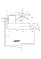
- FIG. 1 is a front view of a tube and microbubble generating medium according to one embodiment of the present invention
- the floating power generation unit 1 is installed in a natural water system such as the sea (sea), river (on the river), or lake (on the lake), and converts natural energy of the ocean such as wind power, wave power, tidal current, ocean current, and water current into electric energy. It is a device that generates electricity by
- the floating power generation unit 1 includes a power generation device 2, an oxygen separation device 3 that separates oxygen and nitrogen in the air using the power supplied by the power generation device 2, a float 4 that floats on the water, and an oxygen generator that discharges oxygen.
- a discharge pipe 5, a nitrogen discharge pipe 6 for discharging nitrogen, and pumps 7A and 7B for supplying water flow to the oxygen discharge pipe 5 and the nitrogen discharge pipe 6 are provided.
- the power generation device 2 is a device that generates electric power by rotationally driving the power generator 17 using natural energy.
- the generator 17 is rotationally driven by ocean natural energy such as wave power, tidal currents, and ocean currents. On the ocean or lake, the power of underwater waves or tides, or the wind power on water is used to rotate the turbine and drive the generator 17 .
- the wind turbine generator 2A includes a rotatable rotor 15 composed of a hub 13 having a rotating shaft (not shown) and a plurality of blades 14 attached to the hub 13. there is The rotor 15 is rotatably supported by the nacelle 16 via a rotation shaft (not shown), and transmits the rotational force of the rotor 15 to the generator 17 inside the nacelle 16 .
- the rotor 15 rotates when the blades 14 receive the wind, and the rotational force of the rotor 15 rotates the generator 17 to generate electric power.
- the power generation device 2 has a main power transmission cable 18A for transmitting power to various land power transmission facilities (not shown).
- the main power transmission cable 18A is branched and connected to an oxygen separation device power transmission cable 18B that transmits part of the power to the oxygen separator 3 and a pump power transmission cable 18C that transmits power to the pumps 7A and 7B.
- the oxygen separation device 3 is a device that separates and discharges oxygen in the air, and is a device that discharges residual air from which oxygen has been degassed as a gas that is mostly composed of nitrogen.
- the oxygen separator 3 include a pressure swing adsorption oxygen separator, a membrane separation oxygen separator, a cryogenic separation oxygen separator, and a vacuum pressure swing adsorption oxygen separator.
- a pressure fluctuation adsorption type oxygen separation device 3A which is one of the adsorption separation methods, will be described.
- the oxygen separator 3A separates air using an adsorbent that selectively adsorbs nitrogen.
- the adsorbent is composed of zeolites, for example. Oxygen can be efficiently obtained by removing nitrogen in the air under pressure by taking advantage of the fact that the equilibrium adsorption amounts of nitrogen and oxygen of the adsorbent differ greatly under pressure.
- the oxygen separator 3A is composed of a compressor 23 that compresses air, a dehumidifier 24 that dehumidifies the air pressure-fed from the compressor 23, and two adsorption towers 25A and 25B.
- the oxygen separator 3A generates oxygen by repeating the adsorption/desorption process.
- the compressor 23 takes in raw material air from the atmosphere.
- the compressed air is dehumidified by a dehumidifier 24 and sent to adsorption towers 25A and 25B.
- the paths to the two adsorption towers 25A and 25B are alternately switched every several tens of seconds by opening and closing the valves in the process described below.
- the air introduced into the first adsorption tower 25A is pressurized to the adsorption pressure.
- the second nitrogen discharge valve 28b of the second adsorption tower 25B is opened to reduce the pressure to atmospheric pressure and discharge the adsorbed nitrogen gas or the like to the nitrogen discharge pipe 6.
- the air introduced into the first adsorption tower 25A has nitrogen gas, carbon dioxide gas, moisture, etc. adsorbed by the adsorbent, and the oxygen gas is sent through the oxygen discharge pipe 5 from the first oxygen discharge valve 27c. (adsorption process).
- the adsorbent is regenerated with the oxygen gas from the first adsorption tower 25A that has passed through the orifices at the top of the two towers (desorption step).
- the second intake valve 28a, the first nitrogen discharge valve 27b, and the second oxygen discharge valve 28c are opened, the desorption process is performed in the first adsorption tower 25A, and the adsorption process is performed in the second adsorption tower 25B. I do. Then, when the adsorption step in the second adsorption tower 25B and the desorption step in the first adsorption tower 25A are finished, the second intake valve 28a, the first nitrogen discharge valve 27b, and the second oxygen discharge valve 28c are closed, The connecting valves 29 above and below both columns are opened to equalize the pressures in both columns. By repeating this, oxygen is supplied from the oxygen discharge pipe 5 and nitrogen is discharged from the nitrogen discharge pipe 6 .
- the float 4 is a foundation for installing the power generator 2 and the oxygen separator 3 on the water.
- the float 4 is a structure constructed by supporting a floating body block 4a with a plurality of support columns 4b, and has sufficient buoyancy to hold the power generation device 2 and the oxygen separation device 3 installed on the upper surface above the water. .
- Lake water, sea water, or the like can flow into the float 4, and the buoyancy of the float can be adjusted and balanced by flowing the lake water or sea water into the float.
- the float 4 is fixed to the bottom of the sea or the lake by strings and stakes (not shown), and recovers from tilted and rotated states by utilizing the moment of inertia.
- the oxygen discharge pipe 5 is a pipe for sending and discharging oxygen generated in the oxygen separator 3 into water.
- the discharge port 5a of the oxygen discharge pipe 5 is located below the water surface at a depth where aquatic organisms such as fish and shellfish are breeding.
- a fine bubble generating medium 33 is provided at the outlet 5a.
- the microbubble generating medium 33 is arranged in connection with the discharge port 5a, as shown in FIGS.
- the fine bubble generating medium 33 is arranged so as to be parallel to the direction in which the water pumped from the pump 7B flows (the black arrow direction in FIG. 2).
- the microbubble generating medium 33 is arranged parallel to the direction in which the water pumped from the pump 7B flows.
- the medium 33 may be arranged so that the downstream side is inclined downward with respect to the direction in which the water pumped from the pump 7B flows.
- the microbubble generating medium 33 is provided with an internal space 33a connected to the outlet 5a.
- the microbubble generating medium 33 is made of a carbon-based porous material, and as shown in FIG.
- the microbubble generating medium 33 is a conductor, and the bubbles generated from the microbubble generating medium 33 are negatively charged.
- free electrons are added to the ultra-fine bubbles when passing through the micro-bubble generating medium 33, which is a conductor, so that the ultra-fine bubbles are negatively charged. This negative charge can prevent the bubbles from repelling each other and coalescing into larger bubbles.
- a carbon-based porous material is a composite material containing only carbon or carbon and ceramic, and is an inorganic material.
- a film with a thickness of several nanometers is formed on the surface of the carbon-based porous material.
- the film is formed of an inorganic film containing silicon.
- the carbon-based porous material has oxidation resistance, does not rust, and does not deteriorate due to exposure even when placed in water for a long period of time.
- the surface is formed of an inorganic film containing silicon, it also has the property that it is difficult for aquatic organisms such as barnacles to adhere to it.
- Oxygen sent from the oxygen discharge pipe 5 to the internal space 33a moves to the surface of the microbubble generating medium 33 through fine holes 33A having a diameter of several ⁇ m to several tens of ⁇ m provided in the microbubble generating medium 33. .
- the oxygen that has moved to the surface of the microbubble generating medium 33 becomes ultrafine bubbles and is released into water by the force of water pumped from the pump 7B.
- the nitrogen discharge pipe 6 is a pipe that sends and discharges the nitrogen generated in the oxygen separation device 3 into the oxygen separation device 3 itself and water.
- the nitrogen discharge pipe 6 is branched, and one nitrogen discharge pipe 6 flows back into the oxygen separator 3 . This suppresses the oxidation of each part of the oxygen separation device 3 and prevents the generation of rust.
- another nitrogen discharge pipe 6 circulates inside the power generator 2 . As a result, it is possible to suppress oxidation of each component in the power generation device 2, particularly the electrodes and contacts, and prevent deterioration.
- the discharge port 6a of the nitrogen discharge pipe 6 is below the water surface and arranged so as to flow back into the float 4. That is, the nitrogen discharged from the nitrogen discharge pipe 6 is discharged into the seawater or lake water entering the float 4 .
- a microbubble generating medium 34 is provided at the discharge port 6a.
- the microbubble generating medium 34 is arranged in connection with the discharge port 6a, as shown in FIGS.
- the fine bubble generating medium 34 is arranged so as to be parallel to the direction in which the water pumped from the pump 7A flows (the black arrow direction in FIG. 2).
- the microbubble generating medium 34 is arranged parallel to the direction in which the water pumped from the pump 7A flows.
- the medium 34 may be arranged so that the downstream side is inclined downward with respect to the direction in which the water pumped from the pump 7A flows.
- the microbubble generating medium 34 is provided with an internal space 34a connected to the outlet 6a.
- the pump 7A also acts as a circulation pump that circulates the seawater or lake water inside the float 4.
- the seawater or lake water inside the float 4 is circulated and supplied, and the nitrogen concentration in the seawater or lake water inside the float 4 is increased by repeatedly supplying nitrogen as fine bubbles inside the float 4 .
- the microbubble generating medium 34 is made of a carbon-based porous material, and as shown in FIG. Further, the microbubble generating medium 34 is a conductor, and the bubbles generated from the microbubble generating medium 34 are negatively charged. In other words, free electrons are added to the ultra-fine bubbles when passing through the micro-bubble generating medium 34, which is a conductor, so that the ultra-fine bubbles are negatively charged. This negative charge can prevent the bubbles from repelling each other and coalescing into larger bubbles.
- a carbon-based porous material is a composite material containing only carbon or carbon and ceramic, and is an inorganic material. A film with a thickness of several nanometers is formed on the surface of the carbon-based porous material.
- the film is formed of an inorganic film containing silicon.
- Nitrogen sent from the nitrogen discharge pipe 6 to the internal space 34a moves to the surface of the microbubble generating medium 34 through fine holes 34A having a diameter of several ⁇ m to several tens of ⁇ m provided in the microbubble generating medium 34. .
- the oxygen that has moved to the surface of the microbubble generating medium 34 becomes ultrafine bubbles and is released into water by the force of water pressure-fed from the pump 7A.
- the oxygen separation device 3 is driven by supplying electric power generated by the power generation device 2 .
- the compressor 23 takes in raw air from the atmosphere.
- the compressed air is dehumidified by a dehumidifier 24 and sent to adsorption towers 25A and 25B.
- oxygen is produced and sent to the oxygen discharge pipe 5.
- the residual air from which oxygen has been degassed is discharged from the nitrogen discharge pipe 6 as a gas in which nitrogen accounts for the majority.
- the oxygen sent from the oxygen discharge pipe 5 is sent to the internal space 33a of the microbubble generating medium 33 and discharged as microbubbles through the micropores 33A.
- Oxygen generated on the surface of the microbubble generating medium 33 as microbubbles is separated from the surface and released into the water by the force of water pressure-fed from the pump 7B.
- By discharging oxygen in the form of microbubbles it is possible to increase the activity of aerobic organisms, promote the growth of plankton, and improve fishing grounds. As a result, abundant fishery resources can be secured without destroying the ecosystem of the fishing grounds near the floating power generation unit 1 .
- the floating power generation unit 1 In the water area where the floating power generation unit 1 was installed, the water flow was dammed up due to the construction of a structure in a place that was originally a fishing ground. As a result, the amount of oxygen supplied changes, and the growing environment for aquatic organisms sometimes deteriorates. However, in the floating power unit 1 described in the present invention, the water area near the floating power unit 1 can be supplied with sufficient oxygen. As a result, coexistence of power generation business and fishery can be achieved in one water area.
- the nitrogen sent from the nitrogen discharge pipe 6 is sent to the internal space 34a of the microbubble generating medium 34 and discharged as microbubbles from the micropores 34A.
- Nitrogen generated on the surface of the microbubble generating medium 34 as microbubbles is separated from the surface and released into the water by the force of water pressure-fed from the pump 7A.
- the nitrogen generated by the oxygen separator 3 does not have an oxidizing action, deterioration of the float 4 can be suppressed.
- the floating power generation unit 1 uses the oxygen and nitrogen in the air to improve the environment of the surrounding fishing grounds, prevent deterioration of the unit, and reduce the frequency of maintenance. It is possible.
- a dehumidifier 11 may be arranged inside the power generator 2 and the oxygen separator 3 to remove internal moisture. This can prevent deterioration due to moisture in the power generation device 2 and the oxygen separation device 3 that are placed in a humid environment on the water. Electric power is supplied to the dehumidifier 11 from the power generator 2 .
- the moisture absorbed by the dehumidifier 11 is stored in the dehumidifier in a liquid state, and after a certain amount is stored, it is discharged into the seawater or lake water in the float 4 .
- the floating power generation unit is arranged on the sea, the salinity of the seawater in the float 4 can be lowered, so that the deterioration of the float 4 due to the salinity can be prevented.
- the floating power generation unit 1 includes the power generation device 2, the oxygen separation device 3 that separates oxygen and nitrogen in the air using the power supplied by the power generation device 2, and the and a float 4, and a power generation device 2 and an oxygen separation device 3 are installed on the upper surface of the float 4, wherein the oxygen separated by the oxygen separation device 3 is supplied to water as fine bubbles. It is provided with a first microbubble generating medium 33 and a second microbubble generating medium 34 for supplying nitrogen separated by the oxygen separator 3 to water as microbubbles.
- the first microbubble generating medium 33 and the second microbubble generating medium 34 may be made of a carbon-based porous material. By configuring in this way, even if the first microbubble generating medium 33 and the second microbubble generating medium 34 are placed in water for a long period of time, they deteriorate because they are made of a carbon-based porous material. Maintenance is improved because there is no problem.
- the first microbubble generating medium 33 may be arranged at a deeper water depth than the second microbubble generating medium 34 .
- the present invention is a floating power generation unit that includes a structure such as a power generation device and is installed on a float that floats on the sea or on a lake. technology available.
Landscapes
- Chemical & Material Sciences (AREA)
- Engineering & Computer Science (AREA)
- Life Sciences & Earth Sciences (AREA)
- Chemical Kinetics & Catalysis (AREA)
- Environmental Sciences (AREA)
- Analytical Chemistry (AREA)
- Organic Chemistry (AREA)
- Mechanical Engineering (AREA)
- Combustion & Propulsion (AREA)
- Animal Husbandry (AREA)
- Marine Sciences & Fisheries (AREA)
- Biodiversity & Conservation Biology (AREA)
- General Chemical & Material Sciences (AREA)
- Oil, Petroleum & Natural Gas (AREA)
- Architecture (AREA)
- Civil Engineering (AREA)
- Ocean & Marine Engineering (AREA)
- Zoology (AREA)
- Structural Engineering (AREA)
- Inorganic Chemistry (AREA)
- General Engineering & Computer Science (AREA)
- Water Supply & Treatment (AREA)
- Environmental & Geological Engineering (AREA)
- Hydrology & Water Resources (AREA)
- Aeration Devices For Treatment Of Activated Polluted Sludge (AREA)
- Other Liquid Machine Or Engine Such As Wave Power Use (AREA)
- Wind Motors (AREA)
- Oxygen, Ozone, And Oxides In General (AREA)
- Laying Of Electric Cables Or Lines Outside (AREA)
- Farming Of Fish And Shellfish (AREA)
Abstract
水上発電を行いつつ酸素分を水中に微細気泡として散布することで好気性生物の活性を上げプランクトンの成長を促進し漁場の改良を行うことができる水上発電ユニットを提供する。発電装置(2)と、発電装置(2)によって供給される電力を用いて空気中の酸素と窒素を分離する酸素分離装置(3)と、水上に浮かべたフロート(4)と、を備え、フロート(4)の上面に発電装置(2)および酸素分離装置(3)を設置した水上発電ユニット(1)であって、酸素分離装置(3)により分離された酸素を、水中に微細気泡として供給する第一の微細気泡発生媒体(33)を備え、酸素分離装置(3)により分離された窒素を、水中に微細気泡として供給する第二の微細気泡発生媒体(34)を備える。
Description
本発明は、発電装置などの構造物を備え、海上または湖上に浮遊するフロートに設置される水上発電ユニットであって、フロート周辺の水中に酸素を供給する酸素供給装置を備えた水上発電ユニットの技術に関する。
近年、洋上または湖上などの水上の風力、波力、潮流・海流、水流等の自然エネルギーを電気エネルギーに変換して発電を行う、いわゆる再生可能自然エネルギーの開発が注目されている。
再生可能自然エネルギーが得られる水上発電ユニットの一例として、水上の風力を電気エネルギーに変換して発電することができる、いわゆる浮体式水上風力発電ユニットが挙げられ、その実用化が進められている。また、満潮時には堰を開放し、湾内に海水を導入し、干潮時に堰を閉鎖し、海水をタービンに導入することで潮汐流(潮汐による海水の移動)が持つ運動エネルギーを電力に変える水上潮力発電ユニットも挙げられ、その実用化がすすめられている。
水上発電ユニットの一例である、浮体式水上風力発電ユニットは、浮体設備に設けた発電用風車を、水上の風力によって回転させて電気エネルギーに変換した後、得られた電力を、水中ケーブルを通じて送電することができるように構成されている。
しかし、水上発電ユニットを配置した付近の水中においては、海流や水流が阻害されやすく、海水もしくは湖水が滞留して酸素が十分に供給されず、良好な漁場が形成されない場合があった。酸素の供給量が不足すると魚の餌となるプランクトンなどの発生量が少なくなるため、魚が集まり難く、また付近の魚の成長にも悪影響があった。
また、フロート付近の海流も滞留しやすく、フジツボなどの発生や微生物によるフロートの劣化が起こっていた。フロートの劣化によって、水上発電ユニットの維持コストが上昇してしまい、水上発電ユニットの利点である土地などを用いないことでの省コスト性が損なわれる場合があった。
そこで、本発明はかかる課題に鑑み、水上発電を行いつつ酸素分を水中に微細気泡として散布することで好気性生物の活性を上げプランクトンの成長を促進し漁場の改良を行うことができる水上発電ユニットを提供する。
本発明の解決しようとする課題は以上の如くであり、次にこの課題を解決するための手段を説明する。
即ち、本発明においては、発電装置と、前記発電装置によって供給される電力を用いて空気中の酸素と窒素を分離する酸素分離装置と、水上に浮かべたフロートと、を備え、前記フロートの上面に前記発電装置および酸素分離装置を設置した水上発電ユニットであって、
前記酸素分離装置により分離された酸素を、水中に微細気泡として供給する第一の微細気泡発生媒体を備え、
前記酸素分離装置により分離された窒素を、水中に微細気泡として供給する第二の微細気泡発生媒体を備えるものである。
前記酸素分離装置により分離された酸素を、水中に微細気泡として供給する第一の微細気泡発生媒体を備え、
前記酸素分離装置により分離された窒素を、水中に微細気泡として供給する第二の微細気泡発生媒体を備えるものである。
また、本発明においては、好ましくは、前記第一の微細気泡発生媒体および第二の微細気泡発生媒体は、炭素系の多孔質素材で形成されているものであってもよい。
また、本発明においては、好ましくは、前記第一の微細気泡発生媒体は、前記第二の微細気泡発生媒体よりも水深の深い位置に配置されているものであってもよい。
また、本発明においては、前記酸素分離装置により分離された窒素を、前記発電装置および前記酸素分離装置に供給し、前記発電装置および前記酸素分離装置内に充満させるものであってもよい。
本発明の効果として、以下に示すような効果を奏する。
本発明においては、水上発電を行いつつ、発電装置の電力を用いて空気中の酸素と窒素を分離する酸素分離装置によって生成した酸素分を水中に微細気泡として散布することができる。これにより、好気性生物の活性を上げプランクトンの成長を促進し漁場の改良を行うことができる。また、酸素分離装置によって生成した窒素分をフロート付近に流出させることで、フジツボなどの発生を抑えることができる。また、酸化作用を抑制してフロートの劣化を抑制することができ、メンテナンスコストを低減することができる。また、酸化防止のためにフロート内部へ微細気泡として添加することにより、水上発電ユニットの各装置の風化を防ぎ装置の寿命を長くすることができる。
また、本発明においては、炭素系の多孔質素材で形成されていることで微細気泡発生媒体を水中に長期間配置していても劣化することがないためメンテナンス性が向上する。
また、本発明においては、酸素分離装置によって生成した酸素分を水生生物が多い水深の深い水域に放出することが可能となる。また、酸素分離装置によって生成した窒素分をフロートの下面が配置されている水深の浅い水域に放出することができる。
また、本発明においては、酸素分離装置により分離された窒素を、前記発電装置および前記酸素分離装置内に充満させることで、発電装置および酸素分離装置内の各部品の酸化を防止し、錆の発生を抑えて劣化を防ぐことができる。
次に、発明の実施の形態を説明する。
まず、本発明の一実施形態にかかる水上発電ユニット1について図1を用いて説明する。
水上発電ユニット1は、海(海上)、河川(河上)もしくは湖(湖上)などの自然水系に設置され、風力、波力、潮流・海流・水流等の海洋の自然エネルギーを電気エネルギーに変換して発電を行う装置である。
まず、本発明の一実施形態にかかる水上発電ユニット1について図1を用いて説明する。
水上発電ユニット1は、海(海上)、河川(河上)もしくは湖(湖上)などの自然水系に設置され、風力、波力、潮流・海流・水流等の海洋の自然エネルギーを電気エネルギーに変換して発電を行う装置である。
水上発電ユニット1は、発電装置2と、発電装置2によって供給される電力を用いて空気中の酸素と窒素を分離する酸素分離装置3と、水上に浮かべたフロート4と、酸素を排出する酸素排出管5と、窒素を排出する窒素排出管6と、酸素排出管5および窒素排出管6に対して水流を供給するポンプ7A・7Bと、を備える。
発電装置2は、自然エネルギーによって発電機17を回転駆動させることにより電力を発生させる装置である。発電機17は、波力、潮流・海流等の海洋の自然エネルギーによって回転駆動される。洋上もしくは湖上においては、水中の波の力や潮汐の力、もしくは水上の風力を利用してタービンを回転させて発電機17を駆動する。
本実施形態における自然エネルギーを電気エネルギーに変換する発電装置の一例として、風力を電気エネルギーに変換して発電を行う風力発電装置2Aについて説明する。
図2に示すように、風力発電装置2Aは、回転軸(図では省略)を有するハブ13と、ハブ13に取付けられた複数のブレード14とで構成される、回転可能なロータ15を備えている。ロータ15は、図示しない回転軸を介してナセル16により回転可能に支持されており、ロータ15の回転力をナセル16内の発電機17に伝達する。風力発電装置2Aは、ブレード14が風を受けることでロータ15が回転し、ロータ15の回転力で発電機17を回転させて電力を発生させている。
図2に示すように、風力発電装置2Aは、回転軸(図では省略)を有するハブ13と、ハブ13に取付けられた複数のブレード14とで構成される、回転可能なロータ15を備えている。ロータ15は、図示しない回転軸を介してナセル16により回転可能に支持されており、ロータ15の回転力をナセル16内の発電機17に伝達する。風力発電装置2Aは、ブレード14が風を受けることでロータ15が回転し、ロータ15の回転力で発電機17を回転させて電力を発生させている。
発電装置2は、電力を図示せぬ陸上の各種送電設備へ送電するための主送電ケーブル18Aを有している。主送電ケーブル18Aは分岐しており、一部の電力を酸素分離装置3へ送電する酸素分離装置用送電ケーブル18B、ポンプ7A・7Bへ送電するポンプ用送電ケーブル18Cに連結されている。
酸素分離装置3は、空気中の酸素を分離させて排出する装置であり、酸素を脱気した残存空気を窒素が大部分を占める気体として排出する装置である。酸素分離装置3の例としては、圧力変動吸着型の酸素分離装置、膜分離型の酸素分離装置、深冷分離型の酸素分離装置、真空圧力スイング吸着型の酸素分離装置などが挙げられる。
本実施形態における酸素分離装置3の一例として、吸着分離方式の一つである圧力変動吸着型の酸素分離装置3Aについて説明する。
図3に示すように、酸素分離装置3Aは、窒素を選択的に吸着する吸着材を用いて空気を分離する。吸着剤は、例えばゼオライトで構成される。吸着剤の窒素と酸素の平衡吸着量が、加圧下で大きく異なる性質を利用し、空気中の窒素を加圧下で吸着除去することで、酸素を効率的に得ることができる。
酸素分離装置3Aは、空気を圧縮する圧縮機23と、圧縮機23より圧送される空気を除湿する除湿機24と、二つの吸着塔25A・25Bとで構成される。
酸素分離装置3Aは、吸着・脱着工程を繰り返す事によって酸素を生成するものである。
まず、圧縮機23において原料の空気を大気から取り込む。圧縮した空気は除湿機24にて水分を取り除き吸着塔25A・25Bに送られる。二つの吸着塔25A・25Bへの経路は、弁の開閉によって以下に示す工程で、数十秒単位で交互に切り替えられる。
まず、圧縮機23において原料の空気を大気から取り込む。圧縮した空気は除湿機24にて水分を取り除き吸着塔25A・25Bに送られる。二つの吸着塔25A・25Bへの経路は、弁の開閉によって以下に示す工程で、数十秒単位で交互に切り替えられる。
第一の吸入弁27aを開にすることで第一の吸着塔25Aに導入された空気は、吸着圧力まで昇圧される。一方、第二の吸着塔25Bの第二の窒素排出弁28bを開にし、大気圧まで減圧して吸着された窒素ガス等を窒素排出管6へ排出する。
第一の吸着塔25Aに導入された空気は、吸着剤に窒素ガス、炭酸ガス、水分等が吸着され、第一の酸素排出弁27cから酸素ガスが酸素排出管5を通って送気される(吸着工程)。一方、第二の吸着塔25Bにおいては、二つの塔上部のオリフィスを通ってきた第一の吸着塔25Aからの酸素ガスで吸着剤が再生される(脱着工程)。
第一の吸着塔25Aにおける吸着工程、第二の吸着塔25Bの脱着工程が終わると第一の吸入弁27a、第二の窒素排出弁28b、第一の酸素排出弁27cを閉めて、両塔の上下にある連結弁29を開けて両塔を均等な圧力にする。
次に、第二の吸入弁28a、第一の窒素排出弁27b、第二の酸素排出弁28cを開けて、第一の吸着塔25Aにおいて脱着工程を行い、第二の吸着塔25Bにおいて吸着工程を行う。そして、第二の吸着塔25Bにおける吸着工程、第一の吸着塔25Aの脱着工程が終わると第二の吸入弁28a、第一の窒素排出弁27b、第二の酸素排出弁28cを閉めて、両塔の上下にある連結弁29を開けて両塔を均等な圧力にする。
これを繰り返すことにより、酸素排出管5から酸素を供給し、窒素排出管6から窒素を排出する。
これを繰り返すことにより、酸素排出管5から酸素を供給し、窒素排出管6から窒素を排出する。
フロート4は、水上に発電装置2および酸素分離装置3を設置するための土台である。フロート4は、浮体ブロック4aを複数の支持柱4bによって支持することにより構成した構造物であり、上面に設置された発電装置2および酸素分離装置3を水上に保持するのに十分な浮力を有する。フロート4の内部には、湖水または海水等が流入可能であり、前記湖水または海水がフロート内に流入することで、フロートの浮力を調節しバランスをとることができる。
フロート4は、図示せぬ紐および杭によって、海底や湖底に固定されており、慣性モーメントを利用することで傾いた状態および回転した状態から復帰させる。
フロート4は、図示せぬ紐および杭によって、海底や湖底に固定されており、慣性モーメントを利用することで傾いた状態および回転した状態から復帰させる。
酸素排出管5は、酸素分離装置3において生成された酸素を水中に送り排出する管である。酸素排出管5の排出口5aは水面よりも下方であって、魚や貝などの水生生物が繁殖している深さに配置されている。排出口5aには、微細気泡発生媒体33が設けられている。
微細気泡発生媒体33は、図1及び図2に示すように、排出口5aに連結して配置されている。微細気泡発生媒体33は、ポンプ7Bから圧送される水が流れる方向(図2の黒塗り矢印方向)に対して平行となるように配置されている。なお、本実施形態においては、微細気泡発生媒体33は、ポンプ7Bから圧送される水が流れる方向に対して平行となるように配置されているが、これに限定するものではなく、微細気泡発生媒体33は、ポンプ7Bから圧送される水が流れる方向に対して下流側が下方へ傾くように配置されてもよい。微細気泡発生媒体33は、排出口5aと連結される内部空間33aが設けられている。
また、微細気泡発生媒体33は、炭素系の多孔質素材で構成されており、図3に示すように、直径数μm~数十μmの細かな孔33Aを多数有している。また、微細気泡発生媒体33は導電体であり、微細気泡発生媒体33から発生する気泡は負の電荷が帯電される。言い換えれば、導電体である微細気泡発生媒体33を通過する際に超微細気泡に自由電子が付加されることにより、負の電荷が帯電するものである。この負の電荷により、気泡同士が互いに反発し、合体して大きな気泡になることを防ぐことができる。
炭素系の多孔質素材とは、炭素のみ若しくは炭素及びセラミックを含む複合素材であり、無機質の素材である。また、炭素系の多孔質素材の表面には、厚さ数nmの膜が形成されている。前記膜はケイ素を含む無機質の膜で形成されている。炭素系の多孔質素材は、耐酸化性を有しており、錆が発生せず長期間水中に配置した場合であっても参加による劣化が発生しない。また、表面がケイ素を含む無機質の膜で形成されており、フジツボ等の水生生物が付着しにくい性質も有する。
酸素排出管5から内部空間33aへ送られた酸素は、微細気泡発生媒体33に設けられた直径数μm~数十μmの細かな孔33Aを通って、微細気泡発生媒体33の表面へ移動する。微細気泡発生媒体33の表面に移動した酸素は超微細気泡となり、ポンプ7Bから圧送される水の力によって水中へ放出される。
窒素排出管6は、酸素分離装置3において生成された窒素を、酸素分離装置3自体および水中に送り排出する管である。窒素排出管6は分岐しており、一つの窒素排出管6は、酸素分離装置3内部に還流する。これにより、酸素分離装置3の各部品の酸化を抑制し、錆の発生を防止する。また、別の窒素排出管6は、発電装置2の内部に還流する。これにより、発電装置2内の各部品、特に電極や接点などの酸化を抑制し、劣化を防ぐことができる。
また、窒素排出管6の排出口6aは水面よりも下方であって、フロート4の内部に還流するように配置されている。すなわち、窒素排出管6から排出された窒素が、フロート4の内部に入る海水または湖水に排出されるように構成されている。これにより、窒素をふくむ海水または湖水がフロート4の浮体ブロック4aや支持柱4bなどの各部品に接触しやすくなり、各部品の酸化を抑制し、錆の発生を防止する。排出口6aには、微細気泡発生媒体34が設けられている。
微細気泡発生媒体34は、図1及び図2に示すように、排出口6aに連結して配置されている。微細気泡発生媒体34は、ポンプ7Aから圧送される水が流れる方向(図2の黒塗り矢印方向)に対して平行となるように配置されている。なお、本実施形態においては、微細気泡発生媒体34は、ポンプ7Aから圧送される水が流れる方向に対して平行となるように配置されているが、これに限定するものではなく、微細気泡発生媒体34は、ポンプ7Aから圧送される水が流れる方向に対して下流側が下方へ傾くように配置されてもよい。微細気泡発生媒体34は、排出口6aと連結される内部空間34aが設けられている。
ポンプ7Aは、フロート4内部の海水または湖水を循環させる循環ポンプとしても作用する。フロート4内部の海水または湖水は循環して供給され、フロート4の内部において、繰り返し窒素を微細気泡として供給されることにより、フロート4内部の海水または湖水内の窒素濃度が上がる。
また、微細気泡発生媒体34は、炭素系の多孔質素材で構成されており、図3に示すように、直径数μm~数十μmの細かな孔34Aを多数有している。また、微細気泡発生媒体34は導電体であり、微細気泡発生媒体34から発生する気泡は負の電荷が帯電される。言い換えれば、導電体である微細気泡発生媒体34を通過する際に超微細気泡に自由電子が付加されることにより、負の電荷が帯電するものである。この負の電荷により、気泡同士が互いに反発し、合体して大きな気泡になることを防ぐことができる。
炭素系の多孔質素材とは、炭素のみ若しくは炭素及びセラミックを含む複合素材であり、無機質の素材である。また、炭素系の多孔質素材の表面には、厚さ数nmの膜が形成されている。前記膜はケイ素を含む無機質の膜で形成されている。
窒素排出管6から内部空間34aへ送られた窒素は、微細気泡発生媒体34に設けられた直径数μm~数十μmの細かな孔34Aを通って、微細気泡発生媒体34の表面へ移動する。微細気泡発生媒体34の表面に移動した酸素は超微細気泡となり、ポンプ7Aから圧送される水の力によって水中へ放出される。
炭素系の多孔質素材とは、炭素のみ若しくは炭素及びセラミックを含む複合素材であり、無機質の素材である。また、炭素系の多孔質素材の表面には、厚さ数nmの膜が形成されている。前記膜はケイ素を含む無機質の膜で形成されている。
窒素排出管6から内部空間34aへ送られた窒素は、微細気泡発生媒体34に設けられた直径数μm~数十μmの細かな孔34Aを通って、微細気泡発生媒体34の表面へ移動する。微細気泡発生媒体34の表面に移動した酸素は超微細気泡となり、ポンプ7Aから圧送される水の力によって水中へ放出される。
次に水上発電ユニット1において、酸素および窒素を微細気泡として供給する工程を説明する。
発電装置2において、発電された電力を供給することにより、酸素分離装置3が駆動する。酸素分離装置3では、圧縮機23において原料の空気を大気から取り込む。圧縮した空気は除湿機24にて水分を取り除き吸着塔25A・25Bに送られる。二つの吸着塔25A・25Bにおいて吸着・脱着工程を繰り返す事によって酸素が生成され、酸素排出管5へと送られる。また、酸素を脱気した残存空気を窒素が大部分を占める気体として窒素排出管6から排出する。
発電装置2において、発電された電力を供給することにより、酸素分離装置3が駆動する。酸素分離装置3では、圧縮機23において原料の空気を大気から取り込む。圧縮した空気は除湿機24にて水分を取り除き吸着塔25A・25Bに送られる。二つの吸着塔25A・25Bにおいて吸着・脱着工程を繰り返す事によって酸素が生成され、酸素排出管5へと送られる。また、酸素を脱気した残存空気を窒素が大部分を占める気体として窒素排出管6から排出する。
酸素排出管5から送られた酸素は、微細気泡発生媒体33の内部空間33aへ送られ、微細な孔33Aから微細気泡として排出される。微細気泡として微細気泡発生媒体33の表面に発生した酸素は、ポンプ7Bから圧送される水の力によって表面から離間して水中へ放出される。酸素が微細気泡として排出されることにより、好気性生物の活性を上げプランクトンの成長を促進し漁場の改良を行うことができる。これにより、水上発電ユニット1付近の漁場の生態系が崩されることなく豊富な水産資源を確保することができる。水上発電ユニット1を設置した水域においては、本来漁場であった場所に構造物ができるため水流がせき止められていた。このため酸素の供給量が変化し、水生生物の生育環境が悪化する場合があった。しかし、本願発明に記載された水上発電ユニット1においては、水上発電ユニット1付近の水域に十分な酸素を供給することができる。これにより、一つの水域において発電事業および漁業の共存を図ることができる。
また、窒素排出管6から送られた窒素は、微細気泡発生媒体34の内部空間34aへ送られ、微細な孔34Aから微細気泡として排出される。微細気泡として微細気泡発生媒体34の表面に発生した窒素は、ポンプ7Aから圧送される水の力によって表面から離間して水中へ放出される。窒素が微細気泡として排出されることにより、付近のフロート4の酸化が防止されることとなり錆の発生を抑制することができる。また、酸素分離装置3によって生成した窒素分は酸化作用がないためフロート4の劣化を抑制することができる。
このように、水上発電ユニット1は、空気中の酸素および窒素を用いて、周辺の漁場の環境を改良し、また、ユニットの劣化を防止しメンテナンスの回数を低減することができるという効果を奏することができるのである。
このように、水上発電ユニット1は、空気中の酸素および窒素を用いて、周辺の漁場の環境を改良し、また、ユニットの劣化を防止しメンテナンスの回数を低減することができるという効果を奏することができるのである。
また、図1に示すように、発電装置2および酸素分離装置3の内部には、内部の湿気を除去するための除湿機11が配置されていてもよい。これにより、水上の湿気の多い環境に配置された発電装置2および酸素分離装置3における水分による劣化を防ぐことができる。除湿機11には、発電装置2から電力が供給される。
除湿機11によって吸湿された水分は、除湿機内に液体状態で貯蔵され、一定量貯蔵された後、フロート4内の海水または湖水に排出される。水上発電ユニットを海上に配置した場合、フロート4内の海水の塩分濃度を下げることができるため、フロート4の塩分による劣化を防ぐことができる。
以上のように、本実施形態にかかる水上発電ユニット1は、発電装置2と、発電装置2によって供給される電力を用いて空気中の酸素と窒素を分離する酸素分離装置3と、水上に浮かべたフロート4と、を備え、フロート4の上面に発電装置2および酸素分離装置3を設置した水上発電ユニット1であって、酸素分離装置3により分離された酸素を、水中に微細気泡として供給する第一の微細気泡発生媒体33を備え、酸素分離装置3により分離された窒素を、水中に微細気泡として供給する第二の微細気泡発生媒体34を備えるものである。
このように構成することにより、水上発電を行いつつ、発電装置2の電力を用いて空気中の酸素と窒素を分離する酸素分離装置3によって生成した酸素分を水中に微細気泡として散布することができる。これにより、好気性生物の活性を上げプランクトンの成長を促進し漁場の改良を行うことができる。また、酸素分離装置3によって生成した窒素分をフロート4付近に流出させることで、フジツボなどの発生を抑えることができる。また、酸化作用を抑制してフロート4の劣化を抑制することができ、メンテナンスコストを低減することができる。また、微細気泡発生媒体34を用いた発生方法においては、微細気泡を発生させる動力が小さいので発電した電気を無駄なく使うことができる。
このように構成することにより、水上発電を行いつつ、発電装置2の電力を用いて空気中の酸素と窒素を分離する酸素分離装置3によって生成した酸素分を水中に微細気泡として散布することができる。これにより、好気性生物の活性を上げプランクトンの成長を促進し漁場の改良を行うことができる。また、酸素分離装置3によって生成した窒素分をフロート4付近に流出させることで、フジツボなどの発生を抑えることができる。また、酸化作用を抑制してフロート4の劣化を抑制することができ、メンテナンスコストを低減することができる。また、微細気泡発生媒体34を用いた発生方法においては、微細気泡を発生させる動力が小さいので発電した電気を無駄なく使うことができる。
また、第一の微細気泡発生媒体33および第二の微細気泡発生媒体34は、炭素系の多孔質素材で形成されているものであってもよい。
このように構成することにより、炭素系の多孔質素材で形成されていることで第一の微細気泡発生媒体33および第二の微細気泡発生媒体34を水中に長期間配置していても劣化することがないためメンテナンス性が向上する。
このように構成することにより、炭素系の多孔質素材で形成されていることで第一の微細気泡発生媒体33および第二の微細気泡発生媒体34を水中に長期間配置していても劣化することがないためメンテナンス性が向上する。
また、第一の微細気泡発生媒体33は、第二の微細気泡発生媒体34よりも水深の深い位置に配置されているものであってもよい。
このように構成することにより、酸素分離装置3によって生成した酸素分を水生生物が多い水深の深い水域に放出することが可能となる。また、酸素分離装置3によって生成した窒素分をフロートの下面が配置されている水深の浅い水域に放出することが可能となる。
このように構成することにより、酸素分離装置3によって生成した酸素分を水生生物が多い水深の深い水域に放出することが可能となる。また、酸素分離装置3によって生成した窒素分をフロートの下面が配置されている水深の浅い水域に放出することが可能となる。
本発明は、発電装置などの構造物を備え、海上または湖上に浮遊するフロートに設置される水上発電ユニットであって、フロート周辺の水中に酸素を供給する酸素供給装置を備えた水上発電ユニットの技術に利用可能である。
1 水上発電ユニット
2 発電装置
2A 風力発電装置2A
3 酸素分離装置
3A 酸素分離装置
4 フロート
4a 浮体ブロック
4b 支持柱
5 酸素排出管
5a 排出口
6 窒素排出管
6a 排出口
6A 孔
7A・7B ポンプ
11 除湿機
13 ハブ
14 ブレード
15 ロータ
16 ナセル
17 発電機
18A 主送電ケーブル
18B 酸素分離装置用送電ケーブル
18C ポンプ用送電ケーブル
23 圧縮機
24 除湿機
25A 第一の吸着塔
25B 第二の吸着塔
27a 第一の吸入弁
27b 第一の窒素排出弁
27c 第一の酸素排出弁
28a 第二の吸入弁
28b 第二の窒素排出弁
28c 第二の酸素排出弁
29 連結弁
33 第一の微細気泡発生媒体
33a 内部空間
33A 孔
34 第二の微細気泡発生媒体
34a 内部空間
34A 孔
2 発電装置
2A 風力発電装置2A
3 酸素分離装置
3A 酸素分離装置
4 フロート
4a 浮体ブロック
4b 支持柱
5 酸素排出管
5a 排出口
6 窒素排出管
6a 排出口
6A 孔
7A・7B ポンプ
11 除湿機
13 ハブ
14 ブレード
15 ロータ
16 ナセル
17 発電機
18A 主送電ケーブル
18B 酸素分離装置用送電ケーブル
18C ポンプ用送電ケーブル
23 圧縮機
24 除湿機
25A 第一の吸着塔
25B 第二の吸着塔
27a 第一の吸入弁
27b 第一の窒素排出弁
27c 第一の酸素排出弁
28a 第二の吸入弁
28b 第二の窒素排出弁
28c 第二の酸素排出弁
29 連結弁
33 第一の微細気泡発生媒体
33a 内部空間
33A 孔
34 第二の微細気泡発生媒体
34a 内部空間
34A 孔
Claims (4)
- 発電装置と、前記発電装置によって供給される電力を用いて空気中の酸素と窒素を分離する酸素分離装置と、水上に浮かべたフロートと、を備え、前記フロートの上面に前記発電装置および酸素分離装置を設置した水上発電ユニットであって、
前記酸素分離装置により分離された酸素を、水中に微細気泡として供給する第一の微細気泡発生媒体を備え、
前記酸素分離装置により分離された窒素を、水中に微細気泡として供給する第二の微細気泡発生媒体を備える、
ことを特徴とする水上発電ユニット。 - 前記第一の微細気泡発生媒体および第二の微細気泡発生媒体は、炭素系の多孔質素材で形成されている、
ことを特徴とする請求項1に記載の水上発電ユニット。 - 前記第一の微細気泡発生媒体は、前記第二の微細気泡発生媒体よりも水深の深い位置に配置されている、
ことを特徴とする請求項1または2に記載の水上発電ユニット。 - 前記酸素分離装置により分離された窒素を、前記発電装置および前記酸素分離装置に供給し、前記発電装置および前記酸素分離装置内に充満させる
ことを特徴とする請求項1から3のいずれか一項に記載の水上発電ユニット。
Priority Applications (2)
| Application Number | Priority Date | Filing Date | Title |
|---|---|---|---|
| EP22852896.4A EP4382407A4 (en) | 2021-08-05 | 2022-07-26 | FLOATING POWER GENERATION UNIT |
| US18/291,302 US20250382035A1 (en) | 2021-08-05 | 2022-07-26 | Floating power generation unit |
Applications Claiming Priority (2)
| Application Number | Priority Date | Filing Date | Title |
|---|---|---|---|
| JP2021-129172 | 2021-08-05 | ||
| JP2021129172A JP7829290B2 (ja) | 2021-08-05 | 2021-08-05 | 水上発電ユニット |
Publications (1)
| Publication Number | Publication Date |
|---|---|
| WO2023013473A1 true WO2023013473A1 (ja) | 2023-02-09 |
Family
ID=85154491
Family Applications (1)
| Application Number | Title | Priority Date | Filing Date |
|---|---|---|---|
| PCT/JP2022/028755 Ceased WO2023013473A1 (ja) | 2021-08-05 | 2022-07-26 | 水上発電ユニット |
Country Status (4)
| Country | Link |
|---|---|
| US (1) | US20250382035A1 (ja) |
| EP (1) | EP4382407A4 (ja) |
| JP (1) | JP7829290B2 (ja) |
| WO (1) | WO2023013473A1 (ja) |
Citations (7)
| Publication number | Priority date | Publication date | Assignee | Title |
|---|---|---|---|---|
| CN205794518U (zh) * | 2016-04-21 | 2016-12-14 | 佛山市百特利农业生态科技有限公司 | 一种作用于耗氧的水生动物密度养殖的生态平衡系统 |
| JP2017112969A (ja) * | 2015-12-25 | 2017-06-29 | 聡 安斎 | 活魚麻酔装置 |
| JP6242465B1 (ja) * | 2016-11-18 | 2017-12-06 | 株式会社御池鐵工所 | 水質改良装置 |
| WO2017217402A1 (ja) * | 2016-06-15 | 2017-12-21 | 聡 安斎 | 養殖用または排水処理用超微細気泡発生装置 |
| JP2019010608A (ja) * | 2017-06-29 | 2019-01-24 | 聡 安斎 | 超微細気泡発生装置 |
| JP2021030893A (ja) | 2019-08-23 | 2021-03-01 | 古河電気工業株式会社 | 浮体式海洋構造物ならびに浮体式洋上風力発電システムおよび浮体式石油・ガス生産貯蔵積出システム |
| WO2021153130A1 (ja) * | 2020-01-28 | 2021-08-05 | 聡 安斎 | 水質浄化装置 |
Family Cites Families (2)
| Publication number | Priority date | Publication date | Assignee | Title |
|---|---|---|---|---|
| JP6047518B2 (ja) | 2014-04-06 | 2016-12-21 | 国男 福田 | 水質改善方法及びその装置 |
| CN108782370B (zh) * | 2018-08-15 | 2024-04-19 | 山东省科学院生物研究所 | 一种评价待测物对机体运动耐力影响的方法及其专用设备 |
-
2021
- 2021-08-05 JP JP2021129172A patent/JP7829290B2/ja active Active
-
2022
- 2022-07-26 WO PCT/JP2022/028755 patent/WO2023013473A1/ja not_active Ceased
- 2022-07-26 EP EP22852896.4A patent/EP4382407A4/en active Pending
- 2022-07-26 US US18/291,302 patent/US20250382035A1/en active Pending
Patent Citations (7)
| Publication number | Priority date | Publication date | Assignee | Title |
|---|---|---|---|---|
| JP2017112969A (ja) * | 2015-12-25 | 2017-06-29 | 聡 安斎 | 活魚麻酔装置 |
| CN205794518U (zh) * | 2016-04-21 | 2016-12-14 | 佛山市百特利农业生态科技有限公司 | 一种作用于耗氧的水生动物密度养殖的生态平衡系统 |
| WO2017217402A1 (ja) * | 2016-06-15 | 2017-12-21 | 聡 安斎 | 養殖用または排水処理用超微細気泡発生装置 |
| JP6242465B1 (ja) * | 2016-11-18 | 2017-12-06 | 株式会社御池鐵工所 | 水質改良装置 |
| JP2019010608A (ja) * | 2017-06-29 | 2019-01-24 | 聡 安斎 | 超微細気泡発生装置 |
| JP2021030893A (ja) | 2019-08-23 | 2021-03-01 | 古河電気工業株式会社 | 浮体式海洋構造物ならびに浮体式洋上風力発電システムおよび浮体式石油・ガス生産貯蔵積出システム |
| WO2021153130A1 (ja) * | 2020-01-28 | 2021-08-05 | 聡 安斎 | 水質浄化装置 |
Non-Patent Citations (1)
| Title |
|---|
| See also references of EP4382407A4 |
Also Published As
| Publication number | Publication date |
|---|---|
| JP7829290B2 (ja) | 2026-03-13 |
| EP4382407A4 (en) | 2025-08-20 |
| US20250382035A1 (en) | 2025-12-18 |
| JP2023023558A (ja) | 2023-02-16 |
| EP4382407A1 (en) | 2024-06-12 |
Similar Documents
| Publication | Publication Date | Title |
|---|---|---|
| KR101105063B1 (ko) | 수류 동력 발생 시스템 | |
| CN101248268B (zh) | 发电装置及发电方法 | |
| CN101970854B (zh) | 从水流中获取能量的设备 | |
| JP2012509429A (ja) | 海洋波力発電装置 | |
| CN105432548A (zh) | 一种潜水式涡轮增氧机 | |
| KR101794207B1 (ko) | 태양광 발전을 이용한 수질 정화 장치 | |
| CN101960138A (zh) | 用于产生能量的方法和装置 | |
| JP2004068638A (ja) | 海流発電装置 | |
| JP2016175058A (ja) | 自然エネルギーを利用した曝気装置及び曝気方法 | |
| CN2828356Y (zh) | 潜浮式风浪发电船 | |
| KR20090079119A (ko) | 부유식 수질정화장치 | |
| JP7117787B2 (ja) | 酸素供給装置 | |
| KR20100135010A (ko) | 수중부양회전체를 이용한 수중 발전장치 | |
| WO2023013473A1 (ja) | 水上発電ユニット | |
| ES2315481T3 (es) | Evacuacion de fluidos residuales. | |
| JP2019010608A (ja) | 超微細気泡発生装置 | |
| CN101749167A (zh) | 正倒虹吸式海浪发电方法及发电机 | |
| GB2448393A (en) | Paddle wheel power generator supported between floats | |
| GB2400413A (en) | Current or tide power generator with endless belt supported on a floating hull | |
| JP2011196361A (ja) | 水上発電装置 | |
| AU2007231797A1 (en) | Desalination and power generation plant | |
| JP2009174510A (ja) | 海上で旋回する環状浮体構造体 | |
| JP2005273464A (ja) | 海底潮流水車を用いた発電設備及び深層水汲み上げ設備 | |
| US20140138955A1 (en) | Vertical axis mooring rotor | |
| KR20100118549A (ko) | 풍력, 조류, 해류 및 파력을 이용한 발전시스템 |
Legal Events
| Date | Code | Title | Description |
|---|---|---|---|
| 121 | Ep: the epo has been informed by wipo that ep was designated in this application |
Ref document number: 22852896 Country of ref document: EP Kind code of ref document: A1 |
|
| NENP | Non-entry into the national phase |
Ref country code: DE |
|
| ENP | Entry into the national phase |
Ref document number: 2022852896 Country of ref document: EP Effective date: 20240305 |