WO2023013566A1 - 車両制御装置 - Google Patents
車両制御装置 Download PDFInfo
- Publication number
- WO2023013566A1 WO2023013566A1 PCT/JP2022/029415 JP2022029415W WO2023013566A1 WO 2023013566 A1 WO2023013566 A1 WO 2023013566A1 JP 2022029415 W JP2022029415 W JP 2022029415W WO 2023013566 A1 WO2023013566 A1 WO 2023013566A1
- Authority
- WO
- WIPO (PCT)
- Prior art keywords
- vehicle
- speed
- estimated
- control device
- vehicle speed
- Prior art date
- Legal status (The legal status is an assumption and is not a legal conclusion. Google has not performed a legal analysis and makes no representation as to the accuracy of the status listed.)
- Ceased
Links
Images


Classifications
-
- B—PERFORMING OPERATIONS; TRANSPORTING
- B60—VEHICLES IN GENERAL
- B60W—CONJOINT CONTROL OF VEHICLE SUB-UNITS OF DIFFERENT TYPE OR DIFFERENT FUNCTION; CONTROL SYSTEMS SPECIALLY ADAPTED FOR HYBRID VEHICLES; ROAD VEHICLE DRIVE CONTROL SYSTEMS FOR PURPOSES NOT RELATED TO THE CONTROL OF A PARTICULAR SUB-UNIT
- B60W10/00—Conjoint control of vehicle sub-units of different type or different function
- B60W10/04—Conjoint control of vehicle sub-units of different type or different function including control of propulsion units
- B60W10/08—Conjoint control of vehicle sub-units of different type or different function including control of propulsion units including control of electric propulsion units, e.g. motors or generators
-
- B—PERFORMING OPERATIONS; TRANSPORTING
- B60—VEHICLES IN GENERAL
- B60L—PROPULSION OF ELECTRICALLY-PROPELLED VEHICLES; SUPPLYING ELECTRIC POWER FOR AUXILIARY EQUIPMENT OF ELECTRICALLY-PROPELLED VEHICLES; ELECTRODYNAMIC BRAKE SYSTEMS FOR VEHICLES IN GENERAL; MAGNETIC SUSPENSION OR LEVITATION FOR VEHICLES; MONITORING OPERATING VARIABLES OF ELECTRICALLY-PROPELLED VEHICLES; ELECTRIC SAFETY DEVICES FOR ELECTRICALLY-PROPELLED VEHICLES
- B60L15/00—Methods, circuits, or devices for controlling the traction-motor speed of electrically-propelled vehicles
- B60L15/20—Methods, circuits, or devices for controlling the traction-motor speed of electrically-propelled vehicles for control of the vehicle or its driving motor to achieve a desired performance, e.g. speed, torque, programmed variation of speed
-
- B—PERFORMING OPERATIONS; TRANSPORTING
- B60—VEHICLES IN GENERAL
- B60L—PROPULSION OF ELECTRICALLY-PROPELLED VEHICLES; SUPPLYING ELECTRIC POWER FOR AUXILIARY EQUIPMENT OF ELECTRICALLY-PROPELLED VEHICLES; ELECTRODYNAMIC BRAKE SYSTEMS FOR VEHICLES IN GENERAL; MAGNETIC SUSPENSION OR LEVITATION FOR VEHICLES; MONITORING OPERATING VARIABLES OF ELECTRICALLY-PROPELLED VEHICLES; ELECTRIC SAFETY DEVICES FOR ELECTRICALLY-PROPELLED VEHICLES
- B60L3/00—Electric devices on electrically-propelled vehicles for safety purposes; Monitoring operating variables, e.g. speed, deceleration or energy consumption
- B60L3/0023—Detecting, eliminating, remedying or compensating for drive train abnormalities, e.g. failures within the drive train
- B60L3/0038—Detecting, eliminating, remedying or compensating for drive train abnormalities, e.g. failures within the drive train relating to sensors
-
- G—PHYSICS
- G01—MEASURING; TESTING
- G01P—MEASURING LINEAR OR ANGULAR SPEED, ACCELERATION, DECELERATION, OR SHOCK; INDICATING PRESENCE, ABSENCE, OR DIRECTION, OF MOVEMENT
- G01P3/00—Measuring linear or angular speed; Measuring differences of linear or angular speeds
- G01P3/42—Devices characterised by the use of electric or magnetic means
- G01P3/56—Devices characterised by the use of electric or magnetic means for comparing two speeds
-
- B—PERFORMING OPERATIONS; TRANSPORTING
- B60—VEHICLES IN GENERAL
- B60L—PROPULSION OF ELECTRICALLY-PROPELLED VEHICLES; SUPPLYING ELECTRIC POWER FOR AUXILIARY EQUIPMENT OF ELECTRICALLY-PROPELLED VEHICLES; ELECTRODYNAMIC BRAKE SYSTEMS FOR VEHICLES IN GENERAL; MAGNETIC SUSPENSION OR LEVITATION FOR VEHICLES; MONITORING OPERATING VARIABLES OF ELECTRICALLY-PROPELLED VEHICLES; ELECTRIC SAFETY DEVICES FOR ELECTRICALLY-PROPELLED VEHICLES
- B60L2220/00—Electrical machine types; Structures or applications thereof
- B60L2220/40—Electrical machine applications
- B60L2220/42—Electrical machine applications with use of more than one motor
-
- B—PERFORMING OPERATIONS; TRANSPORTING
- B60—VEHICLES IN GENERAL
- B60L—PROPULSION OF ELECTRICALLY-PROPELLED VEHICLES; SUPPLYING ELECTRIC POWER FOR AUXILIARY EQUIPMENT OF ELECTRICALLY-PROPELLED VEHICLES; ELECTRODYNAMIC BRAKE SYSTEMS FOR VEHICLES IN GENERAL; MAGNETIC SUSPENSION OR LEVITATION FOR VEHICLES; MONITORING OPERATING VARIABLES OF ELECTRICALLY-PROPELLED VEHICLES; ELECTRIC SAFETY DEVICES FOR ELECTRICALLY-PROPELLED VEHICLES
- B60L2240/00—Control parameters of input or output; Target parameters
- B60L2240/10—Vehicle control parameters
- B60L2240/12—Speed
-
- B—PERFORMING OPERATIONS; TRANSPORTING
- B60—VEHICLES IN GENERAL
- B60L—PROPULSION OF ELECTRICALLY-PROPELLED VEHICLES; SUPPLYING ELECTRIC POWER FOR AUXILIARY EQUIPMENT OF ELECTRICALLY-PROPELLED VEHICLES; ELECTRODYNAMIC BRAKE SYSTEMS FOR VEHICLES IN GENERAL; MAGNETIC SUSPENSION OR LEVITATION FOR VEHICLES; MONITORING OPERATING VARIABLES OF ELECTRICALLY-PROPELLED VEHICLES; ELECTRIC SAFETY DEVICES FOR ELECTRICALLY-PROPELLED VEHICLES
- B60L2240/00—Control parameters of input or output; Target parameters
- B60L2240/40—Drive Train control parameters
- B60L2240/42—Drive Train control parameters related to electric machines
- B60L2240/421—Speed
-
- B—PERFORMING OPERATIONS; TRANSPORTING
- B60—VEHICLES IN GENERAL
- B60L—PROPULSION OF ELECTRICALLY-PROPELLED VEHICLES; SUPPLYING ELECTRIC POWER FOR AUXILIARY EQUIPMENT OF ELECTRICALLY-PROPELLED VEHICLES; ELECTRODYNAMIC BRAKE SYSTEMS FOR VEHICLES IN GENERAL; MAGNETIC SUSPENSION OR LEVITATION FOR VEHICLES; MONITORING OPERATING VARIABLES OF ELECTRICALLY-PROPELLED VEHICLES; ELECTRIC SAFETY DEVICES FOR ELECTRICALLY-PROPELLED VEHICLES
- B60L2240/00—Control parameters of input or output; Target parameters
- B60L2240/40—Drive Train control parameters
- B60L2240/46—Drive Train control parameters related to wheels
- B60L2240/461—Speed
-
- B—PERFORMING OPERATIONS; TRANSPORTING
- B60—VEHICLES IN GENERAL
- B60L—PROPULSION OF ELECTRICALLY-PROPELLED VEHICLES; SUPPLYING ELECTRIC POWER FOR AUXILIARY EQUIPMENT OF ELECTRICALLY-PROPELLED VEHICLES; ELECTRODYNAMIC BRAKE SYSTEMS FOR VEHICLES IN GENERAL; MAGNETIC SUSPENSION OR LEVITATION FOR VEHICLES; MONITORING OPERATING VARIABLES OF ELECTRICALLY-PROPELLED VEHICLES; ELECTRIC SAFETY DEVICES FOR ELECTRICALLY-PROPELLED VEHICLES
- B60L2240/00—Control parameters of input or output; Target parameters
- B60L2240/40—Drive Train control parameters
- B60L2240/46—Drive Train control parameters related to wheels
- B60L2240/465—Slip
-
- B—PERFORMING OPERATIONS; TRANSPORTING
- B60—VEHICLES IN GENERAL
- B60L—PROPULSION OF ELECTRICALLY-PROPELLED VEHICLES; SUPPLYING ELECTRIC POWER FOR AUXILIARY EQUIPMENT OF ELECTRICALLY-PROPELLED VEHICLES; ELECTRODYNAMIC BRAKE SYSTEMS FOR VEHICLES IN GENERAL; MAGNETIC SUSPENSION OR LEVITATION FOR VEHICLES; MONITORING OPERATING VARIABLES OF ELECTRICALLY-PROPELLED VEHICLES; ELECTRIC SAFETY DEVICES FOR ELECTRICALLY-PROPELLED VEHICLES
- B60L2260/00—Operating Modes
- B60L2260/40—Control modes
- B60L2260/44—Control modes by parameter estimation
-
- B—PERFORMING OPERATIONS; TRANSPORTING
- B60—VEHICLES IN GENERAL
- B60W—CONJOINT CONTROL OF VEHICLE SUB-UNITS OF DIFFERENT TYPE OR DIFFERENT FUNCTION; CONTROL SYSTEMS SPECIALLY ADAPTED FOR HYBRID VEHICLES; ROAD VEHICLE DRIVE CONTROL SYSTEMS FOR PURPOSES NOT RELATED TO THE CONTROL OF A PARTICULAR SUB-UNIT
- B60W2510/00—Input parameters relating to a particular sub-units
- B60W2510/08—Electric propulsion units
- B60W2510/083—Torque
-
- B—PERFORMING OPERATIONS; TRANSPORTING
- B60—VEHICLES IN GENERAL
- B60W—CONJOINT CONTROL OF VEHICLE SUB-UNITS OF DIFFERENT TYPE OR DIFFERENT FUNCTION; CONTROL SYSTEMS SPECIALLY ADAPTED FOR HYBRID VEHICLES; ROAD VEHICLE DRIVE CONTROL SYSTEMS FOR PURPOSES NOT RELATED TO THE CONTROL OF A PARTICULAR SUB-UNIT
- B60W2520/00—Input parameters relating to overall vehicle dynamics
- B60W2520/28—Wheel speed
-
- B—PERFORMING OPERATIONS; TRANSPORTING
- B60—VEHICLES IN GENERAL
- B60W—CONJOINT CONTROL OF VEHICLE SUB-UNITS OF DIFFERENT TYPE OR DIFFERENT FUNCTION; CONTROL SYSTEMS SPECIALLY ADAPTED FOR HYBRID VEHICLES; ROAD VEHICLE DRIVE CONTROL SYSTEMS FOR PURPOSES NOT RELATED TO THE CONTROL OF A PARTICULAR SUB-UNIT
- B60W2710/00—Output or target parameters relating to a particular sub-units
- B60W2710/08—Electric propulsion units
- B60W2710/081—Speed
-
- Y—GENERAL TAGGING OF NEW TECHNOLOGICAL DEVELOPMENTS; GENERAL TAGGING OF CROSS-SECTIONAL TECHNOLOGIES SPANNING OVER SEVERAL SECTIONS OF THE IPC; TECHNICAL SUBJECTS COVERED BY FORMER USPC CROSS-REFERENCE ART COLLECTIONS [XRACs] AND DIGESTS
- Y02—TECHNOLOGIES OR APPLICATIONS FOR MITIGATION OR ADAPTATION AGAINST CLIMATE CHANGE
- Y02T—CLIMATE CHANGE MITIGATION TECHNOLOGIES RELATED TO TRANSPORTATION
- Y02T10/00—Road transport of goods or passengers
- Y02T10/60—Other road transportation technologies with climate change mitigation effect
- Y02T10/72—Electric energy management in electromobility
Definitions
- the present invention relates to a vehicle control device for controlling electric motors that drive wheels of a vehicle.
- a vehicle control device that controls the electric motor based on a vehicle body speed (vehicle speed) calculated from a detection signal of a wheel speed sensor.
- a wheel speed sensor is attached to, for example, a driving wheel or a driven wheel of a vehicle (see Patent Document 1).
- the detection signal of a general wheel speed sensor responds with a delay to the operation of the electric motor. For example, the rotational state of the wheels changes only when the driving force output from the electric motor is transmitted to the wheels and the driving force is transmitted to the road surface via the wheels.
- One of the objects of the present invention is to provide a vehicle control device that improves the accuracy of estimating the vehicle body speed and improves the running performance of the vehicle. is.
- a vehicle control device disclosed herein is a vehicle control device for controlling an electric motor that drives wheels of a vehicle, and includes a first calculation unit that calculates a first vehicle body speed based on a first rotation speed of the wheels; a second calculation unit that calculates a second vehicle body speed in a cycle shorter than that of the first calculation unit based on the second rotation speed of the electric motor; An estimating unit for estimating an estimated vehicle speed calculated by using two vehicle speeds together, and a control unit for controlling the electric motor based on the estimated vehicle speed estimated by the estimating unit.
- the disclosed vehicle control device it is possible to improve the accuracy of estimating the vehicle body speed and improve the running performance of the vehicle.
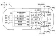
- FIG. 1 is a diagram for explaining a vehicle to which a vehicle control device as an embodiment is applied;
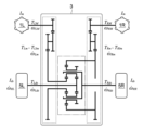
- FIG. FIG. 2 is a skeleton diagram showing the structure of the drive system of the vehicle shown in FIG. 1;
- 2 is a block diagram showing the configuration of a vehicle control device shown in FIG. 1;
- FIG. FIG. 2 is a map showing the relationship between weighting factors and vehicle speed set by an estimator in FIG. 1;
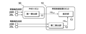
- FIG. FIG. 4 is a block diagram for explaining a modification of the vehicle control device shown in FIG. 3;
- a vehicle control device as an embodiment is applied to a vehicle 1 shown in FIG.
- the vehicle 1 includes wheels 5 (left and right wheels) arranged side by side in the vehicle width direction, a power distribution mechanism 3 that imparts a torque difference to these wheels 5, and a pair of electric motors 2 connected to the power distribution mechanism 3.
- alphabetic characters R and L added to numerical symbols indicate the arrangement positions (on the right or left side of the vehicle 1) of the elements corresponding to the symbols.
- 5R represents one of the wheels 5 located on the right side of the vehicle 1 (ie, right wheel)
- 5L represents the other located on the left side (ie, left wheel).
- the electric motor 2 has the function of driving at least one of the front wheels or the rear wheels of the vehicle 1, and can have the function of driving all four wheels.
- One of the pair of electric motors 2 arranged on the right side is also called a right electric motor 2R (right motor), and the other arranged on the left side is also called a left electric motor 2L (left motor).
- the right electric motor 2R and the left electric motor 2L operate independently of each other and can individually output driving forces of different magnitudes.
- These electric motors 2 are connected to a power distribution mechanism 3 via a pair of speed reduction mechanisms provided separately from each other.
- the right electric motor 2R and the left electric motor 2L of this embodiment have the same rated output and are provided in pairs.
- the vehicle 1 includes a power distribution mechanism 3 that amplifies the torque difference between the pair of electric motors 2 and distributes it to the left and right wheels 5 .
- the power distribution mechanism 3 of this embodiment is a differential mechanism having a yaw control function [AYC (Active Yaw Control) function], and the wheel shaft 4 (left wheel shaft 4L) connected to the left wheel 5L and the right wheel 5R It is interposed between the connected wheel axle 4 (right wheel axle 4R).
- the yaw control function is a function for stabilizing the posture of the vehicle 1 by actively controlling the sharing ratio of the driving force (driving torque) of the left and right wheels 5 to adjust the yaw moment.
- the power distribution mechanism 3 incorporates a planetary gear mechanism, a differential gear mechanism, and the like.
- a vehicle drive system including a pair of electric motors 2 and a power distribution mechanism 3 is also called a DM-AYC (Dual-Motor AYC) system.
- the power distribution mechanism 3 includes a pair of speed reduction mechanisms (gear trains enclosed by dashed lines in FIG. 2) that reduce the rotation speed of the electric motor 2, and a speed change mechanism (indicated by a dashed line in FIG. gear train enclosed).
- the reduction mechanism is a mechanism that increases the torque by reducing the torque (driving force) output from the electric motor 2 .
- the speed reduction ratio of the speed reduction mechanism is appropriately set according to the output characteristics and performance of the electric motor 2 . If the torque performance of the electric motor 2 is sufficiently high, the reduction mechanism may be omitted.
- the transmission mechanism is a mechanism that amplifies the torque difference transmitted to each of the wheels 5 .
- the transmission mechanism of the power distribution mechanism 3 shown in FIG. 2 includes a pair of planetary gear mechanisms. These planetary gear mechanisms have a structure in which the rotation shafts of planetary gears provided on respective carriers are connected to each other. Each carrier rotatably supports the planetary gears and supports the planetary gears so as to revolve between the sun gear and the ring gear. Driving forces transmitted from the left and right electric motors 2 are input to the ring gear and the sun gear of one planetary gear mechanism. The driving force transmitted to the wheels 5 is taken out from the sun gear and carrier of the other planetary gear mechanism. The ring gear of the other planetary gear mechanism is absent.
- the structure of the power distribution mechanism 3 shown in FIG. 2 is merely an example for realizing the yaw control function, and other known structures can be applied.
- Each electric motor 2L, 2R is electrically connected to a battery 7 via an inverter 6 (6L, 6R).
- the inverter 6 is a converter (DC-AC inverter) that mutually converts the power (DC power) of the DC circuit on the battery 7 side and the power (AC power) of the AC circuit on the electric motor 2 side.
- the battery 7 is, for example, a lithium-ion secondary battery or a nickel-hydrogen secondary battery, and is a secondary battery capable of supplying a high-voltage DC current of several hundred volts.
- DC power is converted into AC power by the inverter 6 and supplied to the electric motor 2 .
- the electric motor 2 When the electric motor 2 generates power, the generated power is converted into DC power by the inverter 6 and charged in the battery 7 .
- the operating state of inverter 6 is controlled by vehicle control device 10 .
- the vehicle control device 10 is one of the electronic control units (ECU, Electronic Control Unit) mounted on the vehicle 1 .
- the vehicle control device 10 incorporates a processor (central processing unit), a memory (main memory), a storage device (storage), an interface device, and the like, which are not shown, and these are communicably connected to each other via an internal bus.
- the contents of determinations and controls performed by the vehicle control device 10 are recorded and stored in the memory as firmware and application programs, and when the programs are executed, the contents of the programs are developed in the memory space and executed by the processor. .
- the vehicle control device 10 is connected with an accelerator opening sensor 21, a brake sensor 22, a steering angle sensor 23, a mode selection switch sensor 24, a resolver 25, and a wheel speed sensor 26, as shown in FIG.
- the accelerator opening sensor 21 is a sensor that detects the depression amount (accelerator opening) of the accelerator pedal and the depression speed thereof.
- the brake sensor 22 is a sensor that detects the amount of depression of the brake pedal (brake pedal stroke) and the depression speed thereof.
- the steering angle sensor 23 is a sensor that detects the steering angle of the wheels 5 (actual steering angle or steering angle). It is a device that integrates a switch for setting the snow mode, tarmac mode, etc., and a sensor that detects the operating state of the switch.
- the resolver 25 is a sensor that detects the rotational angular velocity of the electric motor 2 (that is, the motor angular velocities ⁇ Rm and ⁇ Lm ), and is provided for each electric motor 2 individually.
- the wheel speed sensor 26 is a sensor for detecting the rotational angular velocities (wheel angular velocities ⁇ Rds , ⁇ Lds ) output from the power distribution mechanism 3 to the wheel shaft 4 . It is provided near the location.
- the vehicle control device 10 controls the output of the pair of electric motors 2 by controlling the operating state of the inverter 6 based on the information detected by these sensors 21-26.
- the type of sensor that detects the rotational angular velocity of the electric motor 2 is not limited to the resolver 25, and may be another sensor (for example, a Hall sensor or an encoder).
- the vehicle control device 10 includes at least a first calculator 11, a second calculator 12, an estimator 13, and a controller 16 (FB controller).
- a calculation unit 14, a limiter 15, an FF control unit 17, a model calculation unit 18, and a driving force observer unit 19 are provided.
- These elements are shown by classifying the functions of the vehicle control device 10 for convenience. These elements can be described as independent programs, or can be described as a composite program combining multiple elements. A program corresponding to each element is stored in the memory or storage device of the vehicle control device 10 and executed by the processor.
- the first calculator 11 calculates a first vehicle body speed VB real based on the angular velocities of the wheels 5 (driving wheels) of the vehicle 1 (the wheel angular velocities ⁇ Lds and ⁇ Rds detected by the wheel speed sensors 26). .
- the first vehicle body speed VB real is calculated for each individual wheel 5 .
- the first vehicle body speed VB real is calculated as a value proportional to the product of the angular velocity of the wheel 5 and the effective radius r.
- the calculation cycle of the first vehicle body speed VB real is a cycle that depends on the accuracy (angular resolution) of the wheel speed sensor 26, the communication cycle in the communication path that connects the wheel speed sensor 26 and the vehicle control device 10, and the like. [ms].
- the second calculator 12 calculates the second vehicle body speed VB ref in a cycle shorter than that of the first calculator 11 based on the angular velocities of the electric motor 2 (motor angular velocities ⁇ Rm and ⁇ Lm detected by the resolver 25). be.
- the driving torques of the two wheels 5 (driving wheels) connected to those electric motors 2 are calculated.
- the estimated driving force that the wheels 5 transmit to the road surface is calculated.
- the quotient obtained by dividing the sum of the estimated driving forces by the weight M of the vehicle 1 is calculated, and the second vehicle body speed VB ref is calculated by integrating the quotient.
- the calculation cycle of the second vehicle body speed VB ref is set to at least a cycle shorter than that of the first calculation unit 11 (a cycle shorter than the calculation cycle of the first vehicle speed VB real in the first calculation unit 11).
- the resolver 25 and the vehicle control device 10 are connected by a dedicated line (hard wire), and the second vehicle body speed VB ref is calculated at a calculation cycle of about 1 to 2 [ms]. ing.
- the rotational speeds ( ⁇ Rds , ⁇ Lds ) of the wheels 5 are calculated from the motor angular velocities ⁇ Rm , ⁇ Lm based on the relationships shown in Equations (1) and (2).
- b 1 and b 2 in the formula are equivalent second speed ratios determined by the structure of the gears incorporated in the power distribution mechanism 3 .
- the drive torques T Rds and T Lds of the wheels 5 are calculated based on Equations (3) and (4).
- G is the speed reduction ratio of the speed reduction mechanism
- Im is the motor inertia
- T Rm and T Lm are the motor torques.
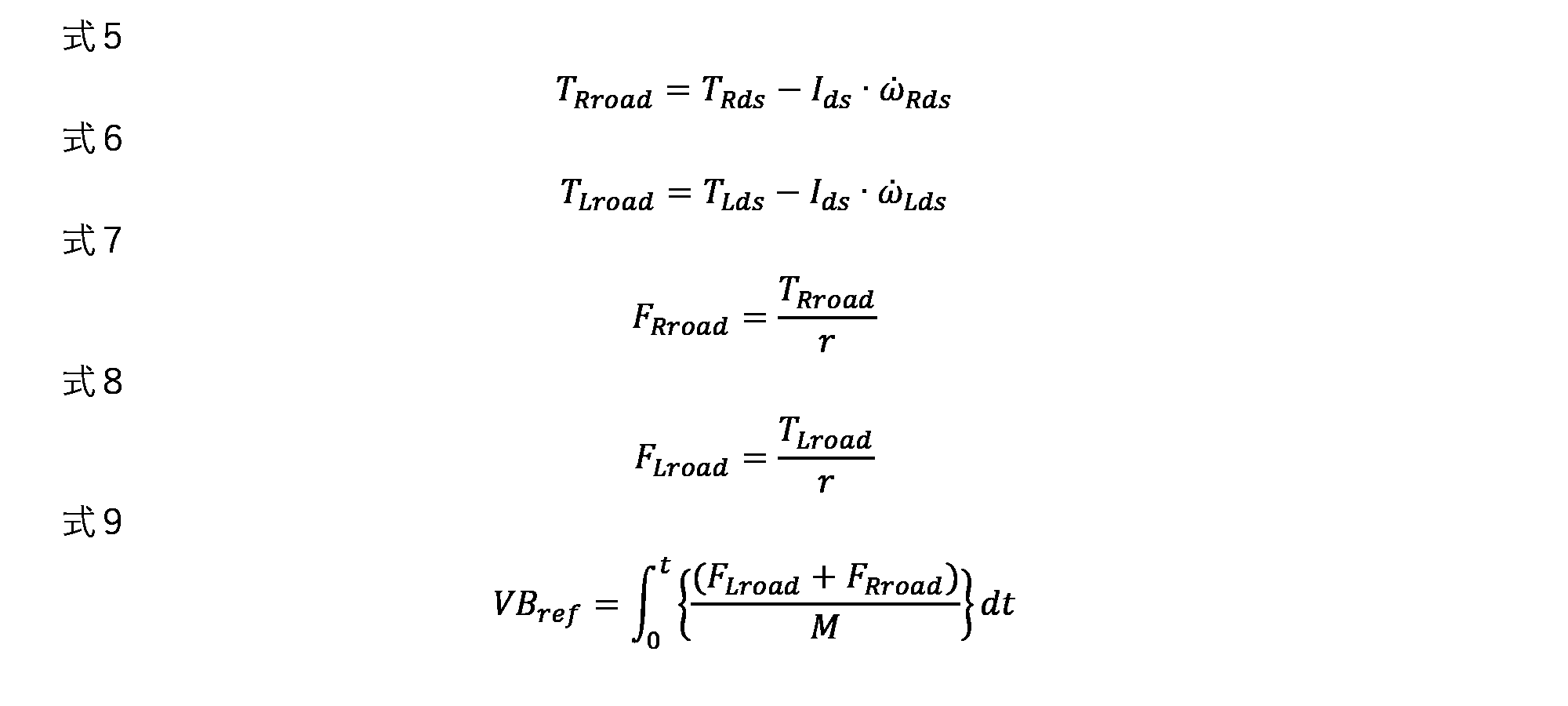
- the torques T Rroad and T Lroad transmitted from the wheels 5 to the road surface are calculated from the drive torques T Rds and T Lds of the wheels 5 and the inertia torque as shown in Equations (5) and (6). Ids in the formula is the inertia of the wheels 5 .
- the driving forces (estimated driving forces) F Rroad and F Lroad transmitted from the wheels 5 to the road surface are obtained by dividing the respective torques T Rroad and T Lroad by the effective radius r of the wheels 5 as shown in Equations 7 and 8. Calculated.
- the second vehicle body speed VB ref is calculated by integrating the quotient obtained by dividing the sum of the estimated driving forces F Rroad and F Lroad of the wheels 5 by the weight M of the vehicle 1, as shown in Equation (9).
- the estimator 13 estimates an estimated vehicle speed VB ctrl that is calculated using both the first vehicle speed VB real and the second vehicle speed VB ref according to the state of the vehicle 1 .
- the estimated vehicle speed VB ctrl is calculated as a weighted average value of the first vehicle speed VB real and the second vehicle speed VB ref as shown in Equation 10 below.
- W in the formula is a weighting factor for the first vehicle body speed VB real
- (1 ⁇ W) is a weighting factor for the second vehicle body speed VB ref .
- the conditions for estimating the estimated vehicle speed VB ctrl are, for example, that the vehicle 1 has just started (that a predetermined time has not passed since the start), or that the traveling speed (vehicle speed V) of the vehicle 1 is
- the driving mode of the vehicle 1 is the tarmac mode (the road surface is not slippery), and the like.
- Information on the estimated vehicle body speed VB ctrl calculated here is transmitted to the control unit 16 .
- a weight (value of a weighting factor) for each of the first vehicle speed VB real and the second vehicle speed VB ref is determined according to at least the state of the vehicle 1 .
- the value of the weighting factor is set according to the vehicle speed V, the elapsed time after the vehicle 1 starts, and the driving mode.
- the weighting factor W of the first vehicle speed VB real and the weighting factor (1-W) of the second vehicle speed VB ref are set based on the second vehicle speed VB ref .
- the value of the weighting factor W for the first vehicle speed VB real is set smaller as the first vehicle speed VB real or the second vehicle speed VB ref is lower. Therefore, the weighting factor (1-W) of the second vehicle speed VB ref is set to be larger as the first vehicle speed VB real or the second vehicle speed VB ref is lower.
- FIG. 4 is a graph illustrating the relationship between the weighting factor W of the first vehicle speed VB real and the vehicle speed V (eg, the first vehicle speed VB real or the second vehicle speed VB ref ).
- the weighting factor W is set to 0 when the vehicle speed V is less than the first predetermined value V1
- the weighting factor W is set to 0 when the vehicle speed V exceeds the second predetermined value V2 .
- Value is set to 1.
- the value of the weighting factor W is set large.
- a first weighting factor W1 having a value corresponding to the first vehicle speed VB real and a second weighting factor W2 having a value corresponding to the second vehicle speed VB ref are set, and the product of these is finalized. may be set as a specific weighting factor W.
- the first weighting factor W1 is set smaller, for example, as the first vehicle body speed VB real is lower.
- the second weighting factor W2 is also set smaller, for example, as the second vehicle body speed VB ref is lower.
- the weighting factor W of the first vehicle speed VB real is set small, and the weight of the second vehicle speed VB ref ( 1-W) can be set larger.
- the weighting coefficient W of the first vehicle body speed VB real may be set to a value close to 0, and the weight (1 ⁇ W) of the second vehicle speed VB ref may be set to a value close to 1.
- the detection signal related to the calculation of the estimated vehicle body speed VB ctrl is substantially switched from the wheel speed sensor 26 to the resolver 25 .
- the value of the first predetermined value V1 is at least 0 [km/h] or more, and is set to about 2 to 4 [km/h], for example.
- the value of the second predetermined value V2 is set to be at least greater than the first predetermined value V1 , and is set to approximately 6 to 10 [km/h], for example.
- the value of the weighting factor W may be increased at a constant gradient as the vehicle speed V increases.
- the setting may be such that the relationship between the weighting factor W and the vehicle speed V is drawn as a smooth curve.
- the calculation unit 14 individually calculates a target slip rate y (slip rate command value), which is a target value of the slip rate of the wheels 5 .
- the value of the target slip ratio y is calculated based on at least the required driving force of the vehicle 1 .
- the value of the target slip ratio y is calculated based on the required driving force of the vehicle 1 and the estimated driving force.
- the target slip ratio y is calculated based on the integrated value (error) obtained by subtracting the estimated driving force from the required driving force.
- the required driving force is calculated based on information detected by the sensors 21-26, for example.
- the value of the target slip ratio y calculated by the calculator 14 is excessive, the value is clipped to a range equal to or lower than the upper limit value y max set by the limiter 15, which will be described later. In this case, the value exceeding the upper limit value y max is discarded as a surplus value. Therefore, in order to reflect the value of this surplus in the next and subsequent calculations, a calculation configuration may be adopted in which the surplus value is multiplied by a predetermined gain, introduced again to the upstream side of the calculation unit 14, and subtracted from the required driving force. good.
- the limiting unit 15 individually sets the upper limit value y max of the target slip ratio y based on at least the vehicle speed V of the vehicle 1, and limits the target slip ratio y calculated by the calculating unit 14 to the upper limit value y max or less. It is.
- the vehicle speed V referred to here may be the first vehicle speed VB real , but is preferably the second vehicle speed VB ref .
- the upper limit value y max functions as a limiter for the target slip ratio y.
- the control unit 16 calculates the feedback control amount of the wheels 5 so that the wheel speed that becomes the target slip ratio y limited by the limiting unit 15 is obtained.
- the product of the value obtained by adding 1 to the target slip ratio y and the estimated vehicle body speed VB ctrl calculated by the estimator 13 is calculated.
- the value is divided by the effective radius r of the wheel 5 to calculate the desired angular velocity value ⁇ * of the wheel 5 .
- the torque feedback control amount ( For example, PI control amount) is calculated.
- an estimated value of the angular velocity ⁇ calculated by the model calculator 18 may be used instead of the angular velocity ⁇ in the previous calculation cycle.
- the FF control unit 17 calculates a feedforward control amount based on the required driving force of the wheels 5.
- the required driving force is multiplied by the effective radius r of the wheel 5 to calculate the required wheel torque for that wheel 5 .
- the sum of the required wheel torque calculated by the FF control unit 17 and the feedback control amount calculated by the control unit 16 is the final output torque T for the wheel 5 . Based on this output torque T, the operating state of the pair of electric motors 2 is controlled.
- the model calculation unit 18 calculates estimated values such as the vehicle speed, wheel speed (angular velocity ⁇ ), and vehicle body acceleration when the wheels 5 are driven with the output torque T, based on a predetermined vehicle model. These estimated values can be derived, for example, by applying a known arithmetic method for converting the torque of the electric motor 2 into the torque of the wheel shaft 4 .
- the driving force observer section 19 calculates an estimated driving force based on at least the output torque T.
- the inertia torque Jws of each wheel 5 is calculated based on the wheel speed calculated by the model calculation unit 18, for example.
- an estimated shaft torque is calculated by subtracting the inertia torque Jws from the output torque T. By dividing this estimated shaft torque by the effective radius r of the wheels 5, the estimated driving force is calculated.
- the above inertia torque J w s can also be calculated from the detected value of the resolver 25 .
- the wheel speeds of the wheels 5 (angular velocities ⁇ Rds , ⁇ Lds on the drive shaft side) of the wheels 5 are estimated from the motor angular velocities ⁇ Rm , ⁇ Lm detected by the resolver 25 based on Equations 1 and 2 above .
- the inertia torque Jws of each wheel 5 corresponds to the second term on the right side of Equations 3 and 4, so it can be calculated from each wheel speed.
- the estimated driving force is calculated by dividing the estimated shaft torque obtained by subtracting the inertia torque J ws from the output torque T by the effective radius r of the wheels 5 .
- the vehicle control device 10 is provided with the first calculator 11 , the second calculator 12 , the estimator 13 , and the controller 16 .
- the first calculator 11 calculates a first vehicle body speed VB real based on the angular velocities of the wheels 5 .
- the second calculator 12 calculates the second vehicle body speed VB ref at a cycle shorter than that of the first calculator 11 based on the angular velocity of the electric motor 2 .
- the estimating unit 13 estimates an estimated vehicle speed VB ctrl that is calculated using both the first vehicle speed VB real and the second vehicle speed VB ref according to the state of the vehicle 1 .
- the control unit 16 controls the electric motor 2 based on the estimated vehicle body speed VB ctrl estimated by the estimation unit 13 .
- the control responsiveness can be improved by reflecting the second vehicle body speed VB ref when the vehicle 1 starts or runs at an extremely low speed, for example, in the estimated vehicle body speed VB ctrl .
- the second vehicle body speed VB ref but also the first vehicle body speed VB real and the second vehicle body speed VB ref together, not only the operating state of the electric motor 2 but also the actual rotation state of the wheels 5 can be obtained. It can be properly reflected in the estimated vehicle body speed VB ctrl . Therefore, according to the above embodiment, the estimation accuracy of the estimated vehicle body speed VB ctrl can be improved, and the running performance of the vehicle 1 can be improved.
- the estimation unit 13 estimates the weighted average of the first vehicle speed VB real and the second vehicle speed VB ref as the estimated vehicle speed VB ctrl .
- each of the first vehicle body speed VB real and the second vehicle body speed VB ref can be reflected in the estimated vehicle body speed VB ctrl using weighting factors set according to a predetermined rule. Therefore, for example, sudden changes and unexpected fluctuations in the estimated vehicle speed VB ctrl can be suppressed, the stability of the estimated vehicle speed VB ctrl can be improved, and the running performance of the vehicle 1 can be improved.
- the weight (1-W) of the two-vehicle speed VB ref is set large.
- the weighting factor W of the first vehicle body speed VB real is set small
- the weight (1-W) of the vehicle speed VB ref may be set large.
- the detection signal related to the calculation of the estimated vehicle body speed VB ctrl is substantially switched from the wheel speed sensor 26 to the resolver 25.
- the second calculator 12 calculates the estimated driving force transmitted by the wheels 5 to the road surface based on the driving torques T Rds and T Lds of the wheels 5 derived from the angular velocity of the electric motor 2 and the inertia torque of the wheels 5.
- the second vehicle speed VB ref is calculated by calculating the forces F Rroad and F Lroad and integrating the quotient obtained by dividing the sum of the estimated driving forces F Rroad and F Lroad by the weight M of the vehicle 1 . With such a configuration, the second vehicle body speed VB ref can be calculated with high accuracy, and the running performance of the vehicle 1 can be improved.
- the vehicle 1 includes the power distribution mechanism 3 (differential mechanism) that imparts a torque difference to the wheels 5 (left and right wheels) and the pair of electric motors 2 connected to the power distribution mechanism 3.
- a vehicle control device 10 is applied.
- the vehicle control device 10 individually controls the slip states of the wheels 5 (left and right wheels) by controlling the operating states of the pair of electric motors 2 . ) individually.
- the difference between the estimated slip amount and the actual slip amount can be reduced, and the magnitude of the suppression torque for suppressing the slip of the wheels 5 can be set with high accuracy. For example, it is possible to prevent the problem that the suppression torque becomes excessive when the vehicle 1 starts, and improve the starting performance (driving performance) of the vehicle 1 .
- the vehicle control device 10 applied to the rear wheels of the vehicle 1 was illustrated, but a similar vehicle control device may be applied to the front wheels, or the same vehicle control device may be applied to both the front and rear wheels. Apparatus may be applied.
- the vehicle control device 10 for controlling the electric motor 2 of the vehicle 1 having the power distribution mechanism 3 is illustrated, but application to the vehicle 1 without the power distribution mechanism 3 is also possible. By applying the vehicle control device 10 to at least the vehicle 1 having the electric motor 2 that drives the wheels 5, the same effects as those of the above embodiment can be obtained.
- the first calculation unit 11 and the second calculation unit 12 are included in the same vehicle control device 10 .
- Each element can be separated individually, and the function of each element can be assigned to a plurality of electronic controllers.
- the first calculation unit 11 is incorporated in a PHEV-ECU 30 (second vehicle control device) provided separately from the vehicle control device 10, and the vehicle control device 10 includes the second calculation unit 12 and the estimation unit 13 may be incorporated.
- the transmission cycle of the first vehicle body speed VB real to the estimator 13 will become longer.
- the above embodiment by controlling the electric motor 2 using the estimated vehicle speed VB ctrl calculated using both the first vehicle speed VB real and the second vehicle speed VB ref , the above embodiment It can produce the same effect as.
Landscapes
- Engineering & Computer Science (AREA)
- Transportation (AREA)
- Mechanical Engineering (AREA)
- Chemical & Material Sciences (AREA)
- Combustion & Propulsion (AREA)
- Power Engineering (AREA)
- Life Sciences & Earth Sciences (AREA)
- Sustainable Development (AREA)
- Sustainable Energy (AREA)
- Physics & Mathematics (AREA)
- General Physics & Mathematics (AREA)
- Electric Propulsion And Braking For Vehicles (AREA)
Abstract
Description
一方、一般的な車輪速センサの検出信号は、電動機の動作に対して遅れて応答する。例えば、車輪の回転状態は、電動機から出力される駆動力が車輪に伝達され、その車輪を介して駆動力が路面に伝達されることによって初めて変化する。そのため、電動機の動作に対して車輪速センサの検出信号の変化は遅れやすく、良好な制御応答性が得られないことがある。そこで、車輪速の代わりに電動機の回転状態をレゾルバで検出し、レゾルバの検出信号に基づいて車体速を推定することが提案されている(特許文献2参照)。
ここで開示する車両制御装置は、車両の車輪を駆動する電動機を制御するための車両制御装置であって、前記車輪の第一回転速度に基づき、第一車体速を算出する第一算出部と、前記電動機の第二回転速度に基づき、前記第一算出部よりも短い周期で第二車体速を算出する第二算出部と、前記車両の状態に応じて、前記第一車体速及び前記第二車体速を併用して算出される推定車体速を推定する推定部と、前記推定部で推定された前記推定車体速に基づき前記電動機を制御する制御部とを備える。
実施例としての車両制御装置は、図1に示す車両1に適用される。車両1は、車幅方向に並んで配置される車輪5(左右輪)と、これらの車輪5にトルク差を付与する動力分配機構3と、動力分配機構3に接続される一対の電動機2とを具備する。図中において数字符号に付加されるアルファベットのR,Lは、当該符号にかかる要素の配設位置(車両1の右側や左側にあること)を表す。例えば、5Rは車輪5のうち車両1の右側(Right)に位置する一方(すなわち右輪)を表し、5Lは左側(Left)に位置する他方(すなわち左輪)を表す。
図1に示すように、車両制御装置10の内部には、少なくとも第一算出部11,第二算出部12,推定部13,制御部16(FB制御部)が設けられる。本実施例では、図3に示すように、上記の要素に加えて、演算部14,制限部15,FF制御部17,モデル算出部18,駆動力オブザーバ部19が設けられる。これらの要素は、車両制御装置10の機能を便宜的に分類して示したものである。これらの要素は独立したプログラムとして記述することができ、複数の要素を合体させた複合プログラムとして記述することもできる。各要素に相当するプログラムは、車両制御装置10のメモリや記憶装置に記憶され、プロセッサで実行される。


(1)上記の実施例では、車両制御装置10に第一算出部11と第二算出部12と推定部13と制御部16とが設けられる。第一算出部11は、車輪5の角速度に基づき、第一車体速VBrealを算出する。第二算出部12は、電動機2の角速度に基づき、第一算出部11よりも短い周期で第二車体速VBrefを算出する。推定部13は、車両1の状態に応じて、第一車体速VBreal及び第二車体速VBrefを併用して算出される推定車体速VBctrlを推定する。制御部16は、推定部13で推定された推定車体速VBctrlに基づき電動機2を制御する。
上記の実施例はあくまでも例示に過ぎず、本実施例で明示しない種々の変形や技術の適用を排除する意図はない。本実施例の各構成は、それらの趣旨を逸脱しない範囲で種々変形して実施することができる。また、必要に応じて取捨選択することができ、あるいは適宜組み合わせることができる。
2 電動機
3 動力分配機構
4 車輪軸
5 車輪(左右輪)
6 インバータ
7 バッテリ
10 車両制御装置(ECU)
11 第一算出部
12 第二算出部
13 推定部
14 演算部
15 制限部
16 制御部(FB制御部)
17 FF制御部
18 モデル算出部
19 駆動力オブザーバ部
21 アクセル開度センサ
22 ブレーキセンサ
23 舵角センサ
24 モード選択スイッチセンサ
25 レゾルバ
26 車輪速センサ
30 PHEV-ECU
VBreal 第一車体速
VBref 第二車体速
VBctrl 推定車体速
Claims (6)
- 車両の車輪を駆動する電動機を制御するための車両制御装置において、
前記車輪の角速度に基づき、第一車体速を算出する第一算出部と、
前記電動機の角速度に基づき、前記第一算出部よりも短い周期で第二車体速を算出する第二算出部と、
前記車両の状態に応じて、前記第一車体速及び前記第二車体速を併用して算出される推定車体速を推定する推定部と、
前記推定部で推定された前記推定車体速に基づき前記電動機を制御する制御部と
を備えることを特徴とする、車両制御装置。 - 前記推定部が、前記第一車体速及び前記第二車体速の加重平均を前記推定車体速として推定する
ことを特徴とする、請求項1に記載の車両制御装置。 - 前記推定部が、前記加重平均の算出に際し、前記第一車体速が低速であるほど、または、前記第二車体速が低速であるほど、前記第一車体速の重みを小さく設定するとともに前記第二車体速の重みを大きく設定する
ことを特徴とする、請求項2に記載の車両制御装置。 - 前記推定部が、前記車輪の角速度を検出する車輪速センサの異常時には、前記第二車体速の重みを大きく設定する
ことを特徴とする、請求項2に記載の車両制御装置。 - 前記第二算出部が、前記電動機の角速度から導出される前記車輪の駆動トルク及び前記車輪のイナーシャトルクに基づき前記車輪が路面に伝える推定駆動力を算出するとともに、前記推定駆動力の和を前記車両の重量で除した商を積分することで前記第二車体速を算出する
ことを特徴とする、請求項1~4のいずれか1項に記載の車両制御装置。 - 左右輪にトルク差を付与する差動機構と前記差動機構に接続される一対の電動機とを具備する前記車両において、前記一対の電動機の作動状態を制御することで前記左右輪のスリップ状態を個別に制御する車両制御装置であって、
前記制御部が、前記推定車体速を用いて前記左右輪のスリップ状態を個別に制御する
ことを特徴とする、請求項1~5のいずれか1項に記載の車両制御装置。
Priority Applications (4)
| Application Number | Priority Date | Filing Date | Title |
|---|---|---|---|
| JP2023540322A JP7537621B2 (ja) | 2021-08-06 | 2022-08-01 | 車両制御装置 |
| EP22852985.5A EP4353513A4 (en) | 2021-08-06 | 2022-08-01 | Vehicle control device |
| US18/573,780 US20240317205A1 (en) | 2021-08-06 | 2022-08-01 | Vehicle control device |
| CN202280043053.4A CN117693437A (zh) | 2021-08-06 | 2022-08-01 | 车辆的控制系统 |
Applications Claiming Priority (2)
| Application Number | Priority Date | Filing Date | Title |
|---|---|---|---|
| JP2021129863 | 2021-08-06 | ||
| JP2021-129863 | 2021-08-06 |
Publications (1)
| Publication Number | Publication Date |
|---|---|
| WO2023013566A1 true WO2023013566A1 (ja) | 2023-02-09 |
Family
ID=85154749
Family Applications (1)
| Application Number | Title | Priority Date | Filing Date |
|---|---|---|---|
| PCT/JP2022/029415 Ceased WO2023013566A1 (ja) | 2021-08-06 | 2022-08-01 | 車両制御装置 |
Country Status (5)
| Country | Link |
|---|---|
| US (1) | US20240317205A1 (ja) |
| EP (1) | EP4353513A4 (ja) |
| JP (1) | JP7537621B2 (ja) |
| CN (1) | CN117693437A (ja) |
| WO (1) | WO2023013566A1 (ja) |
Cited By (1)
| Publication number | Priority date | Publication date | Assignee | Title |
|---|---|---|---|---|
| US20230311904A1 (en) * | 2022-04-04 | 2023-10-05 | GM Global Technology Operations LLC | Vehicle speed and/or wheel speed estimation using multiple speed measurements |
Citations (5)
| Publication number | Priority date | Publication date | Assignee | Title |
|---|---|---|---|---|
| JP2000309230A (ja) * | 1999-02-23 | 2000-11-07 | Honda Motor Co Ltd | 車両用電動式駆動装置 |
| JP2007049825A (ja) * | 2005-08-10 | 2007-02-22 | Hitachi Ltd | 電動車両の走行制御装置および電動走行制御システム |
| JP4637136B2 (ja) | 2007-05-23 | 2011-02-23 | 本田技研工業株式会社 | 動力装置 |
| JP2017073921A (ja) | 2015-10-09 | 2017-04-13 | 日立オートモティブシステムズ株式会社 | 電動車両の制御装置、電動車両の制御システム及び電動車両の制御方法 |
| JP2020162373A (ja) * | 2019-03-27 | 2020-10-01 | 日産自動車株式会社 | 電動車両の制御方法及び制御装置 |
Family Cites Families (6)
| Publication number | Priority date | Publication date | Assignee | Title |
|---|---|---|---|---|
| CN102149597A (zh) * | 2008-10-22 | 2011-08-10 | 株式会社爱考斯研究 | 车辆 |
| US8453770B2 (en) * | 2009-01-29 | 2013-06-04 | Tesla Motors, Inc. | Dual motor drive and control system for an electric vehicle |
| JP5455716B2 (ja) * | 2010-03-09 | 2014-03-26 | 本田技研工業株式会社 | ハイブリッド車両用駆動装置の制御装置 |
| JP6172121B2 (ja) * | 2014-11-14 | 2017-08-02 | トヨタ自動車株式会社 | 燃料電池システム、燃料電池車両、および、燃料電池システムの制御方法 |
| JP6233608B2 (ja) * | 2015-10-13 | 2017-11-22 | トヨタ自動車株式会社 | 車両の駆動力制御装置 |
| JP7158456B2 (ja) * | 2020-12-02 | 2022-10-21 | 本田技研工業株式会社 | 走行制御システム及び走行制御方法 |
-
2022
- 2022-08-01 WO PCT/JP2022/029415 patent/WO2023013566A1/ja not_active Ceased
- 2022-08-01 CN CN202280043053.4A patent/CN117693437A/zh active Pending
- 2022-08-01 US US18/573,780 patent/US20240317205A1/en active Pending
- 2022-08-01 JP JP2023540322A patent/JP7537621B2/ja active Active
- 2022-08-01 EP EP22852985.5A patent/EP4353513A4/en active Pending
Patent Citations (5)
| Publication number | Priority date | Publication date | Assignee | Title |
|---|---|---|---|---|
| JP2000309230A (ja) * | 1999-02-23 | 2000-11-07 | Honda Motor Co Ltd | 車両用電動式駆動装置 |
| JP2007049825A (ja) * | 2005-08-10 | 2007-02-22 | Hitachi Ltd | 電動車両の走行制御装置および電動走行制御システム |
| JP4637136B2 (ja) | 2007-05-23 | 2011-02-23 | 本田技研工業株式会社 | 動力装置 |
| JP2017073921A (ja) | 2015-10-09 | 2017-04-13 | 日立オートモティブシステムズ株式会社 | 電動車両の制御装置、電動車両の制御システム及び電動車両の制御方法 |
| JP2020162373A (ja) * | 2019-03-27 | 2020-10-01 | 日産自動車株式会社 | 電動車両の制御方法及び制御装置 |
Non-Patent Citations (1)
| Title |
|---|
| See also references of EP4353513A4 |
Cited By (2)
| Publication number | Priority date | Publication date | Assignee | Title |
|---|---|---|---|---|
| US20230311904A1 (en) * | 2022-04-04 | 2023-10-05 | GM Global Technology Operations LLC | Vehicle speed and/or wheel speed estimation using multiple speed measurements |
| US12151687B2 (en) * | 2022-04-04 | 2024-11-26 | GM Global Technology Operations LLC | Vehicle speed and/or wheel speed estimation using multiple speed measurements |
Also Published As
| Publication number | Publication date |
|---|---|
| JPWO2023013566A1 (ja) | 2023-02-09 |
| CN117693437A (zh) | 2024-03-12 |
| JP7537621B2 (ja) | 2024-08-21 |
| US20240317205A1 (en) | 2024-09-26 |
| EP4353513A1 (en) | 2024-04-17 |
| EP4353513A4 (en) | 2024-10-09 |
Similar Documents
| Publication | Publication Date | Title |
|---|---|---|
| WO2023013565A1 (ja) | 車両制御装置 | |
| JP6333917B2 (ja) | 車両の旋回制御装置 | |
| RU2729837C1 (ru) | Способ и устройство управления электромотором для транспортного средства с электроприводом | |
| JP6546199B2 (ja) | 駆動装置の制御装置及び制御方法ならびに記録媒体 | |
| US20160221446A1 (en) | Driving force control device and driving force control method | |
| JP2017093003A (ja) | スリップ制御装置 | |
| CN107848526A (zh) | 车辆转弯控制装置 | |
| JP7056219B2 (ja) | 電動車両の制御方法および電動車両の制御装置 | |
| KR102777753B1 (ko) | 차량의 휠 슬립 제어 방법 | |
| JP2019055643A (ja) | 車両制御装置 | |
| JP7207607B2 (ja) | 車両制御装置 | |
| CN112477619A (zh) | 车辆的控制装置 | |
| CN114291053B (zh) | 车辆的车轮滑动控制方法 | |
| JP2008011609A (ja) | 電気駆動車両 | |
| JP7809300B2 (ja) | 設計手法及び車両制御装置 | |
| WO2023032012A1 (ja) | 電動車両の制御方法及び電動車両の制御装置 | |
| JP7537621B2 (ja) | 車両制御装置 | |
| KR20240033823A (ko) | 차량의 주행 제어 방법 | |
| JP2022057096A (ja) | 車両の制御装置 | |
| JP2021146950A (ja) | 車両の旋回制御装置 | |
| JP2003070107A (ja) | 電気自動車のモータ制御装置 | |
| JP3713995B2 (ja) | 車両用走行制御装置 | |
| JP2018129890A (ja) | 車両の出力制御装置 | |
| JP7480661B2 (ja) | 車両の制御装置 | |
| JP2016137740A (ja) | 車両制御装置 |
Legal Events
| Date | Code | Title | Description |
|---|---|---|---|
| 121 | Ep: the epo has been informed by wipo that ep was designated in this application |
Ref document number: 22852985 Country of ref document: EP Kind code of ref document: A1 |
|
| WWE | Wipo information: entry into national phase |
Ref document number: 2023540322 Country of ref document: JP |
|
| WWE | Wipo information: entry into national phase |
Ref document number: 202280043053.4 Country of ref document: CN |
|
| WWE | Wipo information: entry into national phase |
Ref document number: 18573780 Country of ref document: US |
|
| WWE | Wipo information: entry into national phase |
Ref document number: 2022852985 Country of ref document: EP |
|
| WWE | Wipo information: entry into national phase |
Ref document number: 2401000708 Country of ref document: TH |
|
| ENP | Entry into the national phase |
Ref document number: 2022852985 Country of ref document: EP Effective date: 20240108 |
|
| NENP | Non-entry into the national phase |
Ref country code: DE |