WO2023013693A1 - 排気ガス処理装置 - Google Patents
排気ガス処理装置 Download PDFInfo
- Publication number
- WO2023013693A1 WO2023013693A1 PCT/JP2022/029838 JP2022029838W WO2023013693A1 WO 2023013693 A1 WO2023013693 A1 WO 2023013693A1 JP 2022029838 W JP2022029838 W JP 2022029838W WO 2023013693 A1 WO2023013693 A1 WO 2023013693A1
- Authority
- WO
- WIPO (PCT)
- Prior art keywords
- exhaust gas
- case
- treatment device
- inlet
- heater
- Prior art date
- Legal status (The legal status is an assumption and is not a legal conclusion. Google has not performed a legal analysis and makes no representation as to the accuracy of the status listed.)
- Ceased
Links
Images









Classifications
-
- F—MECHANICAL ENGINEERING; LIGHTING; HEATING; WEAPONS; BLASTING
- F01—MACHINES OR ENGINES IN GENERAL; ENGINE PLANTS IN GENERAL; STEAM ENGINES
- F01N—GAS-FLOW SILENCERS OR EXHAUST APPARATUS FOR MACHINES OR ENGINES IN GENERAL; GAS-FLOW SILENCERS OR EXHAUST APPARATUS FOR INTERNAL-COMBUSTION ENGINES
- F01N3/00—Exhaust or silencing apparatus having means for purifying, rendering innocuous, or otherwise treating exhaust
- F01N3/08—Exhaust or silencing apparatus having means for purifying, rendering innocuous, or otherwise treating exhaust for rendering innocuous
- F01N3/10—Exhaust or silencing apparatus having means for purifying, rendering innocuous, or otherwise treating exhaust for rendering innocuous by thermal or catalytic conversion of noxious components of exhaust
- F01N3/18—Exhaust or silencing apparatus having means for purifying, rendering innocuous, or otherwise treating exhaust for rendering innocuous by thermal or catalytic conversion of noxious components of exhaust characterised by methods of operation; Control
- F01N3/20—Exhaust or silencing apparatus having means for purifying, rendering innocuous, or otherwise treating exhaust for rendering innocuous by thermal or catalytic conversion of noxious components of exhaust characterised by methods of operation; Control specially adapted for catalytic conversion
- F01N3/2006—Periodically heating or cooling catalytic reactors, e.g. at cold starting or overheating
- F01N3/2013—Periodically heating or cooling catalytic reactors, e.g. at cold starting or overheating using electric or magnetic heating means
-
- B—PERFORMING OPERATIONS; TRANSPORTING
- B01—PHYSICAL OR CHEMICAL PROCESSES OR APPARATUS IN GENERAL
- B01D—SEPARATION
- B01D53/00—Separation of gases or vapours; Recovering vapours of volatile solvents from gases; Chemical or biological purification of waste gases, e.g. engine exhaust gases, smoke, fumes, flue gases, aerosols
- B01D53/34—Chemical or biological purification of waste gases
- B01D53/92—Chemical or biological purification of waste gases of engine exhaust gases
- B01D53/94—Chemical or biological purification of waste gases of engine exhaust gases by catalytic processes
- B01D53/9495—Controlling the catalytic process
-
- F—MECHANICAL ENGINEERING; LIGHTING; HEATING; WEAPONS; BLASTING
- F01—MACHINES OR ENGINES IN GENERAL; ENGINE PLANTS IN GENERAL; STEAM ENGINES
- F01N—GAS-FLOW SILENCERS OR EXHAUST APPARATUS FOR MACHINES OR ENGINES IN GENERAL; GAS-FLOW SILENCERS OR EXHAUST APPARATUS FOR INTERNAL-COMBUSTION ENGINES
- F01N13/00—Exhaust or silencing apparatus characterised by constructional features
- F01N13/08—Other arrangements or adaptations of exhaust conduits
- F01N13/10—Other arrangements or adaptations of exhaust conduits of exhaust manifolds
-
- F—MECHANICAL ENGINEERING; LIGHTING; HEATING; WEAPONS; BLASTING
- F01—MACHINES OR ENGINES IN GENERAL; ENGINE PLANTS IN GENERAL; STEAM ENGINES
- F01N—GAS-FLOW SILENCERS OR EXHAUST APPARATUS FOR MACHINES OR ENGINES IN GENERAL; GAS-FLOW SILENCERS OR EXHAUST APPARATUS FOR INTERNAL-COMBUSTION ENGINES
- F01N3/00—Exhaust or silencing apparatus having means for purifying, rendering innocuous, or otherwise treating exhaust
- F01N3/08—Exhaust or silencing apparatus having means for purifying, rendering innocuous, or otherwise treating exhaust for rendering innocuous
- F01N3/10—Exhaust or silencing apparatus having means for purifying, rendering innocuous, or otherwise treating exhaust for rendering innocuous by thermal or catalytic conversion of noxious components of exhaust
- F01N3/24—Exhaust or silencing apparatus having means for purifying, rendering innocuous, or otherwise treating exhaust for rendering innocuous by thermal or catalytic conversion of noxious components of exhaust characterised by constructional aspects of converting apparatus
-
- F—MECHANICAL ENGINEERING; LIGHTING; HEATING; WEAPONS; BLASTING
- F01—MACHINES OR ENGINES IN GENERAL; ENGINE PLANTS IN GENERAL; STEAM ENGINES
- F01N—GAS-FLOW SILENCERS OR EXHAUST APPARATUS FOR MACHINES OR ENGINES IN GENERAL; GAS-FLOW SILENCERS OR EXHAUST APPARATUS FOR INTERNAL-COMBUSTION ENGINES
- F01N3/00—Exhaust or silencing apparatus having means for purifying, rendering innocuous, or otherwise treating exhaust
- F01N3/08—Exhaust or silencing apparatus having means for purifying, rendering innocuous, or otherwise treating exhaust for rendering innocuous
- F01N3/10—Exhaust or silencing apparatus having means for purifying, rendering innocuous, or otherwise treating exhaust for rendering innocuous by thermal or catalytic conversion of noxious components of exhaust
- F01N3/24—Exhaust or silencing apparatus having means for purifying, rendering innocuous, or otherwise treating exhaust for rendering innocuous by thermal or catalytic conversion of noxious components of exhaust characterised by constructional aspects of converting apparatus
- F01N3/28—Construction of catalytic reactors
- F01N3/2803—Construction of catalytic reactors characterised by structure, by material or by manufacturing of catalyst support
-
- B—PERFORMING OPERATIONS; TRANSPORTING
- B01—PHYSICAL OR CHEMICAL PROCESSES OR APPARATUS IN GENERAL
- B01D—SEPARATION
- B01D2259/00—Type of treatment
- B01D2259/45—Gas separation or purification devices adapted for specific applications
- B01D2259/4566—Gas separation or purification devices adapted for specific applications for use in transportation means
-
- F—MECHANICAL ENGINEERING; LIGHTING; HEATING; WEAPONS; BLASTING
- F01—MACHINES OR ENGINES IN GENERAL; ENGINE PLANTS IN GENERAL; STEAM ENGINES
- F01N—GAS-FLOW SILENCERS OR EXHAUST APPARATUS FOR MACHINES OR ENGINES IN GENERAL; GAS-FLOW SILENCERS OR EXHAUST APPARATUS FOR INTERNAL-COMBUSTION ENGINES
- F01N13/00—Exhaust or silencing apparatus characterised by constructional features
- F01N13/009—Exhaust or silencing apparatus characterised by constructional features having two or more separate purifying devices arranged in series
-
- F—MECHANICAL ENGINEERING; LIGHTING; HEATING; WEAPONS; BLASTING
- F01—MACHINES OR ENGINES IN GENERAL; ENGINE PLANTS IN GENERAL; STEAM ENGINES
- F01N—GAS-FLOW SILENCERS OR EXHAUST APPARATUS FOR MACHINES OR ENGINES IN GENERAL; GAS-FLOW SILENCERS OR EXHAUST APPARATUS FOR INTERNAL-COMBUSTION ENGINES
- F01N2240/00—Combination or association of two or more different exhaust treating devices, or of at least one such device with an auxiliary device, not covered by indexing codes F01N2230/00 or F01N2250/00, one of the devices being
- F01N2240/16—Combination or association of two or more different exhaust treating devices, or of at least one such device with an auxiliary device, not covered by indexing codes F01N2230/00 or F01N2250/00, one of the devices being an electric heater, i.e. a resistance heater
-
- F—MECHANICAL ENGINEERING; LIGHTING; HEATING; WEAPONS; BLASTING
- F01—MACHINES OR ENGINES IN GENERAL; ENGINE PLANTS IN GENERAL; STEAM ENGINES
- F01N—GAS-FLOW SILENCERS OR EXHAUST APPARATUS FOR MACHINES OR ENGINES IN GENERAL; GAS-FLOW SILENCERS OR EXHAUST APPARATUS FOR INTERNAL-COMBUSTION ENGINES
- F01N2470/00—Structure or shape of exhaust gas passages, pipes or tubes
-
- F—MECHANICAL ENGINEERING; LIGHTING; HEATING; WEAPONS; BLASTING
- F01—MACHINES OR ENGINES IN GENERAL; ENGINE PLANTS IN GENERAL; STEAM ENGINES
- F01N—GAS-FLOW SILENCERS OR EXHAUST APPARATUS FOR MACHINES OR ENGINES IN GENERAL; GAS-FLOW SILENCERS OR EXHAUST APPARATUS FOR INTERNAL-COMBUSTION ENGINES
- F01N2900/00—Details of electrical control or of the monitoring of the exhaust gas treating apparatus
- F01N2900/06—Parameters used for exhaust control or diagnosing
- F01N2900/10—Parameters used for exhaust control or diagnosing said parameters being related to the vehicle or its components
- F01N2900/104—Battery status
-
- F—MECHANICAL ENGINEERING; LIGHTING; HEATING; WEAPONS; BLASTING
- F01—MACHINES OR ENGINES IN GENERAL; ENGINE PLANTS IN GENERAL; STEAM ENGINES
- F01N—GAS-FLOW SILENCERS OR EXHAUST APPARATUS FOR MACHINES OR ENGINES IN GENERAL; GAS-FLOW SILENCERS OR EXHAUST APPARATUS FOR INTERNAL-COMBUSTION ENGINES
- F01N2900/00—Details of electrical control or of the monitoring of the exhaust gas treating apparatus
- F01N2900/06—Parameters used for exhaust control or diagnosing
- F01N2900/12—Parameters used for exhaust control or diagnosing said parameters being related to the vehicle exterior
-
- F—MECHANICAL ENGINEERING; LIGHTING; HEATING; WEAPONS; BLASTING
- F01—MACHINES OR ENGINES IN GENERAL; ENGINE PLANTS IN GENERAL; STEAM ENGINES
- F01N—GAS-FLOW SILENCERS OR EXHAUST APPARATUS FOR MACHINES OR ENGINES IN GENERAL; GAS-FLOW SILENCERS OR EXHAUST APPARATUS FOR INTERNAL-COMBUSTION ENGINES
- F01N2900/00—Details of electrical control or of the monitoring of the exhaust gas treating apparatus
- F01N2900/06—Parameters used for exhaust control or diagnosing
- F01N2900/16—Parameters used for exhaust control or diagnosing said parameters being related to the exhaust apparatus, e.g. particulate filter or catalyst
- F01N2900/1602—Temperature of exhaust gas apparatus
-
- F—MECHANICAL ENGINEERING; LIGHTING; HEATING; WEAPONS; BLASTING
- F01—MACHINES OR ENGINES IN GENERAL; ENGINE PLANTS IN GENERAL; STEAM ENGINES
- F01N—GAS-FLOW SILENCERS OR EXHAUST APPARATUS FOR MACHINES OR ENGINES IN GENERAL; GAS-FLOW SILENCERS OR EXHAUST APPARATUS FOR INTERNAL-COMBUSTION ENGINES
- F01N3/00—Exhaust or silencing apparatus having means for purifying, rendering innocuous, or otherwise treating exhaust
- F01N3/02—Exhaust or silencing apparatus having means for purifying, rendering innocuous, or otherwise treating exhaust for cooling, or for removing solid constituents of, exhaust
- F01N3/021—Exhaust or silencing apparatus having means for purifying, rendering innocuous, or otherwise treating exhaust for cooling, or for removing solid constituents of, exhaust by means of filters
-
- F—MECHANICAL ENGINEERING; LIGHTING; HEATING; WEAPONS; BLASTING
- F01—MACHINES OR ENGINES IN GENERAL; ENGINE PLANTS IN GENERAL; STEAM ENGINES
- F01N—GAS-FLOW SILENCERS OR EXHAUST APPARATUS FOR MACHINES OR ENGINES IN GENERAL; GAS-FLOW SILENCERS OR EXHAUST APPARATUS FOR INTERNAL-COMBUSTION ENGINES
- F01N3/00—Exhaust or silencing apparatus having means for purifying, rendering innocuous, or otherwise treating exhaust
- F01N3/08—Exhaust or silencing apparatus having means for purifying, rendering innocuous, or otherwise treating exhaust for rendering innocuous
- F01N3/10—Exhaust or silencing apparatus having means for purifying, rendering innocuous, or otherwise treating exhaust for rendering innocuous by thermal or catalytic conversion of noxious components of exhaust
- F01N3/101—Three-way catalysts
-
- F—MECHANICAL ENGINEERING; LIGHTING; HEATING; WEAPONS; BLASTING
- F01—MACHINES OR ENGINES IN GENERAL; ENGINE PLANTS IN GENERAL; STEAM ENGINES
- F01N—GAS-FLOW SILENCERS OR EXHAUST APPARATUS FOR MACHINES OR ENGINES IN GENERAL; GAS-FLOW SILENCERS OR EXHAUST APPARATUS FOR INTERNAL-COMBUSTION ENGINES
- F01N3/00—Exhaust or silencing apparatus having means for purifying, rendering innocuous, or otherwise treating exhaust
- F01N3/08—Exhaust or silencing apparatus having means for purifying, rendering innocuous, or otherwise treating exhaust for rendering innocuous
- F01N3/10—Exhaust or silencing apparatus having means for purifying, rendering innocuous, or otherwise treating exhaust for rendering innocuous by thermal or catalytic conversion of noxious components of exhaust
- F01N3/18—Exhaust or silencing apparatus having means for purifying, rendering innocuous, or otherwise treating exhaust for rendering innocuous by thermal or catalytic conversion of noxious components of exhaust characterised by methods of operation; Control
- F01N3/20—Exhaust or silencing apparatus having means for purifying, rendering innocuous, or otherwise treating exhaust for rendering innocuous by thermal or catalytic conversion of noxious components of exhaust characterised by methods of operation; Control specially adapted for catalytic conversion
- F01N3/2006—Periodically heating or cooling catalytic reactors, e.g. at cold starting or overheating
-
- F—MECHANICAL ENGINEERING; LIGHTING; HEATING; WEAPONS; BLASTING
- F01—MACHINES OR ENGINES IN GENERAL; ENGINE PLANTS IN GENERAL; STEAM ENGINES
- F01N—GAS-FLOW SILENCERS OR EXHAUST APPARATUS FOR MACHINES OR ENGINES IN GENERAL; GAS-FLOW SILENCERS OR EXHAUST APPARATUS FOR INTERNAL-COMBUSTION ENGINES
- F01N3/00—Exhaust or silencing apparatus having means for purifying, rendering innocuous, or otherwise treating exhaust
- F01N3/08—Exhaust or silencing apparatus having means for purifying, rendering innocuous, or otherwise treating exhaust for rendering innocuous
- F01N3/10—Exhaust or silencing apparatus having means for purifying, rendering innocuous, or otherwise treating exhaust for rendering innocuous by thermal or catalytic conversion of noxious components of exhaust
- F01N3/18—Exhaust or silencing apparatus having means for purifying, rendering innocuous, or otherwise treating exhaust for rendering innocuous by thermal or catalytic conversion of noxious components of exhaust characterised by methods of operation; Control
- F01N3/20—Exhaust or silencing apparatus having means for purifying, rendering innocuous, or otherwise treating exhaust for rendering innocuous by thermal or catalytic conversion of noxious components of exhaust characterised by methods of operation; Control specially adapted for catalytic conversion
- F01N3/2006—Periodically heating or cooling catalytic reactors, e.g. at cold starting or overheating
- F01N3/2013—Periodically heating or cooling catalytic reactors, e.g. at cold starting or overheating using electric or magnetic heating means
- F01N3/2026—Periodically heating or cooling catalytic reactors, e.g. at cold starting or overheating using electric or magnetic heating means directly electrifying the catalyst substrate, i.e. heating the electrically conductive catalyst substrate by joule effect
-
- F—MECHANICAL ENGINEERING; LIGHTING; HEATING; WEAPONS; BLASTING
- F01—MACHINES OR ENGINES IN GENERAL; ENGINE PLANTS IN GENERAL; STEAM ENGINES
- F01N—GAS-FLOW SILENCERS OR EXHAUST APPARATUS FOR MACHINES OR ENGINES IN GENERAL; GAS-FLOW SILENCERS OR EXHAUST APPARATUS FOR INTERNAL-COMBUSTION ENGINES
- F01N9/00—Electrical control of exhaust gas treating apparatus
-
- Y—GENERAL TAGGING OF NEW TECHNOLOGICAL DEVELOPMENTS; GENERAL TAGGING OF CROSS-SECTIONAL TECHNOLOGIES SPANNING OVER SEVERAL SECTIONS OF THE IPC; TECHNICAL SUBJECTS COVERED BY FORMER USPC CROSS-REFERENCE ART COLLECTIONS [XRACs] AND DIGESTS
- Y02—TECHNOLOGIES OR APPLICATIONS FOR MITIGATION OR ADAPTATION AGAINST CLIMATE CHANGE
- Y02T—CLIMATE CHANGE MITIGATION TECHNOLOGIES RELATED TO TRANSPORTATION
- Y02T10/00—Road transport of goods or passengers
- Y02T10/10—Internal combustion engine [ICE] based vehicles
- Y02T10/12—Improving ICE efficiencies
Definitions
- the present invention relates to an exhaust gas treatment device.
- JP2020-143662A discloses a catalytic converter provided with an electrothermal catalyst (heater) upstream of a catalyst that purifies exhaust gas.
- a diffusion tube is inserted inside the inner tube that houses the electrothermal catalyst.
- the diffusion tube when the diffusion tube is inserted deeper, it interferes with the electrothermal catalyst, so it has not been possible to sufficiently reduce the size.
- An object of the present invention is to reduce the size of the exhaust gas treatment device while suppressing the accompanying obstruction of the exhaust gas flow.
- a manifold for changing the traveling direction of the exhaust gas from the first direction to the second direction;
- a first catalyst carrier for purifying the exhaust gas flowing in the second direction into which exhaust gas flows;
- a heater for heating the exhaust gas led to the catalyst carrier, and a case for housing the first catalyst carrier and the heater, the inlet side opening of the case reaching a position facing the inlet of the manifold. , and is inserted into the inner circumference of the outflow port of the manifold, and the inlet side opening is formed with an inlet side recess for allowing exhaust gas flowing from the inflow port of the manifold to pass therethrough.
- FIG. 1 is a perspective view of an exhaust gas treatment device according to an embodiment of the invention.
- FIG. 2 is a front view of the exhaust gas treatment device.
- FIG. 3 is a schematic cross-sectional view of the exhaust gas treatment device.
- FIG. 4 is a conceptual diagram for explaining the range in which the electrodes can be arranged when the heater is viewed in the second direction, and corresponds to the IV-IV section of FIG.
- FIG. 5 is a perspective view illustrating a manifold and a case accommodating a heater. 6 is a sectional view taken along line VI-VI in FIG. 5.
- FIG. FIG. 7 is a cross-sectional view taken along line VII-VII in FIG.
- FIG. 8 is a cross-sectional view taken along line VIII-VIII in FIG.
- FIG. 9 is a perspective view of a manifold and a case accommodating a heater, viewed from an angle different from that of FIG. 10 is a cross-sectional view taken along the line XX in FIG. 9.
- FIG. 11 is a cross-sectional view taken along line XI-XI in FIG. 9.
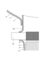
- FIG. 12 is a schematic cross-sectional view for explaining welding between a manifold and a case that houses a heater.
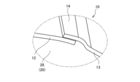
- 13A is an enlarged perspective view of section XIIIA in FIG. 2.
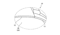
- FIG. FIG. 13B is an enlarged perspective view illustrating a modification of FIG. 13A.
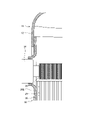
- FIG. 14 is a front view explaining a modification of the manifold.
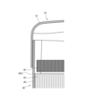
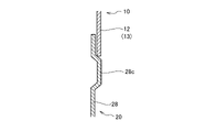
- FIG. 15A is a diagram illustrating a modification of the joint between the manifold and the case that houses the heater.
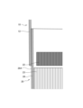
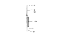
- FIG. 15B is a diagram illustrating another modification of the joint between the manifold and the case that houses the heater.
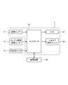
- FIG. 16 is a control block diagram of the exhaust gas treatment device.
- FIG. 17 is a flow chart of secondary air supply control at engine start-up.
- FIG. 18 is a timing chart for explaining secondary air supply control.
- FIG. 19 is a flowchart of heater control.
- FIG. 20 is a perspective view showing one of modifications of the embodiment of the present invention. 21 is a cross-sectional view taken along line XXI-XXI of FIG. 20.
- FIG. FIG. 22 is a perspective view showing another modification of the embodiment of the invention. 23 is a cross-sectional view taken along line XXIII-XXIII of FIG. 22.
- FIG. 1 An exhaust gas treatment device 1 according to an embodiment of the present invention will be described below with reference to FIGS. 1 to 23.
- FIG. 1 An exhaust gas treatment device 1 according to an embodiment of the present invention will be described below with reference to FIGS. 1 to 23.
- FIG. 1 is a perspective view of an exhaust gas treatment device 1.
- FIG. FIG. 2 is a front view of the exhaust gas treatment device 1.
- FIG. FIG. 3 is a schematic cross-sectional view of the exhaust gas treatment device 1. As shown in FIG.
- the exhaust gas processing device 1 is mounted on a vehicle and processes exhaust gas G discharged from an engine (not shown).
- a structural example of the exhaust gas treatment device 1 as a catalytic converter that is compact and has excellent exhaust gas purification performance is shown.
- the exhaust gas treatment device 1 oxidizes hydrocarbons and carbon monoxide contained in the exhaust gas G into carbon dioxide and moisture, reduces nitrogen oxides, and removes fine particulate matter. , to purify the exhaust gas G.
- the exhaust gas treatment device 1 includes a first flow path member 10 as a manifold, a first case 20, a second case 30, a third case 40, and a second flow path. a member 50; In this embodiment, the first case 20, the second case 30, and the third case 40 correspond to cases.
- the exhaust gas treatment device 1 includes an EHC (Electrically Heated Catalyst) 21, a TWC (Three-Way Catalyst) 25 as a first catalyst carrier, and a second catalyst. GPF (Gasoline Particulate Filter) 41 as a carrier.
- the first flow path member 10 has an inlet-side flange 11, a first member 12, a second member 13, and an overlapping portion .
- the first flow path member 10 has an inlet side opening 10a as an inflow port into which the exhaust gas G flows, and an outlet side opening 10b as an outflow port through which the exhaust gas G flows out.
- a secondary air control unit 80 is provided in the first flow path member 10 .
- the inlet flange 11 is connected to an exhaust outlet of an exhaust turbine (not shown).
- the inlet-side flange 11 is provided so as to protrude from the first flow path member 10 in the radial direction of the first case 20 .
- An inlet-side opening 10 a is provided at the protruding end of the inlet-side flange 11 .
- the inlet-side flange 11 is formed in a cylindrical shape with a smooth curved surface, and the diameter gradually decreases along the flow direction of the exhaust gas G. As shown in FIG. By forming the inlet-side flange 11 into a smooth curved surface, the flow of the exhaust gas G guided to the first flow path member 10 is improved.
- the first member 12 is provided on the inner peripheral side of the exhaust gas G flow.
- the second member 13 is provided on the outer peripheral side of the exhaust gas G flow.
- the first member 12 and the second member 13 overlap at an overlapping portion 14, and the overlapping portion 14 is welded and fixed (hereinafter simply referred to as welding) to be integrated.
- the overlapping portions 14 are provided at positions perpendicular to the traveling direction when the exhaust gas G flowing in from the inlet side opening 10a advances linearly, but the positions of the overlapping portions 14 are appropriately determined.
- the exhaust gas G discharged from the engine and flowing in the first direction P flows from the inlet side opening 10a.
- Exhaust gas G is guided downstream from the outlet side opening 10b so as to flow in a second direction Q that intersects with the first direction P.
- the intersecting is not limited to the orthogonal direction as long as the second direction Q is different from the first direction P.
- the first flow path member 10 changes the traveling direction of the exhaust gas G from the first direction P to the second direction Q. As shown in FIG.
- the first flow path member 10 changes the direction of the exhaust gas G flowing in the first direction P from the radial direction of the first case 20 substantially perpendicularly to the second direction of the central axis direction of the first case 20 . It changes the flow along Q.
- the first flow path member 10 has a curved surface portion 15 that is connected to a part of the first case 20 that is adjacent to the inlet side opening 20a so as to smoothly change the traveling direction of the exhaust gas G.
- the first flow path member 10 forms a straight flow path 17a that allows the exhaust gas G to pass through the inlet-side concave portion 20c along the first direction P and advance linearly, and is upstream of the straight flow path 17a. It has a projecting portion 17 that converts the flow of part of the exhaust gas G from the first direction P to the second direction Q on the side. As a result, the flow direction of the exhaust gas G is changed in front while receiving the exhaust gas G up to the opposite wall portion 26A at the back, so that the flow velocity distribution of the exhaust gas G in the first case 20 can be made uniform. . Further, the protruding portion 17 is formed so as to gradually decrease the passage area along the traveling direction when the exhaust gas G flowing in from the inlet side opening portion 10a advances linearly.
- the electrodes 24 of the EHC 21 can be arranged in the vicinity of the opposing wall portion 26A.
- the electrode arrangement possible range 26E in which the electrodes 24 can be arranged will be described later in detail with reference to FIG.
- the first flow path member 10 has an expansion part 18 that is provided upstream in the flow direction of the exhaust gas G from the projecting part 17 and expands the flow path area of the exhaust gas G. By providing the expanded portion 18, the flow of the exhaust gas G within the first flow path member 10 is improved.
- the secondary air control unit 80 supplies air (secondary air) into the first flow path member 10 when the engine is not operating and the exhaust gas G is not flowing.
- the secondary air control unit 80 is provided on the projecting portion 17 of the first channel member 10 .
- the secondary air control unit 80 supplies (injects) air toward the EHC 21 .
- the secondary air control unit 80 can adjust the flow rate [kg/h] of supplied air. Air supplied by secondary air control unit 80 is heated by EHC 21 and directed to TWC 25 . Thereby, the TWC 25 can be heated even when the exhaust gas G is not flowing.
- the first case 20 is cylindrical. As shown in FIG. 3, the first case 20 has an inlet side opening 20a into which the exhaust gas G flows (receives the exhaust gas G from the first flow path member 10) and an outlet side opening through which the exhaust gas G flows out. 20b and . The upstream end of the first case 20 is inserted into the inner circumference of the outlet-side opening 10b of the first channel member 10 . The first case 20 is welded to the first channel member 10 . A temperature sensor 71 is provided in the first case 20 .
- the first case 20 has a cylindrical upstream cylindrical portion 28 and a cylindrical downstream cylindrical portion 29 .
- the downstream end of the upstream cylindrical portion 28 is inserted into and welded to the upstream end of the downstream cylindrical portion 29 .
- the EHC 21 is accommodated in the upstream cylindrical portion 28 .
- a TWC 25 is accommodated in the downstream cylindrical portion 29 .
- the EHC 21 is provided upstream of the TWC 25 in the flow direction of the exhaust gas G, and heats the exhaust gas G that flows in the second direction Q from the first flow path member 10 and is guided to the TWC 25 .
- the EHC 21 has a heater 22 , an electrode support 23 and an electrode 24 .
- the heater 22 generates heat due to the current applied to the electrode 24 .
- the heater 22 is, for example, a spiral electric heater.
- the heater 22 is made of metal.
- the heater 22 is held within the first case 20 (the upstream cylindrical portion 28).
- the electrode support 23 is located upstream of the TWC 25 .
- the electrode support 23 is made of a honeycomb structure that supports the heater 22 and the electrodes 24 .
- the outer peripheral surface of the electrode support 23 is held inside the first case 20 (the upstream cylindrical portion 28).
- the electrode 24 is provided so as to protrude from the heater 22 toward the outside of the first case 20 (upstream cylindrical portion 28) in a direction intersecting the second direction Q (here, the radial direction of the first case 20). Electric power is supplied to the heater 22 from the electrode 24 .
- a plurality of pins are provided between the heater 22 and the electrode support 23 to maintain the gap between the heater 22 and the electrode support 23 and to hold the heater 22 and the electrode 24 .
- a plurality of pins are provided between the heater 22 and the electrode support 23 so as to be inserted into the heater 22 and the electrode support 23 respectively.
- the temperature of the exhaust gas G flowing in the first case 20 is increased from 200 to 200 by applying current to the heater 22 through the electrode 24 at the time of cold start (during cold start) when the engine is started. It is heated to 300[° C.], and the heated exhaust gas G heats the TWC 25 . Thereby, the catalyst component of the TWC 25 can be brought to the activation temperature in a short time. As described above, in the exhaust gas treatment device 1, the catalytic component of the TWC 25 can be activated in a short period of time, so that the purification performance at the start of the engine can be improved.
- the EHC 21 may be of a type in which a conductive carrier carrying a catalyst is energized to raise the temperature.
- the EHC 21 corresponds to the first catalyst carrier.
- the first case 20 is deeply inserted into the first flow path member 10 in order to reduce the size of the exhaust gas treatment device 1 .
- the first case 20 is inserted to a position where the inlet-side opening 20 a faces the inlet-side opening 10 a serving as the inlet of the first flow path member 10 . That is, the EHC 21 enters the first flow path member 10, and the distance from the inlet side opening 10a is short. Therefore, as shown in FIG. 3, the first case 20 is formed with an inlet-side concave portion 20c so as not to block the flow of the exhaust gas G flowing in from the inlet-side opening 10a.
- the inlet-side recess 20c allows the exhaust gas G flowing from the inlet-side opening 10a to pass therethrough. According to such a configuration, the size reduction of the exhaust gas treatment device 1 is achieved, and the obstruction of the flow of the exhaust gas accompanying this is suppressed. As shown in FIGS. 3, 20, and 21, this inlet-side concave portion 20c must be formed at least in a portion through which the exhaust gas G flowing in the first direction P passes. In addition, as shown in FIG.22 and FIG.23, you may form including the circumference
- the first flow path member 10 is provided with a substantially semicircular recess 16 at a position where the electrode 24 is provided so as to avoid the electrode 24 .
- the concave portion 16 is formed larger than the external shape of the electrode 24 in order to suppress the influence of welding heat on the electrode 24 when the first flow path member 10 and the first case 20 are welded. Therefore, the electrode 24 can be arranged only in a portion where the overlapping length between the first flow path member 10 and the first case 20 is equal to or greater than a predetermined length. The arrangement of the electrodes 24 will be described in detail later with reference to FIGS. 4 to 11. FIG.
- the TWC 25 purifies the exhaust gas G flowing in the second direction Q, into which the exhaust gas G guided from the outlet side opening 10b of the first flow path member 10 flows.
- the TWC 25 is supported by the downstream cylindrical portion 29 via a cylindrical inner case 25a that covers the outer periphery.
- the temperature sensor 71 is inserted in the space between the EHC 21 and the TWC 25.
- the temperature sensor 71 detects the temperature [° C.] of the exhaust gas G heated by the EHC 21 and guided to the TWC 25 . That is, the temperature of the exhaust gas G detected by the temperature sensor 71 is substantially equivalent to the temperature of the TWC 25 .
- the second case 30 has a first member 31, a second member 32, and an overlapping portion 33. As shown in FIG. 3, the second case 30 has an inlet-side opening 30a into which the exhaust gas G flows and an outlet-side opening 30b into which the exhaust gas G flows out.
- the second case 30 is provided with an air-fuel ratio sensor 35 as a sensor.
- the exhaust gas G that passes through the TWC 25 and flows in the second direction Q flows from the inlet side opening 30a.
- Exhaust gas G is guided downstream from the outlet side opening 30b so as to flow in a third direction R that intersects with the second direction Q.
- the second case 30 changes the traveling direction of the exhaust gas G from the second direction Q to the third direction R.
- the second case 30 bends the exhaust gas G flowing in the second direction Q in the central axis direction of the first case 20 by approximately 100° to change the direction of the exhaust gas G in the third direction Q in the central axis direction of the third case 40 . It changes the flow along the direction R.
- the first member 31 is provided on the inner peripheral side of the exhaust gas G flow.
- the second member 32 is provided on the outer peripheral side of the exhaust gas G flow.
- the first member 31 and the second member 32 are overlapped at an overlapping portion 33, and the overlapping portion 33 is welded to be integrated.
- the air-fuel ratio sensor 35 has a measuring section 34 that measures the exhaust gas G.
- An air-fuel ratio sensor 35 measures the exhaust gas G that has passed through the TWC 25 .
- the air-fuel ratio sensor 35 has a rod-shaped member, and a measuring section 34 is provided on the tip surface thereof.
- a body portion of the air-fuel ratio sensor 35 is attached to the second member 32 from the outside of the second case 30 so that the measuring portion 34 is positioned on the flow path between the TWC 25 and the GPF 41 .
- the air-fuel ratio sensor 35 attached to the second case 30 is on the flow path between the TWC 25 and the GPF 41, and along the shape of the inner wall surface of the second case 30, the flow velocity of the exhaust gas G is high. A region is formed, and the measuring section 34 is positioned at a position where the flow velocity of the exhaust gas G is faster than the others.
- the second case 30 is provided between the outer peripheral surface of the TWC 25 and the inner peripheral surface of the second case 30, and is formed with an outer peripheral flow path 36 covering the outer periphery of the TWC 25 and the second case 30 protruding inward.
- a branching portion 37 that branches the exhaust gas G that has passed through the GPF 41 and the outer peripheral passage 36 so as to guide it to each of the GPF 41 and the outer peripheral passage 36, and a guide portion 38 that guides the remaining exhaust gas G branched by the branching portion 37 to the outer peripheral passage 36. have.
- the branch portion 37 is formed in a shape in which a part of the pipe wall on the outside in the flow direction of the exhaust gas G in the second case 30 protrudes in the inner diameter direction.
- the guide portion 38 has an inclined portion 38a inclined at a predetermined angle downstream in the second direction Q from the branch portion 37 with respect to a plane orthogonal to the second direction Q, and guides the exhaust gas G that has passed through the inclined portion 38a to the outer peripheral flow. and a curved portion 38b that leads into the channel 36.
- the inclined portion 38a is formed in a substantially planar shape.
- the inclined portion 38a gently guides the exhaust gas G branched by the branching portion 37 to the curved portion 38b and guides it along the inner wall surface of the second case 30 to the outer peripheral flow path 36 .
- the exhaust gas G can be smoothly guided to the outer peripheral flow path 36 without obstructing the flow of the exhaust gas G passing through the TWC 25 toward the branch portion 37 .
- the third case 40 is cylindrical. As shown in FIG. 3, the third case 40 has an inlet-side opening 40a into which the exhaust gas G flows and an outlet-side opening 40b into which the exhaust gas G flows out. A GPF 41 is accommodated in the third case 40 .
- the GPF 41 purifies the exhaust gas G that has passed through the TWC 25 and flows along the third direction R intersecting the second direction Q.
- GPF41 is supported by the 3rd case 40 via the cylindrical inner case 41a which covers an outer periphery.
- the second channel member 50 has an outlet-side flange 51, a first member 52, a second member 53, and an overlapping portion 54.
- the second flow path member 50 has an inlet-side opening 50a (see FIG. 3) into which the exhaust gas G flows, and an outlet-side opening 50b into which the exhaust gas G flows out.
- the outlet side flange 51 is connected to an exhaust pipe (not shown) that guides the exhaust gas G to the outside.
- the outlet side flange 51 is provided so as to protrude from the second flow path member 50 in the radial direction of the third case 40 .
- An outlet-side opening 50 b is provided at the protruding end of the outlet-side flange 51 .
- the first member 52 is provided on the inner peripheral side of the exhaust gas G flow.
- the second member 53 is provided on the outer peripheral side of the exhaust gas G flow.
- the first member 52 and the second member 53 overlap at an overlapping portion 54, and the overlapping portion 54 is welded to be integrated.
- the exhaust gas G heated by the EHC 21 is led to the TWC 25, where the contained hydrocarbons and carbon monoxide are oxidized and decomposed into carbon dioxide and moisture, and nitrogen oxides are reduced.
- the exhaust gas G that has passed through the TWC 25 flows directly toward the upstream end face of the GPF 41 and flows toward the outer peripheral flow path 36 through the guide portion 38 by the branch portion 37 formed on the inner wall surface of the second case 30 . , is divided into
- the flow directly toward the upstream end surface of the GPF 41 forms the main stream of the exhaust gas G, is turned by approximately 100° by the branch portion 37, and flows directly into the upstream end surface of the GPF 41 without going around the outer peripheral flow path 36. .
- the exhaust gas G that has flowed through the guide portion 38 into the outer peripheral passage 36 flows along the outer peripheral surface of the TWC 25 toward the upstream end surface of the GPF 41 .
- the exhaust gas G flowing through the outer peripheral passage 36 heats the TWC 25 from the outer periphery. Since the temperature of the TWC 25 can be raised in a short time immediately after the engine is started by guiding the exhaust gas G to the outer peripheral passage 36 in this way, the TWC 25 can be activated. In particular, since the downstream portion where the temperature of the TWC 25 does not rise can be heated from the outer periphery, the time required for activating the TWC 25 can be shortened.
- the double tube structure composed of the first case 20 and the second case 30 effectively prevents heat from escaping to the outside of the second case 30, and the TWC 25 is covered with the first case 20. Since the exhaust gas G flowing through the outer peripheral channel 36 does not enter the TWC 25, the flow resistance of the exhaust gas G from the outer peripheral channel 36 toward the GPF 41 can be reduced. Further, since the exhaust gas G flowing through the outer peripheral passage 36 does not enter the TWC 25, the flow of the exhaust gas G flowing in the second direction Q within the TWC 25 is prevented from being obstructed.
- the exhaust gas G that has passed through the outer peripheral flow path 36 merges with the flow that is branched by the branch portion 37 and goes directly to the upstream end face of the GPF 41, flows in the third direction R, and flows into the GPF 41. .
- Fine particulate matter is removed from the exhaust gas G that has flowed into the GPF 41, and the exhaust gas G is discharged through the second flow path member 50 to the exhaust pipe.
- FIG. 4 is a conceptual diagram illustrating the electrode dispositionable range 26E when the EHC 21 is viewed in the second direction Q, and is a diagram corresponding to the IV-IV cross section of FIG.
- the electrode 24 faces the inlet-side opening 10a when viewed in the second direction Q in the first case 20, and the exhaust gas G flowing in from the inlet-side opening 10a travels linearly. It is arranged in a region between the opposing wall portion 26A that collides with the case and the overlapping portion forming portion 26D where the overlapping portion 14 is provided.
- the first member 12 and the second member 13 are overlapped and joined. Although the reason will be described later, it is desirable to dispose the electrode 24 in the region between the opposing wall portion 26A and the overlapping portion forming portion 26D.
- the electrode 24 is arranged in a region of the first case 20 excluding the inlet forming portion 26B that overlaps the inlet-side opening 10a when viewed in the second direction Q.
- the inlet forming portion 26B is a region facing the opposing wall portion 26A in the flow direction of the exhaust gas G (first direction P).
- the electrodes 24 are arranged in a region of the first case 20 excluding the curved surface overlapping portion 26C that overlaps with the curved surface portion 15 .
- the curved overlapping portion 26C is a region that is continuous with both ends of the inlet forming portion 26B when viewed in the second direction Q. As shown in FIG.
- the curved overlapped portion 26C may be formed on one side of the inlet forming portion 26B. In some cases, it is formed only at the ends.
- the electrode 24 is arranged in the inlet forming portion 26B or the curved overlapping portion 26C, the exhaust gas G flowing into the first flow path member 10 does not directly hit the electrode 24. Therefore, it is possible to prevent the exhaust gas G from overheating the electrode 24 for supplying power to the heater 22 .
- the electrode 24 needs to be placed away from the first channel member 10 so that the electrode 24 does not interfere with the inlet forming portion 26B or the curved overlapping portion 26C. Further, when the electrode 24 is arranged in the inlet forming portion 26B, the distance between the exhaust turbine and the electrode 24 becomes short, and the temperature of the exhaust turbine may cause the electrode 24 to overheat.
- the electrode 24 is arranged in a region excluding not only the facing wall portion 26A but also the inlet forming portion 26B and the curved overlapping portion 26C. electrode 24 can be placed in the Therefore, it is possible to prevent the exhaust gas treatment device 1 from increasing in size. Also, it is possible to prevent the electrode 24 from overheating due to the temperature of the exhaust turbine.
- the electrode dispositionable range 26E is a region excluding the opposing wall portion 26A when only overheating due to the exhaust gas G is considered.
- the electrode dispositionable range 26E is a region excluding the facing wall portion 26A, the inlet forming portion 26B, and the curved overlapping portion 26C when considering overheating by the exhaust turbine and downsizing of the exhaust gas treatment device 1. is desirable.
- FIG. 5 is a perspective view illustrating the first flow path member 10 and the first case 20 that accommodates the EHC 21.
- FIG. 6 is a sectional view taken along line VI-VI in FIG. 5.
- FIG. 7 is a cross-sectional view taken along line VII-VII in FIG.
- FIG. 8 is a cross-sectional view taken along line VIII-VIII in FIG.
- FIG. 9 is a perspective view of the first flow path member 10 and the first case 20 that houses the EHC 21, viewed from an angle different from that of FIG. 10 is a cross-sectional view taken along the line XX in FIG. 9.
- FIG. 11 is a cross-sectional view taken along line XI-XI in FIG. 9.
- FIG. 9 is a cross-sectional view taken along line XI-XI in FIG. 9.
- the VI-VI cross section is the cross section at the curved overlapping portion 26C
- the VII-VII cross section is the cross section at the inlet forming portion 26B
- the VIII-VIII cross section is the opposite of VI-VI. It is a cross section at the curved overlapping portion 26C on the side.
- the length of overlap between the first flow path member 10 and the first case 20 is small in the curved overlapping portion 26C. Therefore, in order to dispose the electrode 24 at this position, it is necessary to separate the electrode 24 from the first flow path member 10 so as to secure a welding margin. Therefore, it is not desirable to dispose the electrode 24 at this position because the exhaust gas treatment device 1 may become large.
- the overlapping length refers to the length of the portion where the first flow path member 10 and the first case 20 are adjacent to each other and face each other (overlapping).
- the first case 20 is provided with a plug 24a that closes the hole for providing the electrode. Since the plug 24a is not affected by overheating, when the plug 24a is provided, it is not necessary to provide a large recess 16 as in the case where the electrode 24 is provided. Therefore, although it is permissible to provide the plug 24a in the curved surface overlapping portion 26C, it is not desirable to provide the electrode 24 thereon.
- the overlapping length between the first flow path member 10 and the first case 20 is even smaller than in the curved surface overlapping portion 26C. Therefore, in order to dispose the electrode 24 at this position, it is necessary to separate the electrode 24 from the first flow path member 10 by a large distance so as to secure a welding allowance. Therefore, it is not desirable to dispose the electrode 24 at this position because the exhaust gas treatment device 1 may become large.
- the XX cross section is the cross section at the opposing wall portion 26A
- the XI-XI cross section is the cross section at the electrode dispositionable range 26E.
- the overlapping length between the first flow path member 10 and the first case 20 is sufficiently large.
- the exhaust gas G flowing from the inlet side opening 10a advances linearly, it collides with the opposing wall portion 26A. Therefore, the exhaust gas G flowing into the first flow path member 10 from the engine directly hits the electrode 24 . Therefore, since the electrode 24 may be overheated by the exhaust gas G, it is not desirable to arrange the electrode 24 at this position.
- the overlapping length between the first flow path member 10 and the first case 20 is sufficiently large in the electrode arrangement possible range 26E. That is, since the welding allowance between the first flow path member 10 and the first case 20 is large, welding can be performed while avoiding the electrode 24 .
- the exhaust gas G flowing from the inlet side opening 10a advances linearly, it does not collide with the electrode arrangement possible range 26E. That is, the exhaust gas G flowing into the first flow path member 10 from the engine does not hit the electrode 24 at the highest flow velocity. Therefore, the electrodes 24 are not likely to be overheated by the exhaust gas G, and the exhaust gas treatment device 1 is not likely to become large.
- JP2020-143662A cited as the background art, the exhaust gas entering from the inlet hits the wall of the inclined surface and changes its flow direction before reaching the farthest point in the flow direction. That is, the heat load at the farthest wall position (the facing wall portion 26A in this embodiment) is not as large as in this embodiment. In other words, in this embodiment, as a result of correcting the bias of the flow velocity distribution in the heater 22 (or the TWC 25), it can be said that a more appropriate position of the electrode 24 was specified as compared with JP2020-143662A.
- FIG. 12 is a schematic cross-sectional view illustrating welding of the first flow path member 10 and the first case 20.
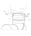
- FIG. 13A is an enlarged perspective view of section XIIIA in FIG. 2.
- FIG. 13B is an enlarged perspective view illustrating a modification of FIG. 13A.
- FIG. 14 is a front view for explaining a modification of the first channel member 10.
- FIG. 15A is a diagram illustrating a modification of the joint portion between the first flow path member 10 and the first case 20.
- FIG. FIG. 15B is a diagram illustrating another modification of the joint portion between the first flow path member 10 and the first case 20.
- the first case 20 is inserted into the inner circumference of the first flow path member 10 and the torch 60 Welding is performed using to form a welded portion 61 over the entire circumference.
- the spatter S generated when welding is performed using the torch 60 passes through the minute gap between the first flow path member 10 and the first case 20 and scatters to the inner periphery of the first flow path member 10. I have something to do. Since the heater 22 is made of metal, the heater 22 may be short-circuited if the spatter S scatters and adheres to the heater 22 .
- the first case 20 is inserted into the inner circumference of the first channel member 10 . That is, the first flow path member 10 overlaps the outer circumference of the first case 20 . Therefore, the spatter S scatters along the inner circumference of the first flow path member 10 in a direction away from the heater 22 and adheres to the inner circumference of the first flow path member 10 . Therefore, by overlapping the first flow path member 10 on the outer periphery of the first case 20, it is possible to prevent the spatters S from scattering and sticking to the heater 22.
- the first flow path member 10 has a divided structure of the first member 12 and the second member 13 , which are welded together at the overlapping portion 14 . Therefore, the degree of freedom of the shape of the first flow path member 10 is high compared to the case where the first flow path member 10 has an integral structure.
- the time for the spatters S to pass through the gap is lengthened, and the heater 22 It can be cooled to the extent that it does not stick to the In the examples shown in FIGS. 22 and 23, the overlapping length of the overlapping portion 14 is made longer than the overlapping length of the location where the entrance-side concave portion 20c is arranged.
- the arrangement of the electrode 24 below the overlapping portion 14 in the drawing is avoided for the following reason. If the electrodes were to be provided at this position, it would be difficult to secure the overlapping length. An attempt to secure the overlapping length leads to an increase in the size of the apparatus. Furthermore, the gaps caused by the overlapped portion 14 make it easier for the spatters S to scatter. For this reason, the arrangement of the electrode 24 below the overlapping portion 14 in the figure is avoided.
- the overlapping portion 14 has a structure in which the end of the second member 13 is enlarged and the end of the second member 13 overlaps the outer circumference of the first member 12 .
- the end of the first member 12 and the end of the second member 13 may be butt welded without providing the overlapping portion 14 . In this case, since a minute gap is not formed at the tip of the first member 12, scattering of the spatters S can be further prevented.
- the first channel member 10 may have a bowl-shaped integrated structure.
- the first flow path member 10 can be press-molded, so the manufacturability of the first flow path member 10 can be improved.
- the upstream cylindrical portion 28 of the first case 20 may be provided with an enlarged diameter portion 28c formed over the entire circumference.
- the downstream end portion of the first flow path member 10 may be provided with an enlarged diameter portion 10c formed over the entire circumference.
- FIG. 16 is a control block diagram of the exhaust gas treatment device 1.
- FIG. 17 is a flow chart of secondary air supply control at engine start-up.
- FIG. 18 is a timing chart for explaining secondary air supply control.
- the exhaust gas treatment device 1 has a controller 70.
- the engine is also provided with an engine rotation speed sensor 72 that detects the rotation speed [rpm] of the engine.
- the controller 70 is composed of a microcomputer equipped with a central processing unit (CPU), read-only memory (ROM), random access memory (RAM), and an input/output interface (I/O interface).
- the controller 70 performs various processes by reading and executing programs stored in the ROM by the CPU.
- the controller 70 can also be composed of a plurality of microcomputers.
- the controller 70 and an ECU (engine control unit) may be integrated into one controller.
- the controller 70 determines the operating state of the EHC 21 based on signals from the temperature sensor 71, the engine rotation speed sensor 72, the outside air temperature sensor 73, etc., and the signal corresponding to the SOC (State Of Charge) from the power storage device 90. It controls the operating state of the secondary air control unit 80, the charge/discharge state of the power storage device 90, and the like.
- SOC State Of Charge
- the secondary air supply control flow shown in FIG. 17 is executed by the controller 70 .
- step S11 the controller 70 determines whether or not the condition for starting the secondary air supply control is satisfied.
- This starting condition is established by detecting any of the following, for example, together with the fact that the engine is not started.
- (1) The door of the driver's seat is opened and the door sensor (not shown) is switched from off to on.
- the driver is seated in the driver's seat, and the weight detection sensor (not shown) detects the driver.
- (3) The driver wears the seat belt and the seat belt sensor (not shown) is switched from off to on.
- the driver grips the steering wheel, and a capacitive sensor (not shown) provided on the steering wheel detects that the driver's hand has touched the steering wheel.
- (5) Detecting radio waves from an electronic key (not shown) and detecting that the user carrying the electronic key has approached the vehicle.
- step S11 If it is determined in step S11 that the starting condition is satisfied, the process proceeds to step S12. On the other hand, if it is determined in step S11 that the starting condition is not satisfied, the process of step S11 is repeated until the starting condition is satisfied.
- step S12 the controller 70 turns on the EHC 21.
- step S13 the controller 70 causes the secondary air control unit 80 to supply (inject) air.
- the secondary air control unit 80 since the secondary air control unit 80 is supplying air while the EHC 21 is on, the air is heated by the EHC 21 and the TWC 25 is heated by the heated air.
- step S14 it is determined whether or not the engine has started. If it is determined in step S14 that the engine has started, the process proceeds to step S15. On the other hand, if it is determined in step S14 that the engine has not started, the process of step S14 is repeated until the engine starts.
- step S15 the controller 70 stops the supply of air from the secondary air control unit 80 because the engine is started and the exhaust gas G is supplied to the exhaust gas treatment device 1.
- step S16 it is determined whether or not a predetermined time has passed.
- the predetermined time is set to the time from when the engine is started until the temperature of the exhaust gas G rises to 200 to 300 [° C.]. If it is determined in step S16 that the predetermined time has passed, the process proceeds to step S17. On the other hand, if it is determined in step S16 that the predetermined time has not passed, the process of step S16 is repeated until the predetermined time has passed.
- step S17 the controller 70 turns off the EHC 21 because the temperature of the engine exhaust gas G has risen to 200-300 [°C].
- the horizontal axis is the time t [sec]
- the vertical axis is the temperature of the TWC 25 [°C]
- the flow rate of the secondary air [kg/h]
- vehicle speed [km/h].
- the temperature T1 is the temperature at which the catalyst of the TWC 25 is activated, and is, for example, 200 to 300 [°C].
- the temperature T2 is the upper limit of the usable temperature of the TWC 25 .
- the controller 70 determines that the condition for starting the secondary air supply control is met, turns on the EHC 21, and causes the secondary air control unit 80 to start supplying air.
- the supply of air by the secondary air control unit 80 may be started after a delay until time t1. That is, after the EHC 21 is turned on, the supply of air by the secondary air control unit 80 may be started after waiting until the temperature of the EHC 21 rises.
- the engine starts based on the engine start request. Since the exhaust gas G is supplied to the exhaust gas treatment device 1 when the engine starts, the controller 70 stops the supply of air from the secondary air control unit 80 . At this time, the temperature T of the TWC 25 has reached the temperature T1, but the heating of the exhaust gas G by the EHC 21 is continued.
- the controller 70 turns off the EHC 21. Also, at time t4, the engine stops.
- the low-temperature exhaust gas G remaining between the engine cylinder (not shown) and the exhaust gas treatment device 1 flows into the exhaust gas treatment device 1 .
- the exhaust gas G discharged from the cylinder may also be at a low temperature. Therefore, the temperature of the TWC 25 may decrease due to the low-temperature exhaust gas G.
- the heating of the exhaust gas G by the EHC 21 continues until the predetermined time elapses even after the engine is started. Therefore, the low-temperature exhaust gas G is heated by the EHC 21 and guided to the TWC 25 . Therefore, it is possible to prevent the temperature of the TWC 25 from dropping.
- control of the EHC 21 will be described with reference to FIG. 19 .
- the control flow of the EHC 21 shown in FIG. 19 is executed by the controller 70 .
- step S10 the controller 70 detects pre-start conditions for the engine.
- the pre-start conditions of the engine are, for example, the outside air temperature detected by the outside air temperature sensor 73, the SOC of the power storage device 90 estimated based on the signal sent from the power storage device 90, and the like.
- step S11 the controller 70 determines whether or not the condition for starting the EHC 21 is satisfied. Since this starting condition is the same as that of step S11 in FIG. 17, the explanation is omitted here.
- step S11 If it is determined in step S11 that the starting condition is satisfied, the process proceeds to step S12. On the other hand, when it is determined in step S11 that the starting condition is not satisfied, the processing of steps S10 and S11 is repeated until the starting condition is satisfied.
- step S12 the controller 70 turns on the EHC 21.
- step S23 the controller 70 determines whether the engine has been restarted. Whether or not the engine has restarted is determined based on the fact that the engine was started in a state in which the engine was not completely cooled (a state in which the water and oil temperatures were not completely lowered). If it is determined in step S23 that the engine has restarted, the process proceeds to step S27. On the other hand, when it is determined in step S23 that the engine has not restarted, the process proceeds to step S24.
- step S24 the controller 70 determines whether the outside air temperature is 0 [°C] or higher. If it is determined in step S24 that the outside air temperature is 0[°C] or higher, the process proceeds to step S25. On the other hand, if it is determined in step S24 that the outside temperature is not 0[°C] or above, that is, if the outside temperature is less than 0[°C], the process proceeds to step S27.
- step S25 the controller 70 determines whether the SOC of the power storage device 90 is 50[%] or more. When it is determined in step S25 that the SOC of power storage device 90 is 50[%] or more, the process proceeds to step S28. On the other hand, if it is determined in step S25 that the SOC of power storage device 90 is not 50[%] or more, ie, that the SOC of power storage device 90 is less than 50[%], the process proceeds to step S27.
- step S26 it is determined whether or not the activation of the TWC 25 has been completed. If it is determined in step S26 that the activation of the TWC 25 has been completed, the process proceeds to step S17. On the other hand, if it is determined in step S26 that the activation of the TWC 25 has not been completed, the process of step S26 is repeated until the activation of the TWC 25 is completed. The state in which the EHC 21 is operated until the activation of the TWC 25 is completed corresponds to the first operating state.
- step S17 the controller 70 turns off the EHC 21.
- step S23 if it is determined in step S23 that the engine has restarted, if it is determined in step S24 that the outside temperature is not 0 [° C.] or less, and in step S25 the SOC of power storage device 90 is 50 [%]. ] In step S27 to which the transition is made when it is determined that the activity is not above 50[%], it is determined whether or not the activity of the EHCF 21 is 50[%] or above.
- step S27 If it is determined in step S27 that the activity of the TWC 25 has reached 50[%] or more, the process proceeds to step S17, and the controller 70 turns off the EHC 21. On the other hand, if it is determined in step S27 that the activity of the TWC 25 has not reached 50[%], the process of step S27 is repeated until the activity of the TWC 25 reaches 50[%]. The state in which the EHC 21 is operated until the activity of the TWC 25 reaches 50[%] corresponds to the second operating state.
- the controller 70 switches the EHC 21 between multiple operating states based on the outside air temperature and the SOC of the power storage device 90 .
- an electric power train (not shown) such as an electric motor that drives the vehicle, and to suppress the amount of carbon dioxide emissions.
- controller 70 when the outside air temperature is 0 [° C.] or less and the SOC of power storage device 90 is less than 50 [%] before the engine is started, controller 70 operates in the first operating state. The heater is operated. On the other hand, before the engine is started, the controller 70 determines whether the outside temperature is 0 [° C.] or less and the SOC of the power storage device 90 is 50 [%] or more, or when the outside temperature is higher than 0 [° C.]. Alternatively, when the engine is restarted, the EHC 21 is operated in a second operating state different from the first operating state. In addition, in the first operating state, the controller 70 operates the EHC 21 until the activation of the TWC 25 is more advanced than in the second operating state.
- the power charged in the power storage device 90 is used to operate the EHC 21, thereby activating the TWC 25.
- EHC 21 is operated until the activity of TWC 25 reaches 50% to activate TWC 25.
- TWC 25 can be activated while ensuring the SOC of device 90 .
- the TWC 25 when the outside air temperature is sufficiently high or when the engine is restarted, the TWC 25 is easily activated, so the EHC 21 is operated until the TWC 25 activity reaches 50 [%] to activate the TWC 25. . Thereby, TWC 25 can be activated without consuming the SOC of power storage device 90 more than necessary.
- control method and controller 70 for the exhaust gas treatment device 1 described above are not limited to the configuration of the exhaust gas treatment device 1 . That is, it is sufficient that at least the heater 22 and the TWC 25 are provided, and it can be applied without depending on the structure of the case or the like.
- the vehicle exhaust gas treatment device 1 including the engine and the power storage device 90 that supplies electric power to the electric power train includes the catalyst carrier (TWC 25) that purifies the exhaust gas G, and the exhaust gas to the TWC 25.
- a heater 22 provided upstream in the flow direction of G and receiving power supply from the power storage device 90 to heat the exhaust gas G guided to the TWC 25; 70 operates the heater 22 in a first operating state when the outside temperature is 0° C. or lower and the state of charge (SOC) of the power storage device 90 is 50% or higher before the engine is started; Before starting the engine, if the outside temperature is 0° C.
- the state of charge (SOC) of the power storage device 90 is less than 50%, if the outside temperature is higher than 0° C., or if the engine is restarted In the case, the heater 22 is operated in a second operating state different from the first operating state.
- controller 70 may operate the heater 22 in the first operating state to a state where the activation of the TWC 25 is more advanced than in the second operating state.
- the state of charge (SOC) of the power storage device 90 is output from the state of charge estimation device (not shown) based on the detection value of the current sensor (not shown), directly or indirectly Input to the controller 70 .
- SOC state of charge
- the outside air temperature is also directly or indirectly output to the controller 70 by a temperature sensor (not shown).
- JP2020-143662A mentioned above discloses a catalytic converter provided with a heater upstream of a catalyst that purifies exhaust gas, but does not disclose control of the heater.
- the exhaust gas treatment device 1 including the controller 70 described above can extend the traveling distance of an electric power train such as an electric motor that drives the vehicle, and can reduce the amount of carbon dioxide emissions.
Landscapes
- Engineering & Computer Science (AREA)
- Chemical & Material Sciences (AREA)
- Chemical Kinetics & Catalysis (AREA)
- Combustion & Propulsion (AREA)
- Mechanical Engineering (AREA)
- General Engineering & Computer Science (AREA)
- Health & Medical Sciences (AREA)
- Toxicology (AREA)
- Biomedical Technology (AREA)
- Environmental & Geological Engineering (AREA)
- Analytical Chemistry (AREA)
- General Chemical & Material Sciences (AREA)
- Oil, Petroleum & Natural Gas (AREA)
- Exhaust Gas After Treatment (AREA)
- Exhaust Silencers (AREA)
Abstract
Description
(1)運転席のドアが開き、ドアセンサ(図示省略)がオフからオンに切り換わったこと。
(2)運転者が運転席に着座し、体重検知センサ(図示省略)が運転者を検知したこと。
(3)運転者がシートベルトを装着し、シートベルトセンサ(図示省略)がオフからオンに切り換わったこと。
(4)運転者がステアリングを握り、ステアリングに設けられる静電容量センサ(図示省略)が運転者の手が触れたことを検知したこと。
(5)電子キー(図示省略)の電波を検知し、電子キーを所持した使用者が車両に近接したことを検知したこと。
Claims (6)
- エンジンから排出される排気ガスを処理する排気ガス処理装置であって、
前記エンジンから排出され第1方向に流れる排気ガスが流入する流入口と、前記第1方向と交差する第2方向に流れるように排気ガスを下流に導く流出口と、を有し、前記第1方向から前記第2方向に排気ガスの進行方向を変えるマニホールドと、
前記マニホールドの前記流出口から導かれる排気ガスが流入し、前記第2方向に流れる排気ガスを浄化する第1触媒担体と、
前記第1触媒担体の排気ガスの流れ方向の上流に設けられ、前記マニホールドから流入して前記第1触媒担体に導かれる排気ガスを加熱するヒータと、
前記第1触媒担体と前記ヒータとを収容するケースと、
を備え、
前記ケースの入口側開口部は、前記マニホールドの前記流入口に臨む位置まで、前記マニホールドの前記流出口の内周に挿入されており、
前記入口側開口部には、前記マニホールドの前記流入口から流れる排気ガスを通過させる入口側凹部が形成される、
排気ガス処理装置。 - 請求項1に記載の排気ガス処理装置であって、
前記マニホールドの前記流出口側の端部は、前記ケースに溶接固定され、
前記マニホールドは、排気ガスの流れの内周側に設けられる第1部材と、排気ガスの流れの外周側に設けられる第2部材と、前記第1部材と前記第2部材とが重複する重複部分と、を有し、
前記重複部分に対応する位置で前記ケースが前記マニホールドへの挿入された部分の重複長さは、前記入口側凹部が形成された位置で前記ケースが前記マニホールドへの挿入された部分の重複長さよりも長く設定される、
排気ガス処理装置。 - 請求項1に記載の排気ガス処理装置であって、
前記第2方向と交差する方向に前記ヒータから前記ケースの外部に向けて突出して設けられ、前記ヒータに電力を供給するための電極を更に備え、
前記マニホールドは、排気ガスの流れの内周側に設けられる第1部材と、排気ガスの流れの外周側に設けられる第2部材と、前記第1部材と前記第2部材とが重複する重複部分と、を有し、
前記ケースは、前記流入口と対向し前記流入口から流入する排気ガスが前記第1方向に沿って前記入口側凹部を通過して直線的に進行した場合に衝突する対向壁部と、を有し、
前記電極は、前記対向壁部と前記重複部分が設けられる重複部分形成部との間の領域に配置される、
排気ガス処理装置。 - 請求項1から3のいずれか一つに記載の排気ガス処理装置であって、
前記ケースは、排気ガスが前記第1方向に沿って前記入口側凹部を通過して直線的に進行可能な直線流路を形成し、且つ、前記直線流路よりも上流側で一部の排気ガスの流れを前記第1方向から前記第2方向に変換する突出部を有する、
排気ガス処理装置。 - 請求項1から3のいずれか一つに記載の排気ガス処理装置であって、
外気温と蓄電装置の充電状態に基づき、前記ヒータの作動状態を制御するコントローラを更に備え、
前記コントローラは、
前記エンジンの始動前に、外気温が0℃以下であり、かつ前記蓄電装置の充電状態が50%以上である場合には、第1運転状態にて前記ヒータを運転させ、
前記エンジンの始動前に、外気温が0℃以下であり、かつ前記蓄電装置の充電状態が50%未満である場合、外気温が0℃よりも高い場合、若しくは前記エンジンが再始動された場合には、前記第1運転状態とは異なる第2運転状態にて前記ヒータを運転させる、
排気ガス処理装置。 - 請求項5に記載の排気ガス処理装置であって、
前記コントローラは、前記第1運転状態では、前記第2運転状態よりも前記第1触媒担体の活性が進んだ状態まで前記ヒータの運転を実行する、
排気ガス処理装置。
Priority Applications (3)
| Application Number | Priority Date | Filing Date | Title |
|---|---|---|---|
| CN202280004900.6A CN115943250B (zh) | 2021-08-05 | 2022-08-03 | 废气处理装置 |
| US18/009,639 US12025043B1 (en) | 2021-08-05 | 2022-08-03 | Exhaust gas processing device |
| EP22812405.3A EP4382732B1 (en) | 2021-08-05 | 2022-08-03 | Exhaust gas processing device |
Applications Claiming Priority (4)
| Application Number | Priority Date | Filing Date | Title |
|---|---|---|---|
| JP2021129328 | 2021-08-05 | ||
| JP2021-129328 | 2021-08-05 | ||
| JP2021197164A JP7112582B1 (ja) | 2021-08-05 | 2021-12-03 | 排気ガス処理装置及び制御方法 |
| JP2021-197164 | 2021-12-03 |
Publications (1)
| Publication Number | Publication Date |
|---|---|
| WO2023013693A1 true WO2023013693A1 (ja) | 2023-02-09 |
Family
ID=82701525
Family Applications (1)
| Application Number | Title | Priority Date | Filing Date |
|---|---|---|---|
| PCT/JP2022/029838 Ceased WO2023013693A1 (ja) | 2021-08-05 | 2022-08-03 | 排気ガス処理装置 |
Country Status (5)
| Country | Link |
|---|---|
| US (1) | US12025043B1 (ja) |
| EP (1) | EP4382732B1 (ja) |
| JP (2) | JP7112582B1 (ja) |
| CN (1) | CN115943250B (ja) |
| WO (1) | WO2023013693A1 (ja) |
Cited By (1)
| Publication number | Priority date | Publication date | Assignee | Title |
|---|---|---|---|---|
| WO2025174749A1 (en) * | 2024-02-13 | 2025-08-21 | Cummins Emission Solutions Inc. | Aftertreatment system including a heater assembly |
Families Citing this family (1)
| Publication number | Priority date | Publication date | Assignee | Title |
|---|---|---|---|---|
| CN220319655U (zh) * | 2023-12-07 | 2024-01-09 | 上海复志信息科技股份有限公司 | 三元催化器及尾气处理装置 |
Citations (5)
| Publication number | Priority date | Publication date | Assignee | Title |
|---|---|---|---|---|
| JP2011202512A (ja) * | 2010-03-24 | 2011-10-13 | Hino Motors Ltd | 排気浄化装置 |
| JP2015075068A (ja) * | 2013-10-11 | 2015-04-20 | トヨタ自動車株式会社 | 車両の制御装置 |
| JP2020143662A (ja) | 2019-01-09 | 2020-09-10 | マレリ株式会社 | 触媒コンバータ及び電熱触媒用電極カバー |
| JP2021129328A (ja) | 2015-01-15 | 2021-09-02 | 三菱電機株式会社 | 通信システム、基地局および通信端末 |
| JP2021197164A (ja) | 2020-06-12 | 2021-12-27 | 富士通株式会社 | 情報処理装置、情報処理方法及びコンピュータ可読記憶媒体 |
Family Cites Families (18)
| Publication number | Priority date | Publication date | Assignee | Title |
|---|---|---|---|---|
| US3733181A (en) * | 1971-05-14 | 1973-05-15 | Chemical Construction Corp | Catalytic exhaust gas treatment apparatus |
| JPH0693837A (ja) * | 1992-09-16 | 1994-04-05 | Mitsubishi Electric Corp | 電気加熱触媒制御装置 |
| JP2004076587A (ja) * | 2002-08-09 | 2004-03-11 | Toyota Motor Corp | 内燃機関の排気管構造 |
| JP2005273542A (ja) * | 2004-03-24 | 2005-10-06 | Calsonic Kansei Corp | 排気系部材の遮熱板組み付け方法 |
| KR20060115939A (ko) * | 2005-05-07 | 2006-11-13 | (주)네오포텍 | 디젤엔진의 배기정화시스템 및 방법 |
| DE102005002289B4 (de) * | 2005-01-17 | 2007-04-19 | J. Eberspächer GmbH & Co. KG | Abgasbehandlungssystem |
| JP4834041B2 (ja) * | 2008-08-04 | 2011-12-07 | 本田技研工業株式会社 | 排ガス浄化装置 |
| JP2010216366A (ja) | 2009-03-17 | 2010-09-30 | Honda Motor Co Ltd | 排気浄化装置 |
| US8893481B2 (en) * | 2013-01-17 | 2014-11-25 | Komatsu Ltd. | Reductant aqueous solution mixing device and exhaust aftertreatment device provided with the same |
| DE102016213414A1 (de) * | 2016-07-22 | 2018-01-25 | Bayerische Motoren Werke Aktiengesellschaft | Abgasanlage für eine Brennkraftmaschine |
| CN108571368B (zh) * | 2017-03-10 | 2020-06-16 | 马自达汽车株式会社 | 发动机的排气装置 |
| KR102371619B1 (ko) * | 2017-11-29 | 2022-03-07 | 현대자동차주식회사 | 배기가스 후처리장치 |
| JP7103900B2 (ja) | 2018-09-18 | 2022-07-20 | ダイハツ工業株式会社 | 内燃機関の排気ガス浄化装置 |
| JP6814268B1 (ja) | 2019-09-25 | 2021-01-13 | マレリ株式会社 | 排気ガス処理装置 |
| CN113906199B (zh) * | 2019-05-22 | 2023-11-28 | 日产自动车株式会社 | 催化转化器 |
| JP2021076109A (ja) * | 2019-11-08 | 2021-05-20 | 株式会社三五 | 排気ガス処理装置 |
| JP6932231B1 (ja) | 2020-11-30 | 2021-09-08 | マレリ株式会社 | 排気処理装置 |
| JP7071487B2 (ja) * | 2020-12-18 | 2022-05-19 | マレリ株式会社 | 排気ガス処理装置 |
-
2021
- 2021-12-03 JP JP2021197164A patent/JP7112582B1/ja active Active
- 2021-12-03 JP JP2021197181A patent/JP7145307B1/ja active Active
-
2022
- 2022-08-03 EP EP22812405.3A patent/EP4382732B1/en active Active
- 2022-08-03 US US18/009,639 patent/US12025043B1/en active Active
- 2022-08-03 WO PCT/JP2022/029838 patent/WO2023013693A1/ja not_active Ceased
- 2022-08-03 CN CN202280004900.6A patent/CN115943250B/zh active Active
Patent Citations (5)
| Publication number | Priority date | Publication date | Assignee | Title |
|---|---|---|---|---|
| JP2011202512A (ja) * | 2010-03-24 | 2011-10-13 | Hino Motors Ltd | 排気浄化装置 |
| JP2015075068A (ja) * | 2013-10-11 | 2015-04-20 | トヨタ自動車株式会社 | 車両の制御装置 |
| JP2021129328A (ja) | 2015-01-15 | 2021-09-02 | 三菱電機株式会社 | 通信システム、基地局および通信端末 |
| JP2020143662A (ja) | 2019-01-09 | 2020-09-10 | マレリ株式会社 | 触媒コンバータ及び電熱触媒用電極カバー |
| JP2021197164A (ja) | 2020-06-12 | 2021-12-27 | 富士通株式会社 | 情報処理装置、情報処理方法及びコンピュータ可読記憶媒体 |
Non-Patent Citations (1)
| Title |
|---|
| See also references of EP4382732A4 |
Cited By (1)
| Publication number | Priority date | Publication date | Assignee | Title |
|---|---|---|---|---|
| WO2025174749A1 (en) * | 2024-02-13 | 2025-08-21 | Cummins Emission Solutions Inc. | Aftertreatment system including a heater assembly |
Also Published As
| Publication number | Publication date |
|---|---|
| JP7145307B1 (ja) | 2022-09-30 |
| CN115943250B (zh) | 2026-02-27 |
| EP4382732A1 (en) | 2024-06-12 |
| JP7112582B1 (ja) | 2022-08-03 |
| US20240191643A1 (en) | 2024-06-13 |
| EP4382732A4 (en) | 2024-12-11 |
| JP2023024236A (ja) | 2023-02-16 |
| EP4382732B1 (en) | 2026-04-08 |
| US12025043B1 (en) | 2024-07-02 |
| CN115943250A (zh) | 2023-04-07 |
| JP2023024235A (ja) | 2023-02-16 |
Similar Documents
| Publication | Publication Date | Title |
|---|---|---|
| CA2900801C (en) | Dosing and mixing arrangement for use in exhaust aftertreatment | |
| JP5132187B2 (ja) | 排気浄化装置 | |
| WO2023013693A1 (ja) | 排気ガス処理装置 | |
| US8464516B2 (en) | Inlet for exhaust treatment device | |
| TWI384120B (zh) | 機車用四衝程引擎之排氣系統 | |
| WO2009128407A1 (ja) | 内燃機関の排気浄化システム | |
| JP2005299631A (ja) | 自動車排気ガス浄化システム | |
| JP6526213B2 (ja) | 内燃機関の排気ガスを浄化するための排気ガス浄化コンポーネント | |
| JP6079531B2 (ja) | エンジンの排気装置 | |
| JP5333672B2 (ja) | 内燃機関の排気浄化装置 | |
| JP2018044528A (ja) | エンジンの排気浄化装置 | |
| JP2009036150A (ja) | 内燃機関の還元剤添加装置 | |
| JP5878364B2 (ja) | 排気処理装置 | |
| JP6890735B2 (ja) | 排気ガス処理装置 | |
| CN111263849B (zh) | 内燃机的排气净化装置 | |
| WO2014087466A1 (ja) | 内燃機関の排気浄化システム | |
| JP7071487B2 (ja) | 排気ガス処理装置 | |
| JP6814268B1 (ja) | 排気ガス処理装置 | |
| JP4924834B2 (ja) | 内燃機関の排気ガス浄化装置 | |
| JP2011220302A (ja) | 内燃機関の排気装置 | |
| CN113272534A (zh) | 尾气处理装置 | |
| JP4702281B2 (ja) | 内燃機関の触媒装置および排気浄化システム | |
| JP2011021485A (ja) | 自動車用排気浄化装置 | |
| JP2023128908A (ja) | 排気ガス浄化システム及び排気ガス浄化システムの制御装置 | |
| JP2019065783A (ja) | 内燃機関の排気浄化装置 |
Legal Events
| Date | Code | Title | Description |
|---|---|---|---|
| WWE | Wipo information: entry into national phase |
Ref document number: 18009639 Country of ref document: US |
|
| 121 | Ep: the epo has been informed by wipo that ep was designated in this application |
Ref document number: 22812405 Country of ref document: EP Kind code of ref document: A1 |
|
| NENP | Non-entry into the national phase |
Ref country code: DE |
|
| ENP | Entry into the national phase |
Ref document number: 2022812405 Country of ref document: EP Effective date: 20240305 |
|
| WWG | Wipo information: grant in national office |
Ref document number: 2022812405 Country of ref document: EP |