WO2023017640A1 - 撮像装置及び電子機器 - Google Patents
撮像装置及び電子機器 Download PDFInfo
- Publication number
- WO2023017640A1 WO2023017640A1 PCT/JP2022/012067 JP2022012067W WO2023017640A1 WO 2023017640 A1 WO2023017640 A1 WO 2023017640A1 JP 2022012067 W JP2022012067 W JP 2022012067W WO 2023017640 A1 WO2023017640 A1 WO 2023017640A1
- Authority
- WO
- WIPO (PCT)
- Prior art keywords
- gate electrode
- pixel
- imaging device
- diffusion region
- semiconductor substrate
- Prior art date
- Legal status (The legal status is an assumption and is not a legal conclusion. Google has not performed a legal analysis and makes no representation as to the accuracy of the status listed.)
- Ceased
Links
Images





Classifications
-
- H—ELECTRICITY
- H10—SEMICONDUCTOR DEVICES; ELECTRIC SOLID-STATE DEVICES NOT OTHERWISE PROVIDED FOR
- H10F—INORGANIC SEMICONDUCTOR DEVICES SENSITIVE TO INFRARED RADIATION, LIGHT, ELECTROMAGNETIC RADIATION OF SHORTER WAVELENGTH OR CORPUSCULAR RADIATION
- H10F39/00—Integrated devices, or assemblies of multiple devices, comprising at least one element covered by group H10F30/00, e.g. radiation detectors comprising photodiode arrays
- H10F39/80—Constructional details of image sensors
- H10F39/802—Geometry or disposition of elements in pixels, e.g. address-lines or gate electrodes
-
- H—ELECTRICITY
- H10—SEMICONDUCTOR DEVICES; ELECTRIC SOLID-STATE DEVICES NOT OTHERWISE PROVIDED FOR
- H10F—INORGANIC SEMICONDUCTOR DEVICES SENSITIVE TO INFRARED RADIATION, LIGHT, ELECTROMAGNETIC RADIATION OF SHORTER WAVELENGTH OR CORPUSCULAR RADIATION
- H10F39/00—Integrated devices, or assemblies of multiple devices, comprising at least one element covered by group H10F30/00, e.g. radiation detectors comprising photodiode arrays
- H10F39/80—Constructional details of image sensors
- H10F39/803—Pixels having integrated switching, control, storage or amplification elements
- H10F39/8037—Pixels having integrated switching, control, storage or amplification elements the integrated elements comprising a transistor
- H10F39/80373—Pixels having integrated switching, control, storage or amplification elements the integrated elements comprising a transistor characterised by the gate of the transistor
-
- H—ELECTRICITY
- H10—SEMICONDUCTOR DEVICES; ELECTRIC SOLID-STATE DEVICES NOT OTHERWISE PROVIDED FOR
- H10F—INORGANIC SEMICONDUCTOR DEVICES SENSITIVE TO INFRARED RADIATION, LIGHT, ELECTROMAGNETIC RADIATION OF SHORTER WAVELENGTH OR CORPUSCULAR RADIATION
- H10F39/00—Integrated devices, or assemblies of multiple devices, comprising at least one element covered by group H10F30/00, e.g. radiation detectors comprising photodiode arrays
- H10F39/011—Manufacture or treatment of image sensors covered by group H10F39/12
- H10F39/014—Manufacture or treatment of image sensors covered by group H10F39/12 of CMOS image sensors
-
- H—ELECTRICITY
- H10—SEMICONDUCTOR DEVICES; ELECTRIC SOLID-STATE DEVICES NOT OTHERWISE PROVIDED FOR
- H10F—INORGANIC SEMICONDUCTOR DEVICES SENSITIVE TO INFRARED RADIATION, LIGHT, ELECTROMAGNETIC RADIATION OF SHORTER WAVELENGTH OR CORPUSCULAR RADIATION
- H10F39/00—Integrated devices, or assemblies of multiple devices, comprising at least one element covered by group H10F30/00, e.g. radiation detectors comprising photodiode arrays
- H10F39/80—Constructional details of image sensors
- H10F39/807—Pixel isolation structures
-
- H—ELECTRICITY
- H10—SEMICONDUCTOR DEVICES; ELECTRIC SOLID-STATE DEVICES NOT OTHERWISE PROVIDED FOR
- H10F—INORGANIC SEMICONDUCTOR DEVICES SENSITIVE TO INFRARED RADIATION, LIGHT, ELECTROMAGNETIC RADIATION OF SHORTER WAVELENGTH OR CORPUSCULAR RADIATION
- H10F39/00—Integrated devices, or assemblies of multiple devices, comprising at least one element covered by group H10F30/00, e.g. radiation detectors comprising photodiode arrays
- H10F39/80—Constructional details of image sensors
- H10F39/812—Arrangements for transferring the charges in the image sensor perpendicular to the imaging plane, e.g. buried regions used to transfer generated charges to circuitry under the photosensitive region
Definitions
- the present disclosure relates to imaging devices and electronic devices.
- CMOS Complementary Metal-Oxide-Semiconductor
- CMOS image sensors in order to increase the amount of charge that can be stored in the photodiodes that perform photoelectric conversion in the pixel section, charges can be stored in deep regions. can create such potential.
- CMOS image sensors by using a vertical gate electrode inserted into silicon instead of a normal transfer gate, reading is performed by modulating a deep region and applying an electric field.
- a structure employing a plurality of vertical gate electrodes has also been proposed in order to increase the modulation power.
- the width of the transfer gate electrode in the channel length direction is made wider than the diameter of the vertical gate electrode in order to suppress a decrease in transfer efficiency when extracting the charge accumulated in the photodiode. I had to.
- the width of the transfer gate electrode is widened, an electron avalanche may occur due to the strong electric field formed by the proximity of the transfer gate electrode and the floating diffusion region, thereby saturating the amplitude of the pixel signal.
- image quality deterioration such as dots occurs.
- the present disclosure proposes an imaging device and an electronic device capable of suppressing degradation in image quality while suppressing degradation in transfer efficiency.
- an imaging device includes a plurality of pixels arranged in a two-dimensional lattice, each of the pixels being provided on the first surface side of a semiconductor substrate, a photoelectric conversion portion that photoelectrically converts light; a vertical gate electrode provided on the semiconductor substrate so as to approach the photoelectric conversion portion from a second surface opposite to the first surface; and the vertical gate electrode. and the semiconductor substrate; a transfer gate electrode connected to the vertical gate electrode on the second surface of the semiconductor substrate; and a first diffusion region, and the vertical gate electrode has a structure in which a bottom portion on the side of the photoelectric conversion portion is larger in diameter than an upper portion on the side of the transfer gate electrode.
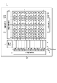
- FIG. 1 is a block diagram showing a schematic configuration example of an imaging device applied to each embodiment of the present disclosure
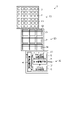
- FIG. FIG. 4 is a diagram for explaining an example of a seat element structure of an imaging device applied to each embodiment of the present disclosure
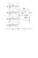
- FIG. 3 is a circuit diagram showing an example of a pixel and a readout circuit shown in FIG. 2
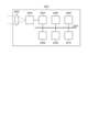
- FIG. 1 is a block diagram showing a configuration example of an imaging device mounted on an electronic device applied to each embodiment of the present disclosure
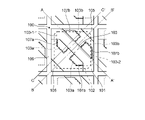
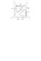
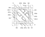
- FIG. 2 is a top view showing a schematic configuration example of a pixel according to the first embodiment
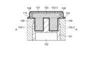
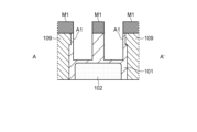
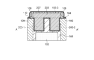
- FIG. FIG. 6 is a vertical cross-sectional view showing a structural example of the A-A′ cross section in FIG. 5;
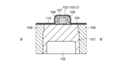
- FIG. 6 is a vertical cross-sectional view showing a structural example of a B-B′ cross section in FIG. 5;
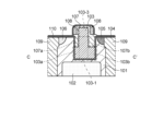
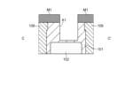
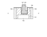
- FIG. 6 is a vertical cross-sectional view showing a structural example of the C-C′ cross section in FIG. 5;
- 1A to 1D are process cross-sectional views showing an example of a manufacturing process of a pixel according to the first embodiment (No. 1);
- FIG. 10 is a process cross-sectional view showing an example of a manufacturing process of the pixel according to the first embodiment (No. 2);
- 3A to 3D are process cross-sectional views showing an example of a manufacturing process of a pixel according to the first embodiment (No.
- 4A to 4C are process cross-sectional views showing an example of a manufacturing process of the pixel according to the first embodiment
- 5A to 5C are process cross-sectional views showing an example of a manufacturing process of the pixel according to the first embodiment (No. 5)
- 6A to 6C are process cross-sectional views showing an example of a manufacturing process of the pixel according to the first embodiment (No. 6)
- 7A to 7C are process cross-sectional views showing an example of a manufacturing process of the pixel according to the first embodiment (No. 7);
- 8A to 8D are process cross-sectional views showing an example of a manufacturing process of the pixel according to the first embodiment (No. 8);
- FIG. 8
- FIG. 13 is a process cross-sectional view showing an example of a manufacturing process of the pixel according to the first embodiment (No. 9);
- FIG. 10 is a top view showing a schematic configuration example of a pixel according to the second embodiment;
- FIG. 19 is a vertical sectional view showing a structural example of the A-A′ section in FIG. 18;
- FIG. 11 is a vertical cross-sectional view showing a schematic configuration example of a pixel according to a third embodiment;
- FIG. 11 is a vertical cross-sectional view showing a schematic configuration example of a pixel according to a fourth embodiment;
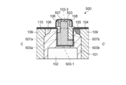
- FIG. 11 is a vertical cross-sectional view showing a schematic configuration example of a pixel according to a fifth embodiment;
- FIG. 11 is a vertical cross-sectional view showing a schematic configuration example of a pixel according to a sixth embodiment
- FIG. 20 is a top view showing a schematic configuration example of a pixel according to the seventh embodiment
- FIG. 20 is a top view showing a schematic configuration example of a pixel according to the eighth embodiment
- FIG. 20 is a top view showing a schematic configuration example of a pixel according to the ninth embodiment
- FIG. 22 is a partial cross-sectional view showing a structural example of a pixel according to the tenth embodiment
- FIG. 22 is a partial cross-sectional view showing a structural example of a pixel according to the eleventh embodiment
- 1 is a block diagram showing an example of a schematic configuration of a vehicle control system;
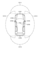
- FIG. 4 is an explanatory diagram showing an example of installation positions of an outside information detection unit and an imaging unit; 1 is a diagram showing an example of a schematic configuration of an endoscopic surgery system; FIG. 3 is a block diagram showing an example of functional configurations of a camera head and a CCU; FIG.
- FIG. 1 is a block diagram showing a schematic configuration example of an imaging device applied to each embodiment of the present disclosure.
- an imaging device 1 includes a pixel array section (so-called imaging area) 3 in which pixels 2 each including a plurality of photoelectric conversion elements are regularly arranged two-dimensionally on a semiconductor substrate ST (for example, a silicon substrate). and a peripheral circuit section.
- the pixel 2 has, for example, a photodiode serving as a photoelectric conversion element and a plurality of pixel transistors (so-called MOS transistors).
- a plurality of pixel transistors can be composed of, for example, three transistors, a transfer transistor, a reset transistor, and an amplification transistor.
- Pixel 2 can also be a shared pixel structure. This pixel-sharing structure is composed of a plurality of photodiodes, a plurality of transfer transistors, one shared floating diffusion, and one shared pixel transistor.
- the peripheral circuit section includes a vertical drive circuit 4, a column signal processing circuit 5, a horizontal drive circuit 6, an output circuit 7, a control circuit 8, and the like.
- the control circuit 8 receives an input clock and data instructing an operation mode, etc., and outputs data such as internal information of the imaging device. That is, the control circuit 8 generates a clock signal and a control signal that serve as a reference for the operation of the vertical driving circuit 4, the column signal processing circuit 5, the horizontal driving circuit 6, etc. based on the vertical synchronizing signal, the horizontal synchronizing signal, and the master clock. do. These signals are input to the vertical drive circuit 4, the column signal processing circuit 5, the horizontal drive circuit 6, and the like.
- the vertical drive circuit 4 is composed of, for example, a shift register, selects a pixel drive wiring, supplies a pulse for driving the pixels to the selected pixel drive wiring, and drives the pixels row by row. That is, the vertical driving circuit 4 sequentially selectively scans the pixels 2 of the pixel array section 3 in the vertical direction row by row, and scans the photoelectric conversion elements of the pixels 2 through vertical signal lines 24, such as photodiodes, according to the amount of received light.
- the column signal processing circuit 5 is supplied with a pixel signal based on the signal charge generated by the above.
- the column signal processing circuit 5 is arranged, for example, for each column of the pixels 2, and performs signal processing such as noise removal on the signals output from the pixels 2 of one row for each pixel column. That is, the column signal processing circuit 5 performs signal processing such as correlated double sampling (CDS) for removing fixed pattern noise unique to the pixel 2, signal amplification, and AD conversion.
- a horizontal selection switch (not shown) is connected between the output stage of the column signal processing circuit 5 and the horizontal signal line HL.
- the horizontal driving circuit 6 is composed of, for example, a shift register, and sequentially outputs horizontal scanning pulses to select each of the column signal processing circuits 5 in turn, and outputs pixel signals from each of the column signal processing circuits 5 to the horizontal signal line. output to HL.
- the output circuit 7 performs signal processing on the signals sequentially supplied from each of the column signal processing circuits 5 through the horizontal signal line HL, and outputs the processed signals. For example, only buffering HL may be performed, or black level adjustment, column variation correction, and various digital signal processing may be performed.
- the input/output terminal I/O exchanges signals with the outside.
- FIG. 2 is a diagram for explaining an example of a seat item structure of an imaging device applied to each embodiment of the present disclosure.
- the imaging device 1 can have a three-dimensional structure configured by bonding together three substrates (first substrate 10, second substrate 20, and third substrate 30). The first substrate 10, the second substrate 20 and the third substrate 30 are laminated in this order.
- the first substrate 10 has a plurality of pixels 2 for performing photoelectric conversion on a semiconductor substrate 11 .
- a plurality of pixels 2 are arranged in a matrix in the pixel array section 3 on the first substrate 10 .
- the second substrate 20 has, on a semiconductor substrate 21 , readout circuits 22 for outputting pixel signals based on charges output from the pixels 2 , one for each of the four pixels 2 .
- the second substrate 20 has a plurality of pixel drive lines 23 extending in the row direction and a plurality of vertical signal lines 24 extending in the column direction.
- the third substrate 30 has a logic circuit 32 for processing pixel signals on a semiconductor substrate 31 .
- the logic circuit 32 has a vertical drive circuit 4, a column signal processing circuit 5, a horizontal drive circuit 6 and a control circuit 8, for example.
- the logic circuit 32 (specifically, the horizontal drive circuit 6) outputs the output voltage Vout for each pixel 2 to the outside.
- a low-resistance region made of silicide such as CoSi 2 or NiSi formed by a salicide (Self-Aligned Silicide) process is formed on the surface of the impurity diffusion region in contact with the source electrode and the drain electrode.
- the vertical drive circuit 4 sequentially selects a plurality of pixels 2 in row units.
- the column signal processing circuit 5 performs, for example, CDS processing on pixel signals output from the pixels 2 in the row selected by the vertical driving circuit 4 .
- the column signal processing circuit 5 extracts the signal level of the pixel signal by performing CDS processing, for example, and holds pixel data corresponding to the amount of light received by each pixel 2 .
- the horizontal driving circuit 6, for example, sequentially outputs the pixel data held in the column signal processing circuit 5 to the outside.
- the control circuit 8 controls driving of each block (the vertical driving circuit 4, the column signal processing circuit 5 and the horizontal driving circuit 6) in the logic circuit 32, for example.
- FIG. 3 shows an example of the pixel 2 and the readout circuit 22.
- “shared” means that the outputs of the four pixels 2 are input to the common readout circuit 22 .
- Each pixel 2 has components common to each other.
- identification numbers (1, 2, 3, 4) are added to the end of the reference numerals of the constituent elements of each pixel 2 in order to distinguish the constituent elements of each pixel 2 from each other.
- an identification number is attached to the end of the reference numerals of the constituent elements of each pixel 2. If not, the identification number at the end of the code for the component of each pixel 2 is omitted.
- Each pixel 2 includes, for example, a photodiode PD, a transfer transistor TR electrically connected to the photodiode PD, and a floating diffusion region that temporarily holds charges output from the photodiode PD via the transfer transistor TR. FD.
- the photodiode PD corresponds to a specific example of the "photoelectric conversion section" of the present disclosure.
- the photodiode PD performs photoelectric conversion to generate charges according to the amount of light received.
- a cathode of the photodiode PD is electrically connected to the source of the transfer transistor TR, and an anode of the photodiode PD is electrically connected to a reference potential line (eg ground).
- a drain of the transfer transistor TR is electrically connected to the floating diffusion region FD, and a gate of the transfer transistor TR is electrically connected to the pixel drive line 23 .
- the transfer transistor TR is, for example, a CMOS transistor.
- the floating diffusion regions FD of each pixel 2 sharing one readout circuit 22 are electrically connected to each other and to the input terminal of the common readout circuit 22 .
- the readout circuit 22 has, for example, a reset transistor RST, a selection transistor SEL, and an amplification transistor AMP. Note that the selection transistor SEL may be omitted if necessary.
- the source of the reset transistor RST (the input terminal of the readout circuit 22) is electrically connected to the floating diffusion region FD, and the drain of the reset transistor RST is electrically connected to the power supply line VDD and the drain of the amplification transistor AMP. .
- a gate of the reset transistor RST is electrically connected to the pixel drive line 23 (see FIG. 2).
- the source of the amplification transistor AMP is electrically connected to the drain of the select transistor SEL, and the gate of the amplification transistor AMP is electrically connected to the source of the reset transistor RST.
- the source of the selection transistor SEL (the output terminal of the readout circuit 22) is electrically connected to the vertical signal line 24, and the gate of the selection transistor SEL is electrically connected to the pixel drive line 23 (see FIG. 2). .
- the imaging device 1 as described above is, for example, an imaging system such as a digital still camera or a digital video camera, a mobile phone with an imaging function, or another device with an imaging function. can be applied to various electronic devices such as
- FIG. 4 is a block diagram showing a configuration example of an imaging device mounted on an electronic device.
- an electronic device 2001 includes an optical system 2002, an imaging device 2003, and a DSP (Digital Signal Processor) 2004. , a recording device 2009, and a power supply system 2010 are connected, and can capture still images and moving images.
- DSP Digital Signal Processor
- the optical system 2002 is configured with one or more lenses, guides the image light (incident light) from the subject to the imaging device 2003, and forms an image on the light receiving surface (sensor unit) of the imaging device 2003.
- the imaging device 2003 As the imaging device 2003, the imaging device 1 having any of the configuration examples described above is applied. Electrons are accumulated in the imaging device 2003 for a certain period of time according to the image formed on the light receiving surface via the optical system 2002 . A signal corresponding to the electrons accumulated in the imaging device 2003 is supplied to the DSP 2004 .
- the DSP 2004 performs various signal processing on the signal from the imaging device 2003 to obtain an image, and temporarily stores the image data in the memory 2008 .
- the image data stored in the memory 2008 is recorded in the recording device 2009 or supplied to the display device 2005 to display the image.
- An operation system 2006 receives various operations by a user and supplies an operation signal to each block of the electronic device 2001 , and a power supply system 2010 supplies electric power necessary for driving each block of the electronic device 2001 .
- the number of layers of the metal layer 58 can be reduced more effectively, and the cost can be reduced. can be planned.
- the pixel 100 may have a configuration corresponding to the pixel 2 provided on the first substrate 10 in the common configuration example described above.
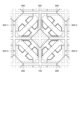
- FIG. 5 is a top view showing a schematic configuration example of a pixel according to this embodiment.
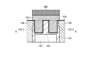
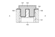
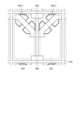
- FIG. 6 is a vertical sectional view showing a structural example of the AA' section in FIG.
- FIG. 7 is a vertical sectional view showing a structural example of the BB' section in FIG.
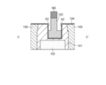
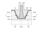
- FIG. 8 is a vertical cross-sectional view showing a structural example of the CC' cross section in FIG.
- one pixel 100 is provided in each pixel region separated in a two-dimensional grid pattern by the pixel separating portion 109 that partitions the semiconductor substrate 101.
- the pixel 100 includes a photoelectric conversion unit 102 provided, for example, on the back surface side (lower surface side in the drawing) of a semiconductor substrate 101, and charges accumulated in the photoelectric conversion unit 102 are transferred to the front surface side (in the drawing) of the semiconductor substrate 101. , upper surface side), a gate insulating film 104 provided between the transfer gate 103 and the semiconductor substrate 101, and one of the four corners of the pixel region in the upper layer of the semiconductor substrate 101.
- a floating diffusion region 105 provided, a ground contact 106 provided at one of the four corners of the pixel region in the upper layer of the semiconductor substrate 101 diagonally opposite to the corner where the floating diffusion region 105 is provided, and at least a transfer and an insulating film 107 provided between the gate 103 and the floating diffusion region 105 and/or the ground contact 106 .
- the transfer gate 103 includes a plurality of vertical gate electrodes 103-1 and 103- protruding from the front surface side of the semiconductor substrate 101 in the substrate thickness direction so that the tip (corresponding to the bottom surface) of the transfer gate 103 is close to the photoelectric conversion unit 102. 2 and a transfer gate electrode 103-3 connecting the plurality of vertical gate electrodes 103-1 and 103-2 on the surface of the semiconductor substrate 101.
- the number of vertical gate electrodes is two and the transfer gate 103 has a ⁇ -shape as a whole is exemplified, but the number of vertical gate electrodes is one. It may be 1 or 3 or more.
- the pixel structure of the pixel 100 including the transfer gate 103 is symmetrical with respect to the line connecting the floating diffusion region 105 and the ground contact 106 as the center line. However, it may be asymmetrical.
- Each of the vertical gate electrodes 103-1 and 103-2 has a diameter approximately equal to the width of the transfer gate electrode 103-3 on the upper side (the side of the transfer gate electrode 103-3), and side) is wider than the upper side. That is, in this example, when the semiconductor substrate 101 is viewed from above, the enlarged-diameter portions 103a and 103b on the bottom side of the vertical gate electrodes 103-1 and 103-2 respectively correspond to the transfer gate electrodes 103 on the semiconductor substrate 101. It protrudes from -3.
- the enlarged diameter portions 103a and 103b may be provided at positions deeper than the depth position of the floating diffusion region 105 and/or the ground contact 106 in the substrate thickness direction. However, it is not limited to this, and various modifications may be made as long as the distance from the transfer gate 103 to the floating diffusion region 105 and/or the ground contact 106 can be secured.
- the vertical gate electrodes 103-1 and 103-2 each have a structure in which the bottom side is wider than the top side, so that the floating diffusion region 105 and/or the ground contact 106 are formed from the transfer gate electrode 103-3. It is possible to increase the area of the surface (bottom surface) of the transfer gate 103 facing the photoelectric conversion unit 102 while ensuring the distance to the transfer gate 103, thereby suppressing the deterioration of image quality due to the formation of a strong electric field and improving the transfer efficiency. It becomes possible to suppress the decrease in
- the widths in the channel length direction of the enlarged diameter portions 103a and 103b in the vertical gate electrodes 103-1 and 103-2 may be the same or different.
- the width of the enlarged diameter portion 103b on the floating diffusion region 105 side may be wider than the width of the enlarged diameter portion 103a on the ground contact 106 side. By doing so, it is possible to further suppress formation of a strong electric field between the transfer gate 103 and the floating diffusion region 105 .
- the channel length direction may be the direction connecting the floating diffusion region 105 and the transfer gate 103 (for example, the ground contact 106 on the extension line).
- an insulating film 107 is provided on each of the vertical gate electrodes 103-1 and 103-2.
- portions of the insulating film 107 that are located on the side surfaces of the vertical gate electrodes 103-1 and 103-2 are also referred to as buried sidewalls 107a and 107b.
- the dielectric constant between the transfer gate 103 and the floating diffusion region 105 and/or the ground contact 106 can be lowered in this way, the dielectric constant between the transfer gate 103 and the floating diffusion region 105 and/or the ground contact 106 can be It is possible to further reduce the strength of the electric field formed between them.
- the width of the embedded sidewalls 107a and 107b in the channel length direction may be adjusted according to the respective widths of the enlarged diameter portions 103a and 103b immediately below.
- the insulating film 107 may be provided so as to cover the side surfaces and upper surface of the transfer gate electrode 103-3 from the side surfaces of the vertical gate electrodes 103-1 and 103-2.
- a side wall 108 made of an insulating film may be provided on the side surface of the mesa structure formed by the transfer gate electrode 103-3 covered with the insulating film 107.
- the surface of the semiconductor substrate 101 on which the transfer gate electrodes 10303 and the like are formed may be covered with a passivation film 110 that is an insulating film.
- FIGS. 11, 13, 15 and 17 show process cross-sectional views corresponding to the CC' cross-section in FIGS. 5 and 9.
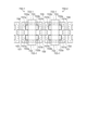
- FIG. 9 is a top plan view of the semiconductor substrate 101 in which the pixels 100 are formed
- FIGS. 11, 13, 15 and 17 show process cross-sectional views corresponding to the CC' cross-section in FIGS. 5 and 9.
- FIG. 9 is a top plan view of the semiconductor substrate 101 in which the pixels 100 are formed
- FIGS. 11, 13, 15 and 17 show process cross-sectional views corresponding to the CC' cross-section in FIGS. 5 and 9.
- an N-type dopant is ion-implanted into a semiconductor substrate 101 such as a silicon substrate from the upper surface side with a predetermined implantation energy.
- a photoelectric conversion portion 102 which is an N ⁇ type diffusion region, is formed in a region of the semiconductor substrate 101 which is biased toward the back surface side.
- a P ⁇ type semiconductor substrate may be used, or a P type dopant may be thinly diffused.
- the N ⁇ type refers to an N type with a small amount of free electrons
- the N+ type refers to an N type with a large amount of free electrons.
- P ⁇ type refers to P type with a small amount of holes
- P+ type refers to P type with a large amount of holes.
- a trench extending from the upper surface side to the rear surface side is formed in the region where the pixel isolation portion 109 for partitioning the semiconductor substrate 101 into individual pixel regions is to be formed.
- SiO 2 silicon nitride
- SiN silicon nitride
- a so-called FFT (Front Full Trench Isolation) type pixel isolation portion reaching from the top surface to the back surface of the semiconductor substrate 101 is exemplified.
- An FTI (Full Trench Isolation) type penetrating from the back side, or a DTI (Deep Trench Isolation) type or RDTI (Reverse Deep Trench Isolation) type pixel separation section formed from the front surface or the back surface to the middle of the semiconductor substrate 101 is adopted. is also possible.
- the trench formed in the semiconductor substrate 101 may be filled with a reflective material such as tungsten (W).
- W tungsten
- the pixel isolation portion 109 is not limited to a pixel isolation structure having a trench structure, and may have a pixel isolation structure with a diffusion region, for example.
- the pixel isolation portion 109 may be, for example, a diffusion region into which a dopant having a polarity opposite to that of the channel is implanted to a predetermined depth as a channel stopper.
- the semiconductor substrate 101 may be formed with not only the transfer gate 103 (transfer transistor TR) described later, but also other transistors forming the readout circuit 22 . That is, the imaging device 1 according to the present embodiment is not limited to the three-layer laminated structure described above with reference to FIG. may be
- an insulating film such as a silicon oxide film (SiO 2 ) is formed on the upper surface of the semiconductor substrate 101, and the insulating film is patterned by photolithography and etching to form trenches A1 in which transfer gates 103 are formed.
- a hard mask M1 is formed for the purpose.
- the opening shape of this hard mask is, for example, the same shape as the contour shape of the transfer gate 103 composed of the vertical gate electrodes 103-1 and 103-2 and the transfer gate electrode 103-3 when viewed from the thickness direction of the substrate. you can
- trenches A1 for forming transfer gates 103 are formed by etching the semiconductor substrate 101 through the openings of the hard mask M1 formed as described above.
- etching the semiconductor substrate 101 for example, anisotropic dry etching such as RIE (Reactive Ion Etching) can be used.
- RIE Reactive Ion Etching
- the trench A1 may be formed by various methods without being limited to this.
- a gate insulating film 104 is formed on the upper surface of the semiconductor substrate 101 and on the surface of the semiconductor substrate 101 in the trenches A1, as shown in FIGS. Annealing under an oxygen-rich condition can be used to form the gate insulating film 104 .
- the method is not limited to this, and the gate insulating film may be formed using a sputtering method, a CVD (Chemical Vapor Deposition) method, or the like.
- the insulating film formed on the upper surface of the semiconductor substrate 101 other than the inside of the trench A1 may be removed by CMP (Chemical Mechanical Polishing), wet etching, or the like.
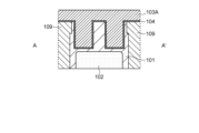
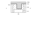
- a conductor layer 103A to be processed into the transfer gate 103 is formed on the upper surface of the semiconductor substrate 101 on which the gate insulating film 104 is formed and in the trench A1.
- the material of the conductor layer 103A polysilicon, amorphous silicon, or the like, which is conductive by containing impurities, may be used. However, it is not limited to this, and other conductive materials such as metals and alloys may be used.
- Various film forming techniques such as sputtering and CVD may be used to form the conductor layer 103A.
- the surface of the conductor layer 103A formed on the semiconductor substrate 101 may be planarized by, for example, CMP.
- a hard mask M2 is formed on the conductor layer 103A by performing a film formation process using sputtering or CVD and a patterning process using photolithography and etching.
- the opening shape of the hard mask M2 may be, for example, the same shape as the contour shape of the transfer gate electrode 103-3 in the transfer gate 103 when viewed from the thickness direction of the substrate.
- an insulating material such as a silicon nitride film (SiN) that can ensure an etching selectivity with respect to the gate insulating film 104 or the semiconductor substrate 101 may be used.
- the conductor layer 103A on the semiconductor substrate 101 is processed into the transfer gate electrode 103-3, and the conductor layer 103A in the trench A1 is exposed upward. It is processed into vertical gate electrodes 103-1 and 103-2 whose diameters are reduced on the sides. For example, by over-etching so that the conductor layer 103A in the trench A1 is removed to a certain depth, part of the conductor layer 103A in the trench A1 is removed to form enlarged diameter portions 103a and 103b below. It is possible to form vertical gate electrodes 103-1 and 103-2.
- RIE anisotropic dry etching may be used for patterning the conductor layer 103A.
- an insulating film is formed on the semiconductor substrate 101 with the transfer gates 103 formed thereon so as to fill the gaps in the trenches A1, and is patterned by photolithography and etching.
- an insulating film 107 having buried sidewalls 107a and 107b is formed on the side surfaces of the vertical gate electrodes 103-1 and 103-2.
- an insulating material that can ensure an etching selectivity with respect to the gate insulating film 104 may be used.
- the gate insulating film 104 is a silicon oxide film (SiO 2 )
- the insulating film 107 may be a silicon nitride film (SiN) or the like.
- a floating diffusion region 105 which is an N+ type diffusion region, is formed in one of the four corners of the pixel region in the upper layer portion of the semiconductor substrate 101 by, for example, ion implantation, and a P+ diffusion region 105 is formed in a corner diagonally opposite to this corner.
- a ground contact 106 which is a diffusion region of the mold, is formed by ion implantation, for example.
- the ion-implanted dopant may be stabilized by subjecting the upper surface of the semiconductor substrate 101 to annealing. After that, a passivation 110 made of an insulating film is formed on the upper surface of the semiconductor substrate 101 on which the transfer gate 103 is formed, thereby forming the pixel 100 having the structure shown in FIGS.
- the photoelectric conversion portion 102 side of each of the vertical gate electrodes 103-1 and 103-2 is expanded so as to protrude from the transfer gate electrode 103-3 ( enlarged diameter portions 103a and 103b).
- the transfer gate electrode 103-3 enlarged diameter portions 103a and 103b.
- the vertical gate electrodes 103-1 and 103-2 extend to the floating diffusion region 105. And/or it is possible to secure a distance to the ground contact 106, so that a strong electric field is formed between the vertical gate electrodes 103-1 and 103-2 and the floating diffusion region 105 and/or the ground contact 106. It is possible to suppress
- the transfer gate 103 and the floating diffusion region 105 and/or the ground contact 106 are separated from each other. Since the dielectric constant between them can be lowered, the strength of the electric field formed between the transfer gate 103 and the floating diffusion region 105 and/or the ground contact 106 can be further reduced.
- the pixel 200 may have a configuration corresponding to the pixel 2 provided on the first substrate 10 in the common configuration example described above. Also, the configurations, operations, manufacturing processes, and effects similar to those of the above-described embodiment will be omitted by citing them.
- FIG. 18 is a top view showing a schematic configuration example of a pixel according to this embodiment.
- FIG. 19 is a vertical sectional view showing a structural example of the A-A' section in FIG.
- a pixel 200 according to the present embodiment has a configuration similar to that of the pixel 100 described in the first embodiment with reference to FIGS. is replaced with a transfer gate 203 and an insulating film 207 .
- the transfer gate 203 is composed of a transfer gate electrode 103-3 similar to that of the first embodiment, and a plurality of vertical gate electrodes 203-1 and 203-2.
- the vertical gate electrodes 203-1 and 203-2 have the same structure as the vertical gate electrodes 103-1 and 103-2 according to the first embodiment, and are in contact with the pixel isolation portion 109 in the AA' cross-sectional direction. expanded to some extent.
- the transfer gate 203 and the semiconductor substrate 101 face each other with the gate insulating film 104 interposed therebetween is reduced. Since the size can be reduced, the parasitic capacitance between the transfer gate 203 and the semiconductor substrate 101 can be reduced, and the transfer efficiency can be improved.
- the vertical gate electrodes 203-1 and 203-2 are expressed as expanding in diameter, but this may also include reducing individual pixel regions partitioned by the pixel separation section 109. In that case, it is possible to increase the degree of freedom in layout design when the pixels 200 are miniaturized.
- the pixel 300 may have a configuration corresponding to the pixel 2 provided on the first substrate 10 in the common configuration example described above. Also, the configurations, operations, manufacturing processes, and effects similar to those of the above-described embodiment will be omitted by citing them.
- FIG. 20 is a vertical sectional view showing a schematic configuration example of a pixel according to this embodiment. Note that the A-A' cross section in FIG. 20 may correspond to the A-A' in FIG.
- a pixel 300 according to the present embodiment has a structure similar to that of the pixel 100 described in the first embodiment with reference to FIGS. With displaced structures.
- the film thickness of the portion of the gate insulating film 304 between the vertical gate electrode 103-1/103-2 and the pixel isolation portion 109 is thicker than the film thickness of the other portions.
- the thickness of the gate insulating film 304 provided between the vertical gate electrode 103-1/103-2 and the pixel separation section 109 on the side surface of the vertical gate electrode 103-1/103-2 is , is thicker than the gate insulating film 304 provided on the bottom surface of the vertical gate electrodes 103-1/103-2.
- the gate insulating film 304 between the vertical gate electrode 103-1/103-2 and the pixel isolation portion 109 By thickening the gate insulating film 304 between the vertical gate electrode 103-1/103-2 and the pixel isolation portion 109 in this manner, the parasitic capacitance between the transfer gate 203 and the semiconductor substrate 101 can be reduced. is possible, the transfer efficiency of charges accumulated in the photoelectric conversion unit 102 can be improved.
- the vertical gate electrode 103-1 and/or 103-2 and the pixel isolation portion 109 The gate insulating film 304 between and may be thick enough to be in contact with the pixel separation portion 109 .
- the present invention is not limited to this, and the vertical gate electrode 103-1 and/or 103-2 and the pixel isolation can be separated like the gate insulating film 304-2 between the vertical gate electrode 103-2 and the pixel isolation portion 109.
- the gate insulating film 304 between the portion 109 and the portion 109 may be thickened to the extent that it does not come into contact with the pixel separation portion 109 .
- the pixel 400 may have a configuration corresponding to the pixel 2 provided on the first substrate 10 in the common configuration example described above. Also, the configurations, operations, manufacturing processes, and effects similar to those of the above-described embodiment will be omitted by citing them.
- FIG. 21 is a vertical sectional view showing a schematic configuration example of a pixel according to this embodiment. Note that the A-A' cross section in FIG. 21 may correspond to the A-A' in FIG.
- a pixel 400 according to the present embodiment has a configuration similar to that of the pixel 100 described in the first embodiment with reference to FIGS. structure.
- the transfer gate 403 is composed of a transfer gate electrode 103-3 similar to that of the first embodiment, and a plurality of vertical gate electrodes 203-1 and 203-2.
- Each of the vertical gate electrodes 403-1 and 403-2 has a tapered shape in a vertical section parallel to the arrangement direction of the vertical gate electrodes 403-1 and 403-2, the diameter of which decreases toward the bottom surface.
- the vertical cross section parallel to the arrangement direction of the vertical gate electrodes 403-1 and 403-2 is, in other words, a plane perpendicular to a straight line connecting the floating diffusion region 105 and the ground contact 106.
- 103 and the floating diffusion region 105 is a plane perpendicular to the channel length direction of the channel.
- the pixel 500 may have a configuration corresponding to the pixel 2 provided on the first substrate 10 in the common configuration example described above. Also, the configurations, operations, manufacturing processes, and effects similar to those of the above-described embodiment will be omitted by citing them.
- FIG. 22 is a vertical sectional view showing a schematic configuration example of a pixel according to this embodiment. Note that the C-C' section in FIG. 22 may correspond to the C-C' in FIG.
- a pixel 500 according to the present embodiment has a configuration similar to that of the pixel 100 described in the first embodiment with reference to FIGS. 503 and an insulating film 507 are replaced.
- the transfer gate 503 includes a transfer gate electrode 103-3 similar to that of the first embodiment, and a plurality of vertical gate electrodes 503-1 and 503-2 (however, FIG. 22 shows only the vertical gate electrode 503-1). ) and
- the vertical gate electrodes 503-1 and 503-2 are expanded on the floating diffusion region 105 side and the ground contact 106 side in the same structure as the vertical gate electrodes 103-1 and 103-2 according to the first embodiment.
- the diameter portions 503a and 503b have different depths in the substrate thickness direction (depth direction).
- the enlarged diameter portion 503b on the floating diffusion region 105 side is set at a deeper position in the depth direction of the upper surface than the enlarged diameter portion 503a on the ground contact 106 side.
- the present invention is not limited to this, and the enlarged diameter portion 503a on the side of the ground contact 106 may be set at a deeper position in the depth direction of the upper surface than the enlarged diameter portion 503b on the side of the floating diffusion region 105. .
- the insulating film 507 fills the trench A1 (see FIG. 15, for example) according to the difference in the depth direction between the enlarged diameter portions 503a and 503b in the same structure as the insulating film 107 according to the first embodiment. is configured as
- the depth of the expanded diameter portions 503a and 503b in the substrate thickness direction is different between the floating diffusion region 105 side and the ground contact 106 side, thereby increasing the process margin during manufacturing. becomes possible.
- the distance from the side surface of the trench A1 (the width in the channel direction) between the floating diffusion region 105 side and the ground contact 106 side with the hard mask M2 interposed therebetween is The conductor layer 103A tends to be carved deeper on the side of the floating diffusion region 105 with a larger .DELTA.D. can be suppressed.
- the pixel 600 may have a configuration corresponding to the pixel 2 provided on the first substrate 10 in the common configuration example described above. Also, the configurations, operations, manufacturing processes, and effects similar to those of the above-described embodiment will be omitted by citing them.
- FIG. 23 is a vertical sectional view showing a schematic configuration example of a pixel according to this embodiment. Note that the C-C' section in FIG. 23 may correspond to the C-C' in FIG.
- a pixel 600 according to the present embodiment has a configuration similar to that of the pixel 100 described in the first embodiment with reference to FIGS. 603 and the structure replaced with an insulating film 607 .
- the transfer gate 603 includes a transfer gate electrode 103-3 similar to that of the first embodiment, and a plurality of vertical gate electrodes 603-1 and 603-2 (however, FIG. 23 shows only the vertical gate electrode 603-1). ) and
- the vertical gate electrodes 603-1 and 603-2 have the same structure as the vertical gate electrodes 103-1 and 103-2 according to the first embodiment, but have the enlarged diameter portions 103a and 103b omitted. .
- the insulating film 607 is configured to fill the trench A1 (see FIG. 15, for example) instead of the omitted enlarged diameter portions 103a and 103b.
- the parasitics between the transfer gate 603 and the semiconductor substrate 101 can be reduced. Since the capacity can be reduced, the transfer efficiency of charges accumulated in the photoelectric conversion unit 102 can be improved.
- the pixels 700-1 and 700-2 may have a configuration corresponding to the pixel 2 provided on the first substrate 10 in the common configuration example described above. Also, the configurations, operations, manufacturing processes, and effects similar to those of the above-described embodiment will be omitted by citing them.
- one pixel 100, 200, 300, 400, 500 or 600 includes one floating diffusion region 105 is exemplified. It may be a structure that shares a floating diffusion region. Therefore, in the seventh embodiment, two pixels 2 share one floating diffusion region.
- FIG. 24 is a plan view showing a schematic configuration example of a pixel according to this embodiment.
- two pixels 700-1 and 700-2 adjacent in the row direction share one floating diffusion region 705.
- each of the pixels 700-1 and 700-2 may share the ground contact 706 with adjacent pixels on opposite sides in the row direction.
- the reference numeral is '700'.
- Each pixel 700 has a configuration in which a photoelectric conversion section 102 , a transfer gate 703 , and an insulating film 707 are provided in a pixel region of the semiconductor substrate 101 partitioned by the pixel separation section 109 .
- Each pixel 700 may include a gate insulating film 104, sidewalls 108, and passivation 110 (not shown).
- the transfer gate 703 includes a transfer gate electrode 703-3 that traverses the pixel region in the column direction (vertical direction in the drawing), and a plurality of (two in this example) arranged in the column direction along the transfer gate electrode 703-3. It is composed of vertical gate electrodes 703-1 and 703-2, and has a ⁇ shape as a whole. Enlarged diameter portions 703a and 703b are provided on the bottom side of each of the vertical gate electrodes 703-1 and 703-2.
- the insulating film 707 includes buried sidewalls 707a interposed between the vertical gate electrodes 703-1 and 7-3-2 and the ground contact 706, and the vertical gate electrodes 703-1 and 7-3. -2 and a buried sidewall 707b interposed between the floating diffusion region 705 and configured to cover the transfer gate 703, for example.
- the floating diffusion region 705 shared by the two pixels 700-1 and 700-2 is configured to straddle the pixel separation section 109 that separates the two pixels 700-1 and 700-2.
- the floating diffusion regions 705 are configured to connect the diffusion regions formed near the opposite sides of the pixel regions of the two pixels 700-1 and 700-2 and the diffusion regions on the semiconductor substrate 101. It is composed of a conductive film.
- the ground contact 706 shared by the two pixels 700 is, for example, a diffusion region formed near the opposite sides of the pixel regions of the two pixels 700 and a diffusion region connecting the diffusion regions on the semiconductor substrate 101 . and a conductive film composed of
- the vertical gate electrodes 703-1 and 703-2 on the photoelectric conversion unit 102 side are protruded from the transfer gate electrode 703-3. to increase the area of the surface of the transfer gate 703 facing the photoelectric conversion unit 102 while securing the distance from the transfer gate electrode 703-3 to the floating diffusion region 705 and/or the ground contact 706. is possible, it is possible to suppress the deterioration of the transfer efficiency while suppressing the deterioration of the image quality due to the formation of the strong electric field.
- the pixels 800-1 to 800-4 may have a configuration corresponding to the pixel 2 provided on the first substrate 10 in the common configuration example described above. Also, the configurations, operations, manufacturing processes, and effects similar to those of the above-described embodiment will be omitted by citing them.
- two pixels 700 share one floating diffusion region 705.
- four pixels 800-1 to 800-4 share one floating diffusion region.
- a case of sharing a diffusion region is exemplified.
- FIG. 25 is a plan view showing a schematic configuration example of a pixel according to this embodiment.
- four pixels 800-1 to 800-4 arranged in 2 ⁇ 2 form share one floating diffusion region 805.
- each of the pixels 800-1 to 800-4 may share the ground contact 806 with the adjacent pixel on the opposite side in the oblique direction (also called diagonal direction).
- the reference numeral is '800'.
- Each pixel 800 may have, for example, a structure similar to any of the pixels 100, 200, 300, 400, 500 and 600 illustrated in the first to sixth embodiments above.
- the pixels 800-1 to 800-4 may be oriented so that the floating diffusion regions 105 are clustered in the center of the 2 ⁇ 2 array.
- the floating diffusion regions 805 shared by the four pixels 800-1 to 800-4 are configured to connect the floating diffusion regions 105 gathered in the center on the semiconductor substrate 101. It is composed of a conductive film.
- the ground contacts 806 shared by the four pixels 800 are, for example, the ground contacts 106 gathered in the center of the 2 ⁇ 2 array and the conductive film configured to connect them on the semiconductor substrate 101. consists of
- the vertical gate electrodes 103-1 and 103-2 on the photoelectric conversion unit 102 side are arranged to protrude from the transfer gate electrode 103-3. to increase the area of the surface of the transfer gate 103 facing the photoelectric conversion unit 102 while securing the distance from the transfer gate electrode 103-3 to the floating diffusion region 805 and/or the ground contact 806. is possible, it is possible to suppress the deterioration of the transfer efficiency while suppressing the deterioration of the image quality due to the formation of the strong electric field.
- the pixels 900-1 and 900-2 may have a configuration corresponding to the pixel 2 provided on the first substrate 10 in the common configuration example described above. Also, the configurations, operations, manufacturing processes, and effects similar to those of the above-described embodiment will be omitted by citing them.
- each pixel 100, 200, 300, 400, 500, 600, 700, or 800 is provided in a substantially square pixel region separated by the pixel separator 109.
- the shape is not limited to a substantially square shape, and can be variously modified such as a rectangle, a trapezoid, a rhombus, a regular hexagon, a circle, and an ellipse. Therefore, in the ninth embodiment, a case where each pixel area is divided into long rectangles in the column direction will be exemplified.
- FIG. 26 is a plan view showing a schematic configuration example of a pixel according to this embodiment. As shown in FIG. 26, in the present embodiment, each pixel region partitioned by the pixel separating portion 109 has a rectangular shape elongated in the column direction.
- Each pixel region is provided with an element structure that forms a pixel 900-1 or 900-2 on one side in the longitudinal direction of the rectangle.
- the reference numeral is '900'.
- each pixel 900 may be any element structure of the pixels 100, 200, 300, 400, 500, or 600 according to the above-described embodiments.
- the photoelectric conversion unit 102 is replaced with a photoelectric conversion unit 902 extending over the entire pixel area.
- the floating diffusion region 905 includes, for example, a diffusion region formed at a corner where the side where the element structure is arranged closely and the side facing the other pixel 900 sharing the floating diffusion region 905 intersects, and these diffusion regions It may be composed of a conductive film connected across the pixel separation portion 109 .
- the ground contact 906 is a diffusion region formed at a corner where, for example, the side opposite to the side where the element structures are closely arranged and the side facing the other pixel 900 sharing the floating diffusion region 905 intersect. and a conductive film that connects these diffusion regions across the pixel isolation portion 109 .
- the diameter of each of the vertical gate electrodes 103-1 and 103-2 on the photoelectric conversion unit 102 side is expanded so as to protrude from the transfer gate electrode 103-3.
- This makes it possible to increase the area of the surface of the transfer gate 103 facing the photoelectric conversion unit 102 while ensuring the distance from the transfer gate electrode 103-3 to the floating diffusion region 905 and/or the ground contact 906. Therefore, it is possible to suppress the deterioration of the transfer efficiency while suppressing the deterioration of the image quality due to the formation of the strong electric field.
- the vertical gate electrodes 103-1 and 103-2 each have a structure in which the bottom side is wider than the top side, so that the transfer gate electrode 103- 3 to the floating diffusion region 105 and/or the ground contact 106, the area of the surface (bottom surface) of the transfer gate 103 facing the photoelectric conversion unit 102 is increased.
- the transfer gate 103 Since it is possible to secure an electrical distance to the floating diffusion region 105 and/or the ground contact 106, the transfer gate 103 and the floating diffusion region 105 and/or the ground contact 106 can be separated from each other while suppressing a decrease in transfer efficiency. This suppresses deterioration in image quality due to the formation of a strong electric field between them.
- the present embodiment exemplifies a structure capable of ensuring a longer electrical distance from the transfer gate 103 to the floating diffusion region 105 and/or the ground contact 106. According to the structure according to the present embodiment, it is possible to further suppress deterioration in image quality due to formation of a strong electric field between the transfer gate 103 and the floating diffusion region 105 and/or the ground contact 106 .
- FIG. 27 is a partial cross-sectional view showing a structural example of a pixel according to this embodiment. 27 shows the structure around the transfer gate electrode 1003 extracted from the sectional structure of the plane corresponding to the section C-C' shown in FIG. 8 in the first embodiment.
- a trench A1 for providing a transfer gate has a structure whose diameter increases as it approaches the surface (element formation surface) of the semiconductor substrate 101.
- a vertical gate electrode 1003-1 having enlarged diameter portions 103a and 103b and an insulating film 1007 including buried sidewalls 1007a and 1007b are provided. Therefore, in the present embodiment, the buried sidewalls 1007a and 1007b have a structure in which the diameter increases as they approach the surface (element formation surface) of the semiconductor substrate 101.
- the embedded sidewalls 1007a and 1007b on the surface (element formation surface) side of the semiconductor substrate 101 are configured to be further enlarged by providing the step A1007 on the inner side surface of the trench A1.
- the structure of the enlarged diameter portions 103a and 103b according to the tenth embodiment (and other embodiments) described above is such that the bottoms of the vertical gate electrodes 1003-1/1003-2 are parallel to the element forming surface of the semiconductor substrate 101. It is not limited to a structure projecting in any direction.
- FIG. 28 is a partial cross-sectional view showing a structural example of a pixel according to this embodiment. 28, similarly to the tenth embodiment, the structure around the transfer gate electrode 1103 is extracted from the cross-sectional structure of the plane corresponding to the CC' cross section shown in FIG. 8 in the first embodiment. shown as
- this embodiment has a structure in which the enlarged diameter portions 1103a and 1103b are curved up along the inner side surface of the trench A1. That is, this embodiment has a structure in which the upper surfaces of the enlarged diameter portions 1103a and 1103b are warped outward, thereby increasing the diameter of the upper surfaces of the enlarged diameter portions 1103a and 1103b outward.
- the area of the surface of the vertical gate electrode 1103-1 facing the semiconductor substrate 101 can be increased. can be improved.
- the photoelectric conversion portion 102 can be provided to a shallower position of the semiconductor substrate 101. Become. As a result, the photoelectric conversion area can be expanded, and the photosensitivity of the pixels 2 can be further increased.
- the technology according to the present disclosure can be applied to various products.
- the technology according to the present disclosure can be realized as a device mounted on any type of moving body such as automobiles, electric vehicles, hybrid electric vehicles, motorcycles, bicycles, personal mobility, airplanes, drones, ships, and robots. may
- FIG. 29 is a block diagram showing a schematic configuration example of a vehicle control system, which is an example of a mobile control system to which the technology according to the present disclosure can be applied.
- a vehicle control system 12000 includes a plurality of electronic control units connected via a communication network 12001.
- the vehicle control system 12000 includes a drive system control unit 12010, a body system control unit 12020, an outside information detection unit 12030, an inside information detection unit 12040, and an integrated control unit 12050.
- a microcomputer 12051, an audio/image output unit 12052, and an in-vehicle network I/F (interface) 12053 are illustrated.
- the drive system control unit 12010 controls the operation of devices related to the drive system of the vehicle according to various programs.
- the driving system control unit 12010 includes a driving force generator for generating driving force of the vehicle such as an internal combustion engine or a driving motor, a driving force transmission mechanism for transmitting the driving force to the wheels, and a steering angle of the vehicle. It functions as a control device such as a steering mechanism to adjust and a brake device to generate braking force of the vehicle.
- the body system control unit 12020 controls the operation of various devices equipped on the vehicle body according to various programs.
- the body system control unit 12020 functions as a keyless entry system, a smart key system, a power window device, or a control device for various lamps such as headlamps, back lamps, brake lamps, winkers or fog lamps.
- the body system control unit 12020 can receive radio waves transmitted from a portable device that substitutes for a key or signals from various switches.
- the body system control unit 12020 receives the input of these radio waves or signals and controls the door lock device, power window device, lamps, etc. of the vehicle.
- the vehicle exterior information detection unit 12030 detects information outside the vehicle in which the vehicle control system 12000 is installed.
- the vehicle exterior information detection unit 12030 is connected with an imaging section 12031 .
- the vehicle exterior information detection unit 12030 causes the imaging unit 12031 to capture an image of the exterior of the vehicle, and receives the captured image.
- the vehicle exterior information detection unit 12030 may perform object detection processing or distance detection processing such as people, vehicles, obstacles, signs, or characters on the road surface based on the received image.
- the imaging unit 12031 is an optical sensor that receives light and outputs an electrical signal according to the amount of received light.
- the imaging unit 12031 can output the electric signal as an image, and can also output it as distance measurement information.
- the light received by the imaging unit 12031 may be visible light or non-visible light such as infrared rays.
- the in-vehicle information detection unit 12040 detects in-vehicle information.
- the in-vehicle information detection unit 12040 is connected to, for example, a driver state detection section 12041 that detects the state of the driver.
- the driver state detection unit 12041 includes, for example, a camera that captures an image of the driver, and the in-vehicle information detection unit 12040 detects the degree of fatigue or concentration of the driver based on the detection information input from the driver state detection unit 12041. It may be calculated, or it may be determined whether the driver is dozing off.
- the microcomputer 12051 calculates control target values for the driving force generator, the steering mechanism, or the braking device based on the information inside and outside the vehicle acquired by the vehicle exterior information detection unit 12030 or the vehicle interior information detection unit 12040, and controls the drive system control unit.
- a control command can be output to 12010 .
- the microcomputer 12051 realizes the functions of ADAS (Advanced Driver Assistance System) including collision avoidance or shock mitigation, follow-up driving based on inter-vehicle distance, vehicle speed maintenance driving, vehicle collision warning, or vehicle lane deviation warning. Cooperative control can be performed for the purpose of ADAS (Advanced Driver Assistance System) including collision avoidance or shock mitigation, follow-up driving based on inter-vehicle distance, vehicle speed maintenance driving, vehicle collision warning, or vehicle lane deviation warning. Cooperative control can be performed for the purpose of ADAS (Advanced Driver Assistance System) including collision avoidance or shock mitigation, follow-up driving based on inter-vehicle distance, vehicle speed maintenance driving, vehicle collision warning, or vehicle
- the microcomputer 12051 controls the driving force generator, the steering mechanism, the braking device, etc. based on the information about the vehicle surroundings acquired by the vehicle exterior information detection unit 12030 or the vehicle interior information detection unit 12040, so that the driver's Cooperative control can be performed for the purpose of autonomous driving, etc., in which vehicles autonomously travel without depending on operation.
- the microcomputer 12051 can output a control command to the body system control unit 12020 based on the information outside the vehicle acquired by the information detection unit 12030 outside the vehicle.
- the microcomputer 12051 controls the headlamps according to the position of the preceding vehicle or the oncoming vehicle detected by the vehicle exterior information detection unit 12030, and performs cooperative control aimed at anti-glare such as switching from high beam to low beam. It can be carried out.
- the audio/image output unit 12052 transmits at least one of audio and/or image output signals to an output device capable of visually or audibly notifying the passengers of the vehicle or the outside of the vehicle.
- an audio speaker 12061, a display unit 12062, and an instrument panel 12063 are illustrated as output devices.
- the display unit 12062 may include at least one of an on-board display and a head-up display, for example.
- FIG. 30 is a diagram showing an example of the installation position of the imaging unit 12031.
- the vehicle 12100 has imaging units 12101, 12102, 12103, 12104, and 12105 as the imaging unit 12031.
- the imaging units 12101, 12102, 12103, 12104, and 12105 are provided at positions such as the front nose of the vehicle 12100, the side mirrors, the rear bumper, the back door, and the upper part of the windshield in the vehicle interior, for example.
- An image pickup unit 12101 provided in the front nose and an image pickup unit 12105 provided above the windshield in the passenger compartment mainly acquire images in front of the vehicle 12100 .
- Imaging units 12102 and 12103 provided in the side mirrors mainly acquire side images of the vehicle 12100 .
- An imaging unit 12104 provided in the rear bumper or back door mainly acquires an image behind the vehicle 12100 .
- Forward images acquired by the imaging units 12101 and 12105 are mainly used for detecting preceding vehicles, pedestrians, obstacles, traffic lights, traffic signs, lanes, and the like.
- FIG. 30 shows an example of the imaging range of the imaging units 12101 to 12104.
- the imaging range 12111 indicates the imaging range of the imaging unit 12101 provided in the front nose
- the imaging ranges 12112 and 12113 indicate the imaging ranges of the imaging units 12102 and 12103 provided in the side mirrors, respectively
- the imaging range 12114 The imaging range of an imaging unit 12104 provided on the rear bumper or back door is shown. For example, by superimposing the image data captured by the imaging units 12101 to 12104, a bird's-eye view image of the vehicle 12100 viewed from above can be obtained.
- At least one of the imaging units 12101 to 12104 may have a function of acquiring distance information.
- at least one of the imaging units 12101 to 12104 may be a stereo camera composed of a plurality of imaging elements, or may be an imaging element having pixels for phase difference detection.
- the microcomputer 12051 determines the distance to each three-dimensional object within the imaging ranges 12111 to 12114 and changes in this distance over time (relative velocity with respect to the vehicle 12100). , it is possible to extract, as the preceding vehicle, the closest three-dimensional object on the course of the vehicle 12100, which runs at a predetermined speed (for example, 0 km/h or more) in substantially the same direction as the vehicle 12100. can. Furthermore, the microcomputer 12051 can set the inter-vehicle distance to be secured in advance in front of the preceding vehicle, and perform automatic brake control (including following stop control) and automatic acceleration control (including following start control). In this way, cooperative control can be performed for the purpose of automatic driving in which the vehicle runs autonomously without relying on the operation of the driver.
- automatic brake control including following stop control
- automatic acceleration control including following start control
- the microcomputer 12051 converts three-dimensional object data related to three-dimensional objects to other three-dimensional objects such as motorcycles, ordinary vehicles, large vehicles, pedestrians, and utility poles. It can be classified and extracted and used for automatic avoidance of obstacles. For example, the microcomputer 12051 distinguishes obstacles around the vehicle 12100 into those that are visible to the driver of the vehicle 12100 and those that are difficult to see. Then, the microcomputer 12051 judges the collision risk indicating the degree of danger of collision with each obstacle, and when the collision risk is equal to or higher than the set value and there is a possibility of collision, the obstacle is detected through the audio speaker 12061 and the display unit 12062. By outputting an alarm to the driver via the drive system control unit 12010 and performing forced deceleration and avoidance steering via the drive system control unit 12010, driving assistance for collision avoidance can be performed.
- At least one of the imaging units 12101 to 12104 may be an infrared camera that detects infrared rays.
- the microcomputer 12051 can recognize a pedestrian by determining whether or not the pedestrian exists in the captured images of the imaging units 12101 to 12104 .
- recognition of a pedestrian is performed by, for example, a procedure for extracting feature points in images captured by the imaging units 12101 to 12104 as infrared cameras, and performing pattern matching processing on a series of feature points indicating the outline of an object to determine whether or not the pedestrian is a pedestrian.
- the audio image output unit 12052 outputs a rectangular outline for emphasis to the recognized pedestrian. is superimposed on the display unit 12062 . Also, the audio/image output unit 12052 may control the display unit 12062 to display an icon or the like indicating a pedestrian at a desired position.
- the technology according to the present disclosure can be applied to the imaging unit 12031 among the configurations described above.
- the technology according to the present disclosure can be applied to the imaging unit 12031, it is possible to acquire an image with good image quality, so that various effects such as being able to improve the accuracy of various detection processes can be achieved. becomes possible.
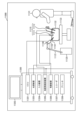
- FIG. 31 is a diagram showing an example of a schematic configuration of an endoscopic surgery system to which the technology according to the present disclosure (this technology) can be applied.
- FIG. 31 shows how an operator (physician) 11131 is performing surgery on a patient 11132 on a patient bed 11133 using an endoscopic surgery system 11000 .
- an endoscopic surgery system 11000 includes an endoscope 11100, other surgical instruments 11110 such as a pneumoperitoneum tube 11111 and an energy treatment instrument 11112, and a support arm device 11120 for supporting the endoscope 11100. , and a cart 11200 loaded with various devices for endoscopic surgery.
- An endoscope 11100 is composed of a lens barrel 11101 whose distal end is inserted into the body cavity of a patient 11132 and a camera head 11102 connected to the proximal end of the lens barrel 11101 .
- an endoscope 11100 configured as a so-called rigid scope having a rigid lens barrel 11101 is illustrated, but the endoscope 11100 may be configured as a so-called flexible scope having a flexible lens barrel. good.
- the tip of the lens barrel 11101 is provided with an opening into which the objective lens is fitted.
- a light source device 11203 is connected to the endoscope 11100, and light generated by the light source device 11203 is guided to the tip of the lens barrel 11101 by a light guide extending inside the lens barrel 11101, where it reaches the objective. Through the lens, the light is irradiated toward the observation object inside the body cavity of the patient 11132 .
- the endoscope 11100 may be a straight scope, a perspective scope, or a side scope.
- An optical system and an imaging element are provided inside the camera head 11102, and the reflected light (observation light) from the observation target is focused on the imaging element by the optical system.
- the imaging element photoelectrically converts the observation light to generate an electric signal corresponding to the observation light, that is, an image signal corresponding to the observation image.
- the image signal is transmitted to a camera control unit (CCU: Camera Control Unit) 11201 as RAW data.
- CCU Camera Control Unit
- the CCU 11201 is composed of a CPU (Central Processing Unit), a GPU (Graphics Processing Unit), etc., and controls the operations of the endoscope 11100 and the display device 11202 in an integrated manner. Further, the CCU 11201 receives an image signal from the camera head 11102 and performs various image processing such as development processing (demosaicing) for displaying an image based on the image signal.
- CPU Central Processing Unit
- GPU Graphics Processing Unit
- the display device 11202 displays an image based on an image signal subjected to image processing by the CCU 11201 under the control of the CCU 11201 .
- the light source device 11203 is composed of a light source such as an LED (Light Emitting Diode), for example, and supplies the endoscope 11100 with irradiation light for photographing a surgical site or the like.
- a light source such as an LED (Light Emitting Diode), for example, and supplies the endoscope 11100 with irradiation light for photographing a surgical site or the like.
- the input device 11204 is an input interface for the endoscopic surgery system 11000.
- the user can input various information and instructions to the endoscopic surgery system 11000 via the input device 11204 .
- the user inputs an instruction or the like to change imaging conditions (type of irradiation light, magnification, focal length, etc.) by the endoscope 11100 .
- the treatment instrument control device 11205 controls driving of the energy treatment instrument 11112 for tissue cauterization, incision, blood vessel sealing, or the like.
- the pneumoperitoneum device 11206 inflates the body cavity of the patient 11132 for the purpose of securing the visual field of the endoscope 11100 and securing the operator's working space, and injects gas into the body cavity through the pneumoperitoneum tube 11111. send in.
- the recorder 11207 is a device capable of recording various types of information regarding surgery.
- the printer 11208 is a device capable of printing various types of information regarding surgery in various formats such as text, images, and graphs.
- the light source device 11203 that supplies the endoscope 11100 with irradiation light for photographing the surgical site can be composed of, for example, a white light source composed of an LED, a laser light source, or a combination thereof.
- a white light source is configured by a combination of RGB laser light sources
- the output intensity and output timing of each color (each wavelength) can be controlled with high accuracy. It can be carried out.
- the observation target is irradiated with laser light from each of the RGB laser light sources in a time-division manner, and by controlling the drive of the imaging element of the camera head 11102 in synchronization with the irradiation timing, each of RGB can be handled. It is also possible to pick up images by time division. According to this method, a color image can be obtained without providing a color filter in the imaging element.
- the driving of the light source device 11203 may be controlled so as to change the intensity of the output light every predetermined time.
- the drive of the imaging device of the camera head 11102 in synchronism with the timing of the change in the intensity of the light to obtain an image in a time-division manner and synthesizing the images, a high dynamic A range of images can be generated.
- the light source device 11203 may be configured to be able to supply light in a predetermined wavelength band corresponding to special light observation.
- special light observation for example, the wavelength dependence of light absorption in body tissues is used to irradiate a narrower band of light than the irradiation light (i.e., white light) used during normal observation, thereby observing the mucosal surface layer.
- narrow band imaging in which a predetermined tissue such as a blood vessel is imaged with high contrast, is performed.
- fluorescence observation may be performed in which an image is obtained from fluorescence generated by irradiation with excitation light.
- the body tissue is irradiated with excitation light and the fluorescence from the body tissue is observed (autofluorescence observation), or a reagent such as indocyanine green (ICG) is locally injected into the body tissue and the body tissue is A fluorescence image can be obtained by irradiating excitation light corresponding to the fluorescence wavelength of the reagent.
- the light source device 11203 can be configured to be able to supply narrowband light and/or excitation light corresponding to such special light observation.
- FIG. 32 is a block diagram showing an example of functional configurations of the camera head 11102 and CCU 11201 shown in FIG.
- the camera head 11102 has a lens unit 11401, an imaging section 11402, a drive section 11403, a communication section 11404, and a camera head control section 11405.
- the CCU 11201 has a communication section 11411 , an image processing section 11412 and a control section 11413 .
- the camera head 11102 and the CCU 11201 are communicably connected to each other via a transmission cable 11400 .
- a lens unit 11401 is an optical system provided at a connection with the lens barrel 11101 . Observation light captured from the tip of the lens barrel 11101 is guided to the camera head 11102 and enters the lens unit 11401 .
- a lens unit 11401 is configured by combining a plurality of lenses including a zoom lens and a focus lens.
- the imaging unit 11402 is composed of an imaging element.
- the imaging device constituting the imaging unit 11402 may be one (so-called single-plate type) or plural (so-called multi-plate type).
- image signals corresponding to RGB may be generated by each image pickup element, and a color image may be obtained by synthesizing the image signals.
- the imaging unit 11402 may be configured to have a pair of imaging elements for respectively acquiring right-eye and left-eye image signals corresponding to 3D (Dimensional) display.
- the 3D display enables the operator 11131 to more accurately grasp the depth of the living tissue in the surgical site.
- a plurality of systems of lens units 11401 may be provided corresponding to each imaging element.
- the imaging unit 11402 does not necessarily have to be provided in the camera head 11102 .
- the imaging unit 11402 may be provided inside the lens barrel 11101 immediately after the objective lens.
- the drive unit 11403 is configured by an actuator, and moves the zoom lens and focus lens of the lens unit 11401 by a predetermined distance along the optical axis under control from the camera head control unit 11405 . Thereby, the magnification and focus of the image captured by the imaging unit 11402 can be appropriately adjusted.
- the communication unit 11404 is composed of a communication device for transmitting and receiving various information to and from the CCU 11201.
- the communication unit 11404 transmits the image signal obtained from the imaging unit 11402 as RAW data to the CCU 11201 via the transmission cable 11400 .
- the communication unit 11404 receives a control signal for controlling driving of the camera head 11102 from the CCU 11201 and supplies it to the camera head control unit 11405 .
- the control signal includes, for example, information to specify the frame rate of the captured image, information to specify the exposure value at the time of imaging, and/or information to specify the magnification and focus of the captured image. Contains information about conditions.
- the imaging conditions such as the frame rate, exposure value, magnification, and focus may be appropriately designated by the user, or may be automatically set by the control unit 11413 of the CCU 11201 based on the acquired image signal. good.
- the endoscope 11100 is equipped with so-called AE (Auto Exposure) function, AF (Auto Focus) function, and AWB (Auto White Balance) function.
- the camera head control unit 11405 controls driving of the camera head 11102 based on the control signal from the CCU 11201 received via the communication unit 11404.
- the communication unit 11411 is composed of a communication device for transmitting and receiving various information to and from the camera head 11102 .
- the communication unit 11411 receives image signals transmitted from the camera head 11102 via the transmission cable 11400 .
- the communication unit 11411 transmits a control signal for controlling driving of the camera head 11102 to the camera head 11102 .
- Image signals and control signals can be transmitted by electric communication, optical communication, or the like.
- the image processing unit 11412 performs various types of image processing on the image signal, which is RAW data transmitted from the camera head 11102 .
- the control unit 11413 performs various controls related to imaging of the surgical site and the like by the endoscope 11100 and display of the captured image obtained by imaging the surgical site and the like. For example, the control unit 11413 generates control signals for controlling driving of the camera head 11102 .
- control unit 11413 causes the display device 11202 to display a captured image showing the surgical site and the like based on the image signal that has undergone image processing by the image processing unit 11412 .
- the control unit 11413 may recognize various objects in the captured image using various image recognition techniques. For example, the control unit 11413 detects the shape, color, and the like of the edges of objects included in the captured image, thereby detecting surgical instruments such as forceps, specific body parts, bleeding, mist during use of the energy treatment instrument 11112, and the like. can recognize.
- the control unit 11413 may use the recognition result to display various types of surgical assistance information superimposed on the image of the surgical site. By superimposing and presenting the surgery support information to the operator 11131, the burden on the operator 11131 can be reduced and the operator 11131 can proceed with the surgery reliably.
- a transmission cable 11400 connecting the camera head 11102 and the CCU 11201 is an electrical signal cable compatible with electrical signal communication, an optical fiber compatible with optical communication, or a composite cable of these.
- wired communication is performed using the transmission cable 11400, but communication between the camera head 11102 and the CCU 11201 may be performed wirelessly.
- the technology according to the present disclosure can be applied to, for example, the endoscope 11100, (the imaging unit 11402 of) the camera head 11102, (the image processing unit 11412 of) the CCU 11201, and the like among the configurations described above.
- the technology according to the present disclosure can be applied to these configurations, a clearer image of the surgical site can be obtained, so that the operator can reliably confirm the surgical site.
- the technology according to the present disclosure may also be applied to, for example, a microsurgery system.
- the present technology can also take the following configuration.
- (1) comprising a plurality of pixels arranged in a two-dimensional lattice, Each of said pixels includes: a photoelectric conversion unit that is provided on the first surface side of the semiconductor substrate and photoelectrically converts incident light; a vertical gate electrode provided on the semiconductor substrate so as to approach the photoelectric conversion portion from a second surface side opposite to the first surface; a gate insulating film provided between the vertical gate electrode and the semiconductor substrate; a transfer gate electrode connected to the vertical gate electrode on the second surface of the semiconductor substrate; a first diffusion region provided on the second surface side of the semiconductor substrate; with The imaging device, wherein the vertical gate electrode has a structure in which a bottom portion on the side of the photoelectric conversion portion is larger in diameter than an upper portion on the side of the transfer gate electrode.
- Each of the pixels further includes an insulating film provided on the upper side surface of the vertical gate electrode and between at least the vertical gate electrode and the first diffusion region.
- imaging device. (3) further comprising a pixel separation section that partitions the second surface of the semiconductor substrate into a plurality of pixel regions; The imaging device according to (1) or (2), wherein the pixels are provided in one-to-one correspondence with the pixel regions.
- each of the pixels further includes a second diffusion region provided on the second surface side of the semiconductor substrate; the first diffusion region is arranged at one corner of a plurality of corners of the pixel region; The imaging according to (3) above, wherein the second diffusion region is arranged at a corner of the plurality of corners of the pixel region that is diagonal to a corner where the first diffusion region is arranged.
- the imaging device (5) The imaging device according to (4), wherein the vertical gate electrode is composed of a plurality of vertical gate electrodes including a first vertical gate electrode and a second vertical gate electrode. (6) The first vertical gate electrode and the second vertical gate electrode are arranged line-symmetrically with respect to a center line connecting the first diffusion region and the second diffusion region. 5) The imaging device according to the above. (7) The imaging device according to any one of (4) to (6), wherein at least a part of the side surface of the vertical gate electrode is in contact with the pixel separation section with the gate insulating film interposed therebetween.
- the thickness of the gate insulating film provided between the pixel separation portion and the side surface of the vertical gate electrode is larger than the thickness of the gate insulating film provided on the bottom surface of the vertical gate electrode.
- the imaging device according to any one of (4) to (7) above.
- the cross-sectional shape of the vertical gate electrode in a plane perpendicular to a straight line connecting the first diffusion region and the second diffusion region is a tapered shape that decreases in diameter as it approaches the bottom surface. ).
- the bottom portion of the vertical gate electrode includes a first enlarged diameter portion projecting toward the first diffusion region and a second enlarged diameter portion projecting toward the second diffusion region; Any one of (4) to (9) above, wherein the distance from the second surface of the upper surface of the first enlarged diameter portion is different from the distance from the second surface of the upper surface of the second enlarged diameter portion.
- the imaging device according to 1. (11) The imaging device according to any one of (3) to (10), wherein the shape of the pixel area on the first surface is any one of a square, rectangle, trapezoid, rhombus, and regular hexagon. (12) The imaging device according to any one of (1) to (11), wherein the first diffusion region is shared by two or more of the pixels.
- Imaging device 2 100, 200, 300, 400, 500, 600, 700-1 to 700-2, 800-1 to 800-4, 900-1 to 900-2 pixel 3 pixel array section 4 vertical drive circuit 5
- Column signal processing circuit 6 Horizontal drive circuit 7
- Output circuit 8 Control circuit 10 First substrate 11, 21, 31, 101, ST Semiconductor substrate 20
- Second substrate 22 Readout circuit 23
- Pixel drive line 24 Vertical signal line 30
- Third substrate 32 Logic Circuits 102, 902 Photoelectric conversion units 103, 203, 403, 503, 603, 703, 1003, 1103 Transfer gates 103a, 103b, 203a, 203b, 503a, 503b, 703a, 703b, 1103a, 1103b Expanded diameter unit 103-1, 103-2, 203-1, 203-2, 403-1, 403-2, 503-1, 503-2, 603-1, 603-2, 703-1, 703-2, 1003-1, 1003- 2, 1103-1, 1103-2 Vertical gate electrode 103-3 Transfer gate electrode 104, 304, 304
Landscapes
- Solid State Image Pick-Up Elements (AREA)
Abstract
Description
1.共通構成
1.1 撮像装置の概略構成例
1.2 撮像装置の積層構造例
1.3 電子機器の概略構成例
2.第1の実施形態
2.1 画素構成例
2.2 製造工程例
2.3 まとめ
3.第2の実施形態
4.第3の実施形態
5.第4の実施形態
6.第5の実施形態
7.第6の実施形態
8.第7の実施形態
9.第8の実施形態
10.第9の実施形態
11.第10の実施形態
12.第11の実施形態
13.移動体への応用例
14.内視鏡手術システムへの応用例
まず、以下の実施形態で共通の撮像装置及び電子機器の構成について、図面を参照して詳細に説明する。
図1は、本開示の各実施形態に適用される撮像装置の概略構成例を示すブロック図である。図1に示すように、撮像装置1は、半導体基板ST(例えばシリコン基板)に複数の光電変換素子を含む画素2が規則的に2次元的に配列された画素アレイ部(いわゆる撮像領域)3と、周辺回路部とを有して構成される。画素2は、光電変換素子となる例えばフォトダイオードと、複数の画素トランジスタ(いわゆるMOSトランジスタ)を有して成る。複数の画素トランジスタは、例えば転送トランジスタ、リセットトランジスタ及び増幅トランジスタの3つのトランジスタで構成することができる。その他、選択トランジスタ追加して4つのトランジスタで構成することもできる。単位画素の等価回路は通常と同様であるので、詳細説明は省略する。画素2は、共有画素構造とすることもできる。この画素共有構造は、複数のフォトダイオードと、複数の転送トランジスタと、共有する1つのフローティングディフージョンと、共有する1つずつの他の画素トランジスタとから構成される。
次に、本開示の各実施形態に適用される撮像装置1の積層構造例について説明する。図2は、本開示の各実施形態に適用される撮像装置の席項構造例を説明するための図である。図2に示すように、撮像装置1は、3つの基板(第1基板10、第2基板20、第3基板30)を貼り合わせて構成された3次元構造とすることができる。第1基板10、第2基板20および第3基板30は、この順に積層されている。
また、上述したような撮像装置1は、例えば、デジタルスチルカメラやデジタルビデオカメラなどの撮像システム、撮像機能を備えた携帯電話機、または、撮像機能を備えた他の機器といった各種の電子機器に適用することができる。
まず、第1の実施形態に係る撮像装置及び電子機器について、図面を参照して詳細に説明する。なお、本実施形態において、画素100は、上述した共通構成例における第1基板10に設けられた画素2に対応する構成であってよい。
図5は、本実施形態に係る画素の概略構成例を示す上視図である。図6は、図5におけるA-A’断面の構造例を示す垂直断面図である。図7は、図5におけるB-B’断面の構造例を示す垂直断面図である。図8は、図5におけるC-C’断面の構造例を示す垂直断面図である。
次に、本実施形態に係る画素100の製造工程の例について、図面を参照して詳細に説明する。図9~図17は、本実施形態に係る画素の製造工程例を示すプロセス断面図である。なお、図9は、画素100が作り込まれる半導体基板101を上側から見た平面図であり、図10、図12、図14及び図16は、図5及び図9におけるA-A’断面に対応するプロセス断面図を示し、図11、図13、図15及び図17は、図5及び図9におけるC-C’断面に対応するプロセス断面図を示す。
以上のように、本実施形態によれば、縦型ゲート電極103-1及び103-2それぞれにおける光電変換部102側が転送ゲート電極103-3からはみ出すように拡径されている(拡径部103a及び103b)。それにより、転送ゲート電極103-3から浮遊拡散領域105及び/又はグランドコンタクト106までの距離を確保しつつ、転送ゲート103における光電変換部102に対向する面の面積を大きくすることが可能となるため、強電界の形成による画質の低下を抑制しつつ、転送効率の低下を抑制すること可能となる。
つぎに、第2の実施形態に係る撮像装置及び電子機器について、図面を参照して詳細に説明する。なお、本実施形態において、画素200は、上述した共通構成例における第1基板10に設けられた画素2に対応する構成であってよい。また、上述した実施形態と同様の構成、動作、製造工程及び効果については、それらを引用することで、重複する説明を省略する。
つぎに、第3の実施形態に係る撮像装置及び電子機器について、図面を参照して詳細に説明する。なお、本実施形態において、画素300は、上述した共通構成例における第1基板10に設けられた画素2に対応する構成であってよい。また、上述した実施形態と同様の構成、動作、製造工程及び効果については、それらを引用することで、重複する説明を省略する。
つぎに、第4の実施形態に係る撮像装置及び電子機器について、図面を参照して詳細に説明する。なお、本実施形態において、画素400は、上述した共通構成例における第1基板10に設けられた画素2に対応する構成であってよい。また、上述した実施形態と同様の構成、動作、製造工程及び効果については、それらを引用することで、重複する説明を省略する。
つぎに、第5の実施形態に係る撮像装置及び電子機器について、図面を参照して詳細に説明する。なお、本実施形態において、画素500は、上述した共通構成例における第1基板10に設けられた画素2に対応する構成であってよい。また、上述した実施形態と同様の構成、動作、製造工程及び効果については、それらを引用することで、重複する説明を省略する。
つぎに、第6の実施形態に係る撮像装置及び電子機器について、図面を参照して詳細に説明する。なお、本実施形態において、画素600は、上述した共通構成例における第1基板10に設けられた画素2に対応する構成であってよい。また、上述した実施形態と同様の構成、動作、製造工程及び効果については、それらを引用することで、重複する説明を省略する。
つぎに、第7の実施形態に係る撮像装置及び電子機器について、図面を参照して詳細に説明する。なお、本実施形態において、画素700-1及び700-2は、上述した共通構成例における第1基板10に設けられた画素2に対応する構成であってよい。また、上述した実施形態と同様の構成、動作、製造工程及び効果については、それらを引用することで、重複する説明を省略する。
つぎに、第8の実施形態に係る撮像装置及び電子機器について、図面を参照して詳細に説明する。なお、本実施形態において、画素800-1~800-4は、上述した共通構成例における第1基板10に設けられた画素2に対応する構成であってよい。また、上述した実施形態と同様の構成、動作、製造工程及び効果については、それらを引用することで、重複する説明を省略する。
つぎに、第9の実施形態に係る撮像装置及び電子機器について、図面を参照して詳細に説明する。なお、本実施形態において、画素900-1及び900-2は、上述した共通構成例における第1基板10に設けられた画素2に対応する構成であってよい。また、上述した実施形態と同様の構成、動作、製造工程及び効果については、それらを引用することで、重複する説明を省略する。
つぎに、第10の実施形態として、上述した実施形態に係る画素構造の変形例について説明する。なお、以下の説明では、明確化のため、第1の実施形態に係る画素構造をベースとするが、これに限定されず、他の実施形態に対しても本実施形態を適用することが可能である。
つぎに、第11の実施形態として、上述した実施形態に係る画素構造の他の変形例について説明する。なお、以下の説明では、明確化のため、第10の実施形態に係る画素構造をベースとするが、これに限定されず、他の実施形態に対しても本実施形態を適用することが可能である。
本開示に係る技術(本技術)は、様々な製品へ応用することができる。例えば、本開示に係る技術は、自動車、電気自動車、ハイブリッド電気自動車、自動二輪車、自転車、パーソナルモビリティ、飛行機、ドローン、船舶、ロボット等のいずれかの種類の移動体に搭載される装置として実現されてもよい。
本開示に係る技術(本技術)は、様々な製品へ応用することができる。例えば、本開示に係る技術は、内視鏡手術システムに適用されてもよい。
(1)
2次元格子状に配列する複数の画素を備え、
前記画素それぞれは、
半導体基板の第1面側に設けられ、入射光を光電変換する光電変換部と、
前記第1面と反対側の第2面側から前記光電変換部に近接するように前記半導体基板に設けられた縦型ゲート電極と、
前記縦型ゲート電極と前記半導体基板との間に設けられたゲート絶縁膜と、
前記半導体基板の前記第2面上で前記縦型ゲート電極に接続する転送ゲート電極と、
前記半導体基板の第2面側に設けられた第1の拡散領域と、
を備え、
前記縦型ゲート電極は、前記光電変換部側の底部が前記転送ゲート電極側の上部よりも拡径された構造を備える
撮像装置。
(2)
前記画素それぞれは、前記縦型ゲート電極における前記上部の側面であって、少なくとも前記縦型ゲート電極と前記第1の拡散領域との間に設けられた絶縁膜をさらに備える
前記(1)に記載の撮像装置。
(3)
前記半導体基板の前記第2面を複数の画素領域に区画する画素分離部をさらに備え、
前記画素それぞれは、前記画素領域それぞれに一対一に設けられている
前記(1)又は(2)に記載の撮像装置。
(4)
前記画素それぞれは、前記半導体基板の前記第2面側に設けられた第2の拡散領域をさらに備え、
前記第1の拡散領域は、前記画素領域の複数の角のうちの1つの角に配置され、
前記第2の拡散領域は、前記画素領域の前記複数の角のうち、前記第1の拡散領域が配置された角と対角に位置する角に配置されている
前記(3)に記載の撮像装置。
(5)
前記縦型ゲート電極は、第1の縦型ゲート電極と、第2の縦型ゲート電極とを含む複数の縦型ゲート電極より構成される
前記(4)に記載の撮像装置。
(6)
前記第1の縦型ゲート電極と前記第2の縦型ゲート電極とは、前記第1の拡散領域と前記第2の拡散領域とを結ぶ線を中心線として線対称に配置されている
前記(5)に記載の撮像装置。
(7)
前記縦型ゲート電極の側面における少なくとも一部は、前記ゲート絶縁膜を挟んで前記画素分離部に接している
前記(4)~(6)の何れか1つに記載の撮像装置。
(8)
前記縦型ゲート電極の側面であって前記画素分離部との間に設けられた前記ゲート絶縁膜の膜厚は、前記縦型ゲート電極の底面に設けられた前記ゲート絶縁膜の膜厚よりも厚い
前記(4)~(7)の何れか1つに記載の撮像装置。
(9)
前記第1の拡散領域と前記第2の拡散領域とを結ぶ直線と垂直な面における前記縦型ゲート電極の断面形状は、底面に近づくにつれて縮径するテーパ形状である
前記(4)~(8)の何れか1つに記載の撮像装置。
(10)
前記縦型ゲート電極の前記底部は、前記第1の拡散領域側に突出する第1拡径部と、前記第2の拡散領域側に突出する第2拡径部とを備え、
前記第1拡径部の上面の前記第2面からの距離と、前記第2拡径部の上面の前記第2面からの距離とは、異なる
前記(4)~(9)の何れか1つに記載の撮像装置。
(11)
前記第1面における前記画素領域の形状は、正方形、長方形、台形、ひし形及び正六角形のうちのいずれかである
前記(3)~(10)の何れか1つに記載の撮像装置。
(12)
前記第1の拡散領域は、2以上の前記画素で共有されている
前記(1)~(11)の何れか1つに記載の撮像装置。
(13)
前記転送ゲート電極に接続された読み出し回路をさらに備え、
前記読み出し回路は、前記半導体基板に接合された第2の半導体基板に設けられている
前記(1)~(12)の何れか1つに記載の撮像装置。
(14)
前記絶縁膜は、前記半導体基板の前記第1面側よりも前記第2面側の方が拡径されている
前記(2)に記載の撮像装置。
(15)
前記縦型ゲート電極の前記底部における前記拡径された構造は、外側程拡径されている
前記(1)~(14)の何れか1つに記載の撮像装置。
(16)
前記(1)~(15)の何れか1つに記載の撮像装置を備える電子機器。
2、100、200、300、400、500、600、700-1~700-2、800-1~800-4、900-1~900-2 画素
3 画素アレイ部
4 垂直駆動回路
5 カラム信号処理回路
6 水平駆動回路
7 出力回路
8 制御回路
10 第1基板
11、21、31、101、ST 半導体基板
20 第2基板
22 読み出し回路
23 画素駆動線
24 垂直信号線
30 第3基板
32 ロジック回路
102、902 光電変換部
103、203、403、503、603、703、1003、1103 転送ゲート
103a、103b、203a、203b、503a、503b、703a、703b、1103a、1103b 拡径部
103-1、103-2、203-1、203-2、403-1、403-2、503-1、503-2、603-1、603-2、703-1、703-2、1003-1、1003-2、1103-1、1103-2 縦型ゲート電極
103-3 転送ゲート電極
104、304、304-1、304-2 ゲート絶縁膜
105、705、805、905、FD1~FD4 浮遊拡散領域
106、706、806、906 グランドコンタクト
107、207、507、607、707、1007 絶縁膜
107a、107b、207a、207b、507a、507b、607a、607b、707a、707b、1007a、1007b 埋め込みサイドウォール
108 サイドウォール
109 画素分離部
110 パッシベーション
2001 電子機器
2002 光学系
2003 撮像装置
2004 DSP
2005 表示装置
2006 操作系
2007 バス
2008 メモリ
2009 記録装置
2010 電源系
A1007 段差
AMP 増幅トランジスタ
HL 水平信号線
I/O 入出力回路
PD1~PD4 フォトダイオード
RST リセットトランジスタ
SEL 選択トランジスタ
TR1~TR4 転送トランジスタ
Claims (16)
- 2次元格子状に配列する複数の画素を備え、
前記画素それぞれは、
半導体基板の第1面側に設けられ、入射光を光電変換する光電変換部と、
前記第1面と反対側の第2面側から前記光電変換部に近接するように前記半導体基板に設けられた縦型ゲート電極と、
前記縦型ゲート電極と前記半導体基板との間に設けられたゲート絶縁膜と、
前記半導体基板の前記第2面上で前記縦型ゲート電極に接続する転送ゲート電極と、
前記半導体基板の第2面側に設けられた第1の拡散領域と、
を備え、
前記縦型ゲート電極は、前記光電変換部側の底部が前記転送ゲート電極側の上部よりも拡径された構造を備える
撮像装置。 - 前記画素それぞれは、前記縦型ゲート電極における前記上部の側面であって、少なくとも前記縦型ゲート電極と前記第1の拡散領域との間に設けられた絶縁膜をさらに備える
請求項1に記載の撮像装置。 - 前記半導体基板の前記第2面を複数の画素領域に区画する画素分離部をさらに備え、
前記画素それぞれは、前記画素領域それぞれに一対一に設けられている
請求項1に記載の撮像装置。 - 前記画素それぞれは、前記半導体基板の前記第2面側に設けられた第2の拡散領域をさらに備え、
前記第1の拡散領域は、前記画素領域の複数の角のうちの1つの角に配置され、
前記第2の拡散領域は、前記画素領域の前記複数の角のうち、前記第1の拡散領域が配置された角と対角に位置する角に配置されている
請求項3に記載の撮像装置。 - 前記縦型ゲート電極は、第1の縦型ゲート電極と、第2の縦型ゲート電極とを含む複数の縦型ゲート電極より構成される
請求項4に記載の撮像装置。 - 前記第1の縦型ゲート電極と前記第2の縦型ゲート電極とは、前記第1の拡散領域と前記第2の拡散領域とを結ぶ線を中心線として線対称に配置されている
請求項5に記載の撮像装置。 - 前記縦型ゲート電極の側面における少なくとも一部は、前記ゲート絶縁膜を挟んで前記画素分離部に接している
請求項4に記載の撮像装置。 - 前記縦型ゲート電極の側面であって前記画素分離部との間に設けられた前記ゲート絶縁膜の膜厚は、前記縦型ゲート電極の底面に設けられた前記ゲート絶縁膜の膜厚よりも厚い
請求項4に記載の撮像装置。 - 前記第1の拡散領域と前記第2の拡散領域とを結ぶ直線と垂直な面における前記縦型ゲート電極の断面形状は、底面に近づくにつれて縮径するテーパ形状である
請求項4に記載の撮像装置。 - 前記縦型ゲート電極の前記底部は、前記第1の拡散領域側に突出する第1拡径部と、前記第2の拡散領域側に突出する第2拡径部とを備え、
前記第1拡径部の上面の前記第2面からの距離と、前記第2拡径部の上面の前記第2面からの距離とは、異なる
請求項4に記載の撮像装置。 - 前記第1面における前記画素領域の形状は、正方形、長方形、台形、ひし形及び正六角形のうちのいずれかである
請求項3に記載の撮像装置。 - 前記第1の拡散領域は、2以上の前記画素で共有されている
請求項1に記載の撮像装置。 - 前記転送ゲート電極に接続された読み出し回路をさらに備え、
前記読み出し回路は、前記半導体基板に接合された第2の半導体基板に設けられている
請求項1に記載の撮像装置。 - 前記絶縁膜は、前記半導体基板の前記第1面側よりも前記第2面側の方が拡径されている
請求項2に記載の撮像装置。 - 前記縦型ゲート電極の前記底部における前記拡径された構造は、外側程拡径されている
請求項1に記載の撮像装置。 - 請求項1に記載の撮像装置を備える電子機器。
Priority Applications (5)
| Application Number | Priority Date | Filing Date | Title |
|---|---|---|---|
| CN202280044302.1A CN117546296A (zh) | 2021-08-13 | 2022-03-16 | 成像装置和电子设备 |
| US18/681,568 US20250133847A1 (en) | 2021-08-13 | 2022-03-16 | Imaging apparatus and electronic device |
| JP2023541213A JP7813798B2 (ja) | 2021-08-13 | 2022-03-16 | 撮像装置及び電子機器 |
| KR1020247002805A KR20240038972A (ko) | 2021-08-13 | 2022-03-16 | 촬상 장치 및 전자 기기 |
| EP22855706.2A EP4386846A4 (en) | 2021-08-13 | 2022-03-16 | IMAGING DEVICE AND ELECTRONIC APPARATUS |
Applications Claiming Priority (2)
| Application Number | Priority Date | Filing Date | Title |
|---|---|---|---|
| JP2021131982 | 2021-08-13 | ||
| JP2021-131982 | 2021-08-13 |
Publications (1)
| Publication Number | Publication Date |
|---|---|
| WO2023017640A1 true WO2023017640A1 (ja) | 2023-02-16 |
Family
ID=85199680
Family Applications (1)
| Application Number | Title | Priority Date | Filing Date |
|---|---|---|---|
| PCT/JP2022/012067 Ceased WO2023017640A1 (ja) | 2021-08-13 | 2022-03-16 | 撮像装置及び電子機器 |
Country Status (7)
| Country | Link |
|---|---|
| US (1) | US20250133847A1 (ja) |
| EP (1) | EP4386846A4 (ja) |
| JP (1) | JP7813798B2 (ja) |
| KR (1) | KR20240038972A (ja) |
| CN (1) | CN117546296A (ja) |
| TW (1) | TWI918895B (ja) |
| WO (1) | WO2023017640A1 (ja) |
Cited By (3)
| Publication number | Priority date | Publication date | Assignee | Title |
|---|---|---|---|---|
| WO2025028020A1 (ja) * | 2023-07-28 | 2025-02-06 | ソニーセミコンダクタソリューションズ株式会社 | 半導体装置及び光検出装置 |
| WO2025079337A1 (ja) * | 2023-10-13 | 2025-04-17 | ソニーセミコンダクタソリューションズ株式会社 | 光検出装置及び電子機器 |
| WO2025083961A1 (ja) * | 2023-10-20 | 2025-04-24 | ソニーセミコンダクタソリューションズ株式会社 | 光検出装置 |
Families Citing this family (2)
| Publication number | Priority date | Publication date | Assignee | Title |
|---|---|---|---|---|
| KR20230150556A (ko) * | 2022-04-22 | 2023-10-31 | 삼성전자주식회사 | 이미지 센서 및 그의 제조 방법 |
| KR20240110439A (ko) * | 2023-01-06 | 2024-07-15 | 삼성전자주식회사 | 이미지 센서 |
Citations (5)
| Publication number | Priority date | Publication date | Assignee | Title |
|---|---|---|---|---|
| US20150243693A1 (en) * | 2014-02-21 | 2015-08-27 | Samsung Electronics Co., Ltd. | CMOS Image Sensors Including Vertical Transistor and Methods of Fabricating the Same |
| JP2016136584A (ja) * | 2015-01-23 | 2016-07-28 | 株式会社東芝 | 固体撮像装置および固体撮像装置の製造方法 |
| JP2018190797A (ja) | 2017-04-28 | 2018-11-29 | ソニーセミコンダクタソリューションズ株式会社 | 固体撮像素子および電子機器 |
| JP2020009883A (ja) * | 2018-07-06 | 2020-01-16 | ソニーセミコンダクタソリューションズ株式会社 | 受光素子、測距モジュール、および、電子機器 |
| JP2021005619A (ja) * | 2019-06-26 | 2021-01-14 | ソニーセミコンダクタソリューションズ株式会社 | 撮像装置 |
Family Cites Families (8)
| Publication number | Priority date | Publication date | Assignee | Title |
|---|---|---|---|---|
| EP2133918B1 (en) | 2008-06-09 | 2015-01-28 | Sony Corporation | Solid-state imaging device, drive method thereof and electronic apparatus |
| US7820525B2 (en) * | 2009-03-25 | 2010-10-26 | E-Phocus | Method for manufacturing hybrid image sensors |
| US9929204B2 (en) * | 2014-03-13 | 2018-03-27 | Samsung Electronics Co., Ltd. | Unit pixel of image sensor, image sensor including the same and method of manufacturing image sensor |
| KR102466415B1 (ko) | 2016-01-20 | 2022-11-15 | 삼성전자주식회사 | 이미지 센서 |
| KR102724720B1 (ko) * | 2016-12-28 | 2024-11-01 | 삼성전자주식회사 | 광센서 |
| US11069728B2 (en) * | 2019-02-15 | 2021-07-20 | Taiwan Semiconductor Manufacturing Company, Ltd. | Low noise vertical gate device structure |
| US11521997B2 (en) | 2020-04-16 | 2022-12-06 | Taiwan Semiconductor Manufacturing Company, Ltd. | Multi-protrusion transfer gate structure |
| KR102868969B1 (ko) * | 2021-03-10 | 2025-10-13 | 삼성전자주식회사 | 이미지 센서 및 그 제조 방법 |
-
2022
- 2022-03-16 EP EP22855706.2A patent/EP4386846A4/en active Pending
- 2022-03-16 WO PCT/JP2022/012067 patent/WO2023017640A1/ja not_active Ceased
- 2022-03-16 US US18/681,568 patent/US20250133847A1/en active Pending
- 2022-03-16 JP JP2023541213A patent/JP7813798B2/ja active Active
- 2022-03-16 KR KR1020247002805A patent/KR20240038972A/ko active Pending
- 2022-03-16 CN CN202280044302.1A patent/CN117546296A/zh active Pending
- 2022-03-18 TW TW111109993A patent/TWI918895B/zh active
Patent Citations (5)
| Publication number | Priority date | Publication date | Assignee | Title |
|---|---|---|---|---|
| US20150243693A1 (en) * | 2014-02-21 | 2015-08-27 | Samsung Electronics Co., Ltd. | CMOS Image Sensors Including Vertical Transistor and Methods of Fabricating the Same |
| JP2016136584A (ja) * | 2015-01-23 | 2016-07-28 | 株式会社東芝 | 固体撮像装置および固体撮像装置の製造方法 |
| JP2018190797A (ja) | 2017-04-28 | 2018-11-29 | ソニーセミコンダクタソリューションズ株式会社 | 固体撮像素子および電子機器 |
| JP2020009883A (ja) * | 2018-07-06 | 2020-01-16 | ソニーセミコンダクタソリューションズ株式会社 | 受光素子、測距モジュール、および、電子機器 |
| JP2021005619A (ja) * | 2019-06-26 | 2021-01-14 | ソニーセミコンダクタソリューションズ株式会社 | 撮像装置 |
Non-Patent Citations (1)
| Title |
|---|
| See also references of EP4386846A4 |
Cited By (3)
| Publication number | Priority date | Publication date | Assignee | Title |
|---|---|---|---|---|
| WO2025028020A1 (ja) * | 2023-07-28 | 2025-02-06 | ソニーセミコンダクタソリューションズ株式会社 | 半導体装置及び光検出装置 |
| WO2025079337A1 (ja) * | 2023-10-13 | 2025-04-17 | ソニーセミコンダクタソリューションズ株式会社 | 光検出装置及び電子機器 |
| WO2025083961A1 (ja) * | 2023-10-20 | 2025-04-24 | ソニーセミコンダクタソリューションズ株式会社 | 光検出装置 |
Also Published As
| Publication number | Publication date |
|---|---|
| JPWO2023017640A1 (ja) | 2023-02-16 |
| EP4386846A4 (en) | 2024-12-18 |
| TW202308148A (zh) | 2023-02-16 |
| KR20240038972A (ko) | 2024-03-26 |
| US20250133847A1 (en) | 2025-04-24 |
| JP7813798B2 (ja) | 2026-02-13 |
| EP4386846A1 (en) | 2024-06-19 |
| CN117546296A (zh) | 2024-02-09 |
| TWI918895B (zh) | 2026-03-21 |
Similar Documents
| Publication | Publication Date | Title |
|---|---|---|
| US20240266381A1 (en) | Imaging element and semiconductor element | |
| WO2019220945A1 (ja) | 撮像素子、電子機器 | |
| JP7813798B2 (ja) | 撮像装置及び電子機器 | |
| WO2021015009A1 (en) | Solid-state imaging device and electronic apparatus | |
| US20240379709A1 (en) | Light detection device, method of manufacturing light detection device, and electronic equipment | |
| WO2022270039A1 (ja) | 固体撮像装置 | |
| US12615454B2 (en) | Imaging element and imaging device | |
| US20240088191A1 (en) | Photoelectric conversion device and electronic apparatus | |
| US20220344390A1 (en) | Organic cis image sensor | |
| US20260082714A1 (en) | Photodetection device and electronic apparatus | |
| US20250194283A1 (en) | Photodetection device and electronic apparatus | |
| US20210066358A1 (en) | Imaging element and electronic device | |
| WO2019239754A1 (ja) | 固体撮像素子および固体撮像素子の製造方法ならびに電子機器 | |
| KR20230157329A (ko) | 촬상 소자 및 촬상 장치 | |
| JP7848214B2 (ja) | 撮像装置及び電子機器 | |
| US20250056140A1 (en) | Solid-state imaging device and electronic equipment | |
| CN121040240A (zh) | 半导体装置 | |
| CN120188588A (zh) | 半导体装置和电子设备 | |
| US20250374702A1 (en) | Imaging element and electronic device | |
| JP7759387B2 (ja) | 固体撮像装置およびその製造方法 | |
| US20260075976A1 (en) | Photodetection device and electronic apparatus | |
| WO2024034411A1 (ja) | 半導体装置およびその製造方法 | |
| WO2024154666A1 (ja) | 半導体装置 | |
| WO2024154600A1 (ja) | 半導体装置 | |
| WO2024241851A1 (ja) | 光検出装置、電子機器 |
Legal Events
| Date | Code | Title | Description |
|---|---|---|---|
| 121 | Ep: the epo has been informed by wipo that ep was designated in this application |
Ref document number: 22855706 Country of ref document: EP Kind code of ref document: A1 |
|
| WWE | Wipo information: entry into national phase |
Ref document number: 202280044302.1 Country of ref document: CN |
|
| WWE | Wipo information: entry into national phase |
Ref document number: 2023541213 Country of ref document: JP |
|
| WWE | Wipo information: entry into national phase |
Ref document number: 18681568 Country of ref document: US |
|
| NENP | Non-entry into the national phase |
Ref country code: DE |
|
| ENP | Entry into the national phase |
Ref document number: 2022855706 Country of ref document: EP Effective date: 20240313 |
|
| WWP | Wipo information: published in national office |
Ref document number: 18681568 Country of ref document: US |