WO2023017671A1 - ロボットティーチングデータ作成システム及びプログラム - Google Patents
ロボットティーチングデータ作成システム及びプログラム Download PDFInfo
- Publication number
- WO2023017671A1 WO2023017671A1 PCT/JP2022/023772 JP2022023772W WO2023017671A1 WO 2023017671 A1 WO2023017671 A1 WO 2023017671A1 JP 2022023772 W JP2022023772 W JP 2022023772W WO 2023017671 A1 WO2023017671 A1 WO 2023017671A1
- Authority
- WO
- WIPO (PCT)
- Prior art keywords
- welding
- order
- teaching data
- avoidance
- points
- Prior art date
- Legal status (The legal status is an assumption and is not a legal conclusion. Google has not performed a legal analysis and makes no representation as to the accuracy of the status listed.)
- Ceased
Links
Images


Classifications
-
- G—PHYSICS
- G05—CONTROLLING; REGULATING
- G05B—CONTROL OR REGULATING SYSTEMS IN GENERAL; FUNCTIONAL ELEMENTS OF SUCH SYSTEMS; MONITORING OR TESTING ARRANGEMENTS FOR SUCH SYSTEMS OR ELEMENTS
- G05B19/00—Program-control systems
- G05B19/02—Program-control systems electric
- G05B19/18—Numerical control [NC], i.e. automatically operating machines, in particular machine tools, e.g. in a manufacturing environment, so as to execute positioning, movement or co-ordinated operations by means of program data in numerical form
- G05B19/4093—Numerical control [NC], i.e. automatically operating machines, in particular machine tools, e.g. in a manufacturing environment, so as to execute positioning, movement or co-ordinated operations by means of program data in numerical form characterised by part programming, e.g. entry of geometrical information as taken from a technical drawing, combining this with machining and material information to obtain control information, named part program, for the NC machine
-
- B—PERFORMING OPERATIONS; TRANSPORTING
- B23—MACHINE TOOLS; METAL-WORKING NOT OTHERWISE PROVIDED FOR
- B23K—SOLDERING OR UNSOLDERING; WELDING; CLADDING OR PLATING BY SOLDERING OR WELDING; CUTTING BY APPLYING HEAT LOCALLY, e.g. FLAME CUTTING; WORKING BY LASER BEAM
- B23K31/00—Processes relevant to this subclass, specially adapted for particular articles or purposes, but not covered by any single one of main groups B23K1/00 - B23K28/00
-
- B—PERFORMING OPERATIONS; TRANSPORTING
- B23—MACHINE TOOLS; METAL-WORKING NOT OTHERWISE PROVIDED FOR
- B23K—SOLDERING OR UNSOLDERING; WELDING; CLADDING OR PLATING BY SOLDERING OR WELDING; CUTTING BY APPLYING HEAT LOCALLY, e.g. FLAME CUTTING; WORKING BY LASER BEAM
- B23K9/00—Arc welding or cutting
- B23K9/12—Automatic feeding or moving of electrodes or work for spot or seam welding or cutting
- B23K9/127—Means for tracking lines during arc welding or cutting
-
- B—PERFORMING OPERATIONS; TRANSPORTING
- B25—HAND TOOLS; PORTABLE POWER-DRIVEN TOOLS; MANIPULATORS
- B25J—MANIPULATORS; CHAMBERS PROVIDED WITH MANIPULATION DEVICES
- B25J9/00—Program-controlled manipulators
- B25J9/16—Program controls
- B25J9/1656—Program controls characterised by programming, planning systems for manipulators
-
- G—PHYSICS
- G05—CONTROLLING; REGULATING
- G05B—CONTROL OR REGULATING SYSTEMS IN GENERAL; FUNCTIONAL ELEMENTS OF SUCH SYSTEMS; MONITORING OR TESTING ARRANGEMENTS FOR SUCH SYSTEMS OR ELEMENTS
- G05B19/00—Program-control systems
- G05B19/02—Program-control systems electric
- G05B19/42—Recording and playback systems, i.e. in which the program is recorded from a cycle of operations, e.g. the cycle of operations being manually controlled, after which this record is played back on the same machine
-
- G—PHYSICS
- G05—CONTROLLING; REGULATING
- G05B—CONTROL OR REGULATING SYSTEMS IN GENERAL; FUNCTIONAL ELEMENTS OF SUCH SYSTEMS; MONITORING OR TESTING ARRANGEMENTS FOR SUCH SYSTEMS OR ELEMENTS
- G05B2219/00—Program-control systems
- G05B2219/30—Nc systems
- G05B2219/40—Robotics, robotics mapping to robotics vision
- G05B2219/40519—Motion, trajectory planning
-
- G—PHYSICS
- G05—CONTROLLING; REGULATING
- G05B—CONTROL OR REGULATING SYSTEMS IN GENERAL; FUNCTIONAL ELEMENTS OF SUCH SYSTEMS; MONITORING OR TESTING ARRANGEMENTS FOR SUCH SYSTEMS OR ELEMENTS
- G05B2219/00—Program-control systems
- G05B2219/30—Nc systems
- G05B2219/45—Nc applications
- G05B2219/45104—Lasrobot, welding robot
Definitions
- the present invention relates to a robot teaching data creation system and program.
- the welding robot described above is configured to perform desired operations by driving joints based on predetermined teaching data.
- This teaching data includes the rotation angles of the joints that operate the welding robot. It is determined so that the operation that becomes
- the welding quality can be kept constant and the cycle time required for welding can be reduced.
- welding by welding robots since it is difficult for welding robots to make fine adjustments during welding, welding by welding robots has the problem that structural deformation caused by welding, that is, welding deformation, is greater than manual welding.
- Patent Document 1 discloses a welding deformation prediction system and a welding deformation prediction program that predict welding deformation of an entire structure by FEM analysis using inherent deformation data.
- the welding deformation of the entire structure changes according to the order in which welding is performed on a plurality of welding lines provided on the members to be welded, that is, the welding order. It is known.
- the above teaching data must predict the welding deformation of the entire structure for each welding order and incorporate the welding order with the smallest welding deformation so that the welding deformation does not increase.
- the teaching data includes not only the welding order, but also the order when, for example, the welding torch provided at the tip of the arm of the welding robot moves outside a plurality of welding lines.
- the welding robot operates according to this order, there is a risk of interference with the members to be welded and peripheral objects such as jigs for fixing the members.
- the above teaching data must be configured so that the welding robot does not interfere with the members and surrounding objects.
- an object of the present invention is to provide a teaching data creation system and program that reduce welding deformation and prevent the welding robot from interfering with members and surrounding objects.
- the present invention is characterized by being configured as follows.
- the invention according to claim 1 of the present application is a teaching data creation system for a welding robot
- the teaching data is a plurality of welding instruction points through which the welding robot passes when performing welding on a plurality of welding lines provided on a predetermined member; a welding order followed when the welding robot passes the welding indication point; an avoidance indication point through which the welding robot passes so as not to interfere with the member and surrounding objects of the member when moving outside the plurality of weld lines; an avoidance sequence to follow when the welding robot passes through the avoidance indication points;
- the teaching data creation system is a teaching data reconstruction process for reconstructing the teaching data by adjusting the welding order, the avoidance instruction points, and the avoidance order; a teaching data output process for converting the teaching data reconfigured in the teaching data reconfiguration process into a format acceptable by software for operating the welding robot and outputting the data to the welding robot or the software; and
- the teaching data reconstruction process includes: an indicated point group reference process that refers to a plurality of weld groups in which the weld indicated points and
- the invention according to claim 2 is the invention according to claim 1, wherein the teaching data reconstruction process comprises:
- the welding robot is characterized by comprising an interference avoidance process of adjusting the avoidance instruction points and the avoidance order so that the welding robot does not interfere with the member and the peripheral objects.
- the invention according to claim 3 is the invention according to claim 1 or claim 2, wherein the welding robot is provided with a rotatable joint,
- the welding instruction point and the avoidance instruction point each include a target value of the joint of the welding robot.
- the invention according to claim 4 is the invention according to any one of claims 1 to 3, wherein when the plurality of welding groups are not set in advance, the teaching data creation system A plurality of temporary welding groups are set by automatically distributing the plurality of welding instruction points for each welding line, and the avoidance instruction points located near the start and end points of the plurality of temporary welding groups are set. It is characterized by comprising an indication point group setting process of setting the plurality of welding groups by adding to the plurality of temporary welding groups.
- the invention according to claim 5 is the invention according to any one of claims 1 to 3, wherein when the plurality of welding groups are set in advance, the teaching data creation system A plurality of temporary additional welding groups are set by distributing a part of the plurality of welding indication points to a part of the welding line, and positioned near the start point and end point of the plurality of temporary additional welding groups and an indication point group setting process of setting the plurality of additional welding groups by adding the avoidance indication points to the plurality of temporary additional welding groups.
- the invention according to claim 6 is the invention according to any one of claims 1 to 5, wherein the teaching data creation system includes a welding deformation reduction process for outputting the corrected welding order.
- the welding deformation reduction process the prediction result of the welding deformation of the member is repeatedly calculated for each welding group change order obtained by changing the order of the plurality of welding groups.
- the welding group change order in which the predicted result of the welding deformation of the member is smaller than the order is selected as the corrected welding order.
- the invention according to claim 7 is the invention according to claim 6, wherein the welding deformation reduction process requires a shorter cycle time for welding than the initial order, It is characterized in that the welding group change order in which the welding deformation prediction result is small is selected as the corrected welding order.
- the invention according to claim 8 is characterized in that, in the invention according to any one of claims 1 to 7, the peripheral object includes a jig for fixing the member. do.
- the invention according to claim 9 is a teaching data creation program for a welding robot
- the teaching data is a plurality of welding instruction points through which the welding robot passes when performing welding on a plurality of welding lines provided on a predetermined member; a welding order followed when the welding robot passes the welding indication point; an avoidance indication point through which the welding robot passes so as not to interfere with the member and surrounding objects of the member when moving outside the plurality of weld lines; an avoidance sequence to follow when the welding robot passes through the avoidance indication points;
- the teaching data creation program is a teaching data reconstruction process for reconstructing the teaching data by adjusting the welding order, the avoidance instruction points, and the avoidance order; a teaching data output process for converting the teaching data reconfigured in the teaching data reconfiguration process into a format acceptable by software for operating the welding robot and outputting the data to the welding robot or the software; and
- the teaching data reconstruction process includes: an indicated point group reference process that refers to a plurality of weld groups in which the weld indicated points and the welding order are
- the teaching data restructuring process of the teaching data creation system is performed on a plurality of welds provided on a predetermined member in accordance with a modified welding order for reducing welding deformation of the member.
- the order of multiple welding groups in which multiple welding instruction points to pass when welding on a line and the welding order that the welding robot follows when passing the welding instruction points are grouped for each welding line.
- a shuffling group shuffling process is provided. Therefore, it is possible to provide a teaching data creation system that reduces welding deformation and prevents the welding robot from interfering with members and peripheral objects.
- the teaching data reconstruction process of the teaching data creation system is such that when the welding robot moves outside the plurality of weld lines, it passes through so as not to interfere with members and surrounding objects.
- the welding robot includes a rotatable joint.
- the welding instruction point and the avoidance instruction point each include the target value of the joint of the welding robot. Therefore, the joints of the welding robot are driven according to the welding order and the avoidance order so as to reach the target values such as the rotation angle and the three-dimensional coordinates specified for the welding instruction point and the avoidance instruction point included in the teaching data.
- Welding robots can operate in positions and postures that reduce welding deformation and prevent interference with members and surrounding objects.
- the teaching data creation system automatically distributes a plurality of welding instruction points for each of a plurality of welding lines when a plurality of welding groups are not set in advance.
- a point group that sets up multiple weld groups by setting temporary weld groups and adding avoidance points that are located near the start and end points of multiple temporary weld groups to the multiple temporary weld groups.
- the teaching data creation system selects a portion of the plurality of welding instruction points for a portion of the plurality of welding lines.
- a plurality of temporary additional weld groups are set up by sorting, and the avoidance indication points located near the start and end points of the plurality of temporary additional weld groups are added to the plurality of temporary additional weld groups.
- a point group setting process is provided to set the weld group. Therefore, teaching data can be created from the preset welding group and the newly set additional welding group.
- the welding deformation prediction result of the member is repeatedly calculated for each welding group change order obtained by changing the order of the plurality of welding groups.
- a weld group change order that results in a smaller predicted weld deformation of the member than the initial order of is chosen as the modified weld order.
- the welding group change order is such that the cycle time required for welding is smaller than the initial order of the plurality of welding groups and the prediction result of welding deformation of the member is smaller than the initial order. Selected as a modified weld sequence. According to this modified welding order, by changing the order of a plurality of welding groups in which a plurality of welding indication points and the welding order are grouped for each of a plurality of welding lines, welding deformation of the member is reduced and welding required Cycle time can also be reduced.
- the interference avoidance process of the teaching data reconstruction process prevents interference with members and jigs when the welding robot moves outside the plurality of weld lines. Adjust the avoidance points to avoid avoiding and the avoidance sequence that the welding robot follows when passing the avoidance points. Therefore, it is possible to provide a teaching data creation system that prevents the welding robot from interfering with members and jigs.
- the teaching data reconstruction process of the teaching data creation program is performed on a plurality of weld lines provided on a predetermined member according to a modified welding sequence that reduces welding deformation of the member.
- a group that changes the order of a plurality of welding groups in which a plurality of welding instruction points that the welding robot passes through when performing welding and the welding order that the welding robot follows when passing the welding instruction points are grouped for each welding line.
- FIG. 1 is a diagram showing a schematic configuration of a welding robot and members to be welded according to an embodiment of the present invention
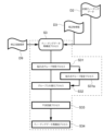
- FIG. 2 is a flowchart of a teaching data creation system for the welding robot of FIG. 1
- FIG. 3 is a flow chart showing the teaching data import process of FIG. 2
- FIG. 4 is a diagram showing an input screen for the teaching data import process of FIG. 3
- FIG. 3 is a flow chart showing the weld distortion reduction process of FIG. 2
- 6 is a flow chart showing the eigendeformation prediction system of FIG. 5
- 6 is weld distortion data predicted in the weld distortion reduction process of FIG. 5
- FIG. 3 is a flow chart showing the teaching data reconstruction process of FIG. 2;
- FIG. 3 is an explanatory diagram showing initial teaching data in FIG. 2;
- FIG. 10 is an explanatory diagram showing teaching data modified from the initial teaching data of FIG. 9;
- FIG. 5 is a flowchart illustrating a teaching data reconstruction process according to another embodiment of the invention.
- FIG. 1 is a diagram showing a schematic configuration of a welding robot and members to be welded according to an embodiment of the present invention.
- the horizontal direction in FIG. 1 is called the X direction
- the vertical direction is called the Z direction
- the direction perpendicular to the X direction and the Z direction front and back directions of the paper surface
- a member 100 to be welded shown in FIG. 1 is a plate-shaped member extending on both sides in the X direction in FIG. 1, and has a convex portion 102 protruding upward in the Z direction substantially at the center in the X direction.
- the member 100 is placed on top of a flat rectangular parallelepiped pedestal 110, and both the left and right ends in the X direction are held and fixed by jigs 112a and 112b such as vices, respectively.
- cylindrical members 104a and 104b extending upward in the Z direction are arranged on both left and right sides of the convex portion 102 in the X direction.
- the cylindrical members 104a and 104b and the member 100 are sandwiched and fixed by jigs 114a and 114b such as vices, respectively.
- the member 100 and the cylindrical members 104a and 104b are welded together by a substantially arc-shaped welding line L1 provided between the member 100 and the cylindrical member 104a, and provided between the member 100 and the cylindrical member 104b. It is configured to be manufactured as a welded structure 120 by welding along a generally arc-shaped welding line L2.
- the member 100 and the cylindrical members 104a and 104b described above are welded by a welding robot 200 arranged adjacently.
- the welding robot 200 is arranged on the upper surface of a flat rectangular parallelepiped pedestal 210 and has a plurality of rotatable joints.
- a first joint 212b of the welding robot 200 that rotates around a first axis 212a extending in the Z direction is attached to the upper surface of the base 210 .
- One end of a first link 212c of the welding robot 200 extending in the Z direction is attached to the first joint 212b.
- a second joint 214b of the welding robot 200 rotating around a second axis 214a extending in the Y direction is attached to the other end of the first link 212c.
- One end of a beam-shaped second link 214c of the welding robot 200 is attached to the second joint 214b.
- a third joint 216b of the welding robot 200 rotating around a third axis 216a extending in the Y direction is attached to the other end of the second link 214c.
- One end of a beam-shaped third link 216c of the welding robot 200 is attached to the third joint 216b.
- a fourth joint 218b of the welding robot 200 rotating around a fourth axis 218a extending in the Y direction is attached to the other end of the third link 216c.
- a welding torch 220 of the welding robot 200 extending like a rod is attached to the fourth joint 218b.
- the welding robot 200 described above is configured to be controlled by a computer 300 located outside.
- the operations of the welding robot 200 such as the rotation of the first joint 212b, the second joint 214b, the third joint 216b, and the fourth joint 218b, and the activation of the welding torch 220, are controlled by the robot CAM software input from the computer 300. 320.
- the computer 300 includes a central processing unit 311, an input device 312 such as a keyboard for inputting data necessary for executing a teaching data creation system, which will be described later, and an instruction to start the welding robot 200, and the results of the teaching data creation system.
- a display device 313 such as a display for displaying etc.
- a storage device 314 such as a memory for storing a program for executing the teaching data creation system
- a robot CAM software 320 created by the teaching data creation system. It has an output device 315 for converting it into a specific format file and outputting it to the robot CAM software 320 .
- the central processing unit 311 controls the input device 312, the display device 313, the output device 315, and the welding robot 200, and is configured to be able to access the storage device 314.
- the information input via the input device 312 and the storage device The program and data recorded in 314 are used to execute the teaching data creation system.
- FIG. 2 is a flowchart of a teaching data creation system for welding robot 200 in FIG.
- the teaching data creation system 400 inputs the initial robot CAM software 320a, which is preset in the welding robot 200, into the teaching data acquisition process S1 before executing the teaching data creation system 400.
- this teaching data acquisition process S1 three-dimensional data of the member 100 to be welded and the cylindrical members 104a and 104b, jigs for fixing the member 100 and the cylindrical members 104a and 104b are input via the input device 312 of the computer 300.
- 3D data of 112a, 112b, 114a, 114b and 3D data of welding robot 200 are input.
- the teaching data acquisition process S1 is passed when welding torch 220 of welding robot 200 performs welding on a plurality of welding lines L1 and L2 provided between member 100 and cylindrical members 104a and 104b.
- the above-described teaching data acquisition process S1 stores initial welding order information D1 including the initial welding order, welding instruction points, initial welding order, avoidance instruction points, initial avoidance order, and welding groups in accordance with the above-described input information.
- initial teaching data D2 peripheral object information D3 determined according to three-dimensional data of member 100, cylindrical members 104a, 104b, and jigs 112a, 112b, 114a, 114b, positions and shapes of welding lines L1, L2, and the initial It is configured to output a welding position D4, a welding condition D5, and welding order information D6 which are determined according to the welding order information D1.
- the teaching data creation system 400 inputs the initial welding order information D1 described above to the welding deformation reduction process S2.
- This welding deformation reduction process S2 is configured to be connected to an inherent deformation prediction system S5 that predicts the welding deformation of the entire structure by FEM analysis using the inherent deformation data described in Patent Document 1, for example.
- the inherent deformation prediction system S5 is configured to calculate the welding deformation prediction result D7 of the member 100 and the cylindrical members 104a and 104b by inputting the welding position D4, the welding condition D5, and the welding order information D6. It is The calculated welding deformation prediction result D7 is input to the deformation amount evaluation process S6 and recorded in the storage device 314 of the computer 300 as the welding deformation prediction result D7 for the welding order information D6.
- the deformation amount evaluation process S6 described above sends an instruction to change the welding order from the initial welding order to the welding deformation reduction process S2.
- the welding deformation reduction process S2 changes the order of the plurality of welding groups in which the welding instruction points and the initial welding order are arranged for each of the plurality of weld lines L1 and L2. By permuting, a weld group change order D8 is obtained.
- the welding deformation reduction process S2 inputs the above-described welding group change order D8 to the inherent deformation prediction system S5 to calculate a welding deformation prediction result D7.
- the welding deformation reduction process S2 and the inherent deformation prediction system S5 repeat the calculation of the welding deformation prediction result D7 for each welding group change order D8.
- the welding group change order D8 having a smaller welding deformation prediction result D7 than the initial welding order is selected as the corrected welding order D9 from among the prediction results D7.
- the teaching data creation system 400 inputs the above-described initial teaching data D2, peripheral object information D3, and corrected welding order D9 to the teaching data reconstruction process S3.
- the corrected welding order D9 the order of the plurality of welding groups in which the welding instruction points and the initial welding order are grouped for each of the plurality of welding lines L1 and L2 is changed, and the member 100 and the cylinder It is configured to reconstruct teaching data that reduces the welding deformation of the members 104a and 104b.
- the teaching data reconstruction process S3 causes the welding robot 200 to interfere with the member 100, the cylindrical members 104a, 104b, and the jigs 112a, 112b, 114a, 114b based on the surrounding object information D3. Adjust avoidance points and initial avoidance order so that it does not occur.
- the teaching data creation system 400 inputs the teaching data reconstructed in the teaching data reconstruction process S3 to the teaching data output process S4.
- the teaching data described above is used as the robot CAM software 320 for driving the first joint 212b, the second joint 214b, the third joint 216b, the fourth joint 218b, and the welding torch 220 of the welding robot 200.
- FIG. 3 is a flow chart showing the teaching data import process S1 of FIG.
- the teaching data creation system 400 is configured to capture information about the periphery of the member 100 to be welded when the initial robot CAM software 320a is input to the teaching data capture process S1.
- a welding order fetching process S12 configured to fetch a plurality of weld groups grouped by L2 is operated.
- the teaching data creation system 400 displays on the computer 300 an input screen for importing information on the periphery of the member 100 to be welded, welding instruction points, initial welding order, avoidance instruction points, initial avoidance order, and welding group. Displayed on device 313 .
- FIG. 4 is a diagram showing an input screen for the teaching data import process S1 in FIG.
- a shape capturing screen W11 configured to show information about the periphery of the member 100 to be welded is displayed on the left side of the input screen W1, and on the right side of the input screen W1,
- a welding order capture screen W12 configured to show welding instruction points, initial welding order, avoidance instruction points, initial avoidance order, and welding groups is displayed.
- the storage device 314 of the computer 300 stores three-dimensional data of the member 100 to be welded and the cylindrical members 104a and 104b, jigs 112a, 112b, 114a and 114b for fixing the member 100 and the cylindrical members 104a and 104b.
- three-dimensional data of the welding robot 200, and the welding torch 220 of the welding robot 200 performs welding on a plurality of welding lines L1 and L2 provided between the member 100 and the cylindrical members 104a and 104b.
- a plurality of welding instruction points through which welding robot 200 passes an initial welding order followed when welding robot 200 passes the welding instruction points, member 100 and cylindrical member 100 when welding robot 200 moves outside of a plurality of weld lines L1, L2; 104a, 104b and jigs 112a, 112b, 114a, 114b, an initial avoidance order to follow when the welding robot 200 passes the avoidance instruction points, and a plurality of welding instruction points and initial welding orders. are recorded in advance.
- a selection button W13 configured to allow selection of the information recorded in the storage device 314 is displayed below the welding order import screen W12.
- 3D data of the member 100 and the cylindrical members 104a and 104b selected by pressing the selection button W13, jigs 112a, 112b and 114a for fixing the member 100 and the cylindrical members 104a and 104b are displayed on the shape import screen W11. , 114b and a plan view and a front view of the welding robot 200 (not shown) are displayed.
- the welding order import screen W12 displays initial teaching data including a plurality of welding instruction points selected by pressing the selection button W13, an initial welding order, avoidance instruction points, an initial avoidance order, and a plurality of welding groups. D2 is displayed.
- FIG. 9 is an explanatory diagram showing the initial teaching data D2 of FIG.
- the tip of the welding torch 220 is positioned at the avoidance instruction point P0.
- the avoidance instruction point P0 is set at a position away from the member 100 and the cylindrical members 104a and 104b in the Y direction so as not to interfere with the member 100, the cylindrical members 104a and 104b and the jigs 112a, 112b, 114a and 114b. It is
- the tip of the welding torch 220 moves from the avoidance instruction point P0 to the avoidance instruction point P1.
- the avoidance instruction point P1 is separated from the member 100 and the cylindrical members 104a and 104b in the Y direction so as not to interfere with the member 100, the cylindrical members 104a and 104b, and the jigs 112a, 112b, 114a and 114b. In terms of direction, it is set at a position closer to the member 100 and the cylindrical members 104a and 104b than the avoidance instruction point P0.
- the tip of the welding torch 220 sequentially passes through the welding instruction points P2 to P5 from the avoidance instruction point P1.
- the welding indication points P2 to P5 are set at positions on a substantially arc-shaped welding line L1 provided between the member 100 and the cylindrical member 104a. Therefore, the tip of the welding torch 220 moves along the substantially arc-shaped welding line L1 when passing through the welding indication points P2 to P5 in order.
- welding is performed along welding line L1.
- welding indication point P6 is set at a position on the right side in the X direction from the welding indication point P5 as the end of welding on the weld line L1.
- This avoidance instruction point P7 is set at a position away from the member 100 and the cylindrical members 104a and 104b in the Y direction so as not to interfere with the member 100, the cylindrical members 104a and 104b and the jigs 112a, 112b, 114a and 114b. It is
- the tip of the welding torch 220 moves from the avoidance instruction point P7 to the avoidance instruction point P8.
- the avoidance instruction point P8 is positioned further in the Y direction from the member 100 and the columnar members 104a and 104b than the avoidance instruction point P7 so as not to interfere with the member 100, the columnar members 104a and 104b, and the jigs 112a, 112b, 114a and 114b. It is set at a position on the right side of the avoidance instruction point P7 in the X direction.
- the avoidance instruction point P9 is separated from the member 100 and the cylindrical members 104a and 104b in the Y direction so as not to interfere with the member 100, the cylindrical members 104a and 104b, and the jigs 112a, 112b, 114a and 114b. In terms of direction, it is set at a position closer to the member 100 and the cylindrical members 104a and 104b than the avoidance instruction point P8 and to the right of the avoidance instruction point P8 in the X direction.
- the tip of the welding torch 220 sequentially passes through the welding instruction points P10 to P13 from the avoidance instruction point P9.
- the welding indication points P10 to P13 are set at positions on a substantially arc-shaped welding line L2 provided between the member 100 and the cylindrical member 104b. Therefore, the tip of the welding torch 220 moves along the substantially arc-shaped welding line L2 when passing through the welding indication points P10 to P13 in order.
- welding is performed along welding line L2.
- This welding indication point P6 is set at a position on the right side in the X direction from the welding indication point P13 as the end of welding on the weld line L2.
- This avoidance instruction point P15 is set at a position away from the member 100 and the cylindrical members 104a and 104b in the Y direction so as not to interfere with the member 100, the cylindrical members 104a and 104b and the jigs 112a, 112b, 114a and 114b. It is
- the avoidance instruction point P16 is set at a position on the right side of the avoidance instruction point P15 in the X direction so as not to interfere with the member 100, the cylindrical members 104a, 104b, and the jigs 112a, 112b, 114a, 114b.
- the initial welding order is such that the tip of welding torch 220 sequentially passes from avoidance instruction point P1 through welding instruction points P2 to P5 set at positions on weld line L1, and then avoidance instruction is started from welding instruction point P6.
- the welding instruction point P14 to the avoidance instruction point P15 are passed. and a second welding order moving to .
- the initial avoidance order includes a first avoidance order in which the tip of welding torch 220 moves from avoidance instruction point P0 to avoidance instruction point P1, and a second avoidance order in which the tip moves from avoidance instruction point P7 to avoidance instruction point P9. and a third avoidance order moving from the avoidance instruction point P15 to the avoidance instruction point P16.
- the welding instruction points P2 to P6 related to welding on the weld line L1 and the first welding order in which the avoidance instruction point P1 sequentially passes through the welding instruction points P2 to P6 and moves to the avoidance instruction point P7 is the first welding order. Grouped into weld groups. Furthermore, a second welding order in which the welding instruction points P10 to P14 related to welding on the weld line L2 and the welding instruction points P10 to P14 are sequentially passed from the avoidance instruction point P9 to the avoidance instruction point P15 is the second welding order. Grouped into weld groups.
- the initial teaching data D2 includes the welding instruction points P2 to P6 and P10 to 14, the initial welding order including the first welding order and the second welding order, and the avoidance instruction points P0, P1, P7 to An initial avoidance order including P9, P15, P16, a first avoidance order, a second avoidance order, and a third avoidance order, a first weld group, and a second weld group.
- This initial teaching data D2 is displayed on the welding order import screen W12 shown in FIG.
- a first rotation angle ⁇ 1 of the first joint 212b, a second rotation angle ⁇ 2 of the second joint 214b, a third rotation angle ⁇ 3 of the third joint 216b, and a fourth rotation angle ⁇ 4 of the fourth joint 218b are input to reach A rotation angle data screen W14 including is displayed.
- the first rotation angle ⁇ 1 of the first joint 212b, the second rotation angle ⁇ 2 of the second joint 214b, the third rotation angle ⁇ 3 of the third joint 216b, and the fourth rotation angle ⁇ 4 of the fourth joint 218b are set by welding, for example.
- An input button W15 is displayed adjacent to the selection button W13 on the input screen W1 in FIG.
- This input button W15 By pressing this input button W15, three-dimensional data of the member 100 and the cylindrical members 104a and 104b displayed on the shape capturing screen W11, jigs 112a, 112b and 114a for fixing the member 100 and the cylindrical members 104a and 104b, 114b and the three-dimensional data of the welding robot 200 are input to the shape capture process S11, and the welding instruction points P2 to P6, P10 to 14 and the avoidance instruction point P1 displayed on the welding order capture screen W12.
- an initial welding sequence including a second welding sequence, avoidance instruction points P0, P1, P7-P9, P15, P16, a first avoidance sequence moving from avoidance instruction point P0 to avoidance instruction point P1 and from avoidance instruction point P7
- An initial avoidance sequence including a second avoidance sequence moving to the avoidance indication point P9 and a third avoidance sequence moving from the avoidance indication point P15 to the avoidance indication point P16, and the first weld group and the second weld group It is input to the welding order import process S12.
- the welding order acquisition process S12 includes welding instruction points P2 to P6 and P10 to 14, and a first welding order and an avoidance instruction for moving from the avoidance instruction point P1 to the avoidance instruction point P7 through the welding instruction points P2 to P6 in order.
- a second welding order moving from point P9 through welding instruction points P10 to P14 in order to avoidance instruction point P15; avoidance instruction points P0, P1, P7 to P9, P15, P16;
- the welding order capture process S12 also outputs initial welding order information D1 including the initial welding order, the first weld group, the second weld group, and the order of the first weld group and the second weld group. is configured as
- the teaching data creation system 400 operates the welding locus calculation process S13.
- This welding locus calculation process S13 is provided between the member 100 and the cylindrical members 104a and 104b by referring to the three-dimensional data of the member 100 and the cylindrical members 104a and 104b recorded in the storage device 314 of the computer 300. It is configured to calculate the trajectories of the weld lines L1 and L2.
- This welding position search process S14 includes the trajectories of the welding lines L1 and L2 calculated in the welding trajectory calculation process S13, the welding instruction points P2 to P6 and P10 to 14, and the member 100 and the cylinder output from the shape capturing process S11. It is configured to search for a welding position when welding is performed by the welding torch 220 according to three-dimensional data of the members 104a and 104b.
- the teaching data creation system 400 operates the welding condition allocation process S15.
- This welding condition assignment process S15 performs welding positions D4, welding conditions D5, and welding orders according to the welding positions searched in the welding position searching process S14 and the initial welding order information D1 output from the welding order acquisition process S12. It is configured to output information D6.
- FIG. 5 is a flowchart showing the welding deformation reduction process S2 of FIG.
- the teaching data creation system 400 inputs the initial welding order information D1 to the welding deformation reduction process S2. , operates the welding deformation reduction process S2.
- the inherent deformation prediction system S5 connected to the welding deformation reduction process S2 receives the welding position D4, the welding conditions D5, and the welding order information D6 output from the welding condition assignment process S15 of the teaching data acquisition process S1. , a predicted result D7 of welding deformation of the member 100 and the cylindrical members 104a and 104b.
- FIG. 6 is a flow chart showing the unique deformation prediction system S5 of FIG.
- welding lines L1 and L2 provided between the member 100 and the cylindrical members 104a and 104b are extracted according to the welding position D4, the welding conditions D5, and the welding sequence information D6 (step S51).
- step S52 inherent deformation data about weld lines L1 and L2 of the structure 120 used in FEM analysis for predicting welding deformation of the structure 120 obtained by welding the member 100 and the cylindrical members 104a and 104b is calculated.
- step S52 After calculating the inherent deformation data for the weld lines L1 and L2 of the structure 120, the inherent deformation data for the weld lines L1 and L2 are recorded in the storage device 314 of the computer 300 as an inherent deformation calculation result file.
- the structural body 120 is subjected to finite element division from the graphic data of the structural body 120 to create an analytical model.
- the deformation data is applied to calculate the welding deformation of the structure 120 by elastic FEM analysis (step S53).
- the prediction result D7 of the welding deformation of the structure 120 which is the analysis result, is output to the deformation amount evaluation process S6 (step S54).
- the deformation amount evaluation process S6 records the prediction result D7 in the storage device 314 of the computer 300 when the welding deformation prediction result D7 is input. Further, after recording the welding deformation prediction result D7, the deformation amount evaluation process S6 sends an instruction to change the welding order from the initial welding order to the welding deformation reduction process S2.
- An instruction to change the welding order described above from the initial welding order is sent to the GA algorithm solver S21 of the welding deformation reduction process S2.
- the GA algorithm solver S21 uses a genetic algorithm to change the welding order included in the welding order information D6, that is, the order of the welding groups included in the initial welding order information D1. configured to be replaced. For example, after welding in a first welding group including a first welding sequence moving from the avoidance instruction point P1 through the welding instruction points P2 to P6 in order to the avoidance instruction point P7, welding instruction from the avoidance instruction point P9 is performed.
- An initial welding sequence of welding in a second weld group including a second welding sequence sequentially passing through points P10-P14 and moving to avoidance instruction point P15 is performed after welding in the second weld group.
- the order in which the welds are performed in the weld group is permuted.
- the teaching data creation system 400 operates the trial case creation process S22 of the welding deformation reduction process S2.
- This trial case creation process S22 changes the welding order from the initial welding order according to the welding order changed in the GA algorithm solver S21. It is configured to output order D8.
- the inherent deformation prediction system S5 receives the welding group change order D8 output from the trial case creation process S22, recalculates the welding deformation prediction result D7 of the structure 120, and outputs it again to the deformation amount evaluation process S6. It is configured.
- the welding deformation reduction process S2, the inherent deformation prediction system S5, and the deformation amount evaluation process S6 repeat calculating the welding deformation prediction result D7 for each welding group change order D8, and the calculated prediction
- the result D7 is recorded in the storage device 314 of the computer 300 to create a welding deformation data file.
- FIG. 7 shows data of welding deformation predicted in the welding deformation reduction process S2 of FIG.
- the horizontal axis of the data in FIG. 7 indicates the number of trials of the welding group change order D8 output from the trial case creation process S22 of the welding deformation reduction process S2.
- the vertical axis of the data in FIG. 7 indicates the magnitude of the welding deformation prediction result D7 for each welding group change order D8. Therefore, FIG. 7 shows data summarizing the magnitude of the prediction result D7 with respect to the welding group change order D8.
- the deformation amount evaluation process S6 selects from the plurality of welding deformation prediction results D7 recorded in the storage device 314 from the initial welding order. is also configured to select the welding group change order D8 with the smallest welding deformation prediction result D7 as the corrected welding order D9.
- the teaching data creation system 400 operates the cycle time calculation process S23 of the welding deformation reduction process S2 when the deformation amount evaluation process S6 selects the modified welding order D9.
- This cycle time calculation process S23 intervenes in the deformation amount evaluation process S6 to calculate the cycle time of each welding group change order D8.
- the deformation amount evaluation process S6 in the embodiment selects, as the modified welding order D9, the welding group change order D8 in which the cycle time required for welding is smaller than the initial welding order and the welding deformation prediction result D7 is smaller than the initial welding order. is configured as
- FIG. 8 is a flow chart showing the teaching data reconstruction process S3 of FIG.
- the teaching data creation system 400 reconstructs the teaching data from the initial teaching data D2 and the surrounding object information D3 output from the teaching data acquisition process S1 and the corrected welding order D9 selected in the deformation amount evaluation process S6. Input to the process S3 to operate the teaching data reconstruction process S3.
- the teaching data creation system 400 operates the indicated point group reference process S31.
- This instruction point group reference process S31 is based on the initial teaching data D2, and is the first welding order in which the avoidance instruction point P1 shown in FIG. , a second welding group including a second welding order that sequentially passes through the welding instruction points P10 to P14 from the avoidance instruction point P9 to the avoidance instruction point P15, and the first welding It is configured to refer to the order of the group and the second weld group.
- the teaching data creation system 400 refers to the first welding group, the second welding group, and the order of the first welding group and the second welding group.
- the group exchange process S32 is operated. This group exchange process S32 exchanges the order of the plurality of weld groups described above according to a modified welding order D9 that reduces welding deformation of the structure 120 obtained by welding the member 100 and the cylindrical members 104a and 104b.
- the order of performing welding in the first welding group after welding in the second welding group is the modified welding order D9.
- the order of the weld groups is reversed such that the welds in the second weld group are followed by the welds in the first weld group. That is, the order of welding is as follows: after welding in accordance with the second welding order in which the avoidance instruction point P9 passes through the welding instruction points P10 to P14 in order and moves to the avoidance instruction point P15, the welding order from the avoidance instruction point P1 to the welding instruction point P2 is performed. to P6 in order to move to the avoidance instruction point P7.
- the teaching data creation system 400 activates the interference avoidance process S33 when a plurality of welding groups are switched in the group replacement process S32.
- FIG. 10 is an explanatory diagram showing teaching data modified from the initial teaching data of FIG.
- the corrected teaching data shown in FIG. 10 is obtained by the replacement of the plurality of welding groups in the group replacement process S32 described above and the adjustment of the avoidance instruction points P0, P8, P16 and the initial avoidance order in the interference avoidance process S33.
- This modified teaching data moves the tip of the welding torch 220 from the avoidance instruction point P0 to the avoidance instruction point P9 according to the first adjustment avoidance order, and moves from the avoidance instruction point P9 to the welding instruction points P10 to P14. Move in accordance with the second welding order of moving to the avoidance instruction point P15 in order, and move according to the second adjustment avoidance order of moving from the avoidance instruction point P15 to the avoidance instruction point P1 via the avoidance instruction point P8.
- the welding deformation of the structure 120 obtained by welding the member 100 and the cylindrical members 104a and 104b is reduced, and the peripheral objects, that is, the member 100, the cylindrical members 104a and 104b, and the jigs. Interference with tools 112a, 112b, 114a, 114b is avoided.
- the teaching data creation system 400 operates the teaching data reconstruction process S34 when the avoidance instruction points P0, P8, P16 and the initial avoidance order are adjusted.
- This teaching data reconstruction process S34 is configured to reconstruct the modified teaching data described above and output it to the teaching data output process S4.
- this teaching data output process S4 uses the corrected teaching data to drive the first joint 212b, the second joint 214b, the third joint 216b, the fourth joint 218b, and the welding torch 220 of the welding robot 200. is converted into a specific format file of the robot CAM software 320, and the specific format file is output to the robot CAM software 320.
- the teaching data creation system 400 adjusts the order of the first welding group and the second welding group, the avoidance instruction points P0, P8, and P16, and the initial avoidance order, and prepares the teaching data and the teaching data reconstructed in the teaching data reconstruction process S3 are used to reconstruct the first joint 212b, the second joint 214b, the third joint 216b and the fourth joint 218b of the welding robot 200. and a teaching data output process S4 for converting into a format file unique to the robot CAM software 320 for driving the welding torch 220 and outputting the unique format file to the robot CAM software 320.
- the teaching data reconstruction process S3 includes a group exchange process S32 that exchanges the order of the first welding group and the second welding group according to the modified welding order D9 that reduces the welding deformation of the member 100 and the cylindrical members 104a and 104b. and an interference avoidance process S33 for adjusting the avoidance instruction points P0, P8, P16 and the initial avoidance order so that the welding robot 200 does not interfere with the member 100, the cylindrical members 104a, 104b, and the jigs 112a, 112b, 114a, 114b. It is characterized by having
- the order of the first welding group and the second welding group is exchanged so as to reduce the welding deformation of the member 100 and the cylindrical members 104a and 104b, and by the interference avoidance process S33, the welding robot 200
- the avoidance instruction points P0, P8, P16 and the order of avoidance can be adjusted so as to prevent interference between the member 100 and the cylindrical members 104a, 104b and jigs 112a, 112b, 114a, 114b.
- a teaching data creation system 400 that reduces welding deformation and prevents the welding robot 200 from interfering with the member 100, the cylindrical members 104a, 104b, and the jigs 112a, 112b, 114a, 114b, and the teaching data creation system 400 are provided. I can provide a program to run.
- first joint 212b, the second joint 214b, the third joint 216b, the fourth joint 218b, and the welding torch 220 of the welding robot 200 are arranged at the welding instruction points P2 to P6, according to the welding order and movement order included in the teaching data.
- the first rotation angle ⁇ 1, the second rotation angle ⁇ 2, the third rotation angle ⁇ 3, and the fourth rotation angle ⁇ 4 defined by P10 to P14 and the avoidance instruction points P0, P1, P7 to P9, P15, and P16 are reached. drive. Therefore, the welding robot 200 can operate in a position and posture that reduces welding deformation and prevents interference between the member 100 and the cylindrical members 104a, 104b and jigs 112a, 112b, 114a, 114b.
- the calculation of the welding deformation prediction result D7 of the member 100 and the cylindrical members 104a and 104b is repeated for each welding group change order D8 obtained by changing the order of the first welding group and the second welding group.
- the welding group change order D8 in which the prediction result D7 of the welding deformation of the member 100 and the cylindrical members 104a and 104b is smaller than the initial order of the first welding group and the second welding group is the welding group change order D8 of the member 100 and the cylindrical members 104a and 104b.
- this corrected welding order D9 a first welding group and a first welding group in which a plurality of welding instruction points P2 to P6, P10 to P14 and the first and second welding orders are arranged for each of a plurality of welding lines L1, L2.
- the cycle time required for welding is smaller than the initial order of the first welding group and the second welding group, and the welding deformation prediction result D7 of the member 100 and the cylindrical members 104a and 104b is smaller than the initial order.
- Group change order D8 is chosen as modified welding order D9.
- the interference avoidance process S33 of the teaching data reconstruction process S3 is performed when the welding robot 200 moves outside the plurality of welding lines L1 and L2.
- the avoidance instruction points P0, P8 and P16 that are passed through so as not to interfere with 114b and the avoidance order that the welding robot 200 follows when passing through the avoidance instruction points P0, P8 and P16 are adjusted. Therefore, it is possible to provide the teaching data creation system 400 that prevents the welding robot 200 from interfering with the member 100, the cylindrical members 104a, 104b, and the jigs 112a, 112b, 114a, 114b.
- the shape acquisition process S11 and the welding order acquisition process S12 of the teaching data acquisition process S1 include three-dimensional data of the member 100 and the cylindrical members 104a and 104b recorded in the storage device 314 of the computer 300, and 3D data of jigs 112a, 112b, 114a, 114b for fixing cylindrical members 104a, 104b; 3D data of welding robot 200; A plurality of welding instruction points P2 to P6, P10 to P14 through which welding is performed on a plurality of welding lines L1, L2 provided in the welding robot 200, the welding instruction points P2 to P6, P10 to P14.
- a plurality of cameras are connected to the computer 300 as the input device 312 to photograph the member 100 and the cylindrical members 104a and 104b, and the jigs 112a, 112b, 114a and 114b for fixing the member 100 and the cylindrical members 104a and 104b. Accordingly, three-dimensional data captured by the shape capturing process S11 and the welding order capturing process S12 may be input.
- a VR device imitating the welding torch 220 is connected to the computer 300 as an input device 312, and the user moves the VR device to obtain a plurality of welding instruction points P2 to P6, P10 to P14, the initial welding order, Avoidance points P0, P1, P7-P9, P15, P16, initial avoidance order, and first and second weld groups may be captured.
- the interference avoidance process S33 of the teaching data reconstruction process S3 includes the first avoidance order of moving from the avoidance instruction point P0 to the avoidance instruction point P1, and the first avoidance order of moving from the avoidance instruction point P0 to the avoidance instruction point P9. 1, and the second avoidance order moving from the avoidance instruction point P7 to the avoidance instruction point P9 is changed to the second avoidance order moving from the avoidance instruction point P15 to the avoidance instruction point P1 via the avoidance instruction point P8. 2, and the third avoidance order moving from the avoidance instruction point P15 to the avoidance instruction point P16 is changed to the third adjusted avoidance order moving from the avoidance instruction point P7 to the avoidance instruction point P16.
- the avoidance instruction points P0, P8, P16 and the order of avoidance are adjusted, but the avoidance instruction points P0, P8, P16 and the order of avoidance may be adjusted by other methods.
- the avoidance points P0, P8, P16 and the order of avoidance may be adjusted by changing the three-dimensional coordinates of the avoidance points P0, P8, P16.
- the avoidance points and the order of avoidance may be adjusted by adding new avoidance points.
- the avoidance instruction points are preferably configured as the coordinate trajectory of the tip of the welding torch 220, respectively.
- the teaching data output process S4 is configured to convert teaching data into a format file unique to the robot CAM software 320 and output the unique format file to the robot CAM software 320. may be configured to directly output the specific format file to welding robot 200 . Alternatively, the teaching data output process S4 is configured to convert the teaching data into another format acceptable by the robot CAM software 320 and output it to the robot CAM software 320 or the welding robot 200. good too.
- the first joint 212b, the second joint 214b, the third joint 216b, the fourth joint 218b, and the welding torch 220 of the welding robot 200 are connected to the welding instruction points P2 to P6, P10 to P14 and the avoidance instruction points P0, Driving is performed so as to reach the first rotation angle ⁇ 1, the second rotation angle ⁇ 2, the third rotation angle ⁇ 3, and the fourth rotation angle ⁇ 4 determined by P1, P7 to P9, P15, and P16.
- the robot may be driven to reach the three-dimensional coordinates.
- the welding order acquisition process S12 of the teaching data acquisition process S1 is configured to acquire a plurality of welding groups in which the welding instruction points and the initial welding order D1 are arranged for each of the plurality of weld lines L1 and L2. but may be configured not to include this weld group.
- FIG. 11 is a flow chart showing the teaching data reconstruction process S3 according to another embodiment of the present invention.
- the teaching data creation system 400 operates the instruction point group setting process S31a after operating the instruction point group reference process S31 and before operating the group exchange process S32. You may let This instruction point group setting process S31a is performed, for example, when the first welding group and the second welding group are not set for each of the welding instruction points P2 to P6 and P10 to P14 in the welding order acquisition process S12. , the welding indicated points P2 to P6 set on the welding line L1 are assigned to a temporary first welding group, and the welding indicated points P10 to P14 set on the welding line L2 are assigned to a temporary second welding group. It is configured to be automatically sorted and set respectively. On the other hand, when the first welding group and the second welding group are set in the welding order acquisition process S12, similarly to FIG. , operates the group exchange process S32.
- the instruction point group setting process S31a is configured to add any of the avoidance instruction points before and after the provisional first welding group and the provisional second welding group automatically set as described above.
- the instruction point group setting process S31a adds the avoidance instruction points P1 and P7 set before and after the welding instruction points P2 to P6 in the first welding order to the temporary first welding group.
- the avoidance instruction points P9 and P15 set before and after the welding instruction points P10 to P14 are added to the temporary second welding group, thereby forming the second welding group.
- the instruction point group setting process S31a extracts adjacent avoidance instruction points within a predetermined distance from the welding instruction points P2 and P6, which are the start and end points of the temporary first welding group, and creates a temporary first welding group.
- avoidance instruction points within a specified distance from the welding instruction points P10 and P14, which are the start and end points of the temporary second welding group are extracted to perform the temporary second welding.
- Adding to the group may be configured to result in a second weld group.
- the indicated point group setting process S31a described above is performed by the user's operation via the input device 312 even when the first welding group and the second welding group are set in the welding order acquisition process S12. may be configured to operate. According to this instruction point group setting process S31a, in the welding order acquisition process S12, another additional welding group can be set for the preset welding group, and the teaching data can be reconfigured.
Landscapes
- Engineering & Computer Science (AREA)
- Physics & Mathematics (AREA)
- Mechanical Engineering (AREA)
- General Physics & Mathematics (AREA)
- Automation & Control Theory (AREA)
- Plasma & Fusion (AREA)
- Robotics (AREA)
- Geometry (AREA)
- Human Computer Interaction (AREA)
- Manufacturing & Machinery (AREA)
- Numerical Control (AREA)
- Manipulator (AREA)
Abstract
本発明のティーチングデータ作成システム(400)は、溶接順序、回避指示点(P0,P1,P7~P9,P15,P16)、及び回避順序を調整して、ティーチングデータを再構成するティーチングデータ再構成プロセス(S3)を備える。ティーチングデータ再構成プロセス(S3)は、部材(100,104a,104b)の溶接変形を低減させる修正溶接順序(D9)に従って、複数の溶接グループの順序を入れ替えるグループ入れ替えプロセス(S32)を備える。
Description
本発明は、ロボットティーチングデータ作成システム及びプログラムに関する。
複数の部材を溶接して構造体を製造する場合、回転可能なジョイントを備える溶接ロボットが用いられることがある。
上述の溶接ロボットは、予め決められたティーチングデータに基づいてジョイントを駆動させることにより、所望の動作を行うように構成されている。このティーチングデータは、溶接ロボットを動作させるジョイントの回転角度を含んでおり、例えば溶接ロボットが構造体や構造体を固定するための治具と干渉することなく、且つ溶接に必要なサイクルタイムが最小となる動作ができるように決められる。
上述のように決められたティーチングデータに基づいて溶接を行うことによって、溶接の品質が一定に保たれると共に、溶接に必要なサイクルタイムを削減できる。一方、溶接ロボットは溶接中の微調整を行うことが難しいため、溶接ロボットによる溶接は、手作業による溶接に比べて、溶接によって生じる構造体の変形、すなわち溶接変形が大きくなるという課題がある。
例えば特許文献1には、固有変形データを用いて構造体全体の溶接変形をFEM解析によって予測する溶接変形予測システム及び溶接変形予測プログラムが開示されている。
また、溶接ロボットによる溶接を行う場合、溶接が行われる部材に設けられている複数の溶接線に対して溶接を行うときの順序、すなわち溶接順序に応じて、構造体全体の溶接変形が変化することが知られている。
したがって、上述のティーチングデータは、溶接変形が大きくならないように、構造体全体の溶接変形を溶接順序ごとに予測して、溶接変形が最も小さい溶接順序を組み込まれる必要がある。
また、ティーチングデータは、溶接順序だけではなく、例えば溶接ロボットのアームの先端に設けられている溶接トーチが複数の溶接線の外部を移動するときの順序を含む。溶接ロボットは、この順序に従って動作するとき、溶接が行われる部材、及び該部材を固定するための治具などの周辺物と干渉する虞がある。
したがって、上述のティーチングデータは、溶接ロボットが部材及び周辺物と干渉しないように構成される必要がある。
そこで、本発明は、溶接変形を低減すると共に、溶接ロボットが部材及び周辺物と干渉することを防ぐティーチングデータ作成システム及びプログラムを提供することを課題とする。
前記課題を解決するため、本発明は、次のように構成したことを特徴とする。
まず、本願の請求項1に記載の発明は、溶接ロボット用のティーチングデータ作成システムであって、
前記ティーチングデータは、
前記溶接ロボットが、所定の部材に設けられている複数の溶接線に対して溶接を行うときに通過する複数の溶接指示点と、
前記溶接ロボットが前記溶接指示点を通過するときに従う溶接順序と、
前記溶接ロボットが前記複数の溶接線の外部を移動するとき、前記部材及び前記部材の周辺物と干渉しないように通過する回避指示点と、
前記溶接ロボットが前記回避指示点を通過するときに従う回避順序とを含んでおり、
前記ティーチングデータ作成システムは、
前記溶接順序、前記回避指示点、及び前記回避順序を調整して、前記ティーチングデータを再構成するティーチングデータ再構成プロセスと、
前記ティーチングデータ再構成プロセスにおいて再構成された前記ティーチングデータを、前記溶接ロボットを動作させるためのソフトウェアが受付可能な形式に変換して、前記溶接ロボットまたは前記ソフトウェアに向けて出力するティーチングデータ出力プロセスとを備えており、
前記ティーチングデータ再構成プロセスは、
前記溶接指示点及び前記溶接順序が前記複数の溶接線ごとにまとめられている複数の溶接グループを参照する指示点グループ参照プロセスと、
前記部材の溶接変形を低減させる修正溶接順序に従って、前記複数の溶接グループの順序を入れ替えるグループ入れ替えプロセスを備えることを特徴とする。
前記ティーチングデータは、
前記溶接ロボットが、所定の部材に設けられている複数の溶接線に対して溶接を行うときに通過する複数の溶接指示点と、
前記溶接ロボットが前記溶接指示点を通過するときに従う溶接順序と、
前記溶接ロボットが前記複数の溶接線の外部を移動するとき、前記部材及び前記部材の周辺物と干渉しないように通過する回避指示点と、
前記溶接ロボットが前記回避指示点を通過するときに従う回避順序とを含んでおり、
前記ティーチングデータ作成システムは、
前記溶接順序、前記回避指示点、及び前記回避順序を調整して、前記ティーチングデータを再構成するティーチングデータ再構成プロセスと、
前記ティーチングデータ再構成プロセスにおいて再構成された前記ティーチングデータを、前記溶接ロボットを動作させるためのソフトウェアが受付可能な形式に変換して、前記溶接ロボットまたは前記ソフトウェアに向けて出力するティーチングデータ出力プロセスとを備えており、
前記ティーチングデータ再構成プロセスは、
前記溶接指示点及び前記溶接順序が前記複数の溶接線ごとにまとめられている複数の溶接グループを参照する指示点グループ参照プロセスと、
前記部材の溶接変形を低減させる修正溶接順序に従って、前記複数の溶接グループの順序を入れ替えるグループ入れ替えプロセスを備えることを特徴とする。
また、請求項2に記載の発明は、前記請求項1の発明において、前記ティーチングデータ再構成プロセスは、
前記溶接ロボットが前記部材及び前記周辺物と干渉しないように、前記回避指示点と前記回避順序を調整する干渉回避プロセスを備えることを特徴とする。
前記溶接ロボットが前記部材及び前記周辺物と干渉しないように、前記回避指示点と前記回避順序を調整する干渉回避プロセスを備えることを特徴とする。
また、請求項3に記載の発明は、前記請求項1または請求項2の発明において、前記溶接ロボットは回転可能なジョイントを備えており、
前記溶接指示点と前記回避指示点は、それぞれ、前記溶接ロボットの前記ジョイントの目標値を含むことを特徴とする。
前記溶接指示点と前記回避指示点は、それぞれ、前記溶接ロボットの前記ジョイントの目標値を含むことを特徴とする。
また、請求項4に記載の発明は、前記請求項1から請求項3のいずれか1項の発明において、前記ティーチングデータ作成システムは、前記複数の溶接グループが予め設定されていない場合、前記複数の溶接線ごとに前記複数の溶接指示点を自動的に振り分けることによって複数の仮の溶接グループを設定して、前記複数の仮の溶接グループの始点と終点の近傍に位置する前記回避指示点を前記複数の仮の溶接グループに追加することによって前記複数の溶接グループを設定する指示点グループ設定プロセスを備えることを特徴とする。
また、請求項5に記載の発明は、前記請求項1から請求項3のいずれか1項の発明において、前記ティーチングデータ作成システムは、前記複数の溶接グループが予め設定されている場合、前記複数の溶接線の一部に対して前記複数の溶接指示点の一部を振り分けることによって複数の仮の追加溶接グループを設定して、前記複数の仮の追加溶接グループの始点と終点の近傍に位置する前記回避指示点を前記複数の仮の追加溶接グループに追加することによって前記複数の追加溶接グループを設定する指示点グループ設定プロセスを備えることを特徴とする。
また、請求項6に記載の発明は、前記請求項1から請求項5のいずれか1項の発明において、前記ティーチングデータ作成システムは、前記修正溶接順序を出力する溶接変形低減プロセスを備えており、
前記溶接変形低減プロセスでは、前記複数の溶接グループの順序を入れ替えることによって得られる溶接グループ変更順序ごとに前記部材の前記溶接変形の予測結果を算出することを繰り返して、前記複数の溶接グループの初期順序よりも前記部材の前記溶接変形の予測結果が小さい前記溶接グループ変更順序が前記修正溶接順序として選ばれることを特徴とする。
前記溶接変形低減プロセスでは、前記複数の溶接グループの順序を入れ替えることによって得られる溶接グループ変更順序ごとに前記部材の前記溶接変形の予測結果を算出することを繰り返して、前記複数の溶接グループの初期順序よりも前記部材の前記溶接変形の予測結果が小さい前記溶接グループ変更順序が前記修正溶接順序として選ばれることを特徴とする。
また、請求項7に記載の発明は、前記請求項6の発明において、前記溶接変形低減プロセスは、前記初期順序よりも溶接に必要なサイクルタイムが小さく、且つ前記初期順序よりも前記部材の前記溶接変形の予測結果が小さい前記溶接グループ変更順序を前記修正溶接順序として選ぶことを特徴とする。
また、請求項8に記載の発明は、前記請求項1から請求項7のいずれか1項に記載の発明において、前記周辺物は、前記部材を固定するための治具を含むことを特徴とする。
さらに、請求項9に記載の発明は、溶接ロボット用のティーチングデータ作成プログラムであって、
前記ティーチングデータは、
前記溶接ロボットが、所定の部材に設けられている複数の溶接線に対して溶接を行うときに通過する複数の溶接指示点と、
前記溶接ロボットが前記溶接指示点を通過するときに従う溶接順序と、
前記溶接ロボットが前記複数の溶接線の外部を移動するとき、前記部材及び前記部材の周辺物と干渉しないように通過する回避指示点と、
前記溶接ロボットが前記回避指示点を通過するときに従う回避順序とを含んでおり、
前記ティーチングデータ作成プログラムは、
前記溶接順序、前記回避指示点、及び前記回避順序を調整して、前記ティーチングデータを再構成するティーチングデータ再構成プロセスと、
前記ティーチングデータ再構成プロセスにおいて再構成された前記ティーチングデータを、前記溶接ロボットを動作させるためのソフトウェアが受付可能な形式に変換して、前記溶接ロボットまたは前記ソフトウェアに向けて出力するティーチングデータ出力プロセスとを備えており、
前記ティーチングデータ再構成プロセスは、
前記溶接指示点及び前記溶接順序が前記複数の溶接線ごとにまとめられている複数の溶接グループを参照する指示点グループ参照プロセスと、
前記部材の溶接変形を低減させる修正溶接順序に従って、前記複数の溶接グループの順序を入れ替えるグループ入れ替えプロセスを備えることを特徴とする。
前記ティーチングデータは、
前記溶接ロボットが、所定の部材に設けられている複数の溶接線に対して溶接を行うときに通過する複数の溶接指示点と、
前記溶接ロボットが前記溶接指示点を通過するときに従う溶接順序と、
前記溶接ロボットが前記複数の溶接線の外部を移動するとき、前記部材及び前記部材の周辺物と干渉しないように通過する回避指示点と、
前記溶接ロボットが前記回避指示点を通過するときに従う回避順序とを含んでおり、
前記ティーチングデータ作成プログラムは、
前記溶接順序、前記回避指示点、及び前記回避順序を調整して、前記ティーチングデータを再構成するティーチングデータ再構成プロセスと、
前記ティーチングデータ再構成プロセスにおいて再構成された前記ティーチングデータを、前記溶接ロボットを動作させるためのソフトウェアが受付可能な形式に変換して、前記溶接ロボットまたは前記ソフトウェアに向けて出力するティーチングデータ出力プロセスとを備えており、
前記ティーチングデータ再構成プロセスは、
前記溶接指示点及び前記溶接順序が前記複数の溶接線ごとにまとめられている複数の溶接グループを参照する指示点グループ参照プロセスと、
前記部材の溶接変形を低減させる修正溶接順序に従って、前記複数の溶接グループの順序を入れ替えるグループ入れ替えプロセスを備えることを特徴とする。
以上の構成により、本願各請求項の発明によれば、次の効果が得られる。
まず、本願の請求項1に記載の発明によれば、ティーチングデータ作成システムのティーチングデータ再構成プロセスは、部材の溶接変形を低減させる修正溶接順序に従って、所定の部材に設けられている複数の溶接線に対して溶接を行うときに通過する複数の溶接指示点と、溶接ロボットが溶接指示点を通過するときに従う溶接順序とが複数の溶接線ごとにまとめられている複数の溶接グループの順序を入れ替えるグループ入れ替えプロセスを備える。したがって、溶接変形を低減すると共に、溶接ロボットが部材及び周辺物と干渉することを防ぐティーチングデータ作成システムを提供できる。
また、請求項2に記載の発明によれば、ティーチングデータ作成システムのティーチングデータ再構成プロセスは、溶接ロボットが複数の溶接線の外部を移動するとき、部材及び周辺物と干渉しないように通過する回避指示点と、溶接ロボットが回避指示点を通過するときに従う回避順序とを調整する干渉回避プロセスを備える。したがって、溶接変形を低減すると共に、溶接ロボットが部材及び周辺物と干渉することをより防ぐティーチングデータ作成システムを提供できる。
また、請求項3に記載の発明によれば、溶接ロボットは回転可能なジョイントを備える。また、溶接指示点と回避指示点は、それぞれ、溶接ロボットのジョイントの目標値を含む。したがって、溶接ロボットのジョイントは、溶接順序と回避順序に従って、ティーチングデータに含まれる溶接指示点と回避指示点に定められている回転角度や3次元座標などの目標値に達するように駆動するため、溶接ロボットは、溶接変形を低減すると共に、部材及び周辺物と干渉することを防ぐような位置と姿勢で動作できる。
また、請求項4に記載の発明によれば、ティーチングデータ作成システムは、複数の溶接グループが予め設定されていない場合、複数の溶接線ごとに複数の溶接指示点を自動的に振り分けることによって複数の仮の溶接グループを設定して、複数の仮の溶接グループの始点と終点の近傍に位置する回避指示点を複数の仮の溶接グループに追加することによって複数の溶接グループを設定する指示点グループ設定プロセスを備える。したがって、溶接グループを予め設定することなく、ティーチングデータを作成することができる。
また、請求項5に記載の発明によれば、ティーチングデータ作成システムは、複数の溶接グループが予め設定されている場合、複数の溶接線の一部に対して複数の溶接指示点の一部を振り分けることによって複数の仮の追加溶接グループを設定して、複数の仮の追加溶接グループの始点と終点の近傍に位置する回避指示点を複数の仮の追加溶接グループに追加することによって複数の追加溶接グループを設定する指示点グループ設定プロセスを備える。したがって、予め設定されている溶接グループと、新たに設定される追加溶接グループとにより、ティーチングデータを作成することができる。
また、請求項6に記載の発明によれば、複数の溶接グループの順序を入れ替えることによって得られる溶接グループ変更順序ごとに部材の溶接変形の予測結果を算出することを繰り返して、複数の溶接グループの初期順序よりも部材の溶接変形の予測結果が小さい溶接グループ変更順序が修正溶接順序として選ばれる。この修正溶接順序に従って、複数の溶接指示点と溶接順序とが複数の溶接線ごとにまとめられている複数の溶接グループの順序を入れ替えることにより、部材の溶接変形を低減できる。
また、請求項7に記載の発明によれば、複数の溶接グループの初期順序よりも溶接に必要なサイクルタイムが小さく、且つ初期順序よりも部材の溶接変形の予測結果が小さい溶接グループ変更順序が修正溶接順序として選ばれる。この修正溶接順序に従って、複数の溶接指示点と溶接順序とが複数の溶接線ごとにまとめられている複数の溶接グループの順序を入れ替えることにより、部材の溶接変形を低減すると共に、溶接に必要なサイクルタイムも低減できる。
また、請求項8に記載の発明によれば、ティーチングデータ作成システムにおいて、ティーチングデータ再構成プロセスの干渉回避プロセスは、溶接ロボットが複数の溶接線の外部を移動するとき、部材及び治具と干渉しないように通過する回避指示点と、溶接ロボットが回避指示点を通過するときに従う回避順序とを調整する。したがって、溶接ロボットが部材及び治具と干渉することを防ぐティーチングデータ作成システムを提供できる。
さらに、請求項9に記載の発明によれば、ティーチングデータ作成プログラムのティーチングデータ再構成プロセスは、部材の溶接変形を低減させる修正溶接順序に従って、所定の部材に設けられている複数の溶接線に対して溶接を行うときに通過する複数の溶接指示点と、溶接ロボットが溶接指示点を通過するときに従う溶接順序とが複数の溶接線ごとにまとめられている複数の溶接グループの順序を入れ替えるグループ入れ替えプロセスを備える。したがって、溶接変形を低減すると共に、溶接ロボットが部材及び周辺物と干渉することを防ぐティーチングデータ作成プログラムを提供できる。
以下、本発明の実施形態について添付図面を参照しながら説明する。
図1は、本発明の実施形態に係る溶接ロボット、及び溶接が行われる部材の概略構成を示す図である。以下の説明では、図1における左右方向をX方向、上下方向をZ方向、X方向とZ方向に直交する方向(紙面の表裏方向)をY方向という。
図1に示す溶接が行われる部材100は、図1におけるX方向の左右両側に延びる板状部材であり、X方向における略中央においてZ方向の上方に向けて突出する凸部102を有する。また、部材100は、平坦な直方体形状の台座110の上部に配置されていると共に、X方向の左右両端が、例えばバイスなどの治具112a,112bによってそれぞれ挟まれて固定されている。さらに、部材100の上面には、Z方向の上方に向けて延びる円柱部材104a,104bが凸部102に対するX方向の左右両側に配置されている。この円柱部材104a,104bと部材100は、例えばバイスなどの治具114a,114bによってそれぞれ挟まれて固定されている。この部材100と円柱部材104a,104bは、部材100と円柱部材104aとの間に設けられている略円弧状の溶接線L1で溶接されて、且つ部材100と円柱部材104bとの間に設けられている略円弧状の溶接線L2で溶接されることにより、溶接された構造体120として製造されるように構成されている。
上述の部材100と円柱部材104a,104bは、隣接して配置されている溶接ロボット200によって溶接される。溶接ロボット200は、平坦な直方体形状の台座210の上面に配置されていると共に、回転可能な複数のジョイントを備える。台座210の上面には、Z方向に延びる第1軸212a周りに回転する溶接ロボット200の第1ジョイント212bが取り付けられている。第1ジョイント212bには、Z方向に延びる溶接ロボット200の第1リンク212cの一端が取り付けられている。第1リンク212cの他端には、Y方向に延びる第2軸214a周りに回転する溶接ロボット200の第2ジョイント214bが取り付けられている。第2ジョイント214bには、梁状に延びる溶接ロボット200の第2リンク214cの一端が取り付けられている。第2リンク214cの他端には、Y方向に延びる第3軸216a周りに回転する溶接ロボット200の第3ジョイント216bが取り付けられている。第3ジョイント216bには、梁状に延びる溶接ロボット200の第3リンク216cの一端が取り付けられている。第3リンク216cの他端には、Y方向に延びる第4軸218a周りに回転する溶接ロボット200の第4ジョイント218bが取り付けられている。第4ジョイント218bには、棒状に延びる溶接ロボット200の溶接トーチ220が取り付けられている。
上述の溶接ロボット200は、外部に配置されているコンピュータ300によって制御されるように構成されている。特に、溶接ロボット200の動作、例えば第1ジョイント212bと第2ジョイント214bと第3ジョイント216bと第4ジョイント218bの回転、及び溶接トーチ220の起動などは、コンピュータ300から入力されるロボット用CAMソフト320に従って行われる。
コンピュータ300は、中央演算装置311と、後述するティーチングデータ作成システムの実行に必要なデータ、及び溶接ロボット200の起動指示などを入力するためのキーボートなどの入力装置312と、ティーチングデータ作成システムの結果などを表示するためのディスプレイなどの表示装置313と、ティーチングデータ作成システムを実行するためのプログラムなどを記憶するメモリなどの記憶装置314と、ティーチングデータ作成システムによって作成されるロボット用CAMソフト320の固有書式ファイルに変換して、ロボット用CAMソフト320に向けて出力するための出力装置315を有している。
中央演算装置311は、入力装置312、表示装置313、出力装置315、及び溶接ロボット200を制御するとともに、記憶装置314にアクセス可能に構成され、入力装置312を介して入力された情報と記憶装置314に記録されているプログラムやデータを用いて、ティーチングデータ作成システムを実行できるように構成されている。
図2は、図1の溶接ロボット200用のティーチングデータ作成システムのフローチャートである。
ティーチングデータ作成システム400は、ティーチングデータ作成システム400を実行する前に溶接ロボット200に予め設定されている初期ロボット用CAMソフト320aをティーチングデータ取り込みプロセスS1に入力する。このティーチングデータ取り込みプロセスS1は、コンピュータ300の入力装置312を介して、溶接が行われる部材100と円柱部材104a,104bの3次元データ、該部材100と該円柱部材104a,104bを固定する治具112a,112b,114a,114bの3次元データ、溶接ロボット200の3次元データが入力されるように構成されている。
また、ティーチングデータ取り込みプロセスS1は、溶接ロボット200の溶接トーチ220が、部材100と円柱部材104a,104bとの間に設けられている複数の溶接線L1,L2に対して溶接を行うときに通過する複数の溶接指示点と、溶接ロボット200が該溶接指示点を通過するときに従う初期溶接順序と、溶接ロボット200が該複数の溶接線L1,L2の外部を移動するとき、部材100と円柱部材104a,104b及び治具112a,112b,114a,114bと干渉しないように通過する回避指示点と、溶接ロボット200が該回避指示点を通過するときに従う初期回避順序と、該溶接指示点及び該初期溶接順序が該複数の溶接線L1,L2ごとにまとめられている複数の溶接グループとが入力されるように構成されている。
上述のティーチングデータ取り込みプロセスS1は、上述の入力された情報に応じて、初期溶接順序を含む初期溶接順序情報D1、溶接指示点と初期溶接順序と回避指示点と初期回避順序と溶接グループとを含む初期ティーチングデータD2、部材100と円柱部材104a,104bと治具112a,112b,114a,114bの3次元データに応じて決まる周辺物情報D3、及び溶接線L1,L2の位置と形状と該初期溶接順序情報D1に応じて決まる溶接位置D4、溶接条件D5、溶接順序情報D6を出力するように構成されている。
次に、ティーチングデータ作成システム400は、上述の初期溶接順序情報D1を溶接変形低減プロセスS2に入力する。この溶接変形低減プロセスS2は、例えば特許文献1に記載の固有変形データを用いて構造体全体の溶接変形をFEM解析によって予測する固有変形予測システムS5と接続するように構成されている。この固有変形予測システムS5は、上述の溶接位置D4、溶接条件D5、溶接順序情報D6が入力されることにより、部材100と円柱部材104a,104bの溶接変形の予測結果D7を算出するように構成されている。算出された溶接変形の予測結果D7は、変形量評価プロセスS6に入力されて、溶接順序情報D6に対する溶接変形の予測結果D7としてコンピュータ300の記憶装置314に記録される。
上述の変形量評価プロセスS6は、溶接変形の予測結果D7を記録した後、溶接変形低減プロセスS2に対して、溶接順序を初期溶接順序から変更する指示を送る。溶接変形低減プロセスS2は、溶接順序を初期溶接順序から変更する指示を受け取った後、溶接指示点及び初期溶接順序が複数の溶接線L1,L2ごとにまとめられている複数の溶接グループの順序を入れ替えることによって、溶接グループ変更順序D8を得る。溶接変形低減プロセスS2は、上述の溶接グループ変更順序D8を固有変形予測システムS5に入力して、溶接変形の予測結果D7を算出する。上述のように、溶接変形低減プロセスS2と固有変形予測システムS5は、溶接グループ変更順序D8ごとに溶接変形の予測結果D7を算出することを繰り返して、記憶装置314に記録された複数の溶接変形の予測結果D7の中から、初期溶接順序よりも溶接変形の予測結果D7が小さい溶接グループ変更順序D8を修正溶接順序D9として選ぶように構成されている。
次に、ティーチングデータ作成システム400は、上述の初期ティーチングデータD2、周辺物情報D3、修正溶接順序D9をティーチングデータ再構成プロセスS3に入力する。このティーチングデータ再構成プロセスS3は、修正溶接順序D9に従って、溶接指示点及び初期溶接順序が複数の溶接線L1,L2ごとにまとめられている複数の溶接グループの順序を入れ替えて、部材100と円柱部材104a,104bの溶接変形が小さくなるティーチングデータを再構成するように構成されている。また、ティーチングデータ再構成プロセスS3は、ティーチングデータを再構成するとき、周辺物情報D3に基づいて、溶接ロボット200が部材100と円柱部材104a,104bと治具112a,112b,114a,114bと干渉しないように、回避指示点と初期回避順序を調整する。
次に、ティーチングデータ作成システム400は、ティーチングデータ再構成プロセスS3において再構成されたティーチングデータをティーチングデータ出力プロセスS4に入力する。このティーチングデータ出力プロセスS4は、上述のティーチングデータを溶接ロボット200の第1ジョイント212bと第2ジョイント214bと第3ジョイント216bと第4ジョイント218bと溶接トーチ220を駆動させるためのロボット用CAMソフト320の固有書式ファイルに変換して、該固有書式ファイルをロボット用CAMソフト320に向けて出力するように構成されている。
図3は、図2のティーチングデータ取り込みプロセスS1を示すフローチャートである。
上述のように、ティーチングデータ作成システム400は、初期ロボット用CAMソフト320aがティーチングデータ取り込みプロセスS1に入力されると、溶接が行われる部材100の周辺の情報を取り込むよう構成されている形状取り込みプロセスS11、及び溶接ロボット200の溶接トーチ220が、部材100と円柱部材104a,104bとの間に設けられている複数の溶接線L1,L2に対して溶接を行うときに通過する複数の溶接指示点と、溶接ロボット200が溶接指示点を通過するときに従う初期溶接順序と、溶接ロボット200が該複数の溶接線L1,L2の外部を移動するとき、部材100と円柱部材104a,104b及び治具112a,112b,114a,114bと干渉しないように通過する回避指示点と、溶接ロボット200が回避指示点を通過するときに従う初期回避順序と、溶接指示点及び初期溶接順序D1が複数の溶接線L1,L2ごとにまとめられている複数の溶接グループとを取り込むように構成されている溶接順序取り込みプロセスS12を動作させる。その後、ティーチングデータ作成システム400は、溶接が行われる部材100の周辺の情報、溶接指示点、初期溶接順序、回避指示点、初期回避順序、及び溶接グループを取り込むための入力画面をコンピュータ300の表示装置313に表示する。
図4は、図3のティーチングデータ取り込みプロセスS1の入力画面を示す図である。
図4の入力画面W1において、入力画面W1の左側には、溶接が行われる部材100の周辺の情報を示すように構成されている形状取り込み画面W11が表示され、入力画面W1の右側には、溶接指示点、初期溶接順序、回避指示点、初期回避順序、及び溶接グループを示すように構成されている溶接順序取り込み画面W12が表示されている。
実施形態において、コンピュータ300の記憶装置314には、溶接が行われる部材100と円柱部材104a,104bの3次元データ、部材100と円柱部材104a,104bを固定する治具112a,112b,114a,114bの3次元データ、溶接ロボット200の3次元データ、溶接ロボット200の溶接トーチ220が、部材100と円柱部材104a,104bとの間に設けられている複数の溶接線L1,L2に対して溶接を行うときに通過する複数の溶接指示点、溶接ロボット200が溶接指示点を通過するときに従う初期溶接順序、溶接ロボット200が複数の溶接線L1,L2の外部を移動するとき、部材100と円柱部材104a,104b及び治具112a,112b,114a,114bと干渉しないように通過する回避指示点、溶接ロボット200が回避指示点を通過するときに従う初期回避順序、及び溶接指示点と初期溶接順序が複数の溶接線L1,L2ごとにまとめられている複数の溶接グループが予め記録されている。
溶接順序取り込み画面W12の下方には、上述の記憶装置314に記録されている情報を選択できるように構成されている選択ボタンW13が表示されている。
形状取り込み画面W11には、上述の選択ボタンW13を押すことによって選択された部材100と円柱部材104a,104bの3次元データ、部材100と円柱部材104a,104bを固定する治具112a,112b,114a,114bの3次元データ、及び図示しない溶接ロボット200の3次元データの平面図と正面図が表示されている。
一方、溶接順序取り込み画面W12には、上述の選択ボタンW13を押すことによって選択された複数の溶接指示点、初期溶接順序、回避指示点、初期回避順序、及び複数の溶接グループを含む初期ティーチングデータD2が表示されている。
図9は、図2の初期ティーチングデータD2を示す説明図である。
初期ティーチングデータD2において、溶接ロボット200が溶接を開始するとき、溶接トーチ220の先端は、回避指示点P0に配置されている。この回避指示点P0は、部材100と円柱部材104a,104bと治具112a,112b,114a,114bに干渉しないように、部材100と円柱部材104a,104bからY方向奥側に離れた位置に設定されている。
次に、溶接トーチ220の先端は、回避指示点P0から回避指示点P1に移動する。この回避指示点P1は、部材100と円柱部材104a,104bと治具112a,112b,114a,114bに干渉しないように部材100と円柱部材104a,104bからY方向奥側に離れていると共に、Y方向において、回避指示点P0よりも部材100と円柱部材104a,104bに近い位置に設定されている。
次に、溶接トーチ220の先端は、回避指示点P1から、溶接指示点P2~P5を順番に通過する。この溶接指示点P2~P5は、部材100と円柱部材104aとの間に設けられている略円弧状の溶接線L1上の位置に設定されている。したがって、溶接トーチ220の先端は、溶接指示点P2~P5を順番に通過するとき、略円弧状の溶接線L1に沿って移動する。溶接トーチ220の先端が溶接指示点P2~P5を順番に通過するとき、溶接線L1における溶接が行われる。
次に、溶接トーチ220の先端は、溶接指示点P5から溶接指示点P6に移動する。この溶接指示点P6は、溶接線L1における溶接の終端として、溶接指示点P5からX方向右側の位置に設定されている。
次に、溶接トーチ220の先端は、溶接指示点P6から回避指示点P7に移動する。この回避指示点P7は、部材100と円柱部材104a,104bと治具112a,112b,114a,114bに干渉しないように、部材100と円柱部材104a,104bからY方向奥側に離れた位置に設定されている。
次に、溶接トーチ220の先端は、回避指示点P7から回避指示点P8に移動する。この回避指示点P8は、部材100と円柱部材104a,104bと治具112a,112b,114a,114bに干渉しないように回避指示点P7よりも部材100と円柱部材104a,104bからY方向奥側に離れていると共に、回避指示点P7よりもX方向右側の位置に設定されている。
次に、溶接トーチ220の先端は、回避指示点P8から回避指示点P9に移動する。この回避指示点P9は、部材100と円柱部材104a,104bと治具112a,112b,114a,114bに干渉しないように部材100と円柱部材104a,104bからY方向奥側に離れていると共に、Y方向において、回避指示点P8よりも部材100と円柱部材104a,104bに近い位置、且つ回避指示点P8よりもX方向右側の位置に設定されている。
次に、溶接トーチ220の先端は、回避指示点P9から、溶接指示点P10~P13を順番に通過する。この溶接指示点P10~P13は、部材100と円柱部材104bとの間に設けられている略円弧状の溶接線L2上の位置に設定されている。したがって、溶接トーチ220の先端は、溶接指示点P10~P13を順番に通過するとき、略円弧状の溶接線L2に沿って移動する。溶接トーチ220の先端が溶接指示点P10~P13を順番に通過するとき、溶接線L2における溶接が行われる。
次に、溶接トーチ220の先端は、溶接指示点P13から溶接指示点P14に移動する。この溶接指示点P6は、溶接線L2における溶接の終端として、溶接指示点P13からX方向右側の位置に設定されている。
次に、溶接トーチ220の先端は、溶接指示点P14から回避指示点P15に移動する。この回避指示点P15は、部材100と円柱部材104a,104bと治具112a,112b,114a,114bに干渉しないように、部材100と円柱部材104a,104bからY方向奥側に離れた位置に設定されている。
次に、溶接トーチ220の先端は、回避指示点P15から回避指示点P16に移動する。この回避指示点P16は、部材100と円柱部材104a,104bと治具112a,112b,114a,114bに干渉しないように、回避指示点P15よりもX方向右側の位置に設定されている。
したがって、初期溶接順序は、溶接トーチ220の先端が、回避指示点P1から溶接線L1上の位置に設定されている溶接指示点P2~P5を順番に通過した後、溶接指示点P6から回避指示点P7に移動する第1の溶接順序と、回避指示点P9から溶接線L2上の位置に設定されている溶接指示点P10~P13を順番に通過した後、溶接指示点P14から回避指示点P15に移動する第2の溶接順序とを含む。一方、初期回避順序は、溶接トーチ220の先端が、回避指示点P0から回避指示点P1に移動する第1の回避順序と、回避指示点P7から回避指示点P9に移動する第2の回避順序と、回避指示点P15から回避指示点P16に移動する第3の回避順序とを含む。
また、溶接線L1における溶接に関する溶接指示点P2~P6と、回避指示点P1から溶接指示点P2~P6を順番に通過して回避指示点P7に移動する第1の溶接順序は、第1の溶接グループにまとめられる。さらに、溶接線L2における溶接に関する溶接指示点P10~P14と、回避指示点P9から溶接指示点P10~P14を順番に通過して回避指示点P15に移動する第2の溶接順序は、第2の溶接グループにまとめられる。
上述のように、初期ティーチングデータD2は、溶接指示点P2~P6,P10~14と、第1の溶接順序及び第2の溶接順序を含む初期溶接順序と、回避指示点P0,P1,P7~P9,P15,P16と、第1の回避順序、第2の回避順序、及び第3の回避順序を含む初期回避順序と、第1の溶接グループと、第2の溶接グループとを含む。図4に示す溶接順序取り込み画面W12には、この初期ティーチングデータD2が表示されている。
また、溶接順序取り込み画面W12と選択ボタンW13との間には、溶接トーチ220の先端が溶接指示点P2~P6,P10~14と回避指示点P0,P1,P7~P9,P15,P16にそれぞれ達するために入力される第1ジョイント212bの第1回転角度θ1、第2ジョイント214bの第2回転角度θ2、第3ジョイント216bの第3回転角度θ3、及び第4ジョイント218bの第4回転角度θ4を含む回転角度データ画面W14が表示されている。この第1ジョイント212bの第1回転角度θ1、第2ジョイント214bの第2回転角度θ2、第3ジョイント216bの第3回転角度θ3、及び第4ジョイント218bの第4回転角度θ4は、例えば、溶接指示点P2~P6,P10~14と回避指示点P0,P1,P7~P9,P15,P16の3次元座標に基づく逆運動学計算により予め計算されて、コンピュータ300の記憶装置314に記録されている。
図4の入力画面W1には、選択ボタンW13に隣接するように入力ボタンW15が表示されている。この入力ボタンW15を押すことにより、形状取り込み画面W11に表示されている部材100と円柱部材104a,104bの3次元データ、部材100と円柱部材104a,104bを固定する治具112a,112b,114a,114bの3次元データ、及び溶接ロボット200の3次元データが形状取り込みプロセスS11に入力されると共に、溶接順序取り込み画面W12に表示されている溶接指示点P2~P6,P10~14、回避指示点P1から溶接指示点P2~P6を順番に通過して回避指示点P7に移動する第1の溶接順序と回避指示点P9から溶接指示点P10~P14を順番に通過して回避指示点P15に移動する第2の溶接順序とを含む初期溶接順序、回避指示点P0,P1,P7~P9,P15,P16、回避指示点P0から回避指示点P1に移動する第1の回避順序と回避指示点P7から回避指示点P9に移動する第2の回避順序と回避指示点P15から回避指示点P16に移動する第3の回避順序とを含む初期回避順序、及び第1の溶接グループと第2の溶接グループが溶接順序取り込みプロセスS12に入力される。
形状取り込みプロセスS11は、部材100と円柱部材104a,104bの3次元データ、部材100と円柱部材104a,104bを固定する治具112a,112b,114a,114bの3次元データ、及び溶接ロボット200の3次元データが入力されると、周辺物情報D3として出力するように構成されている。
溶接順序取り込みプロセスS12は、溶接指示点P2~P6,P10~14、回避指示点P1から溶接指示点P2~P6を順番に通過して回避指示点P7に移動する第1の溶接順序と回避指示点P9から溶接指示点P10~P14を順番に通過して回避指示点P15に移動する第2の溶接順序とを含む初期溶接順序、回避指示点P0,P1,P7~P9,P15,P16、回避指示点P0から回避指示点P1に移動する第1の回避順序と回避指示点P7から回避指示点P9に移動する第2の回避順序と回避指示点P15から回避指示点P16に移動する第3の回避順序とを含む初期回避順序、及び第1の溶接グループと第2の溶接グループが入力されると、初期ティーチングデータD2として出力するように構成されている。このとき、溶接順序取り込みプロセスS12は、初期溶接順序、第1の溶接グループ、第2の溶接グループ、及び第1の溶接グループと第2の溶接グループの順序を含む初期溶接順序情報D1も出力するように構成されている。
一方、ティーチングデータ作成システム400は、溶接軌跡計算プロセスS13を動作させる。この溶接軌跡計算プロセスS13は、コンピュータ300の記憶装置314に記録されている部材100と円柱部材104a,104bの3次元データを参照して、部材100と円柱部材104a,104bとの間に設けられる溶接線L1,L2の軌跡を計算するように構成されている。
次に、ティーチングデータ作成システム400は、溶接位置探索プロセスS14を動作させる。この溶接位置探索プロセスS14は、溶接軌跡計算プロセスS13において計算された溶接線L1,L2の軌跡と、溶接指示点P2~P6,P10~14と、形状取り込みプロセスS11から出力される部材100と円柱部材104a,104bの3次元データとに応じて、溶接トーチ220によって溶接を行うときの溶接位置を探索するように構成されている。
次に、ティーチングデータ作成システム400は、溶接条件割当プロセスS15を動作させる。この溶接条件割当プロセスS15は、溶接位置探索プロセスS14において探索された溶接位置と、溶接順序取り込みプロセスS12から出力される初期溶接順序情報D1に応じて、溶接位置D4、溶接条件D5、及び溶接順序情報D6を出力するように構成されている。
図5は、図2の溶接変形低減プロセスS2を示すフローチャートである。
上述のように、ティーチングデータ作成システム400は、初期溶接順序情報D1がティーチングデータ取り込みプロセスS1の溶接順序取り込みプロセスS12から出力されると、初期溶接順序情報D1を溶接変形低減プロセスS2に入力して、溶接変形低減プロセスS2を動作させる。このとき、溶接変形低減プロセスS2と接続している固有変形予測システムS5は、ティーチングデータ取り込みプロセスS1の溶接条件割当プロセスS15から出力される溶接位置D4、溶接条件D5、及び溶接順序情報D6を受け取り、部材100と円柱部材104a,104bの溶接変形の予測結果D7を算出するように構成されている。
図6は、図5の固有変形予測システムS5を示すフローチャートである。
固有変形予測システムS5では、上述の溶接位置D4、溶接条件D5、及び溶接順序情報D6に応じて、部材100と円柱部材104a,104bとの間に設けられる溶接線L1,L2が抽出される(ステップS51)。
次に、部材100と円柱部材104a,104bとを溶接することにより得られる構造体120の溶接変形を予測するためのFEM解析で用いる構造体120の溶接線L1,L2についての固有変形データが計算される(ステップS52)。構造体120の溶接線L1,L2について固有変形データが算出されると、溶接線L1,L2についての固有変形データが固有変形計算結果ファイルとしてコンピュータ300の記憶装置314に記録される。
そして、構造体120の図形データから構造体120が有限要素分割されて解析モデルが作成され、該解析モデルに、固有変形計算結果ファイルに記録されている構造体120の溶接線L1,L2における固有変形データが適用され、弾性FEM解析によって構造体120の溶接変形が算出される(ステップS53)。構造体120の溶接変形が算出されると、解析結果である構造体120の溶接変形の予測結果D7が変形量評価プロセスS6に出力される(ステップS54)。
図5に戻り、変形量評価プロセスS6は、溶接変形の予測結果D7を入力されると、該予測結果D7をコンピュータ300の記憶装置314に記録する。また、変形量評価プロセスS6は、溶接変形の予測結果D7を記録した後、溶接変形低減プロセスS2に対して、溶接順序を初期溶接順序から変更する指示を送る。
上述の溶接順序を初期溶接順序から変更する指示は、溶接変形低減プロセスS2のGAアルゴリズムソルバーS21に送られる。GAアルゴリズムソルバーS21は、溶接順序を変更する指示を受け取ると、遺伝的アルゴリズムを用いて、溶接順序情報D6に含まれる溶接順序を変更する、すなわち初期溶接順序情報D1に含まれる溶接グループの順序を入れ替えるように構成されている。例えば、回避指示点P1から溶接指示点P2~P6を順番に通過して回避指示点P7に移動する第1の溶接順序を含む第1の溶接グループにおける溶接の後に、回避指示点P9から溶接指示点P10~P14を順番に通過して回避指示点P15に移動する第2の溶接順序を含む第2の溶接グループにおける溶接を行う初期溶接順序が、第2の溶接グループにおける溶接の後に第1の溶接グループにおける溶接を行う順序に入れ替えられる。
次に、ティーチングデータ作成システム400は、溶接変形低減プロセスS2の試行ケース作成プロセスS22を動作させる。この試行ケース作成プロセスS22は、GAアルゴリズムソルバーS21において変更された溶接順序に従って、溶接順序を初期溶接順序から変更する、すなわち初期溶接順序情報D1に含まれる溶接グループの順序が入れ替えられた溶接グループ変更順序D8を出力するように構成されている。
固有変形予測システムS5は、試行ケース作成プロセスS22から出力された溶接グループ変更順序D8を受け取り、構造体120の溶接変形の予測結果D7を再計算して変形量評価プロセスS6に再び出力するように構成されている。
上述のように、溶接変形低減プロセスS2、固有変形予測システムS5、及び変形量評価プロセスS6は、溶接グループ変更順序D8ごとに溶接変形の予測結果D7を算出することを繰り返すと共に、算出された予測結果D7をコンピュータ300の記憶装置314に記録して、溶接変形のデータファイルを作成する。
図7は、図5の溶接変形低減プロセスS2において予測される溶接変形のデータである。図7のデータの横軸は、溶接変形低減プロセスS2の試行ケース作成プロセスS22から出力された溶接グループ変更順序D8の試行回数を示す。図7のデータの縦軸は、溶接グループ変更順序D8ごとの溶接変形の予測結果D7の大きさを示す。したがって、図7は、溶接グループ変更順序D8に対する予測結果D7の大きさをまとめたデータを示す。
記憶装置314に記録された予測結果D7の総数が所定の量に達すると、変形量評価プロセスS6は、記憶装置314に記録された複数の溶接変形の予測結果D7の中から、初期溶接順序よりも溶接変形の予測結果D7が小さい溶接グループ変更順序D8を修正溶接順序D9として選ぶように構成されている。
図5に戻り、ティーチングデータ作成システム400は、変形量評価プロセスS6が修正溶接順序D9を選ぶとき、溶接変形低減プロセスS2のサイクルタイム計算プロセスS23を動作させる。このサイクルタイム計算プロセスS23は、変形量評価プロセスS6に介入して、それぞれの溶接グループ変更順序D8のサイクルタイムを計算する。
実施形態における変形量評価プロセスS6は、初期溶接順序よりも溶接に必要なサイクルタイムが小さく、且つ初期溶接順序よりも溶接変形の予測結果D7が小さい溶接グループ変更順序D8を修正溶接順序D9として選ぶように構成されている。
図8は、図2のティーチングデータ再構成プロセスS3を示すフローチャートである。
上述のように、ティーチングデータ作成システム400は、ティーチングデータ取り込みプロセスS1から出力された初期ティーチングデータD2と周辺物情報D3、及び変形量評価プロセスS6において選ばれた修正溶接順序D9をティーチングデータ再構成プロセスS3に入力して、ティーチングデータ再構成プロセスS3を動作させる。
ティーチングデータ作成システム400は、上述の初期ティーチングデータD2と周辺物情報D3と修正溶接順序D9がティーチングデータ再構成プロセスS3に入力されると、指示点グループ参照プロセスS31を動作させる。この指示点グループ参照プロセスS31は、初期ティーチングデータD2に基づいて、図9に示す回避指示点P1から溶接指示点P2~P6を順番に通過して回避指示点P7に移動する第1の溶接順序を含む第1の溶接グループ、回避指示点P9から溶接指示点P10~P14を順番に通過して回避指示点P15に移動する第2の溶接順序を含む第2の溶接グループ、及び第1の溶接グループと第2の溶接グループの順序を参照するように構成されている。
次に、ティーチングデータ作成システム400は、指示点グループ参照プロセスS31において、第1の溶接グループ、第2の溶接グループ、及び第1の溶接グループと第2の溶接グループの順序が参照されると、グループ入れ替えプロセスS32を動作させる。このグループ入れ替えプロセスS32は、部材100と円柱部材104a,104bが溶接されることによって得られる構造体120の溶接変形を低減させる修正溶接順序D9に従って、上述の複数の溶接グループの順序を入れ替える。
実施形態において、第2の溶接グループにおける溶接の後に第1の溶接グループにおける溶接を行う順序が修正溶接順序D9であるとする。この場合、溶接グループの順序は、第2の溶接グループにおける溶接の後に第1の溶接グループにおける溶接を行う順序に入れ替えられる。すなわち、溶接の順序は、回避指示点P9から溶接指示点P10~P14を順番に通過して回避指示点P15に移動する第2の溶接順序に従う溶接の後に、回避指示点P1から溶接指示点P2~P6を順番に通過して回避指示点P7に移動する第1の溶接順序に従う溶接を行う順序に入れ替えられる。
次に、ティーチングデータ作成システム400は、グループ入れ替えプロセスS32において、複数の溶接グループの入れ替えが行われると、干渉回避プロセスS33を動作させる。この干渉回避プロセスS33は、溶接ロボット200が周辺物、すなわち部材100、円柱部材104a,104b、及び治具112a,112b,114a,114bと干渉しないように、回避指示点P0,P8,P16、及び回避指示点P0から回避指示点P1に移動する第1の回避順序と回避指示点P7から回避指示点P9に移動する第2の回避順序と回避指示点P15から回避指示点P16に移動する第3の回避順序とを含む初期回避順序を調整するように構成されている。
図10は、図9の初期ティーチングデータから修正されたティーチングデータを示す説明図である。
上述のグループ入れ替えプロセスS32における複数の溶接グループの入れ替えと、干渉回避プロセスS33における回避指示点P0,P8,P16及び初期回避順序の調整により、図10に示す修正されたティーチングデータが得られる。この修正されたティーチングデータは、溶接トーチ220の先端が、回避指示点P0から回避指示点P9に移動する第1の調整回避順序に従って移動して、回避指示点P9から溶接指示点P10~P14を順番に通過して回避指示点P15に移動する第2の溶接順序に従って移動して、回避指示点P15から回避指示点P8を経由して回避指示点P1に移動する第2の調整回避順序に従って移動して、回避指示点P1から溶接指示点P2~P6を順番に通過して回避指示点P7に移動する第1の溶接順序に従って移動して、回避指示点P7から回避指示点P16に移動する第3の調整回避順序に従って移動することを含む。この郵政されたティーチングデータにより、部材100と円柱部材104a,104bが溶接されることにより得られる構造体120の溶接変形は小さくなると共に、周辺物、すなわち部材100、円柱部材104a,104b、及び治具112a,112b,114a,114bとの干渉が回避される。
次に、ティーチングデータ作成システム400は、干渉回避プロセスS33において、回避指示点P0,P8,P16及び初期回避順序が調整されると、ティーチングデータ再構成プロセスS34を動作させる。このティーチングデータ再構成プロセスS34は、上述の修正されたティーチングデータを再構成して、ティーチングデータ出力プロセスS4に出力するように構成されている。このティーチングデータ出力プロセスS4は、上述のように、修正されたティーチングデータを溶接ロボット200の第1ジョイント212bと第2ジョイント214bと第3ジョイント216bと第4ジョイント218bと溶接トーチ220を駆動させるためのロボット用CAMソフト320の固有書式ファイルに変換して、該固有書式ファイルをロボット用CAMソフト320に向けて出力する。
このように、本実施形態に係るティーチングデータ作成システム400は、第1の溶接グループと第2の溶接グループの順序、回避指示点P0,P8,P16、及び初期回避順序を調整して、ティーチングデータを再構成するティーチングデータ再構成プロセスS3と、ティーチングデータ再構成プロセスS3において再構成されたティーチングデータを、溶接ロボット200の第1ジョイント212bと第2ジョイント214bと第3ジョイント216bと第4ジョイント218bと溶接トーチ220を駆動させるためのロボット用CAMソフト320の固有書式ファイルに変換して、該固有書式ファイルをロボット用CAMソフト320に向けて出力するティーチングデータ出力プロセスS4とを備える。また、ティーチングデータ再構成プロセスS3は、部材100と円柱部材104a,104bの溶接変形を低減させる修正溶接順序D9に従って、第1の溶接グループと第2の溶接グループの順序を入れ替えるグループ入れ替えプロセスS32と、溶接ロボット200が部材100と円柱部材104a,104b及び治具112a,112b,114a,114bと干渉しないように、回避指示点P0,P8,P16及び初期回避順序を調整する干渉回避プロセスS33とを備えることを特徴とする。
上述のグループ入れ替えプロセスS32によって、部材100と円柱部材104a,104bの溶接変形を低減させるように第1の溶接グループと第2の溶接グループの順序を入れ替えると共に、干渉回避プロセスS33によって、溶接ロボット200が部材100と円柱部材104a,104b及び治具112a,112b,114a,114bと干渉することを防ぐように回避指示点P0,P8,P16及び回避順序を調整できる。したがって、溶接変形を低減すると共に、溶接ロボット200が部材100と円柱部材104a,104b及び治具112a,112b,114a,114bと干渉することを防ぐティーチングデータ作成システム400、及びティーチングデータ作成システム400を実行するためのプログラムを提供できる。
また、溶接ロボット200の第1ジョイント212bと第2ジョイント214bと第3ジョイント216bと第4ジョイント218bと溶接トーチ220は、ティーチングデータに含まれる溶接順序と移動順序に従って、溶接指示点P2~P6,P10~P14と回避指示点P0,P1,P7~P9,P15,P16において定められる第1回転角度θ1、第2回転角度θ2、第3回転角度θ3、及び第4回転角度θ4にそれぞれ達するように駆動する。したがって、溶接ロボット200は、溶接変形を低減すると共に、部材100と円柱部材104a,104b及び治具112a,112b,114a,114bと干渉することを防ぐような位置と姿勢で動作できる。
また、第1の溶接グループと第2の溶接グループの順序を入れ替えることによって得られる溶接グループ変更順序D8ごとに部材100と円柱部材104a,104bの溶接変形の予測結果D7を算出することを繰り返して、第1の溶接グループと第2の溶接グループの初期順序よりも部材100と円柱部材104a,104bの溶接変形の予測結果D7が小さい溶接グループ変更順序D8が、部材100と円柱部材104a,104bの溶接変形を低減させる修正溶接順序D9として選ばれる。この修正溶接順序D9に従って、複数の溶接指示点P2~P6,P10~P14と第1及び第2の溶接順序とが複数の溶接線L1,L2ごとにまとめられている第1の溶接グループと第2の溶接グループの順序を入れ替えることにより、部材100と円柱部材104a,104bの溶接変形を低減できる。
また、第1の溶接グループと第2の溶接グループの初期順序よりも溶接に必要なサイクルタイムが小さく、且つ初期順序よりも部材100と円柱部材104a,104bの溶接変形の予測結果D7が小さい溶接グループ変更順序D8が修正溶接順序D9として選ばれる。この修正溶接順序D9に従って、複数の溶接指示点P2~P6,P10~P14と第1及び第2の溶接順序とが複数の溶接線L1,L2ごとにまとめられている第1の溶接グループと第2の溶接グループの順序を入れ替えることにより、部材100と円柱部材104a,104bの溶接変形を低減すると共に、溶接に必要なサイクルタイムも低減できる。
また、ティーチングデータ再構成プロセスS3の干渉回避プロセスS33は、溶接ロボット200が複数の溶接線L1,L2の外部を移動するとき、部材100と円柱部材104a,104b及び治具112a,112b,114a,114bと干渉しないように通過する回避指示点P0,P8,P16と、溶接ロボット200が回避指示点P0,P8,P16を通過するときに従う回避順序とを調整する。したがって、溶接ロボット200が部材100と円柱部材104a,104b及び治具112a,112b,114a,114bと干渉することを防ぐティーチングデータ作成システム400を提供できる。
本実施形態において、ティーチングデータ取り込みプロセスS1の形状取り込みプロセスS11及び溶接順序取り込みプロセスS12は、コンピュータ300の記憶装置314に記録されている部材100と円柱部材104a,104bの3次元データ、部材100と円柱部材104a,104bを固定する治具112a,112b,114a,114bの3次元データ、溶接ロボット200の3次元データ、溶接ロボット200の溶接トーチ220が、部材100と円柱部材104a,104bとの間に設けられている複数の溶接線L1,L2に対して溶接を行うときに通過する複数の溶接指示点P2~P6,P10~P14、溶接ロボット200が溶接指示点P2~P6,P10~P14を通過するときに従う初期溶接順序、溶接ロボット200が複数の溶接線L1,L2の外部を移動するとき、部材100と円柱部材104a,104b及び治具112a,112b,114a,114bと干渉しないように通過する回避指示点P0,P1,P7~P9,P15,P16、溶接ロボット200が回避指示点P0,P1,P7~P9,P15,P16を通過するときに従う初期回避順序、及び溶接指示点P2~P6,P10~P14と初期溶接順序が複数の溶接線L1,L2ごとにまとめられている第1と第2の溶接グループを取り込むが、他の方法によって取り込んでもよい。
例えば、複数のカメラを入力装置312としてコンピュータ300に接続して、部材100と円柱部材104a,104b、及び部材100と円柱部材104a,104bを固定する治具112a,112b,114a,114bを撮影することにより、形状取り込みプロセスS11及び溶接順序取り込みプロセスS12によって取り込まれる3次元データを入力してもよい。また、溶接トーチ220を模したVR機器を入力装置312としてコンピュータ300に接続して、使用者がVR機器を移動させることにより、複数の溶接指示点P2~P6,P10~P14、初期溶接順序、回避指示点P0,P1,P7~P9,P15,P16、初期回避順序、及び第1と第2の溶接グループを取り込んでもよい。
本実施形態において、ティーチングデータ再構成プロセスS3の干渉回避プロセスS33は、回避指示点P0から回避指示点P1に移動する第1の回避順序を、回避指示点P0から回避指示点P9に移動する第1の調整回避順序に変更して、回避指示点P7から回避指示点P9に移動する第2の回避順序を、回避指示点P15から回避指示点P8を経由して回避指示点P1に移動する第2の調整回避順序に変更して、回避指示点P15から回避指示点P16に移動する第3の回避順序を、回避指示点P7から回避指示点P16に移動する第3の調整回避順序に変更することによって、回避指示点P0,P8,P16及び回避順序を調整しているが、他の方法で回避指示点P0,P8,P16及び回避順序を調整してもよい。
例えば、回避指示点P0,P8,P16の3次元座標を変更することにより、回避指示点P0,P8,P16及び回避順序を調整してもよい。または、新たな回避指示点を追加することにより、回避指示点及び回避順序を調整してもよい。この場合、ティーチングデータ取り込みプロセスS1の溶接順序取り込みプロセスS12から出力される初期ティーチングデータD2において、回避指示点は、それぞれ、溶接トーチ220の先端の座標軌跡として構成されていることが好ましい。
本実施形態において、ティーチングデータ出力プロセスS4は、ティーチングデータをロボット用CAMソフト320の固有書式ファイルに変換して、該固有書式ファイルをロボット用CAMソフト320に向けて出力するように構成されているが、該固有書式ファイルを溶接ロボット200に向けて直接出力するように構成されていてもよい。または、ティーチングデータ出力プロセスS4は、ティーチングデータを、ロボット用CAMソフト320が受付可能な他の形式に変換して、ロボット用CAMソフト320若しくは溶接ロボット200に向けて出力するように構成されていてもよい。
本実施形態において、溶接ロボット200の第1ジョイント212bと第2ジョイント214bと第3ジョイント216bと第4ジョイント218bと溶接トーチ220は、溶接指示点P2~P6,P10~P14と回避指示点P0,P1,P7~P9,P15,P16において定められる第1回転角度θ1、第2回転角度θ2、第3回転角度θ3、及び第4回転角度θ4にそれぞれ達するように駆動するが、溶接指示点P2~P6,P10~P14と回避指示点P0,P1,P7~P9,P15,P16においてそれぞれのジョイントの3次元座標が定められている場合、該3次元座標に達するように駆動してもよい。
本実施形態において、ティーチングデータ取り込みプロセスS1の溶接順序取り込みプロセスS12は、溶接指示点及び初期溶接順序D1が複数の溶接線L1,L2ごとにまとめられている複数の溶接グループを取り込むように構成されているが、この溶接グループを取り込まないように構成されていてもよい。
図11は、本発明の別の実施形態に係るティーチングデータ再構成プロセスS3を示すフローチャートである。
図11に示すように、別の実施形態において、ティーチングデータ作成システム400は、指示点グループ参照プロセスS31を動作させた後、グループ入れ替えプロセスS32を動作させる前に、指示点グループ設定プロセスS31aを動作させてもよい。この指示点グループ設定プロセスS31aは、例えば、溶接順序取り込みプロセスS12において、溶接指示点P2~P6,P10~P14のそれぞれに対して第1の溶接グループと第2の溶接グループが設定されていない場合、溶接線L1上に設定されている溶接指示点P2~P6を仮の第1の溶接グループに、溶接線L2上に設定されている溶接指示点P10~P14を仮の第2の溶接グループにそれぞれ自動的に振り分けて設定するように構成されている。一方、溶接順序取り込みプロセスS12において、第1の溶接グループと第2の溶接グループが設定されている場合、図8と同様に、ティーチングデータ作成システム400は、指示点グループ参照プロセスS31を動作した後、グループ入れ替えプロセスS32を動作させる。
指示点グループ設定プロセスS31aは、上述のように自動的に設定された仮の第1の溶接グループと仮の第2の溶接グループの前後にいずれかの回避指示点を追加するように構成されていてもよい。例えば、指示点グループ設定プロセスS31aは、第1の溶接順序において、溶接指示点P2~P6の前後に設定されている回避指示点P1,P7を仮の第1の溶接グループに加えることにより第1の溶接グループにすると共に、第2の溶接順序において、溶接指示点P10~P14の前後に設定されている回避指示点P9,P15を仮の第2の溶接グループに加えることにより第2の溶接グループにするように構成されていてもよい。または、指示点グループ設定プロセスS31aは、仮の第1の溶接グループの始点と終点である溶接指示点P2,P6から所定距離内の隣接する回避指示点を抽出して仮の第1の溶接グループに加えることにより第1の溶接グループにすると共に、仮の第2の溶接グループの始点と終点である溶接指示点P10,P14から指定距離内の回避指示点を抽出して仮の第2の溶接グループに加えることにより第2の溶接グループにするように構成されていてもよい。
上述の指示点グループ設定プロセスS31aは、溶接順序取り込みプロセスS12において、第1の溶接グループと第2の溶接グループが設定されている場合であっても、入力装置312を介した使用者の操作によって動作するように構成されていてもよい。この指示点グループ設定プロセスS31aにより、溶接順序取り込みプロセスS12において、予め設定されている溶接グループに対して、別の追加溶接グループを設定して、ティーチングデータの再構成を行うことができる。
100 部材
104a,104b 円柱部材
112a,112b,114a,114b 周辺物(治具)
200 溶接ロボット
320 ソフト(ロボット用CAMソフト)
400 ティーチングデータ作成システム
D9 修正溶接順序
L1,L2 溶接部位(溶接線)
S3 ティーチングデータ再構成プロセス
S32 グループ入れ替えプロセス
S33 干渉回避プロセス
S4 ティーチングデータ出力プロセス
P2~P6,P10~P14 溶接指示点
P0,P1,P7~P9,P15,P16 回避指示点
104a,104b 円柱部材
112a,112b,114a,114b 周辺物(治具)
200 溶接ロボット
320 ソフト(ロボット用CAMソフト)
400 ティーチングデータ作成システム
D9 修正溶接順序
L1,L2 溶接部位(溶接線)
S3 ティーチングデータ再構成プロセス
S32 グループ入れ替えプロセス
S33 干渉回避プロセス
S4 ティーチングデータ出力プロセス
P2~P6,P10~P14 溶接指示点
P0,P1,P7~P9,P15,P16 回避指示点
Claims (9)
- 溶接ロボット用のティーチングデータ作成システムであって、
前記ティーチングデータは、
前記溶接ロボットが、所定の部材に設けられている複数の溶接線に対して溶接を行うときに通過する複数の溶接指示点と、
前記溶接ロボットが前記溶接指示点を通過するときに従う溶接順序と、
前記溶接ロボットが前記複数の溶接線の外部を移動するとき、前記部材及び前記部材の周辺物と干渉しないように通過する回避指示点と、
前記溶接ロボットが前記回避指示点を通過するときに従う回避順序とを含んでおり、
前記ティーチングデータ作成システムは、
前記溶接順序、前記回避指示点、及び前記回避順序を調整して、前記ティーチングデータを再構成するティーチングデータ再構成プロセスと、
前記ティーチングデータ再構成プロセスにおいて再構成された前記ティーチングデータを、前記溶接ロボットを動作させるためのソフトウェアが受付可能な形式に変換して、前記溶接ロボットまたは前記ソフトウェアに向けて出力するティーチングデータ出力プロセスとを備えており、
前記ティーチングデータ再構成プロセスは、
前記溶接指示点及び前記溶接順序が前記複数の溶接線ごとにまとめられている複数の溶接グループを参照する指示点グループ参照プロセスと、
前記部材の溶接変形を低減させる修正溶接順序に従って、前記複数の溶接グループの順序を入れ替えるグループ入れ替えプロセスを備えることを特徴とするティーチングデータ作成システム。 - 前記ティーチングデータ再構成プロセスは、
前記溶接ロボットが前記部材及び前記周辺物と干渉しないように、前記回避指示点と前記回避順序を調整する干渉回避プロセスを備えることを特徴とする請求項1に記載のティーチングデータ作成システム。 - 前記溶接ロボットは回転可能なジョイントを備えており、
前記溶接指示点と前記回避指示点は、それぞれ、前記溶接ロボットの前記ジョイントの目標値を含むことを特徴とする請求項1または請求項2に記載のティーチングデータ作成システム。 - 前記ティーチングデータ作成システムは、前記複数の溶接グループが予め設定されていない場合、前記複数の溶接線ごとに前記複数の溶接指示点を自動的に振り分けることによって複数の仮の溶接グループを設定して、前記複数の仮の溶接グループの始点と終点の近傍に位置する前記回避指示点を前記複数の仮の溶接グループに追加することによって前記複数の溶接グループを設定する指示点グループ設定プロセスを備えることを特徴とする請求項1から請求項3のいずれか1項に記載のティーチングデータ作成システム。
- 前記ティーチングデータ作成システムは、前記複数の溶接グループが予め設定されている場合、前記複数の溶接線の一部に対して前記複数の溶接指示点の一部を振り分けることによって複数の仮の追加溶接グループを設定して、前記複数の仮の追加溶接グループの始点と終点の近傍に位置する前記回避指示点を前記複数の仮の追加溶接グループに追加することによって前記複数の追加溶接グループを設定する指示点グループ設定プロセスを備えることを特徴とする請求項1から請求項3のいずれか1項に記載のティーチングデータ作成システム。
- 前記ティーチングデータ作成システムは、前記修正溶接順序を出力する溶接変形低減プロセスを備えており、
前記溶接変形低減プロセスでは、前記複数の溶接グループの順序を入れ替えることによって得られる溶接グループ変更順序ごとに前記部材の前記溶接変形の予測結果を算出することを繰り返して、前記複数の溶接グループの初期順序よりも前記部材の前記溶接変形の予測結果が小さい前記溶接グループ変更順序が前記修正溶接順序として選ばれることを特徴とする請求項1から請求項5のいずれか1項に記載のティーチングデータ作成システム。 - 前記溶接変形低減プロセスは、前記初期順序よりも溶接に必要なサイクルタイムが小さく、且つ前記初期順序よりも前記部材の前記溶接変形の予測結果が小さい前記溶接グループ変更順序を前記修正溶接順序として選ぶことを特徴とする請求項6に記載のティーチングデータ作成システム。
- 前記周辺物は、前記部材を固定するための治具を含むことを特徴とする請求項1から請求項7のいずれか1項に記載のティーチングデータ作成システム。
- 溶接ロボット用のティーチングデータ作成プログラムであって、
前記ティーチングデータは、
前記溶接ロボットが、所定の部材に設けられている複数の溶接線に対して溶接を行うときに通過する複数の溶接指示点と、
前記溶接ロボットが前記溶接指示点を通過するときに従う溶接順序と、
前記溶接ロボットが前記複数の溶接線の外部を移動するとき、前記部材及び前記部材の周辺物と干渉しないように通過する回避指示点と、
前記溶接ロボットが前記回避指示点を通過するときに従う回避順序とを含んでおり、
前記ティーチングデータ作成プログラムは、
前記溶接順序、前記回避指示点、及び前記回避順序を調整して、前記ティーチングデータを再構成するティーチングデータ再構成プロセスと、
前記ティーチングデータ再構成プロセスにおいて再構成された前記ティーチングデータを、前記溶接ロボットを動作させるためのソフトウェアが受付可能な形式に変換して、前記溶接ロボットまたは前記ソフトウェアに向けて出力するティーチングデータ出力プロセスとを備えており、
前記ティーチングデータ再構成プロセスは、
前記溶接指示点及び前記溶接順序が前記複数の溶接線ごとにまとめられている複数の溶接グループを参照する指示点グループ参照プロセスと、
前記部材の溶接変形を低減させる修正溶接順序に従って、前記複数の溶接グループの順序を入れ替えるグループ入れ替えプロセスを備えることを特徴とするティーチングデータ作成プログラム。
Priority Applications (2)
| Application Number | Priority Date | Filing Date | Title |
|---|---|---|---|
| CN202280054894.5A CN117836083A (zh) | 2021-08-11 | 2022-06-14 | 机器人示教数据制作系统以及程序 |
| EP22855735.1A EP4385679A4 (en) | 2021-08-11 | 2022-06-14 | ROBOT LEARNING DATA CREATION SYSTEM AND PROGRAM |
Applications Claiming Priority (2)
| Application Number | Priority Date | Filing Date | Title |
|---|---|---|---|
| JP2021131378A JP7542495B2 (ja) | 2021-08-11 | 2021-08-11 | ロボットティーチングデータ作成システム及びプログラム |
| JP2021-131378 | 2021-08-11 |
Publications (1)
| Publication Number | Publication Date |
|---|---|
| WO2023017671A1 true WO2023017671A1 (ja) | 2023-02-16 |
Family
ID=85200172
Family Applications (1)
| Application Number | Title | Priority Date | Filing Date |
|---|---|---|---|
| PCT/JP2022/023772 Ceased WO2023017671A1 (ja) | 2021-08-11 | 2022-06-14 | ロボットティーチングデータ作成システム及びプログラム |
Country Status (4)
| Country | Link |
|---|---|
| EP (1) | EP4385679A4 (ja) |
| JP (1) | JP7542495B2 (ja) |
| CN (1) | CN117836083A (ja) |
| WO (1) | WO2023017671A1 (ja) |
Families Citing this family (2)
| Publication number | Priority date | Publication date | Assignee | Title |
|---|---|---|---|---|
| CN121586626A (zh) * | 2024-03-12 | 2026-02-27 | 山崎马扎克公司 | 加工路径生成方法、激光加工系统、程序和激光加工方法 |
| CN119304411B (zh) * | 2024-11-30 | 2026-01-06 | 博迈科海洋工程股份有限公司 | 一种基于焊缝信息集成的钢结构模块快速焊接方法 |
Citations (5)
| Publication number | Priority date | Publication date | Assignee | Title |
|---|---|---|---|---|
| JP2002239957A (ja) * | 2001-02-19 | 2002-08-28 | Honda Motor Co Ltd | 多関節ロボットの姿勢決定方法およびプログラム |
| JP2003117864A (ja) * | 2001-10-05 | 2003-04-23 | Honda Motor Co Ltd | 多関節ロボットのティーチングデータ作成方法 |
| JP2006190228A (ja) * | 2005-01-07 | 2006-07-20 | Kobe Steel Ltd | 動作プログラムの作成方法 |
| JP2012117927A (ja) | 2010-12-01 | 2012-06-21 | Jsol Corp | 固有変形データ計算システム及び計算プログラム並びに溶接変形予測システム及び溶接変形予測プログラム |
| WO2015040980A1 (ja) * | 2013-09-18 | 2015-03-26 | 日産自動車株式会社 | 作業経路作成装置、作業経路作成方法、作業経路作成プログラム、および記録媒体 |
Family Cites Families (2)
| Publication number | Priority date | Publication date | Assignee | Title |
|---|---|---|---|---|
| JP6077329B2 (ja) * | 2013-02-19 | 2017-02-08 | 株式会社Jsol | 溶接変形の計算システム及び計算プログラム |
| JP6838017B2 (ja) * | 2018-08-31 | 2021-03-03 | ファナック株式会社 | レーザ加工のための教示装置、教示方法、及び教示プログラム |
-
2021
- 2021-08-11 JP JP2021131378A patent/JP7542495B2/ja active Active
-
2022
- 2022-06-14 EP EP22855735.1A patent/EP4385679A4/en active Pending
- 2022-06-14 WO PCT/JP2022/023772 patent/WO2023017671A1/ja not_active Ceased
- 2022-06-14 CN CN202280054894.5A patent/CN117836083A/zh active Pending
Patent Citations (5)
| Publication number | Priority date | Publication date | Assignee | Title |
|---|---|---|---|---|
| JP2002239957A (ja) * | 2001-02-19 | 2002-08-28 | Honda Motor Co Ltd | 多関節ロボットの姿勢決定方法およびプログラム |
| JP2003117864A (ja) * | 2001-10-05 | 2003-04-23 | Honda Motor Co Ltd | 多関節ロボットのティーチングデータ作成方法 |
| JP2006190228A (ja) * | 2005-01-07 | 2006-07-20 | Kobe Steel Ltd | 動作プログラムの作成方法 |
| JP2012117927A (ja) | 2010-12-01 | 2012-06-21 | Jsol Corp | 固有変形データ計算システム及び計算プログラム並びに溶接変形予測システム及び溶接変形予測プログラム |
| WO2015040980A1 (ja) * | 2013-09-18 | 2015-03-26 | 日産自動車株式会社 | 作業経路作成装置、作業経路作成方法、作業経路作成プログラム、および記録媒体 |
Non-Patent Citations (1)
| Title |
|---|
| See also references of EP4385679A4 |
Also Published As
| Publication number | Publication date |
|---|---|
| EP4385679A1 (en) | 2024-06-19 |
| CN117836083A (zh) | 2024-04-05 |
| EP4385679A4 (en) | 2025-07-23 |
| JP2023025924A (ja) | 2023-02-24 |
| JP7542495B2 (ja) | 2024-08-30 |
Similar Documents
| Publication | Publication Date | Title |
|---|---|---|
| JP5606816B2 (ja) | 溶接ロボットのティーチング装置およびティーチング方法 | |
| US10525594B2 (en) | Teaching system, robot system, and teaching method | |
| WO2023017671A1 (ja) | ロボットティーチングデータ作成システム及びプログラム | |
| US7636612B2 (en) | Method for optimizing the transport displacement of workpieces in transfer presses | |
| US7027963B2 (en) | Simulation system | |
| US20070299557A1 (en) | Robot program correcting apparatus | |
| US20130060369A1 (en) | Method and system for generating instructions for an automated machine | |
| JP2012111029A (ja) | 3次元ロボットワークセルデータの表示システム、表示方法及び表示装置 | |
| JP2007108916A (ja) | ロボットのオフライン教示装置 | |
| US20120031886A1 (en) | Offline teaching method | |
| JP2018153905A (ja) | 動作プログラム補正方法および溶接ロボットシステム | |
| JP5899958B2 (ja) | ロボット制御装置、ロボット、ロボットシステムおよびロボット制御方法 | |
| JP2016074063A (ja) | ロボットをオフラインで教示するロボット教示装置 | |
| JP2025182057A (ja) | プログラム生成装置、方法、およびコンピュータプログラム | |
| CN106003066B (zh) | 一种机器人程序控制系统 | |
| US20240042605A1 (en) | Apparatus and a Method for Automatically Programming a Robot to Follow Contours of Objects | |
| JP2012091304A (ja) | ティーチングデータ作成方法およびティーチングデータ作成装置 | |
| JP7190152B2 (ja) | 多関節ロボット用の教示データ作成方法 | |
| WO2022163669A1 (ja) | プログラム評価装置および教示装置 | |
| JP7493926B2 (ja) | 制御方法、制御装置、ロボットシステム、物品の製造方法、動作プログラム作成方法、動作プログラム作成装置、表示装置、表示装置の制御方法、プログラムおよび記録媒体 | |
| JP7355533B2 (ja) | ロボットプログラミング装置 | |
| JP2006350620A (ja) | 自動組立システムにおける組立機構の動作教示方法 | |
| JP7137899B2 (ja) | ロボットシステム、ロボット制御方法、及びロボット教示方法 | |
| JP2015049652A (ja) | 教示データ作成システムおよびプログラム | |
| KR101518335B1 (ko) | 선박 건조시 모델 정보를 이용한 고정정반의 조립품 자동배치 방법 |
Legal Events
| Date | Code | Title | Description |
|---|---|---|---|
| 121 | Ep: the epo has been informed by wipo that ep was designated in this application |
Ref document number: 22855735 Country of ref document: EP Kind code of ref document: A1 |
|
| WWE | Wipo information: entry into national phase |
Ref document number: 202280054894.5 Country of ref document: CN |
|
| NENP | Non-entry into the national phase |
Ref country code: DE |
|
| ENP | Entry into the national phase |
Ref document number: 2022855735 Country of ref document: EP Effective date: 20240311 |