WO2023017742A1 - マシニングセンタの自動運転システム - Google Patents
マシニングセンタの自動運転システム Download PDFInfo
- Publication number
- WO2023017742A1 WO2023017742A1 PCT/JP2022/029152 JP2022029152W WO2023017742A1 WO 2023017742 A1 WO2023017742 A1 WO 2023017742A1 JP 2022029152 W JP2022029152 W JP 2022029152W WO 2023017742 A1 WO2023017742 A1 WO 2023017742A1
- Authority
- WO
- WIPO (PCT)
- Prior art keywords
- machining
- tool
- command
- unit
- machining center
- Prior art date
- Legal status (The legal status is an assumption and is not a legal conclusion. Google has not performed a legal analysis and makes no representation as to the accuracy of the status listed.)
- Ceased
Links
Images

Classifications
-
- G—PHYSICS
- G05—CONTROLLING; REGULATING
- G05B—CONTROL OR REGULATING SYSTEMS IN GENERAL; FUNCTIONAL ELEMENTS OF SUCH SYSTEMS; MONITORING OR TESTING ARRANGEMENTS FOR SUCH SYSTEMS OR ELEMENTS
- G05B19/00—Program-control systems
- G05B19/02—Program-control systems electric
- G05B19/18—Numerical control [NC], i.e. automatically operating machines, in particular machine tools, e.g. in a manufacturing environment, so as to execute positioning, movement or co-ordinated operations by means of program data in numerical form
- G05B19/4155—Numerical control [NC], i.e. automatically operating machines, in particular machine tools, e.g. in a manufacturing environment, so as to execute positioning, movement or co-ordinated operations by means of program data in numerical form characterised by program execution, i.e. part program or machine function execution, e.g. selection of a program
-
- G—PHYSICS
- G05—CONTROLLING; REGULATING
- G05B—CONTROL OR REGULATING SYSTEMS IN GENERAL; FUNCTIONAL ELEMENTS OF SUCH SYSTEMS; MONITORING OR TESTING ARRANGEMENTS FOR SUCH SYSTEMS OR ELEMENTS
- G05B19/00—Program-control systems
- G05B19/02—Program-control systems electric
- G05B19/18—Numerical control [NC], i.e. automatically operating machines, in particular machine tools, e.g. in a manufacturing environment, so as to execute positioning, movement or co-ordinated operations by means of program data in numerical form
- G05B19/4097—Numerical control [NC], i.e. automatically operating machines, in particular machine tools, e.g. in a manufacturing environment, so as to execute positioning, movement or co-ordinated operations by means of program data in numerical form characterised by using design data to control NC machines, e.g. CAD/CAM
-
- B—PERFORMING OPERATIONS; TRANSPORTING
- B23—MACHINE TOOLS; METAL-WORKING NOT OTHERWISE PROVIDED FOR
- B23Q—DETAILS, COMPONENTS, OR ACCESSORIES FOR MACHINE TOOLS, e.g. ARRANGEMENTS FOR COPYING OR CONTROLLING; MACHINE TOOLS IN GENERAL CHARACTERISED BY THE CONSTRUCTION OF PARTICULAR DETAILS OR COMPONENTS; COMBINATIONS OR ASSOCIATIONS OF METAL-WORKING MACHINES, NOT DIRECTED TO A PARTICULAR RESULT
- B23Q15/00—Automatic control or regulation of feed movement, cutting velocity or position of tool or work
- B23Q15/007—Automatic control or regulation of feed movement, cutting velocity or position of tool or work while the tool acts upon the workpiece
- B23Q15/12—Adaptive control, i.e. adjusting itself to have a performance which is optimum according to a preassigned criterion
-
- G—PHYSICS
- G05—CONTROLLING; REGULATING
- G05B—CONTROL OR REGULATING SYSTEMS IN GENERAL; FUNCTIONAL ELEMENTS OF SUCH SYSTEMS; MONITORING OR TESTING ARRANGEMENTS FOR SUCH SYSTEMS OR ELEMENTS
- G05B13/00—Adaptive control systems, i.e. systems automatically adjusting themselves to have a performance which is optimum according to some preassigned criterion
- G05B13/02—Adaptive control systems, i.e. systems automatically adjusting themselves to have a performance which is optimum according to some preassigned criterion electric
- G05B13/0265—Adaptive control systems, i.e. systems automatically adjusting themselves to have a performance which is optimum according to some preassigned criterion electric the criterion being a learning criterion
-
- G—PHYSICS
- G05—CONTROLLING; REGULATING
- G05B—CONTROL OR REGULATING SYSTEMS IN GENERAL; FUNCTIONAL ELEMENTS OF SUCH SYSTEMS; MONITORING OR TESTING ARRANGEMENTS FOR SUCH SYSTEMS OR ELEMENTS
- G05B13/00—Adaptive control systems, i.e. systems automatically adjusting themselves to have a performance which is optimum according to some preassigned criterion
- G05B13/02—Adaptive control systems, i.e. systems automatically adjusting themselves to have a performance which is optimum according to some preassigned criterion electric
- G05B13/04—Adaptive control systems, i.e. systems automatically adjusting themselves to have a performance which is optimum according to some preassigned criterion electric involving the use of models or simulators
-
- G—PHYSICS
- G05—CONTROLLING; REGULATING
- G05B—CONTROL OR REGULATING SYSTEMS IN GENERAL; FUNCTIONAL ELEMENTS OF SUCH SYSTEMS; MONITORING OR TESTING ARRANGEMENTS FOR SUCH SYSTEMS OR ELEMENTS
- G05B19/00—Program-control systems
- G05B19/02—Program-control systems electric
- G05B19/18—Numerical control [NC], i.e. automatically operating machines, in particular machine tools, e.g. in a manufacturing environment, so as to execute positioning, movement or co-ordinated operations by means of program data in numerical form
- G05B19/4093—Numerical control [NC], i.e. automatically operating machines, in particular machine tools, e.g. in a manufacturing environment, so as to execute positioning, movement or co-ordinated operations by means of program data in numerical form characterised by part programming, e.g. entry of geometrical information as taken from a technical drawing, combining this with machining and material information to obtain control information, named part program, for the NC machine
-
- G—PHYSICS
- G16—INFORMATION AND COMMUNICATION TECHNOLOGY [ICT] SPECIALLY ADAPTED FOR SPECIFIC APPLICATION FIELDS
- G16Y—INFORMATION AND COMMUNICATION TECHNOLOGY SPECIALLY ADAPTED FOR THE INTERNET OF THINGS [IoT]
- G16Y10/00—Economic sectors
- G16Y10/25—Manufacturing
-
- G—PHYSICS
- G16—INFORMATION AND COMMUNICATION TECHNOLOGY [ICT] SPECIALLY ADAPTED FOR SPECIFIC APPLICATION FIELDS
- G16Y—INFORMATION AND COMMUNICATION TECHNOLOGY SPECIALLY ADAPTED FOR THE INTERNET OF THINGS [IoT]
- G16Y20/00—Information sensed or collected by the things
- G16Y20/20—Information sensed or collected by the things relating to the thing itself
-
- G—PHYSICS
- G16—INFORMATION AND COMMUNICATION TECHNOLOGY [ICT] SPECIALLY ADAPTED FOR SPECIFIC APPLICATION FIELDS
- G16Y—INFORMATION AND COMMUNICATION TECHNOLOGY SPECIALLY ADAPTED FOR THE INTERNET OF THINGS [IoT]
- G16Y40/00—IoT characterised by the purpose of the information processing
- G16Y40/30—Control
-
- G—PHYSICS
- G05—CONTROLLING; REGULATING
- G05B—CONTROL OR REGULATING SYSTEMS IN GENERAL; FUNCTIONAL ELEMENTS OF SUCH SYSTEMS; MONITORING OR TESTING ARRANGEMENTS FOR SUCH SYSTEMS OR ELEMENTS
- G05B2219/00—Program-control systems
- G05B2219/30—Nc systems
- G05B2219/35—Nc in input of data, input till input file format
- G05B2219/35012—Cad cam
-
- G—PHYSICS
- G05—CONTROLLING; REGULATING
- G05B—CONTROL OR REGULATING SYSTEMS IN GENERAL; FUNCTIONAL ELEMENTS OF SUCH SYSTEMS; MONITORING OR TESTING ARRANGEMENTS FOR SUCH SYSTEMS OR ELEMENTS
- G05B2219/00—Program-control systems
- G05B2219/30—Nc systems
- G05B2219/35—Nc in input of data, input till input file format
- G05B2219/35134—3-D cad-cam
-
- G—PHYSICS
- G05—CONTROLLING; REGULATING
- G05B—CONTROL OR REGULATING SYSTEMS IN GENERAL; FUNCTIONAL ELEMENTS OF SUCH SYSTEMS; MONITORING OR TESTING ARRANGEMENTS FOR SUCH SYSTEMS OR ELEMENTS
- G05B2219/00—Program-control systems
- G05B2219/30—Nc systems
- G05B2219/35—Nc in input of data, input till input file format
- G05B2219/35216—Program, generate nc program, code from cad data
-
- G—PHYSICS
- G05—CONTROLLING; REGULATING
- G05B—CONTROL OR REGULATING SYSTEMS IN GENERAL; FUNCTIONAL ELEMENTS OF SUCH SYSTEMS; MONITORING OR TESTING ARRANGEMENTS FOR SUCH SYSTEMS OR ELEMENTS
- G05B2219/00—Program-control systems
- G05B2219/30—Nc systems
- G05B2219/35—Nc in input of data, input till input file format
- G05B2219/35513—Setting tool condition, tool set in tool exchanger, present or not
-
- Y—GENERAL TAGGING OF NEW TECHNOLOGICAL DEVELOPMENTS; GENERAL TAGGING OF CROSS-SECTIONAL TECHNOLOGIES SPANNING OVER SEVERAL SECTIONS OF THE IPC; TECHNICAL SUBJECTS COVERED BY FORMER USPC CROSS-REFERENCE ART COLLECTIONS [XRACs] AND DIGESTS
- Y02—TECHNOLOGIES OR APPLICATIONS FOR MITIGATION OR ADAPTATION AGAINST CLIMATE CHANGE
- Y02P—CLIMATE CHANGE MITIGATION TECHNOLOGIES IN THE PRODUCTION OR PROCESSING OF GOODS
- Y02P90/00—Enabling technologies with a potential contribution to greenhouse gas [GHG] emissions mitigation
- Y02P90/02—Total factory control, e.g. smart factories, flexible manufacturing systems [FMS] or integrated manufacturing systems [IMS]
Definitions
- the present invention relates to an automatic operation system for a machining center that can selectively perform automatic operation control by a terminal device at a remote location via a cloud server for a plurality of machining centers registered in advance, More specifically, for the selected machining center, based on the 3D CAD design data of the processed product input from the terminal device, a dedicated learned model is applied on the cloud side to create a processing command,
- the present invention relates to a system for automatically driving and controlling a machining process in a machine tool in accordance with the machining command.
- machine tools are equipped with an automatic tool change function, equipped with a numerical control device, a so-called NC (Numerical Control) device, or a computer numerical control device, a so-called CNC (Computerized Numerical Control) device, and are controlled and driven as machining centers.
- NC Numerical Control
- CNC Computerized Numerical Control
- the NC machining program is the tool used and the X, Y, and Z coordinate axes during machining by the tool, or the movement amount and speed values related to the simultaneous 5 axes (X, Y, Z, A, and C) in advanced machine tools. It is created based on numerical control information of machining conditions and machining processes including data (NC data). Further, in the CNC device, automation is promoted by automatically calculating tool radius correction, interpolation calculation, speed control, etc. by a built-in computer.
- the NC machining program that causes the machine tool to perform cutting to obtain the desired product is created after setting the machining conditions and machining processes in advance.
- Each processing step is determined by a processing method for cutting out each characteristic portion of the processed product, such as uneven steps, curved surface shapes, holes, pockets, slots, and the like.
- Tools suitable for forming these features are appropriately selected from various tools, such as various milling cutters, various drills, various end mills, and the like. Machining conditions, including cutting conditions, are set for each selected tool, and the tool trajectory is determined based on these machining conditions. Then, a machining process including tool exchange and tool locus execution is set based on such tool selection, and an NC machining program corresponding to the machining process is created.
- the NC machining program corresponding to the machining process for cutting out each characteristic part is based on the CAD (Computer Aided Design) design drawing of the target machined product, and is written in NC language such as G code and M code by engineers. created.
- CAD Computer Aided Design
- the NC machining program is also created using a CAM (computer aided manufacturing) system based on a three-dimensional CAD drawing.
- CAM operation eliminated the need for manual code entry, but complex machining programs were created by skilled workers while examining machining methods, selecting tools, and determining machining conditions, which took time. there were. Therefore, various devices capable of automatically creating a machining program have been studied.
- the inventors of the present invention automatically create machining instructions without the need for skilled knowledge and immediately start the machining process on the spot as long as they acquire the three-dimensional CAD design data of the target processed product.
- a numerical controller can be separated into a host computer (cloud) on the network and a machine tool side.
- a machine tool that is configured to operate control and spindle control software, and manages and maintains each software and hardware on the cloud side, thereby reducing the maintenance cost of the machine tool (see Patent Document 2). ).
- the machined product manufacturer measures the rigidity of the components such as the spindle and tools of the machine tool and measures it to the cloud server.
- a management computer that transmits information and creates a machining program based on the rigidity measurement information and machining basic data received on the cloud server side and also transmits the rigidity measurement information to the machine tool maker's computer and the tool maker's computer is also conceivable. (See Patent Document 3.).
- the feature part of the machine tool is based on the 3D CAD design data of the target processed product without using a CAM system. is automatically created by applying the learned model in the proposed and selected optimal mounting direction to automatically create the machining command to obtain each characteristic part, and the machining command is executed by an arbitrary machining center. There was nothing that could be easily operated remotely via a cloud server.
- the object of the present invention is to use a cloud server for a plurality of machining centers to eliminate the need to increase the capacity of data storage and provide high-performance data processing capability to the control device on the machine tool side. Further, the operator is not constrained by the machine tool side, and based on the three-dimensional CAD design data of the target machined product, a machining command is automatically created for the machine tool of the selected machining center, and the machining command is generated. To provide an automatic operation system for a machining center that can cause the machine tool to execute
- the present invention provides an automatic operation system for a machining center that selectively performs automatic operation control for a plurality of machining centers equipped with CNC devices that numerically control each machine tool and an automatic tool changer. and A cloud-side control unit provided in a cloud server on a network connected to the CNC device of each machining center via a communication line, creating a machining command for each machine tool, and transmitting the machining command to the corresponding CNC device.
- the 3D CAD design data of the target processed product is input, the 3D CAD design data is transmitted to the cloud side control unit via a communication line, and the information transmitted from the cloud side control unit and one or more terminal devices displayed on the display unit,
- Each CNC device In accordance with a predetermined machining command, drive control is performed on the machining unit of the machine tool and the automatic tool changer, and the tool is moved to the rotary spindle of the machining unit in accordance with each machining process included in the machining command.
- a CNC device side control unit that executes cutting to the processing material while replacing and mounting it on the Identification information of a plurality of tools that are exchangeably mounted on the rotating spindle via the automatic tool changer, storage position information of each tool, and the material, shape, and shape of each tool corresponding to the identification information. and a CNC device side storage unit in which tool information including The cloud-side control unit Based on the three-dimensional CAD design data transmitted from the terminal device, the machine tool of the machining center selected in advance executes all the machining processes necessary for cutting the machining material into the target machined product.
- a machining command automatic creation unit that automatically creates a machining command for a cloud-side storage unit that stores a registration list in which all machining centers to be driven and controlled are registered together with their model information;
- the cloud-side storage unit includes tool information for each machine tool, machining conditions including the tools and cutting conditions used when the cutting process is performed according to the characteristics of various cutting processes in advance, tool trajectories, and execution programs thereof.
- a trained model generated by learning corresponding processed data is stored,
- the machining command automatic creation unit A characteristic portion extraction function for extracting a characteristic portion of cutting from the three-dimensional CAD design data of the processed product based on the shape of the processed material; Machining conditions necessary for cutting for each characteristic portion by applying each characteristic portion extracted by the characteristic portion extraction function to the learned model corresponding to the selected machining center along with the corresponding tool information is automatically determined, and a machining process including a tool locus is automatically set based on the machining conditions; a total machining process setting function for determining a procedure for executing all the machining processes of the characteristic part extracted by the characteristic part extracting function and setting a series of all machining processes necessary to complete the machined product; and a machining command creation function for creating a machining command for causing the machine tool to execute all the set machining steps based on the learned model, and the CNC device side control unit corresponding to the created machining command.
- the machining process automatic setting function of the machining command automatic creation unit is The tool information to be applied to the learned model together with the characteristic portions is updated by referring to the latest tool information stored in the CNC device side storage unit of the selected machining center before being applied.
- tool information update function to Based on the three-dimensional CAD design data, a 3D model of the processed product is created, the 3D model is displayed on the display unit of the terminal device, and a possible 1 to the processing unit of the machine tool of the processed product is displayed.
- the terminal device selects automatically setting a machining process for cutting each characteristic portion using the latest updated tool information based on the installed orientation, After the machining command created by the machining command automatic creation unit is transmitted to the CNC device side control unit, the terminal device can be operated at an arbitrary timing by the operator or at a preset time.
- the cloud-side control unit When the cloud-side control unit receives the machining command start signal from the terminal device, the cloud-side control unit transmits a machining command start instruction signal to the CNC device-side control unit to execute cutting according to the machining command. It further comprises a machining command start instructing section for causing the machine tool to start.
- the machining conditions in the present invention are the same as the machining conditions set in a general machine tool, and are the conditions necessary to determine the machining process, mainly including the type, shape, tool diameter, and material of the tool. Also, cutting conditions such as spindle speed, cutting feed, cutting width, cutting depth (Z direction) of the cutting tool, materials to be processed, clamping method, clamping position, mounting direction, etc. . Based on these machining conditions, a tool trajectory, a so-called toolpath, is determined for obtaining the respective desired machining feature.
- the three-dimensional CAD design data of the target processed product can be obtained from the terminal device in the company building or office where the operator is working on a daily basis via the cloud server. selects a suitable machining center from among a plurality of pre-registered machining centers, and creates a machining command for the selected machining center even if the selected machining center is installed in a facility such as a remote factory; Automatic operation can be performed remotely according to the processing command. As a result, the operator does not have to move to the facility where the target machining center is located, so that the target processed product can be manufactured easily in a short time.
- the cloud-side storage unit contains not only a registration list that includes model information for each registered machining center, but also tool information for each machine tool of each machining center, and cutting processing that is performed in advance for each characteristic part of various cutting processes. It also contains a learned model generated by learning by associating the machining data including the tool used and the cutting conditions, and the machining data including the tool trajectory and its execution program at the time of the target machine tool. There is no need to store the learned model applied to the automatic creation of machining commands for the CNC device side, and the creation of 3D models in each mounting direction is also performed by the cloud side control unit, so the amount of data to be handled It is no longer necessary for the CNC device to bear the burden of increasing the capacity and improving the performance of its data processing function. As a result, it is possible to avoid high costs associated with increasing the capacity and performance of each machining center and CNC device.
- the tool information update function further provided in the machining process automatic setting function of the machining command automatic generation unit is used to apply the tool information to the learned model for automatic setting of the machining process together with each characteristic part.
- the information is updated with reference to the latest tool information stored in the CNC device side storage unit of the selected machining center. It is assumed that each machining center is used for various machining processes on site using the tool information and NC programs stored in the memory of the CNC device. Therefore, at the time when the automatic processing command generation unit of the cloud side control unit according to the present invention is about to create a new processing command for the processing step of a new processed product,
- the current tool information may be different from the tool information when used in another previous machining process.
- the communication line that connects the cloud server on the Internet, the terminal device, and the CNC device of each machining center can be a currently available wired or wireless high-speed, large-capacity communication such as an optical line or a fifth-generation communication line.
- 5G Fifth Generation
- the terminal device of the present invention may be a personal computer (hereinafter referred to as PC) terminal or tablet terminal, and includes a display unit such as a PC monitor or a touch panel display.
- the terminal device and the CNC device may be equipped with a 5G-compatible communication device/module or the like so that the operator can connect to and use the Internet via a communication line.
- the processing command automatic generation unit of the cloud side control unit A 3D model of the processed product is immediately created based on the 3D CAD design data by the processing process automatic setting function. Subsequently, one or more different possible mounting directions of the processed product to the processing part of the target machine tool are selected, and the 3D model is selectably displayed on the display of the terminal device side in each of the selected mounting directions. be done. If the operator selects the optimum one from the displayed 3D models of each mounting direction, the decision signal is immediately transmitted to the cloud-side control unit.
- the cloud-side control unit's automatic processing command generation unit advances the automatic setting of the processing steps for the cutting of each characteristic portion necessary to reach the target processed product. Even if the target processed product has a complicated shape and the 3D CAD design data is relatively large, the data processing to create the 3D model is performed on the cloud side in a short time, and the data transmission of the 3D model to the terminal device is delayed. You can proceed smoothly without
- the mounting direction of the processed product selected/determined here is the direction of the processed product when the final processing is completed, and the cutting direction of each characteristic portion is determined with the state at the time of completion as the target. . Based on this cutting direction, the machining conditions and tool locus for setting the machining process are determined. Therefore, the mounting direction of the workpiece is determined by selecting from one or more different mounting directions automatically suggested and displayed on the display of the terminal device, the one that provides the most substantially efficient processing process. be done.
- the one or more different mounting directions that are automatically suggested are possible as the mounting directions of the processed product based on the three-dimensional CAD design data acquired from the terminal device.
- the mounting direction can be selected by changing the direction of the center axis. Specifically, first, the mounting direction in which the center axis is vertical and the mounting direction in which the center axis is horizontal can be selected.
- the mounting direction in which the central axis line is inclined is inclined. By selecting a relatively large surface that can be used as the mounting surface for each direction of the central axis, it is possible to determine each possible mounting direction.
- the cloud side selects possible mounting directions of the processed product based on the three-dimensional CAD design data, creates 3D models in a plurality of selected mounting directions, and displays them on the display unit of the terminal device. It takes a very short time to get it to work. The optimum one is selected from these mounting directions automatically displayed as described above.
- a processed product usually has at least one surface on which no processed features are formed. If it does not have such features (that is, it has a surface that does not require machining), it is practical to use that surface as the mounting surface. Therefore, the operator confirms the 3D model in one or more proposed mounting directions on the display unit of the terminal device, and selects the optimum mounting direction in which the surface of the processed product that does not require processing is the mounting surface. The direction can be selected instantly. In addition, if there is one or more surfaces that do not have features that can be used as mounting surfaces, there is no need to perform complicated calculations with a computer based on the shape of the fixture, processed product, and processed material. The operator himself/herself can easily judge in a short time from the viewpoint of stability.
- the input of 3D CAD design data in the terminal device can be obtained not only by acquiring data stored in a storage medium such as USB from an input port such as a USB port provided in the terminal device, but also through a computer network. It is sufficient if it can be performed by a general data input method, such as obtaining by network communication from another computer.
- each machining center consists of horizontal or vertical type, cutting area determined by table, column, head movement amount and table rotation angle in each axial direction, and maximum workpiece size. , each movement speed (rapid traverse speed), spindle end shape, spindle rotation speed range, spindle motor power output, table work surface area, maximum load weight, automatic tool changer (ATC) exchange method, magazine type, and maximum number of tools that can be stored , maximum tool weight, and the like.
- ATC automatic tool changer
- information on the automatic transfer device can also be included as model information.
- the type of automatic transfer device for example, the work (processing material) stored in the work stocker is placed and fixed on the pallet of the processing section by a loading system consisting of a multi-axis robot arm or an auto work changer. , a pallet changer and a multi-pallet system that exchangeably move pallets on which workpieces are placed to predetermined positions in the machining section of the machine tool.
- a 3D model is created based on the 3D CAD design data of the target processed product transmitted from the terminal device as described above in the processing command automatic creation unit of the cloud-side control unit, and displayed on the terminal device.
- the state of each mounting direction is displayed in the part, and the optimum mounting direction is determined from among them.
- the characteristic portion to be formed by cutting is extracted based on the 3D CAD design data with reference to the shape of the material to be processed. .
- These extracted feature parts are based on the mounting direction selected on the terminal device side, and also on the model information of the machining center included in the registration list and the target machining center stored in the cloud side storage part. Applied to the corresponding trained model along with the corresponding tool information.
- the machining conditions for each characteristic portion are automatically determined, and based on these machining conditions, the tool to be used and the tool locus are determined, and the machining process including tool designation, replacement, and execution of the tool locus is automatically performed. is set Furthermore, the procedure for executing the machining steps of all feature portions is also determined to set a series of all machining steps. Then, a machining command for causing the machine tool to execute all of the set machining steps is automatically created based on the learned model.
- the machining command is created by the machining command automatic creation part as described above, the machining command is transmitted to the CNC device side control part, and when the creation of the machining command is completed, the CNC device side The terminal device is notified that it has been sent to After that, in the terminal device, a processing command start signal is transmitted to the cloud-side control unit at an arbitrary timing of the operator or at a preset time.
- the machining command start instruction unit receives the machining command start signal from the terminal device, it transmits a machining command start instruction signal to the CNC device side control unit to follow the previously sent machining command. Let the machine tool execute the cutting process.
- the learned model in the present invention refers to a large amount of past cutting data accumulated in advance for each machining center model, and for each characteristic part, the machining conditions including the tool used and the cutting conditions, and the tool trajectory and machining data including its execution program, that is, all the data necessary for cutting each characteristic portion, are learned correspondingly. Therefore, the machining conditions necessary for cutting a characteristic portion for manufacturing a new machined product and the machining process including the tool locus based thereon are automatically determined and set in a short time based on the learned model. Furthermore, a machining command for causing the machine tool to execute the machining process is immediately and automatically created.
- each stored learned model is applied to create a new machining command, it learns and updates the data related to the new created machining command. It is assumed that As a result, each trained model is always updated, contributing to higher accuracy in setting machining processes without interference trajectories, which leads to further speed and safety when creating the next new machining command.
- the operator does not need to create an NC program in advance, and inputs three-dimensional CAD design data with a terminal device remote from the actual machine, and as a result, the display section
- the machining center can be made to remotely start the cycle start of the machining process substantially in line with the machining command.
- the operator can arbitrarily select not only a specific machining center but also a plurality of registered machining centers and remotely control them in real time.
- the machine model is the same, it is possible to manufacture the same processed product by automatic operation using the same machining command in a plurality of machining centers.
- the execution of the machining process in the machine tool is substantially achieved by executing the tool locus by the designated tool. It is performed by relative linear movement or rotational movement with a table or the like. That is, the tool locus is executed by drive control of the motors of each axis. More specifically, in a normal NC program, each motor is driven by a pulse train signal obtained by converting read NC data in an information processing circuit. The pulse train signal commands the actual tool movement amount by the rotation angle of the motor corresponding to the number of pulses, that is, by position control, and also commands the actual tool movement speed by controlling the rotation speed of the motor according to the pulse frequency. Therefore, execution of the toolpath can be achieved by directly commanding each motor using the corresponding pulse train signal without going through the NC program.
- the machining command for causing the machine tool to execute the set machining process may be an NC program as in the conventional case, but is limited to a program using NC language such as G code. Instead, it may include a command signal for directly driving and controlling each motor as described above. For example, execution of a series of machining processes can be instructed by combining a pulse train signal for controlling the motor drive of each axis corresponding to the tool locus with command signals for tool specification and tool replacement.
- the pulse train signal itself can be easily created from the pulse train signal used corresponding to various tool trajectories included in the machining data learned when creating the learned model in advance. In this way, as the machining command, other machining programs or command signals that can directly drive and control the machine tool can be used as long as the set machining process can be executed.
- the machining command automatic generation unit in the present invention has a simulation function for automatically verifying whether or not the tool locus of the set machining process can execute smooth machining without interference, and an interference detection function. It is desirable to further include This simulation function displays the tool locus created by the designated tool in the set machining process as a 3D computer graphics moving image, for example, an animation moving image, on the display unit of the terminal device.
- the interference detection function stops the video displayed on the terminal device as a result of interference detection and issues an interference warning when interference occurs between the tool and the non-machining area of the workpiece or the peripheral members of the processing part while the video is being displayed. shall be displayed. The operator can check the video to see if there is any interference with the tool trajectory of a specific tool, and when an interference warning is displayed, it is necessary to change the machining command created based on the tool trajectory. can be easily known.
- a machining command improvement function is further provided in the machining command automatic creation unit that changes the tool that caused the interference to a different tool when interference is detected and the machining command is automatically created again, the automatically created machining command can be used. It can be modified to be completely safe.
- This machining command improvement function automatically determines machining conditions and tool trajectories based on the machining conditions corresponding to the changed tool, automatically sets an improved machining process, and furthermore, sets the improved machining process. Corresponding improved machining orders will be generated automatically. The process of changing the tool, improving the machining command, and simulating with the improved machining command is repeated until the interference disappears.
- the cloud-side control unit of the present invention by providing the machining command improvement function in the machining command automatic creation unit as described above, after a good machining command that does not cause interference is created through the simulation process, the A good machining command is sent to the CNC device side controller. Then, when the machining command start instruction unit receives the machining command start signal from the terminal device, it transmits the machining command start instruction signal to the CNC device side control unit, thereby responding to the previously transmitted satisfactory machining command. Execution of the cutting along is initiated on the machine tool.
- the processing command start signal is transmitted from the terminal device at an arbitrary timing by the operator, or at the time when the processing start time is set in advance. Execution of the cutting process according to the instruction is started on the premise that the material to be processed has already been transported to a predetermined position in the processing section. Therefore, the processing command start signal is transmitted from the terminal device after it is confirmed that the material to be processed has been completely transported to the processing section of the machine tool. For the actual transfer of the processed material, it is permissible for the worker on site at the equipment side to complete the transfer of the processed material to the processing section before starting the creation of the processing command.
- the process may be performed remotely and automatically.
- a processing material transfer program for driving and controlling the device is normally stored in the CNC device side storage unit, and is used as appropriate so as to cooperate with the automatic operation of the machine tool. Therefore, in the present invention as well, if the terminal device is connected to the CNC device via a communication line, the dedicated transfer program can be used remotely to complete the transfer of the workpiece at any time. can be done.
- the terminal device in the present invention automatically conveys the processed material to the CNC device side control unit of the target machining center via the communication line in accordance with the processed material transfer program stored in the CNC device side storage unit. Assuming that it has a function to send a command signal for automatic material transfer to drive and control the device, an operator at a remote location from the actual machine can control not only the automatic operation control of the machining center but also the automatic transfer of the material to be processed. can do.
- the terminal device confirms that the automatic transfer of the processing material to the machine tool processing unit is completed, cloud side control It further has a function of transmitting a machining command start signal to the machining command start instructing part of the unit.
- the confirmation itself of the completion of the transfer of the workpiece is substantially accomplished if the end of execution of the workpiece transfer program is determined, for example, by receiving a code indicating the end of the program. Therefore, the machining command start signal may be sent at any time after receiving this end code.
- the means for confirming the completion of transportation may not only confirm the completion of program execution by the end signal from the CNC device side as described above, but may also be configured to directly confirm the completion visually.
- a monitor image displayed on the display unit can be used to confirm that the material to be processed has been transported to a predetermined position in the processing unit by the monitor function of the terminal device.
- a machine tool is equipped with an imaging device such as a CCD camera, and a photographed image of the peripheral area of the machining part is displayed on the display of the CNC device so that the area can be visually confirmed. Therefore, in the present invention, it is possible to use the image data obtained by the imaging device installed in each machine tool in order to confirm whether or not the material to be processed has been completely transported to the machine tool processing section. .
- the terminal device acquires, from the CNC device via a communication line, image data of the peripheral area of the machining part where the machining material is installed, obtained by one or more imaging devices installed on each machine tool. Accordingly, the operator can directly check whether the conveyance of the workpiece has been completed satisfactorily from the monitor image of the area around the processing portion displayed on the display unit. Then, after the transport completion state is confirmed, the processing command start signal is transmitted from the terminal device to the processing command start instructing unit of the cloud-side control unit at an arbitrary timing.
- the machining command start instructing unit can receive the machining command start signal from the terminal device and transmit a machining command start command signal for starting the machining command to the CNC device side control unit.
- the machining command automatic creation unit of the cloud-side control unit includes a machining center determination unit that determines the machining center to be used for cutting the processed product from among the machining centers registered in the registration list. be done. Also, the operator may be able to quickly select a machining center suitable for the processing based on the size and weight of the target product to be processed based on his/her experience.
- the machining center determination unit has a function to display the registration list stored in the cloud storage unit on the display unit of the terminal device so that any machining center in the list can be selected, the operator can A machining center judged to be suitable for cutting the target product can be selected from the registration list displayed on the display unit.
- the machining center determining section may receive a selection command signal indicating the machining center selected by the operator through the terminal device and determine the machining center to be used. Further, in the terminal device, an authorized operator may update the registration list displayed on the display unit, such as addition or deletion of the machining center.
- the machining center determination unit includes the design information of the dimension and weight of the processed product acquired from the 3D model created by the machining command automatic creation unit, and the registered list
- the machining center to be used may be automatically determined by selecting a machining center of a model suitable for cutting the product based on the model information of each machining center.
- the machining center determination unit preferably has a function to prevent the same machining center from being selected by multiple terminal devices. For example, on the registration list displayed on the display unit of the terminal device, a machining center that has already been selected and used by another terminal device may be set to be in a non-selectable state.
- a multi-factor authentication method combining authentication information such as a personal identification number and a password with a pre-registered e-mail address, a face authentication method, or the like may be appropriately set.
- a cloud server connected to a terminal device and a CNC device of a machining center via a communication line, only by acquiring 3D CAD data of a target processed product from the terminal device, Based on the data, a 3D model can be generated to determine the orientation of the installation, and based on the data, the data can be used to generate the processing steps necessary to form all features of the extracted work product.
- a machining command can be immediately created by applying a learned model stored in advance in the cloud-side storage unit corresponding to each machining center registered in advance. For this reason, it is not necessary to increase the capacity and performance of the CNC device to process large amounts of data. can be easily executed.
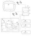
- FIG. 1 is a block diagram schematically showing main parts of an "automatic operation system for a machining center" according to an embodiment of the present invention
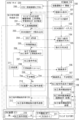
- FIG. FIG. 2 is a flow chart diagram showing an operation example of the main part of the "automatic operation system for the machining center" of FIG. 1
- FIG. 2 is a block diagram mainly schematically showing a portion for carrying out an automatic processing material conveying process in a system different from that in FIG. 1
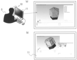
- FIG. 2 is a sample diagram showing an example of a screen when a 3D model of a processed product created in the process of creating a processing command in FIG. 2 is displayed on the display of the PC terminal in FIG.
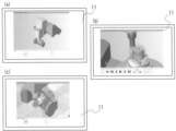
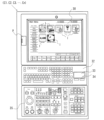
- FIG. 3 is a schematic diagram showing an example of a screen on which an animation video is displayed on the display of a PC terminal during the tool locus simulation of FIG. Screen (c) is the display screen at the end of the simulation. It is a schematic front view which shows the example of a basic composition of the operation panel of each CNC apparatus.
- FIG. 1 is a block diagram schematically showing main parts of an automatic operation system for a machining center according to this embodiment.
- the plurality of machining centers (M1, M2, M3, . These may be mixed.
- automatic operation control is performed for a plurality of machining centers (M1, M2, M3, ..., Mn), and the machine tools (MT1, MT2, MT3, ..., MTn) of each machining center are CNC devices (C1, C2, C3, . . . , Cn) and numerically controlled in conjunction with the automatic tool changer ATC.
- the automatic operation system 1 for a machining center is connected to a cloud server 20 on the Internet network and a cloud-side control unit 21 for the automatic operation system of the machining center provided in the cloud server 20 via a communication line.
- a plurality of machining centers (M1, M2, M3, . , Mn).
- the PC terminal 10 and each CNC device are equipped with 5G-compatible communication devices/modules, and data transmission/reception between each other can be performed in real time with almost no delay by communication connection with the cloud server 20 via the Internet by 5G. done.
- Each CNC device (C1, C2, C3, .
- the configuration may be the same as that of the conventional CNC device.
- a schematic configuration thereof first, as shown in FIG. 6, the front surface of the main body serves as an operation panel, and a touch panel type display 30 is provided on this operation panel.
- the touch panel display 30 displays a menu screen that displays items of various work operation modes for a machine tool provided in advance in the CNC device as icons I, respectively.
- a USB port P is arranged around the display 30 so that various data can be input and output, and a keyboard 32 including a mouse pad 33 and a mouse button 34 is arranged as an input unit 31 below the display 30 . Further, in the area below the keyboard 32, an operation panel 35 having switches and buttons related to various operations of the machine tool is provided.
- each CNC device C1, C2, C3, .
- the automatic tool changer ATC is driven and controlled, and the cutting of the material to be processed is executed while the tools are sequentially exchanged and mounted on the rotary spindle corresponding to each machining process.
- the CNC-device-side control unit 40 includes a CNC-device-side storage unit 41 that stores tool information, various machining programs, and an APC program for automatic operation of the linked automatic workpiece transfer device APC.
- the tool information stored in each CNC device side storage unit includes identification information corresponding to a large number of tools stored in magazines of each machine tool, and the type, shape, and material of each tool linked to this. etc.
- Each tool is managed by identification information, and during automatic operation of machine tools (MT1, MT2, MT3, . are exchanged and mounted at a predetermined timing by the automatic tool changer ATC between the rotary spindle of the machining section and the magazine.
- Each machining center (M1, M2, M3, . Each time, it is updated to the latest tool information (t1', t2', t3', . . . , tn').
- a list 25 is stored.
- the registration list 25 also contains model information (m1, m2, m3, . . . , mn) of the target machining centers (M1, M2, M3, . . . , Mn).
- tool information ( t1, t2, t3, . is provided.
- a machining command automatic creation unit 22 having a process automatic setting function and a machining command creation function for automatically creating a machining command Mc for causing the machine tool to execute the machining process is provided.
- the processing command automatic generation unit 22 also has a characteristic portion extraction function for extracting each characteristic portion of the processed product based on the acquired three-dimensional CAD design data of the processed product. That is, the characteristic part of the processed product applied to the learned model in setting the machining process and creating the machining command is obtained from the three-dimensional CAD design data of the target processed product by this characteristic part extraction function.
- the substantial processing command creation process in the processing command automatic creation unit 22 starts when the 3D CAD design data of the target product to be processed is obtained. Acquisition of this three-dimensional CAD design data is achieved by data transmission from a terminal device, which is the PC terminal 10 in this embodiment.
- the machining command automatic generation unit 22 has a machining center determination unit that determines the machining center to be used for manufacturing a new machined product from among the machining centers (M1, M2, M3, . . . , Mn) registered in the registration list 25. It is provided with a section 23, and determines the machining center to be used this time before acquiring the three-dimensional CAD design data of the target processed product.
- the machining center determination unit 23 causes the liquid crystal display 11 of the PC terminal 10 to display the registration list 25 stored in the cloud storage unit 24 so that any machining center in the list can be selected. .
- the operator O can use the PC terminal 10 to select a machining center suitable for manufacturing the desired processed product from the registration list 25 based on the dimensions and weight of the desired processed product. Therefore, when a selection command signal for the machining center selected by the operator O is transmitted from the PC terminal 10 to the cloud-side control unit 21, the machining center determination unit 23 determines the machining center to be used this time from the registration list 25. At the same time, the corresponding tool information and learned model used for creating the current machining command are designated from the tool information storage unit 26 and the learned model storage unit 27, respectively.
- the machining command automatic creation unit 22 creates the machining command while reading the model information and tool information of the machining center determined to manufacture the current machined product and applying the learned model. It will be.
- the machining process automatic setting function of the machining command automatic generation unit 22 also includes a tool information update function, and the tool information specified when the machining center to be used is determined is updated by this tool information update function. The tool information is updated to the latest tool information stored in the CNC device side storage unit.
- a 3D model of the processed product in the machining process automatic setting function of the machining command automatic generation unit 22, after extracting each characteristic part of the processed product based on the three-dimensional CAD design data of the processed product by the characteristic part extraction function, a 3D model of the processed product , and transmit the image data to display it on the liquid crystal display 11 of the PC terminal 10 .
- one or more different mounting directions of the possible processed product are subsequently selected, a 3D model in each selected mounting direction is also created, and the image data is displayed on the liquid crystal display 11 of the PC terminal 10. It further has a function of displaying it in a selectable manner.
- the operator O can select the optimum mounting direction from among those proposed and displayed on the liquid crystal display 11 .
- the processing command automatic generation unit 22 automatically sets the processing process in the determined mounting direction. can proceed based on
- the machining command automatic creation unit 22 has a simulation function of displaying the automatically created tool trajectory of the machining process as 3D computer graphics, for example, an animation movie on the liquid crystal display 11 of the PC terminal 10;
- An interference detection function is further provided for stopping the moving image and displaying an interference warning when interference occurs between the tool and the non-machining area of the workpiece or the peripheral members of the processed portion during the moving image display.
- interference when interference is detected, it also has a machining command improvement function that changes the tool that caused the interference to another tool and recreates the machining command.
- the material to be processed is automatically transported to a predetermined position in the processing section before the processing command created and transmitted to the CNC device is executed. That is, as shown in the block diagram of FIG. 3, the PC terminal 10 automatically conveys the material to be processed in a different system from the automatic creation of the processing command Mc via the cloud server 20 in FIG. It is assumed that the machine tool of each machining center is provided with an automatic processing material conveying device suitable for the machine model so as to be able to cooperate with it.
- a machining center is a pallet in which a workpiece is exchangeably placed on a pallet by a robot, and the pallet on which the workpiece is placed is controlled to move to a predetermined position in the machining part so that the workpiece is positioned in the machining part.
- the CNC device side control section 40 executes the APC program 42 stored in the CNC device side storage section 41 to operate the pallet changer. APC is automatically controlled.
- the PC terminal 10 directly communicates with the CNC device via the communication line. to the CNC device side control unit 40 to control the driving of the pallet changer APC using the APC program 42, and automatically move the pallet on which the processed material is placed. It shall be moved to complete the transfer of the workpiece to the machine tool processing section.
- the processing command start instructing unit 28 of the cloud-side control unit 21 confirms that the processing material is transported and positioned at a predetermined position of the processing unit of the machine tool, and then executes the previously transmitted processing command.
- a machining command start instruction signal is transmitted to the CNC device side control unit 40 .
- the machining command start instructing unit 28 to confirm the completion state of conveyance of the workpiece, it is possible to use an ATC program end code from the CNC device side.
- the PC terminal 10 since the PC terminal 10 starts the drive control of the automatic processing material conveying device APC, the PC terminal 10 confirms the completion of conveyance, and after confirmation, the processing instruction start signal transmitted from the PC terminal 10 15, a machining instruction start instruction signal is transmitted to the CNC device side control unit 40.
- the transmission of the machining command start signal 15 may be performed immediately by the operator O.
- a machining command start instruction signal may be transmitted at the point in time.
- the PC terminal 10 can acquire a code indicating the end of the ATC program via the CNC device, it is possible to confirm the completion of transportation of the processed material.
- the machine tool is equipped with one or more imaging devices 50, such as a CCD camera, for imaging at least the peripheral area of the machining part, and the image is displayed on the display 30 of the CNC device. Therefore, in the present embodiment, the PC terminal 10 directly acquires the image data 51 of the area around the machining part from the CNC device via the communication line, and displays it on the liquid crystal display 11, so that the machining material in the machining part can be displayed. Conveyance status can be monitored.
- the machining command start signal 15 can be transmitted to the machining command start instruction unit 28 of the side control unit 21 .
- the machining command start instruction unit 28 receives the machining command start signal 15 from the PC terminal 10 and transmits the machining command start command signal to the CNC device side control unit 40 .
- the CNC apparatus side control section 40 Upon receiving the machining instruction start instruction signal from the machining instruction start instructing section 28, the CNC apparatus side control section 40 performs a cycle start to cause the machine tool to execute the previously sent machining instruction.
- the machining command corresponding to the required cutting process is automatically created from the selection of the machining center M1 to be used for manufacturing the target machined product.
- the process up to execution in the machining center M1 will be described below along the flow chart of FIG. 4 and 5 are schematic diagrams showing examples of screens displayed on the liquid crystal display 11 of the PC terminal 10 in each process of the automatic machining process setting process.
- the operator O selects and launches an application corresponding to the "automatic operation of the machining center" mode from various application menus displayed on the liquid crystal display 11 of the PC terminal 10, thereby enabling the automatic operation mode of the machining center.
- Start step 100.
- the operator O enters a pre-registered personal identification number such as his own address and a password, or authentication information such as a face image, etc., to the cloud server 20, and after obtaining authentication, the automatic operation of the machining center is performed.
- the machining command automatic creation unit 22 sends the machining command automatic creation unit 22 to the PC terminal 10 to which access is permitted, and the registration list 25 of the machining centers (M1, M2, M3, . . . , Mn) stored in the cloud-side storage unit 24. data is transmitted, and the registration list 25 is displayed on the liquid crystal display 11 (step 101).
- the operator O selects a machining center suitable for producing the desired processed product from the registration list 25 displayed on the liquid crystal display 11 (step 102). In this embodiment, the machining center M1 is selected.
- a selection command signal indicating that the machining center M1 has been selected is transmitted from the PC terminal 10 to the machining command automatic generation unit 22, and based on the selection command signal, the machining center determination unit 23 determines the machining center M1 to be used this time.
- the model information m1, the tool information t1 and the learned model L1 to be used are specified (step 201).
- the latest tool information t1' stored in the CNC device side storage section 41 of the corresponding CNC device C1 is read out, and the tool information t1 is updated (step 202).
- the operator O selects the machining center M1 to be used, acquires the three-dimensional CAD design data of the target processed product from the data acquisition unit 12, and transmits the data to the processing command automatic generation unit 22.
- three-dimensional CAD design data is stored in a USB, the data is acquired via the USB port as the data acquisition unit 12, but may be read from another computer via a computer network.
- the processing command automatic creation unit 22 After reading the 3D CAD design data (step 203), the processing command automatic creation unit 22 creates a 3D model of the processed product (step 204) based on the 3D CAD design data. Subsequently, one or more possible mounting directions of the processed product are selected, and the image data of the 3D model in each of the selected mounting directions is transmitted to the PC terminal 10, and all characteristic portions are extracted (step 205). )I do.
- the liquid crystal display 11 displays a 3D model of the target processed product in various mounting directions (step 104).
- 3D models with different mounting directions are displayed so that an arbitrary model can be selected from them.
- the central axis of the pentagonal prism is along the vertical direction.
- a mounting direction in which the central axis is along the horizontal direction.
- any side surface of the pentagonal prism portion can be the mounting surface.
- the operator O selects, on the liquid crystal display 11, the 3D model with the optimum mounting direction from among the displayed 3D models with different mounting directions, thereby determining the mounting direction (step 105).
- the bottom surface of the pentagonal prism portion is a surface that does not have a feature and does not require processing, the direction in which this bottom surface becomes the mounting surface, that is, the mounting direction along the vertical direction of the central axis is It can be immediately judged as practical and optimal.
- the PC terminal 10 transmits a decision signal indicating the mounting direction of the selected 3D model to the cloud-side control unit 21 .
- the machining command automatic generation unit 22 starts substantial machining process setting (step 206) based on the mounting direction indicated by the transmitted determination signal.
- a tool suitable for machining each characteristic portion is selected from the tools registered in the latest updated tool information t1, and various Cutting conditions and machining conditions are determined, and the tool locus is also determined based on the machining conditions. Then, a machining process including a tool locus is set from the specification and replacement of tools necessary for cutting each characteristic portion. Then, when there are a plurality of types of characteristic portions, an efficient sequence of processing steps corresponding to all the characteristic portions is determined, and a series of all processing steps necessary for manufacturing the desired processed product are set. Immediately after that, a machining command is created (step 207) for causing the machine tool to execute all the set machining steps.
- step 208 the simulation of the tool trajectory of the set machining process (step 208) is started, and the machining command automatic creation unit 22 is created in this simulation process.
- 3D animation moving image data is transmitted to the PC terminal 10 .
- a 3D animation is displayed on the display 11 (step 106).
- the presence or absence of interference between the tool and the non-machining area of the workpiece or the surrounding members of the machining portion of the machine tool is detected (step 209) along the tool locus. If there is no interference, the simulation animation of the tool locus is displayed to the end without being stopped as shown in FIG. 5(c). In this way, when no interference occurs and interference detection is denied, the machining process and machining command Mc set and created based on the tool locus are complete and can be executed without interference on the machine tool MT1. It can be safely judged that
- a warning signal is sent to the PC terminal 10, the simulation video is stopped on the display 11, and an interference warning is displayed (step 107). .
- the machining command automatic generation unit 22 identifies the tool that caused the interference, reselects the next best tool based on the learned model L1, and changes the tool (step 211). ), the machining conditions and machining trajectory for the changed tool are determined again, and the machining process setting (step 206) is redone. Then, a machining command is created again (step 207) corresponding to the improved machining process. Since this routine from tool change to machining command change is repeated until the occurrence of interference in the simulation is eliminated, an improved machining command with a complete tool and tool locus can be easily created in a short time.
- this machining command Mc is transmitted to the CNC device, and the CNC device side control unit 40 receives the machining command Mc (step 220) is performed.
- a signal is sent to the PC terminal 10 indicating that the processing command Mc has been created.
- the PC terminal 10 confirms completion of the machining command creation (step 108), and directly transmits a signal of a machining material transfer command to the CNC device C1 via the communication line (step 109).
- the CNC device-side control unit 40 receives a processing material transfer command from the PC terminal 10, and uses an APC program 42 stored in advance in the CNC device-side storage unit 41 to transfer a pallet as a processing material automatic transfer device APC.
- the drive of the changer is controlled to transport the material to be processed to a predetermined position in the processing section of the machine tool MT1.
- an imaging device 50 such as a CCD camera mounted on the machine tool MT1 takes an image of the peripheral area of the machining part, and the image data 51 is transmitted to the CNC device side control part 40 .
- the PC terminal 10 directly acquires the image data 51 from the CNC device C1 and displays the monitor image 13 on the display 11. Therefore, the operator O sees the monitor image 13 of the peripheral area of the machining part on the display 11, and receives the execution completion code of the APC program 42 from the CNC device C1, so that the machining material is positioned at the predetermined position of the machining part. You can be sure that it has been transported to When the PC terminal 10 confirms the conveyance of the processing material (step 110), the operator O transmits the processing command start signal 15 to the processing command start instructing unit 28 of the cloud-side control unit 21 (step 111). can be done.
- the machining command start instruction unit 28 determines that the material to be processed has been conveyed by the machining command start signal 15 from the PC terminal 10, and transmits the machining command start instruction signal to the CNC device side control unit 40 (step 212). conduct. That is, until the processing command start signal 15 from the PC terminal 10 is received, the processing command start instructing unit 28 assumes that the processing material has not been completely conveyed and is in a standby state.
- the device-side control unit 40 receives the machining command start instruction signal and performs a cycle start (step 221) on the machine tool MT1 so as to start automatic operation in accordance with the previously received machining command Mc.
- a processing material automatic transfer command signal 14 is sent to the CNC device, and after confirming the completion of transfer on the monitor image 13, the processing command is started at an arbitrary timing. Only by transmitting the signal 15 to the cloud side with the PC terminal 10, from the creation of the machining command for manufacturing the target machined product for the remote machining center to the execution by the machine tool smoothly in real time. It can be carried out.
- the first operator at the first terminal device selects a certain machining center from the registration list 25, it may have already been selected by the second operator on another second terminal device and used in the machining process.
- the registration list 25 is displayed on the display section of the first terminal device in a state in which the machining center cannot be selected. This allows the first operator to select another alternative machining center.
- the first operator can select and use the machining center again after the machining center becomes selectable in the registration list 25 after the second operator finishes using the machining center.
- MT1, MT2, MT3, ..., MTn Machine tool
- ATC Automatic tool changer (pallet changer)
- APC Processing material automatic conveying device 30: (CNC device) touch panel type display 31: input unit 32: keyboard 33: mouse pad 34: mouse button 35: operation panel P: USB port 40: CNC device side control unit 41: CNC device Side storage unit 42: APC program 50: Imaging device 51: Image data
Landscapes
- Engineering & Computer Science (AREA)
- Physics & Mathematics (AREA)
- Automation & Control Theory (AREA)
- General Physics & Mathematics (AREA)
- Manufacturing & Machinery (AREA)
- Human Computer Interaction (AREA)
- Artificial Intelligence (AREA)
- Computing Systems (AREA)
- Computer Vision & Pattern Recognition (AREA)
- Evolutionary Computation (AREA)
- Software Systems (AREA)
- Medical Informatics (AREA)
- Health & Medical Sciences (AREA)
- Mechanical Engineering (AREA)
- Geometry (AREA)
- Business, Economics & Management (AREA)
- Accounting & Taxation (AREA)
- General Business, Economics & Management (AREA)
- Development Economics (AREA)
- Economics (AREA)
- Numerical Control (AREA)
- General Factory Administration (AREA)
Abstract
Description
各マシニングセンタの前記CNC装置に通信回線を介して接続されたネットワーク上のクラウドサーバに設けられ、各工作機械用の加工指令を作成して対応するCNC装置に前記加工指令を送信するクラウド側制御部と、目的とする加工製品の3次元CAD設計データが入力され、該3次元CAD設計データを前記クラウド側制御部に通信回線を介して送信すると共に、前記クラウド側制御部から送信される情報を表示部に表示する1つ以上の端末装置と、を備え、
各CNC装置は、
予め定められた加工指令に沿って、前記工作機械の加工部と前記自動工具交換装置とに対する駆動制御を行い、前記加工指令に含まれる各加工工程に対応して工具を前記加工部の回転主軸に交換装着させながら加工素材への切削加工を実行させるCNC装置側制御部と、
前記回転主軸に対して前記自動工具交換装置を介して交換装着可能に収納されている複数の工具の識別情報と各工具の収納位置情報、および前記識別情報に対応する各工具の材質、形状と、を含む工具情報が保存されているCNC装置側記憶部と、を備え、
前記クラウド側制御部は、
前記端末装置から送信された前記3次元CAD設計データに基づいて、予め選択されたマシニングセンタの工作機械に加工素材を目的の加工製品まで切削加工させるのに必要な全加工工程を該工作機械に実行させる加工指令を自動的に作成する加工指令自動作成部と、
駆動制御対象である全マシニングセンタがその機種情報と共に登録された登録リストが格納されているクラウド側記憶部と、を備え、
前記クラウド側記憶部は、工作機械毎の工具情報と、予め各種切削加工の特徴別に当該切削加工が実行された際の使用工具と切削条件とを含む加工条件および工具軌跡とその実行プログラムを含む加工データを対応させて学習させられて生成された学習済みモデルとが格納されており、
前記加工指令自動作成部は、
前記加工素材の形状を基準として前記加工製品の3次元CAD設計データから切削加工の特徴部を抽出する特徴部抽出機能と、
前記選択されたマシニングセンタに対応する学習済みモデルに対して、対応する工具情報と共に、前記特徴部抽出機能によって抽出された各特徴部を適用することによって各特徴部についての切削加工に必要な加工条件を自動的に決定し、該加工条件に基づいて工具軌跡を含む加工工程を自動的に設定する加工工程自動設定機能と、
前記特徴部抽出機能によって抽出された特徴部の全部の加工工程を実行する手順を決定して前記加工製品を完成するのに必要な一連の全加工工程を設定する全加工工程設定機能と、
設定された前記全加工工程を前記工作機械に実行させる加工指令を前記学習済みモデルに基づいて作成する加工指令作成機能、とを備え、作成された前記加工指令を対応する前記CNC装置側制御部へ送信するものであり、
前記加工指令自動作成部の前記加工工程自動設定機能は、
前記学習済みモデルに対して前記各特徴部と共に適用する前記工具情報を、その適用の前に、前記選択されたマシニングセンタのCNC装置側記憶部に保存されている最新の工具情報を参照して更新する工具情報更新機能と、
前記3次元CAD設計データに基づいて、加工製品の3Dモデルを作成して前記端末装置の表示部に前記3Dモデルをディスプレイ表示させると共に、前記加工製品の前記工作機械の加工部への可能な1つ以上の異なる取付方向を選出し、選出された各取付方向の状態で前記3Dモデルを選択可能に前記端末装置の表示部にディスプレイ表示させる機能と、を備えており、前記端末装置にて選択された取付方向に基づいて、更新された最新の前記工具情報を用いて各特徴部の切削加工のための加工工程を自動的に設定するものであり、
前記端末装置は、前記加工指令自動作成部にて作成された前記加工指令が前記CNC装置側制御部に送信された後、操作者による任意のタイミングであるいは予め設定された時刻に達した時点で、前記クラウド側制御部へ加工指令開始信号を送信する機能を有し、
前記クラウド側制御部は、前記端末装置からの前記加工指令開始信号を受信した時点で、前記CNC装置側制御部に加工指令開始指示信号を送信して前記加工指令に沿った切削加工の実行を前記工作機械に開始させる加工指令開始指示部、をさらに備えているものである。
O:操作者
10:PC端末
11:ディスプレイ
12:データ取得部
13:モニタ画像
14:加工素材自動搬送指令信号
15:加工指令開始信号
20:クラウドサーバ
21:クラウド側制御部
22:加工指令自動作成部
23:マシニングセンタ決定部
24:クラウド側記憶部
25:登録リスト
26:工具情報格納部
27:学習済みモデル格納部
28:加工指令開始指示部
M1,M2,M3,…,Mn:マシニングセンタ
m1,m2,m3,…,mn:機種情報
t1,t2,t3,…,tn:工具情報
t1’,t2’,t3’,…,tn’(CNC装置側)工具情報
L1,L2,L3,…,Ln:学習済みモデル
C1,C2,C3,…,Cn:CNC装置
MT1,MT2,MT3,…,MTn:工作機械
ATC:自動工具交換装置(パレットチェンジャ)
APC:加工素材自動搬送装置
30:(CNC装置)タッチパネル式ディスプレイ
31:入力部
32:キーボード
33:マウスパッド
34:マウスボタン
35:操作パネル
P:USBポート
40:CNC装置側制御部
41:CNC装置側記憶部
42:APC用プログラム
50:撮像装置
51:画像データ
Claims (6)
- 各々の工作機械と自動工具交換装置との数値制御を行うCNC装置を備えた複数のマシニングセンタに対して選択的に自動運転制御を行うマシニングセンタの自動運転システムであって、
各マシニングセンタの前記CNC装置に通信回線を介して接続されたネットワーク上のクラウドサーバに設けられ、各工作機械用の加工指令を作成して対応するCNC装置に前記加工指令を送信するクラウド側制御部と、目的とする加工製品の3次元CAD設計データが入力され、該3次元CAD設計データを前記クラウド側制御部に通信回線を介して送信すると共に、前記クラウド側制御部から送信される情報を表示部に表示する1つ以上の端末装置と、を備え、
各CNC装置は、
予め定められた加工指令に沿って、前記工作機械の加工部と前記自動工具交換装置とに対する駆動制御を行い、前記加工指令に含まれる各加工工程に対応して工具を前記加工部の回転主軸に交換装着させながら加工素材への切削加工を実行させるCNC装置側制御部と、
前記回転主軸に対して前記自動工具交換装置を介して交換装着可能に収納されている複数の工具の識別情報と各工具の収納位置情報、および前記識別情報に対応する各工具の材質、形状と、を含む工具情報が保存されているCNC装置側記憶部と、を備え、
前記クラウド側制御部は、
前記端末装置から送信された前記3次元CAD設計データに基づいて、予め選択されたマシニングセンタの工作機械に加工素材を目的の加工製品まで切削加工させるのに必要な全加工工程を該工作機械に実行させる加工指令を自動的に作成する加工指令自動作成部と、
駆動制御対象である全マシニングセンタがその機種情報と共に登録された登録リストが格納されているクラウド側記憶部と、を備え、
前記クラウド側記憶部は、工作機械毎の工具情報と、予め各種切削加工の特徴別に当該切削加工が実行された際の使用工具と切削条件とを含む加工条件および工具軌跡とその実行プログラムを含む加工データを対応させて学習させられて生成された学習済みモデルが格納されており、
前記加工指令自動作成部は、
前記加工素材の形状を基準として前記加工製品の3次元CAD設計データから切削加工の特徴部を抽出する特徴部抽出機能と、
前記選択されたマシニングセンタに対応する学習済みモデルに対して、対応する工具情報と共に、前記特徴部抽出機能によって抽出された各特徴部を適用することによって各特徴部についての切削加工に必要な加工条件を自動的に決定し、該加工条件に基づいて工具軌跡を含む加工工程を自動的に設定する加工工程自動設定機能と、
前記特徴部抽出機能によって抽出された特徴部の全部の加工工程を実行する手順を決定して前記加工製品を完成するのに必要な一連の全加工工程を設定する全加工工程設定機能と、
設定された前記全加工工程を前記工作機械に実行させる加工指令を前記学習済みモデルに基づいて作成する加工指令作成機能、とを備え、作成された前記加工指令を対応する前記CNC装置側制御部へ送信するものであり、
前記加工指令自動作成部の前記加工工程自動設定機能は、
前記学習済みモデルに対して前記各特徴部と共に適用する前記工具情報を、その適用の前に、前記選択されたマシニングセンタのCNC装置側記憶部に保存されている最新の工具情報を参照して更新する工具情報更新機能と、
前記3次元CAD設計データに基づいて、加工製品の3Dモデルを作成して前記端末装置の表示部に前記3Dモデルをディスプレイ表示させると共に、前記加工製品の前記工作機械の加工部への可能な1つ以上の異なる取付方向を選出し、選出された各取付方向の状態で前記3Dモデルを選択可能に前記端末装置の表示部にディスプレイ表示させる機能と、を備えており、前記端末装置にて選択された取付方向に基づいて、更新された最新の前記工具情報を用いて各特徴部の切削加工のための加工工程を自動的に設定するものであり、
前記端末装置は、前記加工指令自動作成部にて作成された前記加工指令が前記CNC装置側制御部に送信された後、操作者による任意のタイミングであるいは予め設定された時刻に達した時点で、前記クラウド側制御部へ加工指令開始信号を送信する機能を有し、
前記クラウド側制御部は、前記端末装置からの前記加工指令開始信号を受信した時点で、前記CNC装置側制御部に加工指令開始指示信号を送信して前記加工指令に沿った切削加工の実行を前記工作機械に開始させる加工指令開始指示部、をさらに備えていることを特徴とする、マシニングセンタの自動運転システム。 - 前記加工指令自動作成部は、
設定された加工工程の工具軌跡を前記端末装置の表示部に3Dコンピュータグラフィックスの動画として表示させるシミュレーション機能と、
前記動画の表示中に工具と加工素材の非加工領域または加工部の周辺部材との干渉が発生した時点で前記動画を停止させて干渉警告を表示させる干渉検知機能と、
干渉検知時にその干渉を発生した工具を別の工具に変更し、変更した工具に対応する加工条件に基づいた別の工具軌跡を決定して別の加工工程を設定し直して改良された加工指令を作成する加工指令改良機能と、をさらに備えていることを特徴とする請求項1に記載のマシニングセンタの自動運転システム。 - 前記端末装置は、各マシニングセンタのCNC装置と通信回線を介して各種信号の送受信可能に接続されており、
各CNC装置側記憶部は、その工作機械の加工部へ加工素材を自動搬送するための加工素材自動搬送装置を駆動制御する加工素材搬送プログラムが格納されており、
前記端末装置は、
前記クラウド側制御部から前記CNC装置側制御部へ前記加工指令が送信された後に、前記通信回線を介して、前記CNC装置側制御部に対して、前記加工素材搬送プログラムに沿って前記加工素材自動搬送装置を駆動制御させる加工素材搬送指令信号を送信する機能と、
前記加工素材の前記工作機械の加工部への搬送が完了していることが確認された後に前記加工指令開始指示部へ前記加工指令開始信号を送信する機能と、をさらに備えていることを特徴とする請求項1又は2に記載のマシニングセンタの自動運転システム。 - 前記端末装置は、
前記工作機械の加工部への前記加工素材の搬送が完了しているかどうかを操作者による目視で確認するモニタ機能と、加工素材の搬送完了状態を前記目視で確認した後に前記加工指令開始指示部へ前記加工指令開始信号を送信する機能と、を備えており、
前記モニタ機能は、各工作機械に設置されている一つ以上の撮像装置によって得られる加工素材設置位置を含む加工部周辺領域の画像データを前記CNC装置から前記通信回線を介して取得し、前記端末装置の表示部に前記加工部周辺領域のモニタ画像を表示させる機能を含むものであることを特徴とする請求項3に記載のマシニングセンタの自動運転システム。 - 前記加工指令自動作成部は、前記登録リストに登録されているマシニングセンタの中から前記加工製品の切削加工に使用するマシニングセンタを決定するマシニングセンタ決定部を備えており、
前記マシニングセンタ決定部は、
前記端末装置の表示部に、前記登録リストを該リスト内の任意のマシニングセンタを選択可能に表示させると共に、選択されたマシニングセンタを示す選択指令信号を前記端末装置から受けて使用するマシニグセンタを決定する機能および/または、
前記加工指令自動作成部で作成された前記3Dモデルから取得される前記加工製品の寸法および重量を含む設計情報と、前記登録リストに含まれる各マシニングセンタの機種情報とに基づいて、前記加工製品の切削加工に適した機種のマシニングセンタを選択して使用するマシニングセンタを決定する機能を備えていること特徴とする請求項1~4のいずれか1項に記載のマシニングセンタの自動運転システム。 - 前記端末装置が複数であって、前記マシニングセンタ決定部が、前記端末装置の表示部に前記登録リストを該リスト内の任意のマシニングセンタを選択可能に表示させると共に、選択されたマシニングセンタを示す選択指令信号を受けて使用するマシニングセンタを決定する機能を備えている場合において、
前記マシニングセンタ決定部は、一つの端末装置によって使用されるマシニングセンタが既に決定されると、他の端末装置の表示部に前記登録リストを表示させる際に、前記既に決定されたマシニングセンタを選択不可能状態とする機能をさらに備えていることを特徴とする請求項5に記載のマシニングセンタの自動運転システム。
Priority Applications (3)
| Application Number | Priority Date | Filing Date | Title |
|---|---|---|---|
| US18/275,292 US12493283B2 (en) | 2021-08-11 | 2022-07-28 | Machining center automatic operating system |
| EP22855805.2A EP4260976A4 (en) | 2021-08-11 | 2022-07-28 | AUTOMATIC MACHINING CENTER OPERATING SYSTEM |
| CA3209287A CA3209287A1 (en) | 2021-08-11 | 2022-07-28 | Machining center automatic operating system |
Applications Claiming Priority (2)
| Application Number | Priority Date | Filing Date | Title |
|---|---|---|---|
| JP2021131069A JP7154514B1 (ja) | 2021-08-11 | 2021-08-11 | マシニングセンタの自動運転システム |
| JP2021-131069 | 2021-08-11 |
Publications (1)
| Publication Number | Publication Date |
|---|---|
| WO2023017742A1 true WO2023017742A1 (ja) | 2023-02-16 |
Family
ID=83658124
Family Applications (1)
| Application Number | Title | Priority Date | Filing Date |
|---|---|---|---|
| PCT/JP2022/029152 Ceased WO2023017742A1 (ja) | 2021-08-11 | 2022-07-28 | マシニングセンタの自動運転システム |
Country Status (6)
| Country | Link |
|---|---|
| US (1) | US12493283B2 (ja) |
| EP (1) | EP4260976A4 (ja) |
| JP (1) | JP7154514B1 (ja) |
| CA (1) | CA3209287A1 (ja) |
| TW (2) | TW202311881A (ja) |
| WO (1) | WO2023017742A1 (ja) |
Cited By (1)
| Publication number | Priority date | Publication date | Assignee | Title |
|---|---|---|---|---|
| WO2025057383A1 (ja) * | 2023-09-14 | 2025-03-20 | ファナック株式会社 | 実行装置、判断システム、及びコンピュータが読み取り可能な記憶媒体 |
Families Citing this family (1)
| Publication number | Priority date | Publication date | Assignee | Title |
|---|---|---|---|---|
| WO2024095400A1 (ja) * | 2022-11-02 | 2024-05-10 | 株式会社Fuji | 加工提案表作成装置、及び加工提案表作成プログラム |
Citations (7)
| Publication number | Priority date | Publication date | Assignee | Title |
|---|---|---|---|---|
| JPH0419790B2 (ja) | 1986-06-20 | 1992-03-31 | Takano Corp | |
| JP2016071407A (ja) | 2014-09-26 | 2016-05-09 | ファナック株式会社 | ホストコンピュータ上の制御用ソフトウェアを使用した数値制御装置 |
| CN106292535A (zh) * | 2016-08-31 | 2017-01-04 | 皿智智慧制造(大连)有限公司 | 数控机床加工系统及基于云平台的数控机床加工系统 |
| JP2020024676A (ja) * | 2018-06-14 | 2020-02-13 | サンドビック マシニング ソリューションズ アクティエボラーグ | データベースから選択された方針に基づく機械加工 |
| JP6719790B1 (ja) * | 2019-09-05 | 2020-07-08 | キタムラ機械株式会社 | Cadデータによるマシニングセンタの自動運転装置 |
| JP2020129220A (ja) * | 2019-02-07 | 2020-08-27 | ファナック株式会社 | 管理装置及び管理システム |
| JP2021012542A (ja) | 2019-07-05 | 2021-02-04 | 株式会社日立製作所 | 機械加工管理方法及び機械加工管理システム |
Family Cites Families (7)
| Publication number | Priority date | Publication date | Assignee | Title |
|---|---|---|---|---|
| JP3338373B2 (ja) * | 1998-06-05 | 2002-10-28 | 株式会社アマダ | 板金加工統合支援システム |
| TW201024021A (en) | 2008-12-26 | 2010-07-01 | Pinnacle Machine Tool Co Ltd | Programmable control method for rotary nozzle of machine tool and device thereof |
| CN102749885B (zh) * | 2012-07-18 | 2014-08-06 | 石毅 | 云数控系统 |
| CN105094089B (zh) * | 2015-06-26 | 2018-04-03 | 上海交通大学 | 一种基于编码器播放器体系架构的工业控制系统 |
| TWI645933B (zh) * | 2017-12-08 | 2019-01-01 | 財團法人工業技術研究院 | 確認刀具位置之方法與工具機系統 |
| US10585994B2 (en) * | 2018-03-07 | 2020-03-10 | Paperless Parts, Inc. | Systems and methods for secure, oblivious-client optimization of manufacturing processes |
| SE1900215A1 (en) * | 2019-12-20 | 2021-03-30 | Sandvik Machining Solutions Ab | Method and system for optimizing a manufacturing process |
-
2021
- 2021-08-11 JP JP2021131069A patent/JP7154514B1/ja active Active
-
2022
- 2022-07-14 TW TW111126411A patent/TW202311881A/zh unknown
- 2022-07-14 TW TW114139611A patent/TW202605525A/zh unknown
- 2022-07-28 EP EP22855805.2A patent/EP4260976A4/en active Pending
- 2022-07-28 US US18/275,292 patent/US12493283B2/en active Active
- 2022-07-28 CA CA3209287A patent/CA3209287A1/en active Pending
- 2022-07-28 WO PCT/JP2022/029152 patent/WO2023017742A1/ja not_active Ceased
Patent Citations (7)
| Publication number | Priority date | Publication date | Assignee | Title |
|---|---|---|---|---|
| JPH0419790B2 (ja) | 1986-06-20 | 1992-03-31 | Takano Corp | |
| JP2016071407A (ja) | 2014-09-26 | 2016-05-09 | ファナック株式会社 | ホストコンピュータ上の制御用ソフトウェアを使用した数値制御装置 |
| CN106292535A (zh) * | 2016-08-31 | 2017-01-04 | 皿智智慧制造(大连)有限公司 | 数控机床加工系统及基于云平台的数控机床加工系统 |
| JP2020024676A (ja) * | 2018-06-14 | 2020-02-13 | サンドビック マシニング ソリューションズ アクティエボラーグ | データベースから選択された方針に基づく機械加工 |
| JP2020129220A (ja) * | 2019-02-07 | 2020-08-27 | ファナック株式会社 | 管理装置及び管理システム |
| JP2021012542A (ja) | 2019-07-05 | 2021-02-04 | 株式会社日立製作所 | 機械加工管理方法及び機械加工管理システム |
| JP6719790B1 (ja) * | 2019-09-05 | 2020-07-08 | キタムラ機械株式会社 | Cadデータによるマシニングセンタの自動運転装置 |
Non-Patent Citations (1)
| Title |
|---|
| See also references of EP4260976A4 |
Cited By (1)
| Publication number | Priority date | Publication date | Assignee | Title |
|---|---|---|---|---|
| WO2025057383A1 (ja) * | 2023-09-14 | 2025-03-20 | ファナック株式会社 | 実行装置、判断システム、及びコンピュータが読み取り可能な記憶媒体 |
Also Published As
| Publication number | Publication date |
|---|---|
| JP7154514B1 (ja) | 2022-10-18 |
| CA3209287A1 (en) | 2023-02-16 |
| EP4260976A1 (en) | 2023-10-18 |
| US12493283B2 (en) | 2025-12-09 |
| TW202311881A (zh) | 2023-03-16 |
| US20240231320A9 (en) | 2024-07-11 |
| EP4260976A4 (en) | 2024-11-20 |
| JP2023025754A (ja) | 2023-02-24 |
| US20240134351A1 (en) | 2024-04-25 |
| TW202605525A (zh) | 2026-02-01 |
Similar Documents
| Publication | Publication Date | Title |
|---|---|---|
| JP7296672B2 (ja) | マシニングセンタの自動運転システム | |
| EP2081096B1 (en) | Controller of work piece-conveying robot | |
| CN101898318B (zh) | 包含机器人和机床的加工系统中的机器人控制系统 | |
| EP3816745B1 (en) | Device for automatically operating machining center using cad data | |
| JP7060540B2 (ja) | 加工制御システム及び加工システム | |
| US20170300037A1 (en) | Subtractive machining work center | |
| US20190030715A1 (en) | Robot controller and production system | |
| JP2018124910A (ja) | 加工機に対して移動ロボットが物品の搬入及び搬出を行う加工システム、及び機械制御装置 | |
| JP7154514B1 (ja) | マシニングセンタの自動運転システム | |
| CN111538296A (zh) | 管理装置和管理系统 | |
| JP2017144542A (ja) | ロボット装置 | |
| WO2004074953A1 (ja) | 数値制御装置 | |
| US10974385B2 (en) | Redundant, diverse collision monitoring | |
| KR101108211B1 (ko) | 복합선반용 파트프로그래밍 장치 및 복합 공정간 동기화 프로그램 생성방법 | |
| KR101760121B1 (ko) | 가공계획 수립과 가공시간 예측이 가능한 nc 공작기계 운용 시스템 및 방법 | |
| KR101539266B1 (ko) | 지능형 복합 절삭가공시스템 | |
| KR100481032B1 (ko) | 공작물 기계 원점 좌표 설정 시스템 및 방법 | |
| JP4606658B2 (ja) | 工作機械、その数値制御装置およびその制御方法 | |
| US5583409A (en) | Numerical control apparatus and method for controlling a machine | |
| JP3248081B2 (ja) | 切削軸の自動変更機能付き自動プログラム作成装置 | |
| JP2002268716A (ja) | Nc加工装置の遠隔モニタリング・制御装置とその方法及びこれに用いる手動パルスハンドル | |
| EP3206099A1 (en) | An mmi and a method for controlling an nc machine tool process | |
| KR0155014B1 (ko) | 수치 제어 장치 | |
| JPS61203251A (ja) | 工具干渉チエツク方式 | |
| EP4068020A1 (en) | Display control system |
Legal Events
| Date | Code | Title | Description |
|---|---|---|---|
| 121 | Ep: the epo has been informed by wipo that ep was designated in this application |
Ref document number: 22855805 Country of ref document: EP Kind code of ref document: A1 |
|
| ENP | Entry into the national phase |
Ref document number: 2022855805 Country of ref document: EP Effective date: 20230710 |
|
| WWE | Wipo information: entry into national phase |
Ref document number: 18275292 Country of ref document: US |
|
| WWE | Wipo information: entry into national phase |
Ref document number: 3209287 Country of ref document: CA |
|
| NENP | Non-entry into the national phase |
Ref country code: DE |