WO2023021596A1 - 騒音制御方法及び騒音制御装置 - Google Patents
騒音制御方法及び騒音制御装置 Download PDFInfo
- Publication number
- WO2023021596A1 WO2023021596A1 PCT/JP2021/030133 JP2021030133W WO2023021596A1 WO 2023021596 A1 WO2023021596 A1 WO 2023021596A1 JP 2021030133 W JP2021030133 W JP 2021030133W WO 2023021596 A1 WO2023021596 A1 WO 2023021596A1
- Authority
- WO
- WIPO (PCT)
- Prior art keywords
- noise
- engine
- controller
- performance
- reducing
- Prior art date
- Legal status (The legal status is an assumption and is not a legal conclusion. Google has not performed a legal analysis and makes no representation as to the accuracy of the status listed.)
- Ceased
Links
Images



Classifications
-
- G—PHYSICS
- G10—MUSICAL INSTRUMENTS; ACOUSTICS
- G10K—SOUND-PRODUCING DEVICES; METHODS OR DEVICES FOR PROTECTING AGAINST, OR FOR DAMPING, NOISE OR OTHER ACOUSTIC WAVES IN GENERAL; ACOUSTICS NOT OTHERWISE PROVIDED FOR
- G10K11/00—Methods or devices for transmitting, conducting or directing sound in general; Methods or devices for protecting against, or for damping, noise or other acoustic waves in general
- G10K11/16—Methods or devices for protecting against, or for damping, noise or other acoustic waves in general
- G10K11/175—Methods or devices for protecting against, or for damping, noise or other acoustic waves in general using interference effects; Masking sound
- G10K11/178—Methods or devices for protecting against, or for damping, noise or other acoustic waves in general using interference effects; Masking sound by electro-acoustically regenerating the original acoustic waves in anti-phase
- G10K11/1783—Methods or devices for protecting against, or for damping, noise or other acoustic waves in general using interference effects; Masking sound by electro-acoustically regenerating the original acoustic waves in anti-phase handling or detecting of non-standard events or conditions, e.g. changing operating modes under specific operating conditions
-
- B—PERFORMING OPERATIONS; TRANSPORTING
- B60—VEHICLES IN GENERAL
- B60R—VEHICLES, VEHICLE FITTINGS, OR VEHICLE PARTS, NOT OTHERWISE PROVIDED FOR
- B60R11/00—Arrangements for holding or mounting articles, not otherwise provided for
- B60R11/02—Arrangements for holding or mounting articles, not otherwise provided for for radio sets, television sets, telephones, or the like; Arrangement of controls thereof
-
- G—PHYSICS
- G10—MUSICAL INSTRUMENTS; ACOUSTICS
- G10K—SOUND-PRODUCING DEVICES; METHODS OR DEVICES FOR PROTECTING AGAINST, OR FOR DAMPING, NOISE OR OTHER ACOUSTIC WAVES IN GENERAL; ACOUSTICS NOT OTHERWISE PROVIDED FOR
- G10K11/00—Methods or devices for transmitting, conducting or directing sound in general; Methods or devices for protecting against, or for damping, noise or other acoustic waves in general
- G10K11/16—Methods or devices for protecting against, or for damping, noise or other acoustic waves in general
- G10K11/175—Methods or devices for protecting against, or for damping, noise or other acoustic waves in general using interference effects; Masking sound
-
- G—PHYSICS
- G10—MUSICAL INSTRUMENTS; ACOUSTICS
- G10K—SOUND-PRODUCING DEVICES; METHODS OR DEVICES FOR PROTECTING AGAINST, OR FOR DAMPING, NOISE OR OTHER ACOUSTIC WAVES IN GENERAL; ACOUSTICS NOT OTHERWISE PROVIDED FOR
- G10K11/00—Methods or devices for transmitting, conducting or directing sound in general; Methods or devices for protecting against, or for damping, noise or other acoustic waves in general
- G10K11/16—Methods or devices for protecting against, or for damping, noise or other acoustic waves in general
- G10K11/175—Methods or devices for protecting against, or for damping, noise or other acoustic waves in general using interference effects; Masking sound
- G10K11/178—Methods or devices for protecting against, or for damping, noise or other acoustic waves in general using interference effects; Masking sound by electro-acoustically regenerating the original acoustic waves in anti-phase
-
- G—PHYSICS
- G10—MUSICAL INSTRUMENTS; ACOUSTICS
- G10K—SOUND-PRODUCING DEVICES; METHODS OR DEVICES FOR PROTECTING AGAINST, OR FOR DAMPING, NOISE OR OTHER ACOUSTIC WAVES IN GENERAL; ACOUSTICS NOT OTHERWISE PROVIDED FOR
- G10K11/00—Methods or devices for transmitting, conducting or directing sound in general; Methods or devices for protecting against, or for damping, noise or other acoustic waves in general
- G10K11/16—Methods or devices for protecting against, or for damping, noise or other acoustic waves in general
- G10K11/175—Methods or devices for protecting against, or for damping, noise or other acoustic waves in general using interference effects; Masking sound
- G10K11/178—Methods or devices for protecting against, or for damping, noise or other acoustic waves in general using interference effects; Masking sound by electro-acoustically regenerating the original acoustic waves in anti-phase
- G10K11/1781—Methods or devices for protecting against, or for damping, noise or other acoustic waves in general using interference effects; Masking sound by electro-acoustically regenerating the original acoustic waves in anti-phase characterised by the analysis of input or output signals, e.g. frequency range, modes, transfer functions
- G10K11/17821—Methods or devices for protecting against, or for damping, noise or other acoustic waves in general using interference effects; Masking sound by electro-acoustically regenerating the original acoustic waves in anti-phase characterised by the analysis of input or output signals, e.g. frequency range, modes, transfer functions characterised by the analysis of the input signals only
-
- G—PHYSICS
- G10—MUSICAL INSTRUMENTS; ACOUSTICS
- G10K—SOUND-PRODUCING DEVICES; METHODS OR DEVICES FOR PROTECTING AGAINST, OR FOR DAMPING, NOISE OR OTHER ACOUSTIC WAVES IN GENERAL; ACOUSTICS NOT OTHERWISE PROVIDED FOR
- G10K11/00—Methods or devices for transmitting, conducting or directing sound in general; Methods or devices for protecting against, or for damping, noise or other acoustic waves in general
- G10K11/16—Methods or devices for protecting against, or for damping, noise or other acoustic waves in general
- G10K11/175—Methods or devices for protecting against, or for damping, noise or other acoustic waves in general using interference effects; Masking sound
- G10K11/178—Methods or devices for protecting against, or for damping, noise or other acoustic waves in general using interference effects; Masking sound by electro-acoustically regenerating the original acoustic waves in anti-phase
- G10K11/1781—Methods or devices for protecting against, or for damping, noise or other acoustic waves in general using interference effects; Masking sound by electro-acoustically regenerating the original acoustic waves in anti-phase characterised by the analysis of input or output signals, e.g. frequency range, modes, transfer functions
- G10K11/17821—Methods or devices for protecting against, or for damping, noise or other acoustic waves in general using interference effects; Masking sound by electro-acoustically regenerating the original acoustic waves in anti-phase characterised by the analysis of input or output signals, e.g. frequency range, modes, transfer functions characterised by the analysis of the input signals only
- G10K11/17823—Reference signals, e.g. ambient acoustic environment
-
- G—PHYSICS
- G10—MUSICAL INSTRUMENTS; ACOUSTICS
- G10K—SOUND-PRODUCING DEVICES; METHODS OR DEVICES FOR PROTECTING AGAINST, OR FOR DAMPING, NOISE OR OTHER ACOUSTIC WAVES IN GENERAL; ACOUSTICS NOT OTHERWISE PROVIDED FOR
- G10K11/00—Methods or devices for transmitting, conducting or directing sound in general; Methods or devices for protecting against, or for damping, noise or other acoustic waves in general
- G10K11/16—Methods or devices for protecting against, or for damping, noise or other acoustic waves in general
- G10K11/175—Methods or devices for protecting against, or for damping, noise or other acoustic waves in general using interference effects; Masking sound
- G10K11/178—Methods or devices for protecting against, or for damping, noise or other acoustic waves in general using interference effects; Masking sound by electro-acoustically regenerating the original acoustic waves in anti-phase
- G10K11/1787—General system configurations
- G10K11/17873—General system configurations using a reference signal without an error signal, e.g. pure feedforward
-
- G—PHYSICS
- G10—MUSICAL INSTRUMENTS; ACOUSTICS
- G10K—SOUND-PRODUCING DEVICES; METHODS OR DEVICES FOR PROTECTING AGAINST, OR FOR DAMPING, NOISE OR OTHER ACOUSTIC WAVES IN GENERAL; ACOUSTICS NOT OTHERWISE PROVIDED FOR
- G10K11/00—Methods or devices for transmitting, conducting or directing sound in general; Methods or devices for protecting against, or for damping, noise or other acoustic waves in general
- G10K11/16—Methods or devices for protecting against, or for damping, noise or other acoustic waves in general
- G10K11/175—Methods or devices for protecting against, or for damping, noise or other acoustic waves in general using interference effects; Masking sound
- G10K11/178—Methods or devices for protecting against, or for damping, noise or other acoustic waves in general using interference effects; Masking sound by electro-acoustically regenerating the original acoustic waves in anti-phase
- G10K11/1787—General system configurations
- G10K11/17879—General system configurations using both a reference signal and an error signal
- G10K11/17883—General system configurations using both a reference signal and an error signal the reference signal being derived from a machine operating condition, e.g. engine RPM or vehicle speed
-
- G—PHYSICS
- G10—MUSICAL INSTRUMENTS; ACOUSTICS
- G10K—SOUND-PRODUCING DEVICES; METHODS OR DEVICES FOR PROTECTING AGAINST, OR FOR DAMPING, NOISE OR OTHER ACOUSTIC WAVES IN GENERAL; ACOUSTICS NOT OTHERWISE PROVIDED FOR
- G10K2210/00—Details of active noise control [ANC] covered by G10K11/178 but not provided for in any of its subgroups
- G10K2210/10—Applications
- G10K2210/128—Vehicles
- G10K2210/1282—Automobiles
Definitions
- the present invention relates to a noise control method and a noise control device.
- Patent Document 1 an invention for reducing noise (mainly road noise) inside a vehicle has been known (Patent Document 1).
- the invention described in Patent Document 1 stops the adaptive operation of the controller when it is determined that the change state of the transfer function from the noise source to the evaluation point exceeds a predetermined state.
- the present invention has been made in view of the above problems, and its object is to provide a noise control method and a noise control device that make it difficult for passengers to notice engine noise.
- a noise control method reduces performance for reducing noise caused by vibrations input from the road surface according to the state of the engine.
- FIG. 1 is a configuration example of a noise control device 1 according to an embodiment of the present invention.
- FIG. 2 is a flowchart for explaining an operation example of the noise control device 1.
- FIG. FIG. 3 is a graph showing the relationship between engine speed and noise level.
- FIG. 4 is a flowchart for explaining an operation example of the noise control device 1.
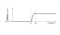
- FIG. FIG. 5 is a diagram for explaining an example of timing for reducing road noise reduction performance.
- FIG. 6 is a diagram for explaining an example of timing for reducing road noise reduction performance.
- FIG. 7 is a graph showing the relationship between frequency and noise level.
- FIG. 8 is a flow chart for explaining an operation example of the noise control device 1.
- FIG. FIG. 9 is a flowchart for explaining an operation example of the noise control device 1.
- FIG. 10 is a diagram illustrating an example of the timing of outputting sound.
- FIG. 11 is a flowchart for explaining an operation example of the noise control device 1.
- FIG. 12A and 12B are diagrams for explaining another operation example of the noise control device 1.
- FIG. 13A and 13B are diagrams for explaining another operation example of the noise control device 1.
- FIG. 14 is a graph showing the relationship between frequency and noise level.
- the noise control device 1 is installed inside the vehicle. As shown in FIG. 1, the noise control device 1 includes a wheel speed sensor 10, an engine 11, an acceleration sensor 12, a microphone 13, a controller 20, and a speaker 30.
- the wheel speed sensor 10 detects the rotational speed of each tire and outputs a signal indicating the detected rotational speed to the controller 20 .
- the engine mounted on the vehicle is used to drive the tires.
- the engine 11 according to this embodiment will be described as being used only for power generation. That is, the engine 11 according to this embodiment is not connected to tires, but is connected to a generator (not shown).
- the engine 11 turns a generator, which produces electricity. However, it is not limited to this.
- the engine 11 may be connected to the tires.
- connection used herein may mean “indirect connection” or “direct connection”.
- the engine 11 outputs a signal indicating its own state to the controller 20 .
- the state of the engine 11 includes, for example, the number of revolutions of the engine 11, a state in which the engine 11 will start in the future, and a state in which the engine 11 will stop in the future.
- the signals that the engine 11 outputs to the controller 20 include a signal indicating the rotation speed of the engine 11, a signal indicating that the engine 11 will start in the future, and a signal indicating that the engine 11 will stop in the future.
- a plurality of acceleration sensors 12 are installed. Although the installation location of the acceleration sensor 12 is not particularly limited, it is, for example, a tire or its vicinity, or the engine 11 or its vicinity.
- the acceleration sensor 12 detects vibrations input from the road surface when the vehicle travels.
- the acceleration sensor 12 outputs the detected vibration data to the controller 20 .
- An acceleration sensor 12 installed on or near the engine 11 detects the acceleration (vibration) of the engine 11 .
- the vibration of the engine 11 increases as the output and rotation speed of the engine 11 increase.
- the noise of the engine 11 increases as the vibration of the engine 11 increases.
- the acceleration sensor 12 outputs the detected acceleration of the engine 11 to the controller 20 .
- a plurality of microphones 13 are installed in the vehicle.
- the installation location of the microphone 13 is not particularly limited, but is, for example, the ceiling of the vehicle or the seat (headrest).
- a sound input to the microphone 13 is converted into an electric signal and output to the controller 20 as sound data.
- a microphone 13 installed on the ceiling, seat, etc. of the vehicle detects the noise of the engine 11 .
- the controller 20 is a general-purpose microcomputer equipped with a CPU, memory, and input/output unit.
- a computer program for functioning as the noise control device 1 is installed in the microcomputer.
- the microcomputer functions as a plurality of information processing circuits included in the noise control device 1.
- FIG. Here, an example of realizing a plurality of information processing circuits provided in the noise control device 1 by software is shown, but of course, dedicated hardware for executing each information processing described below is prepared to configure the information processing circuit. It is also possible to Also, a plurality of information processing circuits may be configured by individual hardware.
- the controller 20 includes an engine state detection section 21, an environment detection section 22, and a noise control section 23 as an example of a plurality of information processing circuits.
- the engine state detection unit 21 detects the state of the engine 11 using data acquired from the wheel speed sensor 10, the engine 11, the acceleration sensor 12, and the microphone 13. An example of the state of the engine 11 is described above.
- the engine state detector 21 outputs a signal corresponding to the state of the engine 11 to the noise controller 23 .
- the environment detection unit 22 uses data acquired from the wheel speed sensor 10, the engine 11, the acceleration sensor 12, and the microphone 13 to detect the environment of the vehicle.
- the "vehicle environment” in this embodiment will be described later.
- the environment detector 22 outputs a signal corresponding to the environment of the vehicle to the noise controller 23 .
- the noise control unit 23 analyzes the vibration data acquired from the acceleration sensor 12 and the sound data acquired from the microphone 13 .
- the noise control unit 23 generates an anti-phase sound signal with respect to the analyzed vibration data and sound data.
- the noise control unit 23 outputs the generated sound signal from the speaker 30 .
- the noise is canceled by the anti-phase waves, so that the noise is reduced.
- Such a noise control method is called “active noise control” and is a well-known technology.
- active noise control may be simply abbreviated as "ANC”.
- the noise control section 23 changes the performance of ANC based on the signal acquired from the engine state detection section 21 or the environment detection section 22 .
- step S101 the engine state detector 21 determines whether or not the state of the engine 11 has changed.
- the engine state detection unit 21 outputs a signal regarding the determination to the noise control unit 23 (YES in step S101).
- the engine state detection unit 21 outputs a signal regarding the determination to the noise control unit 23 (NO in step S101).
- step S103 the noise control unit 23 performs normal noise control.
- An example of "normal noise control” is ANC itself.
- step S105 the noise control unit 23 reduces the road noise reduction performance.
- “Road noise” is noise caused by vibration input from the road surface.
- road noise is noise generated by friction and collision between the road surface and tires when the vehicle is running. ANC in this embodiment reduces this "road noise”.
- the acceleration sensor 12 is mainly used to detect vibrations related to "road noise". “Reducing the road noise reduction performance” means reducing the performance for reducing “road noise” (weakening the effect of ANC). As a specific example, it means suppressing the anti-phase sound output from the speaker 30 . “Suppressing the sound of the opposite phase” means reducing the amplitude of the sound output from the speaker 30, or changing the amplitude and frequency of the sound output from the speaker 30 to be different from the state in which the effect of ANC is maximized. means to make By suppressing the sound output from the speaker 30 in this way, the effect of ANC is weakened and the noise inside the vehicle is increased.
- the start-up sound (noise) of the engine 11 is mixed with the noise inside the vehicle, so that the passenger is less likely to notice the noise of the engine 11 .
- Another effect is that the passenger does not notice that the engine 11 has started.
- the engine 11 according to this embodiment is used only for power generation. Therefore, if the SOC (state of charge) of the battery is sufficient, whether or not the engine 11 is running has little effect on the occupant. Therefore, in order to provide the passenger with a comfortable driving environment, it is required to make it difficult for the passenger to notice the noise of the engine 11 . This embodiment realizes this.
- the noise control unit 23 reduces the road noise reduction performance when the rotation speed of the engine 11 changes between 0 and a predetermined rotation speed. This will be described with reference to FIG.
- the horizontal axis in FIG. 3 indicates the number of rotations of the engine 11, and the vertical axis indicates the noise level in the vehicle.
- the noise level inside the car increases as it goes to the upper side of the graph.
- ANC OFF means that ANC is not functioning. If the ANC is not working, the noise inside the car is naturally loud.
- Maximum effect of ANC means that the effect of ANC is maximized. When the ANC effect is maximized, the noise inside the vehicle is low.
- Normal control in step S103 may mean “maximum effect of ANC".
- the noise control unit 23 reduces the road noise reduction performance according to the rotation speed. For example, the moment the engine 11 starts, the noise control unit 23 stops ANC. As the rotation speed of the engine 11 gradually increases, the noise control unit 23 reduces the degree of decrease. When the rotation speed of the engine 11 reaches the predetermined rotation speed A, the noise control unit 23 returns ANC to normal control. In other words, when the rotation speed of the engine 11 is lower than the predetermined rotation speed A, the noise control section 23 reduces the road noise reduction performance.
- the noise control unit 23 may set B between 0 and A, and reduce the road noise reduction performance when the rotation speed of the engine 11 reaches a predetermined rotation speed B. Further, the noise control unit 23 sets C and D (C ⁇ D) between 0 and A, and when the rotation speed of the engine 11 is between a predetermined rotation speed C and a predetermined rotation speed D, the load Noise reduction performance may be reduced.
- step S101 An example of “change in state of engine 11" in step S101 shown in FIG. "Change in state of engine 11" in step S101 may indicate that the engine 11 will change to a state in which it will start in the future. This point will be described with reference to FIGS.
- step S201 of FIG. 4 the engine state detector 21 determines whether or not the engine 11 will start in the future. A signal output from the engine 11 is used for this determination.
- the engine state detection unit 21 acquires a signal indicating that the engine 11 will start in the future
- the engine state detection unit 21 determines that the engine 11 has changed to a state in which the engine 11 will start in the future (YES in step S201). After that, the process proceeds to step S205. If NO in step S201, the process proceeds to step S203.
- a time T1 shown in FIG. 5 indicates a time when the engine state detection unit 21 acquires a signal from the engine 11 indicating that the engine will be started in the future.
- Time T2 indicates the time when the engine 11 is started.
- the noise control unit 23 reduces the road noise reduction performance before the engine 11 starts.
- the starting sound of the engine 11 is mixed with the noise inside the vehicle, so that the occupants are less likely to notice the noise of the engine 11.
- the noise control unit 23 stops ANC immediately after time T1, but the present invention is not limited to this.
- the noise control unit 23 may gradually decrease the road noise reduction performance from time T1 toward time T2, and stop ANC immediately before the engine 11 starts (time T2). This makes it possible to reduce the noise inside the vehicle between time T1 and time T2, as compared with FIG.
- An example of the timing at which the system mounted on the vehicle starts the engine 11 is when the SOC of the battery becomes equal to or less than a predetermined value.
- “Change in state of engine 11" in step S101 shown in FIG. 2 may include changes in data detected by acceleration sensor 12 or microphone 13.
- the acceleration sensor 12 detects acceleration (vibration) of the engine 11 .
- a microphone 13 detects the noise of the engine 11 .
- Engine state detector 21 determines whether the data detected by acceleration sensor 12 or microphone 13 is greater than a predetermined value. If the data detected by the acceleration sensor 12 or the microphone 13 is larger than a predetermined value, the noise control section 23 may reduce the road noise reduction performance.
- the fact that the data detected by the acceleration sensor 12 or the microphone 13 is greater than a predetermined value means that the engine 11 is running. Therefore, according to this method, it becomes difficult for the passenger to notice the noise of the engine 11 .
- the noise control unit 23 may degrade road noise reduction performance.
- step S301 if the engine 11 has started (YES in step S301), the process proceeds to step S305. On the other hand, if the engine 11 has not started (NO in step S301), the process proceeds to step S303.
- step S305 the environment detector 22 detects the environment of the vehicle. If the environment of the vehicle is the predetermined environment (YES in step S305), the process proceeds to step S307.
- step S305 If the environment of the vehicle is not the predetermined environment (NO in step S305), the process proceeds to step S309.
- An example of the "vehicle environment" is the speed of the vehicle. If the speed is greater than the predetermined speed, the process of step S305 is YES. A speed higher than a predetermined speed means that the road noise is large. In this case, even if ANC is used, the noise inside the vehicle is large. Therefore, since the noise of the engine 11 is mixed with the noise inside the vehicle, there is no need to lower the road noise reduction performance. Therefore, the noise control unit 23 does not degrade the performance for reducing noise when the speed is greater than the predetermined speed. "Do not degrade performance for noise reduction” means that normal ANC is performed. On the other hand, if the speed is less than or equal to the predetermined speed (NO in step S305), the noise control unit 23 reduces the road noise reduction performance (step S309).
- Vehicle environment may include data detected by the acceleration sensor 12 or the microphone 13 immediately before the engine 11 starts. If the data detected by the acceleration sensor 12 or the microphone 13 immediately before the engine 11 is started is greater than the predetermined value, the processing in step S305 is YES.
- the fact that the data detected by the acceleration sensor 12 or the microphone 13 is larger than a predetermined value immediately before the engine 11 starts means that the road noise is large. Therefore, since the noise of the engine 11 is mixed with the noise inside the vehicle, there is no need to lower the road noise reduction performance. Accordingly, the noise control unit 23 does not degrade the noise reduction performance when the data detected by the acceleration sensor 12 or the microphone 13 immediately before the engine 11 is started is greater than a predetermined value. On the other hand, if the data detected by the acceleration sensor 12 or the microphone 13 immediately before the engine 11 starts is equal to or less than the predetermined value (NO in step S305), the noise control unit 23 reduces the road noise reduction performance (step S309). ).
- step S ⁇ b>407 the noise control unit 23 outputs sound from the speaker 30 .
- the processing of step S405 reduces the road noise reduction performance.
- the road noise itself is small, even if the road noise reduction performance is lowered, the effect is limited (the road noise does not increase so much). In this case, the starting sound of the engine 11 is less likely to be mixed with the noise inside the vehicle. In other words, the occupant can easily notice the noise of the engine 11 .
- the noise control unit 23 outputs sound from the speaker 30 in step S407. This makes it possible to drown out the start-up sound of the engine 11 .
- the noise control unit 23 may output a sound louder than the road noise from the speaker 30 .
- the noise control unit 23 uses a sound having an amplitude larger than that of the road noise, so that the speaker 30 can output a sound larger than the road noise.
- the processing of step S407 may be expressed as outputting a sound louder than the road noise from the speaker 30 . An example of timing for outputting sound will be described with reference to FIG.
- Time T1 in FIG. 10 indicates the timing when the deterioration of the road noise reduction performance starts.
- Time T2 indicates the timing when ANC is stopped.
- the noise control unit 23 gradually lowers the road noise reduction performance, and then stops the road noise reduction performance, and outputs sound from the speaker 30 at the same time.
- Reference numeral 50 indicates that the noise level inside the vehicle has increased due to sound output. By outputting the sound in this way to increase the noise level inside the vehicle, it is possible to drown out the start-up sound of the engine 11 .
- “abnormal” means not normal.
- “Abnormality” is a concept that includes not only failures that prevent parts from performing their original functions, but also defects that do not lead to failures and signs of failures. Processing when an abnormality of the engine 11 is detected will be described with reference to FIG.
- a command to stop the ANC is output (YES in step S501).
- the noise control unit 23 outputs sound from the speaker 30 .
- the sound output method is the same as in FIG. Thereby, it is possible to notify the passenger that the engine 11 is abnormal.
- the noise control unit 23 stops ANC. The process of FIG.
- the vehicle is equipped with many devices in addition to the engine 11 .
- the devices include the above-described generators, motors, inverters, batteries, ANC systems, and the like.
- the noise control unit 23 may notify the passenger (user in the vehicle) of the guidance to stop ANC.
- a method of providing stop guidance a method of displaying on a display (for example, a display of a navigation device) or a method of outputting sound from the speaker 30 may be used.
- An occupant who has received the stop guidance can stop the ANC by pressing a virtual switch displayed on the display or pressing a physical switch installed in the vehicle.
- the noise control device 1 includes an engine 11 mounted on the vehicle, and a controller 20 that detects the state of the engine 11 .
- the controller 20 reduces performance for reducing noise caused by vibrations input from the road surface according to the state of the engine 11 .
- An example of "noise caused by vibration input from the road surface” is the above-mentioned “road noise”.
- the noise control device 1 since the noise of the engine 11 is mixed with the noise inside the vehicle, it is difficult for the passengers to notice the noise of the engine 11. - ⁇
- the "noise of the engine 11" includes the "starting sound of the engine 11" and the "driving sound of the engine 11". Another effect is that the passenger does not notice that the engine 11 has started.
- the state of the engine 11 includes the number of revolutions of the engine 11.
- the controller 20 lowers the noise reduction performance when the rotation speed of the engine 11 reaches a predetermined rotation speed.
- An example of the "predetermined number of revolutions" is the "predetermined number of revolutions B" described above.
- the noise control device 1 since the noise of the engine 11 is mixed with the noise inside the vehicle, it is difficult for the passengers to notice the noise of the engine 11. - ⁇
- the state of the engine 11 includes the state in which the engine 11 will start in the future.
- the controller 20 receives a signal indicating that the engine 11 will start in the future, it reduces performance to reduce noise.
- the starting sound of the engine 11 is mixed with the noise inside the vehicle, so that the occupants are less likely to notice the noise of the engine 11. ⁇
- the controller 20 When the controller 20 receives a signal indicating that the engine 11 will start in the future, the controller 20 gradually reduces the noise reduction performance before the engine 11 starts, and reduces the noise just before the engine 11 starts. stop performance for As a result, road noise can be reduced until just before the engine 11 starts. Since the starting sound of the engine 11 is mixed with the noise inside the vehicle, it is difficult for the passengers to notice the noise of the engine 11. ⁇
- the state of the engine 11 includes vibration data detected by the acceleration sensor 12 or noise data detected by the microphone 13 .
- the controller 20 reduces performance for reducing noise.
- the noise of the engine 11 is mixed with the noise inside the vehicle, so that the occupants are less likely to notice the noise of the engine 11. - ⁇
- the controller 20 reduces the noise reduction performance when the noise level of a predetermined frequency among the frequencies indicated by the vibration data or the noise data regarding the engine 11 is greater than a predetermined value. As a result, the noise of the engine 11 is mixed with the noise inside the vehicle, so that the occupants are less likely to notice the noise of the engine 11. - ⁇
- the controller 20 detects the environment of the vehicle.
- the controller 20 does not degrade performance to reduce noise in response to the sensed vehicle environment after the engine 11 has started. This is because when the noise inside the vehicle is loud, the noise of the engine 11 is mixed with the noise inside the vehicle.
- the vehicle's environment includes the vehicle's speed.
- the controller 20 does not degrade performance to reduce noise if the speed is greater than a predetermined speed after the engine 11 has started.
- a speed higher than a predetermined speed means that the road noise is large. Since the noise of the engine 11 is mixed with the noise inside the vehicle, there is no need to lower the road noise reduction performance.
- the vehicle environment includes vibration data detected by the acceleration sensor 12 or noise data detected by the microphone 13 .
- the controller 20 does not reduce noise reduction performance when the noise level indicated by the vibration data detected immediately before the engine 11 is started or the noise level indicated by the noise data is greater than a predetermined value. If these noise levels are greater than a predetermined value, it means that the road noise is large. Since the noise of the engine 11 is mixed with the noise inside the vehicle, there is no need to lower the road noise reduction performance.
- the "vibration data” here means “vibration data excluding the engine 11".
- noise data here means “noise data excluding the engine 11".
- the controller 20 reduces the performance for reducing noise according to the state of the engine 11, and then stops the performance for reducing noise and outputs sound from the speaker 30 at the same time. This makes it possible to drown out the noise of the engine 11 .
- a command is output to the controller 20 to stop the noise reduction performance.
- the controller 20 receives the command, the controller 20 stops the noise reduction performance after outputting the sound from the speaker 30, or instructs to stop the noise reduction performance after outputting the sound from the speaker 30. Notify crew. Thereby, the occupant can be notified that an abnormality has occurred in the device or the function of the device.
- Processing circuitry includes programmed processing devices, such as processing devices that include electrical circuitry. Processing circuitry also includes devices such as application specific integrated circuits (ASICs) and circuit components arranged to perform the described functions.
- ASICs application specific integrated circuits
- Time T1 in FIG. 12 indicates the timing when the engine 11 is started.
- Time T2 indicates the timing when the engine 11 transitions to the steady state.
- a period between time T1 and time T2 indicates a period from when the engine 11 is started until it transitions to a steady state.
- “Steady state” refers to a state in which the rotational speed of the engine 11 maintains a constant rotational speed.
- the "steady state” may be expressed as a state in which the change in the rotational speed of the engine 11 over time is smaller than a predetermined value.
- the controller 20 reduces noise associated with the engine 11 when the engine 11 is running, and reduces noise caused by vibrations input from the road surface when the engine 11 is stopped. In other words, the controller 20 reduces noise caused by vibrations input from the road surface until time T1. The controller 20 reduces the noise associated with the engine 11 after time T2. As a result, the road noise is reduced until the engine 11 is started, and the noise associated with the engine 11 is reduced after the engine 11 is started.
- Time T1 in FIG. 13 indicates the timing at which the engine 11 is started.
- Time T2 is an arbitrary point indicating that the engine 11 continues to operate after transitioning to a steady state.
- the controller 20 detects changes in the rotational speed of the engine 11 over time. When the time change of the rotation speed of the engine 11 is smaller than a predetermined value and the engine 11 is operating, the controller 20 does not reduce the noise caused by the vibrations input from the road surface, and only the noise related to the engine 11 is reduced. to reduce This makes it difficult for the occupant to notice the noise of the engine 11 .
- Reference numeral 60 shown in FIG. 14 indicates that the engine 11 is running and ANC is stopped.
- Reference numeral 61 indicates that the engine 11 is stopped and the ANC is stopped.
- Reference numeral 62 indicates that ANC is operating using all sensors.
- Reference numeral 63 indicates that only data detected by the acceleration sensor 12 and the microphone 13 installed in the engine 11 are used.
- the engine 11 is stopped may be defined as the rotation speed of the engine 11 being zero.
- “Noise related to the engine 11 ” may be defined as noise indicated by data detected by the acceleration sensor 12 or the microphone 13 installed in the engine 11 .
- “Noise caused by vibration input from the road surface” may be defined as noise indicated by data detected by the acceleration sensor 12 or the microphone 13 installed at a location other than the engine 11 .
- the controller 20 may not reduce the noise related to the engine 11 and reduce the noise caused by the vibration input from the road surface. This efficiently reduces road noise.
- the controller 20 selects the acceleration sensor installed in the engine 11 among the data detected by the plurality of acceleration sensors 12 when the time change of the rotation speed of the engine 11 is smaller than a predetermined value and the engine 11 is operating. Only data detected by 12 may be used to reduce noise associated with engine 11 . This makes it difficult for the occupant to notice the noise of the engine 11 .
- only data from the acceleration sensor 12 may be used, only data from the microphone 13 may be used, or data from both the acceleration sensor 12 and the microphone 13 may be used.
- noise control device 10 wheel speed sensor, 11 engine, 12 acceleration sensor, 13 microphone, 20 controller, 21 engine state detection unit, 22 environment detection unit, 23 noise control unit, 30 speaker
Landscapes
- Engineering & Computer Science (AREA)
- Physics & Mathematics (AREA)
- Acoustics & Sound (AREA)
- Multimedia (AREA)
- Mechanical Engineering (AREA)
- Soundproofing, Sound Blocking, And Sound Damping (AREA)
- Fittings On The Vehicle Exterior For Carrying Loads, And Devices For Holding Or Mounting Articles (AREA)
Abstract
Description
以上説明したように、本実施形態に係る騒音制御装置1によれば、以下の作用効果が得られる。
図12を参照して、騒音制御装置1の他の動作例について説明する。図12の時刻T1は、エンジン11が起動したタイミングを示す。時刻T2は、エンジン11が定常状態に遷移したタイミングを示す。時刻T1と時刻T2の間は、エンジン11が起動してから定常状態に遷移するまでの期間を示す。「定常状態」はエンジン11の回転数が一定の回転数を維持する状態をいう。また、「定常状態」はエンジン11の回転数の時間変化が所定値より小さい状態と表現されてもよい。コントローラ20は、エンジン11が起動しているときはエンジン11に係る騒音を低減し、エンジン11が停止しているときは路面から入力される振動に起因する騒音を低減する。つまり、コントローラ20は、時刻T1までは路面から入力される振動に起因する騒音を低減する。コントローラ20は、時刻T2以降はエンジン11に係る騒音を低減する。これにより、エンジン11が起動するまではロードノイズが低減され、エンジン11が起動した後はエンジン11に係る騒音を低減される。
Claims (16)
- 車両に搭載されるエンジンと、前記エンジンの状態を検出するコントローラとを備える騒音制御装置の騒音制御方法であって、
前記コントローラは、前記エンジンの状態に応じて、路面から入力される振動に起因する騒音を低減するための性能を低下させる
ことを特徴とする騒音制御方法。 - 前記エンジンの状態には、前記エンジンの回転数が含まれ、
前記コントローラは、前記エンジンの回転数が所定の回転数になったとき、前記騒音を低減するための性能を低下させる
ことを特徴とする請求項1に記載の騒音制御方法。 - 前記エンジンの状態には、前記エンジンが将来起動する状態が含まれ、
前記コントローラは、前記エンジンが将来起動することを示す信号を受信したとき、前記騒音を低減するための性能を低下させる
ことを特徴とする請求項1または2に記載の騒音制御方法。 - 前記コントローラは、前記エンジンが将来起動することを示す信号を受信したとき、前記エンジンが起動する前に前記騒音を低減するための性能を徐々に低下させ、前記エンジンが起動する直前に前記騒音を低減するための性能を停止させる
ことを特徴とする請求項3に記載の騒音制御方法。 - 前記エンジンの状態には、加速度センサによって検出される振動データまたはマイクによって検出される騒音データが含まれ、
前記コントローラは、前記エンジンに係る振動データが示す騒音レベルまたは前記エンジンに係る騒音データが示す騒音レベルが所定値より大きい場合、前記騒音を低減するための性能を低下させる
ことを特徴とする請求項1~4のいずれか1項に記載の騒音制御方法。 - 前記コントローラは、前記エンジンに係る振動データまたは前記エンジンに係る騒音データが示す周波数のうち、所定の周波数に係る騒音レベルが所定値より大きい場合、前記騒音を低減するための性能を低下させる
ことを特徴とする請求項5に記載の騒音制御方法。 - 前記コントローラは、
前記車両の環境を検出し、
前記エンジンが起動した後、検出された前記車両の環境に応じて、前記騒音を低減するための性能を低下させない
ことを特徴とする請求項1~6のいずれか1項に記載の騒音制御方法。 - 前記車両の環境には、前記車両の速度が含まれ、
前記コントローラは、前記エンジンが起動した後、前記速度が所定の速度より大きい場合、前記騒音を低減するための性能を低下させない
ことを特徴とする請求項7に記載の騒音制御方法。 - 前記車両の環境には、加速度センサによって検出される振動データまたはマイクによって検出される騒音データが含まれ、
前記コントローラは、前記エンジンが起動する直前に検出された前記振動データが示す騒音レベルまたは前記騒音データが示す騒音レベルが所定値より大きい場合、前記騒音を低減するための性能を低下させない
ことを特徴とする請求項7または8に記載の騒音制御方法。 - 前記コントローラは、前記エンジンの状態に応じて、前記騒音を低減するための性能を低下させ、その後、前記騒音を低減するための性能を停止させると同時にスピーカから音を出力する
ことを特徴とする請求項1~9のいずれか1項に記載の騒音制御方法。 - 前記車両に搭載される機器または前記機器の機能の異常が検出された場合、前記騒音を低減するための性能を停止させる指令が前記コントローラに出力され、
前記コントローラは、前記指令を受信したとき、スピーカから音を出力した後に前記騒音を低減するための性能を停止させる、または、前記スピーカから音を出力した後に前記騒音を低減するための性能の停止案内を前記車両に乗車しているユーザに通知する
ことを特徴とする請求項1~10のいずれか1項に記載の騒音制御方法。 - 前記コントローラは、前記エンジンが起動しているときは前記エンジンに係る騒音を低減し、前記エンジンが停止しているときは前記路面から入力される振動に起因する騒音を低減する
ことを特徴とする請求項1~11のいずれか1項に記載の騒音制御方法。 - 前記コントローラは、
前記エンジンの回転数の時間変化を検出し、
検出された前記時間変化が所定値より小さく、かつ、前記エンジンが動作している場合、前記路面から入力される振動に起因する騒音を低減せず、前記エンジンに係る騒音のみを低減する
ことを特徴とする請求項1~12のいずれか1項に記載の騒音制御方法。 - 前記エンジンが停止しているとは、前記エンジンの回転数がゼロであると定義され、
前記エンジンに係る騒音とは、前記エンジンに設置された加速度センサまたはマイクによって検出されるデータが示す騒音と定義され、
前記路面から入力される振動に起因する騒音とは、前記エンジンを除く場所に設置された加速度センサまたはマイクによって検出されるデータが示す騒音と定義され、
前記コントローラは、前記エンジンの回転数がゼロである場合、前記エンジンに係る騒音を低減せず、前記路面から入力される振動に起因する騒音を低減する
ことを特徴とする請求項12に記載の騒音制御方法。 - 加速度センサは複数設置され、
前記コントローラは、前記時間変化が所定値より小さく、かつ、前記エンジンが動作している場合、複数の加速度センサによって検出されるデータのうち、前記エンジンに設置された加速度センサによって検出されるデータのみを用いて前記エンジンに係る騒音を低減する
ことを特徴とする請求項13に記載の騒音制御方法。 - 車両に搭載されるエンジンと、
前記エンジンの状態を検出するコントローラと、を備え、
前記コントローラは、前記エンジンの状態に応じて、路面から入力される振動に起因する騒音を低減するための性能を低下させる
ことを特徴とする騒音制御装置。
Priority Applications (5)
| Application Number | Priority Date | Filing Date | Title |
|---|---|---|---|
| CN202180101508.9A CN117794787A (zh) | 2021-08-18 | 2021-08-18 | 噪音控制方法和噪音控制装置 |
| PCT/JP2021/030133 WO2023021596A1 (ja) | 2021-08-18 | 2021-08-18 | 騒音制御方法及び騒音制御装置 |
| EP21953619.0A EP4389526A4 (en) | 2021-08-18 | 2021-08-18 | NOISE CONTROL METHOD AND NOISE CONTROL DEVICE |
| JP2023542076A JP7666607B2 (ja) | 2021-08-18 | 2021-08-18 | 騒音制御方法及び騒音制御装置 |
| US18/294,576 US12499865B2 (en) | 2021-08-18 | 2021-08-18 | Noise control method and noise control device |
Applications Claiming Priority (1)
| Application Number | Priority Date | Filing Date | Title |
|---|---|---|---|
| PCT/JP2021/030133 WO2023021596A1 (ja) | 2021-08-18 | 2021-08-18 | 騒音制御方法及び騒音制御装置 |
Publications (1)
| Publication Number | Publication Date |
|---|---|
| WO2023021596A1 true WO2023021596A1 (ja) | 2023-02-23 |
Family
ID=85240231
Family Applications (1)
| Application Number | Title | Priority Date | Filing Date |
|---|---|---|---|
| PCT/JP2021/030133 Ceased WO2023021596A1 (ja) | 2021-08-18 | 2021-08-18 | 騒音制御方法及び騒音制御装置 |
Country Status (5)
| Country | Link |
|---|---|
| US (1) | US12499865B2 (ja) |
| EP (1) | EP4389526A4 (ja) |
| JP (1) | JP7666607B2 (ja) |
| CN (1) | CN117794787A (ja) |
| WO (1) | WO2023021596A1 (ja) |
Families Citing this family (2)
| Publication number | Priority date | Publication date | Assignee | Title |
|---|---|---|---|---|
| JP7666251B2 (ja) * | 2021-09-07 | 2025-04-22 | 株式会社オートネットワーク技術研究所 | 車載システム、車載装置、及びソフトウェア切替方法 |
| US20260066205A1 (en) * | 2024-08-30 | 2026-03-05 | Fca Us Llc | High voltage battery system contactor control |
Citations (7)
| Publication number | Priority date | Publication date | Assignee | Title |
|---|---|---|---|---|
| JPH05158487A (ja) | 1991-12-04 | 1993-06-25 | Nissan Motor Co Ltd | 能動型騒音制御装置 |
| JPH06161472A (ja) * | 1992-11-26 | 1994-06-07 | Sanyo Electric Co Ltd | 車室、客室内の消音装置 |
| JP2003301765A (ja) * | 2002-04-09 | 2003-10-24 | Denso Corp | アイドルストップ車両の起動装置 |
| JP2010208456A (ja) * | 2009-03-10 | 2010-09-24 | Nissan Motor Co Ltd | 騒音制御装置及び騒音制御方法 |
| JP2013099088A (ja) * | 2011-10-31 | 2013-05-20 | Toyota Motor Corp | 車両用制御装置 |
| JP2017014964A (ja) * | 2015-06-30 | 2017-01-19 | 日産自動車株式会社 | 惰性走行制御方法及び惰性走行制御装置 |
| US9966057B1 (en) * | 2017-05-11 | 2018-05-08 | Ford Global Technologies, Llc | Methods and systems for engine sound during idle-stop |
Family Cites Families (5)
| Publication number | Priority date | Publication date | Assignee | Title |
|---|---|---|---|---|
| JP4314212B2 (ja) | 2005-05-30 | 2009-08-12 | 本田技研工業株式会社 | 車両用能動型騒音・振動・効果音発生制御システム及び該システムが搭載された車両 |
| US8542844B2 (en) * | 2011-04-07 | 2013-09-24 | Visteon Global Technologies, Inc. | Sound modification system and method |
| KR102021248B1 (ko) * | 2015-07-23 | 2019-09-11 | 닛산 지도우샤 가부시키가이샤 | 엔진 제어 방법 및 차량 주행 제어 장치 |
| JP6572937B2 (ja) * | 2016-06-13 | 2019-09-11 | 株式会社デンソー | 騒音低減装置、騒音低減方法 |
| JP7268582B2 (ja) * | 2019-11-12 | 2023-05-08 | トヨタ自動車株式会社 | 乗物用消音装置及び乗物用消音方法 |
-
2021
- 2021-08-18 EP EP21953619.0A patent/EP4389526A4/en not_active Withdrawn
- 2021-08-18 JP JP2023542076A patent/JP7666607B2/ja active Active
- 2021-08-18 CN CN202180101508.9A patent/CN117794787A/zh active Pending
- 2021-08-18 US US18/294,576 patent/US12499865B2/en active Active
- 2021-08-18 WO PCT/JP2021/030133 patent/WO2023021596A1/ja not_active Ceased
Patent Citations (7)
| Publication number | Priority date | Publication date | Assignee | Title |
|---|---|---|---|---|
| JPH05158487A (ja) | 1991-12-04 | 1993-06-25 | Nissan Motor Co Ltd | 能動型騒音制御装置 |
| JPH06161472A (ja) * | 1992-11-26 | 1994-06-07 | Sanyo Electric Co Ltd | 車室、客室内の消音装置 |
| JP2003301765A (ja) * | 2002-04-09 | 2003-10-24 | Denso Corp | アイドルストップ車両の起動装置 |
| JP2010208456A (ja) * | 2009-03-10 | 2010-09-24 | Nissan Motor Co Ltd | 騒音制御装置及び騒音制御方法 |
| JP2013099088A (ja) * | 2011-10-31 | 2013-05-20 | Toyota Motor Corp | 車両用制御装置 |
| JP2017014964A (ja) * | 2015-06-30 | 2017-01-19 | 日産自動車株式会社 | 惰性走行制御方法及び惰性走行制御装置 |
| US9966057B1 (en) * | 2017-05-11 | 2018-05-08 | Ford Global Technologies, Llc | Methods and systems for engine sound during idle-stop |
Non-Patent Citations (1)
| Title |
|---|
| See also references of EP4389526A4 |
Also Published As
| Publication number | Publication date |
|---|---|
| US12499865B2 (en) | 2025-12-16 |
| JP7666607B2 (ja) | 2025-04-22 |
| US20240347032A1 (en) | 2024-10-17 |
| CN117794787A (zh) | 2024-03-29 |
| EP4389526A4 (en) | 2024-12-25 |
| JPWO2023021596A1 (ja) | 2023-02-23 |
| EP4389526A1 (en) | 2024-06-26 |
Similar Documents
| Publication | Publication Date | Title |
|---|---|---|
| JP5089537B2 (ja) | 電動送風機の故障診断装置及びそれを搭載した電気機器 | |
| WO2023021596A1 (ja) | 騒音制御方法及び騒音制御装置 | |
| KR101083858B1 (ko) | 전기차용 제어 장치 | |
| CN110871787A (zh) | 用于有效噪声和振动性能的内部噪声感测的方法和装置 | |
| CN102741818A (zh) | 故障诊断系统、用于车辆的电子控制单元、故障诊断方法 | |
| JP2016002797A (ja) | 車両機器制御装置及び制御方法 | |
| CN110626171B (zh) | 车辆用显示装置 | |
| JP2014505284A (ja) | 装置におけるノイズまたは振動のアクティブ制御の方法およびシステム | |
| JPH0566780A (ja) | 騒音低減装置 | |
| CN107295814B (zh) | 车载用电动机控制装置 | |
| JP5212512B2 (ja) | 車両用の運行通知音出力装置 | |
| WO2020181530A1 (zh) | 云台振动调节的方法、云台以及客户端 | |
| JP2009120013A (ja) | 車両用機器制御装置 | |
| JP2007264485A (ja) | 車両用能動音響制御装置 | |
| JP2020022260A (ja) | 機械異常予知装置 | |
| CN109427324A (zh) | 用于控制源自车辆外部来源的噪声的方法和系统 | |
| WO2019070038A1 (ja) | 車両音響制御装置 | |
| JP2025073158A (ja) | ドライブ装置及び制御方法 | |
| KR102486178B1 (ko) | 차량 및 그 제어 방법 | |
| JP2014121209A (ja) | 車両接近通報装置 | |
| CN110621852A (zh) | 离心分离器的运行方法 | |
| JP5287909B2 (ja) | 車両用の車格判別装置、および運行通知音発生装置 | |
| WO2026009335A1 (ja) | 車両 | |
| CN120883274A (zh) | 在车辆中的主动抑制噪声 | |
| JP2019007870A (ja) | エアバッグ装置、エアバッグシステムおよび故障検出方法 |
Legal Events
| Date | Code | Title | Description |
|---|---|---|---|
| 121 | Ep: the epo has been informed by wipo that ep was designated in this application |
Ref document number: 21953619 Country of ref document: EP Kind code of ref document: A1 |
|
| WWE | Wipo information: entry into national phase |
Ref document number: 18294576 Country of ref document: US Ref document number: 2023542076 Country of ref document: JP |
|
| WWE | Wipo information: entry into national phase |
Ref document number: 202180101508.9 Country of ref document: CN |
|
| WWE | Wipo information: entry into national phase |
Ref document number: 2021953619 Country of ref document: EP |
|
| NENP | Non-entry into the national phase |
Ref country code: DE |
|
| ENP | Entry into the national phase |
Ref document number: 2021953619 Country of ref document: EP Effective date: 20240318 |
|
| WWW | Wipo information: withdrawn in national office |
Ref document number: 2021953619 Country of ref document: EP |
|
| WWG | Wipo information: grant in national office |
Ref document number: 18294576 Country of ref document: US |