WO2023021664A1 - 無線通信システム、無線通信方法および受信装置 - Google Patents
無線通信システム、無線通信方法および受信装置 Download PDFInfo
- Publication number
- WO2023021664A1 WO2023021664A1 PCT/JP2021/030455 JP2021030455W WO2023021664A1 WO 2023021664 A1 WO2023021664 A1 WO 2023021664A1 JP 2021030455 W JP2021030455 W JP 2021030455W WO 2023021664 A1 WO2023021664 A1 WO 2023021664A1
- Authority
- WO
- WIPO (PCT)
- Prior art keywords
- transmission
- signal
- point
- transmission power
- wireless communication
- Prior art date
- Legal status (The legal status is an assumption and is not a legal conclusion. Google has not performed a legal analysis and makes no representation as to the accuracy of the status listed.)
- Ceased
Links
Images




Classifications
-
- H—ELECTRICITY
- H04—ELECTRIC COMMUNICATION TECHNIQUE
- H04L—TRANSMISSION OF DIGITAL INFORMATION, e.g. TELEGRAPHIC COMMUNICATION
- H04L27/00—Modulated-carrier systems
- H04L27/32—Carrier systems characterised by combinations of two or more of the types covered by groups H04L27/02, H04L27/10, H04L27/18 or H04L27/26
- H04L27/34—Amplitude- and phase-modulated carrier systems, e.g. quadrature-amplitude modulated carrier systems
- H04L27/38—Demodulator circuits; Receiver circuits
-
- H—ELECTRICITY
- H04—ELECTRIC COMMUNICATION TECHNIQUE
- H04L—TRANSMISSION OF DIGITAL INFORMATION, e.g. TELEGRAPHIC COMMUNICATION
- H04L27/00—Modulated-carrier systems
- H04L27/32—Carrier systems characterised by combinations of two or more of the types covered by groups H04L27/02, H04L27/10, H04L27/18 or H04L27/26
- H04L27/34—Amplitude- and phase-modulated carrier systems, e.g. quadrature-amplitude modulated carrier systems
- H04L27/38—Demodulator circuits; Receiver circuits
- H04L27/3809—Amplitude regulation arrangements
-
- H—ELECTRICITY
- H04—ELECTRIC COMMUNICATION TECHNIQUE
- H04L—TRANSMISSION OF DIGITAL INFORMATION, e.g. TELEGRAPHIC COMMUNICATION
- H04L27/00—Modulated-carrier systems
- H04L27/32—Carrier systems characterised by combinations of two or more of the types covered by groups H04L27/02, H04L27/10, H04L27/18 or H04L27/26
- H04L27/34—Amplitude- and phase-modulated carrier systems, e.g. quadrature-amplitude modulated carrier systems
- H04L27/38—Demodulator circuits; Receiver circuits
- H04L27/3845—Demodulator circuits; Receiver circuits using non - coherent demodulation, i.e. not using a phase synchronous carrier
- H04L27/3854—Demodulator circuits; Receiver circuits using non - coherent demodulation, i.e. not using a phase synchronous carrier using a non - coherent carrier, including systems with baseband correction for phase or frequency offset
- H04L27/3872—Compensation for phase rotation in the demodulated signal
-
- H—ELECTRICITY
- H04—ELECTRIC COMMUNICATION TECHNIQUE
- H04W—WIRELESS COMMUNICATION NETWORKS
- H04W52/00—Power management, e.g. Transmission Power Control [TPC] or power classes
- H04W52/04—Transmission power control [TPC]
- H04W52/18—TPC being performed according to specific parameters
- H04W52/26—TPC being performed according to specific parameters using transmission rate or quality of service QoS [Quality of Service]
- H04W52/267—TPC being performed according to specific parameters using transmission rate or quality of service QoS [Quality of Service] taking into account the information rate
-
- H—ELECTRICITY
- H04—ELECTRIC COMMUNICATION TECHNIQUE
- H04W—WIRELESS COMMUNICATION NETWORKS
- H04W52/00—Power management, e.g. Transmission Power Control [TPC] or power classes
- H04W52/04—Transmission power control [TPC]
- H04W52/52—Transmission power control [TPC] using AGC [Automatic Gain Control] circuits or amplifiers
-
- H—ELECTRICITY
- H04—ELECTRIC COMMUNICATION TECHNIQUE
- H04W—WIRELESS COMMUNICATION NETWORKS
- H04W52/00—Power management, e.g. Transmission Power Control [TPC] or power classes
- H04W52/04—Transmission power control [TPC]
- H04W52/18—TPC being performed according to specific parameters
- H04W52/20—TPC being performed according to specific parameters using error rate
-
- Y—GENERAL TAGGING OF NEW TECHNOLOGICAL DEVELOPMENTS; GENERAL TAGGING OF CROSS-SECTIONAL TECHNOLOGIES SPANNING OVER SEVERAL SECTIONS OF THE IPC; TECHNICAL SUBJECTS COVERED BY FORMER USPC CROSS-REFERENCE ART COLLECTIONS [XRACs] AND DIGESTS
- Y02—TECHNOLOGIES OR APPLICATIONS FOR MITIGATION OR ADAPTATION AGAINST CLIMATE CHANGE
- Y02D—CLIMATE CHANGE MITIGATION TECHNOLOGIES IN INFORMATION AND COMMUNICATION TECHNOLOGIES [ICT], I.E. INFORMATION AND COMMUNICATION TECHNOLOGIES AIMING AT THE REDUCTION OF THEIR OWN ENERGY USE
- Y02D30/00—Reducing energy consumption in communication networks
- Y02D30/70—Reducing energy consumption in communication networks in wireless communication networks
Definitions
- This disclosure relates to a radio communication system, a radio communication method, and a receiving device, and more particularly to a radio communication system, a radio communication method, and a receiving device using a single-carrier multilevel modulation scheme.
- Non-Patent Document 1 discloses a technology related to a radio communication system using a single-carrier multilevel modulation method.
- the higher the transmission power the higher the SNR (Signal to Noise Ratio).
- a transmission signal amplifier generally exhibits linear input/output characteristics in a region where the input power is small, but exhibits nonlinear characteristics in a region where the power is large. Therefore, in wireless communication, the higher the transmission power, the more likely the transmission signal is distorted.
- the above non-patent document 1 discloses a technique for keeping the transmission power within the linear region of the amplifier in order to avoid the influence of such distortion. In this case, since distortion is not superimposed on the transmission signal, the signal can be correctly processed in the receiving apparatus, and erroneous transmission of data can be effectively prevented.
- Patent Document 1 discloses a technique for coping with such a phase shift.
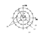
- FIG. 1 shows a diagram for explaining the outline of the technology disclosed in Patent Document 1.
- FIG. 1 shows a constellation corresponding to 32APSK.
- 32APSK 32 symbols indicated by ⁇ or ⁇ in the figure are defined by changing the amplitude and phase of the transmission signal. More specifically, four symbols are defined on the first inner circumference 10, twelve symbols on the second inner circumference 12, and sixteen symbols on the outermost circumference 14.
- Patent Document 1 discloses arranging one or more pilot signals 16 on each of the first inner circumference 10, the second inner circumference 12, and the outermost circumference 14.
- the position of the pilot signal 16 is shared by the transmitter and receiver. Therefore, the receiving device can detect the phase shift occurring in each concentric circle based on the shift between the position of the actually received pilot signal 16 and the position shared in advance.
- the phase shift occurring in the first inner circumference 10 is reflected in that signal. Even when a signal belonging to another concentric circle is received, the phase shift is corrected in the same manner. According to such a method, even if a phase shift occurs in the received signal in a region of high transmission power, the shift can be properly corrected to prevent erroneous transmission of data.
- Non-Patent Document 1 solves the problem of distortion by abandoning the use of the nonlinear region of the amplifier. In other words, with this technique, the amplifier cannot fully demonstrate its inherent ability, and a situation arises that goes against the essential demand of using large power without excessive capital investment.
- the transmitting device needs to transmit at least as many pilot signals as the number of concentric circles forming the constellation to the receiving device.
- the environment of the communication path of the radio signal is not always constant. Therefore, the pilot signal should be executed frequently, preferably for each flow of data communication.
- Patent Document 1 further requires transmission of a larger number of pilot signals when, for example, QAM (Quadrature Amplitude Modulation) is used as the modulation scheme. That is, as described in Patent Document 1, if the modulation scheme is APSK, a plurality of symbols arranged on concentric circles can be corrected with one common phase shift. Therefore, one pilot signal is required for a plurality of symbols arranged on concentric circles.
- QAM Quadrature Amplitude Modulation
- Patent Document 1 enables the use of large power commensurate with the performance of the amplifier, but still leaves room for improvement in terms of data rate.
- the present disclosure has been made in view of the above problems, and aims to provide a wireless communication system that utilizes the nonlinear region of an amplifier, prevents erroneous transmission of data, and secures a high data rate.
- the first purpose is to provide a wireless communication system that utilizes the nonlinear region of an amplifier, prevents erroneous transmission of data, and secures a high data rate.
- a second object of the present disclosure is to provide a wireless communication method that utilizes the nonlinear region of the amplifier, prevents erroneous transmission of data, and secures a high data rate.
- a third object of the present disclosure is to provide a receiver that ensures a high data rate without misidentifying data even when a signal that utilizes the nonlinear region of an amplifier is transmitted. .
- a first aspect is a wireless communication system comprising a transmitting device and a receiving device that perform wireless communication using a single-carrier multi-level modulation scheme,
- the transmitting device Equipped with a transmission signal amplifier with variable transmission power, a process of providing the receiver with specifications relating to the input/output characteristics of the transmit signal amplifier; and a process of providing the receiving device with the transmission power used for data transmission,
- the receiving device A signal point estimation process for estimating a constellation of signal points based on the transmission power and the specification; A process of detecting a reception point, which is a point on constellation coordinates, of a received signal; a process of calculating the likelihood of the reception point with the signal point; and a process of identifying the symbol intended by the receiving point based on the calculated likelihood.
- a second aspect is a wireless communication method using a transmitting device and a receiving device that perform wireless communication using a single-carrier multilevel modulation system
- the transmission device comprises a transmission signal amplifier with variable transmission power, the transmitting device providing the receiving device with specifications regarding the input/output characteristics of the transmit signal amplifier; the transmitting device providing transmission power used for data transmission to the receiving device; the receiving device estimating a constellation of signal points based on the transmission power and the specification; a step in which the receiving device detects a receiving point, which is a point on constellation coordinates, of the received signal; the receiving device calculating the likelihood of the receiving point with the signal point; the receiving device identifying a symbol intended by the receiving point based on the likelihood calculation result; should be included.
- a third aspect is a receiving apparatus for performing wireless communication using a single-carrier multilevel modulation scheme, A process of acquiring specifications regarding input/output characteristics of a transmission signal amplifier used by the transmission device from the transmission device for wireless communication; a process of acquiring the transmission power used by the transmission device for data transmission; A signal point estimation process for estimating a constellation of signal points based on the transmission power and the specification; A process of detecting a reception point, which is a point on constellation coordinates, of a received signal; a process of calculating the likelihood of the reception point with the signal point; a process of identifying a symbol intended by the receiving point based on the calculated likelihood; should be configured to run
- the receiving device can estimate the constellation of signal points based on the transmission power provided by the transmitting device and the specifications of the transmission signal amplifier. Therefore, according to this aspect, it is possible to ensure a high data rate without causing erroneous transmission of data while utilizing the nonlinear region of the amplifier.
- FIG. 1 is a diagram for explaining an overview of the technology disclosed in Patent Document 1;
- FIG. 1 is a diagram for explaining a configuration of a radio communication system according to Embodiment 1 of the present disclosure;
- FIG. FIG. 2 is a diagram for explaining the configuration of a transmission device to be compared with the transmission device according to Embodiment 1 of the present disclosure;
- FIG. 4 is a diagram showing input/output characteristics of an amplifier built into the transmission device;
- FIG. 4 is a diagram showing how distortion occurs in a constellation as transmission power increases.
- 2 is a block diagram for explaining the configuration of a transmission device according to Embodiment 1 of the present disclosure;
- FIG. 2 is a block diagram for explaining the configuration of main parts of a receiving device according to Embodiment 1 of the present disclosure;
- FIG. 4 is a diagram for explaining a characteristic operation of a receiving device according to Embodiment 1 of the present disclosure
- FIG. FIG. 4 is a diagram for explaining a configuration of a communication device included in a radio communication system according to Embodiment 2 of the present disclosure
- FIG. FIG. 10 is a flowchart for explaining the flow of processing executed by the communication device shown in FIG. 9 to control transmission power
- FIG. FIG. 10 is a flowchart for explaining a modified example of processing executed by the communication device shown in FIG. 9 to control transmission power
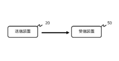
- FIG. 2 shows the overall configuration of a radio communication system according to Embodiment 1 of the present disclosure.
- the wireless communication system of this embodiment includes a transmitting device 20 and a receiving device 50.
- the wireless communication system of this embodiment includes a transmitting device 20 and a receiving device 50.
- FIG. 3 is a block diagram for explaining the configuration of the transmission device 22 to be compared with the transmission device 20 in this embodiment.
- the transmission device 22 of the comparative example includes an information bit generator 24 .
- the information bit generator 24 generates information bits to be transmitted to the receiving device 50 .
- the information bit generator 24 may have an error correction coding function or an interleave function.
- the information bits generated by the information bit generating section 24 are provided to the data signal modulating section 26 .
- the data signal modulator 26 modulates the provided information bits into a data signal.
- the modulation method for example, quadrature amplitude modulation (QAM) or APSK, which can be used for a single-carrier multilevel modulation method, can be considered.
- the data signal generated by the data signal modulating section 26 is provided to the digital-to-analog converting section 28 .
- the digital-to-analog converter 28 converts the digital-modulated data signal into an analog transmission signal.
- the transmission signal generated by the digital-to-analog converter 28 is provided to the transmission signal amplifier 30 .
- the transmission signal amplifier 30 amplifies the transmission signal and provides it to the antenna 32 . Then, the transmission signal is transmitted from the antenna 32 toward the receiving device 50 in the form of a radio signal.
- FIG. 4 shows the input/output characteristics of the transmission signal amplifier 30.
- the output power (vertical axis) of the transmission signal amplifier 30 is proportional to the input power in a region where the input power (horizontal axis) is smaller than PB . Then, in the region where the input power exceeds PB , the proportional relationship is lost.
- a region in which the two are in a proportional relationship will be referred to as a "linear region”
- a region in which the proportional relationship between the two will be lost will be referred to as a "nonlinear region”.
- 64 symbols arranged in a lattice are defined by changing and adjusting the amplitudes of two mutually independent carriers.
- a point on the constellation coordinates where each of these 64 symbols is defined is hereinafter referred to as a "signal point”.
- a point on the constellation coordinates of each data signal that is actually transmitted is called a "receiving point”.
- the reception points form a distortion-free constellation, as shown on the left side of FIG. 5 (transmission power P 1 ).
- transmission power P 1 transmission power
- transmission power P N transmission power
- the receiving device 50 performs likelihood calculation with respect to adjacent signal points for each reception point included in the transmission signal, and recognizes each reception point as one of 64 symbols based on the result.
- the likelihood calculation can be performed, for example, by the method described in the following document.
- the receiving device 50 performs the above-described likelihood calculation using signal points forming a distortion-free constellation, the receiving points generated in the linear domain can be correctly recognized. However, reception points generated in the nonlinear region cannot be recognized correctly because they are shifted from their original positions on the constellation. Therefore, if the transmission signal amplifier 30 uses the non-linear region, data may be misidentified in the receiving device 50 .
- FIG. 6 is a block diagram for explaining the configuration of the transmission device 20 in this embodiment.
- the same elements as those of the transmitting device 22 of the comparative example are denoted by the same reference numerals, and description thereof will be omitted or simplified.
- the information bit generation section 24 in the transmission device 22 of the comparative example is replaced with an information bit generation section 34 .
- the information bit generation unit 34 included in the present embodiment generates information bits regarding the specifications of the transmission device 20 at the stage when communication between the transmission device 20 and the reception device 50 is started. Specifically, the modulation scheme used by the transmitter 20 and the input/output characteristics of the transmission signal amplifier 30 (see FIG. 4) are converted into information bits.
- the information bits generated in this manner are transmitted from the transmitting device 20 to the receiving device 50 when communication between the transmitting device 20 and the receiving device 50 is started. Therefore, in the present embodiment, the modulation method used by the transmission device 20 and the input/output characteristics of the transmission signal amplifier 30 are shared between the two at the time the communication between the two starts.
- the transmission device 20 in this embodiment includes a transmission power control section 36 at the front stage of the transmission signal amplifier 30 .
- the transmission power control unit 36 controls transmission power so as to obtain desired communication quality.
- the transmission power command from the transmission power control unit 36 is provided to the transmission signal amplifier 30 and also to the transmission power information notification unit 38 .
- the transmission power information notification unit 38 provides the information bit generation unit 34 with the transmission power command value. Then, the information bit generator 34 generates bit information about the current transmission power and includes the information in the transmission data. As a result, a transmission signal including information on the transmission power is transmitted from the transmission device 20 of the present embodiment to the reception device 50 at the transmission power set by the transmission power control unit 36 .
- the transmission device 20 of the present embodiment also transmits a training signal when transmitting data after starting communication.
- FIG. 6 shows the data and training signal constellations before and after amplification. If the transmission signal amplifier 30 uses a non-linear region, the constellation of data after amplification will be distorted, as shown in this figure.
- the training signal information is shared in advance between the transmitting device 20 and the receiving device 50, and is preferably transmitted with power (amplitude) within the linear region of the transmission signal amplifier 30.
- the training signal may have phase and amplitude deviations due to the environment of the communication path of the radio signal.
- the receiving device 50 detects the influence of the deviation caused by the communication path based on the deviation between the actually received training signal reception point and the known signal point of the training signal. Then, the receiving device 50 eliminates the influence caused by the communication path by reflecting the detection result on each of the data receiving points.
- FIG. 7 is a block diagram for explaining the configuration of the main part of the receiving device 50 in this embodiment.
- the receiver 50 of this embodiment includes a data signal equalizer 52 .
- the data signal equalizer 52 is a block that obtains an estimated value of the transmission signal by back-calculating the amplitude and phase shift information of the channel response.
- the data signal equalization unit 52 performs a process of reflecting the training result 56 on the data signal 54 .
- a reception point 58 is obtained in which deviations caused by the environment of the communication path are cancelled.
- the receiving device 50 of the present embodiment further includes a likelihood calculating section 60.
- the likelihood calculator 60 is a block that calculates the likelihood according to the current constellation information.
- the likelihood calculator 60 first identifies the constellation 66 of the received signal based on the specification information 62 of the transmitter 20 acquired at the start of communication and the current transmission power 64 received together with the data signal.
- FIG. 8 is a diagram for explaining the outline of the likelihood calculation 68.
- the left side of FIG. 8 outlines the likelihood calculation 68 when the transmit power is P1 .
- the constellation 66 of the received signal has no distortion in which the respective signal points 70 are properly arranged in a grid.
- the likelihood calculator 60 refers to the constellation 66 and calculates the likelihood of some of the signal points 70 located near the reception point 58 using a normal distribution for the Euclidean distance between them. Then, the signal point 70 with the highest likelihood is adopted as the symbol corresponding to the receiving point 58 .
- the right side of FIG. 8 outlines the likelihood calculation 68 when the transmit power is P N .
- the constellation 66 of the received signal includes a shift caused by the nonlinearity of the transmitted signal amplifier 30 at each of the signal points 70 .
- the likelihood calculator 60 refers to the constellation 66 with the shift and calculates the likelihood of the receiving point 58 by the same technique as described above. Then, based on the result, the symbol that the reception point 58 means is specified.
- the transmission device 20 can use the nonlinear region of the transmission signal amplifier 30 to transmit a high-power transmission signal. Also, by passing the specifications of the transmission signal amplifier 30 to the receiving device 50 at the start of communication, the distorted constellation corresponding to the nonlinear region can be reproduced in the receiving device 50 without the need for subsequent provision of information. can be made Then, by executing likelihood calculation using the constellation, it is possible to prevent misidentification of data even for a transmission signal using a nonlinear region. In addition, the extremely small amount of training signal for each data transmission eliminates the effects of channel-induced phase and amplitude shifts at all receiving points. Therefore, according to the wireless communication system of the present embodiment, it is possible to utilize the nonlinear region of the transmission signal amplifier 30, prevent erroneous transmission of data, and secure a high data rate.
- FIG. 7 above shows how the likelihood calculator 60 reproduces the received signal constellation for a plurality of transmission powers P 1 and P 2 belonging to the linear region of the transmission signal amplifier 30 .
- the method of reproducing the constellation of received signals is not limited to this. That is, the likelihood calculation section 60 commonly uses the same distortion-free constellation for the transmission power belonging to the linear region of the transmission signal amplifier 30, and only for the transmission power belonging to the nonlinear region, the constellation of the received signal. ration may be played.
- the transmission device 20 provides the specifications of the transmission signal amplifier 30 to the reception device 50 at the start of wireless communication.
- the present disclosure is not so limited.
- the transmitting device 20 may store the receiving device 50 that has provided the specifications, and the receiving device 50 that has received the specifications may store the information. Then, for the second and subsequent communications between the two, the transmission and reception of the above specification may be omitted.
- the transmission device 20 provides the reception device 50 with the specifications of the transmission signal amplifier 30 as well as information on the modulation scheme used for wireless communication.
- the present disclosure is not so limited. For example, if the modulation scheme used for communication between the transmitting device 20 and the receiving device 50 is determined in advance, providing the information on the modulation scheme can be omitted.
- Embodiment 2 Next, a wireless communication system according to Embodiment 2 of the present disclosure will be described with reference to FIGS. 9 to 11 together with FIG. 2 described above.
- FIG. 9 is a block diagram for explaining the configuration of the communication device 80 used in the wireless communication system of this embodiment.
- the communication device 80 shown in FIG. 9 includes a transmitter for transmitting radio signals and a receiver for processing the received radio signals.
- Communication device 80 can be used as either transmitting device 20 or receiving device 50 shown in FIG. A case where both the transmitting device 20 and the receiving device 50 are configured by the communication device 80 shown in FIG. 9 will be described below.
- a communication device 80 according to the present embodiment includes a transmission section having a configuration similar to that of the transmission device 20 according to the first embodiment. Further, communication apparatus 80 includes data signal equalization section 52 and likelihood calculation section 60, like receiving apparatus 50 of the first embodiment.
- FIG. 9 the same elements as those described in Embodiment 1 are denoted by the reference numerals shown in FIG. 6 or 7, and overlapping descriptions are omitted or simplified.
- the communication device 80 in this embodiment provides the received signal amplifier 82 with the signal received by the antenna 32 .
- the received signal amplifier 82 amplifies the received signal with an appropriate gain and provides it to the analog-to-digital converter 84 .
- the analog-to-digital conversion unit 84 is a block for demodulating an analog received signal into a digital signal.
- the signal digitized by the analog-to-digital converter 84 is provided to the data signal equalizer 52 .
- the data signal equalization unit 52 and the likelihood calculation unit 60 perform the same processing as in the first embodiment. This provides accurate data recognition regardless of whether the received signal constellation contains distortion or not.
- the signal symbolized by the likelihood calculation unit 60 is provided to the information bit detection unit 86 .
- the information bit detector 86 converts information about the signal error rate BER (Bit Error Rate) into bits in addition to the data to be exchanged with the communication partner.
- the BER information is then provided to the information bit generator 34 of the transmitter.
- the information bit generation unit 34 performs bit generation processing so that the information is included in the transmission signal.
- the communication device 80 provides the communication device 80 of the communication partner with information on the BER realized by the current transmission power.
- the communication device 80 shown in FIG. 9 is also provided with information on the BER realized with the current transmission power from the communication partner. This information is restored to a data signal by the receiving section of the communication device 80 and then fed back to the transmission power control section 36 of the transmitting section. Based on the information thus fed back, the transmission power control unit 36 controls transmission power so as to improve communication quality.
- FIG. 10 is a flowchart for explaining an example of processing executed by the transmission power control unit 36 in this embodiment.
- the routine shown in FIG. 10 is started immediately after the communication device 80 establishes communication with the communication device 80 of the other party.
- the transmission power is set to the maximum power P N (step 100).
- a threshold value for example, 1E-6 with respect to the set transmission power (step 102).
- the maximum power PN is the most advantageous power for obtaining excellent SNR if the constellation distortion caused by the nonlinearity of the transmission signal amplifier 30 can be properly absorbed. If it is determined in step 102 that the BER is equal to or less than the threshold, it can be determined that the transmission signal has been received sufficiently accurately. Therefore, in this case, it can be determined that the distortion of the constellation is appropriately absorbed in the communication device 80 of the communication partner. That is, it can be determined that the current transmission power is the maximum power that achieves the desired communication quality.
- Such transmission power is suitable for ensuring a high data rate and a high SNR. Therefore, if the determination in step 102 is affirmative, it is determined that the current transmission power is appropriate, and the power control routine ends.
- the transmission power control unit 36 attempts to reduce the transmission power in order to alleviate distortion of the constellation (step 104). For example, if the current transmit power is P N , the power is changed to P N ⁇ 1 .
- step 102 is executed again. Then, as a result of repeating steps 102 and 104, when the transmission power that clears the BER is found, this routine ends at that point.
- the transmission power used by the communication device 80 is determined to be the highest power that clears the BER after communication starts. Therefore, according to the wireless communication system of this embodiment, in addition to the same effects as in the case of the first embodiment, it is possible to obtain the effect of realizing the best communication quality by optimizing the transmission power. can be done.
- FIG. 11 is a flow chart for explaining an example of another routine that the transmission power control section 36 can execute instead of the routine shown in FIG. 10 in order to control the transmission power. Similarly to the routine shown in FIG. 10, the routine shown in FIG. 11 is also started immediately after the communication device 80 establishes communication with the communication device 80 of the other party.
- the transmission power is first set to the preset initial power (step 110).
- the initial power is the expected maximum power that clears the BER.
- step 112 it is determined whether or not the BER provided by the communication device 80 of the communication partner satisfies the condition of being equal to or lower than the threshold (step 112). This process is substantially the same as the process of step 102 shown in FIG.
- step 112 If it is determined in step 112 that the BER condition has been cleared, it can be determined that there is still room to increase the transmission power. Therefore, in this case, the transmission power control unit 36 attempts to increase the transmission power (step 114). Specifically, the transmission power is changed from the current power P i to P i+1 , which is one step higher.
- step 116 it is determined again whether the BER provided by the communication device 80 of the communication partner satisfies the threshold condition. As a result, if the BER is cleared, the process of step 114 is executed again.
- step 116 determines whether the transmission power has exceeded the upper limit of power that can clear the BER by one step at that point. In this case, it can be determined that power that is one step lower than the current transmission power is the maximum power that clears the BER. Therefore, if the determination in step 116 is negative, the transmission power is lowered by one step (step 118), and the current routine ends.
- step 112 If it is determined in step 112 above that the BER cannot be cleared with the initial power set as the transmission power, a process of lowering the transmission power is executed (step 120). Then, it is determined whether or not the BER for the changed transmission power meets the threshold condition (step 122).
- step 122 determines that the transmission power is still excessive. Therefore, when the determination of step 122 is negative, the process of step 120 is executed again.
- step 122 if the determination in step 122 is affirmative, it can be determined that the transmission power has been reduced to the maximum power that can clear the BER at that time. In this case, since the current transmission power is the optimum power, the current routine is terminated immediately thereafter.
- the transmission power can be set to the maximum power that satisfies the desired BER, as with the routine shown in FIG. Furthermore, according to the routine shown in FIG. 11, when the optimum transmission power is sufficiently smaller than the maximum power PN, the optimum transmission power can be found earlier than the routine shown in FIG. can.
- transmission device 20 transmission device 30 transmission signal amplifier 34 information bit generation unit 36 transmission power control unit 38 transmission power information notification unit 50 reception device 52 data signal equalization unit 60 likelihood calculation unit 80 communication device 86 information bit detection unit
Landscapes
- Engineering & Computer Science (AREA)
- Computer Networks & Wireless Communication (AREA)
- Signal Processing (AREA)
- Quality & Reliability (AREA)
- Transmitters (AREA)
Abstract
Description
前記送信装置は、
送信電力が可変の送信信号増幅器を備え、
前記送信信号増幅器の入出力特性に関する仕様を前記受信装置に提供する処理と、
データ送信に用いている送信電力を前記受信装置に提供する処理と、を実行するように構成されており、
前記受信装置は、
前記送信電力と前記仕様とに基づいて、信号点のコンスタレーションを推定する信号点推定処理と、
受信信号の、コンスタレーション座標上の点である受信点を検知する処理と、
前記受信点について、前記信号点との尤度を計算する処理と、
前記尤度の計算結果に基づいて前記受信点が意図するシンボルを特定する処理と、を実行するように構成されていることが望ましい。
前記送信装置は、送信電力が可変の送信信号増幅器を備え、
前記送信装置が、前記送信信号増幅器の入出力特性に関する仕様を前記受信装置に提供するステップと、
前記送信装置が、データ送信に用いている送信電力を前記受信装置に提供するステップと、
前記受信装置が、前記送信電力と前記仕様とに基づいて、信号点のコンスタレーションを推定するステップと、
前記受信装置が、受信信号の、コンスタレーション座標上の点である受信点を検知するステップと、
前記受信装置が、前記受信点について、前記信号点との尤度を計算するステップと、
前記受信装置が、前記尤度の計算結果に基づいて前記受信点が意図するシンボルを特定するステップと、
を含むことが望ましい。
前記無線通信の送信装置から、当該送信装置が用いる送信信号増幅器の入出力特性に関する仕様を取得する処理と、
前記送信装置がデータ送信に用いている送信電力を取得する処理と、
前記送信電力と前記仕様とに基づいて、信号点のコンスタレーションを推定する信号点推定処理と、
受信信号の、コンスタレーション座標上の点である受信点を検知する処理と、
前記受信点について、前記信号点との尤度を計算する処理と、
前記尤度の計算結果に基づいて前記受信点が意図するシンボルを特定する処理と、
を実行するように構成されていることが望ましい。
[実施の形態1の全体構成]
図2は、本開示の実施の形態1の無線通信システムの全体構成を示す。図2に示すように、本実施形態の無線通信システムは、送信装置20と受信装置50を備えている。
図3は、本実施形態における送信装置20と対比される比較対象の送信装置22の構成を説明するためのブロック図である。比較例の送信装置22は、情報ビット生成部24を備えている。情報ビット生成部24は、受信装置50に伝送したい情報ビットを生成する。情報ビット生成部24は、誤り訂正符号化機能、或いはインターリーブ機能を備えていてもよい。
比較例の送信装置22によっても、送信電力を、送信信号増幅器30の線形領域に制限すれば、データの誤認は防ぐことができる。しかし、その場合、送信信号増幅器30の増幅能力を十分に活用できないという事態が生ずる。
ところで、上記の図7には、尤度算出部60が、送信信号増幅器30の線形領域に属する複数の送信電力P1、P2対して受信信号のコンスタレーションを夫々再生する様子が示されている。しかしながら、受信信号のコンスタレーションを再生する手法はこれに限定されるものではない。すなわち、尤度算出部60は、送信信号増幅器30の線形領域に属する送信電力については、歪みのない同一のコンスタレーションを共通に用いることとし、非線形領域に属する送信電力についてのみ、受信信号のコンスタレーションを再生することとしてもよい。
次に、上記の図2と共に図9乃至図11を参照して、本開示の実施の形態2の無線通信システムについて説明する。
図11は、送信電力制御部36が、送信電力を制御するために、図10に示すルーチンに代えて実行することのできる他のルーチンの例を説明するためのフローチャートである。図11に示すルーチンも、図10に示すルーチンと同様に、通信装置80が、相手方の通信装置80との通信を確立した直後に起動される。
30 送信信号増幅器
34 情報ビット生成部
36 送信電力制御部
38 送信電力情報通知部
50 受信装置
52 データ信号等化部
60 尤度算出部
80 通信装置
86 情報ビット検出部
Claims (8)
- シングルキャリア多値変調方式を用いて無線通信を行う送信装置と受信装置を備える無線通信システムであって、
前記送信装置は、
送信電力が可変の送信信号増幅器を備え、
前記送信信号増幅器の入出力特性に関する仕様を前記受信装置に提供する処理と、
データ送信に用いている送信電力を前記受信装置に提供する処理と、を実行するように構成されており、
前記受信装置は、
前記送信電力と前記仕様とに基づいて、信号点のコンスタレーションを推定する信号点推定処理と、
受信信号の、コンスタレーション座標上の点である受信点を検知する処理と、
前記受信点について、前記信号点との尤度を計算する処理と、
前記尤度の計算結果に基づいて前記受信点が意図するシンボルを特定する処理と、を実行するように構成されている無線通信システム。 - 前記信号点推定処理は、
前記送信電力が前記送信信号増幅器の線形領域に属する場合に、前記シングルキャリア多値変調方式の基準のコンスタレーションを、前記信号点のコンスタレーションとする処理と、
前記送信電力が前記送信信号増幅器の非線形領域に属する場合に、前記送信電力と前記仕様とに対応する歪みを前記基準のコンスタレーションに加えたものを、前記信号点のコンスタレーションとする処理と、
を含む請求項1に記載の無線通信システム。 - 前記送信装置は、
トレーニング信号を送信する処理を更に実行するように構成されており、
前記受信装置は、
前記トレーニング信号の本来の値を記憶しており、
前記本来の値と、現実に受信したトレーニング信号の値との差に基づいて、通信路が前記受信信号に与える影響を検知する処理と、
前記尤度の計算に先立って前記受信点から前記通信路の影響を排除する処理と、を更に実行するように構成されている請求項1または2に記載の無線通信システム。 - 前記トレーニング信号は、前記送信信号増幅器の線形領域に属する電力で送信される請求項3に記載の無線通信システム。
- 前記受信装置は、
受信信号の誤り率を計算する処理と、
前記誤り率を前記送信装置に提供する処理と、を更に実行するように構成されており、
前記送信装置は、
前記送信電力を、前記誤り率に関する要求がクリアされる最大の電力に制御する電力制御処理を更に実行するように構成されている請求項1乃至4の何れか1項に記載の無線通信システム。 - 前記電力制御処理は、
無線通信の開始時に、前記送信電力を最大電力に設定する処理と、
前記受信装置から、前記誤り率を取得する処理と、
前記誤り率が、前記要求をクリアしているか否かを判断する処理と、
前記誤り率が前記要求をクリアしているとの結果が得られるまで、前記送信電力を段階的に減少させる処理と、を含む請求項5に記載の無線通信システム。 - シングルキャリア多値変調方式を用いて無線通信を行う送信装置と受信装置を用いる無線通信方法であって、
前記送信装置は、送信電力が可変の送信信号増幅器を備え、
前記送信装置が、前記送信信号増幅器の入出力特性に関する仕様を前記受信装置に提供するステップと、
前記送信装置が、データ送信に用いている送信電力を前記受信装置に提供するステップと、
前記受信装置が、前記送信電力と前記仕様とに基づいて、信号点のコンスタレーションを推定するステップと、
前記受信装置が、受信信号の、コンスタレーション座標上の点である受信点を検知するステップと、
前記受信装置が、前記受信点について、前記信号点との尤度を計算するステップと、
前記受信装置が、前記尤度の計算結果に基づいて前記受信点が意図するシンボルを特定するステップと、
を含む無線通信方法。 - シングルキャリア多値変調方式を用いて無線通信を行うための受信装置であって、
前記無線通信の送信装置から、当該送信装置が用いる送信信号増幅器の入出力特性に関する仕様を取得する処理と、
前記送信装置がデータ送信に用いている送信電力を取得する処理と、
前記送信電力と前記仕様とに基づいて、信号点のコンスタレーションを推定する信号点推定処理と、
受信信号の、コンスタレーション座標上の点である受信点を検知する処理と、
前記受信点について、前記信号点との尤度を計算する処理と、
前記尤度の計算結果に基づいて前記受信点が意図するシンボルを特定する処理と、
を実行するように構成されている受信装置。
Priority Applications (4)
| Application Number | Priority Date | Filing Date | Title |
|---|---|---|---|
| PCT/JP2021/030455 WO2023021664A1 (ja) | 2021-08-19 | 2021-08-19 | 無線通信システム、無線通信方法および受信装置 |
| US18/683,780 US12388701B2 (en) | 2021-08-19 | 2021-08-19 | Wireless communication system, wireless communication method, and reception apparatus |
| EP21954232.1A EP4391469B1 (en) | 2021-08-19 | 2021-08-19 | Wireless communication system, wireless communication method, and reception apparatus |
| JP2023542134A JP7794203B2 (ja) | 2021-08-19 | 2021-08-19 | 無線通信システム、無線通信方法および受信装置 |
Applications Claiming Priority (1)
| Application Number | Priority Date | Filing Date | Title |
|---|---|---|---|
| PCT/JP2021/030455 WO2023021664A1 (ja) | 2021-08-19 | 2021-08-19 | 無線通信システム、無線通信方法および受信装置 |
Publications (1)
| Publication Number | Publication Date |
|---|---|
| WO2023021664A1 true WO2023021664A1 (ja) | 2023-02-23 |
Family
ID=85240359
Family Applications (1)
| Application Number | Title | Priority Date | Filing Date |
|---|---|---|---|
| PCT/JP2021/030455 Ceased WO2023021664A1 (ja) | 2021-08-19 | 2021-08-19 | 無線通信システム、無線通信方法および受信装置 |
Country Status (4)
| Country | Link |
|---|---|
| US (1) | US12388701B2 (ja) |
| EP (1) | EP4391469B1 (ja) |
| JP (1) | JP7794203B2 (ja) |
| WO (1) | WO2023021664A1 (ja) |
Cited By (2)
| Publication number | Priority date | Publication date | Assignee | Title |
|---|---|---|---|---|
| WO2024176457A1 (ja) * | 2023-02-24 | 2024-08-29 | 日本電信電話株式会社 | 無線通信システム、送信装置、受信装置、無線通信方法、及び無線通信プログラム |
| WO2024176462A1 (ja) * | 2023-02-24 | 2024-08-29 | 日本電信電話株式会社 | 無線通信システム、送信装置、受信装置、無線通信方法、及び無線通信プログラム |
Families Citing this family (1)
| Publication number | Priority date | Publication date | Assignee | Title |
|---|---|---|---|---|
| US20250097851A1 (en) * | 2021-09-03 | 2025-03-20 | Nippon Telegraph And Telephone Corporation | Wireless communication system, wireless communication method, and wireless communication transmission device |
Citations (5)
| Publication number | Priority date | Publication date | Assignee | Title |
|---|---|---|---|---|
| JP2010171905A (ja) * | 2009-01-26 | 2010-08-05 | Nippon Hoso Kyokai <Nhk> | デジタル伝送方式の復号器及び受信装置 |
| JP2012065008A (ja) * | 2010-09-14 | 2012-03-29 | Sony Corp | 受信装置および方法、並びにプログラム |
| JP2015002354A (ja) * | 2013-06-12 | 2015-01-05 | ソニー株式会社 | 送信装置および送信装置の信号送信方法、受信装置および受信装置の信号受信方法、並びにプログラム |
| WO2016012382A1 (en) * | 2014-07-22 | 2016-01-28 | Deutsches Zentrum Fuer Luft- Und Raumfahrt E.V. | Method for receiving a digital signal in a digital communication system |
| JP2017059889A (ja) | 2015-09-14 | 2017-03-23 | 日本放送協会 | シングルキャリア方式の送信装置及び受信装置 |
Family Cites Families (5)
| Publication number | Priority date | Publication date | Assignee | Title |
|---|---|---|---|---|
| US5815531A (en) * | 1996-06-12 | 1998-09-29 | Ericsson Inc. | Transmitter for encoded data bits |
| IT1313906B1 (it) * | 1999-06-15 | 2002-09-26 | Cit Alcatel | Precorrezione digitale adattiva di non-linearita' introdotte daamplicatori di potenza. |
| JP4019912B2 (ja) * | 2002-11-20 | 2007-12-12 | 日本電気株式会社 | ディジタル無線通信システム及びそれに用いる復調器 |
| CN110086736B (zh) * | 2013-04-12 | 2022-09-23 | 太阳专利托管公司 | 发送装置、发送方法、接收装置、接收方法 |
| KR102572878B1 (ko) * | 2018-11-16 | 2023-08-30 | 삼성전자 주식회사 | 공간 재사용을 이용하여 데이터를 전송하는 무선 통신 장치 및 이를 이용한 데이터 통신 방법 |
-
2021
- 2021-08-19 JP JP2023542134A patent/JP7794203B2/ja active Active
- 2021-08-19 WO PCT/JP2021/030455 patent/WO2023021664A1/ja not_active Ceased
- 2021-08-19 EP EP21954232.1A patent/EP4391469B1/en active Active
- 2021-08-19 US US18/683,780 patent/US12388701B2/en active Active
Patent Citations (5)
| Publication number | Priority date | Publication date | Assignee | Title |
|---|---|---|---|---|
| JP2010171905A (ja) * | 2009-01-26 | 2010-08-05 | Nippon Hoso Kyokai <Nhk> | デジタル伝送方式の復号器及び受信装置 |
| JP2012065008A (ja) * | 2010-09-14 | 2012-03-29 | Sony Corp | 受信装置および方法、並びにプログラム |
| JP2015002354A (ja) * | 2013-06-12 | 2015-01-05 | ソニー株式会社 | 送信装置および送信装置の信号送信方法、受信装置および受信装置の信号受信方法、並びにプログラム |
| WO2016012382A1 (en) * | 2014-07-22 | 2016-01-28 | Deutsches Zentrum Fuer Luft- Und Raumfahrt E.V. | Method for receiving a digital signal in a digital communication system |
| JP2017059889A (ja) | 2015-09-14 | 2017-03-23 | 日本放送協会 | シングルキャリア方式の送信装置及び受信装置 |
Non-Patent Citations (3)
| Title |
|---|
| MARVIN K. SIMONRAMESH ANNAVAJJALA: "Optimality of Bit Detection of Certain Digital Modulations", IEEE TRANSACTIONS ON COMMUNICATIONS, vol. 53, no. 2, February 2005 (2005-02-01), pages 299 - 307, XP011127642, DOI: 10.1109/TCOMM.2004.841959 |
| See also references of EP4391469A4 |
| YUANAHMED SAFWAT, PROCEEDINGS OF THE IEEE, vol. 92, no. 2, February 2004 (2004-02-01), pages 312 - 339 |
Cited By (2)
| Publication number | Priority date | Publication date | Assignee | Title |
|---|---|---|---|---|
| WO2024176457A1 (ja) * | 2023-02-24 | 2024-08-29 | 日本電信電話株式会社 | 無線通信システム、送信装置、受信装置、無線通信方法、及び無線通信プログラム |
| WO2024176462A1 (ja) * | 2023-02-24 | 2024-08-29 | 日本電信電話株式会社 | 無線通信システム、送信装置、受信装置、無線通信方法、及び無線通信プログラム |
Also Published As
| Publication number | Publication date |
|---|---|
| EP4391469A4 (en) | 2025-06-18 |
| US12388701B2 (en) | 2025-08-12 |
| EP4391469A1 (en) | 2024-06-26 |
| US20240364572A1 (en) | 2024-10-31 |
| JPWO2023021664A1 (ja) | 2023-02-23 |
| JP7794203B2 (ja) | 2026-01-06 |
| EP4391469B1 (en) | 2026-04-15 |
Similar Documents
| Publication | Publication Date | Title |
|---|---|---|
| Cavers et al. | Adaptive compensation for imbalance and offset losses in direct conversion transceivers | |
| US20030179830A1 (en) | Efficient, high fidelity transmission of modulation schemes through power-constrained remote relay stations by local transmit predistortion and local receiver feedback | |
| WO2023021664A1 (ja) | 無線通信システム、無線通信方法および受信装置 | |
| US8774298B2 (en) | Transmitter with adaptive back-off | |
| EP3320620B1 (en) | Apparatus and method for transmitting and receiving wireless signals subject to spectral mask | |
| JP7647900B2 (ja) | 無線通信システム、無線通信方法、および無線通信用送信装置 | |
| JP7316099B2 (ja) | シングルキャリア方式パラメータの最適値検出装置及びプログラム | |
| JP2018182683A (ja) | シングルキャリア方式の送信装置 | |
| JP7563615B2 (ja) | 無線通信システム、無線通信方法、および無線通信用送信装置 | |
| JP7601239B2 (ja) | 無線通信システム、無線通信方法、集中制御装置、および無線通信用プログラム | |
| WO2023148984A1 (ja) | 無線通信方法、無線通信システムおよび無線送信装置 | |
| WO2023157133A1 (ja) | 無線通信方法、無線通信システム、及び送信装置 | |
| WO2023148954A1 (ja) | 無線通信方法、無線通信システムおよび無線送信装置 | |
| JPWO2011078097A1 (ja) | 複合条件判定ユニット、伝送装置、複合条件判定方法 | |
| JP6668105B2 (ja) | 適応変調送信装置及び適応変調送信方法 | |
| JP7643565B2 (ja) | 無線通信システム、無線通信方法、及び受信装置 | |
| JP3563581B2 (ja) | 無線通信方式 | |
| JP7410519B2 (ja) | 無線通信システム、無線通信方法および送信装置 | |
| JP7746898B2 (ja) | 無線通信方法、無線通信装置、及び無線通信システム | |
| JP3541890B2 (ja) | 復調装置 | |
| JP2861778B2 (ja) | 復調装置 | |
| WO2024171448A1 (ja) | 無線通信システム、受信装置、無線通信方法、及び受信プログラム | |
| JP2007096382A (ja) | 無線通信システムとその送信装置及び受信装置 | |
| EP1418676A1 (en) | Receiver and transceiver for bursty signals | |
| JP4698631B2 (ja) | 通信装置 |
Legal Events
| Date | Code | Title | Description |
|---|---|---|---|
| 121 | Ep: the epo has been informed by wipo that ep was designated in this application |
Ref document number: 21954232 Country of ref document: EP Kind code of ref document: A1 |
|
| WWE | Wipo information: entry into national phase |
Ref document number: 2023542134 Country of ref document: JP |
|
| WWE | Wipo information: entry into national phase |
Ref document number: 2021954232 Country of ref document: EP |
|
| NENP | Non-entry into the national phase |
Ref country code: DE |
|
| ENP | Entry into the national phase |
Ref document number: 2021954232 Country of ref document: EP Effective date: 20240319 |
|
| WWG | Wipo information: grant in national office |
Ref document number: 18683780 Country of ref document: US |
|
| WWG | Wipo information: grant in national office |
Ref document number: 2021954232 Country of ref document: EP |