WO2023021816A1 - 建造物 - Google Patents
建造物 Download PDFInfo
- Publication number
- WO2023021816A1 WO2023021816A1 PCT/JP2022/023328 JP2022023328W WO2023021816A1 WO 2023021816 A1 WO2023021816 A1 WO 2023021816A1 JP 2022023328 W JP2022023328 W JP 2022023328W WO 2023021816 A1 WO2023021816 A1 WO 2023021816A1
- Authority
- WO
- WIPO (PCT)
- Prior art keywords
- heat medium
- flow path
- structural member
- heat
- building according
- Prior art date
- Legal status (The legal status is an assumption and is not a legal conclusion. Google has not performed a legal analysis and makes no representation as to the accuracy of the status listed.)
- Ceased
Links
Images














Classifications
-
- A—HUMAN NECESSITIES
- A01—AGRICULTURE; FORESTRY; ANIMAL HUSBANDRY; HUNTING; TRAPPING; FISHING
- A01G—HORTICULTURE; CULTIVATION OF VEGETABLES, FLOWERS, RICE, FRUIT, VINES, HOPS OR SEAWEED; FORESTRY; WATERING
- A01G9/00—Cultivation in receptacles, forcing-frames or greenhouses; Edging for beds, lawn or the like
- A01G9/24—Devices or systems for heating, ventilating, regulating temperature, illuminating, or watering, in greenhouses, forcing-frames, or the like
- A01G9/243—Collecting solar energy
-
- A—HUMAN NECESSITIES
- A01—AGRICULTURE; FORESTRY; ANIMAL HUSBANDRY; HUNTING; TRAPPING; FISHING
- A01G—HORTICULTURE; CULTIVATION OF VEGETABLES, FLOWERS, RICE, FRUIT, VINES, HOPS OR SEAWEED; FORESTRY; WATERING
- A01G9/00—Cultivation in receptacles, forcing-frames or greenhouses; Edging for beds, lawn or the like
- A01G9/24—Devices or systems for heating, ventilating, regulating temperature, illuminating, or watering, in greenhouses, forcing-frames, or the like
- A01G9/245—Conduits for heating by means of liquids, e.g. used as frame members or for soil heating
-
- E—FIXED CONSTRUCTIONS
- E04—BUILDING
- E04B—GENERAL BUILDING CONSTRUCTIONS; WALLS, e.g. PARTITIONS; ROOFS; FLOORS; CEILINGS; INSULATION OR OTHER PROTECTION OF BUILDINGS
- E04B1/00—Constructions in general; Structures which are not restricted either to walls, e.g. partitions, or floors or ceilings or roofs
- E04B1/62—Insulation or other protection; Elements or use of specified material therefor
- E04B1/74—Heat, sound or noise insulation, absorption, or reflection; Other building methods affording favourable thermal or acoustical conditions, e.g. accumulating of heat within walls
-
- E—FIXED CONSTRUCTIONS
- E04—BUILDING
- E04B—GENERAL BUILDING CONSTRUCTIONS; WALLS, e.g. PARTITIONS; ROOFS; FLOORS; CEILINGS; INSULATION OR OTHER PROTECTION OF BUILDINGS
- E04B1/00—Constructions in general; Structures which are not restricted either to walls, e.g. partitions, or floors or ceilings or roofs
- E04B1/62—Insulation or other protection; Elements or use of specified material therefor
- E04B1/74—Heat, sound or noise insulation, absorption, or reflection; Other building methods affording favourable thermal or acoustical conditions, e.g. accumulating of heat within walls
- E04B1/76—Heat, sound or noise insulation, absorption, or reflection; Other building methods affording favourable thermal or acoustical conditions, e.g. accumulating of heat within walls specifically with respect to heat only
-
- F—MECHANICAL ENGINEERING; LIGHTING; HEATING; WEAPONS; BLASTING
- F24—HEATING; RANGES; VENTILATING
- F24D—DOMESTIC- OR SPACE-HEATING SYSTEMS, e.g. CENTRAL HEATING SYSTEMS; DOMESTIC HOT-WATER SUPPLY SYSTEMS; ELEMENTS OR COMPONENTS THEREFOR
- F24D11/00—Central heating systems using heat accumulated in storage masses
- F24D11/006—Central heating systems using heat accumulated in storage masses air heating system
- F24D11/007—Central heating systems using heat accumulated in storage masses air heating system combined with solar energy
-
- F—MECHANICAL ENGINEERING; LIGHTING; HEATING; WEAPONS; BLASTING
- F24—HEATING; RANGES; VENTILATING
- F24S—SOLAR HEAT COLLECTORS; SOLAR HEAT SYSTEMS
- F24S10/00—Solar heat collectors using working fluids
- F24S10/70—Solar heat collectors using working fluids the working fluids being conveyed through tubular absorbing conduits
- F24S10/72—Solar heat collectors using working fluids the working fluids being conveyed through tubular absorbing conduits the tubular conduits being integrated in a block; the tubular conduits touching each other
-
- F—MECHANICAL ENGINEERING; LIGHTING; HEATING; WEAPONS; BLASTING
- F24—HEATING; RANGES; VENTILATING
- F24S—SOLAR HEAT COLLECTORS; SOLAR HEAT SYSTEMS
- F24S20/00—Solar heat collectors specially adapted for particular uses or environments
- F24S20/60—Solar heat collectors integrated in fixed constructions, e.g. in buildings
- F24S20/66—Solar heat collectors integrated in fixed constructions, e.g. in buildings in the form of facade constructions, e.g. wall constructions
-
- F—MECHANICAL ENGINEERING; LIGHTING; HEATING; WEAPONS; BLASTING
- F24—HEATING; RANGES; VENTILATING
- F24S—SOLAR HEAT COLLECTORS; SOLAR HEAT SYSTEMS
- F24S20/00—Solar heat collectors specially adapted for particular uses or environments
- F24S20/60—Solar heat collectors integrated in fixed constructions, e.g. in buildings
- F24S20/67—Solar heat collectors integrated in fixed constructions, e.g. in buildings in the form of roof constructions
-
- F—MECHANICAL ENGINEERING; LIGHTING; HEATING; WEAPONS; BLASTING
- F24—HEATING; RANGES; VENTILATING
- F24S—SOLAR HEAT COLLECTORS; SOLAR HEAT SYSTEMS
- F24S80/00—Details, accessories or component parts of solar heat collectors not provided for in groups F24S10/00-F24S70/00
- F24S80/30—Arrangements for connecting the fluid circuits of solar collectors with each other or with other components, e.g. pipe connections; Fluid distributing means, e.g. headers
-
- E—FIXED CONSTRUCTIONS
- E04—BUILDING
- E04B—GENERAL BUILDING CONSTRUCTIONS; WALLS, e.g. PARTITIONS; ROOFS; FLOORS; CEILINGS; INSULATION OR OTHER PROTECTION OF BUILDINGS
- E04B1/00—Constructions in general; Structures which are not restricted either to walls, e.g. partitions, or floors or ceilings or roofs
- E04B1/0023—Building characterised by incorporated canalisations
-
- Y—GENERAL TAGGING OF NEW TECHNOLOGICAL DEVELOPMENTS; GENERAL TAGGING OF CROSS-SECTIONAL TECHNOLOGIES SPANNING OVER SEVERAL SECTIONS OF THE IPC; TECHNICAL SUBJECTS COVERED BY FORMER USPC CROSS-REFERENCE ART COLLECTIONS [XRACs] AND DIGESTS
- Y02—TECHNOLOGIES OR APPLICATIONS FOR MITIGATION OR ADAPTATION AGAINST CLIMATE CHANGE
- Y02A—TECHNOLOGIES FOR ADAPTATION TO CLIMATE CHANGE
- Y02A40/00—Adaptation technologies in agriculture, forestry, livestock or agroalimentary production
- Y02A40/10—Adaptation technologies in agriculture, forestry, livestock or agroalimentary production in agriculture
- Y02A40/25—Greenhouse technology, e.g. cooling systems therefor
Definitions
- the present invention relates to buildings.
- Patent Literature 1 discloses an agricultural house in which a heat collecting member is installed. During the daytime, the heat medium heated by irradiating the heat collecting member with sunlight circulates in the farm house at night to heat the air in the farm house.
- the present invention provides a building that collects heat from sunlight while suppressing the increase in the range of shadows that cause a decrease in the amount of sunlight in an agricultural greenhouse and unevenness.
- the present invention comprises at least one structural member, which is formed by extruding or casting a metal, has a light receiving surface on which sunlight is irradiated, and extends from a first end to a second end.
- a structural member main body having an extending hollow portion formed therein; a pair of lid portions arranged at the first end portion and the second end portion to close the hollow portion; and a pair of lid portions.
- a building provided with an inlet provided in either of the lids for allowing a heat medium to flow into the hollow part, and an outlet provided in one of the pair of lid parts for allowing the heat medium to flow out of the hollow part.
- the sunlight irradiated to the light receiving surface of the structural member main body is converted into heat in the structural member main body, and the heat can be stored in the heat medium. That is, the structural member can collect heat from sunlight.
- a structural member is a member essential for building a building with a certain structure and maintaining that structure.
- agricultural greenhouses are constructed so as to minimize the configuration other than structural members and transparent sheets in order to secure the amount of light in the agricultural greenhouse. In other words, it is not desirable to provide a structure other than the structural member and the transparent sheet in the agricultural house because it reduces the amount of solar radiation.
- the structural member can collect heat from the sunlight, it is possible to suppress the installation of another heat collecting member, and it is possible to suppress the decrease in the amount of solar radiation in the agricultural house.
- the hollow portion is arranged so as to be adjacent to a first flow path through which the heat medium flows from the first end toward the second end, and the first flow path via a partition wall.
- a second flow path through which the heat medium flows from the end portion toward the first end portion may be provided.
- the hollow portion since the hollow portion has two channels, the channel through which the heat medium flows becomes longer, and the contact area between the structural member main body and the heat medium can be increased. Therefore, the heat of the structural member main body heated by sunlight can be efficiently transferred to the heat medium.
- Each of the pair of lids is provided with a connection flow path connecting the first flow path and the second flow path so that the heat transfer medium meanders from the inlet to the outlet. may be provided.
- the heat medium flows meanderingly, it is possible to secure a large contact area between the structural member main body and the heat medium.
- the contact time between the structural member main body and the heat medium may increase. Therefore, heat from sunlight can be efficiently stored in the heat medium.
- the lid portion by processing the lid portion to provide a connection channel, a channel in which the heat medium flows meanderingly can be formed. Therefore, the structural member main body can be easily manufactured without processing for forming the meandering flow path in the structural member main body.
- the partition wall may be provided with a liquid passage hole that connects the first flow path and the second flow path so that the heat medium meanders and flows from the inflow port toward the outflow port. good.
- the heat medium flows meanderingly, it is possible to secure a large contact area between the structural member main body and the heat medium.
- the contact time between the structural member main body and the heat medium may increase. Therefore, heat from sunlight can be efficiently stored in the heat medium.
- the structural member main body by processing the structural member main body to provide liquid passage holes, a flow path through which the heat medium flows meanderingly can be formed. Therefore, the lid does not need to be processed to form a meandering flow path, and the lid can be easily manufactured.
- the hollow portion may include a plurality of first flow paths arranged adjacent to each other with partition walls interposed therebetween and through which the heat medium flows from the first end toward the second end.
- the heat transfer medium is branched from the inlet to the plurality of first flow paths, joined from the plurality of first flow paths, and flows toward the outlet.
- a common channel communicating with each of the opening ends of the plurality of first channels may be provided.
- the structural member main body has recesses provided at the first end portion and the second end portion for communicating the ends of the plurality of first flow paths, and each of the pair of lid portions includes: An inflow/outflow channel may be provided for communicating the inflow port or the outflow port with the recess.
- the structural member main body may be provided with ribs along the direction in which the hollow portion extends.
- the provision of the ribs increases the contact area between the structural member main body and the heat medium. Therefore, the heat generated by the sunlight irradiated and converted to the structural member body can be efficiently transferred to the heat medium and stored.
- a black film may be coated on the light receiving surface.
- the emissivity of the light receiving surface can be improved, so the heating efficiency of the heat medium by sunlight can be improved.
- a heat insulating material may be arranged on the outer surface of the structural member excluding the light receiving surface.
- the structural member may be a pillar fixed to the ground and extending in the vertical direction.
- the heating efficiency of the heat medium can be improved during times when the altitude of the sun is low at sunrise or sunset.
- sunlight irradiates the pillar material at a small angle of incidence, so the amount of solar radiation can increase. Therefore, the amount of heat received by the pillar material from the sunlight increases, and the heating efficiency of the heat medium can be improved.
- the structural member may include an embedded portion that extends beyond the ground and is embedded in the ground.
- geothermal heat in addition to heat from sunlight, geothermal heat can be used for heat medium heating.
- the structural members may be beam members extending in the lateral direction.
- the heating efficiency of the heat medium can be improved during the daytime when the sun is located in the south and the altitude of the sun is high.
- the sunlight irradiates the beams at a small angle of incidence, so the amount of solar radiation can increase. Therefore, the amount of heat received by the beam from the sunlight increases, and the heating efficiency of the heat medium can be improved.
- the structural member may be a pair of buttress beam members extending in an oblique direction and connected to each other.
- the heating efficiency of the heat medium can be improved during the daytime when the sun is located in the south and the altitude of the sun is high.
- the sunlight irradiates the joining beams at a small angle of incidence, so the amount of solar radiation can increase. Therefore, the amount of heat that the joining beam member receives from the sunlight increases, and the heating efficiency of the heat medium can be improved.
- the building according to the present invention it is possible to collect heat from sunlight while suppressing an increase in the range of shadows that cause a decrease in the amount of sunlight and unevenness in the agricultural greenhouse.
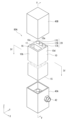
- FIG. 1 is an exploded perspective view of a structural member according to a first embodiment of the present invention
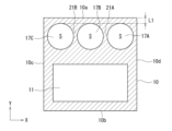
- FIG. 4 is a cross-sectional view taken along line IV-IV of FIG. 3
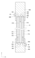
- FIG. 4 is a cross-sectional view taken along line VV of FIG. 3
- FIG. 2 is a partial cross-sectional view taken along line VIII-VIII of FIG. 1;
- FIG. 9 is a partial cross-sectional view similar to FIG. 8;
- FIG. 9 is a partial cross-sectional view similar to FIG. 8;
- Sectional drawing similar to FIG. 4 of the agricultural house in 4th Embodiment of this invention The schematic block diagram of the agricultural house in 5th Embodiment of this invention.
- FIG. 5 The fragmentary sectional view similar to FIG. 5 of the agricultural house in 6th Embodiment of this invention.
- the perspective view of the lid part similar to FIG. 6 of the agricultural house in 6th Embodiment of this invention.
- the perspective view of the lid part similar to FIG. 7 of the agricultural house in 6th Embodiment of this invention.
- FIG. 10 of the agricultural house in 6th Embodiment of this invention The fragmentary sectional view similar to FIG. 12 of the agricultural house in 7th Embodiment of this invention.
- FIG. 5 is a cross-sectional view of a structural member similar to FIG. 4 in a second modification of the invention; Sectional drawing of the structural member similar to FIG. 4 in the 3rd modification of this invention. Sectional drawing of the structural member similar to FIG. 4 in the 4th modification of this invention.
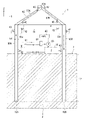
- an agricultural house (building) 1 in this embodiment is a building installed so that the installation area is rectangular with respect to the ground 2.
- the pillar members 80A and 80B, the beam member 81, and the joining beam members 82A and 82B are respectively essential members for maintaining the structure of the farm house 1, and the weight of the farm house 1 and the wind and the like are applied.
- the farm house 1 has rigidity that can withstand a load applied from the outside.
- the pillars 80A and 80B, the beam 81, and the joining beams 82A and 82B are arranged so that the later-described surface (light receiving surface) 10a faces the sun.
- the pillars 80A and 80B, the beam 81, and the joining beams 82A and 82B are arranged so that the surface 10a faces south.
- the heat medium flowing inside each of the pillar members 80A and 80B, the beam member 81, and the joining beam members 82A and 82B is warmed.
- the lateral direction of the farm house 1 parallel to the ground 2 is the X direction
- the longitudinal direction of the farm house 1 parallel to the ground 2 is the Y direction
- the height direction of the farm house 1 perpendicular to the ground 2. be the Z direction.
- Agricultural house 1 is a building that is long in the Y direction in plan view.
- the pillar members 80A and 80B, the beam member 81, and the joining beam members 82A and 82B are provided at a constant pitch in the Y direction and connected by connecting members 83 extending in the Y direction.
- the farming house 1 has a cultivation space 64 and an upper space 65 .
- the cultivation space 64 is a space below the beam 81
- the upper space 65 is a space above the beam 81 .
- the agricultural house 1 includes a tank 58, a pump 59, a controller 60, a three-way valve 62, and a radiator 61.
- one set of tank 58, pump 59, controller 60, three-way valve 62, and radiator 61 is provided for one set of pillar members 80A and 80B, beam member 81, and joining beam members 82A and 82B. is provided.
- a set of tank 58 , pump 59 , controller 60 , three-way valve 62 , and radiator 61 may be provided for the entire agricultural house 1 .
- the tank 58 is connected to the pillar material 80B via a pipe 66a, connected to the pump 59 via a pipe 66b, and connected to the radiator 61 via a pipe 66c.
- the pump 59 is connected to the three-way valve 62 via a pipe 66d.
- the three-way valve 62 is connected to the column member 80A via a pipe 66e, and is connected to the radiator 61 via a pipe 66f.
- the three-way valve 62 is controlled by the control unit 60 to switch between flowing the heat medium flowing from the pipe 66d to the pipe 66e or to the pipe 66f.
- a heat medium is stored in the tank 58.
- the heat medium is pressure-fed by the pump 59 and sent to the pillar material 80A or the radiator 61 via the three-way valve 62 .
- the heat medium is sent to the pillar material 80A, which is the heat collecting part, during the daytime, and is sent to the radiator 61 at nighttime.
- the heat medium sent to the pillar 80A returns to the tank 58 via the beam 81, the joining beams 82A and 82B, and the pillar 80B. Meanwhile, the heat carrier is warmed by sunlight. Also, the heat medium sent to the radiator 61 returns to the tank 58 through the pipe 66c.
- the radiator 61 may be a known one that exchanges heat with a heat medium flowing inside, and may be, for example, a tube that is laid on the ground inside the agricultural house 1 .
- the radiator 61 is arranged in the cultivation space 64.
- the cultivation space 64 and the upper space 65 may be separated by a curtain (not shown).
- the curtain prevents the transfer of heat between the cultivation space 64 and the upper space 65 and improves the heat retention of the cultivation space 64 .
- the configuration of the pillar material 80A will be described with reference to FIG.
- the pillars 80A, 80B, the beam 81, and the joining beams 82A, 82B have the same configuration. The description of each configuration of is omitted.
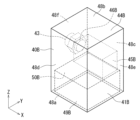
- the pillar 80A includes a pillar body (structural member body) 10 and a pair of lids 40A and 40B.
- the pillar body 10 is an elongated member that is formed by metal extrusion molding or casting, and extends from the first end 15 toward the second end 16 with an arbitrary length.
- the column body 10 is made of an aluminum alloy.
- the pillar body 10 may be made of other metal materials such as steel, aluminum, copper, copper alloys, or silver.
- the thermal conductivity of the pillar body 10 is 200 w/m ⁇ K or more.
- the pillar body 10 has a substantially rectangular cross-section perpendicular to the extending direction, and includes a surface 10a, a surface 10b facing the surface 10a, and surfaces 10c and 10d connecting the surfaces 10a and 10b.
- the surface 10a is irradiated with sunlight.
- a hollow portion 20 and a cavity 11 are formed inside the column body 10 .
- Hollow portion 20 and cavity 11 each extend from first end 15 toward second end 16 and are open at both ends.
- the hollow portion 20 includes two first flow paths 17A and 17C through which the heat medium flows from the first end 15 toward the second end 16, and two first flow paths 17A and 17C through which the heat medium flows. and one second flow path 17B flowing from to the first end 15 .
- the first flow path 17A and the second flow path 17B are arranged adjacent to each other with the partition wall 21A interposed therebetween, and the first flow path 17C and the second flow path 17B are arranged adjacent to each other with the partition wall 21B interposed therebetween.
- Each of the first flow paths 17A, 17C and the second flow path 17B extends parallel to the extending direction of the column body 10 .
- the first channel 17A is arranged on the surface 10d side with respect to the second channel 17B.
- the first flow path 17A has a first opening 18A at the first end 15 and a second opening 19A at the second end 16 .
- the second flow path 17B has a first opening 18B at the first end 15 and a second opening 19B at the second end 16 as well.
- the first channel 17C is arranged on the surface 10c side with respect to the second channel 17B.
- the first flow path 17C has a first opening 18C at the first end 15 and a second opening 19C at the second end 16 as well.
- first flow paths 17A, 17C and the second flow path 17B are arranged on the side of the surface 10a with respect to the cavity 11 and separated from the surface 10a by a distance L1.
- each of the first flow paths 17A, 17C and the second flow path 17B has a circular cross-section perpendicular to the extending direction of the column body 10 and has a constant cross-sectional area S.
- the cavity 11 is arranged on the surface 10b side with respect to the first flow paths 17A, 17C and the second flow path 17B.
- the heat medium does not flow through the cavity 11, which is provided to reduce the weight of the column body 10.
- the shape, position, and size of the cavity 11 are determined so as to reduce the weight of the pillar body 10 while ensuring the cross-sectional performance of the pillar body 10 in a cross section perpendicular to the extending direction of the pillar body 10. is set. Cavity 11 may not be provided.
- a lid portion 40A is fixed to the first end portion 15 of the pillar body 10 so as to close the hollow portion 20.
- a lid portion 40B is fixed to the second end portion 16 of the pillar body 10 so as to close the hollow portion 20 .
- the lids 40A and 40B are formed by cutting an aluminum alloy.
- the lids 40A and 40B may be made of other metal materials such as steel, aluminum, copper, copper alloys, or silver. More preferably, the thermal conductivity of the lids 40A and 40B is 200 w/m ⁇ K or more.
- the lid portion 40A is a rectangular parallelepiped member having a top surface 47a, a bottom surface 47b facing the top surface 47a, and side surfaces 47c, 47d, 47e connecting the top surface 47a and the bottom surface 47b. 47f.
- the top surface 47 a faces the pillar body 10 .
- the side surfaces 47c, 47d, 47e, and 47f extend flush with the surfaces 10a, 10b, 10c, and 10d of the column body 10, respectively.
- the lid portion 40A has a recess portion 41A with a hollow structure and a base portion 44A with a solid structure.
- the recess 41A is provided so as to form an opening 49A in the top surface 47a.
- the base portion 44A is arranged on the side of the bottom surface 47b.
- the side surface 47f is provided with an inlet 42 through which the heat medium flows into the first flow path 17A.
- the shape of the opening 49A of the recess 41A is the same as the outer shape of the cross-sectional shape perpendicular to the extending direction of the pillar body 10, that is, substantially rectangular.
- the first end 15 side of the pillar body 10 is fitted into the recess 41A, and the first end 15 is in close contact with the contact surface 50A of the recess 41A.
- 40 A of cover parts are being fixed to the pillar main body 10 by arbitrary fixing methods, such as welding.
- connection channel 45A is provided in the base portion 44A.
- the connecting channel 45A is a U-shaped channel having openings 51A and 51B at both ends. Aperture 51A is aligned with first aperture 18C and aperture 51B is aligned with first aperture 18B. Therefore, the connection flow path 45A connects the second flow path 17B and the first flow path 17C, and bends the flow direction of the heat medium by 180 degrees.
- an inflow/outflow flow path 46A is provided in the base portion 44A.
- the inflow/outflow channel 46A is a channel having openings 51C and 51D at both ends. Aperture 51C is aligned with first aperture 18A and aperture 51D is aligned with inlet . Therefore, the inflow/outflow channel 46A communicates the first channel 17A and the inflow port 42 with each other.
- the lid portion 40B is a rectangular parallelepiped member having a top surface 48a, a bottom surface 48b facing the top surface 48a, and a side surface 48c connecting the top surface 48a and the bottom surface 48b. , 48d, 48e, 48f.
- the top surface 48 a faces the pillar body 10 .
- the side surfaces 48c, 48d, 48e, and 48f extend flush with the surfaces 10a, 10b, 10d, and 10c of the column body 10, respectively.
- the lid portion 40B has a recess portion 41B with a hollow structure and a base portion 44B with a solid structure.
- the recess 41B is provided to form an opening 49B in the top surface 48a.
- the base portion 44B is arranged on the side of the bottom surface 48b.
- the side surface 48f is provided with an outflow port 43 through which the heat medium flows out from the first flow path 17C.
- the shape of the opening 49B of the recessed portion 41B is the same as the outer shape of the cross-sectional shape perpendicular to the extending direction of the pillar body 10, that is, substantially rectangular.
- the second end 16 side of the pillar body 10 is fitted into the recess 41B, and the second end 16 is in close contact with the contact surface 50B of the recess 41B.
- the lid portion 40B is fixed to the pillar body 10 by any fixing method such as welding.
- connection channel 45B is provided in the base portion 44B.
- the connecting channel 45B is a U-shaped channel having openings 52A and 52B at both ends. Aperture 52A is aligned with second aperture 19A and aperture 52B is aligned with second aperture 19B. Therefore, the connection channel 45B connects the first channel 17A and the second channel 17B, and bends the flow direction of the heat medium by 180 degrees.
- an inflow/outflow passage 46B is provided in the base portion 44B.
- the inflow/outflow channel 46B is a channel having openings 52C and 52D at both ends. Aperture 52C is aligned with second aperture 19C and aperture 52D is aligned with outlet 43 . Therefore, the inflow/outflow channel 46B communicates the first channel 17C and the outflow port 43 .
- the heat medium that has flowed in from the inlet 42 flows into the first flow path 17A through the inflow/outflow flow path 46A of the lid portion 40A, and flows through the first flow path 17A from the first end portion 15 to the first flow path 17A. It flows toward the second end portion 16 and flows into the second flow path 17B via the connection flow path 45B of the lid portion 40B.
- the heat medium that has flowed into the second flow path 17B flows from the second end portion 16 toward the first end portion 15 and flows into the first flow path 17C via the connection flow path 45A of the lid portion 40A.
- the heat medium that has flowed into the first flow path 17C flows from the first end portion 15 toward the second end portion 16, and flows through the inflow/outflow flow path 46B of the lid portion 40B and the outflow port 53 to the outside of the column member 80A. flow out to That is, the heat medium meanders from the inlet 42 toward the outlet 43 through the first flow paths 17A and 17C, the second flow path 17B, the connection flow paths 45A and 45B, and the inflow/outflow flow paths 46A and 46B. and flow.
- the pillar material 80B, the beam material 81, and the joining beam materials 82A and 82B each have the same configuration as the pillar material 80A as described above. That is, in each of the column member 80B, the beam members 81, and the joining beam members 82A and 82B, the heat medium that has flowed in from the inlet 42 flows meanderingly toward the outlet 43. As shown in FIG.
- the column member 80A extends in the Z direction (longitudinal direction) with the lid portion 40A fixed to the ground 2. Further, the column member 80B extends in the Z direction (longitudinal direction) with the lid portion 40B fixed to the ground 2 .
- the beam member 81 extends in the X direction (horizontal direction) so as to connect the lid portion 40B of the pillar member 80A and the lid portion 40A of the pillar member 80B.
- the lid portion 40A of the beam member 81 is fixed to the lid portion 40B of the pillar member 80A, and the lid portion 40B of the beam member 81 is fixed to the lid portion 40A of the pillar member 80B by welding or the like.
- the joining beam member 82A extends obliquely upward toward the center of the agricultural house 1 from the lid portion 40B of the pillar member 80A.
- the joining beam member 82B extends obliquely upward toward the center of the agricultural house 1 from the lid portion 40A of the pillar member 80B.
- the lid portion 40A of the joining beam member 82A is fixed to the lid portion 40B of the column member 80A and the lid portion 40A of the beam member 81 by welding or the like.
- the lid portion 40B of the joining beam member 82B is fixed to the lid portion 40A of the column member 80B and the lid portion 40B of the beam member 81 by welding or the like.
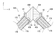
- the lid portion 40B of the joining beam member 82A is connected to the lid portion 40A of the joining beam member 82B.
- the lid portion 40B of the joining beam member 82A is fixed to the lid portion 40A of the joining beam member 82B by welding or the like.
- the ends of the lids 40A and 40B of the joining beams 82A and 82B are inclined, respectively, so that the joining beams 82A and 82B extend obliquely.
- the inflow port 42 of the pillar 80A is connected to the three-way valve 62 via a pipe 66e.
- the outflow port 43 of the pillar member 80A is connected to the inflow port 42 of the beam member 81 and the inflow port 42 of the joining beam member 82A via an external pipe 63a.
- the outlet 43 of the joining beam 82A is connected to the inlet 42 of the joining beam 82B via an external pipe 63b.
- the outflow port 43 of the beam member 81 and the outflow port 43 of the joining beam member 82B are each connected to the inflow port 42 of the column member 80B via an external pipe 63c.
- the outflow port 43 of the pillar material 80B is connected to the tank 58 via the pipe 66a.
- a neutral to weakly alkaline heat medium is used so that the aluminum alloy does not rust.
- a heat medium having a pH of 6 to 11 is used.
- the three-way valve 62 is controlled by the control unit 60, and the heat medium is supplied to the tank 58, the pillars 80A and 80B, the beams 81, and the joining beams 82A. , 82B.
- the heat medium is pressure-fed by the pump 59 from the tank 58 toward the inlet 42 of the column member 80A through the pipes 66b, 66d, 66e and the three-way valve 62.
- the heat medium that has flowed into the pillar member 80A meanders through the inside of the pillar member 80A and flows out from the outflow port 43 of the pillar member 80A.
- the heat medium that has flowed out of the column material 80A flows into the beam material 81 and the joining beam material 82A via the external pipe 63a.
- the heat medium that has flowed into the beam 81 meanders inside the beam 81 and flows out from the outlet 43 of the beam 81 .
- the heat medium flowing into the joining beam 82A meanders inside the joining beam 82A, flows out from the outlet 43 of the joining beam 82A, and flows into the joining beam 82B via the external pipe 63b.
- the heat medium that has flowed into the joining beam member 82B meanders through the inside of the joining beam member 82B and flows out from the outflow port 43 of the joining beam member 82B.
- the heat medium flowing out from the joining beam 82B joins the heat medium flowing out from the beam 81 through the external pipe 63c, and flows into the pillar 80B.
- the heat medium that has flowed into the pillar 80B meanders through the inside of the pillar 80B, flows out from the outlet 43 of the pillar 80B, and returns to the tank 58 via the pipe 66a. During this time, the heat medium is heated by each of the pillars 80A and 80B, the beam 81, and the joining beams 82A and 82B to raise the temperature.
- the three-way valve 62 is controlled by the control unit 60, and the heat medium stored in the tank 58 flows through the radiator 61 so as to circulate.
- the heat medium is pressure-fed by the pump 59 from the tank 58 toward the radiator 61 through the pipes 66 b , 66 d , 66 f and the three-way valve 62 .
- the heated heat medium exchanges heat with the air in the cultivation space 64, and the temperature in the cultivation space 64 rises.
- the heat medium that has been heat-exchanged and cooled by the radiator 61 returns to the tank 58 through the pipe 66c.
- the sunlight irradiated to the surface 10a of the structural member main body 10 is converted into heat in the structural member main body 10, and the heat can be stored in the heat medium. That is, the pillars 80A and 80B, the beam 81, and the joining beams 82A and 82B can each collect heat from sunlight.
- the agricultural house 1 is constructed so as to minimize the configuration other than the structural members and the transparent sheet in order to secure the amount of light in the agricultural house 1 . In other words, it is not desirable to provide the farm house 1 with a structure other than the structural member and the transparent sheet, because this causes a reduction in the amount of solar radiation in the farm house and unevenness.
- the pillars 80A and 80B, the beam 81, and the joining beams 82A and 82B can collect heat from the sunlight, respectively, so that installation of other heat collecting members can be suppressed. It is possible to suppress the increase in the range of shadows, which causes a decrease in the amount of sunlight and unevenness.
- the hollow portion 20 includes the first flow paths 17A and 17C and the second flow path 17B, the flow path for the heat medium becomes longer, and the contact area between the structural member main body 10 and the heat medium can be increased. Therefore, the heat of the structural member main body 10 heated by sunlight can be efficiently transferred to the heat medium.
- the heat medium flows meanderingly, it is possible to secure a large contact area between the structural member main body 10 and the heat medium.
- the contact time between the structural member main body 10 and the heat medium may increase. Therefore, heat from sunlight can be efficiently stored in the heat medium.
- the lid portions 40A and 40B to provide the connection flow paths 45A and 45B, a flow path through which the heat medium flows meanderingly can be formed. Therefore, the structural member main body 10 does not require processing for forming a meandering flow path, and the structural member main body 10 can be easily manufactured.
- the heating efficiency of the heat medium can be improved during the hours when the sun is at sunrise or sunset when the altitude is low.
- sunlight irradiates the pillars 80A and 80B at a small incident angle, so the amount of solar radiation can increase. Therefore, the amount of heat received by the pillar members 80A and 80B from the sunlight increases, and the heating efficiency of the heat medium can be improved.
- the incident angle is the angle formed by the normal line of the surface irradiated with sunlight and the sunlight.
- the heating efficiency of the heat medium can be improved during the daytime when the sun is located in the south and the altitude of the sun is high.
- sunlight irradiates the beam member 81 at a small incident angle, so the amount of solar radiation can increase. Therefore, the amount of heat received by the beam member 81 from sunlight also increases, and the heating efficiency of the heat medium can be improved.
- the heating efficiency of the heat medium can be improved during the daytime when the sun is located in the south and the altitude of the sun is high.
- sunlight irradiates the joining beam members 82A and 82B at a small incident angle, so the amount of solar radiation can increase. Therefore, the amount of heat that the joining beam members 82A and 82B receive from the sunlight increases, and the heating efficiency of the heat medium can be improved.
- the heat medium heated by the sunlight exchanges heat with the radiator 61 and warms the air in the cultivation space 64, so that the inhibition of plant growth due to the temperature drop at night is alleviated, and the growth rate of the plants can be improved.
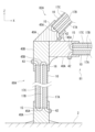
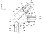
- the agricultural house 1 is provided with a connection lid portion 90.
- the connection lid portion 90 is integrally formed by forming the lid portion 40B of the pillar member 80A, the lid portion 40A of the beam member 81, and the lid portion 40A of the joining beam member 82A as one piece.
- a lid portion flow path 91 is provided inside the connection lid portion 90.
- the lid channel 91 connects the second opening 19C of the pillar member 80A to the first opening 18A of the beam member 81 and the first opening 18A of the joining beam member 82A. Since the external piping 63a is not arranged, the assembly of the agricultural house 1 can be facilitated.
- the pillar member 80A, the beam member 81, and the joining beam member 82A are each fixed to the connection lid portion 90 with screws 92. Therefore, the assembly of the agricultural house 1 can be facilitated.
- the configuration of the agricultural greenhouse 1 according to the second embodiment differs from that of the first embodiment in the following points.
- the rest of the configuration of the second embodiment is the same as that of the first embodiment, and the same reference numerals are given to the same or similar elements as those of the first embodiment.
- the cover portions 40A and 40B are not provided with the connection channels 45A and 45B (shown in FIG. 5), and the column body 10 is provided with the liquid passage holes 22A and 22B.
- the liquid passage hole 22A is provided on the first end portion 15 side of the partition wall 21B that separates the second flow path 17B and the first flow path 17C, and allows the second flow path 17B and the first flow path 17C to communicate with each other.
- the liquid passage hole 22B is provided on the second end portion 16 side of the partition wall 21A that separates the first flow path 17A and the second flow path 17B, and allows the first flow path 17A and the second flow path 17B to communicate with each other.
- the heat medium that has flowed into the pillar body 10 through the inflow port 42 and the inflow/outflow flow path 46A flows through the first flow path 17A from the first end portion 15 toward the second end portion 16, and flows through the liquid passage hole. 22B into the second flow path 17B.
- the heat medium that has flowed into the second flow path 17B flows from the second end 16 toward the first end 15 and flows into the first flow path 17C via the liquid passage holes 22A.
- the heat medium that has flowed into the first flow path 17C flows from the first end 15 toward the second end 16, and flows out of the column body 10 through the inflow/outflow flow path 46B and the outflow port 43. .
- the heat medium meanders from the inflow port 42 toward the outflow port 43 through the first flow paths 17A and 17C, the second flow path 17B, the liquid passage holes 22A and 22B, and the inflow/outflow flow paths 46A and 46B. and flow.
- the heat medium flows meanderingly, a large contact area between the structural member main body 10 and the heat medium can be secured.
- the contact time between the structural member main body 10 and the heat medium may increase. Therefore, heat from sunlight can be efficiently stored in the heat medium.
- the lids 40A and 40B do not need to be processed to form meandering flow paths, and the lids 40A and 40B can be manufactured easily.
- the configuration of the agricultural greenhouse 1 according to the third embodiment differs from that of the first embodiment in the following points.
- Other configurations of the third embodiment are the same as those of the first embodiment, and the same or similar elements as those of the first embodiment are denoted by the same reference numerals.
- the column body 10 is provided with ribs 30 projecting toward the first flow path 17A.
- the rib 30 extends from the first end 15 (shown in FIG. 3) to the second end 16 (shown in FIG. 3) along the extending direction of the column body 10.
- Ribs 30 are similarly provided for each of the second flow path 17B and the first flow path 17C.
- the ribs 30 are integrally formed with the column body 10 by extrusion molding or casting.
- the provision of the ribs 30 increases the contact area between the structural member main body 10 and the heat medium. Therefore, the heat of the sunlight irradiated and converted to the structural member main body 10 can be efficiently transmitted to the heat medium and stored. Further, since the structural member main body 10 is an extruded product or a cast product, a structure having such ribs 30 can be easily formed.
- the configuration of an agricultural house 1 according to the fourth embodiment differs from that of the first embodiment in the following points.
- Other configurations of the fourth embodiment are the same as those of the first embodiment, and the same or similar elements as those of the first embodiment are denoted by the same reference numerals.
- the surface 10a of the pillar body 10 is coated with a black film 36.
- the black film 36 is, for example, a high emissivity film made by electrolytically treating an aluminum alloy, and absorbs light of almost all wavelengths of sunlight.
- heat insulating materials 37A, 37B, and 37C are arranged on the outer surface 38 of the pillar body 10 excluding the surface 10a.
- the heat insulating material 37A is arranged so as to be in contact with the surface 10b
- the heat insulating material 37B is arranged so as to be in contact with the surface 10c
- the heat insulating material 37C is arranged so as to be in contact with the surface 10d.
- the emissivity of the surface 10a can be improved, so the heating efficiency of the heat medium by sunlight can be improved.
- the heat insulating materials 37A to 37C are provided, it is possible to suppress or prevent the heated heat medium or the heat of the structural member main body 10 from being released to the atmosphere. Therefore, the heating efficiency of the heat medium can be improved.
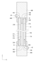
- the pillar member 80A includes an embedded portion 12A that extends beyond the ground 2 and is embedded in the ground 4. Also, the pillar member 80B has an embedded portion 12B that extends beyond the ground surface 2 and is embedded in the ground 4. As shown in FIG.
- the length L2 of the embedded portions 12A and 12B is arbitrary, but is preferably 10 m or longer.
- the inlet 42 of the pillar 80A is not provided in the lid portion 40A, but is provided above the ground 2 of the pillar body 10.
- the lid portion 40A does not have an inflow/outflow flow path 46A (shown in FIG. 5). That is, the first opening 18A of the first flow path 17A is closed by the lid portion 40A. Therefore, when the heat medium is circulating in the farmhouse 1, the heat medium is accumulated between the first end 15 and the inlet 42 in the first flow path 17A of the pillar member 80A. does not flow. The heat medium that has flowed into the column member 80A flows from the inlet 42 toward the second end 16 through the first flow path 17A.
- the column material 80B has the same configuration. That is, between the second end 16 and the outflow port 43 of the first flow path 17C of the column member 80B, the heat medium is accumulated and does not flow. The heat medium that has flowed into the column member 80B flows from the first end 15 toward the outlet 43 through the first flow path 17C.
- the farm house 1 in addition to the heat from the sunlight, it is possible to use geothermal heat obtained through the buried portions 12A and 12B as a heat medium. Especially in winter, since the underground temperature is higher than the air temperature, the inside of the agricultural house 1 can be warmed by utilizing the underground heat.
- the post material main body 10 has the same structure as in the first embodiment (see FIGS. 3 and 4), while the pair of lid parts 40A and 40B are the same as those in the first embodiment. have different structures. Therefore, the channel structure of the heat medium in the column member 80A is also different from that of the first embodiment.
- a common flow path 45A and an inflow/outflow flow path 46A are provided in the base portion 44A of the lid portion 40A.
- 45 A of common flow paths are comprised by the groove
- the opening 51D of the inlet/outlet channel 46A is aligned with the inlet 42 as in the first embodiment, while the opening 51C is open to the common channel 45A.
- the lid portion 40B is configured similarly to the lid portion 40A.
- a common flow path 45B and an inflow/outflow flow path 46B are provided in the base portion 44B of the lid portion 40B.
- the common flow path 45B is configured by a groove recessed from the contact surface 50B of the recess 41B toward the bottom surface 48b.
- the opening 52D of the inlet/outlet channel 46B is aligned with the outlet 43 as in the first embodiment, while the opening 52C is open to the common channel 45B.
- the first end 15 of the pillar body 10 is fitted into the recess 41A of the lid 40A and contacts the abutment surface 50A, and the second end 16 of the pillar body 10 is It is fitted into the recessed portion 41B of the lid portion 40B and comes into contact with the contact surface 50B.
- the hollow portion 20 of the pillar body 10 is composed of three elongated holes arranged adjacent to each other with partition walls 21A and 21B interposed therebetween, and each elongated hole is a first opening opened at a first end 15. 18D, 18E, 18F and second openings 19D, 19E, 19F open at the second end 16 . All of the first openings 18D, 18E, 18F communicate with the common flow path 45A of the lid portion 40A. All of the second openings 19D, 19E, 19F communicate with the common flow path 45B of the lid portion 40B.
- the heat medium that has flowed in from the inflow port 42 flows into the common flow path 45A through the inflow/outflow flow path 45A of the lid portion 40A.
- the heat medium flows from the common flow path 44A into the three slots through the three first openings 18D, 18E, 18F.
- the heat medium flows from the first end 15 toward the second end 16 in each of the three elongated holes. That is, each of these elongated holes serves as the first flow paths 17D, 17E, 17F that flow the heat medium from the first end portion 15 toward the second end portion 16.
- the heat medium in each of the first flow paths 17D, 17E, 17F joins in the common flow path 45B of the lid portion 40B via the second openings 19D, 19E, 19F.
- the heat medium flows from the common flow path 45B through the inflow/outflow flow path 46B toward the outflow port 42 and out of the outflow port 42 .
- the pillar member 40 extends from the second end 16 where the outflow port 43 is arranged to the first end 15 where the inflow port 42 is arranged. It does not have a second channel (for example, the channel 17B shown in FIG. 5) for flowing the heat medium toward the .
- the hollow portion 20 of the pillar body 10 is a plurality of first flow paths 17D, 17E, 17F connected in parallel to the common flow paths 44A, 45B. The heat medium is divided into these first flow paths 17D, 17E, and 17F and flows in one direction from the first end portion 15 toward the second end portion 16. As shown in FIG.
- beams 81 and joining beams 82A and 82B are the same as above.
- the beam member 81 and the joining beam members 82A, 82B also have first flow paths 17D, 17E, 17F through which the heat medium flows in one direction from the first end portion 15 toward the second end portion 16. As shown in FIG.
- the plurality of first flow paths are connected in parallel and the heat medium flows in one way, it is easy to secure the flow rate of the heat medium.
- the flow rate increases, it becomes possible to lower the room temperature with the heat medium when the room temperature rises excessively, and it can be used as an auxiliary device for cooling equipment.
- the residence time of the heat medium is shortened, the load on the pump 59 can be reduced.
- the configuration of the agricultural greenhouse 1 according to the seventh embodiment differs from that of the first embodiment in the following points.
- Other configurations of the seventh embodiment are the same as those of the first embodiment, and the same or similar elements as those of the first embodiment are denoted by the same reference numerals.
- the cover portions 40A and 40B are not provided with the common flow paths 45A and 45B (see FIG. 17), and the column body 10 is provided with the concave portions 23A and 23B.
- the recessed portion 23A is recessed from the end surface of the first end portion 15 toward the second end portion 16 side.
- First openings 18D, 18E, and 18F are opened in the bottom surface 24A of the recess 23A. All of the first flow paths 17D, 17E, and 17F communicate with the recess 23A on the first end 15 side.
- the recessed portion 23B is recessed from the end surface of the second end portion 16 toward the first end portion 15 side.
- Second openings 19D, 19E, and 19F are opened in the bottom surface 24B of the recess 23B. All of the first flow paths 17D, 17E, 17F communicate with the recess 23B on the second end 16 side.
- An inflow/outflow passage 46A of the lid portion 40A communicates the inflow port 42 with the recessed portion 23A.
- An inflow/outflow passage 46B of the lid portion 40B communicates the concave portion 23B with the outflow port 43 .
- the concave portions 23A and 23B have the same functions as the common flow paths 45A and 45B in the sixth embodiment. That is, the heat medium flows from the inflow port 42 into the recess 23A via the inflow/outflow flow path 46A, and is divided into the plurality of first flow paths 17D, 17E, and 17F from the recess 23A. , 17F, joins at the recess 23B, and flows toward the outlet 43 through the inflow/outflow passage 46. As shown in FIG. As a result, effects similar to those of the sixth embodiment can be obtained.
- the structural member main body has a rectangular cross section, but the cross-sectional shape of the structural member main body is not particularly limited.
- the post body 10 may have a C-shaped or U-shaped cross section.
- the pillar body 10 may have an H-shaped cross section.
- the material is not limited to aluminum alloys, and may be other metal materials such as steel, aluminum, copper, copper alloys, or silver.
- the bodies of other structural members eg, beams and buttress beams
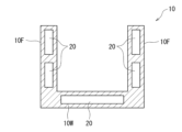
- the C-shaped column body 10 includes a web 10W and a pair of flanges 10F, 10F extending vertically from both ends of the web 10W, and has a C-shaped cross section as a whole. have.
- a hollow portion 20 (a plurality of long holes) is provided in at least one of the three portions of the web 10W and the pair of flanges 10F. As shown in FIG. 24A, all three portions may be provided, or as shown in FIG. 24B, only the web 10W may be provided.
- the number of long holes provided in each of the three portions is not particularly limited. In the case of meandering type as in the first embodiment, the total number of elongated holes should be an odd number of 3 or more. good.
- the H-shaped column body 10 includes a web 10W and a pair of flanges 10F extending vertically from both ends of the web 10W, and has an H-shaped cross section as a whole.
- the hollow portion 20 is provided and the number of long holes forming the hollow portion 20 are the same as those of the C-shaped column body 10 described above.
- the elongated holes may be arranged in the thickness direction of the web 10W.
Landscapes
- Engineering & Computer Science (AREA)
- Life Sciences & Earth Sciences (AREA)
- Physics & Mathematics (AREA)
- Sustainable Energy (AREA)
- Sustainable Development (AREA)
- Combustion & Propulsion (AREA)
- Thermal Sciences (AREA)
- Chemical & Material Sciences (AREA)
- Mechanical Engineering (AREA)
- General Engineering & Computer Science (AREA)
- Architecture (AREA)
- Environmental Sciences (AREA)
- Soil Sciences (AREA)
- Structural Engineering (AREA)
- Civil Engineering (AREA)
- Electromagnetism (AREA)
- Acoustics & Sound (AREA)
- Greenhouses (AREA)
Abstract
Description
図1を参照すると、本実施形態における農業ハウス(建造物)1は、地面2に対して設置領域が長方形となるように設置された建物で、柱材(構造部材)80A,80B、梁材(構造部材)81、一対の合掌梁材(構造部材)82A,82B、及びそれらを覆う透光性ビニルシートやガラス板(図示せず)を備える。
図12を参照すると、第2実施形態に係る農業ハウス1の構成は、以下の点で第1実施形態と異なる。第2実施形態のその他の構成は第1実施形態と同様であり、第1実施形態と同一ないし同様の要素には同一の符号を付している。
図13を参照すると、第3実施形態に係る農業ハウス1の構成は、以下の点で第1実施形態と異なる。第3実施形態のその他の構成は第1実施形態と同様であり、第1実施形態と同一ないし同様の要素には同一の符号を付している。
図14を参照すると、第4実施形態に係る農業ハウス1の構成は、以下の点で第1実施形態と異なる。第4実施形態のその他の構成は第1実施形態と同様であり、第1実施形態と同一ないし同様の要素には同一の符号を付している。
図15及び図16を参照すると、第5実施形態に係る農業ハウス1の構成は、以下の点で第1実施形態と異なる。第5実施形態のその他の構成は第1実施形態と同様であり、第1実施形態と同一ないし同様の要素には同一の符号を付している。
図17~図22を参照すると、第6実施形態に係る農業ハウス1の構成は、以下の点で第1実施形態と異なる。第6実施形態のその他の構成は第1実施形態と同様であり、第1実施形態と同一ないし同様の要素には同一の符号を付している。
図23を参照すると、第7実施形態に係る農業ハウス1の構成は、以下の点で第1実施形態と異なる。第7実施形態のその他の構成は第1実施形態と同様であり、第1実施形態と同一ないし同様の要素には同一の符号を付している。
上記実施形態では、構造部材本体が、矩形状の断面を有していたが、構造部材本体の断面形状は特に限定されない。図24Aおよび図24Bに示すように、柱材本体10は、C状またはU状の断面を有していてもよい。図25Aおよび図25Bに示すように、柱材本体10は、H状の断面を有していてもよい。素材はアルミニウム合金に限定されず、他の金属材料、例えば鉄鋼、アルミニウム、銅、銅合金、又は銀等でもよい。その他の構造部材(例えば、梁材および合掌梁材)の本体もこれと同様に変更可能である。
2 地面
4 地中
10 柱材本体(構造部材本体)
10a 面(受光面)
10b,10c,10d 面
11 空洞
12A,12B 埋設部
15 第1端部
16 第2端部
17A,17C 第1流路
17B 第2流路
18A,18B,18C 第1開口
19A,19B,19C 第2開口
20 中空部
21A,21B 隔壁
22A,22B 通液孔
30 リブ
36 黒色の皮膜
37A,37B,37C 断熱材
40A,40B 蓋部
41A,41B 窪部
42 流入口
43 流出口
44A,44B 基礎部
45A,45B 接続流路
46A,46B 流入出流路
47a 頂面
47b 底面
47c,47d,47e,47f 側面
48a 頂面
48b 底面
48c,48d,48e,48f 側面
49A,49B 開口
50A,50B 当接面
51A,51B,51C,51D 開口
52A,52B,52C,52D 開口
58 タンク
59 ポンプ
60 制御部
61 放熱器
62 三方弁
63a,63b,63c 外部配管
64 栽培空間
65 上部空間
66a,66b,66c,66d,66e,66f 配管
80A,80B 柱材(構造部材)
81 梁材(構造部材)
82A,82B 合掌梁材(構造部材)
83 連結部材
90 接続蓋部
91 蓋部流路
92 ねじ
Claims (14)
- 少なくとも一つの構造部材を備え、
前記構造部材は、
金属の押出成形ないし鋳造により成形され、太陽光が照射される受光面を備え、第1端部から第2端部に向かって延在する中空部が内部に形成された構造部材本体と、
前記第1端部と前記第2端部とにそれぞれ配置され、前記中空部を塞ぐ一対の蓋部と、
前記一対の蓋部のいずれかに設けられ、熱媒が前記中空部に流入する流入口と、
前記一対の蓋部のいずれかに設けられ、前記熱媒が前記中空部から流出する流出口と
を備える、建造物。 - 前記中空部は、
前記第1端部から前記第2端部に向かって前記熱媒が流れる第1流路と、
前記第1流路に隔壁を介して隣り合うように配置され、前記第2端部から前記第1端部に向かって前記熱媒が流れる第2流路と
を備える、請求項1に記載の建造物。 - 前記一対の蓋部のそれぞれには、前記熱媒が前記流入口から前記流出口に向かって蛇行して流れるように、前記第1流路と前記第2流路とを接続する接続流路が設けられている、
請求項2に記載の建造物。 - 前記構造部材本体は、前記隔壁に設けられ、前記熱媒が前記流入口から前記流出口に向かって蛇行して流れるように、前記第1流路と前記第2流路とを接続する通液孔を有する、
請求項2に記載の建造物。 - 前記中空部は、隔壁を介して互いに隣り合うように配置され、前記第1端部から前記第2端部に向かって前記熱媒が流れる複数の第1流路を備える、
請求項1に記載の建造物。 - 前記一対の蓋部のそれぞれには、前記熱媒が前記流入口から前記複数の第1流路へと分流し、前記複数の第1流路から合流して前記流出口に向かって流れるように、前記複数の第1流路の開口端それぞれと連通する共通流路が設けられている、
請求項5に記載の建造物。 - 前記構造部材本体は、前記第1端部および前記第2端部に設けられ、前記複数の第1流路の端部同士を連通させる凹部を有し、前記一対の蓋部のそれぞれには、前記流入口または前記流出口を前記凹部と連通させる流入出流路が設けられている、
請求項5に記載の建造物。 - 前記構造部材本体には、前記中空部が延在する方向に沿ってリブが設けられている、請求項1から7のいずれか1項に記載の建造物。
- 前記受光面には黒色の皮膜が被膜されている、請求項1から8のいずれか1項に記載の建造物。
- 前記構造部材本体の前記受光面を除く外面に断熱材が配置されている、請求項1から9のいずれか1項に記載の建造物。
- 前記構造部材は、地面に固定され縦方向に延びる柱材である、請求項1から10のいずれか1項に記載の建造物。
- 前記構造部材は、前記地面を超えて延長され、地中に埋設される埋設部を備える、請求項11に記載の建造物。
- 前記構造部材は、横方向に延びる梁材である、請求項1から12のいずれか1項に記載の建造物。
- 前記構造部材は、斜め方向に延び、互いに接続されている一対の合掌梁材である、請求項1から13のいずれか1項に記載の建造物。
Priority Applications (3)
| Application Number | Priority Date | Filing Date | Title |
|---|---|---|---|
| CN202280054891.1A CN117794356A (zh) | 2021-08-17 | 2022-06-09 | 建筑物 |
| EP22858140.1A EP4345223A4 (en) | 2021-08-17 | 2022-06-09 | BUILDING |
| US18/683,466 US20240349659A1 (en) | 2021-08-17 | 2022-06-09 | Building |
Applications Claiming Priority (4)
| Application Number | Priority Date | Filing Date | Title |
|---|---|---|---|
| JP2021132884 | 2021-08-17 | ||
| JP2021-132884 | 2021-08-17 | ||
| JP2022048867A JP7763694B2 (ja) | 2021-08-17 | 2022-03-24 | 建造物 |
| JP2022-048867 | 2022-03-24 |
Publications (1)
| Publication Number | Publication Date |
|---|---|
| WO2023021816A1 true WO2023021816A1 (ja) | 2023-02-23 |
Family
ID=85240434
Family Applications (1)
| Application Number | Title | Priority Date | Filing Date |
|---|---|---|---|
| PCT/JP2022/023328 Ceased WO2023021816A1 (ja) | 2021-08-17 | 2022-06-09 | 建造物 |
Country Status (3)
| Country | Link |
|---|---|
| US (1) | US20240349659A1 (ja) |
| EP (1) | EP4345223A4 (ja) |
| WO (1) | WO2023021816A1 (ja) |
Citations (10)
| Publication number | Priority date | Publication date | Assignee | Title |
|---|---|---|---|---|
| JPS50117054U (ja) * | 1974-03-07 | 1975-09-23 | ||
| JPS553519A (en) * | 1978-06-21 | 1980-01-11 | Hideaki Shibata | Light transmission building material for collecting solar heat |
| JPS5857652U (ja) * | 1981-10-15 | 1983-04-19 | 株式会社ブリヂストン | 可撓性熱交換用マツト |
| JPH10253169A (ja) * | 1997-03-14 | 1998-09-25 | Tokyo Gas Co Ltd | 水道直結型ソーラーシステム |
| WO2009044623A1 (ja) * | 2007-10-01 | 2009-04-09 | Mitaka Kohki Co., Ltd. | 太陽熱利用システム及びそれを用いた植物栽培、家畜飼育方法 |
| JP2011010624A (ja) * | 2009-07-03 | 2011-01-20 | Daiwa House Industry Co Ltd | ハウス栽培用の暖房システム |
| JP2012242016A (ja) * | 2011-05-20 | 2012-12-10 | Nishiyama Corp | 外壁面設置用太陽熱集熱器、建築物および太陽熱利用システム |
| JP3203197U (ja) * | 2016-01-04 | 2016-03-17 | 上山 博明 | 簡易型ハウス |
| US20160138831A1 (en) * | 2014-11-13 | 2016-05-19 | Hsiu-Lin Peng | Solar thermal collector and building accessory structure |
| JP2019122271A (ja) | 2018-01-12 | 2019-07-25 | 日鉄建材株式会社 | 農業用ハウス |
Family Cites Families (18)
| Publication number | Priority date | Publication date | Assignee | Title |
|---|---|---|---|---|
| DE1509678A1 (de) * | 1965-05-28 | 1969-02-27 | Menzel Heinrich | Abschirmvorrichtung,z.B. fuer Gewaechshaeuser |
| US4098262A (en) * | 1975-09-26 | 1978-07-04 | Walter Todd Peters | Heating apparatus using solar energy |
| US4295415A (en) * | 1979-08-16 | 1981-10-20 | Schneider Peter J Jr | Environmentally heated and cooled pre-fabricated insulated concrete building |
| US4498526A (en) * | 1981-11-09 | 1985-02-12 | Arenas Frank B | Solar efficient structure |
| US4611576A (en) * | 1982-08-19 | 1986-09-16 | Stephens Ceacer O | Solar energy collector |
| US4509502A (en) * | 1982-11-15 | 1985-04-09 | Jack Youcha | Multiple lens cover for solar heating panel |
| US4529123A (en) * | 1983-09-02 | 1985-07-16 | Combustion Research Corporation | Radiant heater system |
| US4519383A (en) * | 1984-03-30 | 1985-05-28 | Larkin William J | Anti-reverse siphon solar heating system |
| JPS611953A (ja) * | 1984-06-13 | 1986-01-07 | Shinichi Kawashima | 太陽熱暖房温室 |
| US5259363A (en) * | 1991-12-23 | 1993-11-09 | Lolar Logistics, Inc. | Solar roofing system |
| WO2003085329A1 (en) * | 2002-04-10 | 2003-10-16 | Neil Christopher Hellmann | A solar panel structure |
| US6837236B1 (en) * | 2002-08-21 | 2005-01-04 | Michael Lichtenberger | Solar energy conversion system |
| AU2006257804A1 (en) * | 2005-06-13 | 2006-12-21 | Helmut Karl Nass | Solar thermal collector |
| WO2010044789A1 (en) * | 2008-10-15 | 2010-04-22 | Swift, John | Building-integrated solar thermal micro-channel absorber and method of manufacturing thereof |
| SE537835C2 (sv) * | 2014-02-14 | 2015-11-03 | Kristianstads Industriservice Ab | Solfångare |
| US12044416B2 (en) * | 2017-02-17 | 2024-07-23 | Ceres Greenhouse Solutions Llc | Energy efficient enclosure temperature regulation system |
| EP3587959B1 (en) * | 2017-02-27 | 2022-09-21 | Porta-Park, Inc. | Heat exchanging device |
| EP4345398A4 (en) * | 2021-08-17 | 2024-10-02 | Kabushiki Kaisha Kobe Seiko Sho (Kobe Steel, Ltd.) | HEAT RECOVERY ELEMENT AND AGRICULTURAL HOUSE |
-
2022
- 2022-06-09 WO PCT/JP2022/023328 patent/WO2023021816A1/ja not_active Ceased
- 2022-06-09 US US18/683,466 patent/US20240349659A1/en active Pending
- 2022-06-09 EP EP22858140.1A patent/EP4345223A4/en active Pending
Patent Citations (10)
| Publication number | Priority date | Publication date | Assignee | Title |
|---|---|---|---|---|
| JPS50117054U (ja) * | 1974-03-07 | 1975-09-23 | ||
| JPS553519A (en) * | 1978-06-21 | 1980-01-11 | Hideaki Shibata | Light transmission building material for collecting solar heat |
| JPS5857652U (ja) * | 1981-10-15 | 1983-04-19 | 株式会社ブリヂストン | 可撓性熱交換用マツト |
| JPH10253169A (ja) * | 1997-03-14 | 1998-09-25 | Tokyo Gas Co Ltd | 水道直結型ソーラーシステム |
| WO2009044623A1 (ja) * | 2007-10-01 | 2009-04-09 | Mitaka Kohki Co., Ltd. | 太陽熱利用システム及びそれを用いた植物栽培、家畜飼育方法 |
| JP2011010624A (ja) * | 2009-07-03 | 2011-01-20 | Daiwa House Industry Co Ltd | ハウス栽培用の暖房システム |
| JP2012242016A (ja) * | 2011-05-20 | 2012-12-10 | Nishiyama Corp | 外壁面設置用太陽熱集熱器、建築物および太陽熱利用システム |
| US20160138831A1 (en) * | 2014-11-13 | 2016-05-19 | Hsiu-Lin Peng | Solar thermal collector and building accessory structure |
| JP3203197U (ja) * | 2016-01-04 | 2016-03-17 | 上山 博明 | 簡易型ハウス |
| JP2019122271A (ja) | 2018-01-12 | 2019-07-25 | 日鉄建材株式会社 | 農業用ハウス |
Non-Patent Citations (1)
| Title |
|---|
| See also references of EP4345223A4 |
Also Published As
| Publication number | Publication date |
|---|---|
| US20240349659A1 (en) | 2024-10-24 |
| EP4345223A4 (en) | 2024-10-09 |
| EP4345223A1 (en) | 2024-04-03 |
Similar Documents
| Publication | Publication Date | Title |
|---|---|---|
| Davies et al. | The seawater greenhouse in the United Arab Emirates: Thermal modelling and evaluation of design options | |
| JP7763694B2 (ja) | 建造物 | |
| US4462390A (en) | Modular solar greenhouse with elevated overhead heat storage material and movable insulation barriers and method and system for solar heating of attached living space using thermostat-controlled air circulation for harvesting heat | |
| US9091462B2 (en) | Solar canopy systems and methods | |
| JP7572583B2 (ja) | 農業ハウス | |
| US20120145223A1 (en) | Solar thermal energy collector | |
| US4314544A (en) | Solar collector for a window frame | |
| EP4345223A1 (en) | Building | |
| RU2706495C1 (ru) | Пространственная железобетонная фундаментная платформа на вечномерзлом грунте | |
| CN104737853A (zh) | 一种果树专用不对称拱轨日光温室系统及其建造方法 | |
| CN117794356A (zh) | 建筑物 | |
| US20110283994A1 (en) | Solar collector (embodiments) and a method for producing a solar collector enclosure | |
| ES2983736T3 (es) | Estructura modular para la construcción de edificaciones | |
| CN204907337U (zh) | 一种果树专用不对称拱轨日光温室系统 | |
| JP2026014674A (ja) | 構造体 | |
| CN117597557A (zh) | 集热构件以及农业大棚 | |
| US20080121226A1 (en) | Cementitious Solar Trough | |
| JP2023027745A (ja) | 集熱部材および農業ハウス | |
| RO123624B1 (ro) | Radiator la un rând sau cu rânduri multiple, cu cel puţin două secţiuni | |
| Nisbet et al. | The application of the transwall to horticultural glasshouses | |
| CN116927346B (zh) | 一种超低能耗模块化建筑房屋体系 | |
| KR102535238B1 (ko) | 비닐하우스 및 이의 제조방법 | |
| WO2019239740A1 (ja) | 太陽光パネル用架台 | |
| KR20250075903A (ko) | 프리패브 방식의 건물 일체형 태양광 발전 지붕 시스템 | |
| JP2019080528A (ja) | 補強農業用パイプビニールハウス及び補強農業用パイプビニールハウスの製造方法 |
Legal Events
| Date | Code | Title | Description |
|---|---|---|---|
| 121 | Ep: the epo has been informed by wipo that ep was designated in this application |
Ref document number: 22858140 Country of ref document: EP Kind code of ref document: A1 |
|
| WWE | Wipo information: entry into national phase |
Ref document number: 2022858140 Country of ref document: EP |
|
| WWE | Wipo information: entry into national phase |
Ref document number: 202280054891.1 Country of ref document: CN |
|
| ENP | Entry into the national phase |
Ref document number: 2022858140 Country of ref document: EP Effective date: 20231229 |
|
| WWE | Wipo information: entry into national phase |
Ref document number: 18683466 Country of ref document: US |
|
| NENP | Non-entry into the national phase |
Ref country code: DE |