WO2023021861A1 - 負極及び負極の製造方法 - Google Patents
負極及び負極の製造方法 Download PDFInfo
- Publication number
- WO2023021861A1 WO2023021861A1 PCT/JP2022/026347 JP2022026347W WO2023021861A1 WO 2023021861 A1 WO2023021861 A1 WO 2023021861A1 JP 2022026347 W JP2022026347 W JP 2022026347W WO 2023021861 A1 WO2023021861 A1 WO 2023021861A1
- Authority
- WO
- WIPO (PCT)
- Prior art keywords
- negative electrode
- active material
- electrode active
- silicon
- layer
- Prior art date
- Legal status (The legal status is an assumption and is not a legal conclusion. Google has not performed a legal analysis and makes no representation as to the accuracy of the status listed.)
- Ceased
Links
Images


Classifications
-
- H—ELECTRICITY
- H01—ELECTRIC ELEMENTS
- H01M—PROCESSES OR MEANS, e.g. BATTERIES, FOR THE DIRECT CONVERSION OF CHEMICAL ENERGY INTO ELECTRICAL ENERGY
- H01M4/00—Electrodes
- H01M4/02—Electrodes composed of, or comprising, active material
- H01M4/36—Selection of substances as active materials, active masses, active liquids
- H01M4/362—Composites
- H01M4/366—Composites as layered products
-
- H—ELECTRICITY
- H01—ELECTRIC ELEMENTS
- H01M—PROCESSES OR MEANS, e.g. BATTERIES, FOR THE DIRECT CONVERSION OF CHEMICAL ENERGY INTO ELECTRICAL ENERGY
- H01M4/00—Electrodes
- H01M4/02—Electrodes composed of, or comprising, active material
- H01M4/13—Electrodes for accumulators with non-aqueous electrolyte, e.g. for lithium-accumulators; Processes of manufacture thereof
-
- H—ELECTRICITY
- H01—ELECTRIC ELEMENTS
- H01M—PROCESSES OR MEANS, e.g. BATTERIES, FOR THE DIRECT CONVERSION OF CHEMICAL ENERGY INTO ELECTRICAL ENERGY
- H01M10/00—Secondary cells; Manufacture thereof
- H01M10/04—Construction or manufacture in general
- H01M10/0404—Machines for assembling batteries
- H01M10/0409—Machines for assembling batteries for cells with wound electrodes
-
- H—ELECTRICITY
- H01—ELECTRIC ELEMENTS
- H01M—PROCESSES OR MEANS, e.g. BATTERIES, FOR THE DIRECT CONVERSION OF CHEMICAL ENERGY INTO ELECTRICAL ENERGY
- H01M10/00—Secondary cells; Manufacture thereof
- H01M10/05—Accumulators with non-aqueous electrolyte
- H01M10/052—Li-accumulators
- H01M10/0525—Rocking-chair batteries, i.e. batteries with lithium insertion or intercalation in both electrodes; Lithium-ion batteries
-
- H—ELECTRICITY
- H01—ELECTRIC ELEMENTS
- H01M—PROCESSES OR MEANS, e.g. BATTERIES, FOR THE DIRECT CONVERSION OF CHEMICAL ENERGY INTO ELECTRICAL ENERGY
- H01M4/00—Electrodes
- H01M4/02—Electrodes composed of, or comprising, active material
- H01M4/04—Processes of manufacture in general
-
- H—ELECTRICITY
- H01—ELECTRIC ELEMENTS
- H01M—PROCESSES OR MEANS, e.g. BATTERIES, FOR THE DIRECT CONVERSION OF CHEMICAL ENERGY INTO ELECTRICAL ENERGY
- H01M4/00—Electrodes
- H01M4/02—Electrodes composed of, or comprising, active material
- H01M4/04—Processes of manufacture in general
- H01M4/0402—Methods of deposition of the material
- H01M4/0421—Methods of deposition of the material involving vapour deposition
-
- H—ELECTRICITY
- H01—ELECTRIC ELEMENTS
- H01M—PROCESSES OR MEANS, e.g. BATTERIES, FOR THE DIRECT CONVERSION OF CHEMICAL ENERGY INTO ELECTRICAL ENERGY
- H01M4/00—Electrodes
- H01M4/02—Electrodes composed of, or comprising, active material
- H01M4/04—Processes of manufacture in general
- H01M4/049—Manufacturing of an active layer by chemical means
- H01M4/0492—Chemical attack of the support material
-
- H—ELECTRICITY
- H01—ELECTRIC ELEMENTS
- H01M—PROCESSES OR MEANS, e.g. BATTERIES, FOR THE DIRECT CONVERSION OF CHEMICAL ENERGY INTO ELECTRICAL ENERGY
- H01M4/00—Electrodes
- H01M4/02—Electrodes composed of, or comprising, active material
- H01M4/13—Electrodes for accumulators with non-aqueous electrolyte, e.g. for lithium-accumulators; Processes of manufacture thereof
- H01M4/131—Electrodes based on mixed oxides or hydroxides, or on mixtures of oxides or hydroxides, e.g. LiCoOx
-
- H—ELECTRICITY
- H01—ELECTRIC ELEMENTS
- H01M—PROCESSES OR MEANS, e.g. BATTERIES, FOR THE DIRECT CONVERSION OF CHEMICAL ENERGY INTO ELECTRICAL ENERGY
- H01M4/00—Electrodes
- H01M4/02—Electrodes composed of, or comprising, active material
- H01M4/13—Electrodes for accumulators with non-aqueous electrolyte, e.g. for lithium-accumulators; Processes of manufacture thereof
- H01M4/134—Electrodes based on metals, Si or alloys
-
- H—ELECTRICITY
- H01—ELECTRIC ELEMENTS
- H01M—PROCESSES OR MEANS, e.g. BATTERIES, FOR THE DIRECT CONVERSION OF CHEMICAL ENERGY INTO ELECTRICAL ENERGY
- H01M4/00—Electrodes
- H01M4/02—Electrodes composed of, or comprising, active material
- H01M4/13—Electrodes for accumulators with non-aqueous electrolyte, e.g. for lithium-accumulators; Processes of manufacture thereof
- H01M4/136—Electrodes based on inorganic compounds other than oxides or hydroxides, e.g. sulfides, selenides, tellurides, halogenides or LiCoFy
-
- H—ELECTRICITY
- H01—ELECTRIC ELEMENTS
- H01M—PROCESSES OR MEANS, e.g. BATTERIES, FOR THE DIRECT CONVERSION OF CHEMICAL ENERGY INTO ELECTRICAL ENERGY
- H01M4/00—Electrodes
- H01M4/02—Electrodes composed of, or comprising, active material
- H01M4/13—Electrodes for accumulators with non-aqueous electrolyte, e.g. for lithium-accumulators; Processes of manufacture thereof
- H01M4/139—Processes of manufacture
- H01M4/1391—Processes of manufacture of electrodes based on mixed oxides or hydroxides, or on mixtures of oxides or hydroxides, e.g. LiCoOx
-
- H—ELECTRICITY
- H01—ELECTRIC ELEMENTS
- H01M—PROCESSES OR MEANS, e.g. BATTERIES, FOR THE DIRECT CONVERSION OF CHEMICAL ENERGY INTO ELECTRICAL ENERGY
- H01M4/00—Electrodes
- H01M4/02—Electrodes composed of, or comprising, active material
- H01M4/13—Electrodes for accumulators with non-aqueous electrolyte, e.g. for lithium-accumulators; Processes of manufacture thereof
- H01M4/139—Processes of manufacture
- H01M4/1395—Processes of manufacture of electrodes based on metals, Si or alloys
-
- H—ELECTRICITY
- H01—ELECTRIC ELEMENTS
- H01M—PROCESSES OR MEANS, e.g. BATTERIES, FOR THE DIRECT CONVERSION OF CHEMICAL ENERGY INTO ELECTRICAL ENERGY
- H01M4/00—Electrodes
- H01M4/02—Electrodes composed of, or comprising, active material
- H01M4/36—Selection of substances as active materials, active masses, active liquids
- H01M4/48—Selection of substances as active materials, active masses, active liquids of inorganic oxides or hydroxides
- H01M4/483—Selection of substances as active materials, active masses, active liquids of inorganic oxides or hydroxides for non-aqueous cells
-
- H—ELECTRICITY
- H01—ELECTRIC ELEMENTS
- H01M—PROCESSES OR MEANS, e.g. BATTERIES, FOR THE DIRECT CONVERSION OF CHEMICAL ENERGY INTO ELECTRICAL ENERGY
- H01M4/00—Electrodes
- H01M4/02—Electrodes composed of, or comprising, active material
- H01M4/36—Selection of substances as active materials, active masses, active liquids
- H01M4/58—Selection of substances as active materials, active masses, active liquids of inorganic compounds other than oxides or hydroxides, e.g. sulfides, selenides, tellurides, halogenides or LiCoFy; of polyanionic structures, e.g. phosphates, silicates or borates
- H01M4/5825—Oxygenated metallic salts or polyanionic structures, e.g. borates, phosphates, silicates, olivines
-
- H—ELECTRICITY
- H01—ELECTRIC ELEMENTS
- H01M—PROCESSES OR MEANS, e.g. BATTERIES, FOR THE DIRECT CONVERSION OF CHEMICAL ENERGY INTO ELECTRICAL ENERGY
- H01M4/00—Electrodes
- H01M4/02—Electrodes composed of, or comprising, active material
- H01M4/64—Carriers or collectors
- H01M4/66—Selection of materials
-
- H—ELECTRICITY
- H01—ELECTRIC ELEMENTS
- H01M—PROCESSES OR MEANS, e.g. BATTERIES, FOR THE DIRECT CONVERSION OF CHEMICAL ENERGY INTO ELECTRICAL ENERGY
- H01M4/00—Electrodes
- H01M4/02—Electrodes composed of, or comprising, active material
- H01M4/64—Carriers or collectors
- H01M4/70—Carriers or collectors characterised by shape or form
-
- H—ELECTRICITY
- H01—ELECTRIC ELEMENTS
- H01M—PROCESSES OR MEANS, e.g. BATTERIES, FOR THE DIRECT CONVERSION OF CHEMICAL ENERGY INTO ELECTRICAL ENERGY
- H01M4/00—Electrodes
- H01M4/02—Electrodes composed of, or comprising, active material
- H01M2004/021—Physical characteristics, e.g. porosity, surface area
-
- H—ELECTRICITY
- H01—ELECTRIC ELEMENTS
- H01M—PROCESSES OR MEANS, e.g. BATTERIES, FOR THE DIRECT CONVERSION OF CHEMICAL ENERGY INTO ELECTRICAL ENERGY
- H01M4/00—Electrodes
- H01M4/02—Electrodes composed of, or comprising, active material
- H01M2004/026—Electrodes composed of, or comprising, active material characterised by the polarity
- H01M2004/027—Negative electrodes
-
- Y—GENERAL TAGGING OF NEW TECHNOLOGICAL DEVELOPMENTS; GENERAL TAGGING OF CROSS-SECTIONAL TECHNOLOGIES SPANNING OVER SEVERAL SECTIONS OF THE IPC; TECHNICAL SUBJECTS COVERED BY FORMER USPC CROSS-REFERENCE ART COLLECTIONS [XRACs] AND DIGESTS
- Y02—TECHNOLOGIES OR APPLICATIONS FOR MITIGATION OR ADAPTATION AGAINST CLIMATE CHANGE
- Y02E—REDUCTION OF GREENHOUSE GAS [GHG] EMISSIONS, RELATED TO ENERGY GENERATION, TRANSMISSION OR DISTRIBUTION
- Y02E60/00—Enabling technologies; Technologies with a potential or indirect contribution to GHG emissions mitigation
- Y02E60/10—Energy storage using batteries
Definitions
- the present invention relates to a negative electrode and a method for manufacturing a negative electrode.
- lithium-ion secondary batteries are highly expected because they are easy to make smaller and have higher capacity, and they can obtain higher energy density than lead-acid batteries and nickel-cadmium batteries.
- the lithium-ion secondary battery described above includes a positive electrode, a negative electrode, a separator, and an electrolytic solution, and the negative electrode contains a negative electrode active material involved in charge-discharge reactions.
- the negative electrode active material expands and contracts during charging and discharging, so cracking occurs mainly near the surface layer of the negative electrode active material.
- an ionic substance is generated inside the active material, making the negative electrode active material fragile.
- a new surface is generated thereby increasing the reaction area of the active material.
- a decomposition reaction of the electrolytic solution occurs on the new surface, and a film, which is a decomposition product of the electrolytic solution, is formed on the new surface, so that the electrolytic solution is consumed.
- cycle characteristics tend to deteriorate.
- silicon and amorphous silicon dioxide are simultaneously deposited using a vapor phase method (see Patent Document 1, for example).
- a carbon material electroconductive material
- an active material containing silicon and oxygen is produced, and an active material layer with a high oxygen ratio is formed in the vicinity of the current collector ( For example, see Patent Document 3).
- oxygen is contained in the silicon active material, and the average oxygen content is 40 at % or less, and the oxygen content is increased near the current collector. (See Patent Document 4, for example).
- a nanocomposite containing a Si phase, SiO 2 and MyO metal oxide is used to improve the initial charge/discharge efficiency (see Patent Document 5, for example).
- a carbon material are mixed and sintered at a high temperature (see Patent Document 6, for example).
- the molar ratio of oxygen to silicon in the negative electrode active material is set to 0.1 to 1.2, and the difference between the maximum and minimum molar ratios near the interface between the active material and the current collector is 0.4 or less (see Patent Document 7, for example).
- a metal oxide containing lithium is used (see, for example, Patent Document 8).
- a hydrophobic layer such as a silane compound is formed on the surface layer of the silicon material (see, for example, Patent Document 9).
- silicon oxide is used, and conductivity is imparted by forming a graphite film on the surface layer (see, for example, Patent Document 10).
- broad peaks appear at 1330 cm ⁇ 1 and 1580 cm ⁇ 1 with respect to the shift values obtained from the RAMAN spectrum of the graphite film, and their intensity ratio I 1330 /I 1580 is 1.5 ⁇ I 1330 /I 1580 ⁇ 3.
- particles having a silicon microcrystalline phase dispersed in silicon dioxide are used in order to increase battery capacity and improve cycle characteristics (see, for example, Patent Document 11).
- a silicon oxide in which the atomic ratio of silicon and oxygen is controlled to 1:y (0 ⁇ y ⁇ 2) is used (see Patent Document 12, for example).
- Non-Patent Document 1 Hitachi Maxell began shipments of prismatic secondary batteries for smartphones that adopted nanosilicon composites in June 2010 (see, for example, Non-Patent Document 1). .
- the silicon oxide proposed by Hohl is a composite of Si 0+ to Si 4+ and has various oxidation states (see Non-Patent Document 2).
- Kapaklis also proposed a disproportionated structure in which silicon oxide is divided into Si and SiO 2 by applying a thermal load (see Non-Patent Document 3).
- Miyachi et al. focused on Si and SiO2 that contribute to charging and discharging (see Non-Patent Document 4), and Yamada et al. (See Non-Patent Document 5).
- the above reaction formula indicates that Si and SiO 2 that constitute silicon oxide react with Li and separate into Li silicide, Li silicate, and partly unreacted SiO 2 .
- the Li silicate produced here is irreversible, and is said to be a stable substance that does not release Li once formed.
- the capacity per mass calculated from this reaction formula has a value close to the experimental value, and is recognized as a reaction mechanism of silicon oxide.
- Kim et al. identified Li silicate, an irreversible component associated with charging and discharging of silicon oxide, as Li 4 SiO 4 using 7 Li-MAS-NMR and 29 Si-MAS-NMR (see Non-Patent Document 6). ).
- lithium-ion secondary batteries which are the main power source for these devices, have been required to have increased battery capacity.
- the development of a lithium ion secondary battery comprising a negative electrode using a silicon material as a main material is desired.
- lithium ion secondary batteries using a silicon material are desired to have initial charge/discharge characteristics and cycle characteristics that are close to those of lithium ion secondary batteries using a carbon-based active material. Therefore, the cycle characteristics and the initial charge/discharge characteristics have been improved by using silicon oxides modified by the insertion and partial elimination of Li as the negative electrode active material.
- Non-Patent Document 8 Li—SiO—C (Non-Patent Document 8) is used as the silicon oxide and 100% of the carbon anode material is replaced with a carbon anode material to make a trial battery, this battery is still superior to the battery using the carbon anode material. , the capacity increase remains in the high 20% range. This means that further improvement in battery capacity is required when considering the improvement of performance of small electronic devices (5G, etc.) and the improvement of mileage of electric vehicles.
- the present invention has been made in view of the above problems, and provides a negative electrode capable of significantly increasing the capacity while maintaining excellent battery characteristics, and a negative electrode manufacturing method capable of manufacturing such a negative electrode. for the purpose.
- a negative electrode current collector having a roughened surface
- a negative electrode having a negative electrode active material layer provided on the negative electrode current collector contains negative electrode active material particles containing a compound of lithium, silicon, and oxygen, and the ratio O/Si of the oxygen to the silicon constituting the negative electrode active material particles is 0.8 or more1. is in the range of 2 or less
- the negative electrode active material layer has a multilayer structure consisting of two or more layers, and each layer of the multilayer structure of the negative electrode active material layer has tetravalent silicon containing at least one of lithium and oxygen on the top.
- the negative electrode of the present invention has a negative electrode active material layer containing negative electrode active material particles containing a compound of lithium, silicon, and oxygen, the battery capacity can be improved.
- the negative electrode active material layer can be directly supported on the roughened surface of the negative electrode current collector without using a binder, a conductive agent, etc., and does not participate in charging and discharging in the electrode.
- the energy density of the electrodes can be greatly improved due to the reduced area and the reduced excess air gaps.
- the ratio O/Si of oxygen to silicon constituting the negative electrode active material particles is in the range of 0.8 or more and 1.2 or less, so that excellent battery characteristics can be maintained. .
- the negative electrode active material layer having a multilayer structure consisting of two or more layers can realize smooth insertion of Li while suppressing decomposition of the electrolytic solution.
- each layer of the multilayer structure of the negative electrode active material layer has a layer containing a tetravalent silicon compound containing at least one of lithium and oxygen on the top, and this layer acts as a relaxation layer. be able to. Since the non-aqueous electrolyte can enter into this portion, each layer can be Li-doped (Li-inserted), ion concentration is suppressed, and expansion occurs uniformly. Since Li detachment is also possible in each layer, shrinkage also occurs uniformly. As a result, expansion and contraction of the negative electrode due to charging and discharging can be alleviated, and a stable negative electrode active material layer can be maintained.
- the negative electrode of the present invention it is possible to significantly increase the capacity while maintaining excellent battery characteristics, particularly excellent cycle characteristics.
- the tetravalent silicon compound preferably contains one or more selected from SiO 2 and Li 4 SiO 4 .
- SiO 2 relaxes the expansion and contraction of the negative electrode , and Li 4 SiO 4 allows charging and discharging to proceed more smoothly. can.
- the negative electrode active material layer is the negative electrode active material particles; It is preferable to have a composite compound that is filled between the particles and in the surface layer of the negative electrode active material particles, in which at least carbon atoms and oxygen atoms are chemically bonded and that does not form an alloy with the negative electrode active material particles.
- This composite compound can serve as a protective layer that protects the interface between the negative electrode active material layer and the electrolyte. Due to the presence of such a composite compound, the negative electrode of the present invention can exhibit better cycle characteristics.
- the composite compound is a ring-opening decomposition product of a composite of an ether solvent and a polyphenylene compound or a polycyclic aromatic compound, or a ring-opening decomposition product of a composite in which the composite forms a complex with lithium.
- Such a composite compound can be easily formed in the process depending on the method of Li-doping the negative electrode active material particles.
- the negative electrode active material particles after charging and discharging at least 20 times have the largest amount of Si 1+ to Si 3+ silicon compound states.
- the negative electrode active material layer forms secondary particles that are aggregates of the primary particles after charging and discharging. It is preferred to have an inwardly separated configuration.
- the negative electrode active material particles have a peak due to the Si (111) crystal plane obtained by X-ray diffraction using Cu—K ⁇ rays before charging and discharging, and the crystallite size corresponding to the crystal plane is 1. 0 nm or less.
- the negative electrode current collector preferably has a surface with a ten-point average roughness Rz of 1.5 ⁇ m or more and 5.0 ⁇ m or less.
- a negative electrode containing such a negative electrode current collector can not only stably support the negative electrode active material layer, but also can provide an appropriate density of the negative electrode active material particles in the negative electrode active material layer. As a result, better battery characteristics can be exhibited.
- a method for manufacturing the negative electrode of the present invention comprising: winding the negative electrode current collector on a can roll having a curvature; a step of vapor-phase-growing a film containing silicon and/or silicon monoxide having a multi-layer structure consisting of two or more layers on the negative electrode current collector while running the negative electrode current collector on the can roll; A step of blowing an oxygen-containing gas onto the film containing silicon and/or silicon monoxide to form a multilayer structure layer containing silicon dioxide on top of each layer; and doping lithium into the layer of the multilayer structure to form the negative electrode active material layer.
- each layer of the multilayer structure containing the silicon oxide containing the silicon dioxide is formed,
- the silicon oxide is modified by an oxidation-reduction method to contain the lithium, silicon, and oxygen.
- the negative electrode of the present invention can significantly increase the capacity while maintaining excellent battery characteristics when used as the negative electrode of a secondary battery.
- the negative electrode of the present invention when used as a negative electrode of a secondary battery, it is possible to obtain high initial efficiency, high capacity, high input characteristics, and high cycle characteristics.
- the method for producing the negative electrode of the present invention it is possible to produce the negative electrode of the present invention that can significantly increase the capacity while maintaining excellent battery characteristics.
- the method for producing a negative electrode of the present invention it is possible to produce a negative electrode having good cycle characteristics and high capacity and good initial charge-discharge characteristics when used as a negative electrode of a secondary battery.
- FIG. 1 is a schematic cross-sectional view showing an example of the configuration of a negative electrode of the present invention
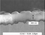
- FIG. 1 is a cross-sectional SEM image of an example of the negative electrode of the present invention
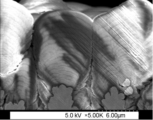
- 4 is a cross-sectional SEM image of another example of the negative electrode of the present invention.
- 1 is an exploded view showing a configuration example (laminate film type) of a lithium ion secondary battery including the negative electrode of the present invention.
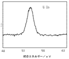
- FIG. 3 is part of the XPS spectrum of the surface layer of the negative electrode active material of Example 2.
- FIG. 3 is another part of the XPS spectrum of the negative electrode active material surface layer of Example 2.
- FIG. 4 is a surface SEM image of the negative electrode active material layer of Example 2 after charging and discharging.
- 3 is part of the XPS spectrum of the negative electrode active material layer of Example 2 after charging and discharging 20 times.
- Lithium ion secondary batteries using this silicon oxide are desired to have initial charge/discharge characteristics that are close to those of lithium ion secondary batteries using a carbonaceous active material. Also, by using Li-doped SiO, which can improve the initial charge/discharge characteristics, a significant increase in capacity can be expected.
- the present inventors have made intensive studies to obtain a negative electrode that can improve the initial charge-discharge characteristics and increase the battery capacity while obtaining high cycle characteristics when used as a negative electrode of a secondary battery. After repeating the above, the present invention was achieved.
- the present invention provides a negative electrode current collector having a roughened surface, A negative electrode having a negative electrode active material layer provided on the negative electrode current collector, The negative electrode active material layer contains negative electrode active material particles containing a compound of lithium, silicon, and oxygen, and the ratio O/Si of the oxygen to the silicon constituting the negative electrode active material particles is 0.8 or more1. is in the range of 2 or less,
- the negative electrode active material layer has a multilayer structure consisting of two or more layers, and each layer of the multilayer structure of the negative electrode active material layer has tetravalent silicon containing at least one of lithium and oxygen on the top.
- the present invention also provides a method for producing the negative electrode of the present invention, comprising: winding the negative electrode current collector on a can roll having a curvature; a step of vapor-phase-growing a film containing silicon and/or silicon monoxide having a multi-layer structure consisting of two or more layers on the negative electrode current collector while running the negative electrode current collector on the can roll; A step of blowing an oxygen-containing gas onto the film containing silicon and/or silicon monoxide to form a multilayer structure layer containing silicon dioxide on top of each layer; and doping lithium into the layer of the multilayer structure to form the negative electrode active material layer.
- FIG. 1 shows a schematic cross-sectional view of an example of the negative electrode of the present invention.
- the negative electrode 10 includes a negative electrode current collector 11 and a negative electrode active material layer 12 provided on a surface 11 a of the negative electrode current collector 11 .
- the negative electrode active material containing layer 12 may be provided on both surfaces 11a of the negative electrode current collector 11 as shown in FIG. 1, or may be provided only on one surface 11a.
- the surface 11a of the negative electrode current collector 11 is a roughened surface. That is, the negative electrode active material layer 12 is provided on the roughened surface 11 a of the negative electrode current collector 11 .
- the negative electrode current collector 11 and the negative electrode active material layer 12 will be described below.
- the negative electrode current collector 11 is made of an excellent conductive material and has high mechanical strength.
- Examples of conductive materials that can be used for the negative electrode current collector 11 include copper (Cu) and nickel (Ni). This conductive material is preferably a material that does not form an intermetallic compound with lithium (Li).
- the negative electrode current collector 11 preferably contains carbon (C) and sulfur (S) in addition to the main elements. This is because the physical strength of the negative electrode current collector is improved. This is because, in particular, in the case of having an active material layer that expands during charging, if the current collector contains the above element, it has the effect of suppressing deformation of the electrode including the current collector.
- the contents of the above-mentioned contained elements are not particularly limited, they are preferably 100 ppm by mass or less. This is because a higher deformation suppressing effect can be obtained. Cycle characteristics can be further improved by such a deformation suppression effect.
- the surface 11a of the negative electrode current collector 11 must be roughened, and desirably, the ten-point average roughness Rz of the surface is 1.5 ⁇ m or more and 5.0 ⁇ m or less.
- the negative electrode 10 including the negative electrode current collector 11 having the surface 11a with such a desirable average roughness Rz not only can the negative electrode active material layer 12 be supported more stably, but also the negative electrode active material layer 12 The density of the material particles can be made moderate, and as a result, better battery characteristics can be exhibited.
- the roughened negative electrode current collector 11 is, for example, a metal foil subjected to electrolytic treatment, embossing treatment, or chemical etching treatment.
- the negative electrode active material layer 12 of the negative electrode 10 of the present invention has negative electrode active material particles containing a compound of lithium, silicon, and oxygen, that is, silicon compound particles containing lithium and oxygen. is provided. It can be said that the negative electrode 10 has a structure in which negative electrode active material particles are directly supported on the roughened surface 11 a of the negative electrode current collector 11 .
- the negative electrode 10 of the present invention contains negative electrode active material particles that are silicon compound particles, the battery capacity can be improved.
- the negative electrode 10 of the present invention directly supports the negative electrode active material layer 12 on the roughened surface 11a of the negative electrode current collector 11 without using a binder, a conductive aid, or the like.
- the energy density of the electrode can be greatly improved because the area of the electrode that does not participate in charging and discharging can be reduced, and the excess voids can be reduced.
- the negative electrode 10 having the densely supported negative electrode active material layer 12 in this way, it is possible to increase the energy density of the battery, which cannot be achieved with, for example, a powder electrode.
- the ratio O/Si between oxygen and silicon constituting the negative electrode active material particles is in the range of 0.8 or more and 1.2 or less. If the ratio O/Si is 0.8 or more, the oxygen ratio is higher than that of simple silicon, so the cycle characteristics are good. A ratio O/Si of 1.2 or less is preferable because the resistance of the silicon oxide does not become too high.
- the composition of SiOx is preferably one in which x is close to 1. This is because high cycle characteristics can be obtained. Note that the composition of the silicon compound in the present invention does not necessarily mean 100% purity, and may contain trace amounts of impurity elements.
- the ratio O/Si is less than 0.8, the capacity increases, but the area where Si 0+ reacts with the electrolytic solution increases and the cycle characteristics deteriorate. Also, if the ratio O/Si exceeds 1.2, it becomes a load substance, and in this case also deteriorates the battery characteristics.
- the ratio O/Si is a molar ratio and should be as close to 1 as possible.
- the negative electrode active material layer 12 In order to introduce Li more smoothly, it is preferable to make the negative electrode active material layer 12 have a multi-layer structure consisting of two or more layers at the timing of forming the negative electrode active material layer 12 .
- the upper limit of the layers constituting the negative electrode active material layer 12 is not particularly limited.
- the negative electrode active material layer 12 can have a multi-layer structure consisting of 2 to 20 layers. This is because the negative electrode active material layer having a multilayer structure consisting of two or more layers can realize smooth insertion of Li while suppressing decomposition of the electrolytic solution. However, since it leads to an increase in the reaction area, the battery characteristics are insufficient as it is.
- each layer of the multilayer structure of the negative electrode active material layer 12 has a layer containing a tetravalent silicon compound containing at least one of lithium and oxygen in the upper portion. .
- this layer has not only the action of introducing and desorbing Li, but also the action of alleviating expansion and contraction during charging and discharging, so that the battery characteristics can be maintained.
- each layer can be Li-doped (Li-inserted), ion concentration is suppressed, and expansion occurs uniformly. Since Li detachment is also possible in each layer, shrinkage also occurs uniformly. As a result, expansion and contraction of the negative electrode due to charging and discharging can be alleviated, and a stable negative electrode active material layer can be maintained.
- the negative electrode 10 of the present invention it is possible to significantly increase the capacity while maintaining excellent battery characteristics, particularly excellent cycle characteristics.
- the tetravalent silicon compound preferably contains one or more selected from SiO 2 and Li 4 SiO 4 . This is because SiO 2 can further reduce the expansion and contraction of the negative electrode, and Li 4 SiO 4 can allow charging and discharging to proceed more smoothly.
- negative electrode active material particles having a compound of lithium, silicon, and oxygen can exist adjacent to each other. At least carbon atoms and oxygen atoms are chemically bonded between the particles and on the surface of the negative electrode active material particles, and a composite compound (“C, O It is preferably filled with a compound (also called "compound").
- This composite compound serves as a protective layer that protects the interface between the negative electrode active material layer and the electrolyte.
- the above composite compound that acts as a protective layer that suppresses the reaction with the electrolyte By filling the interparticle and surface layer of the negative electrode active material particles with the above composite compound that acts as a protective layer that suppresses the reaction with the electrolyte, the decomposition of the electrolyte is suppressed, Li is easily introduced, and the battery characteristics are maintained.
- the negative electrode active material layer 12 can be proposed. Due to the presence of such a complex compound, better cycle characteristics can be exhibited.
- the primary particles of the negative electrode active material particles have a multi-layered structure, and the interlayer portions thereof are similarly filled with the composite compound, thereby ensuring reactivity with the electrolytic solution. .
- the composite compound acting as a protective layer is a ring-opening decomposition product of a composite of an ether solvent and a polyphenylene compound or a polycyclic aromatic compound, or a ring-opening decomposition product of a composite in which the composite forms a complex with lithium.
- Such a composite compound can be easily formed in the process of Li-doping the negative electrode active material particles using an oxidation-reduction method.
- the composite compound in which at least carbon atoms and oxygen atoms are chemically bonded which can act as a protective layer, partially contains lithium. That is, the composite compound preferably contains lithium at least in part.
- the composite compound By compounding a composite oxide containing carbon and oxygen with lithium and containing lithium in a part of it, it behaves like a kind of solid electrolyte, and in particular, the permeation of Li is higher than when it contains only carbon and oxygen. Since it becomes possible to make it easy to occur and the diffusibility of Li can be improved, the battery characteristics can be further improved.
- Silicon monoxide which is represented by general silicon oxides, is often expressed as a compound of 0 to 4 valences of Si.
- Si2p spectrum of silicon monoxide is obtained by photoelectron spectroscopy, the peak of Si 0+ appears near the binding energy of 99 eV, and the peak of Si 4+ appears near the binding energy of 103 eV. It shows a spectrum in which the 0-valence state and the Si 4+ state are dominant.
- the negative electrode active material particles containing silicon are directly supported on the negative electrode current collector 11, the state of the roughened portion of the surface 11a of the negative electrode current collector 11, the temperature of the negative electrode current collector 11 (substrate on which vapor deposition is performed), and the negative electrode
- the structure of the silicon compound can be changed by controlling the traveling speed of the current collector 11, gas ejection, and the like.
- the negative electrode active material particles are repeatedly charged and discharged, for example, after charging and discharging at least 20 times, the particles have silicon in the Si 0+ state and silicon in the compound state of Si 1+ to Si 3+ .
- the compound state of Si 1+ to Si 3+ is most desirable.
- the upper limit of the number of times of charging and discharging in such a compound state is not particularly limited. It is desirable to have silicon in the 3+ compound state.
- the state of the valence of silicon in the negative electrode active material particles is determined by subjecting the photoelectron spectrum obtained by the photoelectron spectroscopy to a waveform separation process and confirming the presence or absence of a peak attributed to each valence state of silicon in the spectrum. , can be determined.
- the valence state of silicon in the negative electrode active material layer and the negative electrode active material particles contained therein can be confirmed, for example, by using a scanning X-ray photoelectron spectrometer PHI Quantera II manufactured by ULVAC-PHI. At this time, the X-ray beam diameter is 100 ⁇ m, and a neutralization gun can be used.
- the negative electrode active material particles grow in vapor phase from the roughened portion of the surface 11a of the negative electrode current collector 11 .
- these particles are defined as primary particles, it is preferable that secondary particles, which are aggregates of the primary particles, are formed after charging and discharging.
- Si 0+ constituting the negative electrode active material layer before charging and discharging is desirably non-crystalline (amorphous) as much as possible.
- the crystallite size of Si(111) is desirably 1.0 nm or less. Therefore, the negative electrode active material particles have a peak due to the Si (111) crystal plane obtained by X-ray diffraction using Cu—K ⁇ rays before charging and discharging, and the crystallite size corresponding to this crystal plane is It is desirable to be 1.0 nm or less. If the battery contains such negative electrode active material particles, the reactivity with the electrolytic solution can be suppressed, and the battery characteristics can be further improved. Ideally, the crystallite size of Si(111) is 0 nm.
- the degree of enlargement of Li silicate and the degree of crystallization of Si can be confirmed by XRD (X-ray Diffraction).
- XRD measurement can be performed, for example, under the following conditions.
- As an X-ray diffractometer, for example, D8 ADVANCE manufactured by Bruker can be used.
- the X-ray source was Cu K ⁇ rays, using a Ni filter, an output of 40 kV/40 mA, a slit width of 0.3°, a step width of 0.008°, and a counting time of 0.15 seconds per step from 10-40°. Measure up to
- FIG. 1 A diagrammatic representation of the negative electrode of the present invention.
- FIGS. 2 and 3 are respectively cross-sectional SEM images of an example of the negative electrode of the present invention.
- a member with a raised surface shown in the lower region of FIGS. 2 and 3 is a negative electrode current collector having a roughened surface.
- the ten-point average roughness Rz of the surface of the negative electrode current collector shown in FIG. 3 is larger than the ten-point average roughness Rz of the surface of the negative electrode current collector shown in FIG.
- the portions that grow fan-shaped around the bumps on the roughened surface of the negative electrode current collector are the negative electrode active material particles.
- the negative electrode active material particles constitute a negative electrode active material layer having a multilayer structure. In the example shown in FIG. 2, the thickness of each layer of the negative electrode active material layer is about 400 nm. Note that the negative electrode shown in FIG. 3 has a larger number of negative electrode active material layers than the negative electrode shown in FIG.
- This portion is a layer containing a tetravalent silicon compound containing at least one of lithium and oxygen.
- a decomposed product of the solvent is generated by performing Li doping, and fine voids are present.
- the negative electrode active material layer of the negative electrode of the present invention has very few voids and contains densely packed negative electrode active material particles.
- the method for producing a negative electrode according to the present invention includes the step of winding the negative electrode current collector on a can roll having a curvature, and, while running the negative electrode current collector on the can roll, on the negative electrode current collector, 2 a step of vapor-phase growing a film containing silicon and/or silicon monoxide having a multi-layer structure consisting of at least one layer;
- the method comprises the steps of: forming a multilayer structure layer containing silicon dioxide; and doping the multilayer structure layer with lithium to form the negative electrode active material layer.
- the negative electrode of the present invention can be manufactured by the method of manufacturing the negative electrode of the present invention.
- the method for producing the negative electrode of the present invention is not limited to the production method of the present invention described here.
- a film containing silicon and/or silicon monoxide with a multi-layered structure consisting of two or more layers is manufactured.
- a film containing silicon and/or silicon monoxide having a multilayer structure is vapor-grown on the negative electrode current collector.
- a film containing silicon can contain silicon particles.
- a film containing silicon monoxide can contain silicon monoxide particles that are silicon compound (silicon oxide) particles containing oxygen.
- a film containing silicon and/or silicon monoxide having a multilayer structure consisting of two or more layers can contain silicon-containing particles.
- This multilayer film containing silicon and/or silicon monoxide is a negative electrode current collector having a roughened surface, for example, a surface with a ten-point average roughness Rz of 1.5 ⁇ m or more and 5.0 ⁇ m or less (for example, 2.5 ⁇ m). ) by depositing, for example, a silicon vapor stream or silicon oxide gas onto a roughened foil (eg, a roughened copper foil).
- the negative electrode current collector is wound on a curved can roll.
- the curvature (R) of the can roll is preferably, for example, 4 m ⁇ 1 or more and 20 m ⁇ 1 or less.
- a film of silicon monoxide can be formed, for example, by the following procedure. First, a raw material that generates silicon oxide gas is heated at a temperature of 1100° C. or higher under reduced pressure to generate silicon oxide gas. At this time, a mixture of metal silicon powder and silicon dioxide powder can be used as the raw material. Considering the presence of oxygen on the surface of the metallic silicon powder and a trace amount of oxygen in the reactor, the mixing molar ratio is preferably in the range of 0.9 ⁇ metallic silicon powder/silicon dioxide powder ⁇ 1.2.
- the silicon oxide gas generated as described above is deposited on the roughened portion of the surface of the negative electrode current collector and becomes primary particles having a columnar structure.
- the silicon film can be formed, for example, by vapor deposition using metal silicon.
- the structure of the primary particles can also be changed by changing the roughened structure of the surface of the negative electrode current collector.
- the solidification heat during deposition and the radiant heat from the heating section promote crystallization of the negative electrode active material layer.
- film formation is performed while the negative electrode current collector is running on a can roll having a curvature.
- the vapor phase epitaxy can be performed while reducing the heat load so as not to cause crystallization of Si.
- silicon oxide is sublimable unlike silicon, so it can be deposited at an early stage, and there is no concern about receiving radiant heat from molten silicon, which is a problem with silicon films. Therefore, it is suitable for forming active materials by vapor deposition. It can be said that there are
- multilayer film formation for example, reciprocating multilayer film formation
- the negative electrode current collector is running on a can roll having a curvature
- a part of the surface of each layer is obliquely deposited and voids are formed. occurs.
- Vapor deposition can also be performed on both roughened surfaces of the negative electrode current collector. For example, vapor deposition is performed on one roughened surface of the negative electrode current collector, then the negative electrode current collector is turned over, and vapor deposition is performed on the other roughened surface of the negative electrode current collector. can also
- a gas containing oxygen is blown onto the film containing silicon and/or silicon monoxide formed as described above to form a multi-layered layer containing silicon dioxide on top of each layer.
- the gas containing oxygen is not particularly limited as long as it contains oxygen, but it can be nitrogen gas containing oxygen, for example.
- oxygen-containing gas By blowing oxygen-containing gas, oxygen enters the gaps above each layer, and oxygen can be introduced into each layer. This also allows at least part of the silicon and/or silicon monoxide to be converted to silicon dioxide on top of each layer. In other words, by blowing oxygen-containing gas, it is possible to form layers having a multi-layer structure in which each layer contains a silicon oxide containing silicon dioxide.
- Li is doped (inserted) into the multilayer structure layer containing silicon dioxide on top of each layer produced as described above.
- a negative electrode active material layer containing negative electrode active material particles containing silicon oxide particles into which lithium is inserted is obtained.
- this modifies the silicon oxide particles and produces a Li compound inside the silicon oxide particles.
- the insertion of Li is preferably performed by an oxidation-reduction method.
- lithium can be inserted by first immersing the negative electrode active material layer containing silicon oxide particles in a solution A in which lithium is dissolved in an ether solvent.
- This solution A may further contain a polycyclic aromatic compound or a linear polyphenylene compound.
- active lithium can be desorbed from the silicon oxide particles by immersing the silicon active material particles in a solution B containing a polycyclic aromatic compound or a derivative thereof.
- Solvents for this solution B can be, for example, ether solvents, ketone solvents, ester solvents, alcohol solvents, amine solvents, or mixed solvents thereof.
- the obtained silicon active material particles may be heat-treated under an inert gas.
- the heat treatment can stabilize the Li compound. After that, it may be washed with alcohol, alkaline water in which lithium carbonate is dissolved, weak acid, pure water, or the like.
- Ether solvents used for solution A include diethyl ether, tert-butyl methyl ether, tetrahydrofuran, dioxane, 1,2-dimethoxyethane, diethylene glycol dimethyl ether, triethylene glycol dimethyl ether, tetraethylene glycol dimethyl ether, or mixed solvents thereof. can be used. Among these, it is particularly preferable to use tetrahydrofuran, dioxane, and 1,2-dimethoxyethane. These solvents are preferably dehydrated and preferably deoxygenated.
- polycyclic aromatic compound contained in the solution A one or more of naphthalene, anthracene, phenanthrene, naphthacene, pentacene, pyrene, picene, triphenylene, coronene, chrysene and derivatives thereof can be used.
- chain polyphenylene compound one or more of biphenyl, terphenyl, and derivatives thereof can be used.
- polycyclic aromatic compound contained in solution B one or more of naphthalene, anthracene, phenanthrene, naphthacene, pentacene, pyrene, picene, triphenylene, coronene, chrysene, and derivatives thereof can be used.
- ether-based solvent for solution B diethyl ether, tert-butyl methyl ether, tetrahydrofuran, dioxane, 1,2-dimethoxyethane, diethylene glycol dimethyl ether, triethylene glycol dimethyl ether, tetraethylene glycol dimethyl ether, and the like can be used. .
- Acetone, acetophenone, etc. can be used as the ketone-based solvent.
- ester solvent methyl formate, methyl acetate, ethyl acetate, propyl acetate, isopropyl acetate, and the like can be used.
- Methanol, ethanol, propanol, isopropyl alcohol, etc. can be used as alcohol-based solvents.
- amine-based solvent methylamine, ethylamine, ethylenediamine, etc. can be used.
- a negative electrode current collector and a multilayered negative electrode active material layer provided on the negative electrode current collector wherein each layer of the multilayered structure contains at least one of lithium and oxygen on the top thereof. It is possible to obtain a negative electrode including a negative electrode active material layer having a layer containing a compound of tetravalent silicon containing
- the ratio O/Si of oxygen and silicon constituting the negative electrode active material contained in the negative electrode active material layer can be adjusted, for example, by the film formation rate during multilayer film formation and the amount of oxygen sprayed after film formation.
- the negative electrode of the present invention can be produced as described above.
- the composite compound in which at least a carbon atom and an oxygen atom are chemically bonded which can be filled between the particles and in the surface layer of the negative electrode active material particles, is, for example, an ether solvent and a polyphenylene compound or a polycyclic compound contained in the solution A.
- a complex of aromatic compounds undergoes ring-opening decomposition, etc., or a complex in which the complex forms a complex with lithium (for example, a polycyclic aromatic compound complexed with Li and a complex with an ether solvent substance) can be formed by performing ring-opening decomposition and the like.
- the state of the filling film (composite compound) can be controlled.
- a complex compound generated in this way can also contain multiple types of compounds.
- the step of forming the negative electrode active material layer by immersing the multilayer structure layer obtained by blowing oxygen-containing gas in a lithium-containing solution, silicon oxide is reformed by oxidation-reduction method.
- lithium, silicon, and a compound containing oxygen, and at least carbon atoms and oxygen atoms are chemically bonded between the particles of the negative electrode active material particles and in the surface layer of the negative electrode active material layer, and the negative electrode active material layer It is also possible to form complex compounds that do not alloy with the material particles.
- the negative electrode of the present invention can be used as a negative electrode for non-aqueous electrolyte secondary batteries such as lithium ion secondary batteries.
- the wound electrode body 31 has a separator between the positive electrode and the negative electrode and is wound. There is also a case where a laminate having a separator between the positive electrode and the negative electrode is housed without being wound.
- a positive electrode lead 32 is attached to the positive electrode and a negative electrode lead 33 is attached to the negative electrode. The outermost periphery of the electrode body is protected by a protective tape.
- the positive electrode lead 32 and the negative electrode lead 33 are, for example, led out in one direction from the inside of the exterior member 35 toward the outside.
- the positive electrode lead 32 is made of a conductive material such as aluminum
- the negative electrode lead 33 is made of a conductive material such as nickel or copper.
- the exterior member 35 is, for example, a laminate film in which a fusion layer, a metal layer, and a surface protection layer are laminated in this order.
- the outer peripheral edges of the fusion layer are fused together or adhered to each other with an adhesive or the like.
- the fused portion is, for example, a film such as polyethylene or polypropylene, and the metal portion is aluminum foil or the like.
- the protective layer is, for example, nylon or the like.
- An adhesive film 34 is inserted between the exterior member 35 and each of the positive electrode lead 32 and the negative electrode lead 33 to prevent outside air from entering.
- This material is, for example, polyethylene, polypropylene, polyolefin resin.
- the positive electrode has, for example, a positive electrode active material layer on both sides or one side of the positive electrode current collector, like the negative electrode 10 in FIG.
- the positive electrode current collector is made of a conductive material such as aluminum, for example.
- the positive electrode active material layer contains one or more of positive electrode materials (positive electrode active materials) capable of intercalating and deintercalating lithium ions. It may contain other materials such as
- a lithium-containing compound is desirable as the positive electrode material.
- the lithium-containing compound include a composite oxide composed of lithium and a transition metal element, or a phosphate compound containing lithium and a transition metal element.
- these positive electrode materials compounds containing at least one of nickel, iron, manganese and cobalt are preferred.
- These chemical formulas are represented by, for example, Li x M1O 2 or Li y M2PO 4 .
- M1 and M2 represent at least one transition metal element.
- the values of x and y vary depending on the state of charge and discharge of the battery, they are generally represented by 0.05 ⁇ x ⁇ 1.10 and 0.05 ⁇ y ⁇ 1.10.
- Examples of composite oxides containing lithium and a transition metal element include lithium-cobalt composite oxides (Li x CoO 2 ), lithium-nickel composite oxides (Li x NiO 2 ), lithium-nickel-cobalt composite oxides, and the like. .
- Examples of lithium-nickel-cobalt composite oxides include lithium-nickel-cobalt-aluminum composite oxides (NCA) and lithium-nickel-cobalt-manganese composite oxides (NCM).
- Phosphate compounds containing lithium and a transition metal element include, for example, lithium iron phosphate compounds (LiFePO 4 ) and lithium iron manganese phosphate compounds (LiFe 1-u Mn u PO 4 (0 ⁇ u ⁇ 1)). is mentioned.
- LiFePO 4 lithium iron phosphate compounds
- LiFe 1-u Mn u PO 4 (0 ⁇ u ⁇ 1) lithium iron manganese phosphate compounds
- polymeric materials include polyvinylidene fluoride, polyimide, polyamideimide, aramid, polyacrylic acid, lithium polyacrylate, sodium polyacrylate, and carboxymethylcellulose.
- Synthetic rubbers include, for example, styrene-butadiene-based rubber, fluorine-based rubber, and ethylene propylene diene.
- one or more of carbon materials such as carbon black, acetylene black, graphite, ketjen black, carbon nanotubes, and carbon nanofibers can be used as the positive electrode conductive aid.
- the negative electrode of the present invention is used as the negative electrode of the secondary battery.
- the negative electrode constituting the secondary battery preferably has a larger negative electrode charge capacity than the electric capacity (charge capacity as a battery) obtained from the positive electrode active material. Thereby, deposition of lithium metal on the negative electrode can be suppressed.
- the positive electrode active material layer is provided on part of both surfaces of the positive electrode current collector, and similarly the negative electrode active material layer of the present invention is also provided on part of both surfaces of the negative electrode current collector.
- the negative electrode active material layer provided on the negative electrode current collector has a region where the facing positive electrode active material layer does not exist. This is for the purpose of stably designing a battery.
- the separator separates the lithium metal or the positive electrode from the negative electrode, and allows lithium ions to pass through while preventing current short circuit due to contact between the two electrodes.
- This separator is formed of a porous film made of synthetic resin or ceramic, for example, and may have a laminated structure in which two or more kinds of porous films are laminated.
- synthetic resins include polytetrafluoroethylene, polypropylene, and polyethylene.
- Electrode At least part of each of the positive electrode active material layer and the negative electrode active material layer, or the separator is impregnated with a liquid non-aqueous electrolyte (electrolytic solution).
- electrolytic solution has an electrolytic salt dissolved in a solvent, and may contain other materials such as additives.
- Non-aqueous solvents include, for example, ethylene carbonate, propylene carbonate, butylene carbonate, dimethyl carbonate, diethyl carbonate, ethylmethyl carbonate, methylpropyl carbonate, 1,2-dimethoxyethane, tetrahydrofuran and the like.
- ethylene carbonate, propylene carbonate, dimethyl carbonate, diethyl carbonate, and ethylmethyl carbonate it is desirable to use at least one of ethylene carbonate, propylene carbonate, dimethyl carbonate, diethyl carbonate, and ethylmethyl carbonate. This is because better characteristics are obtained.
- the solvent contains at least one of a halogenated chain carbonate or a halogenated cyclic carbonate.
- a halogenated chain carbonate is a chain carbonate having halogen as a constituent element (at least one hydrogen is substituted with halogen).
- a halogenated cyclic carbonate is a cyclic carbonate having halogen as a constituent element (that is, at least one hydrogen is substituted with halogen).
- halogen is not particularly limited, but fluorine is preferred. This is because it forms a better film than other halogens. Moreover, the larger the number of halogens, the better. This is because the coating obtained is more stable and the decomposition reaction of the electrolyte is reduced.
- halogenated chain carbonates include fluoromethylmethyl carbonate and difluoromethylmethyl carbonate.
- Halogenated cyclic carbonates include 4-fluoro-1,3-dioxolan-2-one and 4,5-difluoro-1,3-dioxolan-2-one.
- an unsaturated carbon-bonded cyclic carbonate As a solvent additive, it is preferable to contain an unsaturated carbon-bonded cyclic carbonate. This is because a stable film is formed on the surface of the negative electrode during charging and discharging, and the decomposition reaction of the electrolytic solution can be suppressed.
- unsaturated carbon-bonded cyclic ester carbonates include vinylene carbonate and vinylethylene carbonate.
- sultone cyclic sulfonate
- solvent additive examples include propane sultone and propene sultone.
- the solvent preferably contains an acid anhydride. This is because the chemical stability of the electrolytic solution is improved.
- Acid anhydrides include, for example, propanedisulfonic anhydride.
- the electrolyte salt can include, for example, any one or more of light metal salts such as lithium salts.
- lithium salts include lithium hexafluorophosphate (LiPF 6 ) and lithium tetrafluoroborate (LiBF 4 ).
- the content of the electrolyte salt is preferably 0.5 mol/kg or more and 2.5 mol/kg or less with respect to the solvent. This is because high ionic conductivity can be obtained.
- the laminated film type secondary battery described above can be manufactured, for example, by the following procedure.
- a positive electrode is produced using the positive electrode material described above.
- a positive electrode active material and, if necessary, a positive electrode binder, a positive electrode conductive aid, and the like are mixed to form a positive electrode mixture, which is then dispersed in an organic solvent to obtain a positive electrode mixture slurry.
- the mixture slurry is applied to the positive electrode current collector with a coating device such as a die coater having a knife roll or a die head, and dried with hot air to obtain a positive electrode active material layer.
- the positive electrode active material layer is compression-molded using a roll press machine or the like. At this time, heating may be performed, and compression may be repeated multiple times.
- a negative electrode is manufactured by forming a negative electrode active material layer on the negative electrode current collector according to the same work procedure as that for manufacturing the negative electrode 10 described above.
- each active material layer is formed on both sides of the positive electrode and negative electrode current collectors. At this time, the active material coating lengths on both sides of both electrodes may be displaced (see FIG. 1).
- the cathode lead 32 is attached to the cathode current collector, and the anode lead 33 is attached to the anode current collector.
- the positive electrode and the negative electrode are laminated with a separator interposed therebetween, and then wound to produce the wound electrode body 31, and a protective tape is adhered to the outermost periphery thereof.
- the wound electrode body 31 is molded so as to have a flat shape.
- the insulating portions of the exterior members are bonded together by a heat-sealing method, and the wound electrode body is opened in only one direction.
- the body 31 is encapsulated. Subsequently, the adhesion film 34 is inserted between the positive electrode lead 32 and the negative electrode lead 33 and the exterior member 35 . Subsequently, a predetermined amount of the electrolyte prepared as described above is introduced from the open portion, and vacuum impregnation is performed. After impregnation, the release portion is adhered by a vacuum heat-sealing method. As described above, the laminate film type secondary battery 30 can be manufactured.
- the negative electrode utilization rate during charging and discharging is preferably 93% or more and 99% or less. If the negative electrode utilization rate is in the range of 93% or more, the first charge efficiency does not decrease, and the battery capacity can be greatly improved. In addition, if the negative electrode utilization rate is in the range of 99% or less, the safety can be ensured without precipitation of Li.
- the negative electrode of Comparative Example 1 is composed of artificial graphite: conductive agent (acetylene black): SBR (styrene-butadiene rubber): CMC (carboxymethyl cellulose), 95.7% by mass: 1% by mass: 1.8% by mass: 1 It was formed by mixing at a ratio of 0.5% by mass.
- conductive agent acetylene black
- SBR styrene-butadiene rubber
- CMC carboxymethyl cellulose
- the electrode of Comparative Example 2 was prepared by mixing Li—SiO—C: PAA—Na (sodium polyacrylate): Conductive agent (acetylene black) at a ratio of 90% by mass: 8% by mass: 2% by mass. .
- Li-Si-O was prepared by the following procedure. First, silicon and silicon dioxide were mixed as raw materials, vaporized at 1300° C., deposited on a deposition substrate, and quenched to prepare an SiO mass. This SiO lump was pulverized to a median diameter of 7 ⁇ m, and then doped with Li using an oxidation-reduction method. After doping, a heat treatment was performed to prepare a sample in order to stabilize the Li silicate.
- Comparative Examples 3-7 and Examples 1-4 negative electrodes were produced by the following procedure.
- a surface-roughened copper foil having a surface ten-point average roughness (roughness) Rz of 2.5 ⁇ m was used as the negative electrode current collector.
- Example 1 and Comparative Example 5 Preparation of negative electrode precursor
- gravel-like metal silicon was placed in a carbon crucible, and silicon was melted and vaporized using an electron gun under vacuum.
- a surface-roughened copper foil (to be a negative electrode current collector) is wound on a can roll having a curvature R of 10 m ⁇ 1 , and the surface-roughened copper foil is reciprocated on the can roll to travel.
- a silicon film having a five-layer structure was formed on the surface-roughened copper foil.
- Example 1 nitrogen gas containing oxygen was blown onto the silicon film after forming a five-layered silicon film. As a result, a multi-layer structure layer containing silicon dioxide was formed on top of each layer.
- Example 1 and Comparative Example 5 the film formation rate and the The amount of oxygen sprayed was adjusted. Thus, negative electrode precursors of Example 1 and Comparative Example 5 were produced.
- Comparative Example 3 a silicon film having a five-layer structure was formed in the same manner as in Example 1, but the subsequent blowing of nitrogen gas containing oxygen was not performed. Thus, a negative electrode precursor of Comparative Example 3 was produced.
- Comparative Example 4 metallic silicon and silicon dioxide were placed in a carbon crucible and heated to 1200° C. in a vacuum atmosphere of 10 ⁇ 2 Pa to extract vapor. The vapor was carried directly on the roughened copper foil in the same manner as in Comparative Example 3.
- Example 2 and 3 and Comparative Example 6 a raw material in which metallic silicon and silicon dioxide were mixed was introduced into the furnace and vaporized in a vacuum atmosphere of 10 ⁇ 2 Pa.
- a surface-roughened copper foil (to be a negative electrode current collector) is wound on a can roll having a curvature R of 10 m ⁇ 1 , and the surface-roughened copper foil is reciprocated on the can roll to travel.
- a silicon monoxide film having a five-layer structure was formed on the surface-roughened copper foil.
- Example 3 and Comparative Example 6 the film formation rate was adjusted so that the ratio O/Si between silicon and oxygen constituting the finally obtained negative electrode active material particles was the numerical value shown in the table below. Film formation was carried out by blowing hydrogen or oxygen into steam as needed. Further, in Examples 2 and 3 and Comparative Example 6, after the film formation, the ratio O/Si of silicon and oxygen constituting the finally obtained negative electrode active material particles was the numerical value shown in the table below. The oxygen blowing amount was adjusted. Thus, negative electrode precursors of Examples 2 and 3 and Comparative Example 6 were produced.
- Example 4 (Example 4 and Comparative Example 7)
- Example 4 a negative electrode precursor of Example 4 was produced in the same manner as in Example 2, except that a multilayer film of 20 layers was formed by controlling the film formation rate.
- Comparative Example 7 a negative electrode precursor of Comparative Example 7 was produced in the same manner as in Example 2, except that one layer of monolayer film formation was performed without running the roughened copper foil.
- Examples 1-4, and Comparative Examples 3 and 5-7 The negative electrode precursors obtained in Examples 1 to 4 and Comparative Examples 3 and 5 to 7 were sufficiently cooled and taken out, and an ether-based solvent with a water content reduced to 50 ppm by mass was used, and an oxidation-reduction method was performed. A silicon compound was modified by inserting lithium into it. As a result, the negative electrodes of Examples 1 to 4 and Comparative Examples 3 and 5 to 7 including the negative electrode active material layer after lithium insertion were obtained.
- the negative electrode active material layers after lithium insertion obtained in Examples 1 to 4 and Comparative Examples 3 and 5 to 7 were observed with a scanning electron microscope (SEM). It was confirmed that the space between the negative electrode active material layers of Nos. 5 and 6 was dark. The presence of a dark portion was also confirmed in the upper portion of the single-layer negative electrode active material layer of Comparative Example 7. The dark areas are easily electrified areas, and it can be seen that silicon is oxidized to form a layer with many tetravalent states.
- Comparative Example 7 The negative electrode active material layers after lithium insertion obtained in Examples 1 to 4 and Comparative Examples 3 and 5 to 7 were analyzed by X-ray photoelectron spectroscopy (XPS) to determine that carbon atoms and oxygen The presence of a filling layer containing a composite compound in which atoms are chemically bonded is confirmed, and the valence state of silicon on the surface of the negative electrode active material particles and the ratio O/Si of silicon and oxygen constituting the negative electrode active material particles are investigated. rice field.
- XPS X-ray photoelectron spectroscopy
- the negative electrode active material layers after lithium insertion obtained in Examples 1 to 4 and Comparative Examples 3 and 5 to 7 consisted of negative electrode active material particles having a compound of lithium, silicon, and oxygen, and negative electrode active material. It was found that there is a filling layer containing a composite compound in which carbon atoms and oxygen atoms are chemically bonded, which is filled between the particles and in the surface layer of the.
- Example 2 shown in FIGS. It can be seen that a layer containing a tetravalent Si compound containing lithium and oxygen is present in the surface layer portion (upper portion) of each layer of the negative electrode active material layer of Example 2. This confirmed the presence of SiO 2 and Li 4 SiO 4 . It was confirmed that the negative electrodes of Examples 1 and 3 also had a layer containing a tetravalent Si compound containing lithium and oxygen on top of each layer of the negative electrode active material layer.
- Example 5 In Example 5, after the Li insertion electrode was obtained in the same manner as in Example 2, it was washed with ether containing 10% water to remove the surface filling layer. Thus, a negative electrode of Example 5 was obtained.
- Examples 6-8) In Examples 6 to 8, the film formation distance, the film formation rate, and the thickness of the copper foil were adjusted so that the crystallite size resulting from the Si (111) crystal plane contained in the negative electrode active material particles was the value shown in Table 2 below.
- Each negative electrode was produced in the same manner as in Example 2, except that film formation was performed by adjusting the running speed and the opening with which the vapor deposition flow was in contact.
- each negative electrode was produced in the same manner as in Example 2, except that the roughness Rz of the surface-roughened copper foil was changed between 0.5 ⁇ m and 7 ⁇ m as shown in Table 2 below. bottom.
- the negative electrode active material layers after lithium insertion obtained in Examples 5 to 14 consisted of negative electrode active material particles having a compound of lithium, silicon, and oxygen, and particles filled between the particles of the negative electrode active material and on the surface layer. and a filling layer containing a composite compound in which carbon atoms and oxygen atoms are chemically bonded, and the ratio O/Si of silicon and oxygen constituting the negative electrode active material particles is 0.8 or more and 1.2 or less.
- the negative electrode active material layers of the negative electrodes of Examples 5 to 14 had a five-layer structure as in Example 2, and above each layer was a layer containing a tetravalent Si compound containing lithium and oxygen. I confirmed that
- ethylene carbonate (EC) and dimethyl carbonate (DMC) are mixed to prepare a non-aqueous solvent, and an electrolyte salt (lithium hexafluorophosphate: LiPF 6 ) is dissolved in the non-aqueous solvent to prepare an electrolyte solution.
- an electrolyte salt lithium hexafluorophosphate: LiPF 6
- an electrolyte salt lithium hexafluorophosphate: LiPF 6
- the previously obtained negative electrode was punched to a diameter of 15 mm, and this was placed face to face with a Li foil attached to an aluminum clad with a separator interposed therebetween. After electrolyte injection, a 2032 coin battery was produced.
- the initial efficiency was measured under the following conditions. First, the prepared coin battery for the initial efficiency test was charged (initial charge) in the CCCV mode at a charge rate equivalent to 0.03C. CV was 0 V and final current was 0.04 mA. Next, CC discharge (initial discharge) was performed at a discharge rate of 0.03 C and a discharge final voltage of 1.2 V.
- initial efficiency (initial discharge capacity/initial charge capacity) ⁇ 100.
- the counter-positive electrode was designed so that the utilization rate of the negative electrode was 95%.
- the cycle characteristics were investigated as follows. First, two cycles of charge and discharge were performed at 0.2C in an atmosphere of 25°C for battery stabilization, and the discharge capacity of the second cycle was measured. Battery cycle characteristics were calculated from the discharge capacity at the 3rd cycle, and the battery test was stopped at 100 cycles. Charging and discharging were performed at 0.7C for charging and 0.5C for discharging. The charge voltage was 4.3V, the discharge final voltage was 2.5V, and the charge final rate was 0.07C.
- the discharge capacity at the second cycle measured in the cycle characteristics test was taken as the capacity achieved by each negative electrode.
- FIG. 7 shows an SEM image of the negative electrode active material layer of the negative electrode of Example 2 after charging and discharging (post-discharging state).
- Example 2 [XPS spectrum after charging and discharging 20 times]
- the negative electrode of Example 2 was subjected to XPS analysis after being charged and discharged 20 times. A part of the obtained XPS spectrum is shown in FIG.
- the XPS spectrum of the negative electrode active material layer of the negative electrode of Example 2 after charging and discharging 20 times shows a peak attributed to silicon in a zero valence state near 99 eV and a peak near 101.9 eV.
- a broad peak attributed to silicon in the compound state of Si 1+ to Si 3+ was included as an apex.
- Tables 1 and 2 show the rate of increase in discharge capacity per volume (Wh/L) relative to Comparative Example 1 as the rate of increase in capacity.
- the negative electrode of Comparative Example 2 produced using powdered Li-doped SiO had a lower capacity than the negative electrodes of Examples 1-14. This is probably because the negative electrode of Comparative Example 2 contained a binder not involved in charge and discharge because powder was used instead of vapor deposition, and there were many extra voids.
- the negative electrode of Comparative Example 3 was significantly inferior in cycle characteristics compared to Examples 1-14.
- no oxygen-containing gas was blown to the five-layered silicon film. Therefore, each layer of the negative electrode active material layer of the negative electrode of Comparative Example 3 did not have a layer containing a tetravalent silicon compound containing at least one of lithium and oxygen on the upper portion. Therefore, in the negative electrode of Comparative Example 3, ion concentration occurred in a part of the negative electrode active material layer during charging and discharging, and expansion and contraction of the negative electrode due to charging and discharging caused deterioration of the negative electrode.
- Comparative Example 4 had a lower capacity increase rate per volume. This is probably because in Comparative Example 4, Li was not inserted into the silicon oxide.
- Comparative Examples 5 and 6 and Examples 1 to 3 are examples in which the amount of oxygen in the bulk (oxygen ratio O/Si) was adjusted.
- silicon oxide is produced from silicon and silicon dioxide, it is difficult to increase or decrease the amount of oxygen.
- silicon oxide (Comparative Example 5) having a ratio O/Si of 0.7 could not control the valence, resulting in a large amount of silicon elements remaining.
- the negative electrode of Comparative Example 5 had lower cycle characteristics than the negative electrodes of Examples 1 to 3 as a result of setting the oxygen ratio O/Si to 0.7. This is probably because in the negative electrode of Comparative Example 5, the oxygen ratio O/Si was set to 0.7, so that the area where the zero-valent Si reacted with the electrolytic solution was too large.
- the negative electrode of Comparative Example 6 had a lower initial efficiency than the negative electrodes of Examples 1 to 3 as a result of setting the oxygen ratio O/Si to 1.3. This is probably because the negative electrode of Comparative Example 6 had an oxygen ratio O/Si of 1.3, which resulted in an excessive amount of load substances.
- the negative electrode of Comparative Example 7 had significantly deteriorated cycle characteristics. This is probably because the single-layer film was formed by depositing the silicon oxide film without running the roughened copper foil, which made it impossible to alleviate the expansion and contraction of the negative electrode.
- Examples 6 to 9 are examples of examining the influence of silicon crystallization on battery characteristics.
- the negative electrodes of Examples 6-9 were able to increase the capacity more than the negative electrode of Comparative Example 1 while maintaining the battery characteristics better than those of Comparative Examples 2-7.
- Example 2 in which silicon was amorphous, exhibited better battery characteristics than the negative electrodes of Examples 6 to 9, in which silicon was highly crystallized.
- Examples 9 to 14 shown in Table 2 are examples aimed at finding the most suitable point by adjusting the surface roughness Rz of the surface-roughened copper foil as the negative electrode current collector.
- Example 2 and Examples 9 to 14 From the results of Example 2 and Examples 9 to 14, the negative electrodes of Examples 2 and 10 to 13, in which the surface roughness Rz of the surface-roughened copper foil is 1.5 ⁇ m or more and 5.0 ⁇ m or more, have a roughness It can be seen that the negative electrode of Example 9, in which Rz is less than 1.5 ⁇ m, and the negative electrode of Example 14, in which the roughness Rz exceeds 5.0 ⁇ m, exhibited better cycle characteristics.
- the negative electrodes of Examples 1 and 10 to 13 have a roughness Rz of the surface of the roughened copper foil of 1.5 ⁇ m or more and 5.0 ⁇ m or more, and the roughened portion of the surface of the current collector , the negative electrode active material layer can be sufficiently retained, and peeling of the active material during charging and discharging can be suppressed more sufficiently.
- the present invention is not limited to the above embodiments.
- the above-described embodiment is an example, and any device having substantially the same configuration as the technical idea described in the claims of the present invention and exhibiting the same effect is the present invention. included in the technical scope of
Landscapes
- Chemical & Material Sciences (AREA)
- General Chemical & Material Sciences (AREA)
- Chemical Kinetics & Catalysis (AREA)
- Electrochemistry (AREA)
- Engineering & Computer Science (AREA)
- Materials Engineering (AREA)
- Manufacturing & Machinery (AREA)
- Composite Materials (AREA)
- Inorganic Chemistry (AREA)
- Crystallography & Structural Chemistry (AREA)
- Battery Electrode And Active Subsutance (AREA)
- Cell Electrode Carriers And Collectors (AREA)
Abstract
Description
該負極集電体上に設けられた負極活物質層と
を有する負極であって、
前記負極活物質層は、リチウム、ケイ素、及び酸素の化合物を有する負極活物質粒子を含み、前記負極活物質粒子を構成する前記酸素と前記ケイ素との比O/Siが0.8以上1.2以下の範囲であり、
該負極活物質層は、2層以上からなる多層構造を有しており、前記負極活物質層の多層構造の各層は、上部に、リチウム及び酸素のうち少なくとも1種類以上を含む4価のケイ素の化合物を含有する層を有しているものであることを特徴とする負極を提供する。
前記負極活物質粒子と、
該負極活物質粒子の粒子間及び表層に充填されてなる、少なくとも炭素原子と酸素原子が化学結合しており、前記負極活物質粒子と合金化しない複合化合物と
を有するものであることが好ましい。
曲率を有するキャンロール上に前記負極集電体を巻き付ける工程と、
前記キャンロール上で前記負極集電体を走行させながら、前記負極集電体上に、2層以上からなる多層構造のケイ素及び/又は一酸化ケイ素を含む膜を気相成長させる工程と、
酸素を含んだガスを前記ケイ素及び/又は一酸化ケイ素を含む膜に吹き付けて、各層の上部に二酸化ケイ素を含有する多層構造の層を形成する工程と、
前記多層構造の層にリチウムをドープして、前記負極活物質層を形成する工程と
を含むことを特徴とする負極の製造方法を提供する。
前記負極活物質層を形成する工程において、前記多層構造の層をリチウムを含む溶液に浸漬することによって、前記ケイ素酸化物を酸化還元法によって改質して、前記リチウム、ケイ素、及び酸素を有する化合物とするとともに、前記負極活物質粒子の粒子間及び表層に充填されてなる、少なくとも炭素原子と酸素原子が化学結合しており、前記負極活物質粒子と合金化しない複合化合物を形成することが好ましい。
該負極集電体上に設けられた負極活物質層と
を有する負極であって、
前記負極活物質層は、リチウム、ケイ素、及び酸素の化合物を有する負極活物質粒子を含み、前記負極活物質粒子を構成する前記酸素と前記ケイ素との比O/Siが0.8以上1.2以下の範囲であり、
該負極活物質層は、2層以上からなる多層構造を有しており、前記負極活物質層の多層構造の各層は、上部に、リチウム及び酸素のうち少なくとも1種類以上を含む4価のケイ素の化合物を含有する層を有しているものであることを特徴とする負極である。
曲率を有するキャンロール上に前記負極集電体を巻き付ける工程と、
前記キャンロール上で前記負極集電体を走行させながら、前記負極集電体上に、2層以上からなる多層構造のケイ素及び/又は一酸化ケイ素を含む膜を気相成長させる工程と、
酸素を含んだガスを前記ケイ素及び/又は一酸化ケイ素を含む膜に吹き付けて、各層の上部に二酸化ケイ素を含有する多層構造の層を形成する工程と、
前記多層構造の層にリチウムをドープして、前記負極活物質層を形成する工程と
を含むことを特徴とする負極の製造方法である。
まず、図面を参照しながら、本発明の負極の構成について説明する。
負極集電体11は、優れた導電性材料であり、かつ、機械的な強度に長けた物で構成される。負極集電体11に用いることができる導電性材料として、例えば銅(Cu)やニッケル(Ni)が挙げられる。この導電性材料は、リチウム(Li)と金属間化合物を形成しない材料であることが好ましい。
本発明の負極10が有する負極活物質層12は、リチウム、ケイ素、及び酸素の化合物を有する負極活物質粒子、すなわちリチウムと酸素とを含むケイ素化合物粒子を有し、負極集電体11上に設けられている。負極10は、負極活物質粒子が負極集電体11の粗化された表面11aに直接担持されている構造を有しているということができる。
・XRD:Bruker社 D8 ADVANCE
X線回折装置としては、例えばBruker社製のD8 ADVANCEを使用できる。X線源はCu Kα線、Niフィルターを使用して、出力40kV/40mA、スリット幅0.3°、ステップ幅0.008°、1ステップあたり0.15秒の計数時間にて10-40°まで測定する。
本発明の負極の製造方法は、曲率を有するキャンロール上に前記負極集電体を巻き付ける工程と、前記キャンロール上で前記負極集電体を走行させながら、前記負極集電体上に、2層以上からなる多層構造のケイ素及び/又は一酸化ケイ素を含む膜を気相成長させる工程と、酸素を含んだガスを前記ケイ素及び/又は一酸化ケイ素を含む膜に吹き付けて、各層の上部に二酸化ケイ素を含有する多層構造の層を形成する工程と、前記多層構造の層にリチウムをドープして、前記負極活物質層を形成する工程とを含むことを特徴とする。
本発明の負極は、非水電解質二次電池、例えばリチウムイオン二次電池の負極において使用することができる。
図4に示すラミネートフィルム型のリチウムイオン二次電池30は、主にシート状の外装部材35の内部に巻回電極体31が収納されたものである。この巻回電極体31は正極、負極間にセパレータを有し、巻回されたものである。また、巻回はせずに、正極、負極間にセパレータを有した積層体を収納した場合も存在する。どちらの電極体においても、正極に正極リード32が取り付けられ、負極に負極リード33が取り付けられている。電極体の最外周部は保護テープにより保護されている。
正極は、例えば、図1の負極10と同様に、正極集電体の両面又は片面に正極活物質層を有している。
二次電池の負極としては、本発明の負極を用いる。この二次電池を構成する負極は、正極活物質剤から得られる電気容量(電池としての充電容量)に対して、負極充電容量が大きくなることが好ましい。これにより、負極上でのリチウム金属の析出を抑制することができる。
セパレータはリチウムメタル又は正極と負極とを隔離し、両極接触に伴う電流短絡を防止しつつ、リチウムイオンを通過させるものである。このセパレータは、例えば合成樹脂、あるいはセラミックからなる多孔質膜により形成されており、2種以上の多孔質膜が積層された積層構造を有してもよい。合成樹脂として例えば、ポリテトラフルオロエチレン、ポリプロピレン、ポリエチレンなどが挙げられる。
正極活物質層及び負極活物質層の各々の少なくとも一部、又は、セパレータには、液状の非水電解質(電解液)が含浸されている。この電解液は、溶媒中に電解質塩が溶解されており、添加剤など他の材料を含んでいても良い。
以上に説明したラミネートフィルム型二次電池は、例えば、以下の手順で製造することができる。
グラファイト負極を使用した際の容量を基準とするため、グラファイト負極の試作を行った。
粉末のLiドープSiOに炭素被覆を行ったもの(「Li-SiO-C」と表記する)を用いて電極を作製した。
比較例3~7、並びに実施例1~4では、以下の手順で負極を作製した。これらの例では、負極集電体として、表面の十点平均粗さ(粗度)Rzが2.5μmである表面粗化銅箔を用いた。
(実施例1及び比較例5)
実施例1及び比較例5では、カーボン坩堝に砂利状の金属ケイ素を入れ、真空下で、電子銃を用いケイ素を溶融気化させた。走行可能な装置を使用し、曲率Rが10m-1であるキャンロール上に表面粗化銅箔(負極集電体となる)を巻き付け、キャンロール上に表面粗化銅箔を往復させて走行させながら、表面粗化銅箔上に5層構造のケイ素膜を形成した。
このようにして、実施例1及び比較例5の負極前駆体を作製した。
比較例3では、実施例1と同様にして5層構造のケイ素膜を成膜したが、その後の酸素を含む窒素ガスの吹き付けは行なわなかった。
このようにして、比較例3の負極前駆体を作製した。
比較例4では、炭素坩堝に金属ケイ素と二酸化ケイ素とを入れ、10-2Paの真空度の雰囲気中で、1200℃加熱で蒸気を取り出した。蒸気は比較例3と同様に粗化銅箔に直接担持した。
実施例2及び3、並びに比較例6では、比較例4と同様に、金属ケイ素と二酸化ケイ素を混合した原料を炉に導入し、10-2Paの真空度の雰囲気中で気化させた。走行可能な装置を使用し、曲率Rが10m-1であるキャンロール上に表面粗化銅箔(負極集電体となる)を巻き付け、キャンロール上に表面粗化銅箔を往復させて走行させながら、表面粗化銅箔上に5層構造の一酸化ケイ素膜を形成した。
このようにして、実施例2及び3、並びに比較例6の負極前駆体を作製した。
実施例4では、成膜レートを制御することによって、20層の多層成膜を行ったこと以外は実施例2と同様にして、実施例4の負極前駆体を作製した。比較例7では、粗化銅箔を走行させずに1層の単層成膜を行ったこと以外は実施例2と同様にして、比較例7の負極前駆体を作製した。
(実施例1~4、並びに比較例3及び5~7)
実施例1~4、並びに比較例3及び5~7で得られた負極前駆体を、十分に冷却した後取り出し、50質量ppmまで水分を低減させたエーテル系溶媒を使用し、酸化還元法によりケイ素化合物にリチウムを挿入し改質した。これにより、リチウム挿入後の負極活物質層を含む、実施例1~4、並びに比較例3及び5~7のそれぞれの負極を得た。
これらの結果を、以下の表1にまとめて示す。
実施例5では、実施例2と同様にLi挿入電極を得た後に、水を10%含んだエーテルで洗浄し、表面の充填層を除去した。これにより、実施例5の負極を得た。
実施例6~8では、負極活物質粒子に含まれるSi(111)結晶面に起因する結晶子サイズが以下の表2に示す値になるように、成膜距離、成膜レート、銅箔の走行速度、及び蒸着流が接する開口部を調整して成膜を行ったこと以外は実施例2と同様にして、各負極を作製した。
実施例9~14では、下記表2に示すように表面粗化銅箔の粗度Rzを0.5μm~7μmの間で変更させたこと以外は実施例2と同様にして、各負極を作製した。
次に、エチレンカーボネート(EC)及びジメチルカーボネート(DMC)を混合して非水溶媒を調製した後、この非水溶媒に電解質塩(六フッ化リン酸リチウム:LiPF6)を溶解させて電解液(非水電解質)を調製した。この場合には、溶媒の組成を体積比でEC:DMC=30:70とし、電解質塩の含有量を溶媒に対して1mol/kgとした。添加剤として、フルオロエチレンカーボネート(FEC)を2.0質量%添加した。
初回効率は以下の条件で測定した。まず、作製した初回効率試験用のコイン電池に対し、充電レートを0.03C相当とし、CCCVモードで充電(初回充電)を行った。CVは0Vで終止電流は0.04mAとした。次に、放電レートを同様に0.03Cとし、放電終止電圧を1.2Vとして、CC放電(初回放電)を行った。
得られた初期データから、負極の利用率が95%となるように対正極を設計した。利用率は、対極Liで得られた正負極の容量から、下記式に基づいて算出した。
利用率=(正極容量-負極ロス)/(負極容量-負極ロス)×100
この設計に基づいて実施例及び比較例の各々のリチウム二次電池を製造した。実施例及び比較例の各々のリチウム二次電池について、電池評価を行った。
充放電後の実施例2の負極の負極活物質層を、走査型電子顕微鏡(SEM)を用いて観察した。図7に、充放電後(放電後の状態)の実施例2の負極の負極活物質層のSEM像を示す。
実施例2の負極を、20回充放電した後、XPS分析に供した。得られたXPSスペクトルの一部を、図8に示す。
各負極の負極活物質層に含まれる負極活物質粒子をXRDで分析した。負極活物質粒子に含まれるSi(111)結晶面に対応する結晶子サイズを、Si(111)結晶面に起因するピークから、Scherrerの式に基づいて算出した。結果を以下の表1及び表2にまとめて示す。なお、実施例1~5、9~14及び比較例3~7の負極活物質粒子は、Siが非晶質であった。

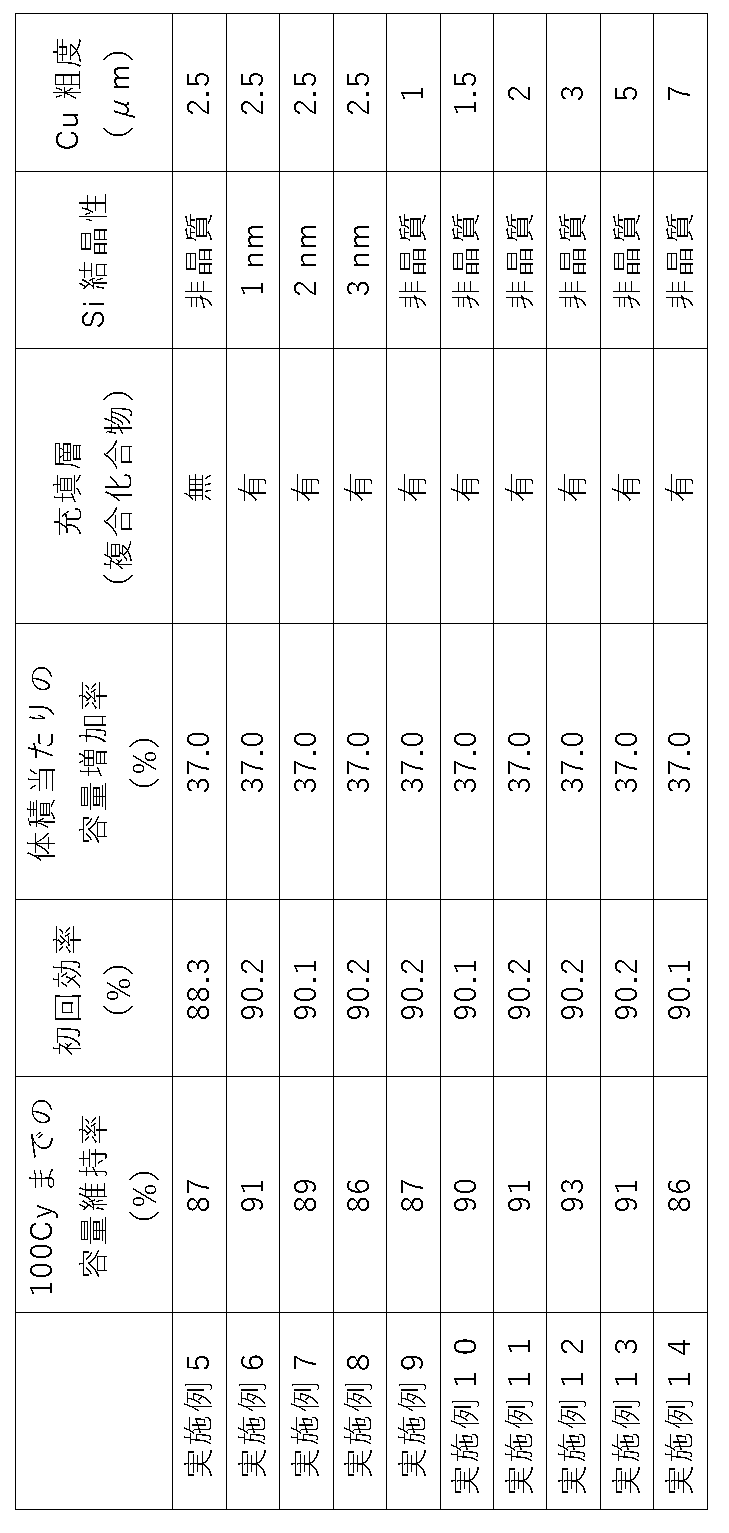
上記表1及び表2では、比較例1に対する体積当たりの放電容量(Wh/L)の増加率を、容量増加率として示している。
Claims (10)
- 表面が粗化された負極集電体と、
該負極集電体上に設けられた負極活物質層と
を有する負極であって、
前記負極活物質層は、リチウム、ケイ素、及び酸素の化合物を有する負極活物質粒子を含み、前記負極活物質粒子を構成する前記酸素と前記ケイ素との比O/Siが0.8以上1.2以下の範囲であり、
該負極活物質層は、2層以上からなる多層構造を有しており、前記負極活物質層の多層構造の各層は、上部に、リチウム及び酸素のうち少なくとも1種類以上を含む4価のケイ素の化合物を含有する層を有しているものであることを特徴とする負極。 - 前記4価のケイ素の化合物は、SiO2及びLi4SiO4から選ばれる1種類以上を含むものであることを特徴とする請求項1に記載の負極。
- 前記負極活物質層は、
前記負極活物質粒子と、
該負極活物質粒子の粒子間及び表層に充填されてなる、少なくとも炭素原子と酸素原子が化学結合しており、前記負極活物質粒子と合金化しない複合化合物と
を有するものであることを特徴とする請求項1又は2に記載の負極。 - 前記複合化合物は、エーテル系溶媒とポリフェニレン化合物若しくは多環芳香族化合物との複合物の開環分解生成物、又は前記複合物がリチウムと錯体を形成した複合物の開環分解生成物であることを特徴とする請求項3に記載の負極。
- 少なくとも20回充放電後の前記負極活物質粒子は、Si1+~Si3+のケイ素化合物状態が最も多いものであることを特徴とする請求項1から請求項4のいずれか1項に記載の負極。
- 前記負極活物質層は、前記負極活物質粒子を1次粒子として規定した場合、充放電後に該1次粒子の集合体である2次粒子を形成するものであり、該2次粒子同士は面内方向において分離した形態を持つことを特徴とする請求項1から請求項5のいずれか1項に負極。
- 前記負極活物質粒子は、充放電前において、Cu-Kα線を用いたX線回折により得られるSi(111)結晶面に起因するピークを有し、該結晶面に対応する結晶子サイズは1.0nm以下であることを特徴とする請求項1から請求項6のいずれか1項に記載の負極。
- 前記負極集電体は、前記表面の十点平均粗さRzが1.5μm以上5.0μm以下のものであることを特徴とする請求項1から請求項7のいずれか1項に記載の負極。
- 請求項1から請求項8のいずれか1項に記載の負極の製造方法であって、
曲率を有するキャンロール上に前記負極集電体を巻き付ける工程と、
前記キャンロール上で前記負極集電体を走行させながら、前記負極集電体上に、2層以上からなる多層構造のケイ素及び/又は一酸化ケイ素を含む膜を気相成長させる工程と、
酸素を含んだガスを前記ケイ素及び/又は一酸化ケイ素を含む膜に吹き付けて、各層の上部に二酸化ケイ素を含有する多層構造の層を形成する工程と、
前記多層構造の層にリチウムをドープして、前記負極活物質層を形成する工程と
を含むことを特徴とする負極の製造方法。 - 前記多層構造の層を形成する工程において、前記二酸化ケイ素を含むケイ素酸化物を各層が含有する前記多層構造の層を形成し、
前記負極活物質層を形成する工程において、前記多層構造の層をリチウムを含む溶液に浸漬することによって、前記ケイ素酸化物を酸化還元法によって改質して、前記リチウム、ケイ素、及び酸素を有する化合物とするとともに、前記負極活物質粒子の粒子間及び表層に充填されてなる、少なくとも炭素原子と酸素原子が化学結合しており、前記負極活物質粒子と合金化しない複合化合物を形成することを特徴とする請求項9に記載の負極の製造方法。
Priority Applications (4)
| Application Number | Priority Date | Filing Date | Title |
|---|---|---|---|
| US18/682,628 US20240363840A1 (en) | 2021-08-16 | 2022-06-30 | Negative electrode and method for producing negative electrode |
| CN202280055864.6A CN117813701A (zh) | 2021-08-16 | 2022-06-30 | 负极及负极的制造方法 |
| KR1020247004917A KR20240042448A (ko) | 2021-08-16 | 2022-06-30 | 부극 및 부극의 제조 방법 |
| EP22858184.9A EP4391110A4 (en) | 2021-08-16 | 2022-06-30 | NEGATIVE ELECTRODE AND METHOD FOR PRODUCING NEGATIVE ELECTRODE |
Applications Claiming Priority (2)
| Application Number | Priority Date | Filing Date | Title |
|---|---|---|---|
| JP2021-132227 | 2021-08-16 | ||
| JP2021132227A JP7637599B2 (ja) | 2021-08-16 | 2021-08-16 | 負極及び負極の製造方法 |
Publications (1)
| Publication Number | Publication Date |
|---|---|
| WO2023021861A1 true WO2023021861A1 (ja) | 2023-02-23 |
Family
ID=85240508
Family Applications (1)
| Application Number | Title | Priority Date | Filing Date |
|---|---|---|---|
| PCT/JP2022/026347 Ceased WO2023021861A1 (ja) | 2021-08-16 | 2022-06-30 | 負極及び負極の製造方法 |
Country Status (7)
| Country | Link |
|---|---|
| US (1) | US20240363840A1 (ja) |
| EP (1) | EP4391110A4 (ja) |
| JP (1) | JP7637599B2 (ja) |
| KR (1) | KR20240042448A (ja) |
| CN (1) | CN117813701A (ja) |
| TW (1) | TW202310474A (ja) |
| WO (1) | WO2023021861A1 (ja) |
Cited By (3)
| Publication number | Priority date | Publication date | Assignee | Title |
|---|---|---|---|---|
| WO2024154556A1 (ja) * | 2023-01-18 | 2024-07-25 | 信越化学工業株式会社 | 負極及び負極の製造方法 |
| DE102023202931A1 (de) * | 2023-03-30 | 2024-10-02 | Volkswagen Aktiengesellschaft | Beschichtungsvorrichtung, Verfahren und Elektrode |
| DE102023202928A1 (de) * | 2023-03-30 | 2024-10-02 | Volkswagen Aktiengesellschaft | Beschichtungsvorrichtung, Verfahren und Elektrode |
Families Citing this family (2)
| Publication number | Priority date | Publication date | Assignee | Title |
|---|---|---|---|---|
| JP2024170138A (ja) * | 2023-05-26 | 2024-12-06 | 信越化学工業株式会社 | 負極体及び負極体の製造方法 |
| CN119725498A (zh) * | 2025-01-03 | 2025-03-28 | 安徽得壹能源科技有限公司 | 一种硅碳负极材料、其制备方法及电池 |
Citations (19)
| Publication number | Priority date | Publication date | Assignee | Title |
|---|---|---|---|---|
| JPH06325765A (ja) | 1992-07-29 | 1994-11-25 | Seiko Instr Inc | 非水電解質二次電池及びその製造方法 |
| JP2001185127A (ja) | 1999-12-24 | 2001-07-06 | Fdk Corp | リチウム2次電池 |
| JP2002042806A (ja) | 2000-07-19 | 2002-02-08 | Japan Storage Battery Co Ltd | 非水電解質二次電池 |
| JP2005183264A (ja) * | 2003-12-22 | 2005-07-07 | Nec Corp | 二次電池用負極材料及びその製造方法並びにそれを用いた二次電池 |
| JP2006114454A (ja) | 2004-10-18 | 2006-04-27 | Sony Corp | 電池 |
| JP2006164954A (ja) | 2004-11-11 | 2006-06-22 | Matsushita Electric Ind Co Ltd | リチウムイオン二次電池用負極、その製造方法、およびそれを用いたリチウムイオン二次電池 |
| JP2006196447A (ja) * | 2004-12-16 | 2006-07-27 | Matsushita Electric Ind Co Ltd | リチウムイオン二次電池用負極、その製造方法、およびそれを用いたリチウムイオン二次電池 |
| JP2007207439A (ja) * | 2006-01-30 | 2007-08-16 | Sony Corp | 二次電池用負極及びそれを用いた二次電池 |
| JP2007234255A (ja) | 2006-02-27 | 2007-09-13 | Sanyo Electric Co Ltd | リチウム二次電池用負極及びその製造方法並びにリチウム二次電池 |
| JP2008177346A (ja) | 2007-01-18 | 2008-07-31 | Sanyo Electric Co Ltd | エネルギー貯蔵デバイス |
| JP2008251369A (ja) | 2007-03-30 | 2008-10-16 | Matsushita Electric Ind Co Ltd | リチウム二次電池用負極およびそれを備えたリチウム二次電池、ならびにリチウム二次電池用負極の製造方法 |
| JP2008282819A (ja) | 2008-07-10 | 2008-11-20 | Toshiba Corp | 非水電解質二次電池用負極活物質の製造方法およびこれによって得られる非水電解質電池用負極活物質 |
| JP2009070825A (ja) | 2007-09-17 | 2009-04-02 | Samsung Sdi Co Ltd | リチウム2次電池用負極活物質とその製造方法、リチウム2次電池用負極及びリチウム2次電池 |
| JP2009205950A (ja) | 2008-02-28 | 2009-09-10 | Shin Etsu Chem Co Ltd | 非水電解質二次電池用負極活物質、及びそれを用いた非水電解質二次電池 |
| JP2009212074A (ja) | 2008-02-07 | 2009-09-17 | Shin Etsu Chem Co Ltd | 非水電解質二次電池用負極材及びその製造方法並びにリチウムイオン二次電池及び電気化学キャパシタ |
| JP2015156355A (ja) | 2013-08-21 | 2015-08-27 | 信越化学工業株式会社 | 負極活物質、負極活物質材料、負極電極、リチウムイオン二次電池、負極電極の製造方法、負極活物質の製造方法、並びに、リチウムイオン二次電池の製造方法 |
| JP2016225199A (ja) * | 2015-06-02 | 2016-12-28 | 信越化学工業株式会社 | 非水電解質二次電池用負極活物質、非水電解質二次電池用負極、及び非水電解質二次電池、並びに負極活物質粒子の製造方法 |
| JP2017152375A (ja) * | 2016-02-23 | 2017-08-31 | 信越化学工業株式会社 | 負極活物質、混合負極活物質材料、非水電解質二次電池用負極、リチウムイオン二次電池用負極、リチウムイオン二次電池、負極活物質の製造方法、負極の製造方法、及びリチウムイオン二次電池の製造方法 |
| JP2020140896A (ja) * | 2019-02-28 | 2020-09-03 | 積水化学工業株式会社 | リチウムイオン二次電池用電極及びリチウムイオン二次電池 |
Family Cites Families (3)
| Publication number | Priority date | Publication date | Assignee | Title |
|---|---|---|---|---|
| US20150221950A1 (en) * | 2012-09-27 | 2015-08-06 | Sanyo Electric Co., Ltd. | Negative electrode active material for non-aqueous electrolyte secondary batteries and non-aqueous electrolyte secondary battery using negative electrode active material |
| US10879531B2 (en) * | 2015-10-26 | 2020-12-29 | Lg Chem, Ltd. | Negative electrode active particle and method for manufacturing the same |
| EP3958349A4 (en) * | 2019-04-19 | 2022-07-13 | Panasonic Holdings Corporation | Negative electrode for non-aqueous electrolyte secondary battery and non-aqueous electrolyte secondary battery |
-
2021
- 2021-08-16 JP JP2021132227A patent/JP7637599B2/ja active Active
-
2022
- 2022-06-30 WO PCT/JP2022/026347 patent/WO2023021861A1/ja not_active Ceased
- 2022-06-30 KR KR1020247004917A patent/KR20240042448A/ko active Pending
- 2022-06-30 CN CN202280055864.6A patent/CN117813701A/zh active Pending
- 2022-06-30 EP EP22858184.9A patent/EP4391110A4/en not_active Withdrawn
- 2022-06-30 US US18/682,628 patent/US20240363840A1/en active Pending
- 2022-07-06 TW TW111125304A patent/TW202310474A/zh unknown
Patent Citations (19)
| Publication number | Priority date | Publication date | Assignee | Title |
|---|---|---|---|---|
| JPH06325765A (ja) | 1992-07-29 | 1994-11-25 | Seiko Instr Inc | 非水電解質二次電池及びその製造方法 |
| JP2001185127A (ja) | 1999-12-24 | 2001-07-06 | Fdk Corp | リチウム2次電池 |
| JP2002042806A (ja) | 2000-07-19 | 2002-02-08 | Japan Storage Battery Co Ltd | 非水電解質二次電池 |
| JP2005183264A (ja) * | 2003-12-22 | 2005-07-07 | Nec Corp | 二次電池用負極材料及びその製造方法並びにそれを用いた二次電池 |
| JP2006114454A (ja) | 2004-10-18 | 2006-04-27 | Sony Corp | 電池 |
| JP2006164954A (ja) | 2004-11-11 | 2006-06-22 | Matsushita Electric Ind Co Ltd | リチウムイオン二次電池用負極、その製造方法、およびそれを用いたリチウムイオン二次電池 |
| JP2006196447A (ja) * | 2004-12-16 | 2006-07-27 | Matsushita Electric Ind Co Ltd | リチウムイオン二次電池用負極、その製造方法、およびそれを用いたリチウムイオン二次電池 |
| JP2007207439A (ja) * | 2006-01-30 | 2007-08-16 | Sony Corp | 二次電池用負極及びそれを用いた二次電池 |
| JP2007234255A (ja) | 2006-02-27 | 2007-09-13 | Sanyo Electric Co Ltd | リチウム二次電池用負極及びその製造方法並びにリチウム二次電池 |
| JP2008177346A (ja) | 2007-01-18 | 2008-07-31 | Sanyo Electric Co Ltd | エネルギー貯蔵デバイス |
| JP2008251369A (ja) | 2007-03-30 | 2008-10-16 | Matsushita Electric Ind Co Ltd | リチウム二次電池用負極およびそれを備えたリチウム二次電池、ならびにリチウム二次電池用負極の製造方法 |
| JP2009070825A (ja) | 2007-09-17 | 2009-04-02 | Samsung Sdi Co Ltd | リチウム2次電池用負極活物質とその製造方法、リチウム2次電池用負極及びリチウム2次電池 |
| JP2009212074A (ja) | 2008-02-07 | 2009-09-17 | Shin Etsu Chem Co Ltd | 非水電解質二次電池用負極材及びその製造方法並びにリチウムイオン二次電池及び電気化学キャパシタ |
| JP2009205950A (ja) | 2008-02-28 | 2009-09-10 | Shin Etsu Chem Co Ltd | 非水電解質二次電池用負極活物質、及びそれを用いた非水電解質二次電池 |
| JP2008282819A (ja) | 2008-07-10 | 2008-11-20 | Toshiba Corp | 非水電解質二次電池用負極活物質の製造方法およびこれによって得られる非水電解質電池用負極活物質 |
| JP2015156355A (ja) | 2013-08-21 | 2015-08-27 | 信越化学工業株式会社 | 負極活物質、負極活物質材料、負極電極、リチウムイオン二次電池、負極電極の製造方法、負極活物質の製造方法、並びに、リチウムイオン二次電池の製造方法 |
| JP2016225199A (ja) * | 2015-06-02 | 2016-12-28 | 信越化学工業株式会社 | 非水電解質二次電池用負極活物質、非水電解質二次電池用負極、及び非水電解質二次電池、並びに負極活物質粒子の製造方法 |
| JP2017152375A (ja) * | 2016-02-23 | 2017-08-31 | 信越化学工業株式会社 | 負極活物質、混合負極活物質材料、非水電解質二次電池用負極、リチウムイオン二次電池用負極、リチウムイオン二次電池、負極活物質の製造方法、負極の製造方法、及びリチウムイオン二次電池の製造方法 |
| JP2020140896A (ja) * | 2019-02-28 | 2020-09-03 | 積水化学工業株式会社 | リチウムイオン二次電池用電極及びリチウムイオン二次電池 |
Non-Patent Citations (8)
| Title |
|---|
| "Newsletter ''Denchi (battery", BATTERY ASSOCIATION OF JAPAN, 1 May 2010 (2010-05-01), pages 10 |
| "The Latest Development Trends on Lithium-ion Batteries for xEV", 27 November 2020, CMC PUBLISHING, pages: 96 - 111 |
| A. HOHLT. WIEDERP. A. VAN AKENT. E. WEIRICHG. DENNINGERM. VIDALS. OSWALDC. DENEKEJ. MAYERH. FUESS, J. NON-CRYST. SOLIDS, vol. 320, 2003, pages 255 |
| HYE JIN KIMSUNGHUN CHOISEUNG JONG LEEMYUNG WON SEOJAE GOO LEEERHAN DENIZYONG JU LEEEUN KYUNG KIMJANG WOOK CHOI, NANO LETT., vol. 16, 2016, pages 282 - 288 |
| M. YAMADAM. INABAA. UEDAK. MATSUMOTOT. IWASAKIT. OHZUKU, J.ELECTROCHEM. SOC., vol. 159, 2012, pages A1630 |
| MARIKO MIYACHIHIRONORI YAMAMOTOHIDEMASA KAWAI, J. ELECTROCHEM. SOC., vol. 154, no. 4, 2007, pages A1112 - A1117 |
| See also references of EP4391110A4 |
| V. KAPAKLIS, J. NON-CRYSTALLINE SOLIDS, vol. 354, 2008, pages 612 |
Cited By (4)
| Publication number | Priority date | Publication date | Assignee | Title |
|---|---|---|---|---|
| WO2024154556A1 (ja) * | 2023-01-18 | 2024-07-25 | 信越化学工業株式会社 | 負極及び負極の製造方法 |
| JP2024101820A (ja) * | 2023-01-18 | 2024-07-30 | 信越化学工業株式会社 | 負極及び負極の製造方法 |
| DE102023202931A1 (de) * | 2023-03-30 | 2024-10-02 | Volkswagen Aktiengesellschaft | Beschichtungsvorrichtung, Verfahren und Elektrode |
| DE102023202928A1 (de) * | 2023-03-30 | 2024-10-02 | Volkswagen Aktiengesellschaft | Beschichtungsvorrichtung, Verfahren und Elektrode |
Also Published As
| Publication number | Publication date |
|---|---|
| KR20240042448A (ko) | 2024-04-02 |
| US20240363840A1 (en) | 2024-10-31 |
| TW202310474A (zh) | 2023-03-01 |
| JP7637599B2 (ja) | 2025-02-28 |
| EP4391110A4 (en) | 2026-01-21 |
| CN117813701A (zh) | 2024-04-02 |
| JP2023026832A (ja) | 2023-03-01 |
| EP4391110A1 (en) | 2024-06-26 |
Similar Documents
| Publication | Publication Date | Title |
|---|---|---|
| JP7410259B2 (ja) | 非水電解質二次電池 | |
| JP7637599B2 (ja) | 負極及び負極の製造方法 | |
| JP7368577B2 (ja) | 負極及びその製造方法 | |
| JP7490590B2 (ja) | 負極及び負極の製造方法 | |
| WO2022239676A1 (ja) | 負極活物質及びその製造方法 | |
| WO2018051710A1 (ja) | 負極活物質、混合負極活物質材料、及び負極活物質の製造方法 | |
| JP2025066575A (ja) | 負極活物質及びその製造方法 | |
| WO2023135970A1 (ja) | 負極活物質及び負極 | |
| JP7653862B2 (ja) | 負極 | |
| JP7325458B2 (ja) | 非水電解質二次電池用負極活物質及び非水電解質二次電池用負極活物質の製造方法 | |
| US20250210654A1 (en) | Negative electrode active material and method for producing negative electrode active material | |
| US20240375968A1 (en) | Negative electrode and method for manufacturing the same | |
| JP2024101820A (ja) | 負極及び負極の製造方法 |
Legal Events
| Date | Code | Title | Description |
|---|---|---|---|
| 121 | Ep: the epo has been informed by wipo that ep was designated in this application |
Ref document number: 22858184 Country of ref document: EP Kind code of ref document: A1 |
|
| WWE | Wipo information: entry into national phase |
Ref document number: 202280055864.6 Country of ref document: CN |
|
| WWE | Wipo information: entry into national phase |
Ref document number: 2022858184 Country of ref document: EP |
|
| NENP | Non-entry into the national phase |
Ref country code: DE |
|
| ENP | Entry into the national phase |
Ref document number: 2022858184 Country of ref document: EP Effective date: 20240318 |
|
| WWW | Wipo information: withdrawn in national office |
Ref document number: 2022858184 Country of ref document: EP |