WO2023022208A1 - 中空糸膜モジュールユニット - Google Patents
中空糸膜モジュールユニット Download PDFInfo
- Publication number
- WO2023022208A1 WO2023022208A1 PCT/JP2022/031281 JP2022031281W WO2023022208A1 WO 2023022208 A1 WO2023022208 A1 WO 2023022208A1 JP 2022031281 W JP2022031281 W JP 2022031281W WO 2023022208 A1 WO2023022208 A1 WO 2023022208A1
- Authority
- WO
- WIPO (PCT)
- Prior art keywords
- fiber membrane
- hollow fiber
- header tube
- module unit
- membrane module
- Prior art date
- Legal status (The legal status is an assumption and is not a legal conclusion. Google has not performed a legal analysis and makes no representation as to the accuracy of the status listed.)
- Ceased
Links
Images



Classifications
-
- B—PERFORMING OPERATIONS; TRANSPORTING
- B01—PHYSICAL OR CHEMICAL PROCESSES OR APPARATUS IN GENERAL
- B01D—SEPARATION
- B01D63/00—Apparatus in general for separation processes using semi-permeable membranes
- B01D63/02—Hollow fibre modules
- B01D63/04—Hollow fibre modules comprising multiple hollow fibre assemblies
- B01D63/043—Hollow fibre modules comprising multiple hollow fibre assemblies with separate tube sheets
-
- B—PERFORMING OPERATIONS; TRANSPORTING
- B01—PHYSICAL OR CHEMICAL PROCESSES OR APPARATUS IN GENERAL
- B01D—SEPARATION
- B01D63/00—Apparatus in general for separation processes using semi-permeable membranes
- B01D63/02—Hollow fibre modules
- B01D63/04—Hollow fibre modules comprising multiple hollow fibre assemblies
- B01D63/046—Hollow fibre modules comprising multiple hollow fibre assemblies in separate housings
-
- A—HUMAN NECESSITIES
- A01—AGRICULTURE; FORESTRY; ANIMAL HUSBANDRY; HUNTING; TRAPPING; FISHING
- A01K—ANIMAL HUSBANDRY; AVICULTURE; APICULTURE; PISCICULTURE; FISHING; REARING OR BREEDING ANIMALS, NOT OTHERWISE PROVIDED FOR; NEW BREEDS OF ANIMALS
- A01K63/00—Receptacles for live fish, e.g. aquaria; Terraria
- A01K63/04—Arrangements for treating water specially adapted to receptacles for live fish
-
- B—PERFORMING OPERATIONS; TRANSPORTING
- B01—PHYSICAL OR CHEMICAL PROCESSES OR APPARATUS IN GENERAL
- B01D—SEPARATION
- B01D65/00—Accessories or auxiliary operations, in general, for separation processes or apparatus using semi-permeable membranes
- B01D65/02—Membrane cleaning or sterilisation ; Membrane regeneration
-
- B—PERFORMING OPERATIONS; TRANSPORTING
- B01—PHYSICAL OR CHEMICAL PROCESSES OR APPARATUS IN GENERAL
- B01D—SEPARATION
- B01D69/00—Semi-permeable membranes for separation processes or apparatus characterised by their form, structure or properties; Manufacturing processes specially adapted therefor
- B01D69/08—Hollow fibre membranes
-
- B—PERFORMING OPERATIONS; TRANSPORTING
- B01—PHYSICAL OR CHEMICAL PROCESSES OR APPARATUS IN GENERAL
- B01D—SEPARATION
- B01D2313/00—Details relating to membrane modules or apparatus
- B01D2313/02—Specific tightening or locking mechanisms
-
- B—PERFORMING OPERATIONS; TRANSPORTING
- B01—PHYSICAL OR CHEMICAL PROCESSES OR APPARATUS IN GENERAL
- B01D—SEPARATION
- B01D2313/00—Details relating to membrane modules or apparatus
- B01D2313/02—Specific tightening or locking mechanisms
- B01D2313/025—Specific membrane holders
-
- B—PERFORMING OPERATIONS; TRANSPORTING
- B01—PHYSICAL OR CHEMICAL PROCESSES OR APPARATUS IN GENERAL
- B01D—SEPARATION
- B01D2313/00—Details relating to membrane modules or apparatus
- B01D2313/10—Specific supply elements
- B01D2313/105—Supply manifolds
-
- B—PERFORMING OPERATIONS; TRANSPORTING
- B01—PHYSICAL OR CHEMICAL PROCESSES OR APPARATUS IN GENERAL
- B01D—SEPARATION
- B01D2313/00—Details relating to membrane modules or apparatus
- B01D2313/12—Specific discharge elements
- B01D2313/125—Discharge manifolds
-
- B—PERFORMING OPERATIONS; TRANSPORTING
- B01—PHYSICAL OR CHEMICAL PROCESSES OR APPARATUS IN GENERAL
- B01D—SEPARATION
- B01D2313/00—Details relating to membrane modules or apparatus
- B01D2313/21—Specific headers, end caps
-
- B—PERFORMING OPERATIONS; TRANSPORTING
- B01—PHYSICAL OR CHEMICAL PROCESSES OR APPARATUS IN GENERAL
- B01D—SEPARATION
- B01D2313/00—Details relating to membrane modules or apparatus
- B01D2313/54—Modularity of membrane module elements
-
- B—PERFORMING OPERATIONS; TRANSPORTING
- B01—PHYSICAL OR CHEMICAL PROCESSES OR APPARATUS IN GENERAL
- B01D—SEPARATION
- B01D2317/00—Membrane module arrangements within a plant or an apparatus
- B01D2317/04—Elements in parallel
-
- B—PERFORMING OPERATIONS; TRANSPORTING
- B01—PHYSICAL OR CHEMICAL PROCESSES OR APPARATUS IN GENERAL
- B01D—SEPARATION
- B01D2321/00—Details relating to membrane cleaning, regeneration, sterilization or to the prevention of fouling
- B01D2321/04—Backflushing
-
- B—PERFORMING OPERATIONS; TRANSPORTING
- B01—PHYSICAL OR CHEMICAL PROCESSES OR APPARATUS IN GENERAL
- B01D—SEPARATION
- B01D2321/00—Details relating to membrane cleaning, regeneration, sterilization or to the prevention of fouling
- B01D2321/16—Use of chemical agents
Definitions
- the present invention relates to a hollow fiber membrane module unit composed of a plurality of hollow fiber membrane modules.
- Patent Literature 1 and Patent Literature 2 propose space-saving installation methods.
- a plurality of hollow fiber membrane modules are housed in a unit rack, and module caps and header tubes are assembled.
- a structure of a hollow fiber membrane module unit connected via a flexible hose is disclosed.
- Patent Document 3 discloses a structure of a hollow fiber membrane module unit characterized by using a header tube cap in which a module cap and a header tube are integrated.
- a method of connecting the hollow fiber membrane module and the header tube cap and a method of suppressing the axial force applied to the connection are shown.
- Patent Document 3 does not show a method of connecting header tube caps or a method of suppressing the axial force applied to the connection portion of the header tube caps.
- the object of the present invention is to provide a hollow fiber membrane module unit compatible with the above.
- the present invention has the following configurations.
- a hollow fiber membrane module unit configured by arranging in parallel a plurality of hollow fiber membrane elements having header tube caps attached to both ends, the hollow fiber membrane element is attached to the permeate side, Adjacent header tube caps are connected to each other by a side seal connection covering the outer perimeter of the abutment surface, and the header tube caps on at least both ends of the row are fixed by support bars.
- Membrane module unit (2) The hollow fiber membrane module unit according to (1), wherein the adjacent header tube caps are connected to each other by a side seal connection covering the outer circumference of the abutment surface and a connection by a support bar.
- the support bar is located on the opposite side of the hollow fiber membrane element via the header tube cap. unit.
- the connection between the header tube caps is performed by a side seal connection covering the outer periphery of the contact surface and a support bar.
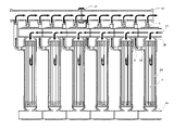
- FIG. 1 shows an embodiment of the hollow fiber membrane module unit of the present invention
- FIG. 1(a) is a schematic perspective view
- FIG. 1(b) is a schematic perspective view
- FIG. 2 is a schematic cross-sectional view showing one embodiment of the hollow fiber membrane element used in the present invention
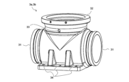
- FIG. 3 is a schematic perspective view showing one embodiment of a header tube cap used in the present invention
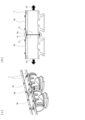
- FIG. 4 shows an embodiment of a method of connecting header tube caps used in the present invention, where (a) of FIG. 4 is a schematic perspective view and (b) of FIG. 4 is a schematic cross-sectional view
- FIG. 5 is a schematic flow chart showing one implementation method of filtration performed in the hollow fiber membrane module unit of the present invention.
- FIG. 6 is a schematic flow chart showing one implementation method of backwashing performed in the hollow fiber membrane module unit of the present invention.
- FIG. 7 is a schematic flow chart showing one implementation method of air washing performed in the hollow fiber membrane module unit of the present invention.
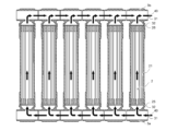
- FIG. 8 is a schematic top view showing one embodiment of the arrangement of side nozzles of the hollow fiber membrane element used in the present invention.
- the hollow fiber membrane module unit of the present invention is a hollow fiber membrane module unit configured by arranging in parallel a plurality of hollow fiber membrane elements having header tube caps attached to both ends, The adjacent header tube caps attached to the permeate side of the hollow fiber membrane element are connected to each other by a side seal connection covering the outer periphery of the abutment surface, and the header tube caps at least at both ends of the row. is fixed by a support bar.
- the hollow fiber membrane module unit of the present invention will be described below with reference to the drawings.
- the hollow fiber membrane module unit 1 of the present invention has a structure in which a plurality of hollow fiber membrane elements 2 are arranged in two rows.
- a T-shaped header tube cap 3a is attached to one end of the hollow fiber membrane element 2 by an element joint 4a.
- a T-shaped header pipe cap 3b is attached to the other end by an element joint 4b.
- Adjacent header tube caps 3a in the same row are connected by header tube cap joints 5a.
- the header tube caps 3b are connected to each other by a header tube cap joint 5b.
- some of the plurality of header pipe caps 3a arranged in a row are fastened to the pedestal 6 by bolts or the like.
- some of the plurality of header tube caps 3b arranged in a row are fastened to the support bar 7 with bolts or the like.
- a side nozzle 24 on the side surface of the hollow fiber membrane element 2 is connected to one end of a long elbow 8 bent at 90° by a side nozzle joint 9 .
- the other end of the long elbow 8 is installed so as to open parallel to the end on the side of the header tube cap 3b in the longitudinal direction of the hollow fiber membrane element. That is, it is installed so as to open in the positive direction of the Z-axis direction.
- the other end of the long elbow 8 is connected by a long elbow joint 11 to a manifold 10 having a plurality of branches on the outer peripheral surface of the straight pipe.
- the manifold 10 is arranged in the upper part in the Z-axis direction between the header tube caps 3b arranged in two rows so as to be parallel to the rows.
- the manifold 10 is fastened to the support bar 7 by bolts or the like, and is fitted and installed on the manifold base 12 attached so as to straddle two rows.
- a straight air pipe 13 is arranged between the hollow fiber membrane elements 2 arranged in two rows.
- the outer peripheral surface of the air pipe 13 is provided with the same number of through holes as the header pipe caps 3a to be connected. All the through holes are connected to the air injection through holes 33 (see FIG. 3) provided in the header tube cap 3a through the air tubes 14, respectively.
- the air pipe 13 is fitted and installed on the air pipe base 15 fitted and installed so as to straddle the hollow fiber membrane elements 2 arranged in two rows.
- the element joints 4a and 4b are combined with sealing materials (not shown) such as O-rings and gaskets to liquid-tightly connect the hollow fiber membrane element 2 and the ends 32 (end portions 32) of the branched portions of the header tube caps 3a and 3b. 3), any joint can be selected.
- sealing materials such as O-rings and gaskets to liquid-tightly connect the hollow fiber membrane element 2 and the ends 32 (end portions 32) of the branched portions of the header tube caps 3a and 3b. 3
- any joint can be selected.
- V-band coupling from the viewpoint that the hollow fiber membrane element 2 and the header tube caps 3a and 3b can be fastened in such a manner that they are brought into contact with each other in the axial direction, and rattling of the fastening portion and accompanying damage can be suppressed.
- the material can be arbitrarily selected according to the usage conditions and required strength, SUS304 and SUS316 are preferable from the viewpoint of pressure resistance and corrosion resistance.
- any joint can be selected.
- a side seal connection in which the connection length can be changed.
- Straub Coupling registered trademark
- the material can be arbitrarily selected according to the usage conditions and required strength, but glass fiber reinforced plastic is preferable from the viewpoint of pressure resistance, cost, weight, and moldability.
- the pedestal 6 may have any shape as long as it has a seat surface on which the header pipe cap 3a can be installed and a bolt through hole. can be set.
- one row of six hollow fiber membrane elements is stacked on one pedestal 6, but the shape can be changed as appropriate according to the required number of hollow fiber membrane elements 2, and the number of stacks can be arbitrarily set. It is selectable.
- one pedestal 6 may be used for one row of hollow fiber membrane elements, or one pedestal 6 may be used for two rows.
- the shape and material of the long elbow 8 can be arbitrarily selected as long as the hollow fiber membrane element 2 and the manifold 10 can be connected.
- metal pipes, plastic pipes, flexible hoses, and the like can be cited as candidates.
- plastic pipes are preferable because they can rigidly connect the hollow fiber membrane element 2 and the manifold 10, and are inexpensive and light in weight.
- PVC polyvinyl chloride
- PVC polyvinyl chloride
- the hollow fiber membrane element 2 is composed of a hollow fiber membrane bundle composed of a plurality of hollow fiber membranes 21 and a cylindrical container 22 containing the hollow fiber membrane bundle. Both ends of the hollow fiber membrane bundle and the cylindrical container 22 are liquid-tightly adhered and fixed by pottings 23a and 23b, respectively.
- the potting 23a has a through hole in its longitudinal direction. Also, in the potting 23a, the ends of the hollow fiber membranes 21 are buried and sealed in the potting 23a.
- the ends of the hollow fiber membranes 21 are made to open at the ends 26 of the hollow fiber membrane elements 2 on the permeate side.
- a side nozzle 24 is provided on the side surface of the cylindrical container 22 on the side of the potting 23b in the longitudinal direction.
- the hollow fiber membrane element 2 introduces a pressurized raw liquid from the through hole of the potting 23 a at the end 25 on the raw liquid side, The permeated liquid filtered by the fiber membrane 21 is discharged from the end 26 of the potting 23b.
- unfiltered concentrated liquid, washing air, and the like are discharged from the side nozzles 24 .
- header tube caps 3a, 3b used in the present invention will be described using the schematic perspective view of FIG.
- the header tube caps 3a and 3b are T-shaped and open in three directions, that is, an end portion 31 of the straight pipe portion and an end portion 32 of the branched portion.
- a separate air injection through-hole 33 is provided in the side surface of the header tube cap 3a.
- the air injection through-hole 33 is preferably threaded or otherwise processed so that it can be easily connected to the air tube 14 .
- the ends of the header tube caps 3a and 3b opposite to the ends 32 of the branched portions are flat.
- a bolt hole 34 is provided there, and by using this hole, the pedestal 6 or the support bar 7 can be fastened with a bolt or the like.
- the material be plastic, which can be manufactured into a complicated shape by injection molding, is inexpensive, and is light in weight.
- PVC is particularly preferable from the viewpoint of durability, weather resistance, and strength.
- header tube cap 3b will be described as an example, but the header tube cap 3a can also be described in the same way.
- Adjacent header pipe caps 3b are arranged so that the ends 31 of the straight pipe portions face each other, and the header pipe cap joints 5b are installed and connected so as to cover the outer peripheries of their contact surfaces.
- a rubber ring 16 as a sealing member for ensuring liquid tightness.
- the header tube cap joint 5b uses a side seal connection whose connection length can be changed from the viewpoint of allowing assembly errors caused by dimensional errors of the hollow fiber membrane element 2, the header tube cap 3b, and the like. That is, as shown in FIG. 4(b), if a side seal connection is used, it is possible to connect even when there is a gap between the ends 31 of the straight pipe portions of the adjacent header pipe caps 3b. Increases and decreases in the gap distance caused by assembly errors can be allowed within the range of possible distances.
- the side seal connection is a housing-type connection that seals the outer circumference of the contact surface of the connection pipe, as represented by Victriq Joint (registered trademark) manufactured by Victriq.
- the connection type includes a groove type having a groove in the pipe, a shoulder type having a convex portion, a ring type, strub coupling (registered trademark), and the like.
- the side seal connection used in the present invention is excellent in the ease and cost of molding the header tube cap to be connected, and has a wide allowable range of assembled length and angle.
- a groove-type connection in which a groove is provided in the portion is preferred.
- the material of the header tube cap joint 5b can be arbitrarily selected according to the usage conditions and required strength, but from the viewpoint of pressure resistance, cost, weight, and moldability, glass fiber reinforced plastic is preferable.
- the header pipe cap 3b may be displaced in the longitudinal direction of the straight pipe portion (the direction of arrow 35 in the figure) due to the load caused by the pressure and liquid flow during operation of the hollow fiber membrane module unit. will be displaced to That is, the header tube caps 3b are separated from each other, and a load acting in the direction of widening the gap acts to move them.
- the header tube cap 3b moves in this manner, the header tube cap 3b itself, the hollow fiber membrane element 2 connected to the header tube cap 3b, and other members may be deformed and damaged.
- the hollow fiber membrane module unit 1 of the present invention is characterized in that the use of the side seal connection ensures ease of assembly, while the use of the support bar 7 suppresses displacement and deformation of the header tube cap 3b.
- the support bar 7 is installed along the flat surface on the opposite side of the end 32 of the bifurcated portion of the header tube cap 3b so as to straddle the adjacent header tube caps 3b. Then, by using the bolt holes 34, the header pipe cap 3b and the support bar 7 are fastened with bolts or the like. As a result, the adjacent header tube caps 3b can be rigidly connected via the support bar 7, and displacement in the direction of the arrow 35 (moving direction of the header tube caps) can be suppressed.
- the header tube caps at both ends of the row of header tube caps should be fastened to the support bar 7 .
- the fastening points can be determined appropriately by taking into consideration the size of the hollow fiber membrane module, its assembling efficiency, and the cost.
- Fastening with the support bar 7 is preferable from the viewpoint of damage suppression. That is, it is preferable that the connection between the adjacent header tube caps is made by the side seal connection covering the outer periphery of the abutment surface and the connection by the support bar.
- the support bar 7 has a length that straddles a plurality of header tube caps 3b. It doesn't matter how long it is. It suffices if a fastening state in which displacement can be suppressed can be realized.
- the support bar 7 may be provided for each connecting portion of the adjacent header pipe caps 3b. Further, the number, shape, and arrangement position of the support bars 7 can be arbitrarily selected as long as the displacement and deformation of the header tube cap 3b and the leakage at the connecting portion can be suppressed.
- FIG. 4(a) shows a configuration in which two support bars 7 are arranged at both ends perpendicular to the longitudinal direction of the straight tube portion of the upper flat surface of the header tube cap 3b.
- the support bar 7 is positioned on the opposite side of the hollow fiber membrane element 2 via the header tube cap 3b as shown in FIG. 1(a). preferably.
- the material of the support bar 7 can be arbitrarily selected from metal, plastic, fiber-reinforced plastic, etc., according to the usage conditions and required strength.
- Stainless steel is preferable from the viewpoint of durability, and carbon fiber reinforced plastic is preferable from the viewpoint of lightness.
- 4(a) and 4(b) show a method of fixing the header tube cap 3b using the support bar 7, the base 6 is the same as the support bar 7 in fixing the header tube cap 3a. work and have the same effect.
- 2 flows into the hollow fiber membrane element 2 from the end 25 on the undiluted solution side.
- the stock solution that has flowed into the hollow fiber membrane element 2 is dead end filtered from the outer peripheral surface of the hollow fiber membrane 21 toward the inner periphery.
- each header tube cap 3b The permeated liquid that has flowed into each header tube cap 3b is collected in the straight tube portion of the connected and communicating header tube caps 3b, flows toward the header tube cap 3b at the end, and is discharged from the end.
- the channel connected to the side nozzle 24 (not shown) of the hollow fiber membrane element 2 is not used and is closed.
- FIG. 5 shows a flow in which the undiluted liquid is introduced from one end of the header tube cap 3a and the permeated liquid is discharged from one end of the header tube cap 3b. Liquid-tightness may be maintained by installing a lid or the like. In addition, it is also possible to introduce the undiluted liquid from both ends of the header pipe cap and to discharge the permeated liquid, considering the connection with the external piping (not shown).
- header pipe cap joints that is, side seal connections
- header pipe cap joints may be used in the same manner as the connection between the header pipe caps. It does not matter if it is connected after conversion, or it can be selected according to the situation of the external piping.
- the permeated liquid obtained in the operation of FIG. 5 is used as the washing liquid, and the washing liquid is introduced from the end of the header tube cap 3b located at the end.
- the introduced washing liquid flows through the straight pipe portions of the connected and communicating header pipe caps 3 b , and partly branches and flows into the hollow fiber membrane element 2 .
- the cleaning liquid that has flowed into the hollow fiber membrane element 2 permeates from the inner peripheral surface of the hollow fiber membrane 21 toward the outer periphery. At this time, the cleaning liquid is discharged to the outside of the hollow fiber membranes 21 while peeling off impurities adhering to the outer peripheral membrane surface.
- the channel connected to the header pipe cap 3a is not used and is closed.
- FIG. 6 shows the flow of introducing the cleaning liquid from one end of the header tube cap 3b and discharging the cleaning liquid from one end of the manifold 10.
- the header tube cap 3b and the other end of the manifold 10 are provided with a lid or the like. It is sufficient to maintain the liquid tightness by, for example, In addition, it is also possible to introduce the washing liquid from both ends of the header pipe cap 3b and to discharge it from both ends of the manifold 10, considering the connection with the external piping (not shown).
- the washing liquid flows into the manifold 10 not only from one row of the hollow fiber membrane elements shown in the figure, but also from another row, and the washing liquid for two rows of the hollow fiber membrane elements is collected and discharged.
- the manifold 10 has the number and length of branches that can be connected to 6 hollow fiber membrane elements (3 ⁇ 2 rows), but the number of branches depends on the required number of hollow fiber membrane elements and the ease of assembly. It can be selected as appropriate.
- the number of branches of the manifold 10 is 4 to 8 (2 to 4) considering that the weight of the manifold itself is within a range that can be handled manually, the number of connection points between manifolds, and the required number of manifold bases 12.
- a number of branches of (books x 2 rows) is preferred.
- manifold joints 17 are used to connect the manifolds 10 to each other. Any joint can be selected as the manifold joint 17 as long as it can connect the manifolds 10 in a liquid-tight manner together with a sealing material (not shown) such as an O-ring or a gasket. It is preferable to use a V-band coupling from the viewpoint that the coupling can be fastened with , and rattling of the fastening portion and damage associated therewith can be suppressed. Also, the material can be arbitrarily selected according to the usage conditions and required strength, but from the viewpoint of pressure resistance and corrosion resistance, SUS304 and SUS316 are preferable.
- the inside of the hollow fiber membrane element 2 is filled with the undiluted liquid or the permeated liquid, and then air is introduced.
- Air introduced from the end of the air pipe 13 flows through the air pipe 13, partly branches to a plurality of holes provided on the side surface of the cylindrical portion, passes through the air tube 14, and exits the air injection through hole 33. It flows into the header tube cap 3a.
- the inflowing air flows into the hollow fiber membrane element 2 from the branched portion of the header tube cap 3a.
- the inflowing air rises along the outer peripheral surface of the hollow fiber membrane 21, flows while peeling off impurities adhering to the membrane surface, passes through the side nozzle 24, the long elbow 8, and the manifold 10, and is collected in the connected and communicating manifold 10. and discharged from the end of the manifold 10 at the extreme end.
- the flow paths connected to the end portions 31 of the straight pipe portions of the header pipe caps 3a and 3b are not used and are sealed.
- FIGS. 5 to 7 show the flow of the fluid during each operation of the hollow fiber membrane module unit 1 of the present invention, but FIGS. It does not accurately indicate the orientation and engagement of the actual members. Please refer to FIG.
- the side nozzles 24 of the hollow fiber membrane element 2 used in the present invention will be described with reference to the schematic top view of FIG.
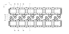
- the side nozzles 24 provided on the hollow fiber membrane elements 2 arranged in two rows are arranged between the rows in order to connect with the manifold 10 .
- the side nozzles 24 that form a pair in two rows are not arranged so as to face each other, but are arranged with their directions shifted from each other as shown in the figure.
- the reason for this is that the long elbows 8 connected to the side nozzles 24 via the side nozzle joints 9 can be efficiently arranged within the two rows of gaps, which is preferable from the viewpoint of space saving.
- the installation efficiency (membrane area per module installation unit area) is doubled or more compared to when the side nozzles 24 are installed so as to face each other. of 625 m 2 /m 2 .
- the branch portions of the manifold 10 connected to the long elbows 8 can be arranged at regular intervals, which is preferable from the viewpoint of water flow performance and assembly.
- a hollow fiber membrane module unit that can tolerate dimensional errors in each member that constitutes the hollow fiber membrane module unit and that can suppress displacement and deformation acting on the header tube cap while ensuring good assembly properties. can be provided.
- Hollow Fiber Membrane Module Unit 2 Hollow Fiber Membrane Elements 3a, 3b Header Tube Caps 4a, 4b Element Joints 5a, 5b Header Tube Cap Joints 6 Pedestal 7 Support Bar 8 Long Elbow 9 Side Nozzle Joint 10 Manifold 11 Long Elbow Joint 12 Manifold Base 13 Air pipe 14 Air tube 15 Air pipe base 16 Rubber ring 17 Manifold joint 21 Hollow fiber membrane 22 Cylindrical container 23a, 23b Potting 24 Side nozzle 25 End of hollow fiber membrane element on undiluted solution side 26 Permeate side of hollow fiber membrane element End 31 Straight tube end of header tube cap 32 Branched end of header tube cap 33 Air injection through hole 34 Bolt hole 35 Arrow 40 Arrow
Landscapes
- Chemical & Material Sciences (AREA)
- Chemical Kinetics & Catalysis (AREA)
- Life Sciences & Earth Sciences (AREA)
- Environmental Sciences (AREA)
- Marine Sciences & Fisheries (AREA)
- Animal Husbandry (AREA)
- Biodiversity & Conservation Biology (AREA)
- Separation Using Semi-Permeable Membranes (AREA)
Abstract
Description
(1)両端部にヘッダー管キャップが取り付けられた複数の中空糸膜エレメントが並列に列を成し構成される中空糸膜モジュールユニットにおいて、前記中空糸膜エレメントの透過液側に取り付けられた、隣接する前記ヘッダー管キャップ同士の接続が、当接面の外周を覆うサイドシール接続によって成され、前記列の少なくとも両端にある前記ヘッダー管キャップがサポートバーにより固定されることを特徴とする中空糸膜モジュールユニット。
(2)隣接する前記ヘッダー管キャップ同士の接続が、当接面の外周を覆うサイドシール接続およびサポートバーによる接続で成されることを特徴とする(1)に記載の中空糸膜モジュールユニット。
(3)前記サイドシール接続が、前記ヘッダー管キャップの接続部の外周部に溝を設けるグルーブ形式の接続であることを特徴とする(1)または(2)に記載の中空糸膜モジュールユニット。
(4)前記サポートバーが、前記ヘッダー管キャップを介し、前記中空糸膜エレメントの反対側に位置することを特徴とする(1)~(3)のいずれか1項に記載の中空糸膜モジュールユニット。
(5)前記サポートバーが、前記ヘッダー管キャップに対し、2列を成して設置されることを特徴とする(1)~(4)のいずれか1項に記載の中空糸膜モジュールユニット。
前記中空糸膜エレメントの透過液側に取り付けられた、隣接する前記ヘッダー管キャップ同士の接続が、当接面の外周を覆うサイドシール接続によって成され、前記列の少なくとも両端にある前記ヘッダー管キャップがサポートバーにより固定されることを特徴とする。
本発明の中空糸膜モジュールユニットを、図面を参照して以下に説明する。
このとき、列を成したヘッダー管キャップのうち、少なくとも両端にあるヘッダー管キャップは、サポートバー7と締結される必要がある。その一方で、両端を除くヘッダー管キャップとサポートバーの締結に関しては、中空糸膜モジュールのサイズやその組立性、コストを勘案して、適宜締結箇所を決めればよいが、ヘッダー管キャップすべてがそれぞれサポートバー7と締結される方が、破損抑制の観点から好ましい。すなわち、隣接するヘッダー管キャップ同士の接続が、当接面の外周を覆うサイドシール接続およびサポートバーによる接続で成されることが好ましい。
また、同様の観点から、サポートバー7を複数設置することが好ましく、ヘッダー管キャップに対し、2列を成して設置されることが好ましい。その場合、設置を接続部円周方向に均等にすることが好ましい。
図4の(a)に示すようなヘッダー管キャップ3bの上部のフラットな面の両端部に2本のサポートバー7を配置する構成であれば、ヘッダー管キャップ3bの変位抑制や接続部の漏れ防止の効果を確保しつつ、一方のサポートバー7をマニホールドベース12の座面としても使用することができるため、構造上好ましい。加えて、このような構造であれば、図4の(a)のようにサポートバー7を角柱のシンプルな形状にできるため、コストや取扱性、組立の容易さの観点から好ましい。また、図4に示すようにサポートバー7とヘッダー管キャップ3bを直接接触させて締結すると、両者の摩擦力によっても変位を抑制できるため、好ましい。
全量濾過を行うときは、中空糸膜エレメント2のサイドノズル24(図示せず)に繋がる流路は使用せず、封止しておく。
また、図5では、ヘッダー管キャップ3aの一端から原液を導入し、ヘッダー管キャップ3bの一端から透過液を排出する流れを示したが、この場合、ヘッダー管キャップ3aと3bの他端には蓋などを設置するなどして液密性を保てば良い。また、外部配管(図示せず)との取り合いを考慮し、適宜ヘッダー管キャップの両端から原液を導入したり、透過液を排出することも可能である。ヘッダー管キャップ3a、3bと外部配管との接続に関しては、ヘッダー管キャップ同士の接続と同様にヘッダー管キャップ継手(すなわち、サイドシール接続)を使用しても構わないし、サイドシール接続部をフランジに変換してから接続しても構わないし、適宜外部配管の状況に応じて選択可能である。
本出願は、2021年8月20日出願の日本特許出願(特願2021-134671)に基づくものであり、その内容はここに参照として取り込まれる。
2 中空糸膜エレメント
3a、3b ヘッダー管キャップ
4a、4b エレメント継手
5a、5b ヘッダー管キャップ継手
6 台座
7 サポートバー
8 ロングエルボ
9 サイドノズル継手
10 マニホールド
11 ロングエルボ継手
12 マニホールドベース
13 エアパイプ
14 エアチューブ
15 エアパイプベース
16 ゴムリング
17 マニホールド継手
21 中空糸膜
22 筒状容器
23a、23b ポッティング
24 サイドノズル
25 中空糸膜エレメントの原液側の端部
26 中空糸膜エレメントの透過液側の端部
31 ヘッダー管キャップの直管部の端部
32 ヘッダー管キャップの分岐部の端部
33 エア注入用貫通孔
34 ボルト穴
35 矢印
40 矢印
Claims (5)
- 両端部にヘッダー管キャップが取り付けられた複数の中空糸膜エレメントが並列に列を成し構成される中空糸膜モジュールユニットにおいて、
前記中空糸膜エレメントの透過液側に取り付けられた、隣接する前記ヘッダー管キャップ同士の接続が、当接面の外周を覆うサイドシール接続によって成され、前記列の少なくとも両端にある前記ヘッダー管キャップがサポートバーにより固定されることを特徴とする中空糸膜モジュールユニット。 - 隣接する前記ヘッダー管キャップ同士の接続が、当接面の外周を覆うサイドシール接続およびサポートバーによる接続で成されることを特徴とする請求項1に記載の中空糸膜モジュールユニット。
- 前記サイドシール接続が、前記ヘッダー管キャップの接続部の外周部に溝を設けるグルーブ形式の接続であることを特徴とする請求項1または2に記載の中空糸膜モジュールユニット。
- 前記サポートバーが、前記ヘッダー管キャップを介し、前記中空糸膜エレメントの反対側に位置することを特徴とする請求項1~3のいずれか1項に記載の中空糸膜モジュールユニット。
- 前記サポートバーが、前記ヘッダー管キャップに対し、2列を成して設置されることを特徴とする請求項1~4のいずれか1項に記載の中空糸膜モジュールユニット。
Priority Applications (6)
| Application Number | Priority Date | Filing Date | Title |
|---|---|---|---|
| KR1020247004568A KR102765085B1 (ko) | 2021-08-20 | 2022-08-18 | 중공사막 모듈 유닛 |
| JP2022551004A JP7359315B2 (ja) | 2021-08-20 | 2022-08-18 | 中空糸膜モジュールユニット |
| EP22858525.3A EP4368281A4 (en) | 2021-08-20 | 2022-08-18 | Hollow-fiber membrane module unit |
| CN202280056539.1A CN117897219B (zh) | 2021-08-20 | 2022-08-18 | 中空纤维膜组件单元 |
| US18/683,377 US12564814B2 (en) | 2021-08-20 | 2022-08-18 | Hollow-fiber membrane module unit |
| AU2022330672A AU2022330672B2 (en) | 2021-08-20 | 2022-08-18 | Hollow-fiber membrane module unit |
Applications Claiming Priority (2)
| Application Number | Priority Date | Filing Date | Title |
|---|---|---|---|
| JP2021-134671 | 2021-08-20 | ||
| JP2021134671 | 2021-08-20 |
Publications (1)
| Publication Number | Publication Date |
|---|---|
| WO2023022208A1 true WO2023022208A1 (ja) | 2023-02-23 |
Family
ID=85240858
Family Applications (1)
| Application Number | Title | Priority Date | Filing Date |
|---|---|---|---|
| PCT/JP2022/031281 Ceased WO2023022208A1 (ja) | 2021-08-20 | 2022-08-18 | 中空糸膜モジュールユニット |
Country Status (7)
| Country | Link |
|---|---|
| US (1) | US12564814B2 (ja) |
| EP (1) | EP4368281A4 (ja) |
| JP (1) | JP7359315B2 (ja) |
| KR (1) | KR102765085B1 (ja) |
| CN (1) | CN117897219B (ja) |
| AU (1) | AU2022330672B2 (ja) |
| WO (1) | WO2023022208A1 (ja) |
Families Citing this family (1)
| Publication number | Priority date | Publication date | Assignee | Title |
|---|---|---|---|---|
| KR20210132921A (ko) * | 2020-04-28 | 2021-11-05 | 주식회사 아모그린텍 | 중력식 정수장치용 필터모듈 및 이를 포함하는 중력식 정수장치 |
Citations (9)
| Publication number | Priority date | Publication date | Assignee | Title |
|---|---|---|---|---|
| JPH119969A (ja) * | 1997-06-27 | 1999-01-19 | Daisen Menburen Syst Kk | 中空糸膜モジュールおよび中空糸膜モジュール集合体 |
| EP1743690A1 (de) | 2005-07-11 | 2007-01-17 | inge AG | Filtrationsanlage mit mehreren vertikal in Reihe angeordneten Filtrationsmodulen |
| JP2009028716A (ja) | 2007-06-25 | 2009-02-12 | Asahi Kasei Chemicals Corp | 中空糸膜モジュールと、媒体集合ヘッダー管又は媒体注入ヘッダー管との接続構造 |
| JP2013052386A (ja) | 2011-08-09 | 2013-03-21 | Toray Ind Inc | 中空糸膜モジュールおよび中空糸膜モジュールユニット |
| JP2014528352A (ja) * | 2011-09-30 | 2014-10-27 | エヴォクア ウォーター テクノロジーズ エルエルシーEvoqua Water Technologiesllc | 改良したマニホルド構造 |
| US20160228822A1 (en) * | 2013-10-02 | 2016-08-11 | Evoqua Water Technologies Llc | A method and device for repairing a membrane filtration module |
| CN210522273U (zh) * | 2019-04-19 | 2020-05-15 | 苏州立升净水科技有限公司 | 滤芯组件及过滤装置 |
| JP2021500219A (ja) * | 2017-10-19 | 2021-01-07 | スリーエム イノベイティブ プロパティズ カンパニー | 一体型膜モジュールラック |
| JP2021134671A (ja) | 2020-02-25 | 2021-09-13 | 三菱重工業株式会社 | 遠心回転機械 |
Family Cites Families (16)
| Publication number | Priority date | Publication date | Assignee | Title |
|---|---|---|---|---|
| DE19719066C1 (de) * | 1997-05-06 | 1998-09-03 | Alia Engineering Ag | Rohrkupplung |
| KR20020042700A (ko) * | 2000-08-02 | 2002-06-05 | 히라이 가쯔히꼬 | 중공사막 모듈, 중공사막 모듈유닛 및 중공사막 모듈의제조방법 |
| US7712796B2 (en) * | 2004-05-14 | 2010-05-11 | Victaulic Company | Deformable mechanical pipe coupling |
| WO2006012920A1 (de) | 2004-07-29 | 2006-02-09 | Inge Ag | Filtrationsmembran sowie verfahren zur herstellung derselben |
| JP2008194680A (ja) | 2007-01-18 | 2008-08-28 | Asahi Kasei Chemicals Corp | 膜分離ユニット |
| CN101362053B (zh) | 2007-08-07 | 2012-10-10 | 厦门绿邦膜技术有限公司 | 一种中空纤维多孔膜过滤组件 |
| JP2009220010A (ja) | 2008-03-15 | 2009-10-01 | Toray Ind Inc | 中空糸膜エレメント用フレーム及び膜濾過装置 |
| US8136847B2 (en) * | 2009-05-14 | 2012-03-20 | Victaulic Company | Coupling having angularly oriented shoulder surfaces |
| JP5770990B2 (ja) * | 2010-09-22 | 2015-08-26 | 旭化成ケミカルズ株式会社 | 散気管、散気ユニット及び浸漬膜ユニット |
| CN201997263U (zh) | 2010-12-21 | 2011-10-05 | 旭化成化学株式会社 | 浸渍膜单元 |
| JP5730589B2 (ja) * | 2011-01-13 | 2015-06-10 | 旭化成ケミカルズ株式会社 | 管部材、流体移送管及び流体移送ユニット |
| US9534715B2 (en) * | 2012-01-20 | 2017-01-03 | Mueller International, Llc | Coupling gasket with multiple sealing surfaces |
| US9039046B2 (en) * | 2012-01-20 | 2015-05-26 | Mueller International, Llc | Coupling with tongue and groove |
| CN103224269B (zh) | 2013-04-28 | 2015-06-10 | 杭州水处理技术研究开发中心有限公司 | 一种双端产水的超滤膜组件 |
| CN206645872U (zh) * | 2017-03-24 | 2017-11-17 | 河北赛诺膜技术有限公司 | 一种模块化积木式膜装置 |
| WO2021101614A1 (en) * | 2019-11-21 | 2021-05-27 | Hydranautics | Modular manifold for filtration modules |
-
2022
- 2022-08-18 CN CN202280056539.1A patent/CN117897219B/zh active Active
- 2022-08-18 WO PCT/JP2022/031281 patent/WO2023022208A1/ja not_active Ceased
- 2022-08-18 KR KR1020247004568A patent/KR102765085B1/ko active Active
- 2022-08-18 JP JP2022551004A patent/JP7359315B2/ja active Active
- 2022-08-18 EP EP22858525.3A patent/EP4368281A4/en active Pending
- 2022-08-18 US US18/683,377 patent/US12564814B2/en active Active
- 2022-08-18 AU AU2022330672A patent/AU2022330672B2/en active Active
Patent Citations (9)
| Publication number | Priority date | Publication date | Assignee | Title |
|---|---|---|---|---|
| JPH119969A (ja) * | 1997-06-27 | 1999-01-19 | Daisen Menburen Syst Kk | 中空糸膜モジュールおよび中空糸膜モジュール集合体 |
| EP1743690A1 (de) | 2005-07-11 | 2007-01-17 | inge AG | Filtrationsanlage mit mehreren vertikal in Reihe angeordneten Filtrationsmodulen |
| JP2009028716A (ja) | 2007-06-25 | 2009-02-12 | Asahi Kasei Chemicals Corp | 中空糸膜モジュールと、媒体集合ヘッダー管又は媒体注入ヘッダー管との接続構造 |
| JP2013052386A (ja) | 2011-08-09 | 2013-03-21 | Toray Ind Inc | 中空糸膜モジュールおよび中空糸膜モジュールユニット |
| JP2014528352A (ja) * | 2011-09-30 | 2014-10-27 | エヴォクア ウォーター テクノロジーズ エルエルシーEvoqua Water Technologiesllc | 改良したマニホルド構造 |
| US20160228822A1 (en) * | 2013-10-02 | 2016-08-11 | Evoqua Water Technologies Llc | A method and device for repairing a membrane filtration module |
| JP2021500219A (ja) * | 2017-10-19 | 2021-01-07 | スリーエム イノベイティブ プロパティズ カンパニー | 一体型膜モジュールラック |
| CN210522273U (zh) * | 2019-04-19 | 2020-05-15 | 苏州立升净水科技有限公司 | 滤芯组件及过滤装置 |
| JP2021134671A (ja) | 2020-02-25 | 2021-09-13 | 三菱重工業株式会社 | 遠心回転機械 |
Non-Patent Citations (1)
| Title |
|---|
| See also references of EP4368281A4 |
Also Published As
| Publication number | Publication date |
|---|---|
| CN117897219A (zh) | 2024-04-16 |
| KR20240046493A (ko) | 2024-04-09 |
| EP4368281A1 (en) | 2024-05-15 |
| JP7359315B2 (ja) | 2023-10-11 |
| US12564814B2 (en) | 2026-03-03 |
| KR102765085B1 (ko) | 2025-02-06 |
| AU2022330672B2 (en) | 2024-07-04 |
| EP4368281A4 (en) | 2024-12-04 |
| CN117897219B (zh) | 2025-05-06 |
| JPWO2023022208A1 (ja) | 2023-02-23 |
| AU2022330672A1 (en) | 2024-02-22 |
| US20240325980A1 (en) | 2024-10-03 |
Similar Documents
| Publication | Publication Date | Title |
|---|---|---|
| ES2247743T3 (es) | Dispositivo para la separacion de liquidos. | |
| KR20160102201A (ko) | 중공사막 모듈 | |
| AU2013101711A4 (en) | Hollow fiber membrane module and hollow fiber membrane module unit | |
| AU2008349154B2 (en) | Hollow yarn film element, frame for hollow yarn film element, and filtration film device | |
| WO2013136903A1 (ja) | カートリッジ型中空糸膜モジュール | |
| US6592152B1 (en) | Joint structure for filtration membrane module | |
| CN107921375A (zh) | 用于借助对流模式扩散透析的缠绕式膜模块和方法 | |
| JP7359315B2 (ja) | 中空糸膜モジュールユニット | |
| CN101332412A (zh) | 中空纤维膜组件与介质集合集管和介质注入集管中的至少一种集管的连接构造 | |
| JP3272847B2 (ja) | 複数結合型中空糸膜モジュール | |
| JP3616131B2 (ja) | 分離膜モジュールおよび円筒体接続具 | |
| JP5730589B2 (ja) | 管部材、流体移送管及び流体移送ユニット | |
| CN102564164A (zh) | 一种可拆卸冷凝器 | |
| JP3713343B2 (ja) | 継ぎ手を有する濾過膜カートリッジ | |
| CN215141088U (zh) | 一种便于安装拆卸的喷淋管 | |
| JP4688141B2 (ja) | 液体分離装置 | |
| US8628662B2 (en) | Filtering device comprising membrane filtering modules and assembly of modules for such a device | |
| CN214171551U (zh) | 一种防变形的钢带增强聚乙烯螺旋波纹管 | |
| WO2011016477A1 (ja) | 海水淡水化装置 | |
| CN222605973U (zh) | 一种快速拼装柱式膜组件和膜过滤装备系统 | |
| CN219828106U (zh) | 管道接头结构 | |
| CN212640036U (zh) | 一种插管式平板膜过滤装置 | |
| JPH029876Y2 (ja) | ||
| CN217264973U (zh) | 模块化陶瓷膜滤芯 | |
| JPH119969A (ja) | 中空糸膜モジュールおよび中空糸膜モジュール集合体 |
Legal Events
| Date | Code | Title | Description |
|---|---|---|---|
| ENP | Entry into the national phase |
Ref document number: 2022551004 Country of ref document: JP Kind code of ref document: A |
|
| 121 | Ep: the epo has been informed by wipo that ep was designated in this application |
Ref document number: 22858525 Country of ref document: EP Kind code of ref document: A1 |
|
| WWE | Wipo information: entry into national phase |
Ref document number: AU2022330672 Country of ref document: AU |
|
| WWE | Wipo information: entry into national phase |
Ref document number: 2022858525 Country of ref document: EP |
|
| WWE | Wipo information: entry into national phase |
Ref document number: 18683377 Country of ref document: US |
|
| ENP | Entry into the national phase |
Ref document number: 2022858525 Country of ref document: EP Effective date: 20240208 |
|
| WWE | Wipo information: entry into national phase |
Ref document number: 202280056539.1 Country of ref document: CN |
|
| ENP | Entry into the national phase |
Ref document number: 2022330672 Country of ref document: AU Date of ref document: 20220818 Kind code of ref document: A |
|
| NENP | Non-entry into the national phase |
Ref country code: DE |
|
| WWG | Wipo information: grant in national office |
Ref document number: 202280056539.1 Country of ref document: CN |
|
| WWG | Wipo information: grant in national office |
Ref document number: 18683377 Country of ref document: US |