WO2023026512A1 - 搬送システム - Google Patents
搬送システム Download PDFInfo
- Publication number
- WO2023026512A1 WO2023026512A1 PCT/JP2022/002459 JP2022002459W WO2023026512A1 WO 2023026512 A1 WO2023026512 A1 WO 2023026512A1 JP 2022002459 W JP2022002459 W JP 2022002459W WO 2023026512 A1 WO2023026512 A1 WO 2023026512A1
- Authority
- WO
- WIPO (PCT)
- Prior art keywords
- truck
- state
- communication
- transport system
- operating state
- Prior art date
- Legal status (The legal status is an assumption and is not a legal conclusion. Google has not performed a legal analysis and makes no representation as to the accuracy of the status listed.)
- Ceased
Links
Images


Classifications
-
- G—PHYSICS
- G05—CONTROLLING; REGULATING
- G05D—SYSTEMS FOR CONTROLLING OR REGULATING NON-ELECTRIC VARIABLES
- G05D1/00—Control of position, course, altitude or attitude of land, water, air or space vehicles, e.g. using automatic pilots
- G05D1/60—Intended control result
- G05D1/69—Coordinated control of the position or course of two or more vehicles
- G05D1/698—Control allocation
- G05D1/6987—Control allocation by centralised control off-board any of the vehicles
-
- B—PERFORMING OPERATIONS; TRANSPORTING
- B65—CONVEYING; PACKING; STORING; HANDLING THIN OR FILAMENTARY MATERIAL
- B65G—TRANSPORT OR STORAGE DEVICES, e.g. CONVEYORS FOR LOADING OR TIPPING, SHOP CONVEYOR SYSTEMS OR PNEUMATIC TUBE CONVEYORS
- B65G1/00—Storing articles, individually or in orderly arrangement, in warehouses or magazines
- B65G1/02—Storage devices
- B65G1/04—Storage devices mechanical
- B65G1/0492—Storage devices mechanical with cars adapted to travel in storage aisles
-
- B—PERFORMING OPERATIONS; TRANSPORTING
- B65—CONVEYING; PACKING; STORING; HANDLING THIN OR FILAMENTARY MATERIAL
- B65G—TRANSPORT OR STORAGE DEVICES, e.g. CONVEYORS FOR LOADING OR TIPPING, SHOP CONVEYOR SYSTEMS OR PNEUMATIC TUBE CONVEYORS
- B65G1/00—Storing articles, individually or in orderly arrangement, in warehouses or magazines
- B65G1/02—Storage devices
- B65G1/04—Storage devices mechanical
- B65G1/0464—Storage devices mechanical with access from above
-
- B—PERFORMING OPERATIONS; TRANSPORTING
- B65—CONVEYING; PACKING; STORING; HANDLING THIN OR FILAMENTARY MATERIAL
- B65G—TRANSPORT OR STORAGE DEVICES, e.g. CONVEYORS FOR LOADING OR TIPPING, SHOP CONVEYOR SYSTEMS OR PNEUMATIC TUBE CONVEYORS
- B65G1/00—Storing articles, individually or in orderly arrangement, in warehouses or magazines
- B65G1/02—Storage devices
- B65G1/04—Storage devices mechanical
- B65G1/137—Storage devices mechanical with arrangements or automatic control means for selecting which articles are to be removed
-
- B—PERFORMING OPERATIONS; TRANSPORTING
- B65—CONVEYING; PACKING; STORING; HANDLING THIN OR FILAMENTARY MATERIAL
- B65G—TRANSPORT OR STORAGE DEVICES, e.g. CONVEYORS FOR LOADING OR TIPPING, SHOP CONVEYOR SYSTEMS OR PNEUMATIC TUBE CONVEYORS
- B65G43/00—Control devices, e.g. for safety, warning or fault-correcting
- B65G43/10—Sequence control of conveyors operating in combination
-
- B—PERFORMING OPERATIONS; TRANSPORTING
- B65—CONVEYING; PACKING; STORING; HANDLING THIN OR FILAMENTARY MATERIAL
- B65G—TRANSPORT OR STORAGE DEVICES, e.g. CONVEYORS FOR LOADING OR TIPPING, SHOP CONVEYOR SYSTEMS OR PNEUMATIC TUBE CONVEYORS
- B65G49/00—Conveying systems characterised by their application for specified purposes not otherwise provided for
- B65G49/05—Conveying systems characterised by their application for specified purposes not otherwise provided for for fragile or damageable materials or articles
- B65G49/06—Conveying systems characterised by their application for specified purposes not otherwise provided for for fragile or damageable materials or articles for fragile sheets, e.g. glass
- B65G49/061—Lifting, gripping, or carrying means, for one or more sheets forming independent means of transport, e.g. suction cups, transport frames
-
- G—PHYSICS
- G05—CONTROLLING; REGULATING
- G05D—SYSTEMS FOR CONTROLLING OR REGULATING NON-ELECTRIC VARIABLES
- G05D1/00—Control of position, course, altitude or attitude of land, water, air or space vehicles, e.g. using automatic pilots
- G05D1/20—Control system inputs
- G05D1/22—Command input arrangements
- G05D1/221—Remote-control arrangements
- G05D1/226—Communication links with the remote-control arrangements
- G05D1/2265—Communication links with the remote-control arrangements involving protocol translation
-
- G—PHYSICS
- G05—CONTROLLING; REGULATING
- G05D—SYSTEMS FOR CONTROLLING OR REGULATING NON-ELECTRIC VARIABLES
- G05D1/00—Control of position, course, altitude or attitude of land, water, air or space vehicles, e.g. using automatic pilots
- G05D1/40—Control within particular dimensions
- G05D1/43—Control of position or course in two dimensions [2D]
-
- G—PHYSICS
- G05—CONTROLLING; REGULATING
- G05D—SYSTEMS FOR CONTROLLING OR REGULATING NON-ELECTRIC VARIABLES
- G05D1/00—Control of position, course, altitude or attitude of land, water, air or space vehicles, e.g. using automatic pilots
- G05D1/60—Intended control result
- G05D1/644—Optimisation of travel parameters, e.g. of energy consumption, journey time or distance
-
- H—ELECTRICITY
- H10—SEMICONDUCTOR DEVICES; ELECTRIC SOLID-STATE DEVICES NOT OTHERWISE PROVIDED FOR
- H10P—GENERIC PROCESSES OR APPARATUS FOR THE MANUFACTURE OR TREATMENT OF DEVICES COVERED BY CLASS H10
- H10P72/00—Handling or holding of wafers, substrates or devices during manufacture or treatment thereof
- H10P72/06—Apparatus for monitoring, sorting, marking, testing or measuring
-
- H—ELECTRICITY
- H10—SEMICONDUCTOR DEVICES; ELECTRIC SOLID-STATE DEVICES NOT OTHERWISE PROVIDED FOR
- H10P—GENERIC PROCESSES OR APPARATUS FOR THE MANUFACTURE OR TREATMENT OF DEVICES COVERED BY CLASS H10
- H10P72/00—Handling or holding of wafers, substrates or devices during manufacture or treatment thereof
- H10P72/30—Handling or holding of wafers, substrates or devices during manufacture or treatment thereof for conveying, e.g. between different workstations
- H10P72/32—Handling or holding of wafers, substrates or devices during manufacture or treatment thereof for conveying, e.g. between different workstations between different workstations
- H10P72/3221—Overhead conveying
-
- B—PERFORMING OPERATIONS; TRANSPORTING
- B65—CONVEYING; PACKING; STORING; HANDLING THIN OR FILAMENTARY MATERIAL
- B65G—TRANSPORT OR STORAGE DEVICES, e.g. CONVEYORS FOR LOADING OR TIPPING, SHOP CONVEYOR SYSTEMS OR PNEUMATIC TUBE CONVEYORS
- B65G2201/00—Indexing codes relating to handling devices, e.g. conveyors, characterised by the type of product or load being conveyed or handled
- B65G2201/02—Articles
- B65G2201/0297—Wafer cassette
-
- B—PERFORMING OPERATIONS; TRANSPORTING
- B65—CONVEYING; PACKING; STORING; HANDLING THIN OR FILAMENTARY MATERIAL
- B65G—TRANSPORT OR STORAGE DEVICES, e.g. CONVEYORS FOR LOADING OR TIPPING, SHOP CONVEYOR SYSTEMS OR PNEUMATIC TUBE CONVEYORS
- B65G2203/00—Indexing code relating to control or detection of the articles or the load carriers during conveying
- B65G2203/02—Control or detection
- B65G2203/0266—Control or detection relating to the load carrier(s)
- B65G2203/0283—Position of the load carrier
-
- G—PHYSICS
- G05—CONTROLLING; REGULATING
- G05D—SYSTEMS FOR CONTROLLING OR REGULATING NON-ELECTRIC VARIABLES
- G05D2105/00—Specific applications of the controlled vehicles
- G05D2105/20—Specific applications of the controlled vehicles for transportation
- G05D2105/28—Specific applications of the controlled vehicles for transportation of freight
-
- G—PHYSICS
- G05—CONTROLLING; REGULATING
- G05D—SYSTEMS FOR CONTROLLING OR REGULATING NON-ELECTRIC VARIABLES
- G05D2107/00—Specific environments of the controlled vehicles
- G05D2107/70—Industrial sites, e.g. warehouses or factories
-
- G—PHYSICS
- G05—CONTROLLING; REGULATING
- G05D—SYSTEMS FOR CONTROLLING OR REGULATING NON-ELECTRIC VARIABLES
- G05D2109/00—Types of controlled vehicles
- G05D2109/10—Land vehicles
- G05D2109/14—Land vehicles moving on a grid
Definitions
- One aspect of the present invention relates to a transport system.
- a transport system includes a plurality of carriages and a controller that controls the plurality of carriages.
- a controller sequentially and periodically communicates with a plurality of trucks (traveling vehicles).
- polling communication in which communication is performed sequentially and periodically with a plurality of trucks, becomes longer. communication may become difficult.
- An object of one aspect of the present invention is to provide a transport system capable of shortening the period of periodic communication in which communication is performed sequentially and periodically with a plurality of carts.
- a transport system includes a plurality of trucks and a controller that controls the plurality of trucks, wherein the controller sequentially and periodically Perform periodic communication, and when at least one of the plurality of trucks is in a predetermined operating state, stop communication with the truck in periodic communication, or stop communication with the truck in periodic communication reduce the frequency of communication between
- periodic communication in which communication is performed sequentially and periodically with a plurality of trucks, the time required for communication with the trucks in a predetermined operating state is can be reduced. Therefore, it is possible to shorten the cycle of periodic communication.
- the predetermined operating state may include a first operating state in which the carriage stops running and performs an operation other than running. In this case, it is possible to reduce the time required for communication with the truck in the first operating state in periodic communication.
- communication with the carriage in the first operating state in periodic communication may be stopped for a period based on the time required for the operation in the first operating state.
- the period of periodic communication can be reduced by a period based on the time required to operate in the first operating state.
- the first operation state may include a transfer-in-progress state, which is a state from when the truck starts transferring the article to immediately before it ends. In this case, it is possible to reduce the time required for communication with the carriage in the transfer state in periodic communication.
- the first operating state may include a charging state, which is a state from when the cart starts charging until just before it ends. In this case, it is possible to reduce the time required for communication with the carriage in the charging state in periodic communication.
- the first operation state is a request for blocking control that prohibits other vehicles from entering a predetermined area into which the vehicle enters after the vehicle starts to turn. It may include an in-turn state, which is a state up to just before the timing at which the truck should perform. In this case, it is possible to reduce the time required for communication with the carriage in the turning state in periodic communication.
- the predetermined operating state may include a second operating state in which the carriage is stopped due to the movement of another carriage. In this case, it is possible to reduce the time required for communication with the truck in the second operating state in periodic communication.
- the communication with the truck in the second operation state in the periodic communication is performed while the influence of the operation of the other truck is occurring or until just before the influence disappears. You can stop.
- the cycle of periodic communication can be reduced during the period during which the influence of the operation of the other truck is occurring or until just before the influence disappears.
- the second operation state is a transfer waiting state in which the carriage stops running from when another carriage starts transferring articles to immediately before it ends. may contain. In this case, it is possible to reduce the time required for communication with the truck waiting for transfer in periodic communication.
- the truck in the second operation state, stops traveling according to blocking control that is control requested by other trucks and prohibits trucks other than the other trucks from entering the predetermined area. It may also include a blocking wait state, which is the state from the time it starts until just before it ends. In this case, it is possible to reduce the time required for communication with the truck waiting for blocking in periodic communication.
- the second operation state is the number of areas in which entry to the travel area is prohibited when the number of other trolleys existing in any of the plurality of travel areas is equal to or greater than a specified number.
- An area entry waiting state which is a state from when the truck starts to stop running to immediately before it ends according to the limit control, may be included. In this case, it is possible to reduce the time required for communication with the truck waiting to enter the area in periodic communication.
- the predetermined operating state may comprise a third operating state in which the carriage is performing the set action indefinitely. In this case, it is possible to reduce the time required for communication with the truck in the third operating state in periodic communication.
- the frequency of communication with the carriage in the third operating state in periodic communication may be reduced.
- periodic communication it is possible to increase the frequency of reducing the time required for communication with the truck in the third operating state.
- the third operating state may include a maintenance-in-progress state in which the truck is in maintenance mode. In this case, it is possible to reduce the time required for communication with the carriage that is in the maintenance-in-progress state in periodic communication.
- the third operating state may include an error-stopping state in which the truck is stopped due to an error. In this case, it is possible to reduce the time required for communication with the carriage in the stopped state due to an error in periodic communication.
- the third operation state may include an idling stop state in which the cart is in an idling state and is stopped. In this case, it is possible to reduce the time required for communication with the truck in the idling stop state in periodic communication.
- a transport system may include a grid track on which a plurality of carriages travel.
- a so-called grid system can be constructed. This makes it easier to freely select the traveling route of the trolley, suppresses the occurrence of traffic jams, and improves the transport efficiency.
- a transportation system capable of shortening the cycle of periodic communication in which communication is performed sequentially and periodically with a plurality of carts.
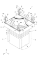
- FIG. 1 is a perspective view showing an example of a transport system according to an embodiment.
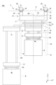
- 2 is a perspective view showing an example of the carriage of FIG. 1.
- FIG. 3 is a side view showing an example of the truck of FIG. 1.
- FIG. 4 is a block diagram showing the transport system of FIG. 1;
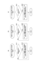
- FIG. 5(a) is a flow chart showing thinning processing of the carriages during transfer.
- FIG. 5(b) is a flow chart showing the process of thinning out carts during charging.
- FIG. 5(c) is a flow chart showing the process of thinning out vehicles during turns.
- FIG. 6(a) is a flow chart showing the process of thinning out vehicles waiting for transfer.
- FIG. 6(b) is a flow chart showing the thinning processing of vehicles waiting for blocking.
- FIG. 6(c) is a flow chart showing the process of thinning out vehicles waiting to enter the area.
- FIG. 7(a) is a flow chart showing the process of thinning out the vehicles under maintenance.
- FIG. 7(b) is a flow chart showing the process of thinning out trucks that are stopped due to an error.
- FIG. 7(c) is a flow chart showing the process of thinning out idling-stop trucks.
- FIG. 1 is a perspective view showing an example of the transport system SYS according to the embodiment.
- 2 is a perspective view of a carriage V used in the transport system SYS of FIG. 1.
- FIG. 3 is a side view showing the truck V of FIG. 2.
- FIG. 4 is a block diagram showing the transport system SYS of FIG.
- the scale is appropriately changed.
- one direction along the horizontal plane is defined as the X direction
- a direction orthogonal to the X direction and along the horizontal plane is defined as the Y direction
- a vertical direction is defined as the Z direction.
- the transportation system SYS is, for example, a grid system for transporting articles M by means of carts V in a clean room of a semiconductor manufacturing factory.
- the conveying system SYS includes a first truck V1 to an n-th truck Vn (hereinafter collectively referred to as “truck V”) (see FIG. 4), a system controller 5 for controlling a plurality of trucks V, and a plurality of trucks V running. and a rail R for In this embodiment, an example in which the trolley V is an overhead trolley will be described.
- the carriage V moves along the rails R of the transport system SYS.
- a rail R is a running path for the carriage V. As shown in FIG.
- the carriage V moves along the rails R of the transport system SYS and transports an article M such as a FOUP containing semiconductor wafers or a reticle Pod containing a reticle.
- the carriage V may be referred to as a carriage, a carriage, a traveling carriage, or a traveling vehicle.
- the rail R is laid on or near the ceiling of a building such as a clean room.
- the rail R is provided adjacent to, for example, a processing device, a stocker (automated warehouse), or the like.
- the processing apparatus is, for example, an exposure apparatus, a coater developer, a film forming apparatus, an etching apparatus, etc., and performs various types of processing on the semiconductor wafers in the articles M conveyed by the carriage V.
- the stocker stores the articles M conveyed by the truck V.
- Rail R is an example of a track configuration.
- the rail R is a grid track arranged in a grid pattern in a plan view.
- the rail R is a suspended rail that extends along the horizontal direction.
- the rail R is a grid rail having a plurality of first rails R1, a plurality of second rails R2, and a plurality of intersections R3.
- the plurality of first rails R1 each extend along the X direction.
- the multiple second rails R2 each extend along the Y direction.
- the rail R is formed in a grid pattern in plan view by a plurality of first rails R1 and a plurality of second rails R2.
- the rail R forms a plurality of squares with a plurality of first rails R1 and a plurality of second rails R2.
- the intersection R3 is arranged at a portion corresponding to the intersection of the first rail R1 and the second rail R2.
- the intersection R3 is adjacent to the first rail R1 in the X direction and adjacent to the second rail R2 in the Y direction.
- the intersection R3 is a connection track for connecting the first rail R1 and the second rail R2, connecting the first rails R1 to each other, and connecting the second rails R2 to each other.
- the intersection R3 is formed when the truck V travels along the first rail R1, when the truck V travels along the second rail R2, and when the truck V travels from the first rail R1 to the second rail R2 or the second rail R2. This track is used both when traveling from the rail R2 to the first rail R1.
- the rails R are provided in a direction in which the plurality of first rails R1 and the plurality of second rails R2 are orthogonal, so that the plurality of grid cells 2 are adjacent to each other in plan view.
- One grid cell 2 corresponds to one square and is surrounded by two first rails R1 adjacent in the Y direction and two second rails R2 adjacent in the X direction in plan view. is a rectangular area.
- FIG. 1 shows a part of the rail R, and the rail R has the same configuration continuously formed in the X direction and the Y direction from the illustrated configuration.
- the first rail R1, the second rail R2, and the intersection R3 are suspended from the ceiling (not shown) by suspension members H (see FIG. 1).
- the suspension member H includes a first portion H1 for suspending the first rail R1, a second portion H2 for suspending the second rail R2, a third portion H3 for suspending the intersection R3, have The first portion H1 and the second portion H2 are provided at two locations across the third portion H3.
- the first rail R1, the second rail R2, and the intersection R3 respectively have running surfaces R1a, R2a, and R3a on which running wheels 21 of the truck V run, which will be described later.
- a gap is formed between the first rail R1 and the intersection R3 and between the second rail R2 and the intersection R3.
- the gaps between the first rail R1 and the intersection R3 and between the second rail R2 and the intersection R3 are set when the truck V travels on the first rail R1 and traverses the second rail R2, or when the truck V runs on the first rail R1 and crosses the second rail R2. This is a portion through which a connecting portion 30, which is a part of the carriage V and will be described later, passes when traveling on the second rail R2 and crossing the first rail R1.
- the gaps between the first rail R1 and the crossing portion R3 and between the second rail R2 and the crossing portion R3 are provided with widths that allow the connecting portion 30 to pass therethrough.
- the first rail R1, the second rail R2, and the intersection R3 are provided along the same horizontal plane.
- the transport system SYS includes a communication system (not shown).
- a communication system is used for communication between the truck V and the system controller 5 .
- the carriage V and the system controller 5 are communicably connected via a communication system.
- the truck V has a main body portion 10 , a traveling portion 20 , a connecting portion 30 and a truck controller 50 .
- the body part 10 is arranged below the rail R.
- the body portion 10 is formed in, for example, a rectangular shape in plan view.
- the body portion 10 is formed to have a size that can be accommodated in one grid cell 2 (see FIG. 1) of the rail R in plan view. For this reason, a space is secured for passing other trucks V running on the adjacent first rail R1 or second rail R2.
- the body portion 10 includes an upper unit 17 and a transfer device 18 .
- the upper unit 17 is suspended from the traveling section 20 via the connecting section 30 .
- the upper unit 17 has, for example, a rectangular shape in plan view, and has four corners on the upper surface 17a.
- the body part 10 has running wheels 21, connecting parts 30, and direction changing mechanisms 34 at each of the four corner parts.
- the main body 10 can be stably suspended by the running wheels 21 arranged at the four corners of the main body 10, and the main body 10 can be stably run.
- the transfer device 18 moves along the horizontal direction with respect to the traveling section 20 to transfer the article to and from the load port (mounting table).
- the transfer device 18 is provided below the upper unit 17 .
- the transfer device 18 is rotatable around a rotation axis AX1 in the Z direction.
- the transfer device 18 includes an article holding portion 13 that holds the article M below the rail R, an elevation driving portion 14 that vertically moves the article holding portion 13 up and down, and a horizontal sliding movement of the elevation driving portion 14. It has a lateral extension mechanism 11 and a rotating portion 12 that holds the lateral extension mechanism 11 .
- the load port is a transfer destination or a transfer source of the truck V, and is a point at which the article M is transferred to and from the truck V.
- the article holding section 13 holds the article M by hanging it by gripping the flange section Ma of the article M.
- the article holding portion 13 is, for example, a chuck having a horizontally movable claw portion 13a. Hold M.
- the article holding portion 13 is connected to a hanging member 13b such as a wire or belt.
- the elevation driving unit 14 is, for example, a hoist, and lowers the article holding unit 13 by drawing out the hanging member 13b, and raises the article holding unit 13 by winding the hanging member 13b.
- the elevation driving unit 14 is controlled by the carriage controller 50 to lower or raise the article holding unit 13 at a predetermined speed.
- the elevation driving section 14 is controlled by the carriage controller 50 to hold the article holding section 13 at the target height.
- the lateral pushing mechanism 11 has, for example, a plurality of movable plates stacked in the Z direction.
- a lifting drive unit 14 is attached to the lowermost movable plate.
- the movable plate moves in a direction perpendicular to the traveling direction of the carriage V in the horizontal plane, and the lifting drive section 14 and the article holding section 13 attached to the lowermost movable plate move in the traveling direction of the carriage V. Slide out (slide) in a right angle direction.
- the rotating part 12 is provided between the lateral extension mechanism 11 and the upper unit 17 .
- the rotating portion 12 has a rotating member 12a and a rotating driving portion 12b.
- the rotating member 12a is provided so as to be rotatable around the axis in the Z direction.
- the rotating member 12 a supports the lateral extension mechanism 11 .
- the rotation drive unit 12b uses, for example, an electric motor, and rotates the rotation member 12a in the direction around the rotation axis AX1.
- the rotating portion 12 rotates the rotating member 12a by the driving force from the rotating driving portion 12b, and rotates the lateral ejection mechanism 11 (elevating driving portion 14 and article holding portion 13) in the direction around the rotation axis AX1.
- the transfer device 18 can transfer the article M to the load port.
- the truck V may be provided with a cover W.
- the cover W surrounds the transfer device 18 and the article M held by the transfer device 18 .
- the cover W has a cylindrical shape with an open lower end, and has a shape in which a portion from which the movable plate of the lateral pushing mechanism 11 protrudes is cut away.
- the upper end of the cover W is attached to the rotating member 12a of the rotating portion 12, and rotates around the rotation axis AX1 as the rotating member 12a rotates.
- the running unit 20 has running wheels 21 and auxiliary wheels 22 .
- the traveling wheels 21 are arranged at four corners of the upper surface 17a of the upper unit 17 (main body 10). Each of the running wheels 21 is attached to an axle provided in the connecting portion 30 .
- Each of the traveling wheels 21 is rotationally driven by the driving force of the traveling drive section 33 .
- Each traveling wheel 21 rolls on the rail R.
- Each of the traveling wheels 21 rolls on the first rail R1, the second rail R2, and the traveling surfaces R1a, R2a, and R3a of the intersection R3, thereby causing the truck V to travel. It should be noted that not all of the four running wheels 21 are rotationally driven by the driving force of the running drive unit 33, and some of the four running wheels 21 may be rotationally driven.
- the traveling wheels 21 are provided so as to be able to turn in the ⁇ Z direction around the turning axis AX2.
- the traveling wheels 21 are turned in the ⁇ Z direction by a direction changing mechanism 34, which will be described later, and as a result, the traveling direction of the carriage V can be changed.
- the auxiliary wheels 22 are arranged one by one on the front and rear sides of the running wheels 21 in the running direction.
- Each of the auxiliary wheels 22 is rotatable about parallel or substantially parallel axles along the XY plane, similarly to the traveling wheels 21 .
- the lower ends of the auxiliary wheels 22 are set higher than the lower ends of the running wheels 21 .
- the auxiliary wheels 22 do not contact the running surfaces R1a, R2a and R3a. Further, when the traveling wheels 21 pass through the gaps between the first rail R1 and the intersection R3 and between the second rail R2 and the intersection R3, the auxiliary wheels 22 move along the traveling surfaces R1a, R2a, It contacts with R3a and suppresses the drop of the running wheel 21. - ⁇ In addition, it is not limited to providing two auxiliary wheels 22 for one traveling wheel 21. For example, one auxiliary wheel 22 may be provided for one traveling wheel 21, or the auxiliary wheel 22 may not be provided. good too.
- the connecting portion 30 connects the upper unit 17 of the main body portion 10 and the traveling portion 20 .
- the connecting portions 30 are provided at four corner portions of the upper surface 17a of the upper unit 17 (main body portion 10).
- the connecting portion 30 suspends the body portion 10 from the traveling portion 20 and is arranged below the rail R.
- the connection part 30 has a support member 31 and a connection member 32 .
- the support member 31 rotatably supports the rotating shaft of the traveling wheels 21 and the rotating shaft of the auxiliary wheels 22 .
- the support member 31 holds the relative positions of the traveling wheels 21 and the auxiliary wheels 22 .
- the support member 31 is formed in a plate shape, for example, and is formed to have a thickness that allows it to pass through the gaps between the first rail R1 and the crossing portion R3 and between the second rail R2 and the crossing portion R3.
- connection member 32 extends downward from the support member 31 and is connected to the upper surface 17a of the upper unit 17 to hold the upper unit 17.
- the connection member 32 includes therein a transmission mechanism for transmitting the driving force of the travel drive unit 33 to be described later to the travel wheels 21 .
- This transmission mechanism may be configured using a chain or belt, or may be configured using a gear train.
- the connection member 32 is provided so as to be rotatable in the ⁇ Z direction around the rotation axis AX2. By turning the connecting member 32 about the turning axis AX2, the traveling wheels 21 can be turned in the ⁇ Z direction about the turning axis AX2 via the support member 31.
- a travel drive unit 33 and a direction change mechanism 34 are provided in the connection unit 30 (see FIG. 2).
- the travel drive unit 33 is attached to the connection member 32 .
- the travel drive unit 33 is a drive source that drives the travel wheels 21, and uses, for example, an electric motor.
- the four running wheels 21 are drive wheels driven by the running drive unit 33 respectively.
- the four running wheels 21 are controlled by the truck controller 50 so as to have the same number of revolutions.
- the direction changing mechanism 34 turns the connecting member 32 of the connecting portion 30 around the turning axis AX2, thereby turning the running wheels 21 in the ⁇ Z direction around the turning axis AX2.
- the truck V is turned (from the first state in which the traveling direction is the X direction to the second state in which the traveling direction is the Y direction, or the traveling direction is the Y direction). (switching from the second state to the first state in which the traveling direction is the X direction).
- the running wheels 21 and the auxiliary wheels 22 arranged at the four corners of the upper surface 17a each turn in the ⁇ Z direction within a range of 90 degrees around the turning axis AX2.
- Driving of the turning mechanism 34 is controlled by the carriage controller 50 .
- the running wheels 21 and the auxiliary wheels 22 By turning the running wheels 21 and the auxiliary wheels 22, the running wheels 21 shift from contacting one of the first rail R1 and the second rail R2 to contacting the other. Therefore, it is possible to switch between the first state in which the traveling direction of the truck V is in the X direction and the second state in which the traveling direction is in the Y direction, that is, the truck V can turn.
- the carriage V stops running.
- the travel stop is, for example, a state in which the article M to be conveyed is not moving.
- the carriage V includes a position detection unit 38 that detects position information (see FIG. 4).
- the position detection unit 38 detects the current position of the truck V by detecting a position marker (not shown) indicating position information.
- the position detection unit 38 detects the position marker in a non-contact manner.
- a position marker is installed for each grid cell 2 of the rail R. As shown in FIG.
- the truck controller 50 comprehensively controls the truck V.
- the truck controller 50 is a computer including a CPU (Central Processing Unit), ROM (Read Only Memory), RAM (Random Access Memory), and the like.
- the truck controller 50 can be configured as software in which, for example, a program stored in a ROM is loaded onto a RAM and executed by a CPU.
- the carriage controller 50 may be configured as hardware such as an electronic circuit.
- the carriage controller 50 may be composed of one device, or may be composed of a plurality of devices. When a plurality of devices are configured, they are connected via a communication network such as the Internet or an intranet to logically construct one truck controller 50 .
- the carriage controller 50 is provided in the main body 10 in this embodiment (see FIG. 3), it may be provided outside the main body 10 .
- the truck controller 50 controls the traveling of the truck V based on the transport command.
- the truck controller 50 controls the traveling of the truck V by controlling the traveling drive unit 33, the direction changing mechanism 34, and the like.
- the carriage controller 50 controls, for example, the running speed, the operation for stopping, and the operation for turning.
- the truck controller 50 controls the traveling of the truck V so that it does not enter the travel area, blocking area, and transfer area where more than a specified number of trucks V exist (details described later).
- the carriage controller 50 controls the transfer operation of the carriage V based on the transport command.
- the truck controller 50 controls the transfer operation of the truck V by controlling the transfer device 18 and the like.
- the carriage controller 50 controls the operation of grabbing an article M placed at a predetermined load port and the operation of unloading the held article M to a predetermined load port.
- Carriage controller 50 periodically generates and updates state information (not shown). State information is stored in the storage unit 51 .
- the truck controller 50 transmits status information to the system controller 5 .
- the state information includes, for example, information on the current position of the truck V, information indicating the current state of the truck V such as normal or abnormal, charge amount of the truck V, execution status (executing state) of various commands such as transport commands by the truck V. , run completed, run failed).
- the cart controller 50 transmits a blocking control request to the system controller 5 when the article M is transferred.
- the system controller 5 is a computer comprising a CPU, ROM, RAM, and the like.
- the system controller 5 can be configured, for example, as software in which a program stored in the ROM is loaded onto the RAM and executed by the CPU.
- the system controller 5 may be configured as hardware such as an electronic circuit.
- the system controller 5 may be composed of one device, or may be composed of a plurality of devices. When a plurality of devices are configured, they are connected via a communication network such as the Internet or an intranet to logically construct one system controller 5 .
- Various controls of the system controller 5 may be executed at least in part by the truck controller 50 .
- the system controller 5 selects one of a plurality of carriages V capable of transporting the article M, and assigns a transport command to the selected carriage V.
- the transport command includes a travel command for causing the carriage V to travel to the load port, and a command to pick up the articles M placed at the load port or unload the held articles M to the load port. .
- the system controller 5 performs blocking control, which is an exclusive control that prohibits vehicles V other than the vehicle V from entering a blocking area (predetermined area) through which the vehicle V passes.
- blocking control is an exclusive control that prohibits vehicles V other than the vehicle V from entering a blocking area (predetermined area) through which the vehicle V passes.
- the trucks V other than the truck V are controlled so as not to enter the blocking area for which occupation permission is not given, and for example, stop running before the blocking area and wait.
- the system controller 5 starts blocking control, for example, in response to a request for blocking control from the truck controller 50 of the truck V, and gives permission for the truck V to occupy the blocking area.
- the blocking area is divided by two grid cells corresponding to the squares of the rail R.
- the blocking area may be a predetermined area into which the vehicle V enters after the vehicle V turns (changes direction).
- the system controller 5 prevents other carriages V from entering a transfer area required for the transfer.
- Blocking control for transfer which is prohibited exclusive control, is performed.
- the movement of the other truck V is controlled so as not to enter the transfer area required for the transfer of the truck V, and stops before the transfer area and waits.
- the system controller 5 prohibits other trucks V from entering the transfer area of the truck V based on a transport command assigned to the truck V, for example.
- the area for transfer corresponds to the area occupied by the carriage V when the article M is transferred in plan view.
- the transfer area is partitioned in units of two grid cells corresponding to the squares of the rail R.
- the system controller 5 performs area number limit control to prohibit entry into a travel area when the number of trolleys V present in one of the travel areas is greater than or equal to a specified number. As a result, the carriage V is controlled so as not to enter a travel area in which more than the specified number of carriages V exist. As a result, for example, a truck V that is about to enter a travel area in which more than a specified number of trucks V are present stops running in front of the travel area and waits.
- the system controller 5 can determine whether or not the number of trucks V present in the travel area is equal to or greater than a specified number, based on current position information included in the state information of the plurality of trucks V, for example.
- the travel area is an area in which the truck V can travel and includes the rails R.
- a plurality of travel areas are set.
- the specified number is not particularly limited, and may be a predetermined number.
- the travel area is one of a plurality of areas obtained by dividing the entire area in which the carriage V can travel.
- the system controller 5 transmits a filling execution command, which is a command for charging the trolley V, to the trolley V when the trolley V needs to be charged.
- the charging execution command causes the vehicle V to stop running.
- the determination of whether or not charging of the truck V is necessary can be made based on the state information of the truck V.
- FIG. Further, when performing maintenance on the truck V, the system controller 5 transmits to the truck V a maintenance mode execution command, which is a command to execute the maintenance mode.
- the maintenance mode is a mode for performing maintenance on the trolley V.
- FIG. In the maintenance mode the truck V is driven at low speed or stopped. Maintenance is not particularly limited and includes various types of maintenance.
- the maintenance mode may be a mode in which the truck V is remotely driven according to the user's operation.
- the system controller 5 When an error occurs in the truck V, the system controller 5 sends to the truck V an error stop command, which is a command to stop the truck V in error. Whether or not an error has occurred in the truck V can be determined based on the state information of the truck V. FIG. Further, when stopping the vehicle V in the idling state, the system controller 5 transmits to the vehicle V an idling stop command, which is a command to stop the vehicle V in the idling state.
- the idling state is a state in which the bogie V that is not running maintains a state in which it can immediately respond to the start of running.
- the system controller 5 of the present embodiment executes periodic communication (hereinafter also referred to as "polling communication") for sequentially and periodically communicating with a plurality of trucks V.
- polling communication a plurality of carriages V existing within the control target range of the system controller 5 are the objects of communication, and communication is sequentially performed with respect to some or all of the plurality of carriages V one by one. communication to be repeated.
- the system controller 5 stops communication with the truck V in polling communication, or stops communication with the truck V in polling communication. Execute polling thinning processing to reduce the frequency of communication.
- the predetermined operating state of the truck V targeted for the polling thinning process has a first operating state in which the truck V stops running and performs an operation other than running.
- the system controller 5 suspends communication with the vehicle V in the first operating state in polling communication for a period based on the time required for the operation in the first operating state.
- the first operation state includes a transfer-in-progress state, which is a state from the start of the transfer of the article M to the point immediately before the end of the transfer of the article M by the carriage V that is not traveling. That is, in the polling thinning process, the thinning process for the carriages during transfer shown in FIG. 5(a) is periodically and repeatedly executed.
- step S11 it is determined whether or not there is a carriage V during transfer that is in the state of being transferred among the plurality of carriages V to be polled (step S11). For example, the determination of whether or not the truck V is the truck during transfer may be made based on the state information of the truck V. FIG. For example, the determination as to whether or not the carriage V is the carriage during transfer may be made based on a transport command assigned to the carriage V by the system controller 5 . For example, the determination of whether or not the truck V is the truck during transfer may be made based on information or instructions from a host controller (not shown).
- the status information of the carriage V may include information regarding the transfer time of the carriage V (transfer start timing, end timing, and period required for transfer) according to the load port to be transferred.
- step S11 the process of this cycle ends, and the process proceeds to step S11 of the next cycle.
- step S12 the communication with the transfer vehicle in polling communication is stopped (step S12).
- step S12 the carriages that are being transferred are thinned out from the plurality of carriages V that are targets of polling communication.
- step S12 communication is performed sequentially and periodically with a plurality of carriages V other than the carriage during transfer.
- the first operating state includes the charging state, which is the state from when the carriage V, which is not traveling, starts charging until just before it ends. That is, in the polling thinning process, the thinning process of the charging vehicle shown in FIG. 5B is periodically and repeatedly executed.
- step S21 it is determined whether or not there is a charging carriage V that is in a charging state among the plurality of carriages V targeted for polling communication (step S21).
- the determination as to whether or not the vehicle V is the vehicle being filled may be made based on the state information of the vehicle V.
- the determination as to whether or not the vehicle V is the vehicle being filled may be made based on the filling execution command sent to the vehicle V by the system controller 5 .
- the determination of whether or not the vehicle V is the vehicle being filled may be made based on information or instructions from a host controller (not shown).
- the status information of the vehicle V may include information regarding the start timing of filling of the vehicle V, the end timing of filling, and the period (for example, 5 minutes) required for filling.
- step S21 If NO in step S21, the process of this cycle ends, and the process proceeds to step S21 of the next cycle.
- step S22 communication with the vehicle being charged in polling communication is stopped.
- step S22 the carts being charged are thinned out from the plurality of carts V to be polled.
- step S22 communication is performed sequentially and periodically with a plurality of carriages V other than the carriage being charged.
- the truck V requests blocking control to prohibit other trucks V from entering a predetermined area (blocking area) into which the truck V enters after the turn.
- a predetermined area blocking area
- Including the state during the turn which is the state up until just before the timing to be performed. That is, in the polling thinning process, the thinning process for the mid-turn trucks shown in FIG. 5(c) is periodically and repeatedly executed.
- the request timing for this blocking control may be before the turn operation is completed, thereby eliminating time loss. Also, the request timing for this blocking control may be after the turn operation is completed.
- step S31 it is determined whether or not there is a vehicle V during a turn, which is a vehicle V in a turning state, among the plurality of vehicles V targeted for polling communication (step S31).
- the determination as to whether or not the vehicle V is a vehicle during a turn may be made based on the state information of the vehicle V.
- FIG. the determination as to whether or not the truck V is an in-turn truck may be made based on a transport command assigned to the truck V by the system controller 5 .
- the determination as to whether or not the vehicle V is a vehicle during a turn may be made based on information or instructions from a host controller (not shown).
- the state information of the vehicle V may include information regarding the start timing of the turn of the vehicle V, the end timing of the turn, the period required for the turn, the request timing of the blocking control of the vehicle V, and the like.
- step S31 If NO in step S31, the process of this cycle ends, and the process proceeds to step S31 of the next cycle.
- step S32 communication with the vehicle during the turn in polling communication is stopped (step S32).
- step S32 the vehicles V during the turn are thinned out from the plurality of vehicles V to be polled.
- communication is performed sequentially and periodically with a plurality of trucks V other than the truck during the turn.
- the predetermined operation state of the truck V to be the target of the polling thinning process has a second operation state in which the truck V stops running due to the influence of the operation of the other truck V.
- the system controller 5 stops communication with the truck V in the second operation state in the polling communication while the influence of the operation of the other truck V is occurring or until just before the influence disappears.
- the carriage V for which communication is to be stopped is also referred to as "own carriage V".
- the second operating state includes a transfer waiting state in which the own cart V stops traveling from the time when the other cart V starts the transfer of the article until immediately before it ends. That is, in the polling thinning process, the thinning process of the transfer waiting vehicles shown in FIG. 6A is periodically and repeatedly executed.
- step S41 it is determined whether or not there is a carriage waiting for transfer, which is the own carriage V waiting for transfer, among the plurality of carriages V to be polled (step S41).
- the determination as to whether or not the own vehicle V is a transfer waiting vehicle may be made based on the state information of the own vehicle V and the other vehicles V.
- the determination as to whether or not the own vehicle V is a transfer waiting vehicle may be made based on a transfer blocking control command.
- the determination as to whether or not the own vehicle V is a transfer waiting vehicle may be made based on information or instructions from a host controller (not shown).
- the state information of the own truck V and the other truck V includes the start timing of the transfer of the other truck V, the end timing of the transfer of the other truck V, the time required for the transfer of the other truck V, and the own truck V. It may include the start timing of stopping the running of V, the end timing of stopping the running of the vehicle V, and the like.
- step S41 If NO in step S41, the process of this cycle ends, and the process proceeds to step S41 of the next cycle.
- step S42 communication with the transfer waiting vehicle in polling communication is stopped.
- step S42 the carriages waiting for transfer are thinned out from the plurality of carriages V to be polled.
- step S42 communication is performed sequentially and periodically with a plurality of carriages V other than the carriages waiting for transfer.
- the second operation state is a control requested by other trucks V, and is a state from when the own truck V starts to stop running to immediately before it ends in accordance with the blocking control of the trucks V other than the other trucks V.
- Blocking Including wait states. That is, in the polling thinning process, the thinning process of the vehicles waiting for blocking shown in FIG. 6B is periodically and repeatedly executed.
- step S51 it is determined whether or not there is a vehicle V waiting for blocking, which is the own vehicle V waiting for blocking, among the multiple vehicles V targeted for polling communication (step S51).
- the determination as to whether or not the own vehicle V is a vehicle waiting for blocking may be made based on the state information of the own vehicle V and other vehicles V.
- FIG. the determination as to whether or not the own vehicle V is a vehicle waiting for blocking may be made based on a command relating to blocking control.
- the determination as to whether or not the own vehicle V is a vehicle waiting for blocking may be made based on a command from a host controller (not shown).
- the state information of the vehicle V and the other vehicle V may include whether or not the other vehicle V requests blocking control, the start timing and end timing of stopping the vehicle V, and the like.
- step S51 If NO in step S51, the process of this cycle ends, and the process proceeds to step S51 of the next cycle.
- step S52 communication with the blocking waiting vehicle in polling communication is stopped.
- step S52 communication with the carriages waiting for blocking are thinned out from the plurality of carriages V to be polled.
- step S52 communication is performed sequentially and periodically with a plurality of carriages V other than the carriages waiting for blocking.
- the own truck V stops traveling according to the area number limit control that prohibits entry into that traveling area.
- step S51 it is determined whether or not there is a vehicle V waiting to enter the area, which is the vehicle V waiting to enter the area, among the multiple vehicles V to be polled (step S51).
- the determination as to whether or not the own vehicle V is a vehicle waiting to enter the area may be made based on the state information of the own vehicle V and the other vehicles V.
- FIG. the determination as to whether or not the own vehicle V is a vehicle waiting to enter an area may be made based on a command relating to area number limit control.
- the determination as to whether or not the own vehicle V is a vehicle waiting to enter an area may be made based on a command from a host controller (not shown).
- the status information of the own truck V and the other trucks V may include information on the presence or absence of area number limit control, information on the current position of the own truck V, information on the current positions of the other trucks V, and the like.
- step S61 If NO in step S61, the process of this cycle ends, and the process proceeds to step S61 of the next cycle.
- step S62 communication with the vehicle waiting to enter the area in polling communication is stopped.
- step S62 the vehicles waiting to enter the area are thinned out from the plurality of vehicles V to be polled.
- step S62 communication is performed sequentially and periodically with a plurality of carriages V other than the carriages waiting to enter the area.
- the predetermined operation state of the truck V to be the target of the polling thinning process has a third operation state in which the truck V is executing the set operation indefinitely.
- the system controller 5 reduces the frequency of communication with the truck V in the third operating state in polling communication.
- the third operating state includes a maintenance state in which the vehicle V is in maintenance mode. That is, in the polling thinning process, the thinning process for the carriages under maintenance shown in FIG. 7A is periodically and repeatedly executed.
- step S71 it is determined whether or not there is a carriage V in maintenance state among the plurality of carriages V targeted for polling communication (step S71). For example, the determination as to whether or not the vehicle V is a vehicle under maintenance may be made based on the state information of the vehicle V. For example, the determination as to whether or not the vehicle V is under maintenance may be made based on a maintenance mode execution command transmitted by the system controller 5 . For example, the determination as to whether or not the vehicle V is under maintenance may be made based on a command from a host controller (not shown).
- the status information of the trolley V may include information as to whether the trolley V is executing the maintenance mode or not.
- step S71 the process of this cycle ends, and the process proceeds to step S71 of the next cycle.
- step S72 the frequency of communication with the vehicle under maintenance in polling communication is reduced.
- step S72 the vehicles under maintenance are thinned out from the plurality of vehicles V to be polled so that the frequency of communication with the vehicles under maintenance is low.
- step S72 communication with a plurality of trucks V is performed sequentially and periodically while the frequency of communication with the truck under maintenance is reduced.
- step S72 the frequency of communication with the vehicle under maintenance is reduced so as to communicate with the vehicle under maintenance once every five seconds in polling communication.
- the third operating state includes an error stopping state in which the truck V is stopped due to an error. That is, in the polling thinning process, the thinning process for the error-stopped truck shown in FIG. 7B is periodically and repeatedly executed.
- step S81 it is determined whether or not there is an error-stopping truck V in error-stopping state among the plurality of trucks V to be polled (step S81).
- the determination of whether or not the truck V is an error-stopping truck may be made based on the state information of the truck V.
- FIG. the determination as to whether or not the vehicle V is an error-stopped vehicle may be made based on an error stop command transmitted by the system controller 5 .
- the determination as to whether or not the vehicle V is an error-stopped vehicle may be made based on a command from a host controller (not shown).
- the state information of the truck V may include information such as whether the state of the truck V is abnormal and whether the truck V is stopping.
- step S81 the frequency of communication with the error-stopped truck in polling communication is reduced (step S82).
- step S82 the error-stopping vehicles are thinned out from the plurality of vehicles V to be polled so that the frequency of communication with the error-stopping vehicles becomes low.
- step S82 communication with the plurality of trucks V is performed sequentially and periodically while the frequency of communication with the truck during error stop is lowered.
- step S82 the frequency of communication with the error-stopping truck is reduced so that communication with the error-stopping truck is performed once every 10 seconds in polling communication.
- the third operating state includes an idling stop state in which the bogie is in an idling state and is stopped. That is, in the polling thinning-out process, the thinning-out process for the idling stopped vehicles shown in FIG. 7(c) is periodically and repeatedly executed.
- the determination as to whether or not the truck V is an idling stop truck may be made based on the state information of the truck V.
- the determination as to whether or not the vehicle V is an idling stop vehicle may be made based on an idling stop command transmitted by the system controller 5 .
- the determination as to whether the truck V is an idling stop truck may be made based on a command from a host controller (not shown).
- the state information of the truck V may include information such as whether the truck V is in the idling state and whether the truck V is stopping.
- step S92 the frequency of communication with the idling stop vehicle in polling communication is reduced (step S92).
- step S92 the non-idling trucks are thinned out from among the plurality of trucks V to be polled so that the frequency of communication with the non-idling trucks is low.
- step S92 communication with the plurality of trucks V is performed sequentially and periodically while the frequency of communication with the truck during idling stop is lowered.
- step S92 the frequency of communication with the idling stop truck is reduced so that communication with the idling stop truck is performed once every five seconds in polling communication.
- the predetermined operating state includes a first operating state in which the carriage V stops running and performs an operation other than running. In this case, it is possible to reduce the time required for communication with the truck V in the first operating state in polling communication.
- the first operating state includes the state of being transferred. In this case, it is possible to reduce the time required for communication with the carriage during transfer in polling communication.
- the first operating state includes a charging state. In this case, it is possible to reduce the time required for communication with the charging vehicle in polling communication.
- the first operating state includes a turning state. In this case, it is possible to reduce the time required for communication with the vehicle during the turn in polling communication.
- the predetermined operating state has a second operating state in which the carriage V is stopped due to the movement of another carriage V. In this case, it is possible to reduce the time required for communication with the truck V in the second operation state in polling communication.
- the second operating state includes a transfer waiting state. In this case, it is possible to reduce the time required for communication with the transfer waiting vehicle in polling communication.
- the second operating state includes a wait-for-blocking state. In this case, it is possible to reduce the time required for communication with the blocking waiting vehicle in polling communication.
- the second operation state includes an area entry waiting state. In this case, it is possible to reduce the time required for communication with the vehicle waiting to enter the area in polling communication.
- the predetermined operating state has a third operating state in which the carriage V is performing a set action indefinitely. In this case, it is possible to reduce the time required for communication with the truck V in the third operation state in polling communication.
- the frequency of communication with the carriage V in the third operating state in polling communication is reduced.
- polling communication it is possible to increase the frequency of reducing the time required for communication with the truck V in the third operation state.
- the communication with the truck V in the third operation state in the polling communication is not stopped, the communication with the truck V can be maintained. It is effective in restoring from the normal operation state.
- the third operating state includes a state under maintenance. In this case, it is possible to reduce the time required for communication with the vehicle under maintenance in polling communication.
- the third operation state includes an error stopping state. In this case, it is possible to reduce the time required for communication with the vehicle during error stop in polling communication.
- the third operating state includes an idling stop state. In this case, it is possible to reduce the time required for communication with the idling stop truck in polling communication.
- the transport system SYS is equipped with rails R on which a plurality of carriages V run, and constitutes a so-called grid system. This makes it easier to freely select the traveling route of the carriage V, suppresses the occurrence of traffic jams, and makes it possible to improve the transportation efficiency.
- polling thinning processing is being executed in polling communication can be confirmed based on the log of the system controller 5, for example.
- the execution and stop of the polling thinning process may be selected by, for example, a user's operation input via the operation input unit, and the execution and stop of the polling thinning process may be controlled according to the selection result.
- the predetermined operating state is not particularly limited.
- the predetermined operating state may include at least one of the first operating state, the second operating state, and the third operating state, or may include other operating states.
- the information used for determining whether the truck V is in a predetermined operating state is not particularly limited, and various information may be used.
- the first operating state is not particularly limited.
- the first operating state may include at least one of a loading state, a charging state, and a turning state, and may further include other states.
- the second operating state is not particularly limited.
- the second operation state may include at least one of a loading wait state, a blocking wait state, and an area entry wait state, and may further include other states.
- the third operating state is not particularly limited.
- the third operation state may include at least one of a maintenance state, an error stop state, and an idling stop state, and may further include other states.
- a grid system is used as the transport system SYS, but the transport system SYS is not limited to the grid system.
- an AGV Automated Guided Vehicle
- various known systems that run on a grid-shaped travel path may be employed.
- the carriage V holds the article M below the rail R in the above embodiment, the main body 10 may be arranged above the rail R to hold the article M above the rail R.
Landscapes
- Engineering & Computer Science (AREA)
- Aviation & Aerospace Engineering (AREA)
- Radar, Positioning & Navigation (AREA)
- Remote Sensing (AREA)
- Physics & Mathematics (AREA)
- General Physics & Mathematics (AREA)
- Automation & Control Theory (AREA)
- Mechanical Engineering (AREA)
- Control Of Position, Course, Altitude, Or Attitude Of Moving Bodies (AREA)
- Warehouses Or Storage Devices (AREA)
- Control Of Conveyors (AREA)
Abstract
Description
1サイクル時間=t・N
t:1台の台車当たりの応答時間、N:ポーリング通信の対象となる台車の数
Claims (17)
- 複数の台車と、複数の前記台車を制御するコントローラと、を備えた搬送システムであって、
前記コントローラは、複数の前記台車との間で順次に且つ周期的に通信する周期的通信を行い、
複数の前記台車の少なくとも何れかが所定の動作状態である場合に、前記周期的通信における当該台車との間の通信を停止する、又は、前記周期的通信における当該台車との間の通信の頻度を低くする、搬送システム。 - 前記所定の動作状態は、前記台車が走行停止して走行以外の動作を実行している第1動作状態を有する、請求項1に記載の搬送システム。
- 前記周期的通信における前記第1動作状態の前記台車との間の通信を、前記第1動作状態の動作に要する時間に基づく期間、停止する、請求項2に記載の搬送システム。
- 前記第1動作状態は、前記台車が物品の移載を開始してから終了する直前までの状態である移載中状態を含む、請求項2又は3に記載の搬送システム。
- 前記第1動作状態は、前記台車が充電を開始してから終了する直前までの状態である充電中状態を含む、請求項2~4の何れか一項に記載の搬送システム。
- 前記第1動作状態は、前記台車がターンを開始してから、当該台車がターン後に進入する所定領域への他の台車の進入を禁止するブロッキング制御の要求を当該台車が行うべきタイミングの直前までの状態であるターン中状態を含む、請求項2~5の何れか一項に記載の搬送システム。
- 前記所定の動作状態は、前記台車が他の台車の動作による影響で走行停止している第2動作状態を有する、請求項1~6の何れか一項に記載の搬送システム。
- 前記周期的通信における前記第2動作状態の前記台車との間の通信を、前記他の台車の動作による影響が生じている間、又は、当該影響が消失する直前まで停止する、請求項7に記載の搬送システム。
- 前記第2動作状態は、前記他の台車が物品の移載を開始してから終了する直前までにおいて前記台車が走行停止している状態である移載待ち状態を含む、請求項7又は8に記載の搬送システム。
- 前記第2動作状態は、前記他の台車が要求する制御であって前記他の台車以外の前記台車の所定領域への進入を禁止するブロッキング制御に従って、前記台車が走行停止を開始してから終了する直前までの状態であるブロッキング待ち状態を含む、請求項7~9の何れか一項に記載の搬送システム。
- 前記第2動作状態は、複数の走行エリアの何れかに存在する他の台車の台数が規定数以上の場合に当該走行エリアへの進入を禁止するエリア台数制限制御に従って、前記台車が走行停止を開始してから終了する直前までの状態であるエリア進入待ち状態を含む、請求項7~10の何れか一項に記載の搬送システム。
- 前記所定の動作状態は、前記台車が無期限に設定された動作を実行している第3動作状態を有する、請求項1~11の何れか一項に記載の搬送システム。
- 前記周期的通信における前記第3動作状態の前記台車との間の通信の頻度を低くする、請求項12に記載の搬送システム。
- 前記第3動作状態は、前記台車がメンテナンスモードを実行中の状態であるメンテナンス中状態を含む、請求項12又は13に記載の搬送システム。
- 前記第3動作状態は、前記台車がエラーにより停止中の状態であるエラー停止中状態を含む、請求項12~14の何れか一項に記載の搬送システム。
- 前記第3動作状態は、前記台車がアイドリング状態で停止中の状態であるアイドリング停止中状態を含む、請求項12~15の何れか一項に記載の搬送システム。
- 複数の前記台車が走行する格子状軌道を備える、請求項1~16の何れか一項に記載の搬送システム。
Priority Applications (6)
| Application Number | Priority Date | Filing Date | Title |
|---|---|---|---|
| US18/560,488 US20240253903A1 (en) | 2021-08-27 | 2022-01-24 | Conveyance system |
| CN202280029818.9A CN117203597A (zh) | 2021-08-27 | 2022-01-24 | 输送系统 |
| IL308536A IL308536A (en) | 2021-08-27 | 2022-01-24 | Conveyance system |
| EP22860810.5A EP4354246A4 (en) | 2021-08-27 | 2022-01-24 | CONVEYOR SYSTEM |
| JP2023543641A JP7501799B2 (ja) | 2021-08-27 | 2022-01-24 | 搬送システム |
| KR1020247009330A KR20240051991A (ko) | 2021-08-27 | 2022-01-24 | 반송 시스템 |
Applications Claiming Priority (2)
| Application Number | Priority Date | Filing Date | Title |
|---|---|---|---|
| JP2021139173 | 2021-08-27 | ||
| JP2021-139173 | 2021-08-27 |
Publications (1)
| Publication Number | Publication Date |
|---|---|
| WO2023026512A1 true WO2023026512A1 (ja) | 2023-03-02 |
Family
ID=85322578
Family Applications (1)
| Application Number | Title | Priority Date | Filing Date |
|---|---|---|---|
| PCT/JP2022/002459 Ceased WO2023026512A1 (ja) | 2021-08-27 | 2022-01-24 | 搬送システム |
Country Status (8)
| Country | Link |
|---|---|
| US (1) | US20240253903A1 (ja) |
| EP (1) | EP4354246A4 (ja) |
| JP (1) | JP7501799B2 (ja) |
| KR (1) | KR20240051991A (ja) |
| CN (1) | CN117203597A (ja) |
| IL (1) | IL308536A (ja) |
| TW (1) | TWI909084B (ja) |
| WO (1) | WO2023026512A1 (ja) |
Cited By (1)
| Publication number | Priority date | Publication date | Assignee | Title |
|---|---|---|---|---|
| JP2025014864A (ja) * | 2023-07-19 | 2025-01-30 | 株式会社ダイフク | 物品搬送設備 |
Citations (4)
| Publication number | Priority date | Publication date | Assignee | Title |
|---|---|---|---|---|
| JPH08129419A (ja) * | 1994-11-01 | 1996-05-21 | Oki Electric Ind Co Ltd | 移動体配送制御方法 |
| JP2012099033A (ja) * | 2010-11-05 | 2012-05-24 | Murata Mach Ltd | 搬送車システム |
| JP2015082574A (ja) * | 2013-10-22 | 2015-04-27 | 村田機械株式会社 | 通信デバイス及びその制御方法 |
| JP2019012500A (ja) | 2017-07-03 | 2019-01-24 | 村田機械株式会社 | 走行車システム、及び走行車システムの制御方法 |
Family Cites Families (13)
| Publication number | Priority date | Publication date | Assignee | Title |
|---|---|---|---|---|
| US4379497A (en) * | 1980-09-02 | 1983-04-12 | Bell & Howell, Company | Vehicle collision avoidance system |
| US5650703B1 (en) * | 1990-06-28 | 1999-03-02 | Hk Systems Inc | Downward compatible agv system and methods |
| JPH1196491A (ja) * | 1997-09-25 | 1999-04-09 | Meidensha Corp | 1対n通信での優先伝送方法 |
| JP4055496B2 (ja) * | 2002-07-11 | 2008-03-05 | 株式会社ダイフク | 物品搬送設備および物品搬送方法 |
| JP3991880B2 (ja) * | 2003-02-10 | 2007-10-17 | 村田機械株式会社 | 無人搬送車システム |
| KR101152813B1 (ko) * | 2009-01-23 | 2012-06-12 | 서울대학교산학협력단 | 무선 통신 시스템에서의 스케줄링 방법 |
| JP5662909B2 (ja) * | 2011-08-30 | 2015-02-04 | 株式会社Nttドコモ | ユーザ端末、及び通信方法 |
| KR102536118B1 (ko) * | 2017-12-30 | 2023-05-23 | 인텔 코포레이션 | 차량 무선 통신을 위한 방법 및 디바이스 |
| KR102077909B1 (ko) | 2018-04-27 | 2020-02-17 | (주)엔노피아 | 전기 집진 장치 |
| CN208607531U (zh) * | 2018-09-06 | 2019-03-15 | 北京东械科技有限公司 | 用于自动导引运输车的通讯装置及系统 |
| US12025989B2 (en) * | 2019-05-22 | 2024-07-02 | Murata Machinery, Ltd. | Traveling vehicle system and traveling vehicle control method |
| CN111031597A (zh) * | 2019-12-27 | 2020-04-17 | 福州聚英智能科技有限公司 | 一种agv低功耗待机通信电路及其工作方法 |
| CN111580521A (zh) * | 2020-05-17 | 2020-08-25 | 江苏源航机器人研究院有限公司 | 一种智能物流系统 |
-
2022
- 2022-01-24 EP EP22860810.5A patent/EP4354246A4/en active Pending
- 2022-01-24 US US18/560,488 patent/US20240253903A1/en active Pending
- 2022-01-24 JP JP2023543641A patent/JP7501799B2/ja active Active
- 2022-01-24 CN CN202280029818.9A patent/CN117203597A/zh active Pending
- 2022-01-24 WO PCT/JP2022/002459 patent/WO2023026512A1/ja not_active Ceased
- 2022-01-24 IL IL308536A patent/IL308536A/en unknown
- 2022-01-24 KR KR1020247009330A patent/KR20240051991A/ko active Pending
- 2022-08-19 TW TW111131246A patent/TWI909084B/zh active
Patent Citations (4)
| Publication number | Priority date | Publication date | Assignee | Title |
|---|---|---|---|---|
| JPH08129419A (ja) * | 1994-11-01 | 1996-05-21 | Oki Electric Ind Co Ltd | 移動体配送制御方法 |
| JP2012099033A (ja) * | 2010-11-05 | 2012-05-24 | Murata Mach Ltd | 搬送車システム |
| JP2015082574A (ja) * | 2013-10-22 | 2015-04-27 | 村田機械株式会社 | 通信デバイス及びその制御方法 |
| JP2019012500A (ja) | 2017-07-03 | 2019-01-24 | 村田機械株式会社 | 走行車システム、及び走行車システムの制御方法 |
Non-Patent Citations (1)
| Title |
|---|
| See also references of EP4354246A4 |
Cited By (2)
| Publication number | Priority date | Publication date | Assignee | Title |
|---|---|---|---|---|
| JP2025014864A (ja) * | 2023-07-19 | 2025-01-30 | 株式会社ダイフク | 物品搬送設備 |
| JP7848766B2 (ja) | 2023-07-19 | 2026-04-21 | 株式会社ダイフク | 物品搬送設備 |
Also Published As
| Publication number | Publication date |
|---|---|
| JP7501799B2 (ja) | 2024-06-18 |
| CN117203597A (zh) | 2023-12-08 |
| EP4354246A1 (en) | 2024-04-17 |
| US20240253903A1 (en) | 2024-08-01 |
| EP4354246A4 (en) | 2025-06-25 |
| TW202313426A (zh) | 2023-04-01 |
| IL308536A (en) | 2024-01-01 |
| TWI909084B (zh) | 2025-12-21 |
| KR20240051991A (ko) | 2024-04-22 |
| JPWO2023026512A1 (ja) | 2023-03-02 |
Similar Documents
| Publication | Publication Date | Title |
|---|---|---|
| JP7351348B2 (ja) | 搬送システム及びグリッドシステム | |
| US11635770B2 (en) | Traveling vehicle system and traveling vehicle control method | |
| JP7226537B2 (ja) | 走行車システム及び走行車の制御方法 | |
| JP7435605B2 (ja) | 搬送車 | |
| WO2021220582A1 (ja) | 天井搬送車及び天井搬送システム | |
| JP7323059B2 (ja) | 搬送車システム | |
| JP7235106B2 (ja) | 走行車システム及び走行車の制御方法 | |
| WO2023026512A1 (ja) | 搬送システム | |
| KR102820479B1 (ko) | 반송 시스템 | |
| KR102942118B1 (ko) | 천장 반송차 | |
| TWI919110B (zh) | 高架搬送車 | |
| WO2024070303A1 (ja) | 天井搬送車 | |
| WO2026028518A1 (ja) | 搬送システム |
Legal Events
| Date | Code | Title | Description |
|---|---|---|---|
| 121 | Ep: the epo has been informed by wipo that ep was designated in this application |
Ref document number: 22860810 Country of ref document: EP Kind code of ref document: A1 |
|
| WWE | Wipo information: entry into national phase |
Ref document number: 202280029818.9 Country of ref document: CN |
|
| WWE | Wipo information: entry into national phase |
Ref document number: 18560488 Country of ref document: US Ref document number: 2023543641 Country of ref document: JP |
|
| WWE | Wipo information: entry into national phase |
Ref document number: 308536 Country of ref document: IL |
|
| WWE | Wipo information: entry into national phase |
Ref document number: 11202308716P Country of ref document: SG |
|
| WWE | Wipo information: entry into national phase |
Ref document number: 2022860810 Country of ref document: EP |
|
| ENP | Entry into the national phase |
Ref document number: 2022860810 Country of ref document: EP Effective date: 20240112 |
|
| ENP | Entry into the national phase |
Ref document number: 20247009330 Country of ref document: KR Kind code of ref document: A |
|
| NENP | Non-entry into the national phase |
Ref country code: DE |
|
| WWG | Wipo information: grant in national office |
Ref document number: 11202308716P Country of ref document: SG |
|
| WWP | Wipo information: published in national office |
Ref document number: 11202308716P Country of ref document: SG |