WO2023026831A1 - 摺動式等速自在継手 - Google Patents
摺動式等速自在継手 Download PDFInfo
- Publication number
- WO2023026831A1 WO2023026831A1 PCT/JP2022/030153 JP2022030153W WO2023026831A1 WO 2023026831 A1 WO2023026831 A1 WO 2023026831A1 JP 2022030153 W JP2022030153 W JP 2022030153W WO 2023026831 A1 WO2023026831 A1 WO 2023026831A1
- Authority
- WO
- WIPO (PCT)
- Prior art keywords
- joint member
- peripheral surface
- spherical
- cage
- constant velocity
- Prior art date
- Legal status (The legal status is an assumption and is not a legal conclusion. Google has not performed a legal analysis and makes no representation as to the accuracy of the status listed.)
- Ceased
Links
Images




Classifications
-
- F—MECHANICAL ENGINEERING; LIGHTING; HEATING; WEAPONS; BLASTING
- F16—ENGINEERING ELEMENTS AND UNITS; GENERAL MEASURES FOR PRODUCING AND MAINTAINING EFFECTIVE FUNCTIONING OF MACHINES OR INSTALLATIONS; THERMAL INSULATION IN GENERAL
- F16D—COUPLINGS FOR TRANSMITTING ROTATION; CLUTCHES; BRAKES
- F16D3/00—Yielding couplings, i.e. with means permitting movement between the connected parts during the drive
- F16D3/16—Universal joints in which flexibility is produced by means of pivots or sliding or rolling connecting parts
- F16D3/20—Universal joints in which flexibility is produced by means of pivots or sliding or rolling connecting parts one coupling part entering a sleeve of the other coupling part and connected thereto by sliding or rolling members
- F16D3/22—Universal joints in which flexibility is produced by means of pivots or sliding or rolling connecting parts one coupling part entering a sleeve of the other coupling part and connected thereto by sliding or rolling members the rolling members being balls, rollers, or the like, guided in grooves or sockets in both coupling parts
- F16D3/223—Universal joints in which flexibility is produced by means of pivots or sliding or rolling connecting parts one coupling part entering a sleeve of the other coupling part and connected thereto by sliding or rolling members the rolling members being balls, rollers, or the like, guided in grooves or sockets in both coupling parts the rolling members being guided in grooves in both coupling parts
-
- F—MECHANICAL ENGINEERING; LIGHTING; HEATING; WEAPONS; BLASTING
- F16—ENGINEERING ELEMENTS AND UNITS; GENERAL MEASURES FOR PRODUCING AND MAINTAINING EFFECTIVE FUNCTIONING OF MACHINES OR INSTALLATIONS; THERMAL INSULATION IN GENERAL
- F16D—COUPLINGS FOR TRANSMITTING ROTATION; CLUTCHES; BRAKES
- F16D3/00—Yielding couplings, i.e. with means permitting movement between the connected parts during the drive
- F16D3/16—Universal joints in which flexibility is produced by means of pivots or sliding or rolling connecting parts
- F16D3/20—Universal joints in which flexibility is produced by means of pivots or sliding or rolling connecting parts one coupling part entering a sleeve of the other coupling part and connected thereto by sliding or rolling members
- F16D3/22—Universal joints in which flexibility is produced by means of pivots or sliding or rolling connecting parts one coupling part entering a sleeve of the other coupling part and connected thereto by sliding or rolling members the rolling members being balls, rollers, or the like, guided in grooves or sockets in both coupling parts
- F16D3/223—Universal joints in which flexibility is produced by means of pivots or sliding or rolling connecting parts one coupling part entering a sleeve of the other coupling part and connected thereto by sliding or rolling members the rolling members being balls, rollers, or the like, guided in grooves or sockets in both coupling parts the rolling members being guided in grooves in both coupling parts
- F16D3/226—Universal joints in which flexibility is produced by means of pivots or sliding or rolling connecting parts one coupling part entering a sleeve of the other coupling part and connected thereto by sliding or rolling members the rolling members being balls, rollers, or the like, guided in grooves or sockets in both coupling parts the rolling members being guided in grooves in both coupling parts the groove centre-lines in each coupling part lying on a cylinder co-axial with the respective coupling part
- F16D3/227—Universal joints in which flexibility is produced by means of pivots or sliding or rolling connecting parts one coupling part entering a sleeve of the other coupling part and connected thereto by sliding or rolling members the rolling members being balls, rollers, or the like, guided in grooves or sockets in both coupling parts the rolling members being guided in grooves in both coupling parts the groove centre-lines in each coupling part lying on a cylinder co-axial with the respective coupling part the joints being telescopic
-
- F—MECHANICAL ENGINEERING; LIGHTING; HEATING; WEAPONS; BLASTING
- F16—ENGINEERING ELEMENTS AND UNITS; GENERAL MEASURES FOR PRODUCING AND MAINTAINING EFFECTIVE FUNCTIONING OF MACHINES OR INSTALLATIONS; THERMAL INSULATION IN GENERAL
- F16D—COUPLINGS FOR TRANSMITTING ROTATION; CLUTCHES; BRAKES
- F16D3/00—Yielding couplings, i.e. with means permitting movement between the connected parts during the drive
- F16D3/16—Universal joints in which flexibility is produced by means of pivots or sliding or rolling connecting parts
- F16D3/20—Universal joints in which flexibility is produced by means of pivots or sliding or rolling connecting parts one coupling part entering a sleeve of the other coupling part and connected thereto by sliding or rolling members
- F16D3/22—Universal joints in which flexibility is produced by means of pivots or sliding or rolling connecting parts one coupling part entering a sleeve of the other coupling part and connected thereto by sliding or rolling members the rolling members being balls, rollers, or the like, guided in grooves or sockets in both coupling parts
- F16D3/223—Universal joints in which flexibility is produced by means of pivots or sliding or rolling connecting parts one coupling part entering a sleeve of the other coupling part and connected thereto by sliding or rolling members the rolling members being balls, rollers, or the like, guided in grooves or sockets in both coupling parts the rolling members being guided in grooves in both coupling parts
- F16D2003/22303—Details of ball cages
-
- F—MECHANICAL ENGINEERING; LIGHTING; HEATING; WEAPONS; BLASTING
- F16—ENGINEERING ELEMENTS AND UNITS; GENERAL MEASURES FOR PRODUCING AND MAINTAINING EFFECTIVE FUNCTIONING OF MACHINES OR INSTALLATIONS; THERMAL INSULATION IN GENERAL
- F16D—COUPLINGS FOR TRANSMITTING ROTATION; CLUTCHES; BRAKES
- F16D3/00—Yielding couplings, i.e. with means permitting movement between the connected parts during the drive
- F16D3/16—Universal joints in which flexibility is produced by means of pivots or sliding or rolling connecting parts
- F16D3/20—Universal joints in which flexibility is produced by means of pivots or sliding or rolling connecting parts one coupling part entering a sleeve of the other coupling part and connected thereto by sliding or rolling members
- F16D3/22—Universal joints in which flexibility is produced by means of pivots or sliding or rolling connecting parts one coupling part entering a sleeve of the other coupling part and connected thereto by sliding or rolling members the rolling members being balls, rollers, or the like, guided in grooves or sockets in both coupling parts
- F16D3/223—Universal joints in which flexibility is produced by means of pivots or sliding or rolling connecting parts one coupling part entering a sleeve of the other coupling part and connected thereto by sliding or rolling members the rolling members being balls, rollers, or the like, guided in grooves or sockets in both coupling parts the rolling members being guided in grooves in both coupling parts
- F16D2003/22309—Details of grooves
-
- Y—GENERAL TAGGING OF NEW TECHNOLOGICAL DEVELOPMENTS; GENERAL TAGGING OF CROSS-SECTIONAL TECHNOLOGIES SPANNING OVER SEVERAL SECTIONS OF THE IPC; TECHNICAL SUBJECTS COVERED BY FORMER USPC CROSS-REFERENCE ART COLLECTIONS [XRACs] AND DIGESTS
- Y10—TECHNICAL SUBJECTS COVERED BY FORMER USPC
- Y10S—TECHNICAL SUBJECTS COVERED BY FORMER USPC CROSS-REFERENCE ART COLLECTIONS [XRACs] AND DIGESTS
- Y10S464/00—Rotary shafts, gudgeons, housings, and flexible couplings for rotary shafts
- Y10S464/904—Homokinetic coupling
- Y10S464/906—Torque transmitted via radially spaced balls
Definitions
- the present invention relates to power transmission systems for automobiles and various industrial machines, such as sliding constant velocity universal joints used for drive shafts and propeller shafts of automobiles.
- Constant velocity universal joints applied to automobile drive shafts are broadly classified into fixed type constant velocity universal joints that allow only angular displacement between two axes, and sliding type that allows both angular displacement and axial displacement. There is a quick universal joint.
- the drive shaft of an automobile usually uses a fixed constant velocity universal joint on the drive wheel side (also called the outboard side), and uses a sliding constant velocity universal joint on the differential side (also called the inboard side). It is configured by connecting these two constant velocity universal joints with an intermediate shaft.
- Various constant velocity universal joints are selected according to usage conditions and applications.
- Double offset type constant velocity universal joints (DOJ) and tripod type constant velocity universal joints (TJ) are typical sliding type constant velocity universal joints.
- DOJ type sliding constant velocity universal joint is widely used because of its low manufacturing cost and little backlash in the rotational direction inside the joint. Further, as the DOJ type sliding constant velocity universal joint, those having 6 or 8 balls are known. DOJ is described, and Patent Literature 2 describes a DOJ with a maximum operating angle of 30° or more, which is intended to increase the operating angle and to be lighter and more compact.
- the maximum operating angle is usually reached when the suspension is in the fully extended full rebound state.
- the conventional normal operating angle of the drive shafts of current passenger cars and the like is relatively small and is usually used at about 6°.
- the DOJ type As the normal operating angle increases, the induced thrust (third-order component) increases, causing the vehicle to roll when starting.
- the DOJ type has a larger sliding resistance than the TJ type, and has a disadvantage in terms of vibration.
- the present invention provides a sliding constant velocity universal joint with new DOJ specifications that reduces sliding resistance, ensures durability even at high normal operating angles, and satisfies stable constant velocity. intended to provide
- the present inventors have found that the radius of curvature of the spherical inner peripheral surface of the cage and the radius of curvature of the spherical outer peripheral surface of the inner joint member are substantially the same, and the spherical inner peripheral surface of the cage Based on the standard type spherical surface specifications that form a spherical clearance that enables contact guidance between the surface and the spherical outer peripheral surface of the inner joint member, a positive axial clearance is created between the cage pocket and the torque transmission ball.
- the inventors conceived a new specification of DOJ to form, and came up with the present invention.
- the present invention provides an outer joint member having a plurality of linear track grooves formed along the axial direction on a cylindrical inner peripheral surface; an inner joint member in which a plurality of linear track grooves facing the plurality of linear track grooves are formed along the axial direction; a plurality of linear track grooves in the outer joint member and the inner joint member; A plurality of torque transmission balls incorporated between a plurality of linear track grooves, and the torque transmission balls are housed in a pocket and come into contact with the cylindrical inner peripheral surface of the outer joint member and the spherical outer peripheral surface of the inner joint member.
- a cage having a spherical outer peripheral surface to be guided and a spherical inner peripheral surface, and the center of curvature of the spherical outer peripheral surface and the center of curvature of the spherical inner peripheral surface of the cage are offset in the axial direction opposite to the center of the joint.
- a spherical clearance is formed between the spherical outer peripheral surface of the inner joint member and the spherical inner peripheral surface of the cage to enable contact guidance.
- a positive axial clearance is formed between the ball and the torque transmission ball.
- the torque transmission balls on the track grooves of the outer joint member and the inner joint member is increased and the slide resistance can be reduced.
- each of the track grooves of the outer joint member and the track grooves of the inner joint member is a Gothic arch shape that makes angular contact with the torque transmission ball. As a result, play in the rotational direction inside the joint can be reliably suppressed.
- the sliding constant velocity universal joint of the present invention the sliding resistance is reduced, the durability can be secured even at a high normal working angle, and the sliding type with new specifications of DOJ satisfies stable constant velocity.
- a constant velocity universal joint can be realized.
- FIG. 3 is a vertical cross-sectional view of a sliding constant velocity universal joint according to one embodiment of the present invention, taken along the line BNB of FIG. 2.
- FIG. FIG. 2 is a cross-sectional view of a sliding constant velocity universal joint according to one embodiment of the present invention, and is a cross-sectional view taken along the line AA of FIG. 1;
- FIG. 4 is a cross-sectional view showing angular contact between track grooves and torque transmission balls of the sliding constant velocity universal joint of the present embodiment and internal play in the rotational direction;
- FIG. 4 is a longitudinal cross-sectional view showing the axial clearance between the torque transmitting balls and the pocket of the cage; Longitudinal section showing the axial clearance between the torque transmission balls of the sliding constant velocity universal joint of the present embodiment and the pocket of the cage, and the spherical clearance between the spherical outer peripheral surface of the inner joint member and the spherical inner peripheral surface of the cage. It is a plan view.
- FIG. 5 is a schematic diagram comparing a high normal operating angle state and a conventional normal operating angle state; 5 is a graph showing slide resistance test results of the sliding constant velocity universal joint of the present embodiment and a conventional standard product. It is a graph which shows the test result of the amount of surface temperature rises of the sliding constant velocity universal joint of this embodiment, and the outer joint member of the conventional standard specification product.
- FIG. 1 is a vertical cross-sectional view of a sliding constant velocity universal joint according to the present embodiment, and is a vertical cross-sectional view taken along line BNB of FIG.
- FIG. 2 is a cross-sectional view of the sliding constant velocity universal joint of this embodiment, taken along line AA of FIG.
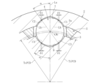
- FIG. 3 is a cross-sectional view showing angular contact between the track groove and the torque transmission ball of the sliding constant velocity universal joint of the present embodiment and internal play in the rotational direction.
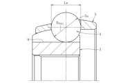
- FIG. 4 is a vertical cross-sectional view showing the axial clearance between the torque transmission balls and the pocket of the cage, and FIG. Fig.
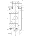
- FIG. 3 is a vertical cross-sectional view showing the axial clearance between and the spherical clearance between the spherical outer peripheral surface of the inner joint member and the spherical inner peripheral surface of the cage.
- FIG. 6 is a schematic diagram comparing a high normal working angle state and a conventional normal working angle state.
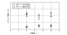
- FIG. 7 is a graph showing the slide resistance test results of the sliding constant velocity universal joint of this embodiment and a conventional standard specification product, and FIG. It is a graph which shows the test result of the amount of surface temperature rises of the outer joint member of a standard specification product.
- the sliding constant velocity universal joint 1 is a so-called double-offset sliding constant velocity universal joint (also abbreviated as DOJ).
- the inner joint member 3, the torque transmission balls 4 and the cage 5 are the main components.
- Eight track grooves 7 are formed in the cylindrical inner peripheral surface 6 of the outer joint member 2 at equal intervals in the circumferential direction and linearly along the axial direction.
- Track grooves 9 facing the track grooves 7 of the outer joint member 2 are formed on the spherical outer peripheral surface 8 of the inner joint member 3 at regular intervals in the circumferential direction and linearly along the axial direction.
- Balls 4 are housed in pockets 5 a of cage 5 .
- the cage 5 has a spherical outer peripheral surface 11 and a spherical inner peripheral surface 12.
- the spherical outer peripheral surface 11 is fitted and guided in contact with the cylindrical inner peripheral surface 6 of the outer joint member 2, and the spherical inner peripheral surface 12 is inside. It is engaged with and guided by the spherical outer peripheral surface 8 of the joint member 3 .
- the spherical outer peripheral surface 11 of the cage 5 is formed with a curvature radius Rc1 with a curvature center O1
- the spherical inner peripheral surface 12 is formed with a curvature radius Rc2 with a curvature center O2.
- a spherical outer peripheral surface 8 of the inner joint member 3 is formed with a radius of curvature Ri having a center of curvature O2.
- the centers of curvature O1, O2 are located on the axis N and are axially offset by an equal distance F with respect to the joint center O.
- a retaining ring groove 15 is provided in the opening side end of the outer joint member 2, and a retaining ring 17 is mounted in the retaining ring groove 15 to form the inner assembly of the inner joint member 3, the balls 4, and the cage 5 shown in FIG. prevents it from slipping out of the opening side end of the outer joint member 2 .
- a boot mounting groove 16 is provided on the outer circumference of the opening-side end of the outer joint member 2 .
- a stem portion (shaft portion) 2b is integrally formed on the side opposite to the opening of the outer joint member 2, and is connected to a differential (not shown).
- the linear track grooves 9 are formed in the spherical outer peripheral surface 8 of the inner joint member 3, the groove depth of the track grooves 9 becomes shallower from the axial center of the inner joint member 3 toward both ends.
- a spline (including serrations, the same shall apply hereinafter) 14 is formed in the connecting hole 13 of the inner joint member 3 , and an axial end of an intermediate shaft (not shown) is spline-fitted so that the inner joint member 3 is attached to the intermediate shaft shoulder. It is fixed in the axial direction by the part and the retaining ring.
- Eight pockets 5a are provided at equal intervals in the circumferential direction at the axial center of the cage 5 indicated by line AA in FIG. 1, and columns 5b (see FIG. 2) are formed between adjacent pockets 5a. .
- a notch 5c for incorporating the inner joint member 3 is provided on the inner periphery of the large-diameter end of the cage 5 .
- a stopper surface 5 d of the cage 5 is formed in a conical shape that is tangentially connected to the spherical outer peripheral surface 11 .
- the maximum operating angle is set at 25°, for example.
- the inclination angle S of the stopper surface 5d is set to 12.5°. there is Thereby, the maximum permissible angle of the sliding constant velocity universal joint 1 can be regulated.
- FIG. 3 shows one track groove 7, 9 and torque transmission ball 4 on line BN of FIG.
- the cross sections of the track groove 7 of the outer joint member 2 and the track groove 9 of the inner joint member 3 are formed in a Gothic arch shape combining two circular arcs. Therefore, the ball 4 is in angular contact with the track grooves 7 and 9 at two points C1, C2, C3 and C4.
- the cross-sectional shape of the track grooves 7 and 9 is not limited to the Gothic arch shape described above, and may be an elliptical shape.
- the pitch diameter of the track grooves 7 of the outer joint member 2 is ToPCD
- the pitch diameter of the track grooves 9 of the inner joint member 3 is TiPCD.
- ToPCD is set larger than TiPCD by, for example, about 0.050 mm in median value.
- the center Ob of the torque transmission ball 4 is positioned radially midway between ToPCD and TiPCD, and between the ball 4 and the track groove 7 of the outer joint member 2 and the track groove 9 of the inner joint member 3.
- a track gap is formed in the direction of the track contact angle ⁇ .
- a circumferential track clearance ⁇ 1 is generated based on the track clearance in the direction of the track contact angle ⁇ .
- the amount of backlash in the rotational direction inside the joint is set to 15 minutes or less, so torque load responsiveness in EV is also good. Further, since the cross-sectional shape of the track grooves 7 and 9 is formed in a Gothic arch shape, the amount of backlash in the rotational direction inside the joint can be reliably suppressed. In FIG. 3, the dimensional difference and track clearance between TiPCD and ToPCD are exaggerated.
- the track contact angle ⁇ is the angle ⁇ between the straight line La and the straight line Lb in FIG.
- a straight line La is the cross-sectional center line of the track grooves 7 and 9 and corresponds to the BN line in FIG.
- a straight line Lb is a straight line connecting the contact points C1, C2, C3, C4 of the balls 4 on the side surfaces of the track grooves 7, 9 and the center Ob of the balls 4.
- the spherical clearance of the standard DOJ is about 0.050 mm in median value that enables contact guidance between the spherical inner peripheral surface 12 of the cage 5 and the spherical outer peripheral surface 8 of the inner joint member 3. . Due to this spherical clearance, the amount of play in the axial direction between the cage 5 and the inner joint member 3 is about 0.15 mm. Therefore, the movable amount in the axial direction of the inner joint member 3 with respect to the outer joint member 2 is 0.30 mm, which is twice the amount of about 0.15 mm.
- the characteristic configuration of the sliding constant velocity universal joint 1 of this embodiment is as follows: Based on the standard type spherical surface specification that forms a spherical clearance that enables contact guidance between the inner peripheral surface and the spherical outer peripheral surface of the inner joint member, (2) a positive gap between the pocket of the cage and the torque transmission ball A sliding constant velocity universal joint with a new DOJ specification of forming an axial clearance of .
- FIG. 5 is an enlarged view of the essential part of FIG. The spherical clearance between is exaggerated and illustrated.
- a positive axial clearance ⁇ 2 is formed between the balls 4 and the pockets 5 a of the cage 5 .
- the positive axial clearance ⁇ 2 Lw-D BALL , and ⁇ 2 is preferably +0.001 mm to +0.050 mm. This allows the ball 4 to roll smoothly in the pocket 5a, increasing the rolling area of the ball 4 on the track grooves 7 and 9 of the outer joint member 2 and the inner joint member 3, thereby reducing slide resistance.
- ⁇ 2 is set to +0.001 mm to +0.050 mm.
- the spherical inner peripheral surface 12 of the cage 5 is formed with a radius of curvature Rc2 with a center of curvature O2
- the spherical outer peripheral surface 8 of the inner joint member 3 is formed with a radius of curvature Ri with a center of curvature O2.
- the spherical clearance ⁇ 3 between the spherical inner peripheral surface 12 of the cage 5 and the spherical outer peripheral surface 8 of the inner joint member 3 is 2 ⁇ (Rc2 ⁇ Ri), and the spherical clearance ⁇ 3 is about 0.050 mm in median.
- the spherical clearance ⁇ 3 means a spherical clearance that enables contact guidance between the spherical outer peripheral surface of the inner joint member and the spherical inner peripheral surface of the cage in the present specification and claims.
- the axial clearance ⁇ 4/2 on one side between the cage 5 and the inner joint member 3 due to the spherical clearance ⁇ 3 is about 0.15 mm, and the inner joint member 3 can move in the axial direction with respect to the outer joint member 2.
- the amount is 0.30 mm, which is twice as large as 0.15 mm.
- vibration can be sufficiently absorbed with the above range of movable amount in the axial direction. Therefore, the axial clearance ⁇ 4 between the cage 5 and the inner joint member 3 and the positive axial clearance ⁇ 2 between the balls 4 and the pocket 5a of the cage 5 work together to reduce the sliding resistance. can.
- FIG. 6 is a schematic diagram comparing the state of a high normal working angle (for example, about 10°) in recent SUVs and the state of a conventional normal working angle.
- the drive shaft 20 has a fixed constant velocity universal joint 21 at its outboard end connected to wheels W, and a sliding constant velocity universal joint 1 at its inboard end connected to a differential Df.
- the left half of FIG. 6 shows the state of the high normal operating angle ⁇ 1, and the right half shows the state of the conventional normal operating angle ⁇ 2.
- the normal operating angle ⁇ 1 is high, the height of the differential Df from the ground becomes higher by ⁇ h than when the conventional normal operating angle ⁇ 2 is used, and the running performance is enhanced.
- the load on the torque transmission ball increases.
- the normal operating angle in this specification refers to the operating angle generated by the sliding constant velocity universal joint of the drive shaft when the steering is set to the straight-ahead state in a vehicle with one passenger on a horizontal and flat road surface.
- Conventional normal operating angles of drive shafts of current passenger cars and the like are relatively small, and are usually used at about 6°.
- the durability of the DOJ type sliding constant velocity universal joint decreases as the working angle increases.
- the force acting on the ball during one rotation fluctuates according to the operating angle. A load will be applied. For example, if the normal operating angle increases from the current normal operating angle of 6° to 10°, the maximum load applied to the ball increases by about 20 to 30%.
- the test product is an NTN-designated EDJ using 8 balls, and the joint size is #104.
- the sliding resistance of the DOJ type sliding constant velocity universal joint 1 was analyzed, and as an effective countermeasure for reducing the sliding resistance, the positive axial clearance ⁇ 2 between the pocket 5a of the cage 5 and the balls 4 contributes. I found out. It was verified that by providing this positive axial clearance ⁇ 2, the rolling area on the grooves of the balls 4, the outer joint member 2, and the tracks 7 and 9 of the inner joint member 3 is increased, thereby reducing the slide resistance.
- FIG. 7 shows the slide resistance test results. ⁇ Test conditions> ⁇ Load torque: 98Nm ⁇ No rotation ⁇ Axial excitation amplitude: ⁇ 0.1mm (frequency 20Hz)
- the durability of the DOJ type sliding constant velocity universal joint 1 decreases as the working angle increases. As the operating angle increases, the load applied to the balls 4 increases, thereby increasing the track surface pressure. As a result, the heat generated during the rotation of the joint also increases, leading to a decrease in durability. As a countermeasure against this, providing a positive axial clearance ⁇ 2 between the pocket 5a of the cage 5 and the balls 4 is effective in suppressing heat generation. It was verified that the friction between the ball 4 and the grooves of the tracks 7 and 9 can be reduced by suppressing the slippage between them and making them roll.
- Fig. 8 shows the test results of the amount of temperature rise of the outer ring. The effect is particularly noticeable at a high normal working angle (10°). ⁇ Test conditions> ⁇ Load torque: 373 Nm ⁇ Number of revolutions: 200 rpm ⁇ Operating angle: 5°, 10°
- the DOJ type sliding constant velocity universal joint 1 using eight torque transmission balls 4 was exemplified. It can be carried out as appropriate within the range of one.
- a sliding constant velocity universal joint suitable for power transmission systems of automobiles and various industrial machines can be configured.
- the number of torque transmission balls 4 may be eight or more.
Landscapes
- Engineering & Computer Science (AREA)
- General Engineering & Computer Science (AREA)
- Mechanical Engineering (AREA)
- Arrangement And Driving Of Transmission Devices (AREA)
- Rolling Contact Bearings (AREA)
Abstract
Description
<試験条件>
・負荷トルク:98Nm
・回転なし
・軸方向加振幅:±0.1mm(周波数20Hz)
<試験条件>
・負荷トルク:373Nm
・回転数:200rpm
・作動角:5°、10°
2 外側継手部材
3 内側継手部材
4 トルク伝達ボール
5 ケージ
5a ポケット
6 円筒状内周面
7 トラック溝
8 球状外周面
9 トラック溝
11 球状外周面
12 球状内周面
DBALL ボール径
F オフセット量
O 継手中心
O1 曲率中心
O2 曲率中心
δ1 円周方向のトラックすきま
δ2 ボールとポケット間の正の軸方向すきま
δ3 球面すきま
δ4 ケージと内側継手部材間の軸方向すきま
Claims (5)
- 円筒状内周面に直線状の複数のトラック溝が軸方向に沿って形成された外側継手部材と、球状外周面に前記外側継手部材の直線状の複数のトラック溝に対向する直線状の複数のトラック溝が軸方向に沿って形成された内側継手部材と、前記外側継手部材の直線状の複数のトラック溝と前記内側継手部材の直線状の複数のトラック溝間に組込まれた複数のトルク伝達ボールと、前記トルク伝達ボールをポケットに収容し、前記外側継手部材の円筒状内周面と前記内側継手部材の球状外周面に接触案内される球状外周面と球状内周面を有するケージとからなり、前記ケージの球状外周面の曲率中心と球状内周面の曲率中心が、継手中心に対して軸方向の反対側にオフセットした摺動式等速自在継手において、
前記内側継手部材の球状外周面と前記ケージの球状内周面との間には接触案内を可能にする球面すきまが形成されると共に、
前記ケージのポケットと前記トルク伝達ボールとの間に正の軸方向すきまが形成されていることを特徴とする摺動式等速自在継手。 - 前記ケージのポケットと前記トルク伝達ボールとの間に正の軸方向すきまを+0.001mm~+0.050mmとしたことを特徴とする請求項1に記載の摺動式等速自在継手。
- 前記摺動式等速自在継手の内部の回転方向ガタ量を15分以下とした請求項1又は請求項2に記載の摺動式等速自在継手。
- 前記外側継手部材のトラック溝と前記内側継手部材のトラック溝のそれぞれの横断面形状を前記トルク伝達ボールとアンギュラ接触するゴシックアーチ形状としたことを特徴とする請求項1~3のいずれか一項に記載の摺動式等速自在継手。
- 前記複数のトルク伝達ボールの個数を5~8個としたことを特徴とする請求項1~4のいずれか一項に記載の摺動式等速自在継手。
Priority Applications (2)
| Application Number | Priority Date | Filing Date | Title |
|---|---|---|---|
| EP22861121.6A EP4394200A4 (en) | 2021-08-26 | 2022-08-05 | SUBMERSIBLE CONSTANT VELOCITY JOINT |
| US18/684,345 US20240426348A1 (en) | 2021-08-26 | 2022-08-05 | Plunging type constant velocity universal joint |
Applications Claiming Priority (2)
| Application Number | Priority Date | Filing Date | Title |
|---|---|---|---|
| JP2021-138190 | 2021-08-26 | ||
| JP2021138190A JP2023032205A (ja) | 2021-08-26 | 2021-08-26 | 摺動式等速自在継手 |
Publications (2)
| Publication Number | Publication Date |
|---|---|
| WO2023026831A1 true WO2023026831A1 (ja) | 2023-03-02 |
| WO2023026831A8 WO2023026831A8 (ja) | 2023-10-26 |
Family
ID=84774114
Family Applications (1)
| Application Number | Title | Priority Date | Filing Date |
|---|---|---|---|
| PCT/JP2022/030153 Ceased WO2023026831A1 (ja) | 2021-08-26 | 2022-08-05 | 摺動式等速自在継手 |
Country Status (5)
| Country | Link |
|---|---|
| US (1) | US20240426348A1 (ja) |
| EP (1) | EP4394200A4 (ja) |
| JP (1) | JP2023032205A (ja) |
| CN (2) | CN115727067A (ja) |
| WO (1) | WO2023026831A1 (ja) |
Families Citing this family (1)
| Publication number | Priority date | Publication date | Assignee | Title |
|---|---|---|---|---|
| KR102783816B1 (ko) * | 2024-09-26 | 2025-03-21 | 서한이노빌리티(주) | 등속 조인트 |
Citations (6)
| Publication number | Priority date | Publication date | Assignee | Title |
|---|---|---|---|---|
| JPH1073129A (ja) | 1996-06-28 | 1998-03-17 | Ntn Corp | 摺動型等速自在継手 |
| JP2002054650A (ja) | 2000-08-09 | 2002-02-20 | Ntn Corp | 摺動型等速自在継手およびそれを用いたドライブシャフト |
| JP2007085488A (ja) | 2005-09-22 | 2007-04-05 | Ntn Corp | 摺動式等速自在継手 |
| JP2007224995A (ja) * | 2006-02-22 | 2007-09-06 | Ntn Corp | 等速ジョイント |
| JP2010159775A (ja) * | 2009-01-06 | 2010-07-22 | Ntn Corp | 摺動式等速自在継手 |
| JP2019190550A (ja) * | 2018-04-24 | 2019-10-31 | Ntn株式会社 | プロペラシャフト用摺動式等速自在継手 |
Family Cites Families (1)
| Publication number | Priority date | Publication date | Assignee | Title |
|---|---|---|---|---|
| JP7292008B2 (ja) * | 2017-03-17 | 2023-06-16 | Ntn株式会社 | 後輪用ドライブシャフト専用の摺動式等速自在継手 |
-
2021
- 2021-08-26 JP JP2021138190A patent/JP2023032205A/ja active Pending
-
2022
- 2022-08-05 US US18/684,345 patent/US20240426348A1/en active Pending
- 2022-08-05 WO PCT/JP2022/030153 patent/WO2023026831A1/ja not_active Ceased
- 2022-08-05 EP EP22861121.6A patent/EP4394200A4/en not_active Withdrawn
- 2022-08-12 CN CN202210971321.0A patent/CN115727067A/zh active Pending
- 2022-08-12 CN CN202222129435.9U patent/CN218266870U/zh active Active
Patent Citations (6)
| Publication number | Priority date | Publication date | Assignee | Title |
|---|---|---|---|---|
| JPH1073129A (ja) | 1996-06-28 | 1998-03-17 | Ntn Corp | 摺動型等速自在継手 |
| JP2002054650A (ja) | 2000-08-09 | 2002-02-20 | Ntn Corp | 摺動型等速自在継手およびそれを用いたドライブシャフト |
| JP2007085488A (ja) | 2005-09-22 | 2007-04-05 | Ntn Corp | 摺動式等速自在継手 |
| JP2007224995A (ja) * | 2006-02-22 | 2007-09-06 | Ntn Corp | 等速ジョイント |
| JP2010159775A (ja) * | 2009-01-06 | 2010-07-22 | Ntn Corp | 摺動式等速自在継手 |
| JP2019190550A (ja) * | 2018-04-24 | 2019-10-31 | Ntn株式会社 | プロペラシャフト用摺動式等速自在継手 |
Non-Patent Citations (1)
| Title |
|---|
| See also references of EP4394200A4 |
Also Published As
| Publication number | Publication date |
|---|---|
| WO2023026831A8 (ja) | 2023-10-26 |
| CN115727067A (zh) | 2023-03-03 |
| CN218266870U (zh) | 2023-01-10 |
| EP4394200A4 (en) | 2024-12-18 |
| EP4394200A1 (en) | 2024-07-03 |
| US20240426348A1 (en) | 2024-12-26 |
| JP2023032205A (ja) | 2023-03-09 |
Similar Documents
| Publication | Publication Date | Title |
|---|---|---|
| US9581206B2 (en) | Fixed type constant velocity universal joint | |
| US11371564B2 (en) | Plunging type constant velocity universal joint | |
| US11359677B2 (en) | Plunging type constant velocity universal joint for rear-wheel drive shaft | |
| CN112020613B (zh) | 传动轴用滑动式等速万向联轴器 | |
| JP7437868B2 (ja) | プロペラシャフト用摺動式等速自在継手 | |
| JP2023032205A (ja) | 摺動式等速自在継手 | |
| US20110086714A1 (en) | Constant velocity joint | |
| JP7837162B2 (ja) | 摺動式等速自在継手 | |
| US12429095B2 (en) | Plunging-type constant velocity universal joint | |
| JP2024090755A (ja) | 摺動式等速自在継手 | |
| WO2023026826A1 (ja) | 摺動式等速自在継手 | |
| CN117249177B (en) | Sliding constant velocity universal joint | |
| US20080064509A1 (en) | Fixed Type Constant Velocity Universal Joint | |
| JP2023041415A (ja) | 摺動式等速自在継手 | |
| WO2025047345A1 (ja) | 摺動式等速自在継手及びこれを備えた車輪駆動装置 | |
| WO2026048425A1 (ja) | 摺動式等速自在継手 | |
| WO2026058629A1 (ja) | トリポード型等速自在継手 | |
| WO2026048422A1 (ja) | 摺動式等速自在継手 | |
| WO2017013993A1 (ja) | 固定式等速自在継手 | |
| WO2025187210A1 (ja) | トリポード型等速自在継手 | |
| KR20250005476A (ko) | 트라이포드 조인트 | |
| WO2026053728A1 (ja) | 固定式等速自在継手 | |
| WO2025192043A1 (ja) | 摺動式等速自在継手 | |
| JP2007113769A (ja) | 複合型等速自在継手 | |
| CN120720340A (zh) | 等速万向联轴器用外侧联轴器构件以及具备该构件的固定式等速万向联轴器 |
Legal Events
| Date | Code | Title | Description |
|---|---|---|---|
| 121 | Ep: the epo has been informed by wipo that ep was designated in this application |
Ref document number: 22861121 Country of ref document: EP Kind code of ref document: A1 |
|
| WWE | Wipo information: entry into national phase |
Ref document number: 18684345 Country of ref document: US |
|
| WWE | Wipo information: entry into national phase |
Ref document number: 2022861121 Country of ref document: EP |
|
| NENP | Non-entry into the national phase |
Ref country code: DE |
|
| ENP | Entry into the national phase |
Ref document number: 2022861121 Country of ref document: EP Effective date: 20240326 |
|
| WWW | Wipo information: withdrawn in national office |
Ref document number: 2022861121 Country of ref document: EP |