WO2023026855A1 - 二酸化炭素吸収還元溶液、二酸化炭素吸収還元装置、及び二酸化炭素吸収還元方法 - Google Patents
二酸化炭素吸収還元溶液、二酸化炭素吸収還元装置、及び二酸化炭素吸収還元方法 Download PDFInfo
- Publication number
- WO2023026855A1 WO2023026855A1 PCT/JP2022/030439 JP2022030439W WO2023026855A1 WO 2023026855 A1 WO2023026855 A1 WO 2023026855A1 JP 2022030439 W JP2022030439 W JP 2022030439W WO 2023026855 A1 WO2023026855 A1 WO 2023026855A1
- Authority
- WO
- WIPO (PCT)
- Prior art keywords
- carbon dioxide
- absorption
- reduction
- dioxide absorption
- reduction solution
- Prior art date
- Legal status (The legal status is an assumption and is not a legal conclusion. Google has not performed a legal analysis and makes no representation as to the accuracy of the status listed.)
- Ceased
Links
Images

Classifications
-
- B—PERFORMING OPERATIONS; TRANSPORTING
- B01—PHYSICAL OR CHEMICAL PROCESSES OR APPARATUS IN GENERAL
- B01D—SEPARATION
- B01D53/00—Separation of gases or vapours; Recovering vapours of volatile solvents from gases; Chemical or biological purification of waste gases, e.g. engine exhaust gases, smoke, fumes, flue gases, aerosols
- B01D53/14—Separation of gases or vapours; Recovering vapours of volatile solvents from gases; Chemical or biological purification of waste gases, e.g. engine exhaust gases, smoke, fumes, flue gases, aerosols by absorption
- B01D53/1456—Removing acid components
- B01D53/1475—Removing carbon dioxide
-
- B—PERFORMING OPERATIONS; TRANSPORTING
- B01—PHYSICAL OR CHEMICAL PROCESSES OR APPARATUS IN GENERAL
- B01D—SEPARATION
- B01D53/00—Separation of gases or vapours; Recovering vapours of volatile solvents from gases; Chemical or biological purification of waste gases, e.g. engine exhaust gases, smoke, fumes, flue gases, aerosols
- B01D53/14—Separation of gases or vapours; Recovering vapours of volatile solvents from gases; Chemical or biological purification of waste gases, e.g. engine exhaust gases, smoke, fumes, flue gases, aerosols by absorption
-
- B—PERFORMING OPERATIONS; TRANSPORTING
- B01—PHYSICAL OR CHEMICAL PROCESSES OR APPARATUS IN GENERAL
- B01D—SEPARATION
- B01D53/00—Separation of gases or vapours; Recovering vapours of volatile solvents from gases; Chemical or biological purification of waste gases, e.g. engine exhaust gases, smoke, fumes, flue gases, aerosols
- B01D53/34—Chemical or biological purification of waste gases
- B01D53/46—Removing components of defined structure
- B01D53/62—Carbon oxides
-
- B—PERFORMING OPERATIONS; TRANSPORTING
- B01—PHYSICAL OR CHEMICAL PROCESSES OR APPARATUS IN GENERAL
- B01D—SEPARATION
- B01D53/00—Separation of gases or vapours; Recovering vapours of volatile solvents from gases; Chemical or biological purification of waste gases, e.g. engine exhaust gases, smoke, fumes, flue gases, aerosols
- B01D53/34—Chemical or biological purification of waste gases
- B01D53/74—General processes for purification of waste gases; Apparatus or devices specially adapted therefor
- B01D53/77—Liquid phase processes
- B01D53/78—Liquid phase processes with gas-liquid contact
-
- B—PERFORMING OPERATIONS; TRANSPORTING
- B01—PHYSICAL OR CHEMICAL PROCESSES OR APPARATUS IN GENERAL
- B01J—CHEMICAL OR PHYSICAL PROCESSES, e.g. CATALYSIS OR COLLOID CHEMISTRY; THEIR RELEVANT APPARATUS
- B01J31/00—Catalysts comprising hydrides, coordination complexes or organic compounds
- B01J31/16—Catalysts comprising hydrides, coordination complexes or organic compounds containing coordination complexes
- B01J31/18—Catalysts comprising hydrides, coordination complexes or organic compounds containing coordination complexes containing nitrogen, phosphorus, arsenic or antimony as complexing atoms, e.g. in pyridine ligands, or in resonance therewith, e.g. in isocyanide ligands C=N-R or as complexed central atoms
- B01J31/1805—Catalysts comprising hydrides, coordination complexes or organic compounds containing coordination complexes containing nitrogen, phosphorus, arsenic or antimony as complexing atoms, e.g. in pyridine ligands, or in resonance therewith, e.g. in isocyanide ligands C=N-R or as complexed central atoms the ligands containing nitrogen
- B01J31/181—Cyclic ligands, including e.g. non-condensed polycyclic ligands, comprising at least one complexing nitrogen atom as ring member, e.g. pyridine
- B01J31/1815—Cyclic ligands, including e.g. non-condensed polycyclic ligands, comprising at least one complexing nitrogen atom as ring member, e.g. pyridine with more than one complexing nitrogen atom, e.g. bipyridyl, 2-aminopyridine
-
- B—PERFORMING OPERATIONS; TRANSPORTING
- B01—PHYSICAL OR CHEMICAL PROCESSES OR APPARATUS IN GENERAL
- B01J—CHEMICAL OR PHYSICAL PROCESSES, e.g. CATALYSIS OR COLLOID CHEMISTRY; THEIR RELEVANT APPARATUS
- B01J31/00—Catalysts comprising hydrides, coordination complexes or organic compounds
- B01J31/16—Catalysts comprising hydrides, coordination complexes or organic compounds containing coordination complexes
- B01J31/20—Carbonyls
-
- C—CHEMISTRY; METALLURGY
- C01—INORGANIC CHEMISTRY
- C01B—NON-METALLIC ELEMENTS; COMPOUNDS THEREOF; METALLOIDS OR COMPOUNDS THEREOF NOT COVERED BY SUBCLASS C01C
- C01B32/00—Carbon; Compounds thereof
- C01B32/40—Carbon monoxide
-
- C—CHEMISTRY; METALLURGY
- C25—ELECTROLYTIC OR ELECTROPHORETIC PROCESSES; APPARATUS THEREFOR
- C25B—ELECTROLYTIC OR ELECTROPHORETIC PROCESSES FOR THE PRODUCTION OF COMPOUNDS OR NON-METALS; APPARATUS THEREFOR
- C25B1/00—Electrolytic production of inorganic compounds or non-metals
- C25B1/01—Products
- C25B1/23—Carbon monoxide or syngas
-
- C—CHEMISTRY; METALLURGY
- C25—ELECTROLYTIC OR ELECTROPHORETIC PROCESSES; APPARATUS THEREFOR
- C25B—ELECTROLYTIC OR ELECTROPHORETIC PROCESSES FOR THE PRODUCTION OF COMPOUNDS OR NON-METALS; APPARATUS THEREFOR
- C25B3/00—Electrolytic production of organic compounds
- C25B3/01—Products
- C25B3/07—Oxygen containing compounds
-
- C—CHEMISTRY; METALLURGY
- C25—ELECTROLYTIC OR ELECTROPHORETIC PROCESSES; APPARATUS THEREFOR
- C25B—ELECTROLYTIC OR ELECTROPHORETIC PROCESSES FOR THE PRODUCTION OF COMPOUNDS OR NON-METALS; APPARATUS THEREFOR
- C25B3/00—Electrolytic production of organic compounds
- C25B3/20—Processes
- C25B3/25—Reduction
- C25B3/26—Reduction of carbon dioxide
-
- C—CHEMISTRY; METALLURGY
- C25—ELECTROLYTIC OR ELECTROPHORETIC PROCESSES; APPARATUS THEREFOR
- C25B—ELECTROLYTIC OR ELECTROPHORETIC PROCESSES FOR THE PRODUCTION OF COMPOUNDS OR NON-METALS; APPARATUS THEREFOR
- C25B9/00—Cells or assemblies of cells; Constructional parts of cells; Assemblies of constructional parts, e.g. electrode-diaphragm assemblies; Process-related cell features
-
- B—PERFORMING OPERATIONS; TRANSPORTING
- B01—PHYSICAL OR CHEMICAL PROCESSES OR APPARATUS IN GENERAL
- B01D—SEPARATION
- B01D2258/00—Sources of waste gases
- B01D2258/02—Other waste gases
- B01D2258/0283—Flue gases
-
- B—PERFORMING OPERATIONS; TRANSPORTING
- B01—PHYSICAL OR CHEMICAL PROCESSES OR APPARATUS IN GENERAL
- B01J—CHEMICAL OR PHYSICAL PROCESSES, e.g. CATALYSIS OR COLLOID CHEMISTRY; THEIR RELEVANT APPARATUS
- B01J2231/00—Catalytic reactions performed with catalysts classified in B01J31/00
- B01J2231/60—Reduction reactions, e.g. hydrogenation
- B01J2231/62—Reductions in general of inorganic substrates, e.g. formal hydrogenation, e.g. of N2
- B01J2231/625—Reductions in general of inorganic substrates, e.g. formal hydrogenation, e.g. of N2 of CO2
-
- B—PERFORMING OPERATIONS; TRANSPORTING
- B01—PHYSICAL OR CHEMICAL PROCESSES OR APPARATUS IN GENERAL
- B01J—CHEMICAL OR PHYSICAL PROCESSES, e.g. CATALYSIS OR COLLOID CHEMISTRY; THEIR RELEVANT APPARATUS
- B01J2531/00—Additional information regarding catalytic systems classified in B01J31/00
- B01J2531/70—Complexes comprising metals of Group VII (VIIB) as the central metal
- B01J2531/72—Manganese
-
- B—PERFORMING OPERATIONS; TRANSPORTING
- B01—PHYSICAL OR CHEMICAL PROCESSES OR APPARATUS IN GENERAL
- B01J—CHEMICAL OR PHYSICAL PROCESSES, e.g. CATALYSIS OR COLLOID CHEMISTRY; THEIR RELEVANT APPARATUS
- B01J2531/00—Additional information regarding catalytic systems classified in B01J31/00
- B01J2531/70—Complexes comprising metals of Group VII (VIIB) as the central metal
- B01J2531/74—Rhenium
-
- B—PERFORMING OPERATIONS; TRANSPORTING
- B01—PHYSICAL OR CHEMICAL PROCESSES OR APPARATUS IN GENERAL
- B01J—CHEMICAL OR PHYSICAL PROCESSES, e.g. CATALYSIS OR COLLOID CHEMISTRY; THEIR RELEVANT APPARATUS
- B01J2531/00—Additional information regarding catalytic systems classified in B01J31/00
- B01J2531/80—Complexes comprising metals of Group VIII as the central metal
- B01J2531/84—Metals of the iron group
- B01J2531/842—Iron
-
- B—PERFORMING OPERATIONS; TRANSPORTING
- B01—PHYSICAL OR CHEMICAL PROCESSES OR APPARATUS IN GENERAL
- B01J—CHEMICAL OR PHYSICAL PROCESSES, e.g. CATALYSIS OR COLLOID CHEMISTRY; THEIR RELEVANT APPARATUS
- B01J2531/00—Additional information regarding catalytic systems classified in B01J31/00
- B01J2531/90—Catalytic systems characterized by the solvent or solvent system used
-
- B—PERFORMING OPERATIONS; TRANSPORTING
- B01—PHYSICAL OR CHEMICAL PROCESSES OR APPARATUS IN GENERAL
- B01J—CHEMICAL OR PHYSICAL PROCESSES, e.g. CATALYSIS OR COLLOID CHEMISTRY; THEIR RELEVANT APPARATUS
- B01J2540/00—Compositional aspects of coordination complexes or ligands in catalyst systems
- B01J2540/10—Non-coordinating groups comprising only oxygen beside carbon or hydrogen
-
- B—PERFORMING OPERATIONS; TRANSPORTING
- B01—PHYSICAL OR CHEMICAL PROCESSES OR APPARATUS IN GENERAL
- B01J—CHEMICAL OR PHYSICAL PROCESSES, e.g. CATALYSIS OR COLLOID CHEMISTRY; THEIR RELEVANT APPARATUS
- B01J2540/00—Compositional aspects of coordination complexes or ligands in catalyst systems
- B01J2540/10—Non-coordinating groups comprising only oxygen beside carbon or hydrogen
- B01J2540/12—Carboxylic acid groups
Definitions
- the present disclosure relates to a carbon dioxide absorption-reduction solution, a carbon dioxide absorption-reduction device, and a carbon dioxide absorption-reduction method.
- This application claims priority based on Japanese Patent Application No. 2021-137715 filed with the Japan Patent Office on August 26, 2021, the content of which is incorporated herein.
- Non-Patent Document 1 A method for reducing carbon dioxide using such a catalyst is described in Non-Patent Document 1, for example.
- gas containing carbon dioxide often contains water, and when the gas containing water is supplied to the electrolyte solution of the metal complex, which is a catalyst, the metal complex is water-insoluble. Since the complex does not dissolve in water, the problem is that it precipitates out.
- the concentration of the metal complex in the electrolyte solution is suppressed to a low concentration of 0.5 mM for the purpose of preventing such precipitation of the metal complex. Therefore, there is a problem that the reduction efficiency of carbon dioxide is low.
- At least one embodiment of the present disclosure provides a carbon dioxide absorption/reduction solution, a carbon dioxide absorption/reduction device, and a carbon dioxide absorption/reduction that can suppress deposition of a metal complex as a catalyst for carbon dioxide absorption/reduction.
- the purpose is to provide a method.
- the carbon dioxide absorption-reduction solution according to the present disclosure is a carbon dioxide absorption-reduction solution containing 0.01 to 100 mM of a metal complex in a mixed solvent of water and a water-soluble solvent, wherein the metal complex contains a metal center, which is either rhenium, manganese, or iron, and ligands coordinated to the metal center, the ligands comprising two or more carbonyl groups and two or more nitrogen atoms containing heterocycles, wherein at least one of said two or more nitrogen atom-containing heterocycles has at least one substituent containing a carboxy group or a hydroxy group.
- the metal complex contains a metal center, which is either rhenium, manganese, or iron, and ligands coordinated to the metal center, the ligands comprising two or more carbonyl groups and two or more nitrogen atoms containing heterocycles, wherein at least one of said two or more nitrogen atom-containing heterocycles has at least one substituent containing a carboxy group or
- the carbon dioxide absorption-reduction solution according to the present disclosure is a carbon dioxide absorption-reduction solution containing 0.01 to 100 mM of a metal complex in a mixed solvent of water and a water-soluble solvent, wherein the metal complex comprises ruthenium, a ligand that coordinates to the ruthenium, said ligand comprising two or more carbonyl groups and two or more nitrogen atom-containing heterocycles.
- precipitation of a metal complex can be suppressed by dissolving a water-soluble metal complex as a catalyst for carbon dioxide absorption-reduction in a mixed solvent of water and a water-soluble solvent. can.
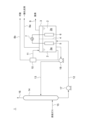
- FIG. 1 is a configuration schematic diagram of a carbon dioxide absorption-reduction device according to an embodiment of the present disclosure
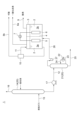
- FIG. FIG. 4 is a schematic diagram of the configuration of a carbon dioxide absorption-reduction device according to a modified example of the present disclosure
- FIG. 10 is a schematic diagram of the configuration of a carbon dioxide absorption-reduction device according to another modified example of the present disclosure
- the carbon dioxide absorption-reduction solution according to one embodiment of the present disclosure is used as an electrolytic solution for electrolysis, and the carbon dioxide supplied to the electrolytic solution is electrolyzed to produce valuable substances such as carbon monoxide and formic acid. is reduced to
- This carbon dioxide absorption reduction solution contains a metal complex in a mixed solvent of water and a water-soluble solvent.
- the concentration of the metal complex in the mixed solvent is 0.01 to 100 mM, which is disclosed in a document (Japanese Patent No. 6615175) based on prior research by one of the inventors of the present application.
- the concentration of the water-soluble solvent in the mixed solvent is preferably 1% by mass or more and 60% by mass or less, more preferably 10% by mass or more and 50% by mass or less, and most preferably 20% by mass or more and 40% by mass or less.
- a metal complex represented by the following molecular structure (1) or (2) can be used.
- M which is the central metal of the metal complex
- the metal complex comprises at least two carbonyl groups, at least two nitrogen atom-containing heterocycles A and B as ligands of the central metal (M and ruthenium), and ligands X and Y are included.
- Each of the ligands X and Y is not limited, but may be any functional group such as a linear or cyclic alkyl group or a functional group containing any of oxygen, nitrogen, sulfur, phosphorus and halogen. , a carbonyl group or a nitrogen atom-containing heterocyclic ring, or water or a hydroxy group.
- At least two nitrogen atom-containing heterocycles may have the same structure or different structures. Further, at least one of the two nitrogen atom-containing heterocycles A and B of the metal complex represented by the molecular structure (1) serves as a functional group as a substituent containing a hydroxy group (-R-OH/-R' —OH). In the molecular structure (1), both the nitrogen atom-containing heterocycles A and B have a substituent containing a hydroxy group. There may be. When it has three or more heterocycles containing a nitrogen atom, at least one nitrogen atom-containing heterocycle may have a substituent containing a hydroxy group. By having a substituent containing a hydroxy group, the metal complex represented by the molecular structure (1) has water-soluble properties.
- the metal complex represented by the molecular structure (2) with ruthenium as the central metal has water-soluble properties even if the nitrogen atom-containing heterocycles A and B do not contain a substituent containing a hydroxy group. Also in the metal complex represented by structure (2), at least one of the nitrogen atom-containing heterocycles A and B may have a substituent containing a hydroxy group.
- a water-soluble solvent is a liquid containing an organic compound with a hydroxyl group or a carboxyl group.
- organic compounds include alcohols, glycols, phenols, phenol derivatives, alkanolamines, and amino acids. Even an organic compound having a hydroxyl group or a carboxyl group is less soluble in water if the number of carbon atoms is too large, so a substance with a small number of carbon atoms is preferable.
- alcohols are preferably methyl alcohol, ethyl alcohol, 1-propyl alcohol, or 2-propyl alcohol.
- alkanolamines have the property of absorbing carbon dioxide, carbon dioxide can be efficiently reduced by using alkanolamines as a water-soluble solvent.
- Alkanolamines can be classified according to the structure of primary amine, secondary amine, and tertiary amine, and although there is a difference in the ability to absorb carbon dioxide among the amines of each structure, the amount of carbon dioxide is higher than that of other organic compounds. Alkanolamines of any structure may be used due to their high carbon absorption properties.
- amino acids include, but are not limited to, glycine and alanine. Since they are solid at room temperature, they are dissolved in water or other liquid organic compounds before use.
- the mixed solvent preferably contains an inorganic carbonate, an inorganic hydroxide or an inorganic salt.
- inorganic carbonates that can be used include sodium carbonate, potassium carbonate, calcium carbonate, and the like.
- inorganic hydroxides that can be used include sodium hydroxide, potassium hydroxide, and calcium hydroxide.
- inorganic salts for example, carbonates, nitrates, sulfates and the like can be used. If such a salt does not exist in the mixed solvent, the ionic conductivity of the carbon dioxide-absorbing reducing solution is low and the electrolytic reaction may be difficult to occur with only 0.01 to 100 mM metal complex. On the other hand, when such salts are present in the mixed solvent, it is possible to maintain the ionic conductivity necessary for advancing the reduction reaction by electrolysis of carbon dioxide in the carbon dioxide absorption-reduction solution.
- a carbon dioxide absorption-reduction device 1 includes an electrolyzer 3 containing the carbon dioxide absorption-reduction solution 2 described above.
- the interior of the electrolyzer 3 is partitioned by a diaphragm 4 into a first chamber 3a and a second chamber 3b.
- a cathode 5 is provided so as to be immersed in the carbon dioxide absorbing and reducing solution 2 in the first chamber 3a
- an anode 6 is provided so as to be immersed in the carbon dioxide absorbing and reducing solution 2 in the second chamber 3b.
- Cathode 5 and anode 6 are each electrically connected to DC power supply 7 .
- the electrolyzer 3 is not limited to the configuration shown in FIG. 1, that is, the configuration in which the cathode 5 and the anode 6 are immersed in the carbon dioxide absorption-reduction solution 2 in the electrolytic cell.
- Another example configuration comprises an electrolytic cell, a power source electrically connected to the electrolytic cell, piping for supplying liquid or gaseous reactants to the electrolytic cell, and piping for discharging the products. Anything is fine.
- the electrolytic cell is composed of an anode section, a cathode section, an electrolyte section, and an electrolytic cell container having an anode terminal and a cathode terminal.
- the anode part electrically connected to the terminal and the cathode part electrically connected to the cathode terminal may be arranged so as to face each other.
- the anode part and the cathode part may be composed of a single member, and a catalyst electrode layer that promotes the electrolysis reaction may be provided on the power supply substrate.
- a diaphragm for separating the product of the anode part and the product of the cathode part may be arranged in the electrolyte part between the anode part and the cathode part.
- a porous membrane impregnated with an electrolytic solution, an ion-permeable non-porous membrane, or the like can be used for this diaphragm.
- the anode section, the cathode section, and the diaphragm may be arranged apart from each other, or may be arranged so as to be in contact with each other, and the two may be integrally joined together.
- it may have an electrode assembly membrane in which electrodes (cathode 5 and anode 6) and an ion exchange membrane are joined.
- first outflow lines 8a and 8b Connected to the carbon dioxide absorption-reduction device 1 are first outflow lines 8a and 8b through which carbon monoxide and formic acid respectively flow out from the first chamber 3a, and a second outflow line 9 through which oxygen flows out from the second chamber 3b. It is A first outflow line 8a is provided in communication with the gas phase portion of the first chamber 3a so that the carbon monoxide produced in the first chamber 3a can flow out of the first chamber 3a.
- the first outflow line 8b is provided so as to communicate with the liquid phase portion of the first chamber 3a so that the carbon dioxide absorption-reduction solution 2 containing formic acid produced in the first chamber 3a can flow out from the first chamber 3a
- the first outflow line 8b is provided with a separation device 10, such as a distillation device or a membrane separation device, for separating formic acid from the carbon dioxide-absorbed reducing solution 2 flowing out from the first chamber 3a.
- a return line 11 may be provided to return the carbon dioxide-absorbing reducing solution 2 to the first chamber 3a. Incidentally, if only carbon monoxide is produced in the first chamber 3a and no formic acid is produced, the separation device 10 need not be provided.
- an absorption tower configured so that gas containing carbon dioxide and the carbon dioxide absorption-reduction solution 2 as an absorption liquid are in gas-liquid contact. 14 can be provided.
- the absorption tower 14 has a gas supply line 15 for supplying a gas containing carbon dioxide, such as combustion gas, to the absorption tower 14, and a gas outflow line for flowing out the gas from which carbon dioxide has been removed from the absorption tower 14. 16 are connected.
- the supply line 12 is connected to the bottom of the absorber tower 14 and the outlet line 13 is connected to the absorber tower 14 above the position where the gas supply line 15 is connected to the absorber tower 14 .
- Supply line 12 and outflow line 13 are provided with pumps 17 and 18, respectively.
- FIG. 2 shows several forms of the carbon dioxide absorption/reduction device 1 configured to reduce carbon dioxide in a batch manner as described above.
- the carbon dioxide absorption-reduction device 1 shown in FIG. 2 is a carbon dioxide recovery device 20 for recovering carbon dioxide from a gas containing carbon dioxide, and is configured such that the gas containing carbon dioxide and the absorption liquid are in gas-liquid contact. It has an absorption tower 14 and a regeneration tower 21 for releasing carbon dioxide from the absorbent that has absorbed carbon dioxide in the absorption tower 14 .
- the absorption liquid used in the absorption tower 14 is different from the carbon dioxide absorption-reduction solution 2.
- Absorption tower 14 and regeneration tower 21 are connected by supply line 12 .
- the regeneration tower 21 has a heat medium flow passage 22 through which a heat medium (e.g., steam) flows and an absorbent circulation passage 24 through which the absorbent in the regeneration tower 21 flows out of the regeneration tower 21 and circulates back to the regeneration tower 21.
- a heat exchanger (reboiler) 23 is provided, and is configured to exchange heat between the heat medium flowing through the heat medium flow path 22 and the absorbent flowing through the absorbing liquid circulation path 24 .
- a withdrawal line 25 for withdrawing the absorbent is connected to the bottom of the regeneration tower 21 .
- the other end of a gas supply line 26, one end of which is connected to the bottom of the first chamber 3a of the electrolyzer 3, is connected to the top of the regeneration tower 21, and the gas supply line 26 is provided with a compressor 27.
- the carbon dioxide recovery device 20 is not limited to the above-described configuration including the absorption tower 14 and the regeneration tower 21. Any configuration can be used as long as it can recover carbon dioxide from a gas containing carbon dioxide and supply the recovered carbon dioxide to the carbon dioxide absorption-reduction solution 2 in the first chamber 3a of the electrolyzer 3. good.
- the carbon dioxide absorption-reduction device 1 shown in FIG. The membrane separation device 30 is connected to a gas outflow line 16 through which the gas from which the carbon dioxide is separated flows out from the membrane separation device 30 .
- the membrane separator 30 and the bottom of the first chamber 3a are connected by a gas supply line 26 so that the separated carbon dioxide can be supplied into the first chamber 3a.
- a compressor 27 is provided in the gas supply line 26 .
- the rising combustion gas and the falling absorption liquid come into gas-liquid contact, whereby the carbon dioxide contained in the combustion gas is absorbed by the absorption liquid, and the combustion gas from which the carbon dioxide has been removed flows out of the gas.
- Absorber tower 14 exits via line 16 .
- the absorbent that has absorbed carbon dioxide stays in the lower part of the absorption tower 14, but the absorption liquid is extracted from the absorption tower 14 by the pump 17 and sent to the first chamber 3a of the electrolyzer 3 through the supply line 12. supplied.
- the carbon monoxide generated in the first chamber 3a flows out of the first chamber 3a through the first outflow line 8a and is sent to equipment that uses carbon monoxide or storage equipment for carbon monoxide.
- the formic acid produced in the first chamber 3a flows out of the first chamber 3a together with the carbon dioxide absorption-reduction solution 2 through the first outflow line 8b, and the formic acid is separated from the carbon dioxide absorption-reduction solution 2 in the separation device 10, It is sent to a facility that uses formic acid or a storage facility for formic acid.
- the carbon dioxide-absorbed reducing solution 2 from which the formic acid has been separated in the separation device 10 can be returned to the first chamber 3a via the return line 11.
- Oxygen produced in the second chamber 3b flows out of the second chamber 3b through a second outflow line 9 and is sent to a facility that uses oxygen, a facility that stores oxygen, or the like.
- the carbon dioxide absorption-reduction solution 2 flowing through the outflow line 13 is supplied to the absorption tower 14, drops inside the absorption tower 14, and comes into gas-liquid contact with the combustion gas rising inside the absorption tower 14 as an absorption liquid.
- the gas containing carbon dioxide and the absorbing liquid come into gas-liquid contact in the absorption tower 14, whereby the absorbing liquid absorbs carbon dioxide.
- the absorbent that has absorbed carbon dioxide is supplied to the regeneration tower 21 through the supply line 12 .
- the absorbing liquid is heated by the heat exchanger 23 to release carbon dioxide.
- the released carbon dioxide is supplied by the compressor 27 through the gas supply line 26 into the first chamber 3a. At least part of the carbon dioxide supplied into the first chamber 3 dissolves in the carbon dioxide absorption-reduction solution 2 .
- the DC power supply 7 After dissolving a certain amount of carbon dioxide in the carbon dioxide absorption-reduction solution 2, the DC power supply 7 applies a voltage between the cathode 5 and the anode 6, thereby dissolving in the carbon dioxide absorption-reduction solution 2 according to the principle described above. The carbon dioxide produced is reduced.
- carbon dioxide is separated from a gas containing carbon dioxide in the membrane separation device 30 .
- the separated carbon dioxide is supplied into the first chamber 3a through the gas supply line 26 by the compressor 27.
- At least part of the carbon dioxide supplied into the first chamber 3 dissolves in the carbon dioxide absorption-reduction solution 2 .
- the DC power supply 7 applies a voltage between the cathode 5 and the anode 6, thereby dissolving in the carbon dioxide absorption-reduction solution 2 according to the principle described above.
- the carbon dioxide produced is reduced.
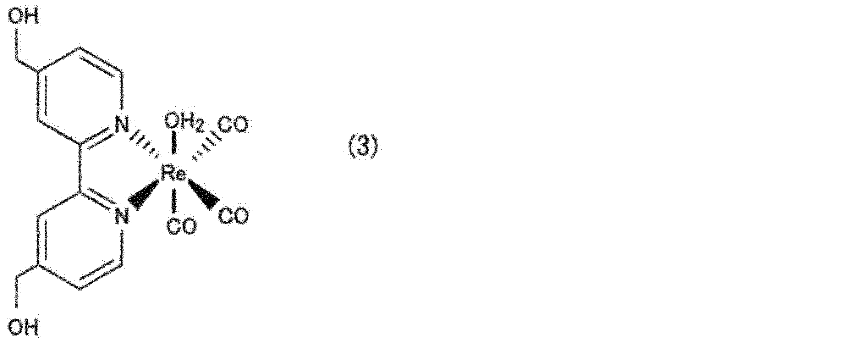
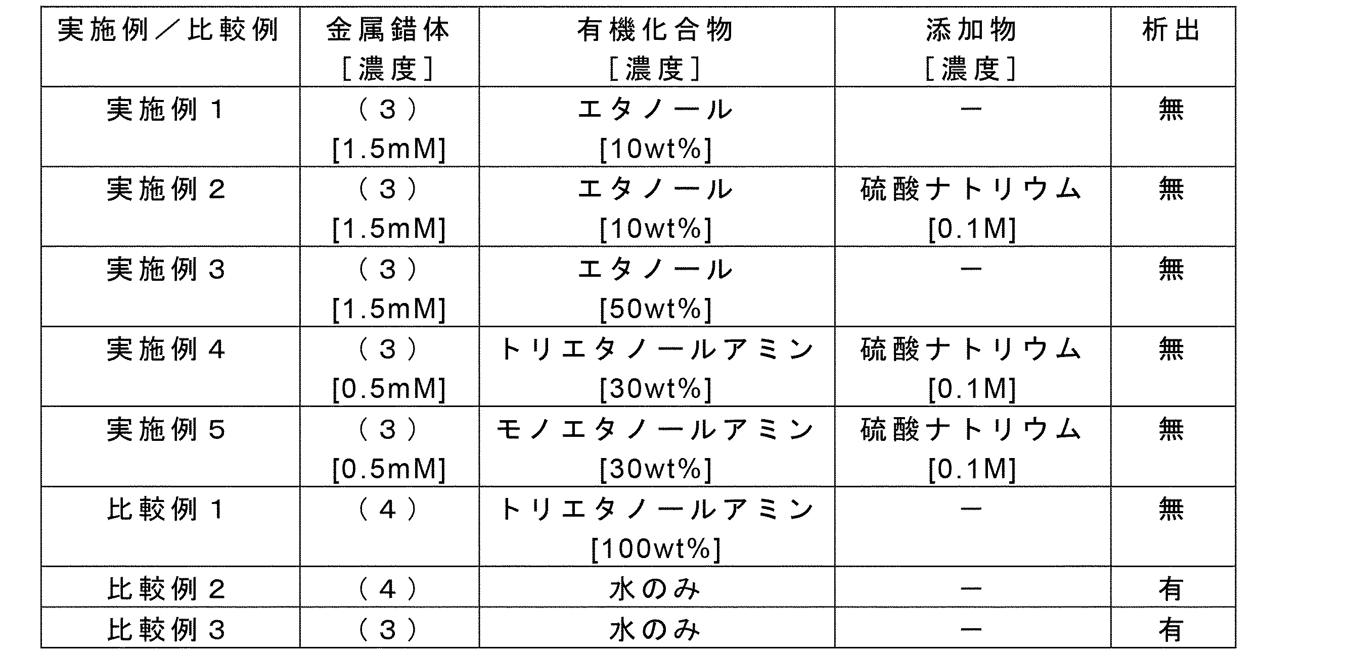
- Metal complex (3) corresponds to molecular structure (1)
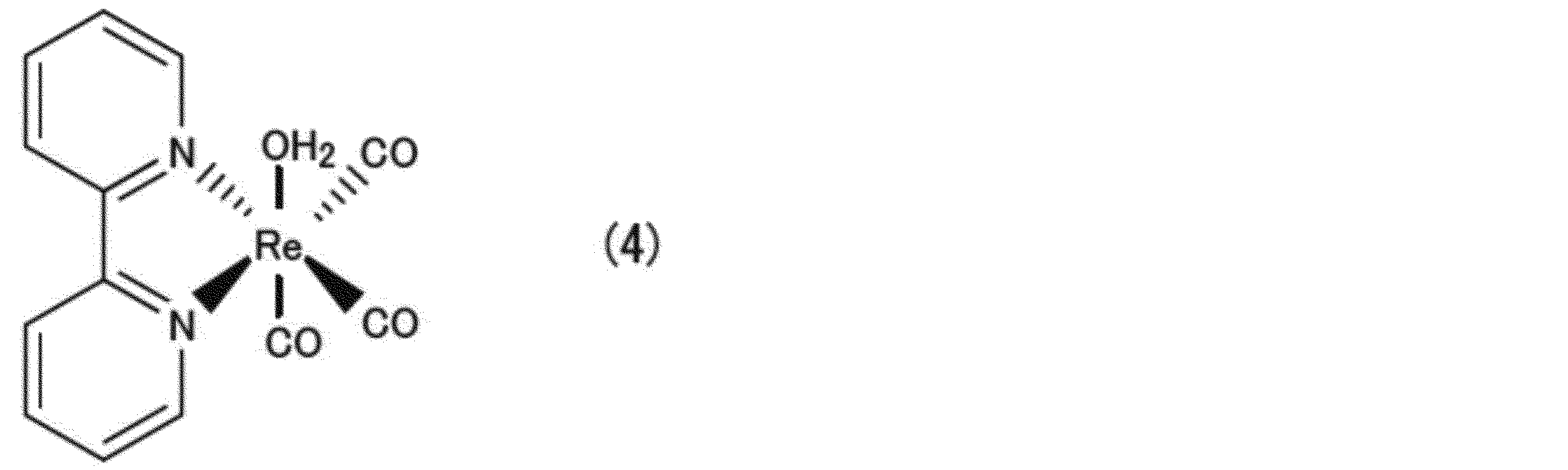
- metal complex (4) does not correspond to molecular structure (1) because the nitrogen atom-containing heterocycle does not contain a hydroxyalkyl group.
- Examples 1 to 5 and Comparative Example 1 contain a trace amount of water. After confirming that the metal complex was completely dissolved in each solution, a carbon dioxide-containing gas (carbon dioxide concentration: 10 vol %) was blown into each solution to confirm the presence or absence of precipitation of the complex.
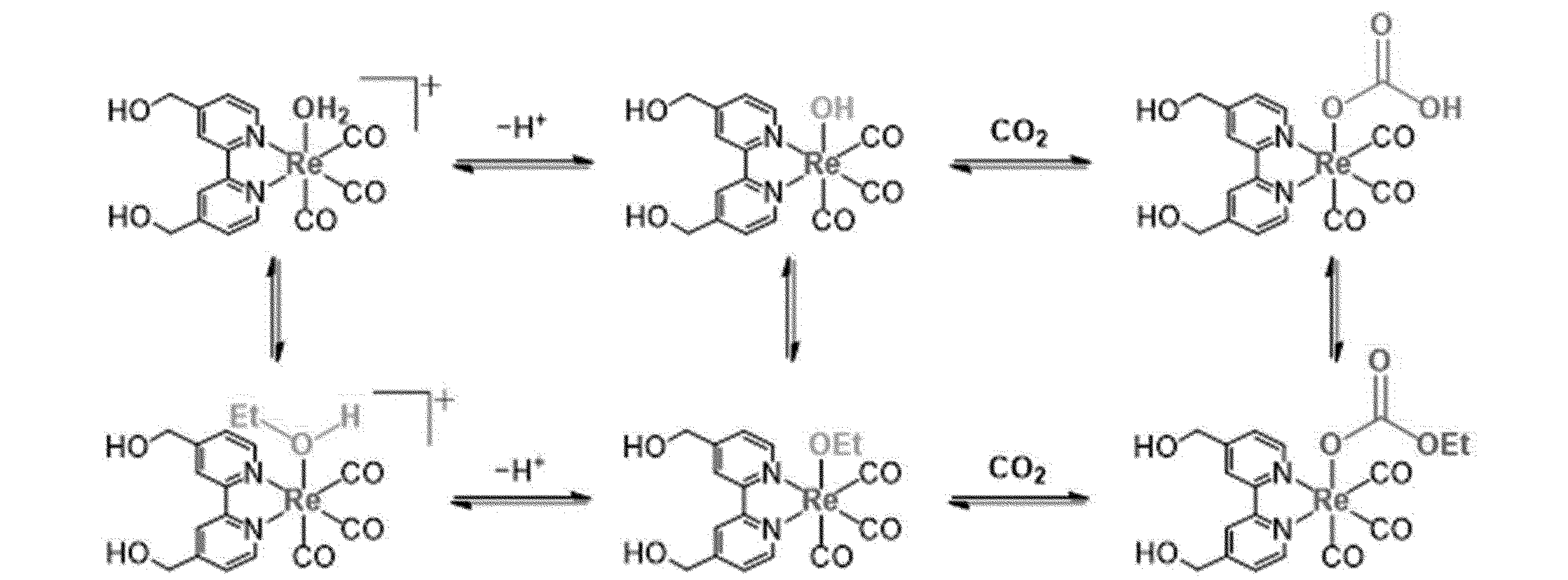
- Example 1 Under the conditions where water and ethanol coexist as in Example 1, the complexes with Re as the central metal change into a total of six types of complexes as follows due to the equilibrium reaction of each complex formed. As a result, deposition of the metal complex can be suppressed or prevented. Based on this mechanism, carbon dioxide can be added without precipitating the metal complex by using a water-soluble metal complex under conditions where water and a water-soluble solvent coexist.
- a carbon dioxide absorption-reduction solution is A carbon dioxide absorption-reduction solution (2) containing 0.01 to 100 mM of a metal complex in a mixed solvent of water and a water-soluble solvent,
- the metal complex is a central metal that is either rhenium, manganese, or iron; and a ligand that coordinates to the central metal,
- the ligand comprises two or more carbonyl groups and two or more nitrogen atom-containing heterocycles, wherein at least one of the two or more nitrogen atom-containing heterocycles comprises at least one carboxyl group or hydroxy group. have one substituent.
- precipitation of a metal complex can be suppressed by dissolving a water-soluble metal complex as a catalyst for carbon dioxide absorption-reduction in a mixed solvent of water and a water-soluble solvent. can.
- a carbon dioxide absorption-reduction solution is the carbon dioxide absorption-reduction solution of [1]
- Said ligand comprises two or more carbonyl groups and two or more nitrogen atom-containing heterocycles, at least one of said two or more nitrogen atom-containing heterocycles being at least one hydroxymethyl group or hydroxyethyl or carboxy group.
- Metal complexes exhibit water-soluble properties due to the presence of hydroxyl groups at the terminals of the side chains of the nitrogen atom-containing heterocycles of the ligands coordinating to the central metal. ceases to exhibit water-soluble properties.
- the hydroxyalkyl group is a hydroxymethyl group, a hydroxyethyl group, or a carboxy group as in the configuration [2] above, the metal complex exhibits water-soluble properties, and the metal complex is precipitated. can be suppressed.
- a carbon dioxide absorption-reduction solution is A carbon dioxide absorption-reduction solution containing 0.01 to 100 mM of a metal complex in a mixed solvent of water and a water-soluble solvent,
- the metal complex is ruthenium; and a ligand that coordinates to ruthenium,
- the ligand contains two or more carbonyl groups and two or more nitrogen atom-containing heterocycles.
- precipitation of a metal complex can be suppressed by dissolving a water-soluble metal complex as a catalyst for carbon dioxide absorption-reduction in a mixed solvent of water and a water-soluble solvent. can.
- a carbon dioxide absorption-reduction solution according to another aspect is the carbon dioxide absorption-reduction solution according to any one of [1] to [3],
- the water-soluble solvent is a liquid containing an organic compound having a hydroxyl group.
- the water-soluble metal complex dissolves in the mixed solvent, so precipitation of the metal complex can be suppressed.
- a carbon dioxide absorption-reduction solution according to still another aspect is the carbon dioxide absorption-reduction solution of [4],
- the organic compound is methyl alcohol, ethyl alcohol, 1-propyl alcohol, or 2-propyl alcohol.
- the water-soluble metal complex dissolves in the mixed solvent, so precipitation of the metal complex can be suppressed.
- a carbon dioxide absorption-reduction solution according to still another aspect is the carbon dioxide absorption-reduction solution of [4],
- the organic compound is an alkanolamine.
- carbon dioxide can be efficiently reduced by using an alkanolamine capable of absorbing carbon dioxide as a water-soluble solvent.
- a carbon dioxide absorption-reduction solution according to still another aspect is the carbon dioxide absorption-reduction solution according to any one of [1] to [6],
- the mixed solvent includes an inorganic carbonate, an inorganic hydroxide, or an inorganic salt.
- a carbon dioxide absorption-reduction solution according to still another aspect is the carbon dioxide absorption-reduction solution according to any one of [1] to [7],
- the water-soluble solvent contains an amino acid.
- the water-soluble metal complex dissolves in the mixed solvent, so precipitation of the metal complex can be suppressed.
- a carbon dioxide absorption-reduction device includes: An electrolyzer (3) containing the carbon dioxide absorption-reduction solution (2) according to any one of [1] to [8] is provided.
- precipitation of the metal complex can be suppressed by dissolving the water-soluble metal complex as a catalyst for carbon dioxide absorption reduction in a mixed solvent of water and a water-soluble solvent. can. Thereby, the reduction efficiency of carbon dioxide can be improved.
- a carbon dioxide absorption-reduction device is the carbon dioxide absorption-reduction device of [9], a supply line (12) for supplying the carbon dioxide-absorbing and reducing solution that has absorbed carbon dioxide into the electrolyzer (3); and an outflow line (13) through which the carbon dioxide absorption-reduction solution (2) flows out from the electrolyzer (3).
- a carbon dioxide absorption-reduction device is the carbon dioxide absorption-reduction device of [10], further comprising an absorption tower (14) for bringing a gas containing carbon dioxide into contact with the carbon dioxide absorption-reduction solution to cause the carbon dioxide absorption-reduction solution to absorb carbon dioxide;
- the carbon dioxide absorption-reduction solution that has absorbed carbon dioxide in the absorption tower (14) is supplied through the supply line (12) into the electrolyzer (3), and through the outflow line (13).
- the carbon dioxide absorption-reduction solution (2) flowing out from the electrolyzer (3) is supplied to the absorption tower (14) and comes into contact with the gas.
- a carbon dioxide absorption-reduction device is the carbon dioxide absorption-reduction device of [9], a carbon dioxide recovery device (20) for recovering carbon dioxide from a gas containing carbon dioxide; and a gas supply line (26) for supplying carbon dioxide recovered in the carbon dioxide recovery device (20) to the carbon dioxide absorption-reduction solution (2) contained in the electrolyzer (3).
- the carbon dioxide recovered from the gas containing carbon dioxide can be reduced batchwise.
- a carbon dioxide absorption-reduction device is the carbon dioxide absorption-reduction device of [12],
- the carbon dioxide recovery device (20) an absorption tower (14) in which the gas containing carbon dioxide is brought into contact with an absorption liquid to absorb carbon dioxide in the absorption liquid;
- the carbon dioxide released in the regeneration tower (21) is supplied to the carbon dioxide absorption-reduction solution (2) contained in the electrolyzer (3) through the gas supply line (26).
- the carbon dioxide recovered from the gas containing carbon dioxide can be reduced batchwise.
- a carbon dioxide absorption reduction method includes: a step of supplying carbon dioxide to the carbon dioxide absorption-reduction solution (2) according to any one of [1] to [8]; and electrolyzing the carbon dioxide absorption-reduction solution (2) supplied with carbon dioxide.
- precipitation of a metal complex can be suppressed by dissolving a water-soluble metal complex as a catalyst for carbon dioxide absorption reduction in a mixed solvent of water and a water-soluble solvent. can. Thereby, the reduction efficiency of carbon dioxide can be improved.
- a carbon dioxide absorption-reduction method is the carbon dioxide absorption-reduction method of [14], At least one of carbon monoxide and formic acid is produced by electrolyzing the carbon dioxide absorbing and reducing solution (2).
- carbon dioxide by reducing carbon dioxide to produce at least one of carbon monoxide and formic acid, carbon dioxide can be converted into a valuable substance and used.
Landscapes
- Chemical & Material Sciences (AREA)
- Engineering & Computer Science (AREA)
- Chemical Kinetics & Catalysis (AREA)
- Organic Chemistry (AREA)
- Oil, Petroleum & Natural Gas (AREA)
- Analytical Chemistry (AREA)
- General Chemical & Material Sciences (AREA)
- Materials Engineering (AREA)
- Environmental & Geological Engineering (AREA)
- Electrochemistry (AREA)
- Metallurgy (AREA)
- Health & Medical Sciences (AREA)
- Biomedical Technology (AREA)
- Inorganic Chemistry (AREA)
- Gas Separation By Absorption (AREA)
- Carbon And Carbon Compounds (AREA)
- Treating Waste Gases (AREA)
- Catalysts (AREA)
- Electrolytic Production Of Non-Metals, Compounds, Apparatuses Therefor (AREA)
Abstract
Description
本願は、2021年8月26日に日本国特許庁に出願された特願2021-137715号に基づき優先権を主張し、その内容をここに援用する。
本開示の一実施形態に係る二酸化炭素吸収還元溶液は、電気分解の電解液として使用されるものであり、電解液に供給された二酸化炭素が電気分解により一酸化炭素やギ酸のような有価物に還元される。この二酸化炭素吸収還元溶液は、水及び水溶性溶媒の混合溶媒中に金属錯体を含んでいる。混合溶媒中の金属錯体の濃度は、本願発明者らのうちの1人の先行研究に基づく文献(特許第6615175号公報)に開示された0.01~100mMとする。

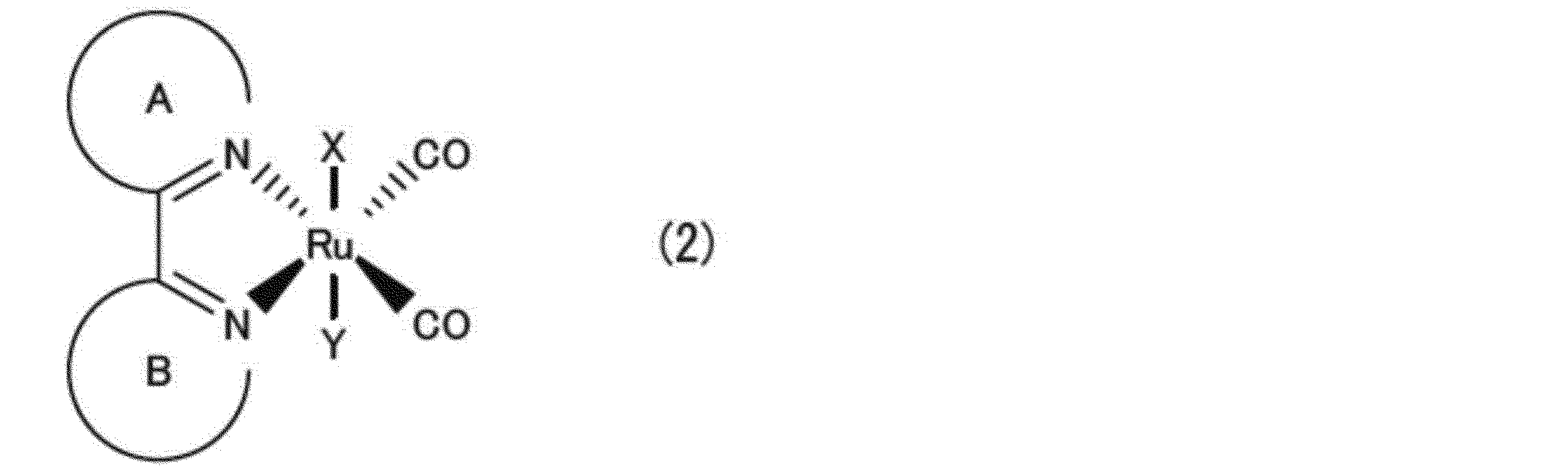
図1に示されるように、本開示の一実施形態に係る二酸化炭素吸収還元装置1は、上述した二酸化炭素吸収還元溶液2を収容する電気分解装置3を備えている。電気分解装置3内は、隔膜4により第1室3aと第2室3bとに区画されている。第1室3a内の二酸化炭素吸収還元溶液2に浸漬するように陰極5が設けられるとともに、第2室3b内の二酸化炭素吸収還元溶液2に浸漬するように陽極6が設けられている。陰極5及び陽極6はそれぞれ、直流電源7に電気的に接続されている。
次に、二酸化炭素吸収還元溶液2の動作(二酸化炭素吸収還元方法)を図1に基づいて説明する。吸収塔14にはガス供給ライン15を介して、二酸化炭素を含むガス、例えば図示しない燃焼設備から排出された燃焼ガスが供給される。吸収塔14に供給された燃焼ガスは吸収塔14内を上昇する。また、吸収塔14には流出ライン13を介して、吸収液としての二酸化炭素吸収還元溶液2が供給される。吸収塔14に供給された吸収液は吸収塔14内を落下する。吸収塔14内において、上昇する燃焼ガスと落下する吸収液とが気液接触することにより、燃焼ガスに含まれる二酸化炭素が吸収液に吸収され、二酸化炭素が除去された燃焼ガスは、ガス流出ライン16を介して吸収塔14から流出する。二酸化炭素を吸収した吸収液は吸収塔14内の下部に滞留するが、ポンプ17によって吸収塔14から吸収液が抜き出されて、供給ライン12を介して電気分解装置3の第1室3aに供給される。
CO2+H2O+2e-→CO+2OH- (A)
CO2+2H2O+2e-→HCOOH+2OH- (B)
2OH-→(1/2)O2+H2O+2e- (C)
水及び水溶性溶媒の混合溶媒中に0.01~100mMの金属錯体を含む二酸化炭素吸収還元溶液(2)であって、
前記金属錯体は、
レニウム、マンガン、又は鉄のいずれかである中心金属と、
前記中心金属に配位する配位子と
を含み、
前記配位子は、2つ以上のカルボニル基及び2つ以上の窒素原子含有複素環を含み、前記2つ以上の窒素原子含有複素環の少なくとも1つは、カルボキシ基又はヒドロキシ基を含む少なくとも1つの置換基を有する。
前記配位子は、2つ以上のカルボニル基及び2つ以上の窒素原子含有複素環を含み、前記2つ以上の窒素原子含有複素環の少なくとも1つは、少なくとも1つのヒドロキシメチル基又はヒドロキシエチル基又はカルボキシ基である。
水及び水溶性溶媒の混合溶媒中に0.01~100mMの金属錯体を含む二酸化炭素吸収還元溶液であって、
前記金属錯体は、
ルテニウムと、
ルテニウムに配位する配位子と
を含み、
前記配位子は、2つ以上のカルボニル基及び2つ以上の窒素原子含有複素環を含む。
前記水溶性溶媒は、水酸基を有する有機化合物を含む液体である。
前記有機化合物は、メチルアルコール、エチルアルコール、1-プロピルアルコール、又は2-プロピルアルコールである。
前記有機化合物はアルカノールアミンである。
前記混合溶媒は、無機炭酸塩、無機水酸化物又は無機塩を含む。
前記水溶性溶媒はアミノ酸を含む。
[1]~[8]のいずれかの二酸化炭素吸収還元溶液(2)を収容する電気分解装置(3)を備える。
二酸化炭素を吸収した前記二酸化炭素吸収還元溶液を電気分解装置(3)内に供給するための供給ライン(12)と、
前記電気分解装置(3)内から前記二酸化炭素吸収還元溶液(2)が流出する流出ライン(13)と
を備える。
二酸化炭素を含むガスと前記二酸化炭素吸収還元溶液とを接触させて該二酸化炭素吸収還元溶液に二酸化炭素を吸収させる吸収塔(14)をさらに備え、
前記吸収塔(14)で二酸化炭素を吸収した前記二酸化炭素吸収還元溶液は前記供給ライン(12)を介して前記電気分解装置(3)内に供給され、前記流出ライン(13)を介して前記電気分解装置(3)内から流出した前記二酸化炭素吸収還元溶液(2)は、前記吸収塔(14)に供給されて前記ガスと接触する。
二酸化炭素を含むガスから二酸化炭素を回収する二酸化炭素回収装置(20)と、
前記二酸化炭素回収装置(20)において回収された二酸化炭素を前記電気分解装置(3)に収容された前記二酸化炭素吸収還元溶液(2)に供給するガス供給ライン(26)と
を備える。
前記二酸化炭素回収装置(20)は、
二酸化炭素を含む前記ガスと吸収液とを接触させて該吸収液に二酸化炭素を吸収させる吸収塔(14)と、
二酸化炭素を吸収した前記吸収液から二酸化炭素を放出する再生塔(21)と
を備え、
前記再生塔(21)で放出された二酸化炭素は前記ガス供給ライン(26)を介して前記電気分解装置(3)に収容された前記二酸化炭素吸収還元溶液(2)に供給される。
[1]~[8]のいずれかの二酸化炭素吸収還元溶液(2)に二酸化炭素を供給するステップと、
二酸化炭素を供給された前記二酸化炭素吸収還元溶液(2)を電気分解するステップと
を含む。
前記二酸化炭素吸収還元溶液(2)を電気分解することにより一酸化炭素又はギ酸の少なくとも一方が生成される。
2 二酸化炭素吸収還元溶液
3 電気分解装置
12 供給ライン
13 流出ライン
14 吸収塔
20 二酸化炭素回収装置
21 再生塔
26 ガス供給ライン
Claims (15)
- 水及び水溶性溶媒の混合溶媒中に0.01~100mMの金属錯体を含む二酸化炭素吸収還元溶液であって、
前記金属錯体は、
レニウム、マンガン、又は鉄のいずれかである中心金属と、
前記中心金属に配位する配位子と
を含み、
前記配位子は、2つ以上のカルボニル基及び2つ以上の窒素原子含有複素環を含み、前記2つ以上の窒素原子含有複素環の少なくとも1つは、カルボキシ基又はヒドロキシ基を含む少なくとも1つの置換基を有する二酸化炭素吸収還元溶液。 - 前記配位子は、2つ以上のカルボニル基及び2つ以上の窒素原子含有複素環を含み、前記2つ以上の窒素原子含有複素環の少なくとも1つは、少なくとも1つのヒドロキシメチル基又はヒドロキシエチル基又はカルボキシ基である、請求項1に記載の二酸化炭素吸収還元溶液。
- 水及び水溶性溶媒の混合溶媒中に0.01~100mMの金属錯体を含む二酸化炭素吸収還元溶液であって、
前記金属錯体は、
ルテニウムと、
ルテニウムに配位する配位子と
を含み、
前記配位子は、2つ以上のカルボニル基及び2つ以上の窒素原子含有複素環を含む二酸化炭素吸収還元溶液。 - 前記水溶性溶媒は、水酸基を有する有機化合物を含む液体である、請求項1~3のいずれか一項に記載の二酸化炭素吸収還元溶液。
- 前記有機化合物は、メチルアルコール、エチルアルコール、1-プロピルアルコール、又は2-プロピルアルコールである、請求項4に記載の二酸化炭素吸収還元溶液。
- 前記有機化合物はアルカノールアミンである、請求項4に記載の二酸化炭素吸収還元溶液。
- 前記混合溶媒は、無機炭酸塩、無機水酸化物又は無機塩を含む、請求項1~3のいずれか一項に記載の二酸化炭素吸収還元溶液。
- 前記水溶性溶媒はアミノ酸を含む、請求項1~3のいずれか一項に記載の二酸化炭素吸収還元溶液。
- 請求項1~3のいずれか一項に記載の二酸化炭素吸収還元溶液を収容する電気分解装置を備える二酸化炭素吸収還元装置。
- 二酸化炭素を吸収した前記二酸化炭素吸収還元溶液を電気分解装置内に供給するための供給ラインと、
前記電気分解装置内から前記二酸化炭素吸収還元溶液が流出する流出ラインと
を備える、請求項9に記載の二酸化炭素吸収還元装置。 - 二酸化炭素を含むガスと前記二酸化炭素吸収還元溶液とを接触させて該二酸化炭素吸収還元溶液に二酸化炭素を吸収させる吸収塔をさらに備え、
前記吸収塔で二酸化炭素を吸収した前記二酸化炭素吸収還元溶液は前記供給ラインを介して前記電気分解装置内に供給され、前記流出ラインを介して前記電気分解装置内から流出した前記二酸化炭素吸収還元溶液は、前記吸収塔に供給されて前記ガスと接触する、請求項10に記載の二酸化炭素吸収還元装置。 - 二酸化炭素を含むガスから二酸化炭素を回収する二酸化炭素回収装置と、
前記二酸化炭素回収装置において回収された二酸化炭素を前記電気分解装置に収容された前記二酸化炭素吸収還元溶液に供給するガス供給ラインと
を備える、請求項9に記載の二酸化炭素吸収還元装置。 - 前記二酸化炭素回収装置は、
二酸化炭素を含む前記ガスと吸収液とを接触させて該吸収液に二酸化炭素を吸収させる吸収塔と、
二酸化炭素を吸収した前記吸収液から二酸化炭素を放出する再生塔と
を備え、
前記再生塔で放出された二酸化炭素は前記ガス供給ラインを介して前記電気分解装置に収容された前記二酸化炭素吸収還元溶液に供給される、請求項12に記載の二酸化炭素吸収還元装置。 - 請求項1~3のいずれか一項に記載の二酸化炭素吸収還元溶液に二酸化炭素を供給するステップと、
二酸化炭素を供給された前記二酸化炭素吸収還元溶液を電気分解するステップと
を含む二酸化炭素吸収還元方法。 - 前記二酸化炭素吸収還元溶液を電気分解することにより一酸化炭素又はギ酸の少なくとも一方が生成される、請求項14に記載の二酸化炭素吸収還元方法。
Priority Applications (4)
| Application Number | Priority Date | Filing Date | Title |
|---|---|---|---|
| AU2022333697A AU2022333697B2 (en) | 2021-08-26 | 2022-08-09 | Carbon dioxide absorption and reduction solution, carbon dioxide absorption and reduction device, and carbon dioxide absorption and reduction method |
| EP22861145.5A EP4349482A4 (en) | 2021-08-26 | 2022-08-09 | CARBON DIOXIDE ABSORPTION AND REDUCTION SOLUTION, CARBON DIOXIDE ABSORPTION AND REDUCTION DEVICE AND CARBON DIOXIDE ABSORPTION AND REDUCTION METHOD |
| US18/570,494 US20240293771A1 (en) | 2021-08-26 | 2022-08-09 | Carbon dioxide absorption and reduction solution, carbon dioxide absorption and reduction device, and carbon dioxide absorption and reduction method |
| CA3226753A CA3226753A1 (en) | 2021-08-26 | 2022-08-09 | Carbon dioxide absorption and reduction solution, carbon dioxide absorption and reduction device, and carbon dioxide absorption and reduction method |
Applications Claiming Priority (2)
| Application Number | Priority Date | Filing Date | Title |
|---|---|---|---|
| JP2021-137715 | 2021-08-26 | ||
| JP2021137715A JP7730500B2 (ja) | 2021-08-26 | 2021-08-26 | 二酸化炭素吸収還元溶液、二酸化炭素吸収還元装置、及び二酸化炭素吸収還元方法 |
Publications (1)
| Publication Number | Publication Date |
|---|---|
| WO2023026855A1 true WO2023026855A1 (ja) | 2023-03-02 |
Family
ID=85323176
Family Applications (1)
| Application Number | Title | Priority Date | Filing Date |
|---|---|---|---|
| PCT/JP2022/030439 Ceased WO2023026855A1 (ja) | 2021-08-26 | 2022-08-09 | 二酸化炭素吸収還元溶液、二酸化炭素吸収還元装置、及び二酸化炭素吸収還元方法 |
Country Status (6)
| Country | Link |
|---|---|
| US (1) | US20240293771A1 (ja) |
| EP (1) | EP4349482A4 (ja) |
| JP (1) | JP7730500B2 (ja) |
| AU (1) | AU2022333697B2 (ja) |
| CA (1) | CA3226753A1 (ja) |
| WO (1) | WO2023026855A1 (ja) |
Cited By (1)
| Publication number | Priority date | Publication date | Assignee | Title |
|---|---|---|---|---|
| WO2024185236A1 (ja) * | 2023-03-06 | 2024-09-12 | 三菱重工業株式会社 | 二酸化炭素吸収還元溶液、二酸化炭素吸収還元装置、及び二酸化炭素吸収還元方法 |
Citations (5)
| Publication number | Priority date | Publication date | Assignee | Title |
|---|---|---|---|---|
| JP2005040683A (ja) * | 2003-07-25 | 2005-02-17 | Kansai Electric Power Co Inc:The | 二酸化窒素と二酸化炭素の除去方法及びその装置 |
| WO2016136433A1 (ja) * | 2015-02-27 | 2016-09-01 | 国立研究開発法人科学技術振興機構 | 二酸化炭素の電気化学的還元 |
| JP2018510262A (ja) * | 2015-02-09 | 2018-04-12 | シーメンス アクチエンゲゼルシヤフトSiemens Aktiengesellschaft | 二酸化炭素の電気化学的利用のための還元方法及び電気分解システム |
| WO2018074443A1 (ja) * | 2016-10-19 | 2018-04-26 | 三菱重工業株式会社 | 二酸化炭素回収システム、火力発電設備、及び、二酸化炭素回収方法 |
| JP2021137715A (ja) | 2020-03-04 | 2021-09-16 | トーメイダイヤ株式会社 | ダイヤモンド基塊状工具素材及びその製造方法 |
Family Cites Families (3)
| Publication number | Priority date | Publication date | Assignee | Title |
|---|---|---|---|---|
| US20130277209A1 (en) * | 2010-12-28 | 2013-10-24 | Kabushiki Kaisha Toyota Chuo Kenkyusho | Photochemical reaction device |
| JP7330042B2 (ja) * | 2019-09-27 | 2023-08-21 | 三菱重工業株式会社 | 二酸化炭素還元システム及び二酸化炭素還元方法 |
| GB2602030A (en) * | 2020-12-15 | 2022-06-22 | Univ Liverpool | Improvements in electrochemical reduction of carbon dioxide |
-
2021
- 2021-08-26 JP JP2021137715A patent/JP7730500B2/ja active Active
-
2022
- 2022-08-09 EP EP22861145.5A patent/EP4349482A4/en active Pending
- 2022-08-09 AU AU2022333697A patent/AU2022333697B2/en active Active
- 2022-08-09 US US18/570,494 patent/US20240293771A1/en active Pending
- 2022-08-09 WO PCT/JP2022/030439 patent/WO2023026855A1/ja not_active Ceased
- 2022-08-09 CA CA3226753A patent/CA3226753A1/en active Pending
Patent Citations (6)
| Publication number | Priority date | Publication date | Assignee | Title |
|---|---|---|---|---|
| JP2005040683A (ja) * | 2003-07-25 | 2005-02-17 | Kansai Electric Power Co Inc:The | 二酸化窒素と二酸化炭素の除去方法及びその装置 |
| JP2018510262A (ja) * | 2015-02-09 | 2018-04-12 | シーメンス アクチエンゲゼルシヤフトSiemens Aktiengesellschaft | 二酸化炭素の電気化学的利用のための還元方法及び電気分解システム |
| WO2016136433A1 (ja) * | 2015-02-27 | 2016-09-01 | 国立研究開発法人科学技術振興機構 | 二酸化炭素の電気化学的還元 |
| JP6615175B2 (ja) | 2015-02-27 | 2019-12-04 | 国立研究開発法人科学技術振興機構 | 二酸化炭素の電気化学的還元 |
| WO2018074443A1 (ja) * | 2016-10-19 | 2018-04-26 | 三菱重工業株式会社 | 二酸化炭素回収システム、火力発電設備、及び、二酸化炭素回収方法 |
| JP2021137715A (ja) | 2020-03-04 | 2021-09-16 | トーメイダイヤ株式会社 | ダイヤモンド基塊状工具素材及びその製造方法 |
Non-Patent Citations (3)
| Title |
|---|
| A. NAKADA ET AL.: "Selective Electrocatalysis of a Water-Soluble Rhenium(I) Complex for CO Reduction Using Water As an Electron Donor", ACS. CATAL., vol. 8, 2018, pages 354 - 363, XP093039942, DOI: 10.1021/acscatal.7b03275 |
| NAKADA AKINOBU, ISHITANI OSAMU: "Selective Electrocatalysis of a Water-Soluble Rhenium(I) Complex for CO 2 Reduction Using Water As an Electron Donor", ACS CATALYSIS, AMERICAN CHEMICAL SOCIETY, US, vol. 8, no. 1, 5 January 2018 (2018-01-05), US , pages 354 - 363, XP093039942, ISSN: 2155-5435, DOI: 10.1021/acscatal.7b03275 * |
| WALSH JAMES J., NERI GAIA, SMITH CHARLOTTE L., COWAN ALEXANDER J.: "Water-Soluble Manganese Complex for Selective Electrocatalytic CO 2 Reduction to CO", ORGANOMETALLICS, AMERICAN CHEMICAL SOCIETY, vol. 38, no. 6, 25 March 2019 (2019-03-25), pages 1224 - 1229, XP093039944, ISSN: 0276-7333, DOI: 10.1021/acs.organomet.8b00336 * |
Cited By (1)
| Publication number | Priority date | Publication date | Assignee | Title |
|---|---|---|---|---|
| WO2024185236A1 (ja) * | 2023-03-06 | 2024-09-12 | 三菱重工業株式会社 | 二酸化炭素吸収還元溶液、二酸化炭素吸収還元装置、及び二酸化炭素吸収還元方法 |
Also Published As
| Publication number | Publication date |
|---|---|
| JP2023031928A (ja) | 2023-03-09 |
| EP4349482A1 (en) | 2024-04-10 |
| EP4349482A4 (en) | 2025-03-05 |
| US20240293771A1 (en) | 2024-09-05 |
| AU2022333697A1 (en) | 2024-01-04 |
| JP7730500B2 (ja) | 2025-08-28 |
| CA3226753A1 (en) | 2023-03-02 |
| AU2022333697B2 (en) | 2025-08-28 |
Similar Documents
| Publication | Publication Date | Title |
|---|---|---|
| EP3752660B1 (en) | Integrated electrochemical capture and conversion of carbon dioxide | |
| RU2479558C2 (ru) | Электрохимический способ получения азотных удобрений | |
| JP2021516290A (ja) | 二酸化炭素を電気化学還元する方法 | |
| US20140183038A1 (en) | Carbon Dioxide Capture and Conversion to Organic Products | |
| CN107250438A (zh) | 用于二氧化碳利用的方法和电解系统 | |
| JPWO2012077198A1 (ja) | 燃料製造システム | |
| CN118127543A (zh) | 集成式二氧化碳捕集与转化利用制备合成气的系统与方法 | |
| KR20250028387A (ko) | 수소 생산을 결합한 탄소 포집 방법 및 장치 | |
| Lhostis et al. | Promoting selective CO2 electroreduction to formic acid in acidic medium with low potassium concentrations under high CO2 pressure | |
| WO2023026855A1 (ja) | 二酸化炭素吸収還元溶液、二酸化炭素吸収還元装置、及び二酸化炭素吸収還元方法 | |
| Yang et al. | Integrated Strategies Toward the Capture and Electrochemical Conversion of Low‐Concentration Carbon Dioxide | |
| US20230002221A1 (en) | Hydrogen storage method, hydrogen gas production method and hydrogen gas production system | |
| WO2022227146A1 (zh) | 用于捕获并电解二氧化碳的组合物以及方法 | |
| WO2018027322A1 (en) | Electrochemical carbon dioxide utilization | |
| JP2006176879A (ja) | 電解水素製造法のための電解質組成物方法 | |
| WO2024185236A1 (ja) | 二酸化炭素吸収還元溶液、二酸化炭素吸収還元装置、及び二酸化炭素吸収還元方法 | |
| WO2024048405A1 (ja) | 二酸化炭素吸収還元溶液、二酸化炭素吸収還元装置、及び二酸化炭素吸収還元方法 | |
| CN116113624A (zh) | 生产环氧乙烷的方法 | |
| KR102675741B1 (ko) | 알킬렌 카보네이트의 전기화학적 합성 방법 | |
| EP4502236A1 (en) | Carbon dioxide conversion system | |
| Widiatmoko et al. | Optimizing Reactor Configuration and Electrode Geometry for Enhanced Electrochemical Reduction of CO 2. | |
| CN116637479A (zh) | 一种二氧化碳捕集及利用系统和方法 | |
| KR20260037454A (ko) | 전해액 순환을 이용한 암모니아의 전기분해 방법 | |
| WO2022217313A1 (en) | Decarbonisation system and process | |
| CN114430057A (zh) | 制氢系统以及使用该制氢系统的制氢方法和动力系统 |
Legal Events
| Date | Code | Title | Description |
|---|---|---|---|
| 121 | Ep: the epo has been informed by wipo that ep was designated in this application |
Ref document number: 22861145 Country of ref document: EP Kind code of ref document: A1 |
|
| WWE | Wipo information: entry into national phase |
Ref document number: 202317084184 Country of ref document: IN Ref document number: 2022333697 Country of ref document: AU Ref document number: AU2022333697 Country of ref document: AU |
|
| WWE | Wipo information: entry into national phase |
Ref document number: 18570494 Country of ref document: US |
|
| ENP | Entry into the national phase |
Ref document number: 2022333697 Country of ref document: AU Date of ref document: 20220809 Kind code of ref document: A |
|
| WWE | Wipo information: entry into national phase |
Ref document number: 2022861145 Country of ref document: EP |
|
| ENP | Entry into the national phase |
Ref document number: 2022861145 Country of ref document: EP Effective date: 20240105 |
|
| WWE | Wipo information: entry into national phase |
Ref document number: 3226753 Country of ref document: CA |
|
| NENP | Non-entry into the national phase |
Ref country code: DE |