WO2023027556A1 - 셀 커버리지 확장 방법 및 이를 위한 장치 - Google Patents
셀 커버리지 확장 방법 및 이를 위한 장치 Download PDFInfo
- Publication number
- WO2023027556A1 WO2023027556A1 PCT/KR2022/012830 KR2022012830W WO2023027556A1 WO 2023027556 A1 WO2023027556 A1 WO 2023027556A1 KR 2022012830 W KR2022012830 W KR 2022012830W WO 2023027556 A1 WO2023027556 A1 WO 2023027556A1
- Authority
- WO
- WIPO (PCT)
- Prior art keywords
- signal
- base station
- information
- access link
- backhaul
- Prior art date
- Legal status (The legal status is an assumption and is not a legal conclusion. Google has not performed a legal analysis and makes no representation as to the accuracy of the status listed.)
- Ceased
Links
Images







Classifications
-
- H—ELECTRICITY
- H04—ELECTRIC COMMUNICATION TECHNIQUE
- H04B—TRANSMISSION
- H04B7/00—Radio transmission systems, i.e. using radiation field
- H04B7/02—Diversity systems; Multi-antenna system, i.e. transmission or reception using multiple antennas
- H04B7/04—Diversity systems; Multi-antenna system, i.e. transmission or reception using multiple antennas using two or more spaced independent antennas
- H04B7/06—Diversity systems; Multi-antenna system, i.e. transmission or reception using multiple antennas using two or more spaced independent antennas at the transmitting station
- H04B7/0686—Hybrid systems, i.e. switching and simultaneous transmission
- H04B7/0695—Hybrid systems, i.e. switching and simultaneous transmission using beam selection
- H04B7/06952—Selecting one or more beams from a plurality of beams, e.g. beam training, management or sweeping
- H04B7/06968—Selecting one or more beams from a plurality of beams, e.g. beam training, management or sweeping using quasi-colocation [QCL] between signals
-
- H—ELECTRICITY
- H04—ELECTRIC COMMUNICATION TECHNIQUE
- H04B—TRANSMISSION
- H04B7/00—Radio transmission systems, i.e. using radiation field
- H04B7/02—Diversity systems; Multi-antenna system, i.e. transmission or reception using multiple antennas
- H04B7/04—Diversity systems; Multi-antenna system, i.e. transmission or reception using multiple antennas using two or more spaced independent antennas
- H04B7/04013—Intelligent reflective surfaces
-
- H—ELECTRICITY
- H04—ELECTRIC COMMUNICATION TECHNIQUE
- H04B—TRANSMISSION
- H04B7/00—Radio transmission systems, i.e. using radiation field
- H04B7/02—Diversity systems; Multi-antenna system, i.e. transmission or reception using multiple antennas
- H04B7/04—Diversity systems; Multi-antenna system, i.e. transmission or reception using multiple antennas using two or more spaced independent antennas
- H04B7/0413—MIMO systems
- H04B7/0456—Selection of precoding matrices or codebooks, e.g. using matrices antenna weighting
-
- H—ELECTRICITY
- H04—ELECTRIC COMMUNICATION TECHNIQUE
- H04B—TRANSMISSION
- H04B7/00—Radio transmission systems, i.e. using radiation field
- H04B7/02—Diversity systems; Multi-antenna system, i.e. transmission or reception using multiple antennas
- H04B7/04—Diversity systems; Multi-antenna system, i.e. transmission or reception using multiple antennas using two or more spaced independent antennas
- H04B7/06—Diversity systems; Multi-antenna system, i.e. transmission or reception using multiple antennas using two or more spaced independent antennas at the transmitting station
- H04B7/0613—Diversity systems; Multi-antenna system, i.e. transmission or reception using multiple antennas using two or more spaced independent antennas at the transmitting station using simultaneous transmission
- H04B7/0615—Diversity systems; Multi-antenna system, i.e. transmission or reception using multiple antennas using two or more spaced independent antennas at the transmitting station using simultaneous transmission of weighted versions of same signal
- H04B7/0617—Diversity systems; Multi-antenna system, i.e. transmission or reception using multiple antennas using two or more spaced independent antennas at the transmitting station using simultaneous transmission of weighted versions of same signal for beam forming
-
- H—ELECTRICITY
- H04—ELECTRIC COMMUNICATION TECHNIQUE
- H04B—TRANSMISSION
- H04B7/00—Radio transmission systems, i.e. using radiation field
- H04B7/02—Diversity systems; Multi-antenna system, i.e. transmission or reception using multiple antennas
- H04B7/04—Diversity systems; Multi-antenna system, i.e. transmission or reception using multiple antennas using two or more spaced independent antennas
- H04B7/06—Diversity systems; Multi-antenna system, i.e. transmission or reception using multiple antennas using two or more spaced independent antennas at the transmitting station
- H04B7/0613—Diversity systems; Multi-antenna system, i.e. transmission or reception using multiple antennas using two or more spaced independent antennas at the transmitting station using simultaneous transmission
- H04B7/0682—Diversity systems; Multi-antenna system, i.e. transmission or reception using multiple antennas using two or more spaced independent antennas at the transmitting station using simultaneous transmission using phase diversity (e.g. phase sweeping)
-
- H—ELECTRICITY
- H04—ELECTRIC COMMUNICATION TECHNIQUE
- H04B—TRANSMISSION
- H04B7/00—Radio transmission systems, i.e. using radiation field
- H04B7/02—Diversity systems; Multi-antenna system, i.e. transmission or reception using multiple antennas
- H04B7/04—Diversity systems; Multi-antenna system, i.e. transmission or reception using multiple antennas using two or more spaced independent antennas
- H04B7/06—Diversity systems; Multi-antenna system, i.e. transmission or reception using multiple antennas using two or more spaced independent antennas at the transmitting station
- H04B7/0686—Hybrid systems, i.e. switching and simultaneous transmission
- H04B7/0695—Hybrid systems, i.e. switching and simultaneous transmission using beam selection
-
- H—ELECTRICITY
- H04—ELECTRIC COMMUNICATION TECHNIQUE
- H04B—TRANSMISSION
- H04B7/00—Radio transmission systems, i.e. using radiation field
- H04B7/02—Diversity systems; Multi-antenna system, i.e. transmission or reception using multiple antennas
- H04B7/04—Diversity systems; Multi-antenna system, i.e. transmission or reception using multiple antennas using two or more spaced independent antennas
- H04B7/06—Diversity systems; Multi-antenna system, i.e. transmission or reception using multiple antennas using two or more spaced independent antennas at the transmitting station
- H04B7/0686—Hybrid systems, i.e. switching and simultaneous transmission
- H04B7/0695—Hybrid systems, i.e. switching and simultaneous transmission using beam selection
- H04B7/06952—Selecting one or more beams from a plurality of beams, e.g. beam training, management or sweeping
-
- H—ELECTRICITY
- H04—ELECTRIC COMMUNICATION TECHNIQUE
- H04B—TRANSMISSION
- H04B7/00—Radio transmission systems, i.e. using radiation field
- H04B7/02—Diversity systems; Multi-antenna system, i.e. transmission or reception using multiple antennas
- H04B7/04—Diversity systems; Multi-antenna system, i.e. transmission or reception using multiple antennas using two or more spaced independent antennas
- H04B7/08—Diversity systems; Multi-antenna system, i.e. transmission or reception using multiple antennas using two or more spaced independent antennas at the receiving station
- H04B7/0837—Diversity systems; Multi-antenna system, i.e. transmission or reception using multiple antennas using two or more spaced independent antennas at the receiving station using pre-detection combining
- H04B7/0842—Weighted combining
- H04B7/086—Weighted combining using weights depending on external parameters, e.g. direction of arrival [DOA], predetermined weights or beamforming
-
- H—ELECTRICITY
- H04—ELECTRIC COMMUNICATION TECHNIQUE
- H04B—TRANSMISSION
- H04B7/00—Radio transmission systems, i.e. using radiation field
- H04B7/02—Diversity systems; Multi-antenna system, i.e. transmission or reception using multiple antennas
- H04B7/04—Diversity systems; Multi-antenna system, i.e. transmission or reception using multiple antennas using two or more spaced independent antennas
- H04B7/08—Diversity systems; Multi-antenna system, i.e. transmission or reception using multiple antennas using two or more spaced independent antennas at the receiving station
- H04B7/0868—Hybrid systems, i.e. switching and combining
- H04B7/088—Hybrid systems, i.e. switching and combining using beam selection
-
- H—ELECTRICITY
- H04—ELECTRIC COMMUNICATION TECHNIQUE
- H04B—TRANSMISSION
- H04B7/00—Radio transmission systems, i.e. using radiation field
- H04B7/14—Relay systems
- H04B7/15—Active relay systems
- H04B7/155—Ground-based stations
- H04B7/15528—Control of operation parameters of a relay station to exploit the physical medium
-
- H—ELECTRICITY
- H04—ELECTRIC COMMUNICATION TECHNIQUE
- H04W—WIRELESS COMMUNICATION NETWORKS
- H04W16/00—Network planning, e.g. coverage or traffic planning tools; Network deployment, e.g. resource partitioning or cells structures
- H04W16/24—Cell structures
- H04W16/26—Cell enhancers or enhancement, e.g. for tunnels, building shadow
-
- H—ELECTRICITY
- H04—ELECTRIC COMMUNICATION TECHNIQUE
- H04W—WIRELESS COMMUNICATION NETWORKS
- H04W16/00—Network planning, e.g. coverage or traffic planning tools; Network deployment, e.g. resource partitioning or cells structures
- H04W16/24—Cell structures
- H04W16/28—Cell structures using beam steering
-
- H—ELECTRICITY
- H04—ELECTRIC COMMUNICATION TECHNIQUE
- H04W—WIRELESS COMMUNICATION NETWORKS
- H04W72/00—Local resource management
- H04W72/04—Wireless resource allocation
- H04W72/044—Wireless resource allocation based on the type of the allocated resource
- H04W72/0446—Resources in time domain, e.g. slots or frames
Definitions
- the present invention relates to a method for extending cell coverage in a mobile communication system, and more particularly, to methods and devices for extending cell coverage using a relay node or an intelligent reflecting surface in a mobile communication system. it's about
- the NR communication system may support a frequency band up to around 100 GHz as well as a frequency band of 6 GHz or less, and compared to a conventional communication system (eg, a long-term evolution (LTE) communication system) More diverse services and scenarios can be supported.
- a usage scenario of the NR communication system may include enhanced mobile broadband (eMBB), ultra reliable low latency communication (URLLC), and massive machine type communication (mMTC).
- eMBB enhanced mobile broadband
- URLLC ultra reliable low latency communication
- mMTC massive machine type communication
- the 6G communication system being discussed recently is expected to enable more diverse services and user experiences by utilizing THz frequency band, artificial intelligence, satellite communication, and quantum technology.
- these communication systems must satisfy, and advanced communication technology is required to achieve them.
- An object of the present invention to solve the above problems is to provide a cell coverage extension method using a repeater or an intelligent reflective surface.
- Another object of the present invention to solve the above problems is to provide a configuration of devices for performing the method.
- An embodiment of the present invention for achieving the above object is a method of operating a repeater in a mobile communication system, comprising: receiving information about a backhaul reception beam and/or a backhaul transmission beam from a base station; Receive information on the access link transmission beam and/or access link reception beam from the base station, or obtain information on the access link transmission beam and/or access link reception beam from the backhaul reception beam and/or information on the backhaul transmission beam.
- the beam is a beam for the repeater to receive a signal from the base station
- the backhaul transmit beam is a beam for the repeater to transmit a signal to the base station
- the access link transmit beam is a beam for the repeater to transmit a signal to the terminal.
- the access link reception beam may be a beam for the terminal to receive a signal from the repeater.
- Information on the backhaul reception beam may be indicated based on a QCL source signal having a quasi-co-location (QCL) relationship with a downlink signal transmitted from the base station to the repeater and a QCL parameter for which the QCL relationship is established.
- QCL quasi-co-location
- the information on the backhaul transmission beam has a quasi-co-location (QCL) relationship or spatial relation with an uplink signal transmitted from the repeater to the base station or a downlink signal transmitted from the base station to the repeater. It may be indicated based on a source signal and a QCL parameter for which the QCL relationship or spatial relationship is established.
- QCL quasi-co-location
- the information on the access link transmission beam may be indicated based on a codebook including entry(s) in which each entry corresponds to a precoder applied to a signal transmitted to the terminal through the access link with the terminal.
- At least a part of the codebook is preset in the relay or received from the base station, and information on the access link transmission beam may be indicated by index (s) indicating at least one entry belonging to the codebook.
- the information on the access link reception beam may be indicated based on a codebook including entry(s) in which each entry corresponds to a reception filter applied to a signal received from the terminal through the access link with the terminal.
- At least a part of the codebook is preset in the relay or received from the base station, and information on the access link reception beam may be indicated by index (s) indicating at least one entry belonging to the codebook.
- the repeater is configured as an intelligent reflecting surface (IRS), and information about the backhaul transmission beam and/or information about the access link transmission beam is a phase shift value for a plurality of phase control elements constituting the IRS. values) may be included.
- IRS intelligent reflecting surface
- the backhaul transmission beam and/or the access link transmission beam may be formed by beamforming by the phase control elements.
- Another embodiment of the present invention to achieve the above object is in a mobile communication system.
- a method of operating a base station comprising: transmitting information about a backhaul receive beam and/or a backhaul transmit beam to a repeater; transmitting information about an access link transmit beam and/or an access link receive beam to the repeater; performing, by the repeater, communication with the repeater using the backhaul receive beam and/or the backhaul transmit beam formed using information about the backhaul receive beam and/or the backhaul transmit beam; and causing the relay to perform communication with a terminal using the access link transmission beam and/or the access link reception beam formed using information about the access link transmission beam and/or the access link reception beam;
- the backhaul reception beam is a beam for the repeater to receive a signal from the base station
- the backhaul transmission beam is a beam for the repeater to transmit a signal to the base station
- Information on the backhaul reception beam may be indicated based on a QCL source signal having a quasi-co-location (QCL) relationship with a downlink signal transmitted from the base station to the repeater and a QCL parameter for which the QCL relationship is established.
- QCL quasi-co-location
- the information on the backhaul transmission beam is a source having a quasi-co-location (QCL) or spatial relation with an uplink signal transmitted from the repeater to the base station or a downlink signal transmitted from the base station to the repeater. It may be indicated based on a signal and a QCL parameter for which the QCL relationship or spatial relationship is established.
- QCL quasi-co-location
- the information on the access link transmission beam belongs to a codebook including entry(s) in which each entry corresponds to a precoder applied to a signal transmitted from the repeater to the terminal through the access link with the terminal. It may be indicated by index(s) indicating at least one entry.
- the information on the access link reception beam belongs to a codebook in which each entry includes entry(s) corresponding to a reception filter applied to a signal received from the terminal through the access link with the terminal. It can be indicated by index(s) indicating one entry.
- the information about the backhaul transmission beam and/or the information about the access link transmission beam is a phase shift value for a plurality of phase control elements constituting the IRS. values) may be included.
- One embodiment of the present invention for achieving the above other object is, as a repeater, a processor; at least one transceiver coupled to the processor; and a memory storing at least one instruction executed by the processor, wherein when executed by the processor, the at least one instruction causes the repeater to: receive a backhaul receive beam from a base station via the at least one transceiver and/or or receiving information about a backhaul transmit beam; Information on the access link transmission beam and/or access link reception beam is received from the base station through the at least one transceiver, or from the information on the backhaul reception beam and/or backhaul transmission beam, the access link transmission beam and/or the access link obtaining information about a receive beam; performing communication with the base station through the at least one transceiver using the backhaul reception beam and/or the backhaul transmission beam formed using information about the backhaul reception beam and/or the backhaul transmission beam; and performing communication with a terminal through the at least one transceiver using the access link transmission beam and/or
- the backhaul reception beam is a beam for the repeater to receive a signal from the base station
- the backhaul transmission beam is a beam for the repeater to transmit a signal to the base station
- the access link transmission beam is the The repeater may be a beam for transmitting a signal to the terminal
- the access link reception beam may be a beam for the terminal to receive a signal from the repeater.
- Information on the backhaul reception beam may be indicated based on a QCL source signal having a quasi-co-location (QCL) relationship with a downlink signal transmitted from the base station to the repeater and a QCL parameter for which the QCL relationship is established.
- QCL quasi-co-location
- the information on the backhaul transmission beam has a quasi-co-location (QCL) relationship or spatial relation with an uplink signal transmitted from the repeater to the base station or a downlink signal transmitted from the base station to the repeater. It may be indicated based on a source signal and a QCL parameter for which the QCL relationship or spatial relationship is established.
- QCL quasi-co-location
- the information on the access link transmission beam may be indicated based on a codebook including entry(s) in which each entry corresponds to a precoder applied to a signal transmitted to the terminal through the access link with the terminal.
- the information on the access link reception beam may be indicated based on a codebook including entry(s) in which each entry corresponds to a reception filter applied to a signal received from the terminal through the access link with the terminal.
- a cell coverage extension method using a repeater or an intelligent reflection surface (IRS) may be provided. Accordingly, the performance of the communication system can be improved.
- FIG. 1 is a conceptual diagram illustrating a first embodiment of a communication system.
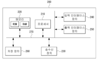
- Figure 2 is a block diagram showing a first embodiment of a device.
- FIG. 3 is a conceptual diagram illustrating a first embodiment of a beamforming operation method using a repeater.
- 4A is a conceptual diagram illustrating a first embodiment of a beamforming operation method using IRS.
- 4B is a conceptual diagram illustrating a second embodiment of a beamforming operation method using IRS.
- FIG. 5 is a conceptual diagram illustrating a first embodiment of a beamforming operation method of a relay node for beam management of a terminal.
- FIG. 6 is a conceptual diagram illustrating a second embodiment of a beamforming operation method of a relay node for beam management of a terminal.
- FIGS. 7A and 7B are conceptual diagrams illustrating a first embodiment of multi-beam-based SSB transmission and SSB resource allocation.
- 8A is a conceptual diagram illustrating a first embodiment of a method of indicating an access link beam of a relay node.
- 8B is a conceptual diagram illustrating a second embodiment of a method of indicating an access link beam of a relay node.
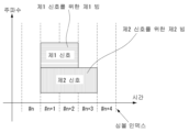
- FIG. 9 is a conceptual diagram illustrating a first embodiment of a method for determining transmission timing of a relay node.
- first and second may be used to describe various components, but the components should not be limited by the terms. These terms are only used for the purpose of distinguishing one component from another. For example, a first element may be termed a second element, and similarly, a second element may be termed a first element, without departing from the scope of the present invention.
- the term "and/or" includes any combination of a plurality of related listed items or any of a plurality of related listed items.
- “at least one of A and B” may mean “at least one of A or B” or “at least one of combinations of one or more of A and B”. Also, in the embodiments of the present application, “one or more of A and B” may mean “one or more of A or B” or “one or more of combinations of one or more of A and B”.
- the communication system may be a 4G communication system (eg, a long-term evolution (LTE) communication system, an LTE-A communication system), a 5G communication system (eg, a new radio (NR) communication system), a 6G communication system, and the like.
- the 4G communication system can support communication in a frequency band of 6 GHz or less
- the 5G communication system can support communication in a frequency band of 6 GHz or more as well as a frequency band of 6 GHz or less.
- a communication system to which embodiments according to the present invention are applied is not limited to the contents described below, and embodiments according to the present invention can be applied to various communication systems.
- the communication system may be used in the same sense as a communication network, "LTE” may indicate “4G communication system", “LTE communication system” or “LTE-A communication system”, and "NR” may indicate "5G communication system” or "NR communication system”.
- setting an operation means “setting information for the corresponding operation (eg, information element, parameter)” and/or “performing the corresponding operation”. It may mean that the "instructing information” is signaled.
- Setting an information element eg, parameter
- Configuring a resource eg, a resource region
- configuration information of a corresponding resource is signaled.
- SI system information
- SIB system information block
- MIB master information block
- RRC Radio Resource Control
- CE MAC control element
- PHY PHY signaling
- DCI downlink control information
- UCI uplink control information
- SCI sidelink control information
- FIG. 1 is a conceptual diagram illustrating a first embodiment of a communication system.
- a communication system 100 includes a plurality of communication nodes 110-1, 110-2, 110-3, 120-1, 120-2, 130-1, 130-2, 130-3, 130-4, 130-5, 130-6).
- the communication system 100 includes a core network (eg, a serving-gateway (S-GW), a packet data network (PDN)-gateway (P-GW), and a mobility management entity (MME)).
- S-GW serving-gateway
- PDN packet data network
- MME mobility management entity
- the core network includes an access and mobility management function (AMF), a user plane function (UPF), a session management function (SMF), and the like.
- AMF access and mobility management function
- UPF user plane function
- SMF session management function
- the plurality of communication nodes 110 to 130 may support communication protocols (eg, LTE communication protocol, LTE-A communication protocol, NR communication protocol, etc.) defined in the 3rd generation partnership project (3GPP) standard.
- the plurality of communication nodes 110 to 130 are CDMA (code division multiple access) technology, WCDMA (wideband CDMA) technology, TDMA (time division multiple access) technology, FDMA (frequency division multiple access) technology, OFDM (orthogonal frequency division) multiplexing) technology, filtered OFDM technology, CP (cyclic prefix)-OFDM technology, DFT-s-OFDM (discrete Fourier transform-spread-OFDM) technology, OFDMA (orthogonal frequency division multiple access) technology, SC (single carrier)-FDMA technology, NOMA (Non-orthogonal Multiple Access) technology, GFDM (generalized frequency division multiplexing) technology, FBMC (filter bank multi-carrier) technology, UFMC (universal filtered multi-carrier) technology,
- Figure 2 is a block diagram showing a first embodiment of a device.
- an apparatus 200 may include at least one processor 210, a memory 220, and a transceiver 230 connected to a network to perform communication.
- the device 200 may further include an input interface device 240 , an output interface device 250 , a storage device 260 , and the like.
- Each component included in the device 200 may be connected by a bus 270 to communicate with each other.
- the processor 210 may execute a program command stored in at least one of the memory 220 and the storage device 260 .
- the processor 210 may refer to a central processing unit (CPU), a graphics processing unit (GPU), or a dedicated processor on which methods according to embodiments of the present invention are performed.
- Each of the memory 220 and the storage device 260 may include at least one of a volatile storage medium and a non-volatile storage medium.
- the memory 220 may include at least one of a read only memory (ROM) and a random access memory (RAM).
- the communication system 100 includes a plurality of base stations (110-1, 110-2, 110-3, 120-1, 120-2), a plurality of terminals 130- 1, 130-2, 130-3, 130-4, 130-5, 130-6).
- Each of the first base station 110-1, the second base station 110-2, and the third base station 110-3 may form a macro cell.
- Each of the fourth base station 120-1 and the fifth base station 120-2 may form a small cell.
- the fourth base station 120-1, the third terminal 130-3, and the fourth terminal 130-4 may belong to the cell coverage of the first base station 110-1.
- the second terminal 130-2, the fourth terminal 130-4, and the fifth terminal 130-5 may belong to the cell coverage of the second base station 110-2.
- the fifth base station 120-2, the fourth terminal 130-4, the fifth terminal 130-5, and the sixth terminal 130-6 may belong to the cell coverage of the third base station 110-3. There is.
- the first terminal 130-1 may belong to the cell coverage of the fourth base station 120-1.
- the sixth terminal 130-6 may belong to the cell coverage of the fifth base station 120-2.
- each of the plurality of base stations 110-1, 110-2, 110-3, 120-1, and 120-2 is a NodeB (NB), an evolved NodeB (eNB), a gNB, an advanced base station (ABS), and a HR -BS (high reliability-base station), BTS (base transceiver station), radio base station, radio transceiver, access point, access node, radio access station (RAS) ), MMR-BS (mobile multihop relay-base station), RS (relay station), ARS (advanced relay station), HR-RS (high reliability-relay station), HNB (home NodeB), HeNB (home eNodeB), It may be referred to as a road side unit (RSU), a radio remote head (RRH), a transmission point (TP), a transmission and reception point (TRP), and the like.
- RSU road side unit
- RRH radio remote head
- TP transmission point
- TRP transmission and reception point
- Each of the plurality of terminals 130-1, 130-2, 130-3, 130-4, 130-5, and 130-6 includes user equipment (UE), terminal equipment (TE), advanced mobile station (AMS), HR-MS (high reliability-mobile station), terminal, access terminal, mobile terminal, station, subscriber station, mobile station, mobile It may be referred to as a portable subscriber station, a node, a device, an on board unit (OBU), and the like.
- UE user equipment
- TE terminal equipment
- AMS advanced mobile station
- HR-MS high reliability-mobile station
- each of the plurality of base stations 110-1, 110-2, 110-3, 120-1, and 120-2 may operate in different frequency bands or may operate in the same frequency band.
- Each of the plurality of base stations 110-1, 110-2, 110-3, 120-1, and 120-2 may be connected to each other through an ideal backhaul link or a non-ideal backhaul link, and , information can be exchanged with each other through an ideal backhaul link or a non-ideal backhaul link.
- Each of the plurality of base stations 110-1, 110-2, 110-3, 120-1, and 120-2 may be connected to the core network through an ideal backhaul link or a non-ideal backhaul link.
- Each of the plurality of base stations 110-1, 110-2, 110-3, 120-1, and 120-2 transmits a signal received from the core network to a corresponding terminal 130-1, 130-2, 130-3, and 130 -4, 130-5, 130-6), and signals received from corresponding terminals 130-1, 130-2, 130-3, 130-4, 130-5, 130-6 are transmitted to the core network can be sent to
- each of the plurality of base stations 110-1, 110-2, 110-3, 120-1, and 120-2 transmits MIMO (eg, single user (SU)-MIMO, multi-user (MU)- MIMO, massive MIMO, etc.), coordinated multipoint (CoMP) transmission, carrier aggregation (CA) transmission, transmission in an unlicensed band, direct communication between devices (device to device communication, D2D) (or , proximity services (ProSe)), Internet of Things (IoT) communication, dual connectivity (DC), etc. may be supported.
- MIMO eg, single user (SU)-MIMO, multi-user (MU)- MIMO, massive MIMO, etc.
- CoMP coordinated multipoint
- CA carrier aggregation
- D2D direct communication between devices (device to device communication, D2D) (or , proximity services (ProSe)), Internet of Things (IoT) communication, dual connectivity (DC), etc.
- each of the plurality of terminals 130-1, 130-2, 130-3, 130-4, 130-5, and 130-6 is a base station 110-1, 110-2, 110-3, 120-1 , 120-2) and operations supported by the base stations 110-1, 110-2, 110-3, 120-1, and 120-2 may be performed.
- the second base station 110-2 can transmit a signal to the fourth terminal 130-4 based on the SU-MIMO scheme, and the fourth terminal 130-4 uses the SU-MIMO scheme.
- a signal may be received from the second base station 110-2.
- the second base station 110-2 may transmit a signal to the fourth terminal 130-4 and the fifth terminal 130-5 based on the MU-MIMO scheme, and the fourth terminal 130-4 And each of the fifth terminal 130-5 may receive a signal from the second base station 110-2 by the MU-MIMO method.
- Each of the first base station 110-1, the second base station 110-2, and the third base station 110-3 may transmit a signal to the fourth terminal 130-4 based on the CoMP scheme, and The terminal 130-4 may receive signals from the first base station 110-1, the second base station 110-2, and the third base station 110-3 by CoMP.
- Each of the plurality of base stations 110-1, 110-2, 110-3, 120-1, and 120-2 includes a terminal 130-1, 130-2, 130-3, and 130-4 belonging to its own cell coverage. , 130-5, 130-6) and a CA method.
- Each of the first base station 110-1, the second base station 110-2, and the third base station 110-3 controls D2D between the fourth terminal 130-4 and the fifth terminal 130-5. and each of the fourth terminal 130-4 and the fifth terminal 130-5 may perform D2D under the control of the second base station 110-2 and the third base station 110-3, respectively. .
- the present invention relates to a method for extending cell coverage using a relay node in a communication system, and specifically includes a method for a base station to control a relay node and a method for operating the relay node accordingly.
- the following embodiments can be applied to an NR communication system, and can also be applied to other communication systems (eg, LTE communication system, 5G (fifth generation) communication system, 6G (sixth generation) communication system, etc.) in addition to the NR communication system.
- Numerology applied to physical signals and channels in a communication system may be variable.
- the numerology can be varied to meet the various technical requirements of a communication system.
- the numerology may include a subcarrier interval and a CP length (or CP type).
- Table 1 may be a first embodiment of a numerology configuration method for a CP-OFDM based communication system. Adjacent subcarrier intervals may have an exponential multiplication of 2 with each other, and the CP length may be scaled by the same ratio as the OFDM symbol length.
- numerologies of Table 1 may be supported according to the frequency band in which the communication system operates.
- numerology(s) not listed in Table 1 may be further supported in the communication system.
- CP type(s) eg, extended CP not listed in Table 1 may be additionally supported.
- Table 1 relates to a first embodiment of a numerology configuration method for a CP-OFDM based communication system.
- Elements constituting a frame structure in the time domain may include subframes, slots, mini-slots, symbols, and the like.
- a subframe may be used as a unit of transmission or measurement, and the length of a subframe may have a fixed value (eg, 1 ms) regardless of a subcarrier interval.
- a slot may contain contiguous symbols (eg, 14 OFDM symbols). The length of the slot may be variable, different from the length of the subframe. For example, the length of a slot may be inversely proportional to the subcarrier spacing.
- a slot may be used as a unit of transmission, measurement, scheduling, resource configuration, timing (eg, scheduling timing, hybrid automatic repeat request (HARQ) timing, channel state information (CSI) measurement and reporting timing, etc.).
- the length of an actual time resource used for transmission, measurement, scheduling, resource configuration, etc. may not match the length of a slot.
- a minislot may contain consecutive symbol(s), and the length of a minislot may be shorter than the length of a slot.
- a minislot may be used as a unit of transmission, measurement, scheduling, resource configuration, timing, and the like.
- the mini-slot (eg, the length of the mini-slot, the boundary of the mini-slot, etc.) may be predefined in the technical specification.
- the mini-slot (eg, mini-slot length, mini-slot boundary, etc.) may be set (or instructed) in the terminal.
- the use of the mini-slot may be set (or instructed) in the terminal.
- the base station may schedule a data channel (eg, physical downlink shared channel (PDSCH), physical uplink shared channel (PUSCH), physical sidelink shared channel (PSSCH)) using some or all of the symbols constituting the slot. .
- a data channel may be transmitted using a portion of a slot for URLLC transmission, unlicensed band transmission, transmission in a coexistence situation between an NR communication system and an LTE communication system, and multi-user scheduling based on analog beamforming.
- the base station may schedule a data channel using a plurality of slots.
- the base station may schedule a data channel using at least one minislot.
- Elements constituting the frame structure in the frequency domain may include a resource block (RB), a subcarrier, and the like.
- One RB may include consecutive subcarriers (eg, 12 subcarriers).
- the number of subcarriers constituting one RB may be constant regardless of numerology. In this case, the bandwidth occupied by one RB may be proportional to the subcarrier spacing of the numerology.
- An RB may be used as a unit of transmission and resource allocation of data channels, control channels, and the like.
- Resource allocation of the data channel may be performed in units of RBs or RB groups (eg, resource block group (RBG)).
- One RBG may include one or more contiguous RBs.
- Resource allocation of the control channel may be performed in units of control channel elements (CCEs). In the frequency domain, one CCE may include one or more RBs.
- a slot is one or more of a downlink (DL) section, a flexible section (or unknown section), and an uplink (UL) section It may consist of a combination of Each of the downlink period, flexible period, and uplink period may consist of one or more consecutive symbols.
- the flexible period may be located between a downlink period and an uplink period, between a first downlink period and a second downlink period, between a first uplink period and a second uplink period, and the like. When a flexible period is inserted between a downlink period and an uplink period, the flexible period may be used as a guard period.
- a slot may contain one or more flexible intervals. Alternatively, a slot may not include a flexible section.
- the terminal may perform a predefined operation in the flexible period. Alternatively, the terminal may perform semi-static or periodically set operations by the base station in the flexible period.
- the operations periodically configured by the base station include a physical downlink control channel (PDCCH) monitoring operation, a synchronization signal/physical broadcast channel (SS/PBCH) block reception and measurement operation, and a channel state information-reference signal (CSI-RS) Reception and measurement operation, downlink SPS (semi-persistent scheduling) PDSCH reception operation, SRS (sounding reference signal) transmission operation, PRACH (physical random access channel) transmission operation, and PUCCH (physical uplink control channel) transmission operation configured periodically , a PUSCH transmission operation according to a configured grant, and the like.
- PUCCH physical downlink control channel
- SS/PBCH synchronization signal/physical broadcast channel
- CSI-RS channel state information-reference signal
- a flexible symbol may be overridden with a downlink symbol or an uplink symbol.
- the terminal can perform a new operation instead of an existing operation in the corresponding flexible symbol (eg, the overridden flexible symbol).
- the slot format may be set semi-fixedly by higher layer signaling (eg, radio resource control (RRC) signaling).
- RRC radio resource control
- Information indicating the semi-static slot format may be included in system information, and the semi-static slot format may be set cell-specifically.
- the semi-static slot format may be additionally configured for each UE through UE-specific higher layer signaling (eg, RRC signaling).
- a flexible symbol of a cell-specific slot format may be overridden with a downlink symbol or an uplink symbol by UE-specific higher layer signaling.
- the slot format may be dynamically indicated by physical layer signaling (eg, a slot format indicator (SFI) included in downlink control information (DCI)).
- SFI slot format indicator
- DCI downlink control information
- the base station and the terminal may perform a downlink operation, an uplink operation, a sidelink operation, and the like in a bandwidth part.
- the bandwidth portion may be defined as a set of RBs (eg, physical resource blocks (PRBs)) having a specific numerology. RBs constituting one bandwidth portion may be continuous in the frequency domain.
- One numerology may be used for signal transmission (eg control channel or data channel transmission) in one bandwidth portion.
- signal may refer to any physical signal and channel when used in a broad sense.
- a terminal performing an initial access procedure may obtain configuration information of an initial bandwidth part from a base station through system information.
- a UE operating in an RRC connected state may obtain configuration information of a bandwidth part from a base station through UE-specific higher layer signaling.
- the setting information of the bandwidth part may include numerology (eg, subcarrier spacing and/or CP length) applied to the bandwidth part.
- the setting information of the bandwidth part further includes information indicating the location of the starting RB (eg, starting PRB) of the bandwidth part and information indicating the number of RBs (eg, PRBs) constituting the bandwidth part. can do.
- At least one bandwidth part among the bandwidth part(s) set in the terminal may be activated.
- one uplink bandwidth portion and one downlink bandwidth portion may each be activated within one carrier.
- TDD time division duplex
- a pair of an uplink bandwidth portion and a downlink bandwidth portion may be activated.
- the base station can set a plurality of bandwidth parts to the terminal within one carrier, and can switch the active bandwidth part of the terminal.
- RB may mean a common RB (CRB).
- RB may mean PRB or virtual RB (VRB).
- a CRB may refer to an RB constituting a set of consecutive RBs (eg, a common RB grid) based on a reference frequency (eg, point A). Carriers, bandwidth portions, etc. may be placed on a common RB grid. That is, the carrier, bandwidth portion, etc. may be composed of CRB(s).
- An RB or CRB constituting the bandwidth portion may be referred to as a PRB, and a CRB index within the bandwidth portion may be appropriately converted to a PRB index.
- RB may mean an interlace RB (IRB).
- the smallest resource unit constituting the PDCCH may be a resource element group (REG).
- a REG may consist of one PRB (eg, 12 subcarriers) in the frequency domain and one OFDM symbol in the time domain. Accordingly, one REG may include 12 resource elements (REs).
- a demodulation reference signal (DM-RS) for decoding (or demodulation) of the PDCCH may be mapped to 3 REs among 12 REs constituting the REG, and control information (eg, modulated DCI) may be It can be mapped to the remaining 9 REs.
- DM-RS demodulation reference signal
- One PDCCH candidate may consist of one CCE or aggregated CCEs.
- One CCE may consist of a plurality of REGs.
- the NR communication system may support CCE aggregation levels 1, 2, 4, 8, 16, etc., and one CCE may consist of 6 REGs.
- a control resource set may be a resource region in which a terminal performs blind decoding (or blind demodulation) of a PDCCH.
- CORESET may consist of a plurality of REGs.
- CORESET may consist of one or more PRBs in the frequency domain and one or more symbols (eg, OFDM symbols) in the time domain. Symbols constituting one CORESET may be consecutive in the time domain.
- PRBs constituting one CORESET may be continuous or discontinuous in the frequency domain.
- One DCI eg, one DCI format, one PDCCH
- a plurality of CORESETs may be configured from a cell point of view or a terminal point of view, and the plurality of CORESETs may overlap each other in time-frequency resources.
- CORESET may be set in the terminal by PBCH (eg, system information transmitted through PBCH, master information block (MIB)). ID (identifier) of CORESET set by PBCH may be 0. That is, CORESET set by PBCH may be referred to as CORESET #0.
- a UE operating in an RRC idle state may perform a monitoring operation in CORESET #0 to receive an initial PDCCH in an initial access procedure. Not only a terminal operating in an RRC idle state, but also a terminal operating in an RRC connected state can perform a monitoring operation in CORESET #0.
- CORESET may be set in the terminal by other system information (eg, system information block type 1 (SIB1)) in addition to system information transmitted through the PBCH.
- SIB1 system information block type 1
- the terminal may receive SIB1 including configuration information of CORESET.
- CORESET may be configured in the UE by UE-specific higher layer signaling (eg, RRC signaling).
- One or more CORESETs for each downlink bandwidth portion may be configured for the UE.
- the UE may monitor the PDCCH candidate(s) for the CORESET set in the corresponding bandwidth portion in the downlink active bandwidth portion.
- the UE may monitor PDCCH candidate(s) for a CORESET (eg, CORESET #0) set in a downlink bandwidth portion other than the corresponding bandwidth portion in the downlink active bandwidth portion.
- the initial downlink active bandwidth part may include CORESET #0 and may be combined with CORESET #0.
- CORESET having a quasi co-location (QCL) relationship with the SS/PBCH block in the primary cell (PCell), secondary cell (SCell), and/or primary secondary cell (PSCell) #0 may be set for the terminal. In the secondary cell, CORESET #0 may not be set for the UE.
- QCL quasi co-location
- a set of signals including a synchronization signal may be transmitted to the terminal(s), which may be referred to as SSB.
- Signals constituting the SSB may be predefined in technical specifications.
- a synchronization signal included in the SSB may be a primary synchronization signal (PSS), a secondary synchronization signal (SSS), and the like.
- the SSB may further include the aforementioned signals (eg, PBCH, DM-RS for PBCH decoding, CSI-RS, etc.) in addition to the synchronization signal, and may be repeatedly transmitted through a beam sweeping operation.
- SSB may mean SS/PBCH block
- SSB resource may mean SS/PBCH block resource.
- a search space may be a set of PDCCH candidate(s) or a set of resource regions occupied by the PDCCH candidate(s).
- the UE may perform blind decoding on each of the PDCCH candidates within a predefined search space.
- the UE can determine whether the PDCCH has been transmitted to itself by performing a cyclic redundancy check (CRC) on the blind decoding result.
- CRC cyclic redundancy check
- the UE may receive the PDCCH.
- the terminal may periodically monitor the search space, and may monitor the search space at one or more time positions (eg, PDCCH monitoring location, CORESET) within one period.
- the PDCCH candidate may consist of CCE(s) selected by a predefined hash function within a CORESET or search space occasion.
- the search space may be defined/configured for each CCE aggregation level. In this case, the sum of search spaces for all CCE aggregation levels may be referred to as a search space set.
- a "search space” may mean a "search space set”
- a “search space set” may mean a "search space”.
- a search space set may be logically associated with or correspond to one CORESET.
- One CORESET may be logically combined with or correspond to one or more search space sets.
- a search space set for transmitting a common DCI or a group common DCI may be referred to as a common search space set (hereinafter referred to as "CSS set").
- Common DCI or group common DCI may include at least one of resource allocation information of PDSCH for transmission of system information, paging, power control command, SFI, or preemption indicator.
- the common DCI may correspond to DCI formats 0_0, 1_0, etc., system information-radio network temporary identifier (SI-RNTI), paging-RNTI (P-RNTI), random access-RNTI (RA-RNTI) ), TC-RNTI (temporary cell-RNTI), etc., the common DCI cyclic redundancy check (CRC) may be scrambled and transmitted.
- SI-RNTI system information-radio network temporary identifier
- P-RNTI paging-RNTI
- RA-RNTI random access-RNTI
- TC-RNTI temporary cell-RNTI
- the common DCI cyclic redundancy check CRC
- CSS sets may include Type 0, Type 0A, Type 1, Type 2, and Type 3 CSS sets.
- a search space set for transmitting a UE-specific DCI may be referred to as a UE-specific search space set (hereinafter referred to as a "USS set").
- the UE-specific DCI may include scheduling and resource allocation information such as PDSCH, PUSCH, and PSSCH.
- the UE-specific DCI may correspond to DCI formats 0_1, 0_2, 1_1, 1_2, 3_0, 3_1, etc., C-RNTI, CS-RNTI (configured scheduling-RNTI), MCS-C-RNTI ( modulation and coding scheme (C-RNTI), etc.
- the CRC of the UE-specific DCI may be scrambled and transmitted.
- a UE-specific DCI may be transmitted even in a CSS set.
- the UE-specific DCI may be transmitted according to a DCI format corresponding to the common DCI.
- the UE can monitor a PDCCH (eg, DCI format 0_0, 0_1) in which a CRC is scrambled with C-RNTI, CS-RNTI, MCS-C-RNTI, etc. in a CSS set.
- a type 0 CSS set may be used for reception of DCI scheduling a PDSCH including SIB1 and may be configured through PBCH or cell-specific RRC signaling.
- the ID of a type 0 CSS set may be given or set to 0.
- a type 0 CSS set can be logically combined with CORESET #0.
- the UE may assume that the PDCCH DM-RS has a QCL relationship with a certain signal (eg, SS/PBCH block, CSI-RS, PDSCH DM-RS, PDCCH DM-RS, etc.).
- a certain signal eg, SS/PBCH block, CSI-RS, PDSCH DM-RS, PDCCH DM-RS, etc.
- the PDCCH and the PDCCH DM-RS may have a QCL relationship with each other. Therefore, the UE can obtain information on the large-scale propagation characteristics of the radio channel experienced by the PDCCH and the PDCCH DM-RS through the QCL assumption, and use the information on the large-scale propagation characteristics for channel estimation and reception beam formation. etc. can be used.
- the QCL parameter is at least one of delay spread, Doppler spread, Doppler shift, average gain, average delay, or spatial Rx parameter.
- the spatial reception parameter may correspond to at least one characteristic of a reception beam, a reception channel spatial correlation, or a transmission/reception beam pair.
- the spatial reception parameter may be referred to as "spatial QCL".
- PDCCH may be used in the meaning of including PDCCH DM-RS, and that the PDCCH has a QCL relationship with a certain signal may include the meaning that the DM-RS of the PDCCH has a QCL relationship with the certain signal.
- a signal or resource having a PDCCH and QCL relationship may be referred to as a QCL source, a QCL source signal, or a QCL source resource.
- PDCCHs transmitted in the same CORESET may have the same QCL relationship. That is, an aggregation unit in which the UE assumes the same QCL may be a CORESET, and QCL assumptions in each of the CORESETs may be independent.
- QCL, QCL source, etc. of a certain CORESET may mean QCL, QCL source, etc. of a PDCCH received through a corresponding CORESET, respectively.
- different QCL assumptions may be applied to search space sets corresponding to one CORESET. For example, a search space set for monitoring RA-RNTI (eg, a type 1 CSS set) and other search space sets may have different QCL relationships.
- the QCL relationship or QCL assumption (eg, QCL source, QCL type, etc.) of CORESET may be determined by a predefined method. For example, in a terminal, a PDCCH DM-RS received through a certain CORESET or a certain search space set is selected in the course of performing an initial access or random access procedure, and a SS/PBCH block and/or CSI-RS and a predefined QCL type It can be assumed to have a QCL relationship for .
- the QCL type may mean a set of one or more QCL parameter(s).
- the QCL relationship or QCL assumption (eg, QCL source, QCL type, etc.) of the CORESET is signaled from the base station to the terminal (eg, RRC signaling, medium access control (MAC) control element (CE) signaling, DCI signaling) , a combination of the above signaling, etc.). That is, the base station may set a transmission configuration information (TCI) state for CORESET in the terminal.
- TCI transmission configuration information
- a TCI state is an ID of a signal having a QCL relationship with a DM-RS (eg, PDCCH DM-RS) of a physical channel to which TCI is applied (eg, a QCL source and a QCL source resource of PDCCH DM-RS) And / or may include at least one QCL type therefor.
- the base station may configure one or more TCI state candidates for each CORESET through RRC signaling to the UE, and MAC signaling (or DCI Signaling) can be instructed or set to the terminal. If there is one TCI state candidate configured by RRC signaling, the MAC signaling procedure (or DCI signaling procedure) may be omitted.
- the terminal may perform PDCCH monitoring and reception operations for the corresponding CORESET based on the TCI state configuration information received from the base station.
- the above-described transmission and reception operations between the base station and the terminal may be equally or similarly applied to between the base station and the relay node and between the relay node and the terminal, which will be described below. That is, in the above operation, the terminal may be replaced with a relay node. Alternatively, in the above operation, the base station may be replaced with a relay node.
- Beam operation of a high frequency band and a low frequency band in a communication system may be different from each other.
- a low-frequency band eg, a band of 6 GHz or less
- path loss of a signal due to a channel is relatively small
- a signal may be transmitted and received using a beam having a wide beamwidth.
- the entire coverage of a cell (or sector) can be covered even with a single beam.
- beamforming using a large-scale antenna may be used to increase a signal reach.
- beamforming may be applied not only to data channels but also to common signal and control channels.
- a communication node may form a beam having a small beam width through multiple antennas, and use a plurality of beams having different directivity to cover the entire spatial area of a cell (or sector).
- the signal can be transmitted and received multiple times.
- An operation of repeatedly transmitting a signal on a plurality of time resources using a plurality of beams may be referred to as a beam sweeping operation.
- a system that transmits a signal using a plurality of beams having a narrow beam width may be referred to as a multi-beam system.
- the base station can manage transmission/reception beams of the terminal.
- the UE can manage its transmission/reception beams.
- the terminal may measure beam quality of a signal (eg, SSB, CSI-RS, etc.) transmitted from a base station or a transmission and reception point (TRP), and may report a beam quality measurement result to the base station.
- the UE calculates beam quality measurement values such as reference signal received power (RSRP) and signal-to-interference-plus-noise ratio (SINR) for each beam (eg, each signal and each resource). and report the optimal beam(s) and the measurement value(s) corresponding thereto to the base station.
- RSRP reference signal received power
- SINR signal-to-interference-plus-noise ratio
- the base station may determine a transmission beam for the terminal based on beam quality measurement information received from the terminal.
- the base station provides information (e.g., PDCCH, PDSCH, CSI-RS, PUCCH, PUSCH, SRS, PRACH, etc.)
- information e.g., PDCCH, PDSCH, CSI-RS, PUCCH, PUSCH, SRS, PRACH, etc.
- beam may mean “transmit beam”, “receive beam”, and/or “transmit/receive beam pair”.
- “beam”, “transmission beam”, “reception beam”, “transmission/reception beam pair”, etc. may have common meanings.
- transmission beam may correspond to "precoder”, “beamformer”, “transmission spatial filter”, etc.
- information about transmission beams may correspond to information about a precoder, beamformer, transmission spatial filter, etc. , transmission spatial relationship information, spatial transmission parameters, and the like.
- the “receive beam” may correspond to a "receive filter”, a “receive spatial filter”, a “receive beamformer”, and the like
- the information about the receive beam includes information about the receive filter, the receive spatial filter, the receive beamformer, and the like. It may mean information about QCL, information about QCL type D, reception spatial relationship information, spatial reception parameters, and the like.
- multiple beams may mean at least one beam(s).
- the path loss of a signal has a positive correlation with a frequency band (ie, a frequency value).
- a frequency band ie, a frequency value.
- ultra-high frequency band eg, millimeter wave band, terahertz band
- the path loss of a signal is very large, it may be necessary to use an ultra-fine beam having a very small beam width to provide a target coverage.
- the beam width decreases, the beam reach distance increases, but beam quality may be rapidly deteriorated even by a small movement of a terminal or a small channel change, and frequent beam changes may be required. Therefore, a beam management load may increase.
- relay nodes can be used.
- the relay node may perform a role of receiving a signal from the base station or TRP and forwarding it to the terminal, or may perform a role of receiving a signal from the terminal and forwarding it to the base station or the TRP.
- the signal received at the relay node may be amplified or beamforming may be applied and transmitted again to the counterpart node, and the coverage of the signal may be expanded.
- Relay nodes may be classified into various types according to their functions.
- An amplify-and-forward (AF) relay can simply amplify the received signal and transmit it back.
- the AF relay may be referred to as a layer 1 (L1) relay, a repeater, and the like.
- a decode-and-forward (DF) relay may decode the received signal to obtain data, encode it again, and transmit it.
- the DF relay may include a layer 2 (L2) relay, a layer 3 (L3) relay, and the like.
- An integrated access and backhaul (IAB) node can be functionally classified as an L3 relay.
- a repeater has a simple structure and operation, can be manufactured at a low cost, and can provide a high effect compared to the input cost.
- a repeater of a basic type generally does not discriminate between uplink and downlink, and may not perform a beamforming operation. However, in order to maximize the coverage expansion effect, it may be desirable for the repeater to support a beamforming operation.
- IRS is a planar type surface with a number of passive elements (hereinafter referred to as “IRS elements” or “phase control elements”) made of metamaterials, and the IRS elements (or phase control elements)
- a beam having a desired shape may be formed by applying a phase change to a received signal, and the received signal to which the formed beam is applied may be reflected or passed.
- the phase shift of each IRS element (or phase control elements) may be independently controlled by the base station or TRP.
- the above-described beam forming operation may be referred to as reflection beamforming.
- the formed beam may be referred to as a reflection beam.
- IRSs can pass signals through instead of reflecting them.
- a signal may pass through each IRS element of the IRS and undergo a phase change to form a beam, which may be referred to as transmissive beamforming.
- the formed beam may be referred to as a transmissive beam.
- reflection beamforming and passing beamforming will be collectively referred to as reflection beamforming, and a reflection beam and a passing beam will be collectively referred to as a reflected beam.
- the IRS provides a relay function capable of beamforming with only a simple structure and operation like a repeater, it can be used for a purpose similar to that of a repeater. IRS may also be referred to as RIS (reflecting intelligent surface) or the like.
- the present invention proposes a cell coverage extension method using a relay node, especially a relay and an IRS.
- the proposed method can be applied to both communication using relays and IRS, and can be easily applied to communication using other types of relay nodes.
- the proposed method can be applied to a TDD system and a frequency division duplex (FDD) system.
- a relay may mean an IRS or another type of relay node
- an IRS may mean a relay or another type of relay node.
- a relay node may be an implementation form of a terminal and may be regarded as a terminal.
- the relay node may be an implementation form of a base station and may be regarded as a base station.
- the link between the base station and the repeater may be referred to as a backhaul link, fronthaul link, control link, etc.
- the link between the base station and the terminal may be referred to as a Uu link or a Uu interface
- a link between a relay (or, IRS, relay node) and a terminal may be referred to as an access link.
- a link between a relay (or IRS, relay node) and a terminal may be referred to as a Uu link or a Uu interface without being distinguished from a link between a base station and a terminal.
- the link between the base station and the relay is collectively referred to as a backhaul link or control link, depending on circumstances, and the link between the relay (or, IRS, relay node) and the terminal is collectively referred to as an access link.
- a physical signal and channel eg, the signals and channels described above
- used in a Uu link or Uu interface may equally be used in an access link, a backhaul link, and/or a control link.
- a relay node may be composed of a plurality of entities. Each entity may perform a unique function for relay communication.
- a relay may include a first entity and a second entity.
- the first entity may perform a function of exchanging control information (eg, side control information) with the base station.
- the first entity may be referred to as a mobile termination (MT) or a repeater mobile termination.
- the first entity may perform communication for exchanging the above-described control information with the base station through the above-described control link.
- the first entity may control an operation (eg, a signal relay operation) of the second entity based on the control information.
- the control link may be a Uu link or a Uu interface.
- the second entity may perform a function of relaying a signal from the base station to the terminal or from the terminal to the base station.
- the second entity may be referred to as forwarding (Fwd) or repeater forwarding.
- the signal relaying operation may be performed through the aforementioned backhaul link and access link.
- An operation (eg, signal relay operation) of the second entity may be controlled by control information (eg, side control information) received from the base station.
- control information eg, side control information
- the control link (or Uu link) and the backhaul link may use the same frequency band (eg, same carrier, same bandwidth part, same frequency domain, etc.).
- the control link transmission beam and reception beam of the relay node may coincide with the backhaul link transmission beam and reception beam of the relay node, respectively, or may have a QCL relationship with each other.
- a QCL source or QCL reference signal that determines a receive beam (or spatial QCL, TCI) of a backhaul link is a downlink signal or channel of a control link (eg, SSB, TRS, CSI-RS, CORESET, etc. ) can be.
- the QCL source or QCL reference signal that determines the receive beam (or spatial QCL, TCI) of the control link may be a downlink signal or channel of the backhaul link.
- the reference signal or QCL source for determining the transmission beam (or spatial relationship, TCI) of the backhaul link is a downlink signal or channel (eg, SSB, TRS, CSI-RS, CORESET, etc.) or control link of the control link. It may be an uplink signal or channel of a link (eg, PRACH, SRS, PUCCH, etc.).
- the reference signal or QCL source for determining the transmission beam (or spatial relationship, TCI) of the control link may be a downlink signal or channel or an uplink signal or channel of the backhaul link.
- the control link (or Uu link) and the backhaul link may be formed in different frequency bands (eg, different carriers, different bandwidth parts, different frequency domains, etc.).
- a QCL relationship may not be established between the control link transmission beam and reception beam of the relay node and the backhaul link transmission beam and reception beam of the relay node.
- the relay node may receive information indicating a beam of a backhaul link from a base station, and may determine a transmit beam and/or a receive beam of the backhaul link based on the information.
- the transmission beam of the backhaul link referred to in the following embodiments can be considered as the transmission beam of the control link (or Uu link) even if there is no separate description, and the transmission beam mentioned in the following embodiments
- the Rx beam of the link may be regarded as the Rx beam of the control link (or Uu link) even if there is no separate description.
- an operation in which the repeater transmits and receives a control signal to and from the base station may be considered to be performed by a specific entity (eg, a first entity) of the repeater, and the repeater transmits and receives a control signal between the base station and the terminal.
- An operation of relaying a signal may be considered to be performed by another specific entity (eg, a second entity) of a repeater.
- FIG. 3 is a conceptual diagram illustrating a first embodiment of a beamforming operation method using a repeater.
- a base station (or TRP) and a terminal may transmit and receive signals using multiple beams.
- a repeater may be disposed between the base station and the terminal, and the repeater may relay a signal between the base station and the terminal using multiple beams.
- the repeater may receive a downlink signal from the base station by applying reception beamforming to a backhaul link (or control link) that is a link between the base station and the repeater, and transmit beamforming to the received downlink signal.
- a downlink signal to which transmit beamforming is applied may be transmitted to the terminal through the access link by applying .
- the repeater may receive an uplink signal from the terminal by applying receive beamforming to an access link, and apply transmit beamforming to the received uplink signal to obtain an uplink signal to which transmit beamforming is applied. It can be transmitted to the base station through a backhaul link (or control link).
- a terminal (eg, a first terminal ( 1st UE)) may be connected to the relay through an access link, and may communicate with the base station through the relay of the relay.
- a terminal eg, a second terminal (2 nd UE)
- a terminal may be directly connected to the base station through an access link to communicate with the base station.
- a terminal may perform communication with a base station using both a relay link through a repeater and a direct link with the base station.
- a terminal may mean a terminal having the aforementioned link(s). Meanwhile, in the embodiment of FIG.
- a case in which a plurality of relays perform a relaying operation between a base station and a terminal ie, multiple relays
- An air interface between relay nodes (eg, repeaters, IRSs) in a multi-hop scenario may be referred to as a backhaul link, backhaul interface, control link, or the like.
- a transmission operation between a base station and a relay node of an embodiment may be regarded as a transmission operation between a first relay node and a second relay node.
- the transmission operation between the relay node and the terminal of the embodiment may be regarded as a transmission operation between the first relay node and the second relay node.
- Transmit and receive beams of the repeater may be controlled by the base station.
- the base station may transmit information about a backhaul reception beam and/or an access link transmission beam and information instructing to apply the backhaul reception beam and/or access link transmission beam to the relay station.
- the base station may transmit information about an access link reception beam and/or a backhaul transmission beam and information instructing to apply the access link reception beam and/or backhaul transmission beam to the relay station.
- the information may be transmitted to the relay through a signaling procedure.
- the signaling procedure is physical layer signaling (eg DCI, PDCCH), RRC signaling (or semi-static signaling corresponding thereto), MAC signaling (eg MAC CE or signaling corresponding thereto), or a combination of the above signaling. etc. may be included.
- the backhaul reception beam of the repeater may be determined based on QCL information or TCI state information transmitted from the base station to the repeater.
- the repeater receives a control channel (eg, PDCCH), a data channel (eg, PDSCH), a DM-RS, a CSI-RS, a tracking reference signal (TRS), a SSB, and a phase tracking-reference signal (PT-RS) from a base station.
- a downlink signal such as a positioning reference signal (PRS) may be received.
- the repeater is a QCL source having a QCL relationship with the downlink signal (or DM-RS corresponding thereto) and a QCL parameter (e.g., QCL type, spatial QCL, spatial reception parameter, QCL type D, etc.) of the QCL relationship. ) can be received from the base station, and based on this, the downlink signal can be received.
- the QCL source may be SSB, CSI-RS, TRS, etc. that the relay receives from the base station.
- the downlink signal or QCL source may be transmitted through a control link.
- the backhaul transmission beam of the repeater may be determined based on spatial relationship information transmitted from the base station to the repeater, uplink QCL information, uplink TCI state information, and the like.
- the relay may transmit uplink signals such as PUCCH, PUSCH, DM-RS, PRACH, SRS, and PT-RS to the base station.
- the repeater is a signal source (eg, QCL source) having a QCL relationship or spatial relationship with the uplink signal (or DM-RS corresponding thereto) and/or a QCL relationship or spatial relationship with the QCL Information on parameters (eg, QCL type, spatial QCL, spatial relationship information, spatial transmission parameter, QCL type D, etc.) may be received from the base station, and the uplink signal may be transmitted based thereon.
- the signal source eg, QCL source
- the signal source may be SSB, CSI-RS, TRS, SRS, PRACH, and the like.
- the uplink signal or signal source may be transmitted through a control link.
- Method 100 can also be used to determine the access link transmit beam or access link receive beam of the repeater.
- the repeater itself generates a beam (eg, coefficients of a beam, a precoder, and a reception filter) based on a reference signal (eg, SSB, CSI-RS, TRS) received by the repeater from the base station.
- a reference signal eg, SSB, CSI-RS, TRS
- the relay may determine an access link transmit beam or an access link receive beam using information on the QCL source/QCL parameter of the backhaul receive beam and information on the QCL source/QCL parameter of the backhaul transmit beam.
- the repeater's access link beam may be determined by the base station.
- a codebook may be used to control an access link transmission beam and an access link reception beam of a repeater.
- a codebook may consist of one or more entries or codewords, and each codeword (or entry) is applied to a signal transmitted by a repeater to a terminal through an access link (or a signal received from a terminal). It may correspond to a candidate beam or candidate precoder (or candidate receive filter).
- the transmission (or reception) signal s of the repeater in the spatial domain is represented by an Mx1 vector and the transmission (or reception) signal x to which beamforming or precoding (or reception filter) is applied is represented by an Nx1 vector
- each code A word may be represented by an NxM matrix (or an MxN matrix).
- M may correspond to the number of layers or the number of data streams of an access link transmission (or reception) signal
- N may correspond to the number of access link transmission (or reception) antenna ports.
- Each element of the NxM matrix may generally be a complex number.
- the dimensions of the vectors and matrices can be changed appropriately. For example, each codeword of the received codebook can be expressed as an MxN matrix or a 1xN vector.
- Codebooks can be predefined in technical specifications.
- a plurality of codebooks may be defined, and the codebook may be defined for each dimension (eg, M, N, etc.) of the access link transmission/reception signal of the repeater.
- the size or dimension of the codebook may be determined by the dimension (eg, M, N, etc.) of an access link transmission/reception signal.
- Codebook information for example, codeword size or dimension, number of codewords (or oversampling coefficients), codebook type, transmission direction (eg, downlink, uplink), etc. may be predefined in technical specifications.
- codewords may be predefined in technical specifications.
- codewords may be defined as (oversampled) discrete Fourier transform (DFT) vectors (ie, columns of a (oversampled) DFT matrix).
- DFT discrete Fourier transform
- at least part of the information on the codebook may be transmitted from the base station to the relay through a signaling procedure (e.g., DCI, PDCCH, MAC CE or signaling corresponding to MAC CE, RRC message or signaling corresponding to RRC message, etc.) there is.
- At least part of the information on the codeword or the codebook may be pre-configured in the relay. That is, at least a part of information about candidate beams applied to the repeater may be preset in the repeater.
- certain information (or parameters) used to perform communication may be stored in advance in a communication node (eg, relay, IRS, terminal).
- a communication node eg, relay, IRS, terminal.
- "setting" may mean setting by a signaling procedure between communication nodes according to the case, or may mean a preset setting not according to a signaling procedure, and both could mean
- the base station may select or determine a codebook in consideration of the dimension of the transmission/reception signal of the access link of the repeater, the number of transport layers, the number of antennas or antenna ports, and the transmission direction.
- the base station may select one codeword (or a plurality of codewords) from the determined codebook and signal information about the selected codeword (s) to the relay. For example, the base station may inform the repeater of the index (s) (or beam index (s)) of the selected codeword (s).
- the signaling may be dynamic signaling (eg, DCI transmitted from a base station to a relay, PDCCH, physical layer signaling, MAC CE).
- the relay may determine an access link transmission beam or an access link reception beam based on information on codeword (s) received from the base station (eg, codeword index (s), beam index (s)).
- codeword index (s) e.g., codeword index (s), beam index (s)
- the beam indication method using the above-described codebook may correspond to a method of explicitly signaling beam information.
- the method described above may be referred to as (Method 110).
- (Method 110) may also be used to determine a backhaul transmit beam or a backhaul receive beam of a repeater.
- FIG. 4A is a conceptual diagram illustrating a first embodiment of a beamforming operation method using IRS
- FIG. 4B is a conceptual diagram illustrating a second embodiment of a beamforming operation method using IRS.
- a base station (or TRP) and a terminal may transmit and receive signals using multiple beams.
- an IRS or RIS
- the IRS or RIS
- the IRS may relay a signal between the base station and the terminal using multiple beams.
- reflection beamforming by IRS may be applied to a downlink signal transmitted by a base station and may be received by a terminal. If the IRS is viewed as an operating subject, the IRS may receive a downlink signal from a base station, apply reflection beamforming to the received downlink signal, and transmit a downlink signal to which the reflection beamforming is applied to the terminal.
- reflection beamforming by IRS may be applied to the uplink signal transmitted by the terminal and may be received by the base station. That is, the IRS may receive an uplink signal from the terminal, apply reflection beamforming to the received uplink signal, and transmit the reflection beamforming-applied uplink signal to the base station.
- a reflection beam of the IRS may be controlled by the base station. Since the reflected beam of the IRS is formed by phase change by the IRS elements, controlling the reflected beam of the IRS may mean controlling phase shift values (or phase values, phase control values) of the IRS elements.
- the base station may transmit information about the reflected beam and information instructing to apply the reflected beam to the IRS. The information may be transmitted to the IRS through a signaling procedure.
- the information for controlling the reflected beam of the IRS may include phase shift values of IRS elements.
- the base station may inform the IRS of L phase shift values ⁇ 1 , ⁇ 2 , ..., ⁇ L ⁇ (L is a natural number).
- the same phase shift value may be applied to a plurality of IRS elements, and in this case, the base station may inform the IRS of less than L phase shift values.
- each phase shift value may be a real number between 0 and 2 ⁇ .
- 0 may mean Hadamard product or element-wise product. That is, the signal received by the i-th IRS element may be transmitted (eg, reflected or passed) with the signal phase shifted by ⁇ i . To reduce the overhead of control information, quantized phase shift values may be transmitted to the IRS.
- each range of phase shift values may be uniformly or non-uniformly quantized, and each phase shift value may be expressed as one of B values.
- Each quantized phase shift value may be expressed as, for example, Ceil(log2(B)) bits and indicated to the IRS.
- a codebook may be used to control the reflected beam of the IRS.
- the codebook may be composed of one or more entries or codewords as in the case of the above-described repeater, and each codeword may correspond to a candidate reflected beam of the IRS.
- each codeword may be represented by an Lx1 vector, a 1xL vector, an LxL diagonal matrix, or the like, and may be referred to as a phase control vector or a phase control matrix.
- the same phase shift value may be applied to a plurality of IRS elements, and in this case, the size or dimension of each codeword may be smaller than the above-described size or dimension of the codeword.
- each codeword is R*[e j ⁇ 1 e j ⁇ 2 ... e j ⁇ L ], R*[ e j ⁇ 1 e j ⁇ 2 ... e j ⁇ L ] T , R*diag(e j ⁇ 1 , e j ⁇ 2 , ..., e j ⁇ L ), etc.
- sqrt(A) may mean the square root of A
- B T may mean the transposed matrix of matrix B
- diag(a, b) may mean a diagonal matrix having a and b as diagonal elements.
- the codebook may be predefined in the technical specification.
- a plurality of codebooks may be defined, and a codebook may be defined according to the number of IRS elements.
- Codebook information eg, codeword size or dimension, number of codewords, codebook type, transmission direction (eg, downlink, uplink), etc. may be predefined in technical specifications.
- codewords may be predefined in technical specifications.
- at least part of the codebook information is transmitted from the base station to the IRS through a signaling procedure (eg, DCI, PDCCH, MAC CE or signaling corresponding to MAC CE, RRC message or signaling corresponding to RRC message, etc.) It can be.
- a signaling procedure eg, DCI, PDCCH, MAC CE or signaling corresponding to MAC CE, RRC message or signaling corresponding to RRC message, etc.
- At least a part of information about the codeword or the codebook may be pre-configured in the IRS. That is, at least a part of information on candidate phase shift values or candidate beams applied to the IRS may be transmitted to the IRS from the base station or preset in the IRS.
- the base station may select or determine a codebook in consideration of the number of IRS elements of the IRS, transmission direction, and the like.
- the base station may select one codeword (or a plurality of codewords) from the determined codebook and signal information about the selected codeword (s) to the IRS.
- the base station may inform the IRS of the index (s) (eg, beam index (s)) of the selected codeword (s).
- the signaling may be dynamic signaling (eg, DCI transmitted from a base station to an IRS, PDCCH, physical layer signaling, MAC CE).
- the IRS determines a reflected beam (eg, uplink reflected beam, downlink reflected beam) based on information (eg, codeword index (s), beam index (s)) about codeword (s) received from the base station.
- the codebook described above may be used by a relay node to determine an access link transmit beam, receive beam, reflected beam, and the like.
- a codebook for downlink transmission of an access link eg, a downlink codebook, a set of candidate transmit beam(s), etc.
- a codebook for uplink transmission of an access link uplink codebook, candidate receive beam
- uplink codebook, candidate receive beam A set of (s), etc.
- the access link transmission beam of the repeater may be determined by one codeword (or beam) of the downlink codebook (or set of candidate transmission beam(s)), and the access link reception beam of the repeater may be determined by an uplink codebook (or set of candidate transmission beam(s)).
- It may be determined as one codeword (or beam) among a set of candidate reception beam(s).
- the same (or common) codebook (or set of candidate beam(s)) may be applied to downlink transmission and uplink transmission of an access link.
- An access link transmission beam and an access link reception beam of the repeater may each be determined as one codeword (or beam) of the same (or common) codebook.
- an access link transmission beam and an access link reception beam correspond to each other, they may correspond to the same codeword (or the same beam) or the same codeword index (or the same beam index).
- a beam (or precoder, reception filter, etc.) of a relay node may be equally applied to the entire operating frequency range of the relay node. That is, the beam of the relay node may be a wideband beam.
- the aforementioned beam-related information eg, codeword index, beam coefficient, phase shift value, etc.
- the relay node may perform a beamforming operation without considering frequency domain resource allocation.
- beams (or precoders, reception filters, etc.) of relay nodes may be applied for each subband. That is, the beam of the relay node may be a narrowband beam.
- the aforementioned beam-related information may be indicated to the relay node for each subband.
- Each subband may be a set of RBs.
- the subband may be a set of RBG(s), a set of precoding resource group (PRG)(s), a carrier, a bandwidth part, a set of RBs divided into guard bands within a carrier, and the like.
- Each subband may be composed of consecutive RBs.
- wideband beam information and narrowband beam information may be transmitted together to the relay node. Narrowband beam information may be determined based on wideband beam information.
- a physical signal or channel may be referred to as a signal for convenience.
- signals may be classified into a plurality of categories.
- signal may mean a signal according to a category to be described later.
- the first category signal may be a signal transmitted for a relay node (eg, relay, IRS).
- a first category signal may be transmitted over a control link between a base station and a relay node (eg, repeater, repeater mobile end).
- the first category signal may be transmitted through a backhaul link between the base station and a relay node (eg, repeater, repeater forwarding).
- the first category signal may include PDCCH and PUCCH including control information for instructing the operation of the relay node. It may be unnecessary to transmit the first category signal to a terminal (eg, a terminal connected to a relay node). Accordingly, the first category signal may not be transmitted on the access link. That is, the relay node may not relay the first category signal to the terminal.
- the relay node may relay the first category signal to the terminal.
- the relay node may relay all received signals to a terminal or a base station regardless of signal categories. Even if the relay node transmits the first category signal to the terminal, the terminal may not receive the first category signal.
- the relay node may not relay the first category signal to the terminal when a predetermined condition is satisfied, and may relay the first category signal to the terminal otherwise.
- the predetermined condition may include a condition in which the first category signal does not temporally overlap with another signal (eg, a signal to be relayed to a terminal, a second category signal, etc.). That is, the relay node may not transmit the first category signal to the terminal when the first category signal does not overlap another signal (eg, a signal other than the first category signal) in the same symbol(s). can Or, conversely, the relay node may relay the first category signal to the terminal when a predetermined condition is satisfied, and may not relay the first category signal to the terminal otherwise.
- the second category signal may be a signal transmitted for a terminal (eg, a terminal connected to a relay node) or a terminal-specific signal.
- the second category signal may be transmitted over a backhaul link between a base station and a relay node (e.g., repeater, repeater forwarding) or transmitted over a control link between a base station and a relay node (e.g., repeater, repeater mobile end); , can be transmitted through the access link between the relay node and the terminal. That is, the relay node may relay the second category signal from the base station to the terminal or from the terminal to the base station.
- the relay node may be a relay, a forwarding entity of the relay, and the like.
- the second category signals may include physical signals and channels on the access link described above. Also, the second category signal may include a signal for beam management of the terminal.
- the access link beam applied to the second category signal may be a UE-specific beam (or precoder, reception filter, etc.).
- the third category signal may be a signal transmitted to provide a coverage area of the relay node.
- the third category signal may be transmitted through a backhaul link or a control link between a base station and a relay node, and may be transmitted through an access link between a relay node and terminals.
- the relay node may be a relay, a forwarding entity of the relay, and the like.
- the third category signal may be a signal transmitted (eg, broadcasted) for a plurality of terminals or unspecified terminals within a coverage area.
- the third category signal may be repeatedly transmitted based on beam sweeping.
- the third category signal may be transmitted for beam management of the terminal and may include SSB, CSI-RS, PRS, SRS, and the like.
- the access link beam applied to the third category signal may be a cell-specific beam (or precoder, reception filter, etc.), a common beam, a beam predetermined by cell planning, and the like.
- the relay node may relay all signal(s) mapped to symbol(s) to which the second category signal and/or the third category signal received from the terminal are mapped to the base station. In addition, the relay node may relay all signal(s) mapped to symbol(s) to which the second category signal and/or the third category signal received from the base station are mapped to the terminal. A transmission/reception operation of the second category signal and a transmission/reception operation of the third category signal of the relay node may not be distinguished.
- the fourth category signal may be a signal in which the relay node does not participate. An operation for the relay node to transmit or receive the fourth category signal may not be defined in the technical standard.
- the fourth category signal may be transmitted between the base station and the terminal through a Uu interface or a direct link.
- the fourth category signal may include physical signals and channels on the aforementioned Uu interface.
- a relay node may receive a signal (eg, a third category signal) for beam management of the terminal from the base station and relay the signal to the terminal, or may receive the signal from the terminal and relay the signal to the base station. .
- a signal eg, a third category signal
- several beamforming operations required for the relay node will be described through the following embodiments.
- FIG. 5 is a conceptual diagram illustrating a first embodiment of a beamforming operation method of a relay node for beam management of a terminal
- FIG. 6 illustrates a second embodiment of a beamforming operation method of a relay node for beam management of a terminal. It is a concept diagram.
- a base station, a relay node, and a UE may transmit signals using multiple beams.
- the relay node may use four beams, that is, beam #0, beam #1, beam #2, and beam #3, for backhaul transmission with the base station, and four beams, that is, beam #3, for access link transmission with the terminal.
- Beam #4, Beam #5, Beam #6, and Beam #7 may be used.
- a certain signal may be repeatedly transmitted over the entire coverage area of a relay node through multiple beams.
- the signal may be repeatedly transmitted by the same beam (or the same spatial QCL assumption, the same TCI, the same spatial relationship) in the backhaul link, and a plurality of beams (or a plurality of spatial QCL assumptions, A plurality of TCIs, a plurality of spatial relations) may be repeatedly transmitted (ie, beam sweeping may be performed).
- the downlink signal may be repeatedly transmitted Kd times (in Kd resources) using the same beam (eg, beam #2) from the base station to the relay node, and the downlink signal may be transmitted from the relay node to the coverage area It may be repeatedly transmitted (ie, relayed) Kd times (in Kd resources) using a plurality of beams (eg, beams #4 to #7) to terminals within the network.
- Kd resources Kd times
- the resources for repeated transmission eg, Kd resources
- the relay node may repeatedly receive or monitor an uplink signal on Ku resources using a plurality of beams (eg, beams #4 to #7) from the terminal (s), and the uplink signal may be repeatedly transmitted to the base station Ku times using the same beam (eg, beam # 2).
- the above-described operation may be used to receive PRACH or SRS from terminals within relay node coverage.
- Resources for the repeated transmission eg, Ku resources
- Ku 4.
- the Kd number of resources or the Ku number of resources may be allocated to different symbol sets (or slot sets). That is, the Kd number of resources or the Ku number of resources may not overlap in time.
- the Kd resources or the Ku resources may be mapped to the same symbol(s).
- the beamforming operation may be instructed from the base station to the relay node. For example, an access link transmission beam applied to each time interval (eg, symbol (s)) in which a plurality of SSBs and/or a plurality of CSI-RSs are transmitted through an access link may be indicated from a base station to a relay node. there is.
- a signal (eg, a second category signal) may be repeatedly transmitted from a relay node to a terminal through the same beam.
- the signal may be repeatedly transmitted by the same beam (or the same spatial QCL assumption, the same TCI, and the same spatial relationship) in each of the backhaul link and the access link.
- the downlink signal may be repeatedly transmitted Kd times (in Kd resources) using the same beam (eg, beam #2) from the base station to the relay node, and the downlink signal may be transmitted from the relay node to the terminal. It may be repeatedly transmitted Kd times (in Kd resources) using the same beam (eg, beam #5).
- the above-described operation may be used for the purpose of repeatedly transmitting an SSB or CSI-RS when updating a reception beam of a UE.
- Kd 4.
- the uplink signal may be repeatedly transmitted Ku times (in Ku resources) using the same beam (eg, beam #5) from the terminal to the relay node, and the uplink signal may be transmitted from the relay node to the base station. may be repeatedly transmitted Ku times (in Ku resources) using the same beam (eg, beam #2).
- the above-described operation may be used for the purpose of repeatedly receiving the SRS when updating the transmission beam of the UE.
- Ku 4.
- the beamforming operation may be instructed from the base station to the relay node. For example, an access link reception beam applied to each time interval (eg, symbol (s)) in which a plurality of SRSs are transmitted through an access link may be indicated from a base station to a relay node.
- the beam of the relay node may be directed by the method described above.
- the backhaul beam of the relay node may be directed from the base station to the relay node based on QCL information, TCI state information, and the like by (method 100).
- the access link beam of the relay node may be indicated from the base station to the relay node based on a codebook, a coefficient or phase value for beam forming, and the like by (method 110).
- a relay node may receive a signal (eg, SSB, CSI-RS) from a base station, and the The strength of the received signal (eg, RSRP, L1-RSRP) may be measured, and the measured value may be reported to the base station.
- the operation of receiving the signal and reporting the measured value to the base station may be performed through a control link, and the operation of measuring the signal strength may be performed by a specific entity constituting a relay node (eg, a mobile end of a repeater).
- the relay node may measure the received signal strength of SSBs in a plurality of SSB resources, determine one SSB (or a plurality of SSBs) based on this, and determine the determined one SSB (or, A plurality of SSBs) may be received. Also, an initial backhaul beam of a relay node may be determined based on the determined SSB. That is, the determined SSB may be used as a QCL source (or reference beam or default beam) for a relay node to receive a downlink signal or transmit an uplink signal in a backhaul.
- the SSBs may be transmitted from the base station to the relay node through a control link (or Uu link).
- the relay node may receive or transmit a signal other than the SSB by using the reception beam used to receive the determined SSB as an initial beam or a serving beam.
- the determined SSB (or SSB resource, beam corresponding to the SSB) may be reported from the relay node to the base station based on a mutual coupling relationship between the SSB and the PRACH resource.
- the relay node may transmit a PRACH in PRACH resource(s) (or PRACH occasion(s)) mutually combined with the determined SSB resource.
- the base station can find out the SSB (or SSB resource, a beam corresponding to the SSB) determined by the relay node by successfully receiving the PRACH in at least some of the PRACH resource(s), and transmits a signal thereafter with the relay node based on this. action can be performed.
- the PRACH may be transmitted from a relay node to a base station through a control link (or Uu link).
- a downlink signal other than SSB may be used for determining the initial backhaul beam of the relay node.
- the relay node may perform the above-described initial beam determination operation based on the PSS, SSS, CSI-RS, PRS, PDCCH, etc. transmitted from the base station.
- an uplink signal other than PRACH may be used for the initial backhaul beam determination of the relay node.
- the relay node may perform the aforementioned implicit beam reporting operation based on SRS, PUCCH, and the like. Since the signals can be transmitted while occupying less physical resources than SSB or PRACH, overhead due to beam management can be reduced.
- Downlink signals other than the SSB (or corresponding downlink resources) and other uplink signals other than the PRACH (or corresponding uplink resources) may be combined with each other, and the terminal transmits an initial beam
- the initial beam may be reported to the base station by transmitting the other uplink signal on the uplink resource mutually combined with the downlink resource determined by .
- DL signals other than the SSB (or corresponding DL resources) and UL signals other than the PRACH (or corresponding UL resources) are transmitted through a control link (or Uu link). As described above, it may be transmitted in a frequency band other than the frequency band in which the backhaul link or access link operates (eg, the carrier bandwidth or bandwidth portion set in the terminal).
- the downlink resource configuration information, the uplink resource configuration information, and information about a mutual coupling relationship between the downlink resources and the uplink resources may be transmitted from a base station to a relay node.
- the information may be indicated to the relay node through a signaling procedure (eg, physical layer signaling, PDCCH, DCI, RRC signaling or equivalent signaling, MAC CE or equivalent signaling, etc.).
- the relay node may generate uplink signals such as the PRACH, SRS, and PUCCH, and the uplink signal may be generated based on configuration information received from the base station.
- the relay node may map the generated uplink signals such as PRACH, SRS, and PUCCH onto uplink resources, and transmit the uplink signals on the uplink resources.
- the operation of generating the uplink signal may include operations such as channel coding, interleaving, modulation, and DM-RS generation.
- the operation of measuring the received signal strength of the downlink signal may be performed based on configuration information received from the base station.
- the backhaul beam of the relay node may be determined by the control link beam of the relay node.
- the reception beam of the backhaul link may be the same as that of the control link (ie, the QCL between each other relationship can be established), and the transmit beam of the backhaul link can be the same as the transmit beam of the control link (ie, a QCL relationship can be established between them).
- the Rx beam of the backhaul link may be determined as any one Rx beam of the control link (e.g., the default Rx beam), and the Tx beam of the backhaul link may be determined as any one Rx beam of the control link (e.g., the default Rx beam). transmit beam).
- the default Rx beam of the control link may mean a PDCCH Rx beam of the control link (eg, Rx beam of CORESET, QCL, TCI, etc.).
- the PDCCH reception beam of the control link is a reception beam (eg, a CORESET having the lowest ID) of a specific CORESET (eg, a CORESET having the lowest ID) in a specific slot (eg, the latest slot in which the PDSCH is received).
- the default Rx beam of the control link may mean a PDSCH Rx beam (eg, QCL, TCI, etc.) of the control link.
- the PDSCH reception beam of the control link is any one of TCI(s) constituting the TCI pool (or TCI state pool) for the PDSCH of the control link or activated TCI(s). It may mean one TCI.
- the default transmission beam of the control link may mean a PUCCH transmission beam (eg, spatial relationship, TCI) or a PUSCH transmission beam (eg, spatial relationship, TCI) of the control link.
- the backhaul beam of the relay node may be independent or unrelated to the control link beam of the relay node, and may be instructed or set to the relay node through separate signaling from the base station.
- a receive beam of a backhaul link is directed to a relay node to one or more TCI(s) belonging to a control link or a TCI pool of the backhaul link (e.g., a downlink TCI pool or a joint uplink and downlink TCI pool). may or may not be set.
- the transmit beam of the backhaul link is directed to or configured by the relay node with one or more TCI(s) belonging to the control link or the TCI pool of the backhaul link (e.g., an uplink TCI pool or a joint uplink and downlink TCI pool). It can be.
- the reception beam of the backhaul link may be different from the reception beam of the control link, and the transmission beam of the backhaul link may be different from the transmission beam of the control link.
- the relay node may select one of the different beams, and based on the selected beam, the control link and / or Alternatively, a transmission/reception operation of the backhaul link may be performed.
- the relay node may not perform a transmission/reception operation for an access link. For example, the relay node may not perform access link transmission with the terminal while performing an operation of acquiring an initial beam (or SSB or SSB resource) of the backhaul.
- the relay node may perform access link transmission with the terminal after acquiring the backhaul initial beam or after reporting the backhaul initial beam to the base station and receiving a response signal (or message) therefor from the base station.
- the relay node may perform an access link transmission operation after a certain time (eg, symbol (s), slot (s)) from the time (eg, symbol, slot) of receiving the response signal from the base station. .
- the response signal may be Msg2, Msg4, MsgB, or a message corresponding thereto.
- the response signal may be transmitted from the base station to the relay node through a control channel (eg, PDCCH) or a data channel (eg, PDSCH).
- a control channel eg, PDCCH
- a data channel eg, PDSCH
- the relay node may not perform or stop transmission of an access link with the terminal when it is determined that a beam failure has occurred with respect to the backhaul beam. For example, the relay node may discover a new valid beam, perform a beam failure recovery procedure based thereon, and resume access link transmission with the terminal after completing the beam recovery procedure.
- the relay node receives a response signal (or message) to the beam recovery request or beam change request from the base station, it may consider that the beam recovery procedure has been successfully completed, and the response signal (or message) is received.
- An access link transmission operation may be performed from (eg, symbol, slot) to a certain time (eg, symbol (s), slot (s)). More specific operations for beam failure and beam recovery of the relay node will be described later.
- the relay node may not perform a signal transmission operation with the terminal. That is, the relay node may not perform a signal relaying operation from the base station to the terminal or a signal relaying operation from the terminal to the base station (hereinafter, this is referred to as a 'non-relaying operation').
- the above-described hydrometer operation may be performed during a certain time period.
- a section in which the relay node performs the weight relay operation may be referred to as a weight relay section.
- the above operation may be regarded as a partial on-off operation (or partial off operation) of the relay node. Power consumption of the relay node may be reduced in the weight relay section.
- the relay node may perform a signal transmission operation with the base station, a signal monitoring operation, and the like in the weight relay section.
- the relay node may receive a corresponding signal or channel from the base station or transmit the corresponding signal or channel to the base station in order to perform operations such as measuring, changing, and managing a backhaul beam in a weight relay section.
- a relay node eg, a relay, a mobile end of the relay
- the base station may transmit instruction information for controlling the operation of the relay node in the non-relay section to a relay node (eg, a relay, a mobile end of a repeater), and a relay node (eg, a repeater, a mobile end of a repeater). ) may transmit HARQ-ACK to the base station or other control information to the base station in response to a signal received from the base station in the weight relay interval.
- a relay node eg, a relay, a mobile end of a repeater
- a relay node eg, a repeater, a mobile end of a repeater
- the relay node may determine the weight relay section, the operation of the relay node in the weight relay section, whether or not the operation of the relay node is performed in the weight relay section by an implicit method or an explicit method.
- the relay node suspends (stops, or pauses) or restarts the signal transmission operation with the terminal through the access link based on the operation of transmitting or receiving a specific signal with the base station. , or resume).
- the relay node may suspend (ie, not perform) a signal transmission operation with the terminal through the access link for a predetermined time interval based on an operation of transmitting or receiving a specific signal with the base station.
- the operation of transmitting or receiving a specific signal with the base station includes an operation of receiving a signal (eg, SSB, CSI-RS) for measuring and/or reporting beam quality from the base station, and a signal instructing beam measurement and/or reporting from the base station.
- a signal eg, SSB, CSI-RS
- the operation of the relay node transmitting or receiving a specific signal from the base station may include an operation of the relay node receiving information indicating or setting a slot format from the base station.
- the relay node may determine a transmission direction of symbols as downlink, uplink, or flexible according to slot format setting or indication information.
- the relay node may perform a hydrometer operation on symbol(s) determined as a flexible symbol. That is, the relay node may omit or not perform transmission/reception of the access link in a section set or indicated as a flexible section by the base station.
- the relay node's hydrometer operation may be performed in units of symbols or symbol groups. That is, the relay node may switch from a relay operation to a weight relay operation or from a weight relay operation to a relay operation according to a boundary of a symbol or a symbol group.
- the base station may designate arbitrary symbol(s) as a flexible symbol. Alternatively, only symbol(s) satisfying a predetermined condition may be allowed to be designated as flexible symbols, and other symbol(s) may be designated as downlink or uplink. For example, symbol(s) including a specific downlink signal (eg, SSB) or a specific uplink signal (eg, PRACH) may be set or indicated as a flexible symbol. For another example, the symbol(s) including the first category signal may be set or indicated as a flexible symbol.
- a specific downlink signal eg, SSB
- a specific uplink signal eg, PRACH
- the flexible symbol may be used for downlink transmission or uplink transmission by a dynamic indication (eg, DCI, SCI of a backhaul or control link) from a base station. That is, the flexible symbol may be overridden or converted into a downlink symbol or an uplink symbol.
- the flexible symbol may be a symbol determined as a flexible symbol by an RRC setting from a base station or a fixed/semi-fixed setting corresponding thereto.
- the relay node may perform a weight relay operation on the remaining symbol(s) not dynamically indicated as downlink or uplink.
- the base station may transmit to the relay node information instructing the relay node not to perform or stop the signal transmission operation with the terminal.
- the base station may transmit to the relay node information instructing the relay node to perform or resume a signal transmission operation with the terminal.
- the base station may transmit to the relay node information instructing the relay node not to perform a signal transmission operation with the terminal for a predetermined time interval (eg, a weight relay interval).
- the relay node may receive the indication information from the base station, and may or may not perform a signal relaying operation based thereon.
- the indication information is transmitted from the base station to the relay node through a signaling procedure (eg, physical layer control information, DCI, higher layer message, RRC signaling or semi-static signaling corresponding thereto, dynamic signaling by MAC CE or corresponding upper layer, etc.) can be sent to
- a signaling procedure eg, physical layer control information, DCI, higher layer message, RRC signaling or semi-static signaling corresponding thereto, dynamic signaling by MAC CE or corresponding upper layer, etc.
- the indication information may be transmitted from a base station to a relay node through a control link (or Uu link).
- the indication information is information on the start time of the weight relay section (eg, start slot, start symbol, etc.), information on the end time point of the weight relay section (eg, end slot, end symbol, etc.), information on the location of the weight relay section information (eg, slot index (s) and / or symbol index (s), etc.), and information about the length of the weighting interval (eg, the number of slot (s) and / or symbol (s), or absolute It may include at least one of time values (eg, A ms, B us).
- the indication information may include only information (eg, a start slot, a start symbol, etc.) on the start time of the weight relay interval, and the relay node receives a predefined or pre-set from the base station from the indicated start time.
- a signal relaying operation may not be performed during the time interval.
- the time at which the relay node suspends or resumes the access link signal transmission operation is the time at which the signal is received from the base station or the signal is transmitted to the base station (eg, reception slot, reception symbol (s), transmission slot, transmission A time point (eg, slot, symbol) that has elapsed by a predetermined time (eg, a predetermined or set number of slot (s) and symbol (s)) from any one symbol (s), or after that can be at any point in time.
- the predetermined time may include a time for the relay node to process the signal received from the base station or a time for the base station to process the signal received from the relay node.
- the relay node may not perform both the signal transmission operation of the backhaul link and the signal transmission operation of the access link.
- the operation may be referred to as an off operation (or a deactivation operation or a turn-off operation).
- the off operation may be performed during a certain time interval. Alternatively, the off operation may be continuously performed (eg, as a default operation of the relay node) until a separate instruction is received from the base station.
- the off operation of the relay node can be distinguished from the above-described hydrometer operation (or partial off operation).
- the relay node may be instructed by the base station to perform an off operation for a predetermined time interval. Alternatively, the relay node may be selectively instructed to perform any one operation of the off operation and the hydrometer operation (or partial off operation).
- the indication information may be transmitted from the base station to the relay node by the above-described signaling method.
- the off operation may also be instructed to the relay node by an explicit method or an implicit method.
- the interval in which the off operation is performed may consist of a set of slot(s) and/or a set of symbol(s), and the configuration information may be signaled from the base station to the relay node.
- the off operation may be performed on symbol(s) and/or slot(s) set as flexible symbols by slot format setting. Even while the off operation of the relay node is performed, the relay node can exchange signals with the base station.
- the mobile end entity of the relay may transmit/receive operations with the base station through a control link.
- the base station may transmit information instructing the relay node (eg, the mobile end of the relay) to stop the off operation or the relay operation (or to start or resume the relay operation).
- the mobile end entity of the relay may instruct the forwarding entity to stop the off operation or the relay operation based on the indication information, and the forwarding entity may start or resume the relay operation based on the instruction. .
- FIGS. 7A and 7B are conceptual diagrams illustrating a first embodiment of multi-beam-based SSB transmission and SSB resource allocation.
- a direct link may be formed between a base station and a terminal (eg, a second terminal (2 nd UE)) or between a base station and a relay node.
- a relay node eg, relay, IRS
- the relay node may receive an SSB based on a base station and a specific beam (eg, beam #6), and relay the received SSB to terminals (eg, a first terminal (1 st UE)) within its coverage area.
- the specific beam eg, beam #6
- four beams eg, beam #6, beam #8, and beam # 9, and beam #10
- the SSB transmission frame may mean a time interval in which SSB resources are mapped within one resource period, and may also be referred to as an SSB transmission window.
- an SSB transmission frame may be 5 ms and SSB resources may be placed within 5 ms.
- the SSB transmission frame may be defined or configured as A1 consecutive slots, A2 consecutive subframes, A3 consecutive radio frames, and the like.
- SSB transmission frames of different lengths may be defined or configured, and an SSB transmission frame may be extended to have a longer length or shortened to have a shorter length. Extension or contraction of the SSB transmission frame may be instructed from the base station to the relay node or terminal through a signaling procedure.
- a plurality of SSB transmission frames may be arranged.
- the lengths of the first SSB transmission frame and the second SSB transmission frame may be different from each other.
- the first SSB transmission frame and the second SSB transmission frame may be arranged in different time resources.
- SSB resources belonging to the first SSB transmission frame may not temporally overlap with SSB resources belonging to the second SSB transmission frame.
- N1 and/or N2 may be predefined in technical specifications or may be set in a relay node or terminal from a base station.
- the period (or periodicity) of the first SSB transmission frame and the second SSB transmission frame may be the same, and the first SSB transmission frame and the second SSB transmission frame may appear in each period.
- the period (or period value) of the first SSB transmission frame and the second SSB transmission frame may be generally different from each other.
- SSB resources may be allocated to a plurality of frequency locations (or frequency domains).
- the plurality of SSB transmission frames may be arranged in different frequency domains.
- the plurality of SSB transmission frames (or SSBs belonging thereto) may not overlap each other in the frequency domain.
- the plurality of SSB transmission frames may temporally overlap in a specific time interval, and may be arranged in different frequency domains in the overlapping time interval.
- the plurality of SSB transmission frames (or SSBs belonging thereto) may be mapped to the same symbol(s) and transmitted simultaneously.
- Information on the SSB resource allocation described above may be transmitted from the base station to the relay node and/or terminal through a signaling procedure.
- the information may be transmitted through an RRC signaling procedure (or semi-static signaling by an upper layer corresponding thereto).
- the information may be included in the SIB, and may be included in a cell specific message and transmitted to a relay node or terminal.
- the relay node may regard the transmission direction of the symbol to which the SSB is mapped as downlink, and may relay the signal received in the symbol to which the SSB resource is mapped to the terminal. At this time, the relay node may relay all SSBs to the terminal. Alternatively, the relay node may relay some SSBs to the UE and may not relay some other SSBs to the UE. The relay node may regard a transmission direction of a symbol to which an SSB relayed to the terminal is mapped as downlink.
- the relay node may regard the transmission direction of a symbol to which an SSB that is not relayed to the terminal is mapped as a transmission direction other than downlink (eg, uplink, flexible, sidelink, etc.), and the other transmission in the symbol Transmission corresponding to the direction may be performed.
- the relay node receives SSBs (or SSB resources) to be relayed to the UE or SSBs (or SSB resources) not to be relayed to the UE from the base station (eg, via a control link or a Uu link). It can be determined based on the received DCI, SCI, etc.).
- the relay node may determine the transmission direction of a symbol to which an SSB that is not relayed to the terminal is mapped based on configuration information received from the base station (eg, DCI, SCI, etc. received through a control link or a Uu link). .
- the relay node may relay all SSBs (eg, SSBs #0 to #10) to a terminal (eg, a first terminal (1 st UE)).
- the relay node may relay some SSBs (eg, SSB #6, SSB #8, SSB #9, and SSB #10) to the terminal (eg, the first terminal ( 1st UE)), and other SSBs. (eg, SSB #0 to SSB #5, SSB #7) may not be relayed.
- a relay node and a terminal may perform other transmissions (eg, uplink transmission, sidelink transmission) in addition to downlink transmission in symbol(s) to which the SSBs that are not relayed are mapped. can At the same time, another terminal (eg, a second terminal (2 nd UE)) can receive downlink transmission from the base station on the symbol (s). That is, a full-duplex communication scheme may be used in the symbol.
- the relay node may relay some of the SSBs (eg, SSB #6, SSB #8, SSB #9, and SSB #10) to the terminal (eg, the first terminal).
- the relay node may relay the some SSB(s) to the terminal when another signal (eg, downlink signal) is mapped to a symbol to which the some SSB(s) are mapped, and the some SSB(s) may be relayed to the terminal. ) may not be relayed to the terminal when other signals (eg, downlink signals) are not mapped to the mapped symbols.
- the relay node transmits information on SSB (s) to be relayed to the terminal (eg, SSB resource index (s)) or information on SSB (s) not to be relayed to the terminal (eg, SSB resource index (s)) from the base station.
- receives information on SSB (s) to be relayed to the terminal eg, SSB resource index (s)
- information on SSB (s) not to be relayed to the terminal eg, SSB resource index (s) from the base station.
- the relay node may assume that a QCL relationship is established between some of the SSBs. For example, the relay node may consider that SSB #6, SSB #8, SSB #9, and SSB #10 have a QCL relationship with each other, and receive the SSBs or receive the SSBs based on the QCL assumption. Signal strength can be measured. SSBs for which a QCL relationship is established with each other may be mutually coupled. In addition, the same transmission beam (or spatial relationship information, etc.) may be applied to transmission of PRACH resources (or PRACH occasions) combined with SSBs having a mutual QCL relationship or combined with each other, and the PRACH resource can be combined with each other.
- PRACH resources or PRACH occasions
- a relay node may be configured with a first PRACH resource (or a first PRACH occasion), and the first PRACH resource (or the first PRACH occasion) includes a plurality of SSBs (eg, SSBs). #6, #8, #9, and #10) may be set to be correlated.
- the relay node determines any one of the plurality of SSBs (eg, SSBs #6, #8, #9, and #10) as the optimal SSB, the first PRACH resource (or the first SSB) PRACH occasion) may transmit PRACH.
- the QCL relationship may include spatial QCL (or spatial reception parameter, QCL type D, etc.).
- the relay node may determine the above-described QCL relationship or mutual coupling relationship between the SSBs based on configuration information received from the base station.
- SSBs that are QCL or mutually combined may be SSBs relayed by a relay node from a base station to a terminal.
- SSBs that are QCL or mutually combined with each other may belong to the same SSB transmission frame.
- SSBs that are QCL or mutually combined with each other may belong to a plurality of SSB transmission frames.
- Information about SSBs (or a set thereof) that are QCL or mutually coupled to each other may be explicitly set in a relay node from a base station.
- the SSBs (eg, SSB #6, SSB #8, SSB #9, and SSB #10) that are QCL with each other are a plurality of PRACH resources (or a plurality of PRACH occasions) and can be interconnected.
- the relay node may repeatedly transmit PRACH to the base station in the plurality of PRACH resources.
- the same transmission beam (or transmission spatial relationship, QCL assumption, TCI) can be applied to the repeatedly transmitted PRACHs, and the same transmission beam is a reception beam of SSBs mutually combined with PRACH resources (or QCL assumption, TCI).
- Uplink coverage of the backhaul link can be expanded by the above-described repeated PRACH transmission.
- the relay node may select one PRACH resource from among the plurality of PRACH resources and transmit a PRACH to the base station in the selected PRACH resource.
- An access link beam (eg, transmit beam, receive beam) of a relay node may be controlled by a base station.
- the base station may transmit information indicating an access link transmission beam of the relay node, information indicating an access link reception beam, etc. to the relay node, and the relay node may transmit an access link transmission beam, an access link reception beam, etc. based on the information. It is possible to perform a signal transmission/reception operation for an access link by determining and applying the determined beam.
- FIG. 8A is a conceptual diagram illustrating a first embodiment of a method for indicating an access link beam of a relay node
- FIG. 8B is a conceptual diagram illustrating a second embodiment of a method for indicating an access link beam of a relay node.
- a plurality of signals may be allocated to a physical resource (ie, a time-frequency resource).
- a physical resource ie, a time-frequency resource.
- the first signal can be assigned to symbol #(n+1) and symbol #(n+2)
- the second signal can be assigned to symbol #(n+1), symbol #(n+2), and symbol #(n +3) can be assigned.
- the signals may be downlink signals.
- Symbol #(n+1), symbol #(n+2), and symbol #(n+3) may be downlink symbols or flexible symbols.
- the relay node may receive the first signal and the second signal from the base station and may relay them to the terminal. At this time, the base station may control the access link transmission beam for the first signal and the second signal of the relay node.
- an access link transmission beam of a relay node may be controlled for each signal or for each resource to which each signal is mapped.
- the relay node may be instructed to apply a first beam to a first signal and may be instructed to apply a second beam to a second signal.
- the relay node selects one of the first beam and the second beam and transmits both the first signal and the second signal using the selected beam.
- the relay node may select one beam (or a plurality of beams) from among a plurality of beams indicated by the same symbol, apply the selected beam(s) equally to all signals of the corresponding symbol, and apply the same to all signals of the corresponding symbol.
- the relay node may select one beam (or a plurality of beams) from among a plurality of beams indicated by a plurality of temporally overlapping resources, and equally apply the selected beam(s) to the plurality of resources. and transmit signals corresponding to the plurality of resources. Selection of the beam(s) may be determined by priorities between signals or beams. For example, a beam corresponding to a signal having a higher priority may be selected.
- the relay node can simultaneously transmit the first beam and the second beam, the first signal and the second signal can be transmitted based on the first beam and the second beam, respectively.
- the method described above may be referred to as (method 200).
- the terminal may assume that the base station determines the transmission beam of the Uu link for each signal.
- the terminal since the relay node can also determine the access link transmission beam for each signal, the terminal performs the same reception operation for receiving a signal (or beam) from the base station and receiving a signal (or beam) from the relay node. can be applied.
- a relay node in order for a relay node to apply a transmission beam for each signal, it may need to know information about each transmission beam as well as the location of a resource domain (or at least a time domain (eg, symbols)) to which each signal is mapped, , resource allocation information of each signal may need to be received from the base station.
- the relay node may be difficult for the relay node to know the resource region to which the signals transmitted to the terminal are mapped.
- the relay node has information about the beam and a resource region to which the beam is mapped (eg, time resource and frequency) without resource allocation information of the signal. resource) may be received from the base station.
- the resource allocation information of each signal may be included in control information (eg, DCI for the relay node) for the relay node and transmitted to the relay node.
- control information eg, DCI for the relay node
- the resource allocation information of each signal may be included in control information transmitted to the terminal (eg, DCI for the terminal, RRC signaling, MAC CE) and may be transmitted through a downlink signal (eg, PDCCH, PDSCH, etc.) there is.
- a method in which the relay node receives (ie, demodulates and/or decodes) a downlink signal (eg, PDCCH, PDSCH) for the terminal and obtains the control information may be considered.
- the relay node needs to know in advance additional information such as carrier or bandwidth portion configuration of the terminal, CORESET resource allocation, and ID (eg, C-RNTI), so additional signaling from the base station for this This may be necessary, and there is a problem that it may be difficult to maintain the security of the terminal.
- additional information such as carrier or bandwidth portion configuration of the terminal, CORESET resource allocation, and ID (eg, C-RNTI), so additional signaling from the base station for this This may be necessary, and there is a problem that it may be difficult to maintain the security of the terminal.
- an access link transmission beam of a relay node may be controlled and applied for each unit time resource.
- the unit time resource may be K1 number of symbol(s), K2 number of slot(s), etc. (K1 and K2 are natural numbers).
- K1 and K2 are natural numbers.
- an access link transmission beam of a relay node may be controlled for each symbol.
- the relay node may be instructed to apply a plurality of access link beams to a certain symbol and transmit a signal.
- information about a frequency domain to which each of the plurality of access link beams is applied may be indicated to the relay node. Referring to FIG.
- the relay node applies a first beam, a second beam, and a third beam to symbol #(n+1), symbol #(n+2), and symbol #(n+3), respectively.
- Beam(s) indicated in each symbol may be commonly applied to all signals transmitted in the corresponding symbol.
- the first signal may be transmitted by the first beam and the second beam, respectively, in two symbols
- the second signal may be transmitted by the first beam, the second beam, and the third beam, respectively, in three symbols.
- the first beam, the second beam, and the third beam may be the same or different from each other.
- the method described above may be referred to as (method 210).
- the relay node applies the same access link transmission beam to a plurality of temporally overlapping resources and transmits signals corresponding thereto, or applies the same access link reception beam and receives signals corresponding thereto. can do. Therefore, the terminal (eg, the first terminal) uses the same beam(s) (eg, the same spatial QCL(s), the same reception beam(s), the same transmission beam(s), the same It is possible to transmit or receive signals corresponding thereto by applying transmit/receive beam pair(s), and it can be expected to be configured to apply the same beam(s) as described above from the base station.
- the terminal eg, the first terminal
- uses the same beam(s) eg, the same spatial QCL(s), the same reception beam(s), the same transmission beam(s), the same It is possible to transmit or receive signals corresponding thereto by applying transmit/receive beam pair(s), and it can be expected to be configured to apply the same beam(s) as described above from the base station.
- the UE may not expect to be configured to transmit/receive a signal by applying different beams (eg, different spatial QCLs, different Rx beams, different transmit/receive beam pairs, etc.) to a plurality of temporally overlapping resources.
- the terminal may be instructed or set to perform the above-described operation from the base station. Or, as described above, if the relay node has the ability to transmit or receive a plurality of access link beams in the same time resource, the terminal transmits a plurality of beams (e.g., a plurality of spatial QCLs) to a plurality of temporally overlapping resources.
- a plurality of reception beams, a plurality of transmission/reception beam pairs, a plurality of TCIs, etc. may be applied to transmit and receive signals.
- the terminal can also transmit and receive signals using up to two beams in the same time resource (eg, the same symbol).
- the number of beams that the UE can simultaneously transmit or receive in the same time resource may be determined by the number of beams that the relay node can simultaneously transmit or receive in the same time resource.
- the terminal may receive the number (or maximum value) of beams that the relay node can simultaneously transmit or receive in the same time resource from the base station.
- the number of beams that the relay node can transmit or receive simultaneously in the same time resource may be determined by the number of beams that the terminal can simultaneously transmit or receive in the same time resource.
- the relay node may receive the number (or maximum value) of beams that the terminal can simultaneously transmit or receive in the same time resource from the base station.
- Beam indication information may be transmitted from the base station to the relay node through a signaling procedure.
- the beam indication information is relayed by semi-static signaling (eg, RRC signaling or semi-static signaling by an upper layer corresponding thereto) or dynamic signaling (eg, dynamic signaling by a MAC CE or an upper layer corresponding thereto). It may be configured in a node and may be transmitted through a control channel (eg, PDCCH, R-PDCCH) or a data channel (eg, PDSCH, R-PDSCH (relay-PDSCH)) for a relay node.
- a control channel eg, PDCCH, R-PDCCH
- a data channel eg, PDSCH, R-PDSCH (relay-PDSCH)
- the beam indication information may be included in control information (eg, DCI, relay-DCI (R-DCI), side control information (SCI)) for a relay node, and may be included in a control channel (eg, DCI) for a relay node.
- control information eg, DCI, relay-DCI (R-DCI), side control information (SCI)
- a control channel eg, DCI
- data channels eg, PDSCH, R-PDSCH
- the beam indication information may be included in a payload such as DCI format 2_X (where X is 0, 1, 2, ...) or SCI format and transmitted to the relay node.
- the relay node may monitor CORESET, PDCCH search space, PDCCH monitoring occasion, etc.
- CORESET, PDCCH search space, PDCCH monitoring occasion, etc. may be set from the base station to the relay node by the above-described method.
- the aforementioned beam indication information may be transmitted from the base station to a relay node (eg, a relay, a mobile end of a relay, etc.) through a control link or a Uu link.
- the mobile end entity of the repeater may instruct the forwarding entity to transmit/receive an access link beamforming operation based on the beam indication information.
- Beam indication information may include information about a time interval to which beam indication is applied, beam information in the time interval, and the like.
- the time period may be slot(s).
- the beam indication information may include beam information corresponding to each symbol (or each symbol group) belonging to the time interval, and the information on each beam is the codeword index of the codebook, the beam information as described above. Information on coefficients or phase values may be included.
- the number of beam information may match the number of symbols (or the number of symbol groups) belonging to the time interval.
- the relay node may receive information about time granularity to which beam indication is applied, that is, time unit (eg, symbol or symbol group) to which each beam indication information is applied, from the base station.
- the beam indication information may further include information on frequency domains to which beam indication is applied (eg, RBs, subbands, RB sets, bandwidth parts, carriers, etc.). At least part of the above information may be transmitted from the base station to the relay node by semi-static signaling (eg, RRC signaling or signaling equivalent thereto). For example, the number K3 of slots included in the time interval to which the beam indication is applied may be semi-fixedly set. The relay node may consider that the beam indication information included in the DCI is for K3 slots.
- the relay node determines the size of a DCI (or R-DCI, SCI, etc.) field including beam indication information based on the length information of the time interval, and accordingly, the DCI (or R-DCI, SCI, etc. ) can be monitored.
- the duration of the above-described time interval, symbol, etc. may be determined by a specific numerology (eg, a reference numerology).
- the numerology may mean a subcarrier interval.
- the numerology may mean a subcarrier spacing and a CP length.
- the specific numerology eg, reference numerology
- Information on the reference numerology may be included in slot format information or transmitted together with slot format information (eg, included in the same DCI (format) as slot format information).
- the above-described beam indication information may be included in slot format information or transmitted together with slot format information (eg, included in the same DCI (format) as slot format information).
- the relay node may receive a carrier and/or bandwidth portion set from the base station, and one of the numerology(s) (or subcarrier spacing(s)) used in the carrier or bandwidth portion is the reference numerology. (or a reference subcarrier interval).
- the duration of the time interval, symbol, etc. may be determined based on the smallest subcarrier interval(s) among subcarrier interval(s) configured in the carrier or bandwidth part(s) configured in the relay node.
- the duration of the time interval or symbol may be determined based on a carrier activated (or instructed to be activated) in the relay node or a subcarrier interval of a bandwidth portion.
- a relay node may transmit or receive multiple signals belonging to multiple carriers or multiple bandwidth segments simultaneously (eg, in the same time interval).
- the plurality of carriers or the plurality of bandwidth portions may have the same numerology (or subcarrier spacing and/or CP length). That is, the relay node may not expect to be configured or instructed to activate multiple carriers or multiple bandwidth portions with different numerologies (or different subcarrier spacings and/or CP lengths).
- the operation of the relay node may be limited to the same frequency band. That is, the relay node may expect settings based on different numerologies (or different subcarrier intervals and/or CP lengths) for a plurality of carriers or a plurality of bandwidth parts belonging to different frequency bands. .
- the plurality of carriers or the plurality of bandwidth parts may have different numerologies (or subcarrier intervals and/or CP lengths), and corresponding symbol durations may also be different from each other.
- the relay node can simultaneously transmit or receive symbols having different durations (in different frequency domains), and transmits signals by applying the same or different beams to signals mapped on symbols having different durations. or receive.
- the above-described methods are not limited thereto, and the access link reception beam for uplink transmission It can also be applied to control, etc.
- the above-described methods may also be applied to control of backhaul beams (eg, transmit beams and receive beams) of relay nodes.
- the access link beam, the access link transmission beam, and the access link reception beam in the above embodiments may be interpreted as a backhaul beam, a backhaul transmission beam, and a backhaul reception beam, respectively.
- the base station may transmit the backhaul beam indication information to the relay node according to the above method.
- Different beam directing methods may be applied for backhaul beam control and access link beam control.
- backhaul beam control may be performed by (method 200) and access link beam control may be performed by (method 210).
- the UE may determine beam failure when the quality of a beam for CORESET or PDCCH reception is degraded.
- the terminal can basically perform beam failure determination and beam recovery procedures according to the same method regardless of whether it is directly connected to the base station or connected to the relay node.
- a beam failure recovery request signal eg, PRACH, PUCCH
- a response signal eg, PDCCH
- the relay node may determine beam failure when the beam quality of the backhaul link (or control link, Uu link) is deteriorated. If the relay node has an upper layer protocol layer (eg, MAC layer, RRC layer, etc.), the beam failure determination and/or beam recovery procedure of the relay node may be performed in the physical layer and the upper layer of the relay node. On the other hand, when the relay node does not have an upper layer protocol layer (eg, MAC layer, RRC layer, etc.), the beam failure determination and/or beam recovery procedure may be performed in the physical layer of the relay node.
- an upper layer protocol layer eg, MAC layer, RRC layer, etc.
- a relay node like a UE, CORESET(s) (or PDCCH search space set(s), PDCCH monitoring occasion(s)) or CORESET(s) for a relay node (eg, R-CORESET(s) ( relay-CORESET(s))) or control channel transmission resource(s) corresponding thereto.
- the DM-RS of the CORESET (s) or control channel transmission resource (s) corresponding thereto (or the DM-RS for decoding the PDCCH candidate included in the CORESET (s)) and the QCL signal (s) (e.g. , SSB, CSI-RS), or signals explicitly set from a base station corresponding thereto may be referred to as a first signal set.
- the beam quality (eg, RSRP, L1-RSRP, theoretical BLER of PDCCH, etc.) of all signal(s) belonging to the first signal set (or the first signal set corresponding to a specific TRP) is equal to or less than the first reference value
- the relay node may determine beam failure.
- the relay node transmits the beam quality (eg, RSRP) of the signal(s) (eg, SSB, CSI-RS) belonging to the second signal set (or the second signal set corresponding to the specific TRP).
- L1-RSRP, PDCCH theoretical BLER, etc. may be measured, and signal(s) having a beam quality equal to or greater than the second reference value may be determined as a new beam candidate.
- the signal(s) of the second set of signals may be configured from the base station to the relay node.
- the relay node may explicitly or implicitly report information on the new candidate beam(s) (eg, corresponding resource index, SSB index, CSI-RS resource index) to the base station, thereby performing beam failure recovery.
- the information may be transmitted through PRACH (eg, R-PRACH (relay-PRACH)) or PUCCH (eg, R-PUCCH (relay-PUCCH)).
- PRACH eg, R-PRACH (relay-PRACH)
- PUCCH eg, R-PUCCH (relay-PUCCH)
- a relay node may transmit an uplink signal (eg, PRACH) on an uplink resource (eg, a PRACH resource, a PRACH occasion) combined with the new candidate beam(s), and the base station may transmit the uplink signal (eg, PRACH).
- a new candidate beam(s) determined by the relay node can be found.
- the information may be included in MAC CE or a higher layer message corresponding thereto.
- the information may be transmitted to the base station through PUSCH.
- Information on the new candidate beam(s) may be transmitted to the base station through a control link or a Uu link.
- the subject transmitting the information may be a relay (eg, a mobile end entity of the relay).
- information on the new candidate beam(s) may be transmitted to the base station through a backhaul link.
- the subject transmitting the information may be a relay (eg, a forwarding entity of the relay).
- the relay node may monitor a response signal to the beam failure recovery request.
- the response signal may be PDCCH (eg, R-PDCCH) and may be transmitted through CORESET (eg, CORESET or R-CORESET configured for a beam failure recovery procedure).
- CORESET eg, CORESET or R-CORESET configured for a beam failure recovery procedure.
- the relay node may assume that the DM-RS of the PDCCH is QCL with a signal corresponding to the new candidate beam(s) (eg, a corresponding signal belonging to the second signal set).
- the response signal may be transmitted to the relay node through a control link or a Uu link.
- the subject receiving the response signal may be a repeater (eg, a mobile end entity of the repeater).
- the response signal may be transmitted to the relay node through a backhaul link.
- the subject receiving the response signal may be a repeater (eg, a forwarding entity of the repeater).
- the aforementioned relay node's backhaul beam failure detection and beam recovery procedure may take a certain amount of time. While the above procedure is being performed, the terminal may transmit a beam failure recovery request signal and may not receive a response message therefor from the base station (or relay node) due to deterioration of the quality of the backhaul link. In this case, the UE may determine radio link failure (RLF) for the corresponding serving cell, and may initiate a cell rescan or handover procedure. As a result, the UE may not be able to communicate with the serving cell for a certain period of time.
- RLF radio link failure
- the base station may inform the terminal of backhaul beam failure information.
- the information on the backhaul beam failure may include information notifying that the backhaul beam failure has occurred and information about time (eg, slots, subframes) required to recover from the backhaul beam failure.
- information on backhaul beam failure may include information instructing the UE not to perform, hold, or delay a beam failure recovery procedure, a PDCCH monitoring operation, or other transmission or reception operations for a certain period of time, etc. can include In this case, the information may be implicit information rather than information explicitly notifying backhaul beam failure.
- the base station is information indicating that the relay node will not perform an operation of relaying a signal (ie, information indicating that the relay node will perform a weight relaying operation), Information may be notified to the terminal, and the terminal may not perform a transmission operation or a reception operation for a predetermined time period based on the information.
- the base station or relay node may explicitly instruct the terminal not to perform a transmission operation or a reception operation for a certain time period. Within the predetermined time interval, the terminal may not perform a measurement operation for determining beam failure, RLF, or the like, or may ignore the performed measurement operation.
- a relay node may receive information about a slot format from a base station by the above-described method, and based on this, may determine a transmission direction of each symbol belonging to a slot.
- Information about the slot format may be set or indicated to the relay node by semi-static signaling, dynamic signaling, or the like.
- the backhaul beam and the access link beam of the relay node may be switched from a transmission beam to a reception beam or from a reception beam to a transmission beam.
- the beam may mean a precoder, a reception filter, a spatial QCL, or an assumption of a spatial transmission/reception parameter.
- the relay node may determine downlink reception timing and uplink transmission timing, and may perform a signal transmission operation and a beam switching operation based thereon.
- the relay node may determine downlink timing (eg, symbol timing, slot timing, radio frame timing, etc.) based on reception of a downlink signal (eg, SSB, CSI-RS, TRS, etc.).
- the downlink signal may be a downlink signal of a backhaul link (or control link, Uu link).
- the relay node may perform a switching operation between a transmit beam and a receive beam for each of the backhaul link (or control link, Uu link) and the access link according to the determined symbol timing, that is, the symbol boundary.
- the relay node may determine uplink timing based on a timing advance (TA) received from the base station.
- the relay node may determine a time point ahead by TA from the downlink timing as the uplink signal transmission timing, and transmit the uplink signal according to the determined timing.
- the downlink timing and uplink timing may be for transmission and reception of a backhaul link (or control link, Uu link).
- FIG. 9 is a conceptual diagram illustrating a first embodiment of a method for determining transmission timing of a relay node.
- the relay node may receive a downlink signal from a base station through a backhaul link (or control link) and determine downlink timing of the backhaul link (or control link).
- the relay node may determine access link downlink timing (DL timing) based on the downlink timing of the backhaul link (or control link), and transmit a signal on the access link based on the determined access link downlink timing.
- the downlink timing of the access link may be later than the downlink timing of the backhaul link (or control link) by T2.
- T2 may include a time delay (eg, a time delay of a signal receiving unit and a signal transmitting unit) required for the relay node to relay the downlink signal.
- T2 can typically have a value greater than or equal to zero. In some cases, T2 may be a negative number, and thus the downlink timing of the access link of the relay node may precede the downlink timing of the backhaul link (or control link).
- T2 may be arbitrarily determined by the relay node. Alternatively, T2 may be determined by the base station and transmitted from the base station to the relay node. A time delay from the time the relay node receives the downlink signal to the time it transmits it again or a time value corresponding thereto (ie, t2) may be defined as the capability of the relay node. The relay node may report the capability to the base station. The base station may determine T2 based on the capability received from the relay node. For example, T2 may be determined as a value greater than or equal to t2.
- the relay node may determine the backhaul link (or control link) uplink timing (fronthaul UL timing) based on the backhaul link (or control link) downlink timing, and the determined backhaul link (or control link) A backhaul link (or control link) uplink signal may be transmitted based on the uplink timing.
- the backhaul link (or control link) uplink timing may be ahead of the backhaul link (or control link) downlink timing by T1.
- the backhaul link (or control link) uplink timing may be ahead of the access link downlink timing by T1.
- T1 may include a propagation delay time between the base station and the relay node. T1 can typically have a value greater than or equal to zero.
- T1 may be a negative number, and thus the backhaul link (or control link) uplink timing of the relay node may be later than the backhaul link (or control link) downlink timing.
- T1 may be a negative number, and the backhaul link (or control link) uplink timing of the relay node may be later than the access link downlink timing.
- T1 may correspond to a timing advance (TA) of a relay node.
- T1 may be determined by the base station and may be transmitted from the base station to the relay node. The base station may determine T1 based on the reception timing of the signal (eg, SRS) received from the relay node.
- the signal eg, SRS
- the access link uplink timing of the relay node may precede the backhaul link (or control link) uplink timing.
- the access link uplink timing of the relay node may be ahead of the backhaul link (or control link) uplink timing by T3.
- the access link uplink timing of the relay node may precede the backhaul link (or control link) downlink timing or the access link downlink timing by T3.
- T3 may include a time delay (eg, a time delay of a signal receiving unit and a signal transmitting unit) required for the relay node to relay the uplink signal.
- T3 can typically have a value greater than or equal to zero. In some cases, T3 may be a negative number, and thus the access link uplink timing of the relay node may be later than the backhaul link (or control link) uplink timing.
- T3 may be arbitrarily determined by the relay node.
- T3 may be determined by the base station and transmitted from the base station to the relay node.
- a time delay from the time the relay node receives the uplink signal to the time it transmits it again or a time value corresponding thereto (eg, t3) may be defined as the capability of the relay node.
- the relay node may report the capability to the base station.
- the base station may determine the TA of the terminal (eg, the first terminal) in consideration of the timing difference (eg, T1, T2, T3, etc.), and may indicate the TA to the terminal.
- the TA of the UE may be determined to be greater than or equal to T1+T2+T3. Therefore, as described above, it is important for the base station to know the transmission timing (eg, T2, T3, t2, t3, etc.) of the relay node.
- the base station may transmit control information for controlling the operation of the relay node to the relay node.
- the control information may be transmitted to the relay node through a semi-static signaling procedure (eg, an RRC signaling procedure or a semi-static signaling procedure by an upper layer corresponding thereto).
- the control information may be transmitted to the relay node through a dynamic signaling procedure (eg, a dynamic signaling procedure by MAC CE or a corresponding higher layer).
- the control information may be referred to as DCI (eg, R-DCI), SCI, downlink side control information (DSCI), fronthaul control information (FCI), and the like, and may be referred to as DCI format (eg, R-DCI format), SCI format, DSCI format, etc. to be transmitted through a control channel (eg, PDCCH, R-PDCCH), a data channel (eg, PDSCH, R-PDSCH), a reference signal (eg, CSI-RS), etc.
- a control channel eg, PDCCH, R-PDCCH
- a data channel eg, PDSCH, R-PDSCH
- a reference signal eg, CSI-RS
- the DCI format may be transmitted through a type 3 PDCCH CSS set (or a search space set corresponding thereto), CORESET #0 (or CORESET corresponding thereto), and the like.
- the relay node may perform a PDCCH monitoring operation for receiving the DCI format in an RRC idle state and receive the DCI format.
- DCI is information about the above-mentioned slot format, the above-mentioned beam information or beam indication information, information instructing the on/off operation of a relay node, information instructing the above-described hydrostatic operation (or partial information indicating an on-off operation), and the like.
- the relay node may perform a corresponding operation based on the information.
- the relay node may transmit HARQ-ACK to the base station in response to receiving the DCI (or the PDCCH or the PDSCH) so that the base station can check whether the DCI has been successfully transmitted.
- the HARQ-ACK reported by the relay node to the base station may include only ACK information.
- the HARQ-ACK reported by the relay node to the base station may include ACK and NACK information.
- a link adaptation technique may be applied to transmission of a physical channel or physical signal including the DCI.
- the relay node may calculate the CSI of the backhaul link and report the calculated CSI value to the base station.
- CSI may be calculated based on reception of a backhaul downlink signal (eg, CSI-RS, SSB, etc.).
- the CSI may include a channel quality indicator (CQI), a precoding matrix indicator (PMI), a rank indicator (RI), a layer indicator (LI), a CSI-RS resource indicator (CRI), a beam indicator (BI), and the like.
- CQI channel quality indicator
- PMI precoding matrix indicator
- RI rank indicator
- LI layer indicator
- CRI CSI-RS resource indicator
- BI beam indicator
- the relay node may transmit control information to the base station to help the base station control its operation.
- the control information may be referred to as UCI, SCI, uplink side control information (USCI), FCI, etc., see control channel (eg, PUCCH, R-PUCCH), data channel (eg, PUSCH, R-PUSCH) It may be transmitted through a signal (eg, SRS) or the like.
- the control information may be included in a MAC CE, RRC message, or a message corresponding thereto, and a control channel (eg, PUCCH, R-PUCCH), a data channel (eg, PUSCH, R-PUSCH) reference signal (eg, SRS) or the like may be transmitted to the base station.
- the control information may include the above-described HARQ-ACK, SR (scheduling request), CSI, the above-described beam failure recovery request message, an uplink beam quality measurement result of an access link, and the like.
- a link adaptation technique may be applied to transmission of a physical channel or physical signal including the control information.
- the relay node may transmit an SRS to the base station, and the base station may receive the SRS and estimate the quality of the uplink channel.
- the control information may be transmitted to a relay node or a base station through a control link or a Uu link.
- a subject that transmits or receives the control information may be a relay (eg, a mobile end entity of the relay).
- the control information may be transmitted to a relay node or a base station through a backhaul link.
- the subject that transmits or receives the control information may be a relay (eg, a forwarding entity of the relay).
- the relay node may relay a signal transmitted for itself (eg, a PDCCH including the DCI, a PDSCH, a signal transmitted for beam management of the relay node, etc.) to the terminal.
- the relay node may not relay the signal transmitted for itself to the terminal.
- whether or not to transmit the signal may be determined by a relay node. For example, when a relay node receives a signal for itself in a downlink symbol and does not receive a signal for a terminal, the relay node may not relay the corresponding downlink symbol (or the signal) to the terminal.
- the relay node may relay a signal (eg, an uplink signal) received from the terminal to the base station through a backhaul link (or control link).
- the signal may be referred to as a relaying signal (eg, an uplink relaying signal).
- the relay node may transmit a signal (eg, an uplink signal) generated by the relay node to the base station through a backhaul link (or control link).
- the signal may be referred to as a hydrometer signal (eg, an uplink hydrometer signal).
- the uplink relay signal and the uplink weight relay signal may be multiplexed in the time domain, frequency domain, and/or spatial domain and transmitted to the base station.
- the uplink relay signal and the uplink weight relay signal may include PUCCH, PUSCH, DM-RS, PT-RS, SRS, PRACH, and the like.
- an uplink relay signal and an uplink weight relay signal may be transmitted from a relay node to a base station in the same time interval (eg, same symbol(s), same slot(s)).
- the relay node may perform an operation of adding an uplink relay signal to an uplink weight relay signal, and the summed signal may be transmitted to the base station.
- the uplink relay signal may mean an uplink signal received from the terminal or a signal received from the terminal after passing through a predetermined radio frequency (RF) processing unit (filtering, power amplifier, etc.).
- RF radio frequency
- the uplink hydrometer signal may refer to a signal generated in baseband and passed through an RF processing unit or passband calculation.
- An operation of adding an uplink relay signal to the uplink weight relay signal may be performed in an RF unit or passband. Also, an operation of adding an uplink relay signal to the uplink weight relay signal may be performed in the time domain.
- the relay node may transmit the summed (or multiplexed) signal according to the above-described transmission timing (eg, backhaul link (or control link) uplink timing).
- the uplink relay signal may not include a meaningful signal (eg, the uplink signal of the terminal). . That is, the relay node may not recognize whether or not the uplink weight relay signal has actually been multiplexed with the uplink signal received from the terminal through the above-described operation, and can perform the signal summing operation regardless of whether or not the multiplexing is performed.
- the base station may allocate an uplink weighting signal and an uplink relaying signal so that the uplink weighting signal and the uplink relaying signal do not overlap in the same resource. Accordingly, the relay node may assume that the uplink weight relay signal and the uplink relay signal do not overlap in the same resource (eg, same symbol and same frequency domain), and perform the above operation based on the assumption. can
- the uplink relay signal and the uplink weight relay signal may be arranged in different time intervals (eg, different symbol(s), different slot(s)).
- the above-described multiplexing operation of the relay node may not be performed.
- the relay node may perform an operation of relaying an uplink signal received from the terminal to the base station in the first time interval, and may perform an operation of transmitting the signal generated by itself to the base station in the second time interval.
- the first time interval and the second time interval may not overlap.
- the signal transmitted in the first time interval and the signal transmitted in the second time interval may be transmitted according to the same transmission timing (eg, the above-described backhaul link (or control link) uplink timing).
- the signal transmitted in the first time interval and the signal transmitted in the second time interval may be transmitted based on different transmission timings.
- a computer-readable recording medium includes all types of recording devices in which information that can be read by a computer system is stored.
- computer-readable recording media may be distributed to computer systems connected through a network to store and execute computer-readable programs or codes in a distributed manner.
- the computer-readable recording medium may include hardware devices specially configured to store and execute program instructions, such as ROM, RAM, and flash memory.
- the program command may include high-level language codes that can be executed by a computer using an interpreter or the like as well as machine code generated by a compiler.
- aspects of the invention have been described in the context of an apparatus, it may also represent a description according to a corresponding method, where a block or apparatus corresponds to a method step or feature of a method step. Similarly, aspects described in the context of a method may also be represented by a corresponding block or item or a corresponding feature of a device. Some or all of the method steps may be performed by (or using) a hardware device such as, for example, a microprocessor, programmable computer or electronic circuitry. In some embodiments, at least one or more of the most important method steps may be performed by such a device.
- a programmable logic device eg, a field programmable gate array
- a field-programmable gate array may operate in conjunction with a microprocessor to perform one of the methods described herein.
- methods are preferably performed by some hardware device.
Landscapes
- Engineering & Computer Science (AREA)
- Computer Networks & Wireless Communication (AREA)
- Signal Processing (AREA)
- Mobile Radio Communication Systems (AREA)
- Quality & Reliability (AREA)
- Physics & Mathematics (AREA)
- Electromagnetism (AREA)
Abstract
Description
| 부반송파 간격 | 15 kHz | 30 kHz | 60 kHz | 120 kHz | 240 kHz | 480 kHz |
| OFDM 심볼 길이 [μs] |
66.7 | 33.3 | 16.7 | 8.3 | 4.2 | 2.1 |
| CP 길이 [us] | 4.76 | 2.38 | 1.19 | 0.60 | 0.30 | 0.15 |
| 1ms 내의 OFDM 심볼 개수 | 14 | 28 | 56 | 112 | 224 | 448 |
Claims (20)
- 이동 통신 시스템에서 중계기의 동작 방법으로,기지국으로부터 백홀 수신 빔 및/또는 백홀 송신 빔에 관한 정보를 수신하는 단계;기지국으로부터 액세스 링크 송신 빔 및/또는 액세스 링크 수신 빔에 관한 정보를 수신하거나, 상기 백홀 수신 빔 및/또는 백홀 송신 빔에 관한 정보로부터 액세스 링크 송신 빔 및/또는 액세스 링크 수신 빔에 관한 정보를 획득하는 단계;상기 백홀 수신 빔 및/또는 백홀 송신 빔에 관한 정보를 이용하여 형성된 상기 백홀 수신 빔 및/또는 상기 백홀 송신 빔을 이용하여 상기 기지국과 통신을 수행하는 단계; 및상기 액세스 링크 송신 빔 및/또는 액세스 링크 수신 빔에 관한 정보를 이용하여 형성된 상기 액세스 링크 송신 빔 및/또는 상기 액세스 링크 수신 빔을 이용하여 단말과 통신을 수행하는 단계를 포함하고,상기 백홀 수신 빔은 상기 중계기가 상기 기지국으로부터 신호를 수신하기 위한 빔이고, 상기 백홀 송신 빔은 상기 중계기가 상기 기지국으로 신호를 송신하기 위한 빔이고, 상기 액세스 링크 송신 빔은 상기 중계기가 상기 단말에게 신호를 송신하기 위한 빔이며, 상기 액세스 링크 수신 빔은 상기 단말이 상기 중계기로부터 신호를 수신하기 위한 빔인,동작 방법.
- 청구항 1에 있어서,상기 백홀 수신 빔에 관한 정보는 상기 기지국으로부터 상기 중계기로 전송되는 하향링크 신호와 QCL(quasi-co-location) 관계를 가지는 QCL 소스 신호 및 상기 QCL 관계가 성립하는 QCL 파라미터에 기초하여 지시되는,동작 방법.
- 청구항 1에 있어서,상기 백홀 송신 빔에 관한 정보는 상기 중계기로부터 상기 기지국으로 전송되는 상향링크 신호 또는 상기 기지국으로부터 상기 중계기로 전송되는 하향링크 신호와 QCL(quasi-co-location) 관계 또는 공간 관계(spatial relation)를 가지는 소스 신호 및 상기 QCL 관계 또는 공간 관계가 성립하는 QCL 파라미터에 기초하여 지시되는,동작 방법.
- 청구항 1에 있어서,상기 액세스 링크 송신 빔에 관한 정보는 각 엔트리가 상기 단말과의 액세스 링크를 통해 상기 단말로 전송되는 신호에 적용되는 프리코더에 대응되는 엔트리(들)을 포함하는 코드북(codebook)에 기초하여 지시되는,동작 방법.
- 청구항 4에 있어서,상기 코드북의 적어도 일부는 상기 중계기에 미리 설정되거나 상기 기지국으로부터 수신되며, 상기 액세스 링크 송신 빔에 관한 정보는 상기 코드북에 속한 적어도 하나의 엔트리를 지시하는 인덱스(들)로 지시되는,동작 방법.
- 청구항 1에 있어서,상기 액세스 링크 수신 빔에 관한 정보는 각 엔트리가 상기 단말과의 액세스 링크를 통해 상기 단말로부터 수신되는 신호에 적용되는 수신 필터에 대응되는 엔트리(들)을 포함하는 코드북(codebook)에 기초하여 지시되는,동작 방법.
- 청구항 6에 있어서,상기 코드북의 적어도 일부는 상기 중계기에 미리 설정되거나 상기 기지국으로부터 수신되며, 상기 액세스 링크 수신 빔에 관한 정보는 상기 코드북에 속한 적어도 하나의 엔트리를 지시하는 인덱스(들)로 지시되는,동작 방법.
- 청구항 1에 있어서,상기 중계기는 IRS(intelligent reflecting surface)로서 구성되고, 상기 백홀 송신 빔에 관한 정보 및/또는 상기 액세스 링크 송신 빔에 관한 정보는 상기 IRS를 구성하는 복수의 위상 제어 요소들을 위한 위상 쉬프트 값(phase shift value)들을 포함하는,동작 방법.
- 청구항 8에 있어서,상기 백홀 송신 빔 및/또는 상기 액세스 링크 송신 빔은 상기 위상 제어 요소들에 의한 빔포밍(beamforming)에 의해 형성되는,동작 방법.
- 이동 통신 시스템에서 기지국의 동작 방법으로,중계기로 백홀 수신 빔 및/또는 백홀 송신 빔에 관한 정보를 전송하는 단계;상기 중계기로 액세스 링크 송신 빔 및/또는 액세스 링크 수신 빔에 관한 정보를 전송하는 단계;상기 중계기가 상기 백홀 수신 빔 및/또는 백홀 송신 빔에 관한 정보를 이용하여 형성된 상기 백홀 수신 빔 및/또는 상기 백홀 송신 빔을 이용하여 상기 중계기와 통신을 수행하는 단계; 및상기 중계기가 상기 액세스 링크 송신 빔 및/또는 액세스 링크 수신 빔에 관한 정보를 이용하여 형성된 상기 액세스 링크 송신 빔 및/또는 상기 액세스 링크 수신 빔을 이용하여 단말과 통신을 수행하도록 하는 단계를 포함하고,상기 백홀 수신 빔은 상기 중계기가 상기 기지국으로부터 신호를 수신하기 위한 빔이고, 상기 백홀 송신 빔은 상기 중계기가 상기 기지국으로 신호를 송신하기 위한 빔이고, 상기 액세스 링크 송신 빔은 상기 중계기가 상기 단말에게 신호를 송신하기 위한 빔이며, 상기 액세스 링크 수신 빔은 상기 단말이 상기 중계기로부터 신호를 수신하기 위한 빔인,동작 방법.
- 청구항 10에 있어서,상기 백홀 수신 빔에 관한 정보는 상기 기지국으로부터 상기 중계기로 전송되는 하향링크 신호와 QCL(quasi-co-location) 관계를 가지는 QCL 소스 신호 및 상기 QCL 관계가 성립하는 QCL 파라미터에 기초하여 지시되는,동작 방법.
- 청구항 10에 있어서,상기 백홀 송신 빔에 관한 정보는 상기 중계기로부터 상기 기지국으로 전송되는 상향링크 신호 또는 상기 기지국으로부터 상기 중계기로 전송되는 하향링크 신호와 QCL(quasi-co-location) 또는 공간 관계(spatial relation)를 가지는 소스 신호 및 상기 QCL 관계 또는 공간 관계가 성립하는 QCL 파라미터에 기초하여 지시되는,동작 방법.
- 청구항 10에 있어서,상기 액세스 링크 송신 빔에 관한 정보는 각 엔트리가 상기 단말과의 액세스 링크를 통해 상기 중계기가 상기 단말로 전송되는 신호에 적용되는 프리코더에 대응되는 엔트리(들)을 포함하는 코드북(codebook)에 속한 적어도 하나의 엔트리를 지시하는 인덱스(들)로 지시되는,동작 방법.
- 청구항 10에 있어서,상기 액세스 링크 수신 빔에 관한 정보는 각 엔트리가 상기 단말과의 액세스 링크를 통해 상기 단말로부터 신호를 수신되는 신호에 적용되는 수신 필터에 대응되는 엔트리(들)을 포함하는 코드북(codebook)에 속한 적어도 하나의 엔트리를 지시하는 인덱스(들)로 지시되는,동작 방법.
- 청구항 10에 있어서,상기 중계기는 IRS(intelligent reflecting surface)로서 구성된 경우, 상기 백홀 송신 빔에 관한 정보 및/또는 상기 액세스 링크 송신 빔에 관한 정보는 상기 IRS를 구성하는 복수의 위상 제어 요소들을 위한 위상 쉬프트 값(phase shift value)들을 포함하는,동작 방법.
- 이동 통신 시스템의 중계기로서,프로세서;상기 프로세서에 연결된 적어도 하나의 송수신기(transceiver); 및상기 프로세서에 의해서 실행되는 적어도 하나의 명령어를 저장하는 메모리를 포함하고,상기 프로세서에 의해 실행될 때, 상기 적어도 하나의 명령은 상기 중계기가:상기 적어도 하나의 송수신기를 통해 기지국으로부터 백홀 수신 빔 및/또는 백홀 송신 빔에 관한 정보를 수신하는 단계;상기 적어도 하나의 송수신기를 통해 기지국으로부터 액세스 링크 송신 빔 및/또는 액세스 링크 수신 빔에 관한 정보를 수신하거나, 상기 백홀 수신 빔 및/또는 백홀 송신 빔에 관한 정보로부터 액세스 링크 송신 빔 및/또는 액세스 링크 수신 빔에 관한 정보를 획득하는 단계;상기 백홀 수신 빔 및/또는 백홀 송신 빔에 관한 정보를 이용하여 형성된 상기 백홀 수신 빔 및/또는 상기 백홀 송신 빔을 이용하여, 상기 적어도 하나의 송수신기를 통해 상기 기지국과 통신을 수행하는 단계; 및상기 액세스 링크 송신 빔 및/또는 액세스 링크 수신 빔에 관한 정보를 이용하여 형성된 상기 액세스 링크 송신 빔 및/또는 상기 액세스 링크 수신 빔을 이용하여, 상기 적어도 하나의 송수신기를 통해 단말과 통신을 수행하는 단계를 포함하고,상기 백홀 수신 빔은 상기 중계기가 상기 기지국으로부터 신호를 수신하기 위한 빔이고, 상기 백홀 송신 빔은 상기 중계기가 상기 기지국으로 신호를 송신하기 위한 빔이고, 상기 액세스 링크 송신 빔은 상기 중계기가 상기 단말에게 신호를 송신하기 위한 빔이며, 상기 액세스 링크 수신 빔은 상기 단말이 상기 중계기로부터 신호를 수신하기 위한 빔인,중계기.
- 청구항 16에 있어서,상기 백홀 수신 빔에 관한 정보는 상기 기지국으로부터 상기 중계기로 전송되는 하향링크 신호와 QCL(quasi-co-location) 관계를 가지는 QCL 소스 신호 및 상기 QCL 관계가 성립하는 QCL 파라미터에 기초하여 지시되는,중계기.
- 청구항 11에 있어서,상기 백홀 송신 빔에 관한 정보는 상기 중계기로부터 상기 기지국으로 전송되는 상향링크 신호 또는 상기 기지국으로부터 상기 중계기로 전송되는 하향링크 신호와 QCL(quasi-co-location) 관계 또는 공간 관계(spatial relation)를 가지는 소스 신호 및 상기 QCL 관계 또는 공간 관계가 성립하는 QCL 파라미터에 기초하여 지시되는,중계기.
- 청구항 11에 있어서,상기 액세스 링크 송신 빔에 관한 정보는 각 엔트리가 상기 단말과의 액세스 링크를 통해 상기 단말로 전송되는 신호에 적용되는 프리코더에 대응되는 엔트리(들)을 포함하는 코드북(codebook)에 기초하여 지시되는,중계기.
- 청구항 11에 있어서,상기 액세스 링크 수신 빔에 관한 정보는 각 엔트리가 상기 단말과의 액세스 링크를 통해 상기 단말로부터 수신되는 신호에 적용되는 수신 필터에 대응되는 엔트리(들)을 포함하는 코드북(codebook)에 기초하여 지시되는,중계기.
Priority Applications (3)
| Application Number | Priority Date | Filing Date | Title |
|---|---|---|---|
| US18/686,374 US20240429994A1 (en) | 2021-08-26 | 2022-08-26 | Cell coverage extending method and device therefor |
| CN202280071950.6A CN118160339A (zh) | 2021-08-26 | 2022-08-26 | 小区覆盖扩展方法及用于其的装置 |
| EP22861764.3A EP4395399A4 (en) | 2021-08-26 | 2022-08-26 | METHOD FOR EXTENDING CELLULAR COVERAGE AND ASSOCIATED DEVICE |
Applications Claiming Priority (6)
| Application Number | Priority Date | Filing Date | Title |
|---|---|---|---|
| KR10-2021-0113308 | 2021-08-26 | ||
| KR20210113308 | 2021-08-26 | ||
| KR10-2021-0120645 | 2021-09-09 | ||
| KR20210120645 | 2021-09-09 | ||
| KR10-2021-0178049 | 2021-12-13 | ||
| KR20210178049 | 2021-12-13 |
Publications (1)
| Publication Number | Publication Date |
|---|---|
| WO2023027556A1 true WO2023027556A1 (ko) | 2023-03-02 |
Family
ID=85323332
Family Applications (1)
| Application Number | Title | Priority Date | Filing Date |
|---|---|---|---|
| PCT/KR2022/012830 Ceased WO2023027556A1 (ko) | 2021-08-26 | 2022-08-26 | 셀 커버리지 확장 방법 및 이를 위한 장치 |
Country Status (4)
| Country | Link |
|---|---|
| US (1) | US20240429994A1 (ko) |
| EP (1) | EP4395399A4 (ko) |
| KR (1) | KR20230031174A (ko) |
| WO (1) | WO2023027556A1 (ko) |
Cited By (4)
| Publication number | Priority date | Publication date | Assignee | Title |
|---|---|---|---|---|
| WO2024210812A1 (en) * | 2023-04-05 | 2024-10-10 | Telefonaktiebolaget Lm Ericsson (Publ) | Communication device, network node and methods for handling connectivity |
| WO2025031068A1 (zh) * | 2023-08-04 | 2025-02-13 | 大唐移动通信设备有限公司 | 波束处理方法、装置及可读存储介质 |
| WO2025050258A1 (en) * | 2023-09-04 | 2025-03-13 | Zte Corporation | Systems and methods for determining resource information indication for a smart node |
| US12368473B2 (en) | 2022-12-20 | 2025-07-22 | Electronics And Telecommunications Research Institute | Method and apparatus for codebook design in communication system |
Families Citing this family (9)
| Publication number | Priority date | Publication date | Assignee | Title |
|---|---|---|---|---|
| CN118176678A (zh) * | 2021-11-08 | 2024-06-11 | 高通股份有限公司 | 训练用于可重配置智能表面(ris)辅助定位的ris |
| WO2023193263A1 (en) * | 2022-04-08 | 2023-10-12 | Lenovo (Beijing) Limited | Method and apparatus of beam determination |
| KR20230161242A (ko) * | 2022-05-18 | 2023-11-27 | 삼성전자주식회사 | 무선 통신 시스템에서 제어 신호 전송 방법 및 장치 |
| EP4294105A1 (en) * | 2022-06-13 | 2023-12-20 | Nokia Technologies Oy | Ssb specific prach configuration |
| US20240089878A1 (en) * | 2022-09-12 | 2024-03-14 | Qualcomm Incorporated | Multiplexing synchronization signals for a network with synchronization signals for a reconfigurable intelligent surface |
| US12464549B2 (en) * | 2022-09-29 | 2025-11-04 | Qualcomm Incorporated | Repeater configuration for flexible resources |
| US12581559B2 (en) * | 2022-12-14 | 2026-03-17 | Qualcomm Incorporated | Repeater association for sidelink |
| US20240267112A1 (en) * | 2023-02-03 | 2024-08-08 | Qualcomm Incorporated | Dynamic forwarding configuration of mobile repeater |
| US12581385B2 (en) * | 2023-06-29 | 2026-03-17 | Qualcomm Incorporated | Repeater handover decision based on end-to-end link quality |
Citations (2)
| Publication number | Priority date | Publication date | Assignee | Title |
|---|---|---|---|---|
| KR102192234B1 (ko) * | 2019-10-28 | 2020-12-17 | 성균관대학교 산학협력단 | 지능형 반사 평면을 포함하는 무선 통신 시스템의 통신 방법 및 이를 위한 장치 |
| KR20210057094A (ko) * | 2018-09-08 | 2021-05-20 | 오피노 엘엘씨 | 백홀 링크 연결 정보 |
Family Cites Families (8)
| Publication number | Priority date | Publication date | Assignee | Title |
|---|---|---|---|---|
| US11025319B2 (en) * | 2016-05-10 | 2021-06-01 | Lg Electronics Inc. | Method for transmitting/receiving data signal between base station and terminal in wireless communication system and apparatus supporting same |
| US12047999B2 (en) * | 2019-08-01 | 2024-07-23 | Qualcomm Incorporated | Access procedure configuration of a millimeter wave repeater |
| US11611421B2 (en) * | 2019-08-05 | 2023-03-21 | Qualcomm Incorporated | Techniques for in-band repeater control |
| US11601189B2 (en) * | 2019-08-27 | 2023-03-07 | Qualcomm Incorporated | Initial beam sweep for smart directional repeaters |
| WO2021095181A1 (ja) * | 2019-11-13 | 2021-05-20 | 株式会社Nttドコモ | 端末及び無線通信方法 |
| US11563482B2 (en) * | 2020-03-26 | 2023-01-24 | Qualcomm Incorporated | Configuration of a repeater via system information |
| US12328689B2 (en) * | 2020-08-14 | 2025-06-10 | Qualcomm Incorporated | Information for wireless communication repeater device |
| US12557092B2 (en) * | 2021-03-18 | 2026-02-17 | Ofinno, Llc | Data scheduling in high frequency |
-
2022
- 2022-08-26 WO PCT/KR2022/012830 patent/WO2023027556A1/ko not_active Ceased
- 2022-08-26 EP EP22861764.3A patent/EP4395399A4/en active Pending
- 2022-08-26 US US18/686,374 patent/US20240429994A1/en active Pending
- 2022-08-26 KR KR1020220107822A patent/KR20230031174A/ko active Pending
Patent Citations (2)
| Publication number | Priority date | Publication date | Assignee | Title |
|---|---|---|---|---|
| KR20210057094A (ko) * | 2018-09-08 | 2021-05-20 | 오피노 엘엘씨 | 백홀 링크 연결 정보 |
| KR102192234B1 (ko) * | 2019-10-28 | 2020-12-17 | 성균관대학교 산학협력단 | 지능형 반사 평면을 포함하는 무선 통신 시스템의 통신 방법 및 이를 위한 장치 |
Non-Patent Citations (4)
| Title |
|---|
| "Thesis", 31 August 2020, DEPARTMENT OF ELECTRICAL AND ELECTRONIC ENGINEERING. THE UNIVERSITY OF HONG KONG, HK, article LI, YU NGOK: "Advanced Massive MIMO and Power Saving Techniques for 5G and Beyond", pages: 1 - 219, XP009544019 * |
| BOYU NING; ZHONGBAO TIAN; ZHI CHEN; CHONG HAN; JINHONG YUAN; SHAOQIAN LI: "Prospective Beamforming Technologies for Ultra-Massive MIMO in Terahertz Communications: A Tutorial", ARXIV.ORG, CORNELL UNIVERSITY LIBRARY, 201 OLIN LIBRARY CORNELL UNIVERSITY ITHACA, NY 14853, 7 July 2021 (2021-07-07), 201 Olin Library Cornell University Ithaca, NY 14853, XP091009035 * |
| CHEN ERKAI; TAO MEIXIA; ZHANG NAN: "User-Centric Joint Access-Backhaul Design for Full-Duplex Self-Backhauled Cooperative Networks", 2018 IEEE GLOBAL COMMUNICATIONS CONFERENCE (GLOBECOM), IEEE, 9 December 2018 (2018-12-09), pages 1 - 6, XP033519549, DOI: 10.1109/GLOCOM.2018.8647386 * |
| See also references of EP4395399A4 * |
Cited By (4)
| Publication number | Priority date | Publication date | Assignee | Title |
|---|---|---|---|---|
| US12368473B2 (en) | 2022-12-20 | 2025-07-22 | Electronics And Telecommunications Research Institute | Method and apparatus for codebook design in communication system |
| WO2024210812A1 (en) * | 2023-04-05 | 2024-10-10 | Telefonaktiebolaget Lm Ericsson (Publ) | Communication device, network node and methods for handling connectivity |
| WO2025031068A1 (zh) * | 2023-08-04 | 2025-02-13 | 大唐移动通信设备有限公司 | 波束处理方法、装置及可读存储介质 |
| WO2025050258A1 (en) * | 2023-09-04 | 2025-03-13 | Zte Corporation | Systems and methods for determining resource information indication for a smart node |
Also Published As
| Publication number | Publication date |
|---|---|
| US20240429994A1 (en) | 2024-12-26 |
| EP4395399A1 (en) | 2024-07-03 |
| EP4395399A4 (en) | 2025-08-06 |
| KR20230031174A (ko) | 2023-03-07 |
Similar Documents
| Publication | Publication Date | Title |
|---|---|---|
| WO2023027556A1 (ko) | 셀 커버리지 확장 방법 및 이를 위한 장치 | |
| WO2023055148A1 (ko) | 무선 통신 시스템에서 빔 운용 방법 및 장치 | |
| WO2022010132A1 (ko) | 집성된 캐리어들을 사용한 신호의 송수신 방법 및 장치 | |
| WO2017188803A2 (en) | Method and apparatus for configuring frame structure for new radio access technology in wireless communication system | |
| WO2019017753A1 (ko) | 무선 통신 시스템에서 채널 상태 보고를 위한 방법 및 이를 위한 장치 | |
| WO2018174586A1 (ko) | 빔 회복 과정 수행 방법과 사용자기기, 및 빔 회복 과정 지원 방법 및 기지국 | |
| WO2018226065A1 (ko) | Nr에서 이중 연결을 지원하는 방법 및 장치 | |
| WO2023027560A1 (ko) | 무선 통신 시스템에서 빔 운용 방법 및 장치 | |
| WO2024063605A1 (ko) | 동일 대역 전이중 통신에서 무선 자원의 할당 방법 및 장치 | |
| WO2021246834A1 (ko) | 무선 통신 시스템에서 복수의 업링크 밴드들에 대한 srs를 전송하는 방법 및 이를 위한 장치 | |
| WO2016018094A1 (ko) | Mimo 기술이 적용된 d2d 통신을 지원하기 위한 방법 및 이를 위한 장치 | |
| WO2023121059A1 (ko) | 무선 통신 시스템에서 기지국 에너지 소모를 감소시키는 방법 및 장치 | |
| WO2025063710A1 (en) | A method and apparatus for ue-initiated cell operation adaptation | |
| WO2021025523A1 (en) | Method and apparatus for performing handover of terminal in wireless communication system | |
| WO2023014078A1 (ko) | 무선 통신 시스템에서 상향링크 채널 전송을 위한 방법 및 장치 | |
| WO2017164590A1 (ko) | 차세대 통신 시스템에서 참조 신호를 송수신하는 방법 및 이를 위한 장치 | |
| WO2024071886A1 (ko) | 전이중 통신 시스템에서 커버리지 개선의 방법 및 장치 | |
| WO2023211133A1 (ko) | 무선 통신 시스템에서 상향링크 복조 참조 신호 송신 또는 수신 방법 및 장치 | |
| WO2023163471A1 (ko) | 무선 통신 시스템에서 상향링크 송수신을 수행하는 방법 및 장치 | |
| WO2023014143A1 (ko) | 무선 통신 시스템에서 상향링크 송수신을 수행하는 방법 및 장치 | |
| WO2025206670A1 (ko) | 저전력 통신을 위한 랜덤 액세스 방법 및 장치 | |
| WO2024155102A1 (ko) | 동기 신호 블록 전송을 고려한 부분대역 전이중 통신을 지원하기 위한 방법 및 장치 | |
| WO2022211355A1 (ko) | 무선 통신 시스템에서 상향링크 송수신을 수행하는 방법 및 장치 | |
| WO2024172360A1 (ko) | 통신 시스템에서 적응적 안테나 스케일링 방법 및 장치 | |
| WO2025121902A1 (ko) | 통신 시스템에서 빔 품질 보고의 방법 및 장치 |
Legal Events
| Date | Code | Title | Description |
|---|---|---|---|
| 121 | Ep: the epo has been informed by wipo that ep was designated in this application |
Ref document number: 22861764 Country of ref document: EP Kind code of ref document: A1 |
|
| WWE | Wipo information: entry into national phase |
Ref document number: 18686374 Country of ref document: US |
|
| WWE | Wipo information: entry into national phase |
Ref document number: 2022861764 Country of ref document: EP |
|
| NENP | Non-entry into the national phase |
Ref country code: DE |
|
| ENP | Entry into the national phase |
Ref document number: 2022861764 Country of ref document: EP Effective date: 20240326 |
|
| WWE | Wipo information: entry into national phase |
Ref document number: 202280071950.6 Country of ref document: CN |