WO2023032999A1 - 光ファイバ - Google Patents
光ファイバ Download PDFInfo
- Publication number
- WO2023032999A1 WO2023032999A1 PCT/JP2022/032650 JP2022032650W WO2023032999A1 WO 2023032999 A1 WO2023032999 A1 WO 2023032999A1 JP 2022032650 W JP2022032650 W JP 2022032650W WO 2023032999 A1 WO2023032999 A1 WO 2023032999A1
- Authority
- WO
- WIPO (PCT)
- Prior art keywords
- less
- resin layer
- optical fiber
- refractive index
- glass fiber
- Prior art date
- Legal status (The legal status is an assumption and is not a legal conclusion. Google has not performed a legal analysis and makes no representation as to the accuracy of the status listed.)
- Ceased
Links
Images


Classifications
-
- G—PHYSICS
- G02—OPTICS
- G02B—OPTICAL ELEMENTS, SYSTEMS OR APPARATUS
- G02B6/00—Light guides; Structural details of arrangements comprising light guides and other optical elements, e.g. couplings
- G02B6/02—Optical fibres with cladding with or without a coating
- G02B6/036—Optical fibres with cladding with or without a coating core or cladding comprising multiple layers
- G02B6/03616—Optical fibres characterised both by the number of different refractive index layers around the central core segment, i.e. around the innermost high index core layer, and their relative refractive index difference
- G02B6/03638—Optical fibres characterised both by the number of different refractive index layers around the central core segment, i.e. around the innermost high index core layer, and their relative refractive index difference having 3 layers only
- G02B6/0365—Optical fibres characterised both by the number of different refractive index layers around the central core segment, i.e. around the innermost high index core layer, and their relative refractive index difference having 3 layers only arranged - - +
-
- G—PHYSICS
- G02—OPTICS
- G02B—OPTICAL ELEMENTS, SYSTEMS OR APPARATUS
- G02B6/00—Light guides; Structural details of arrangements comprising light guides and other optical elements, e.g. couplings
- G02B6/02—Optical fibres with cladding with or without a coating
- G02B6/02395—Glass optical fibre with a protective coating, e.g. two layer polymer coating deposited directly on a silica cladding surface during fibre manufacture
-
- G—PHYSICS
- G02—OPTICS
- G02B—OPTICAL ELEMENTS, SYSTEMS OR APPARATUS
- G02B1/00—Optical elements characterised by the material of which they are made; Optical coatings for optical elements
- G02B1/04—Optical elements characterised by the material of which they are made; Optical coatings for optical elements made of organic materials, e.g. plastics
- G02B1/045—Light guides
- G02B1/048—Light guides characterised by the cladding material
-
- G—PHYSICS
- G02—OPTICS
- G02B—OPTICAL ELEMENTS, SYSTEMS OR APPARATUS
- G02B6/00—Light guides; Structural details of arrangements comprising light guides and other optical elements, e.g. couplings
- G02B6/02—Optical fibres with cladding with or without a coating
- G02B6/02004—Optical fibres with cladding with or without a coating characterised by the core effective area or mode field radius
-
- G—PHYSICS
- G02—OPTICS
- G02B—OPTICAL ELEMENTS, SYSTEMS OR APPARATUS
- G02B6/00—Light guides; Structural details of arrangements comprising light guides and other optical elements, e.g. couplings
- G02B6/02—Optical fibres with cladding with or without a coating
- G02B6/02214—Optical fibres with cladding with or without a coating tailored to obtain the desired dispersion, e.g. dispersion shifted, dispersion flattened
- G02B6/02219—Characterised by the wavelength dispersion properties in the silica low loss window around 1550 nm, i.e. S, C, L and U bands from 1460-1675 nm
- G02B6/02228—Dispersion flattened fibres, i.e. having a low dispersion variation over an extended wavelength range
- G02B6/02238—Low dispersion slope fibres
-
- G—PHYSICS
- G02—OPTICS
- G02B—OPTICAL ELEMENTS, SYSTEMS OR APPARATUS
- G02B6/00—Light guides; Structural details of arrangements comprising light guides and other optical elements, e.g. couplings
- G02B6/44—Mechanical structures for providing tensile strength and external protection for fibres, e.g. optical transmission cables
- G02B6/4479—Manufacturing methods of optical cables
- G02B6/4482—Code or colour marking
Definitions
- Patent Literature 1 describes an optical fiber.
- the optical fiber includes a central core portion, an intermediate layer formed around the outer periphery of the central core portion, a trench layer formed around the intermediate layer, and a clad portion formed around the trench layer.
- the relative refractive index difference of the central core portion with respect to the clad portion is ⁇ 1
- the relative refractive index difference of the intermediate layer is ⁇ 2
- the relative refractive index difference of the trench layer is ⁇ 3, ⁇ 1> ⁇ 2> ⁇ 3 and 0> ⁇ 3 are established.
- ⁇ 1 is 0.36% or more and 0.40% or less.
- ⁇ 2 is ⁇ 0.05% or more and 0.05% or less.
- is 0.25% or less.
- is 0.08% 2 or less.
- Patent Document 2 describes an optical fiber.
- the optical fiber comprises a four-layer structure of core, inner cladding, trench and outer cladding.
- the multiplier ⁇ of the refractive index profile of the core is greater than five. 1.2% by mass or more of Cl is added to the outer clad.
- the mode field diameter at a wavelength of 1.31 ⁇ m is within the range of 9.0 ⁇ m to 9.5 ⁇ m.
- Patent Document 3 describes an optical fiber.
- the optical fiber comprises a glass fiber with a diameter of 125 ⁇ m, a primary coating and a secondary coating.
- the substantially cured primary coating has an in situ elastic modulus of less than 0.65 MPa and a glass transition temperature of -50°C or less.
- the primary coating has an outer diameter of 135 ⁇ m to 175 ⁇ m.
- Patent Document 4 describes an optical fiber.
- the optical fiber comprises a four-layer structure of core, inner cladding, trench and outer cladding.
- Core refractive index ⁇ 1 , core radius r 1 , inner cladding refractive index ⁇ 2 , inner cladding radius r 2 , trench refractive index ⁇ 3 , trench radius r 3 , trench volume is V 3
- the refractive index of the outer cladding is ⁇ 4
- the radius of the outer cladding is r 4 , the following conditions are satisfied.
- the bending loss at a bending diameter of 15 mm is 0.5 dB/turn or less
- the bending loss at a bending diameter of 20 mm is 0.2 dB/turn or less
- the bending loss at a bending diameter of 30 mm is 0.5 dB/turn. 005 dB/turn or less.
- An optical fiber comprises a glass fiber including a core and a clad.
- the clad includes an inner clad covering the outer circumference of the core, a trench covering the outer circumference of the inner clad, and an outer clad covering the outer circumference of the trench.
- the refractive index of the inner cladding is lower than that of the core.
- the refractive index of the trench is lower than that of the inner cladding.
- the refractive index of the outer cladding is higher than that of the trench and lower than that of the core. Germanium is added to the core.
- the average chlorine mass concentration of the inner clad is 500 ppm or more and 5000 ppm or less.
- the relative refractive index difference of the core with respect to the refractive index of the outer clad is ⁇ 1, the relative refractive index difference of the inner clad with respect to the refractive index of the outer clad is ⁇ 2, the relative refractive index difference of the trench with respect to the refractive index of the outer clad is ⁇ 3, and the outer circumference of the core is
- r1 is the radius
- r2 is the radius of the outer circumference of the inner cladding
- r3 is the radius of the outer circumference of the trench
- r2/r1 is 2.2 or more and 3.6 or less
- r3-r2 is 3 ⁇ m or more and 10 ⁇ m or less
- ⁇ 1 ⁇ 2 is 0.15% or more and 0.40% or less
- is 0.10% or less
- ⁇ 3 is ⁇ 0.70% or more and ⁇ 0.10% or less.
- the mode field diameter for light with a wavelength of 1310 nm is 8.8 ⁇ m or more and 9.6 ⁇ m or less.
- the bending loss of the optical fiber for light with a wavelength of 1625 nm when wound on a mandrel with a diameter of 15 mm is 1.0 dB or less per turn.
- the bending loss of the optical fiber for light with a wavelength of 1625 nm when wound on a mandrel with a diameter of 30 mm is 0.1 dB or less per 10 turns.
- the zero-dispersion wavelength of the optical fiber is 1300 nm or more and 1324 nm or less.
- the cable cutoff wavelength of the optical fiber is 1260 nm or less.
- FIG. 1 is a diagram showing a cross section perpendicular to the axial direction of the optical fiber according to the first embodiment.
- FIG. 2 is a diagram showing the refractive index distribution in the radial direction of the glass fiber.
- FIG. 3 is a graph showing the relationship between the dispersion (3 ⁇ ) of the outer diameter variation of the glass fiber and the ratio of the optical fibers having a transmission loss of 0.32 dB/km or less at a wavelength of 1.31 ⁇ m.
- FIG. 4 is a schematic diagram for explaining the definition of the amount of eccentricity of the glass fiber.
- FIG. 5 is a diagram of an eccentricity amount waveform showing the amount of eccentricity of the glass fiber with respect to the position in the axial direction of the glass fiber.
- FIG. 1 is a diagram showing a cross section perpendicular to the axial direction of the optical fiber according to the first embodiment.
- FIG. 2 is a diagram showing the refractive index distribution in the radial direction of the glass fiber.
- FIG. 3 is
- FIG. 6 is a diagram showing an example of a spectrum obtained by Fourier transforming an eccentricity amount waveform.
- FIG. 7 is a schematic configuration diagram showing an optical fiber manufacturing apparatus according to this embodiment.
- FIG. 8 is a diagram showing a cross section perpendicular to the axial direction of the optical fiber according to the third embodiment.
- FIG. 9 is a diagram showing a cross section perpendicular to the axial direction of an optical fiber as a modification of the third embodiment.
- An optical fiber according to one aspect of the present disclosure comprises a glass fiber including a core and a cladding.
- the clad includes an inner clad covering the outer circumference of the core, a trench covering the outer circumference of the inner clad, and an outer clad covering the outer circumference of the trench.
- the refractive index of the inner cladding is lower than that of the core.
- the refractive index of the trench is lower than that of the inner cladding.
- the refractive index of the outer cladding is higher than that of the trench and lower than that of the core. Germanium is added to the core.
- the average chlorine mass concentration of the inner clad is 500 ppm or more and 5000 ppm or less.
- the relative refractive index difference of the core with respect to the refractive index of the outer clad is ⁇ 1, the relative refractive index difference of the inner clad with respect to the refractive index of the outer clad is ⁇ 2, the relative refractive index difference of the trench with respect to the refractive index of the outer clad is ⁇ 3, and the outer circumference of the core is
- r1 is the radius
- r2 is the radius of the outer circumference of the inner cladding
- r3 is the radius of the outer circumference of the trench
- r2/r1 is 2.2 or more and 3.6 or less
- r3-r2 is 3 ⁇ m or more and 10 ⁇ m or less
- ⁇ 1 ⁇ 2 is 0.15% or more and 0.40% or less
- is 0.10% or less
- ⁇ 3 is ⁇ 0.70% or more and ⁇ 0.10%
- the mode field diameter of the optical fiber for light with a wavelength of 1310 nm is 8.8 ⁇ m or more and 9.6 ⁇ m or less.
- the bending loss of this optical fiber for light with a wavelength of 1625 nm when wound on a mandrel with a diameter of 15 mm is 1.0 dB or less per turn.
- the bending loss of the optical fiber for light with a wavelength of 1625 nm when wound on a mandrel with a diameter of 30 mm is 0.1 dB or less per 10 turns.
- the zero-dispersion wavelength of the optical fiber is 1300 nm or more and 1324 nm or less.
- the cable cutoff wavelength of the optical fiber is 1260 nm or less.
- An optical fiber with these parameters makes it possible to increase the mode field diameter while suppressing the increase in bending loss.
- the bending loss for light with a wavelength of 1625 nm when the optical fiber is wound around a mandrel with a diameter of 100 mm may be 1.0 ⁇ 10 ⁇ 4 dB or less per turn.
- the chromatic dispersion of the above optical fiber for light with a wavelength of 1550 nm may be 18.6 ps/(nm ⁇ km) or less, and the zero dispersion slope of the above optical fiber is 0.092 ps/(nm 2 ⁇ km) or less. There may be.
- the transmission loss of the above optical fiber for light with a wavelength of 1383 nm may be 0.35 dB/km or less.
- 3 ⁇ may be 0.1 ⁇ m or more and 0.5 ⁇ m or less, where ⁇ is the standard deviation of the outer diameter variation in the axial direction of the glass fiber.
- the average chlorine mass concentration of the outer clad may be substantially zero, and the average OH mass concentration of the outer clad may be 5 ppm or more and 500 ppm or less.
- the above optical fiber may further include a coating resin layer that coats the outer periphery of the glass fiber.
- the coating resin layer may have a primary resin layer that is in contact with and coats the glass fiber, and a secondary resin layer that coats the outer periphery of the primary resin layer.
- the thickness of the primary resin layer may be 7.5 ⁇ m or more and 17.5 ⁇ m or less.
- a Young's modulus of the primary resin layer at 23° C. may be 0.10 MPa or more and 0.50 MPa or less.
- the thickness of the secondary resin layer may be 5.0 ⁇ m or more and 17.5 ⁇ m or less.
- the outer diameter of the secondary resin layer may be 165 ⁇ m or more and 175 ⁇ m or less.
- the Young's modulus of the secondary resin layer at 23° C. may be 1200 MPa or more and 2800 MPa or less.
- the above optical fiber may further include a coating resin layer that coats the outer periphery of the glass fiber.
- the coating resin layer has a primary resin layer that contacts and coats the glass fiber, a secondary resin layer that coats the outer periphery of the primary resin layer, and a first colored layer that coats the outer periphery of the secondary resin layer.
- You may The thickness of the primary resin layer may be 7.5 ⁇ m or more and 17.5 ⁇ m or less.
- a Young's modulus of the primary resin layer at 23° C. may be 0.10 MPa or more and 0.60 MPa or less.
- the thickness of the secondary resin layer may be 5.0 ⁇ m or more and 17.5 ⁇ m or less.
- the outer diameter of the secondary resin layer may be 165 ⁇ m or more and 175 ⁇ m or less.
- the Young's modulus of the secondary resin layer at 23° C. may be 1200 MPa or more and 2800 MPa or less.
- the coating resin layer may further have a second colored layer different in color from the first colored layer and formed between the secondary resin layer and the first colored layer.
- the second colored layer may include a plurality of ring patterns spaced apart from each other in the axial direction of the glass fiber.
- the amount of eccentricity of the glass fiber from the central axis with reference to the outer circumference of the secondary resin layer is measured, and the position of each of the plurality of measurement points In the spectrum obtained by Fourier transforming the waveform indicating the amount of eccentricity with respect to , the maximum value of the amplitude of the amount of eccentricity may be 6 ⁇ m or less.
- FIG. 1 is a diagram showing a cross section perpendicular to the axial direction of an optical fiber 10A according to the first embodiment.
- the optical fiber 10A is a so-called optical fiber bare wire, and conforms to ITU-T G.3. 652 standard and ITU-T G. comply with at least one of the 657 standards.
- ITU-T G.I. 652 standard means that the G.652 standard is complied with. 652.A,G. 652.B, G.I. 652.C, and G.I. means conforming to at least one of 652.D.
- ITU-T G.I. 657 standard means that the G.657 standard is complied with. 657.A and G. means conforming to at least one of 657.B.
- the optical fiber 10A includes a glass fiber 13 including a core 11 and a clad 12, and a coating resin layer 16A including a primary resin layer 14 and a secondary resin layer 15 provided on the outer circumference of the glass fiber 13.
- the cladding 12 surrounds the core 11.
- the core 11 and the clad 12 mainly contain glass such as quartz glass.
- the core 11 is made of, for example, pure silica glass doped with germanium (Ge).
- germanium Ge
- pure quartz glass does not substantially contain impurities.
- the outer diameter D2 of the glass fiber 13, that is, the outer diameter of the clad 12 is 125 ⁇ m ⁇ 0.5 ⁇ m, that is, 124.5 ⁇ m or more and 125.5 ⁇ m or less, and the diameter D1 of the core 11 is 6.0 ⁇ m or more and 12.0 ⁇ m or less. Since the outer diameter D2 of the glass fiber 13 is the same as the outer diameter of a general glass fiber, it is possible to use general peripheral jigs such as connectors and peripheral devices such as fusion splicers. Therefore, it is easy to replace the existing optical fiber. For example, it becomes easier to apply the optical fiber 10A to microduct cables, ultra-multicore cables for data centers, other various cables, and the like.
- the clad 12 includes an inner clad 121 , trenches 122 and an outer clad 123 .
- the inner clad 121 covers the outer periphery of the core 11 and contacts the outer peripheral surface of the core 11 .
- the trench 122 covers the outer periphery of the inner clad 121 and contacts the outer peripheral surface of the inner clad 121 .
- the outer clad 123 covers the outer periphery of the trench 122 and contacts the outer peripheral surface of the trench 122 . Quartz glass to which chlorine (Cl) is added can be used for the inner clad 121 .
- the average chlorine mass concentration of the inner clad 121 is, for example, 500 ppm or more and 5000 ppm or less, or, for example, 500 ppm or more and 3000 ppm or less.
- Fluorine-doped silica glass can be used for the trench 122 .
- Pure quartz glass can be used for the outer clad 123 .
- the average chlorine mass concentration of the outer cladding 123 is, for example, substantially zero.
- substantially zero specifically means 50 ppm or less.
- the average OH mass concentration of the outer clad 123 is, for example, 5 ppm or more and 500 ppm or less, or for example, 5 ppm or more and 200 ppm or less.
- Such average chlorine mass concentration and average OH mass concentration of the outer clad 123 are realized, for example, by sintering the outer clad 123 in a vacuum atmosphere.
- FIG. 2 is a diagram showing the refractive index distribution in the radial direction of the glass fiber 13.
- the range E1 corresponds to the core 11, the range E2 to the inner clad 121, the range E3 to the trench 122, and the range E4 to the outer clad 123, respectively.
- the vertical axis indicates relative refractive index difference, and the horizontal axis indicates radial position.
- relative refractive index differences of the core 11, the inner clad 121, and the trench 122 with respect to the refractive index of the outer clad 123 are ⁇ 1, ⁇ 2, and ⁇ 3, respectively.
- the relative refractive index difference ⁇ 2 of the inner clad 121 is smaller than the relative refractive index difference ⁇ 1 of the core 11 .
- the inner clad 121 has a lower refractive index than the core 11 .
- a relative refractive index difference ⁇ 3 of the trench 122 is smaller than a relative refractive index difference ⁇ 2 of the inner clad 121 .
- the refractive index of trench 122 is smaller than the refractive index of inner cladding 121 .
- the sign of the relative refractive index difference ⁇ 3 of the trench 122 is negative, and the sign of the relative refractive index difference ⁇ 1 of the core 11 is positive.
- a negative sign of the relative refractive index difference means that the refractive index is smaller than the refractive index of the outer clad 123 .
- the value ( ⁇ 1 ⁇ 2) obtained by subtracting the relative refractive index difference ⁇ 2 of the inner clad 121 from the relative refractive index difference ⁇ 1 of the core 11 is 0.15% or more and 0.40% or less. In one example, the value ( ⁇ 1- ⁇ 2) is 0.34%. This relatively small value of ( ⁇ 1 ⁇ 2) results in an increase in the mode field diameter of optical fiber 10D.
- of the relative refractive index difference ⁇ 2 of the inner clad 121 is 0.10% or less.
- a relative refractive index difference ⁇ 3 of the trench 122 is ⁇ 0.70% or more and ⁇ 0.10% or less.
- the relative refractive index difference ⁇ 3 of the trench 122 may be less than ⁇ 0.25%. In one embodiment, the relative refractive index difference ⁇ 1 of the core 11 is 0.35%, the relative refractive index difference ⁇ 2 of the inner cladding 121 is 0.02%, and the relative refractive index difference ⁇ 3 of the trench 122 is -0. 30%.
- the radius of the outer circumference of the core 11 is r1
- the radius of the outer circumference of the inner clad 121 is r2
- the radius of the outer circumference of the trench 122 is r3.
- the value obtained by dividing the radius r2 of the inner clad 121 by the radius r1 of the core 11 (r2/r1) is 2.2 or more and 3.6 or less.
- a value obtained by subtracting the radius r2 of the inner clad 121 from the radius r3 of the trench 122 (r3-r2) is 3 ⁇ m or more and 10 ⁇ m or less.
- the value (r3-r2) is 4.0.
- the value (r3-r2) may be greater than 4.5 ⁇ m.
- the outer diameter of the outer cladding 123 that is, the outer diameter of the glass fiber 13 is within the range of 125 ⁇ m ⁇ 0.5 ⁇ m as in the above embodiments.
- the radius r1 of core 11 is 4.0 ⁇ m
- the radius r2 of inner cladding 121 is 14.4 ⁇ m
- the radius r3 of trench 122 is 18.4 ⁇ m.
- the mode field diameter of the optical fiber 10A for light with a wavelength of 1310 nm is 9.2 ⁇ m ⁇ 0.4 ⁇ m, that is, 8.8 ⁇ m or more and 9.6 ⁇ m or less.
- the mode field diameter is defined by Petermann-I.
- the bending loss for light with a wavelength of 1625 nm when the optical fiber 10A is wound around a mandrel with a diameter of 15 mm is 1.0 dB or less per turn.
- the bending loss for light with a wavelength of 1625 nm when the optical fiber 10A is wound around a mandrel with a diameter of 30 mm is 0.1 dB or less per 10 turns.
- the bending loss for light with a wavelength of 1625 nm when the optical fiber 10A is wound around a mandrel with a diameter of 100 mm is 1.0 ⁇ 10 ⁇ 4 dB or less per turn.
- the value (r2/r1) obtained by dividing the radius r2 of the inner clad 121 by the radius r1 of the core 11 is 3.6 or less, such bending loss characteristics can be realized.
- the optical fiber 10A has a mode field diameter centered at 9.2 ⁇ m, and has a larger mode field diameter than a normal optical fiber, that is, an optical fiber having only one stage of refractive index distribution in the core and the clad. . 657. It satisfies the level of bending loss specified in A2.
- the zero-dispersion wavelength of the optical fiber 10A is 1300 nm or more and 1324 nm or less. That is, the zero-dispersion wavelength of the optical fiber 10A is G.I. 657.
- the chromatic dispersion of the optical fiber 10A for light with a wavelength of 1550 nm is 18.6 ps/(nm ⁇ km) or less.
- the zero dispersion slope of the optical fiber 10A is 0.092 ps/(nm 2 ⁇ km) or less. By having chromatic dispersion and zero dispersion slope within these ranges, the G. 657. A bend-resistant optical fiber conforming to the A2 standard is obtained.
- the cable cutoff wavelength of the optical fiber 10A is 1260 nm or less. That is, the cable cutoff wavelength of the optical fiber 10A is G. 657. Conform to A2 regulations.
- the transmission loss of the optical fiber 10A for light with a wavelength of 1383 nm is 0.35 dB/km or less.
- the average OH mass concentration of the core 11 and the clad 12 is so small that the transmission loss for light with a wavelength of 1383 nm is 0.35 dB/km or less. Since the transmission loss is within this range, it becomes possible to expand the wavelength range that can be used for information transmission in the optical communication system.
- 3 ⁇ is, for example, 0.1 ⁇ m or more and 0.5 ⁇ m or less.
- the standard deviation ⁇ indicates the fluctuation of the measured value in the longitudinal direction, that is, the fluctuation of the outer diameter when measured at regular intervals in the longitudinal direction, for example, at intervals of 1 m.
- the value 3 ⁇ may fall within the range of 0.2 ⁇ m to 0.5 ⁇ m.
- the outer diameter variation must be less than a specified value in order to satisfy international standards for glass diameter.
- FIG. 3 is a graph showing the relationship between the dispersion (3 ⁇ ) of the outer diameter fluctuation of the glass fiber 13 and the proportion of optical fibers with a transmission loss of 0.32 dB/km or less at a wavelength of 1.31 ⁇ m.
- the dispersion (3 ⁇ ) of outer diameter variation is 0.1 ⁇ m or more, the ratio of optical fibers with a transmission loss of 0.32 dB/km or less exceeds 90%, and the transmission loss is sufficiently reduced. can be suppressed to a low level.
- the transmission loss at the wavelength of 1.31 ⁇ m can be suppressed within a range in which the outside diameter fluctuation does not pose a problem by slightly varying the outside diameter fluctuation, that is, by setting 3 ⁇ to 0.1 ⁇ m or more and 0.5 ⁇ m or less.
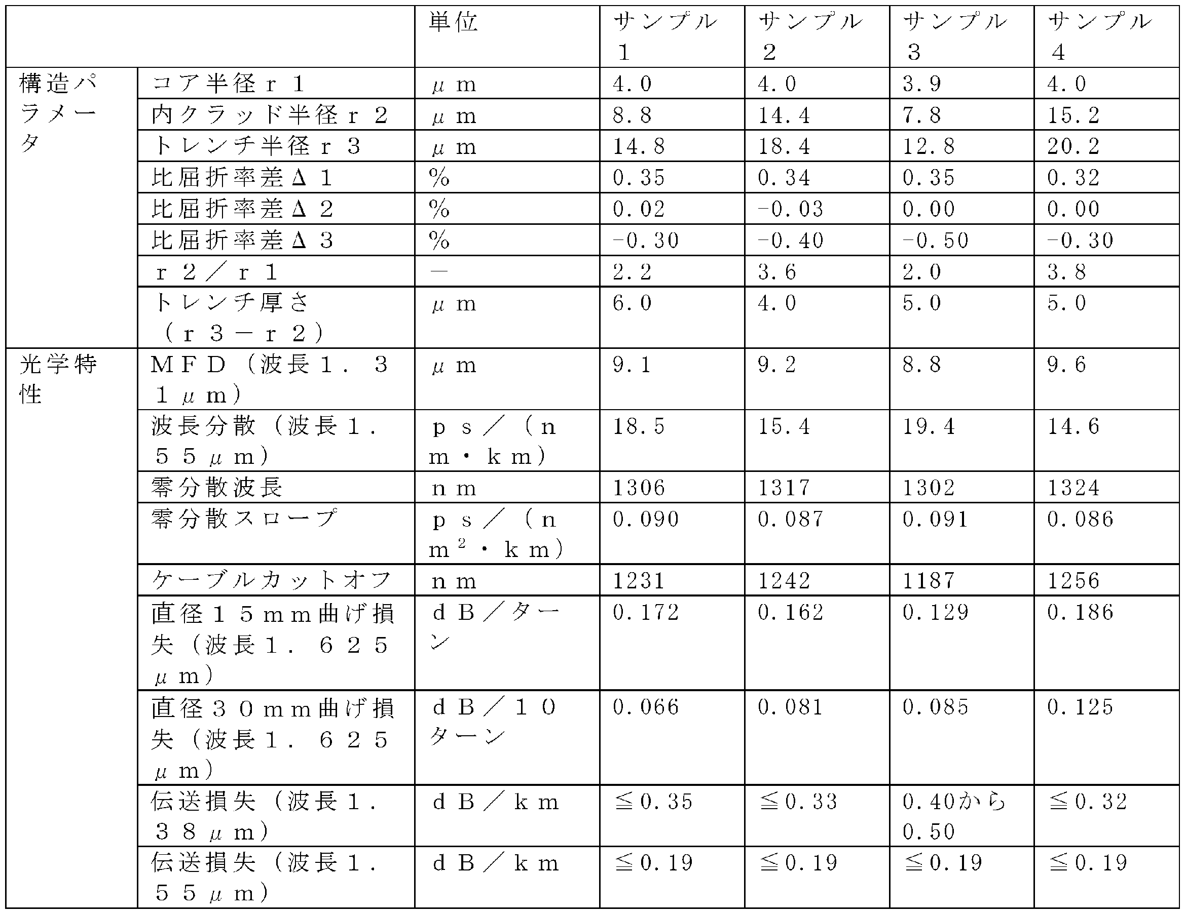
- Table 1 shows the specifications and characteristics of the optical fibers according to sample numbers 1 to 4 as examples and comparative examples. All radii of the outer cladding 123 are 62.5 ⁇ m.
- Samples 1 and 2 achieve good values for each optical characteristic.
- the transmission loss at the wavelength of 1.38 ⁇ m is excessive.
- Sample 4 has excessive bending loss with a diameter of 30 mm at a wavelength of 1.625 ⁇ m. Therefore, the value obtained by dividing the radius r2 of the inner clad 121 by the radius r1 of the core 11 (r2/r1) may be 2.2 or more and 3.6 or less.
- the thickness t2 of the secondary resin layer 15 is 5.0 ⁇ m or more and 17.5 ⁇ m or less.
- the vibration of the glass fiber 13 causes coating eccentricity of several ⁇ m, which may locally thin the secondary resin layer 15 .
- the coating eccentricity is the distance between the center of the glass fiber 13 and the center of the outer periphery of the coating resin layer 16A. If foreign matter adhering to the roller in the drawing process overlaps with such a locally thinned portion, it may cause breakage of the optical fiber 10A, thereby reducing the yield of the optical fiber 10A.
- the outer diameter D4 of the secondary resin layer 15 is 170 ⁇ m ⁇ 5 ⁇ m, that is, 165 ⁇ m or more and 175 ⁇ m or less.
- the Young's modulus of the secondary resin layer 15 at 23°C may be 1200 MPa or more and 2800 MPa or less, 1500 MPa or more and 2800 MPa or less, or 2000 MPa or more and 2700 MPa or less.
- the Young's modulus of the secondary resin layer 15 is 1200 MPa or more, the lateral pressure resistance characteristics can be easily improved, and when it is 2800 MPa or less, the secondary resin layer 15 can be given appropriate toughness, thereby improving tensile strength and low temperature characteristics. becomes easier.
- the Young's modulus of the secondary resin layer 15 is 2800 MPa or less, deterioration of the appearance and cracking of the secondary resin layer 15 due to external damage are less likely to occur.
- the secondary resin layer 15 having the above properties is a base resin containing an oligomer containing urethane (meth)acrylate, a monomer, and a photopolymerization initiator, or a resin composition containing the base resin and hydrophobic inorganic oxide particles. It can be formed by curing.
- (Meth)acrylate means acrylate or the corresponding methacrylate. The same applies to (meth)acrylic acid and the like.
- Inorganic oxide particles are spherical particles. The inorganic oxide particles are at least one selected from the group consisting of silicon dioxide (silica), zirconium dioxide (zirconia), aluminum oxide (alumina), magnesium oxide (magnesia), titanium oxide (titania), tin oxide and zinc oxide. be.
- the average primary particle size of the inorganic oxide particles may be 500 nm or less. From the viewpoint of increasing the Young's modulus of the secondary resin layer 15, the average primary particle size of the inorganic oxide particles may be 5 nm or more, or 10 nm or more.
- the surfaces of the inorganic oxide particles are hydrophobically treated.
- Hydrophobic treatment means that a hydrophobic group is introduced to the surface of the inorganic oxide particles.
- Hydrophobic groups are reactive groups such as (meth)acryloyl groups (ultraviolet curable functional groups), or aliphatic hydrocarbon groups (e.g., alkyl groups), aromatic hydrocarbon groups (e.g., phenyl groups). It may be a non-reactive group such as When the inorganic oxide particles have a reactive group, it becomes easier to form a resin layer with a high Young's modulus.
- a UV-curable functional group may be introduced onto the surface of the inorganic oxide particles.
- UV-curable functional groups can be introduced to the surfaces of the inorganic oxide particles.
- Silane compounds having UV-curable functional groups include, for example, 3-methacryloxypropyltrimethoxysilane.
- urethane (meth)acrylate an oligomer obtained by reacting a polyol compound, a polyisocyanate compound and a hydroxyl group-containing (meth)acrylate compound can be used.
- polyol compounds include polytetramethylene glycol and the like.
- polyisocyanate compounds include 2,4-tolylene diisocyanate and the like.
- hydroxyl group-containing (meth)acrylate compounds include 2-hydroxyethyl (meth)acrylate and the like.
- the base resin may further contain epoxy (meth)acrylate as an oligomer.
- epoxy (meth)acrylate an oligomer obtained by reacting an epoxy resin having two or more glycidyl groups with a compound having a (meth)acryloyl group can be used.
- the monomer at least one selected from the group consisting of monofunctional monomers having one polymerizable group and polyfunctional monomers having two or more polymerizable groups can be used. You may use a monomer in mixture of 2 or more types. Monofunctional monomers include, for example, methyl (meth)acrylate. Examples of polyfunctional monomers include ethylene glycol di(meth)acrylate. From the viewpoint of increasing the Young's modulus of the resin layer, the monomer may contain a polyfunctional monomer or a monomer having two polymerizable groups.
- the photopolymerization initiator can be appropriately selected and used from radical photopolymerization initiators.
- the thickness t1 of the primary resin layer 14 is 7.5 ⁇ m or more and 17.5 ⁇ m or less.
- the outer diameter D3 of the primary resin layer 14 is 140 ⁇ m or more and 160 ⁇ m or less.
- the outer diameter D3 of the primary resin layer 14 is 160 ⁇ m or less, that is, the thickness t1 of the primary resin layer 14 is 17.5 ⁇ m or less, the outer diameter of the optical fiber 10A is within a predetermined range (165 ⁇ m or more and 175 ⁇ m or less). , the thickness t2 (5.0 ⁇ m or more) of the secondary resin layer 15 can be sufficiently secured.
- the Young's modulus of the primary resin layer 14 may be 0.10 MPa or more and 0.30 MPa or less at 23°C.
- the Young's modulus of the primary resin layer 14 is 0.10 MPa or more, coating cracks called voids and peeling (delamination) of the coating are less likely to occur in the primary resin layer 14 at a screening tension of 1.5 kg or more.
- This optical fiber 10A has no problem of low temperature characteristics.
- the Young's modulus of the primary resin layer 14 is 0.30 MPa or less, particularly excellent lateral pressure resistance is obtained within the range of the thickness t1 of the primary resin layer 14 described above.
- the optical fiber 10A provided with the primary resin layer 14 having a Young's modulus of 0.10 MPa or more and 0.30 MPa or less may be referred to as a specialized lateral pressure resistant optical fiber.
- the Young's modulus of the primary resin layer 14 may be 0.30 MPa or more and 0.50 MPa or less at 23°C.
- the Young's modulus of the primary resin layer 14 is 0.30 MPa or more, coating cracks called voids and peeling (delamination) of the coating are less likely to occur in the primary resin layer 14 at a screening tension of 2.0 kg or more. Disconnection is less likely to occur when making cables, improving productivity.
- the Young's modulus of the primary resin layer 14 is 0.50 MPa or less, lateral pressure resistance is obtained within the range of the thickness t1 of the primary resin layer 14 described above.
- the optical fiber 10A including the primary resin layer 14 having a Young's modulus of 0.30 MPa or more and 0.50 MPa or less may be referred to as a high screening tension type optical fiber.
- the primary resin layer 14 having the above properties can be formed, for example, by curing a resin composition containing an oligomer containing urethane (meth)acrylate, a monomer, a photopolymerization initiator, and a silane coupling agent.
- the urethane (meth)acrylate, monomer, and photopolymerization initiator may be appropriately selected from the compounds exemplified for the base resin above.
- the resin composition forming the primary resin layer 14 has a composition different from that of the base resin forming the secondary resin layer 15 .
- a primary resin layer 14 was formed on the outer circumference of a glass fiber 13 having a diameter of 125 ⁇ m and composed of a core 11 and a clad 12, and a secondary resin layer 15 was further formed on the outer circumference to prepare a plurality of samples of the optical fiber 10A.
- Table 2 shows the outer diameter, thickness, and Young's modulus at 23° C. of the primary resin layer 14, the outer diameter, thickness, and Young's modulus at 23° C. of the secondary resin layer 15, lateral pressure resistance characteristics, and a table showing screening tension.
- the structure of the glass fibers 13 of sample numbers 5 and 6 was the same as that of sample number 1 in Table 1, and the structure of the glass fiber 13 of sample number 7 was the same as that of sample number 2 in Table 1.
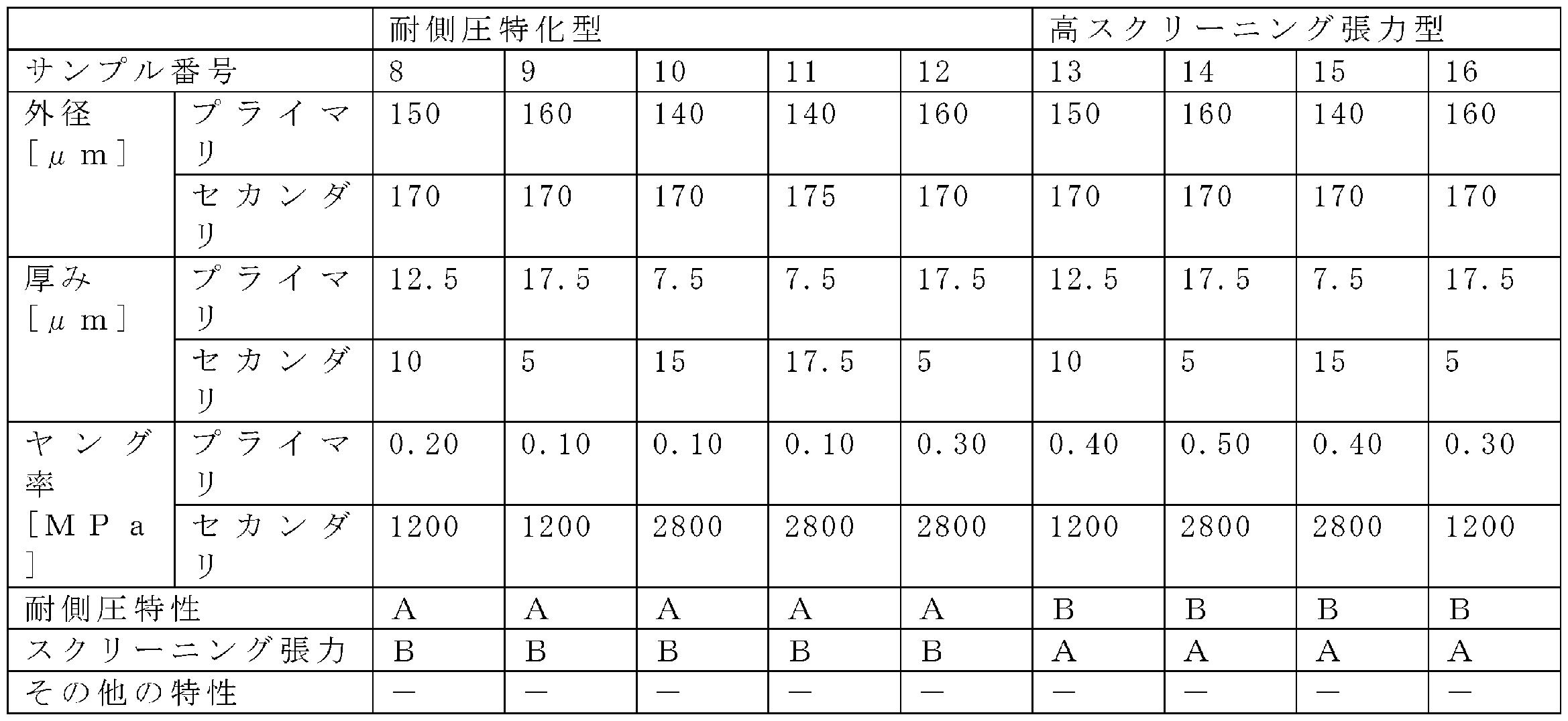
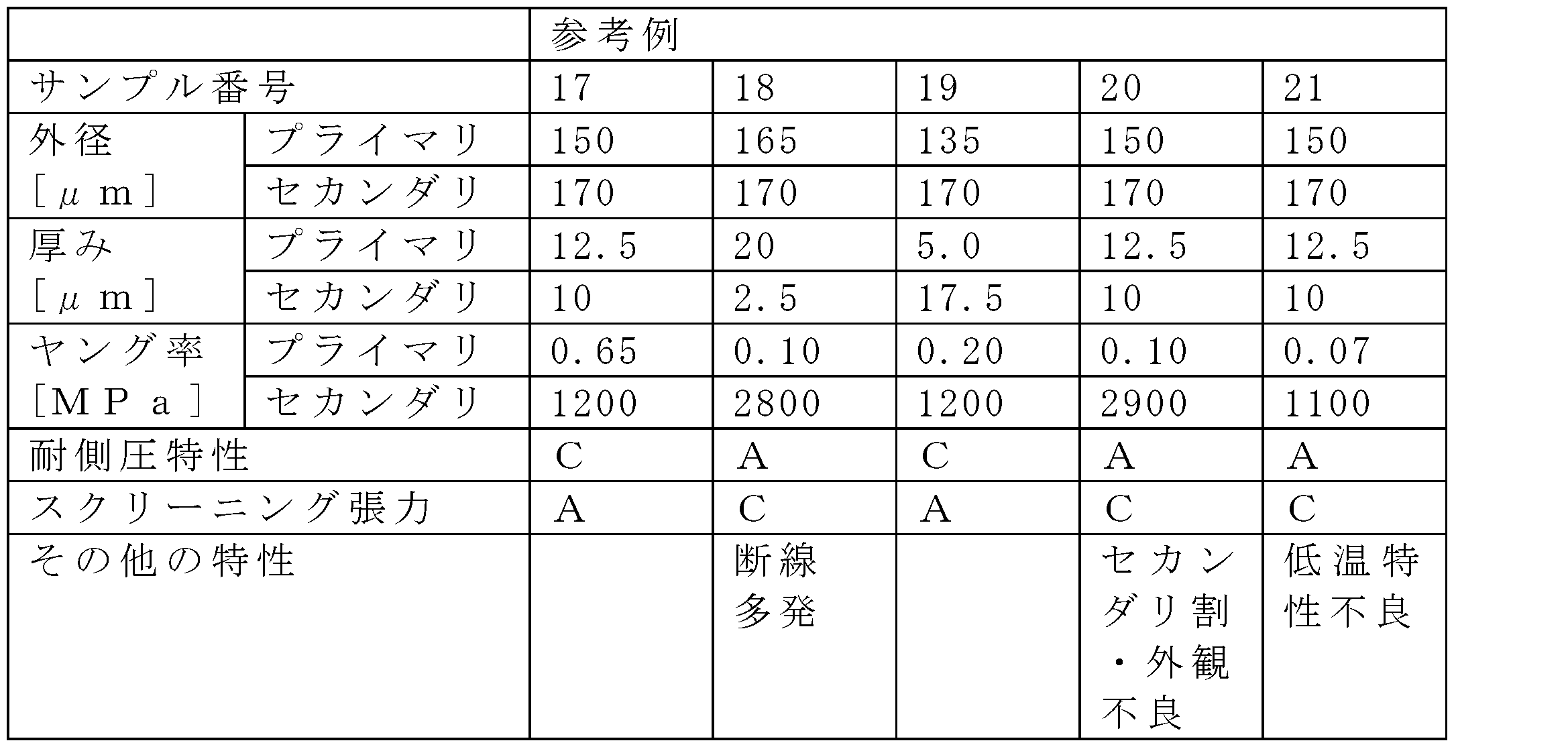
- the primary resin layer 14 is formed on the outer circumference of the glass fiber with a diameter of 125 ⁇ m having a clad composed of a single composition, and the secondary resin layer 15 is further formed on the outer circumference.
- a plurality of samples of the optical fiber were produced. Silica glass doped with fluorine was used for the clad.
- Tables 3 and 4 below show the outer diameter, thickness, and Young's modulus at 23°C of the primary resin layer 14, the outer diameter, thickness, and Young's modulus at 23°C of the secondary resin layer 15, and the resistance of each sample.
- Fig. 3 is a table showing lateral pressure characteristics, screening tension, and other characteristics;
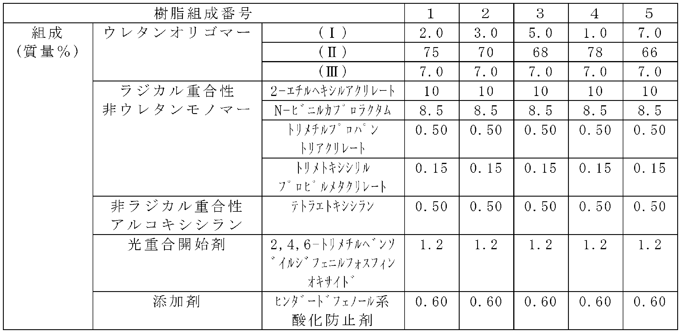
- a primary resin layer 14 with a Young's modulus of 0.10 MPa and a primary resin layer 14 with a Young's modulus of 0.20 MPa were obtained with the resin composition 1 shown in Table 5. These primary resin layers 14 are hereinafter referred to as resin P1.
- a primary resin layer 14 with a Young's modulus of 0.30 MPa and a primary resin layer 14 with a Young's modulus of 0.40 MPa were obtained with the resin composition 2 shown in Table 5.
- These primary resin layers 14 are hereinafter referred to as resin P2.
- a primary resin layer 14 having a Young's modulus of 0.50 MPa was obtained with resin composition 3 shown in Table 5.
- this primary resin layer 14 will be referred to as resin P3.
- a primary resin layer 14 having a Young's modulus of 0.07 MPa was obtained with resin composition 4 shown in Table 5.
- a primary resin layer 14 having a Young's modulus of 0.65 MPa was obtained with resin composition 5 shown in Table 3.
- Urethane oligomer (I) is specifically HEA-TDI-(PPG3000-TDI) 2,1 -HEA.
- Urethane oligomer (II) is specifically HEA-TDI-(PPG3000-TDI) 2,1 -EH.
- Urethane oligomer (III) is specifically HEA-TDI-(PPG3000-TDI) 2,1 -SiI.
- UA1 was prepared by reacting 2,4-tolylene diisocyanate and polypropylene glycol having a number average molecular weight of 2000 at a weight ratio of 1:5.7.
- UA2 was prepared by reacting 2,4-tolylene diisocyanate and polypropylene glycol having a number average molecular weight of 10,000 at a weight ratio of 1:28.
- resin S2 those having a Young's modulus of 2800 MPa and 2900 MPa are designated as resin S2.
- resin S2 had the composition shown in Table 7 below, and the difference in Young's modulus was obtained by adjusting the UV power or sorting according to the variation of each sample.
- UA is a urethane acrylate obtained by reacting polypropylene glycol with a molecular weight of 600, 2,4-tolylene diisocyanate, and hydroxyethyl acrylate.
- EA is epoxy diacrylate.
- the Young's modulus of the primary resin layer 14 was measured by the Pullout Modulus (POM) method at 23°C.
- Metal cylinders are adhered to two locations on the optical fiber 10A separated by a predetermined interval.
- the coating resin layer between the cylinders that is, the portions of the primary resin layer 14 and the secondary resin layer 15 are removed to expose the glass. Cut the optical fiber outside the metal cylinder, ie, the side away from the other metal cylinder.
- the length of the optical fiber is the sum of the length of the portion bonded to both metal cylinders and the length of the portion between the metal cylinders.
- One metal cylinder was then fixed, and the other metal cylinder was gently moved slightly in the opposite direction of the previously fixed metal cylinder.
- L is the length of the metal cylinder, that is, the length to which the optical fiber 10A is bonded
- Z is the movement amount of the chuck
- Dp is the outer diameter of the primary resin layer
- Df is the outer diameter of the glass fiber 13A
- Df is the primary resin layer.
- the Young's modulus of the secondary resin layer 15 is measured under an environment of 23 ⁇ 2° C. and 50 ⁇ 10% RH using a pipe-shaped coating resin layer having a length of 50 mm or longer, which is obtained by extracting the glass fiber 13 from the optical fiber 10A. A tensile test was performed with a gauge length of 25 mm, and the value was obtained from the 2.5% secant value.
- the lateral pressure resistance characteristics were evaluated by the following method.
- An optical fiber 10A with a length of 500 m is wound in one layer with a tension of 80 g on a bobbin with a body diameter of 405 mm, which is wound with a plain-woven metal mesh having a wire outer diameter of 50 ⁇ m and a pitch of 150 ⁇ m. loss was measured.
- the optical fiber 10A was wound around a bobbin with a barrel diameter of 280 mm and then removed from the bobbin so that it was wound into a ring with a diameter of about 280 mm. In that state, the transmission loss of the optical fiber 10A was measured. Each of these measurements was performed three times, and their average value was obtained. The difference between both average values was taken as the transmission loss difference.
- the transmission loss is the transmission loss of light with a wavelength of 1550 nm, and was calculated from the loss spectrum measured by the cutback method.
- a case where the transmission loss difference was 1.0 dB/km or less was evaluated as "A" withstanding lateral pressure characteristics.
- a case in which the transmission loss difference was more than 1.0 dB/km and not more than 1.5 dB/km was evaluated as side pressure resistance characteristic "B".
- the case where the transmission loss difference exceeded 1.5 dB/km was evaluated as the lateral pressure resistance characteristic "C".
- the screening tension was evaluated by the following method. 1000 km of optical fiber was rewound under tension. Screening tension "A" is evaluated when the number of disconnections is 5 times or less when rewinding an optical fiber with a length of 1000 km with a tension of 2.0 kg, more specifically 1.9 kg or more and 2.3 kg or less. bottom. In the tension test at a tension of 2.0 kg, the optical fiber with a length of 1000 km was broken more than 5 times when rewound, but at a tension of 1.5 kg, more specifically 1.4 kg or more and 1.6 kg or less, the length was broken. A screening tension of "B" was evaluated when the number of disconnections was 5 or less when rewinding an optical fiber of 1000 km.
- the thickness of the primary resin layer 14 is 7.5 ⁇ m or more and 17.5 ⁇ m or less
- the thickness of the secondary resin layer 15 is 5.0 ⁇ m or more and 17.5 ⁇ m or less.
- Table 2 that is, when the optical fiber includes the glass fiber 13 of the present embodiment, both the side pressure resistance and the screening tension are evaluated as A. characteristics
- Table 3 when the Young's modulus of the primary resin layer is 0.10 MPa or more and 0.30 MPa or less, it is possible to provide an optical fiber specialized in lateral pressure resistance with an evaluation of A for lateral pressure resistance.
- the Young's modulus of the primary resin layer is 0.30 MPa or more and 0.50 MPa or less, it is possible to provide a high screening tension type optical fiber with a screening tension evaluation of A, that is, a low-temperature characteristic specialized optical fiber. The higher the screening tension, the less likely the optical fibers are to be broken in the tape forming process, which is a post-process, and the higher the yield of the multicore cable.
- the frequency of disconnection of the optical fiber tends to be higher than that of a conventional optical fiber having an outer diameter of, for example, 250 ⁇ m. be. If disconnection of the optical fiber 10A occurs in the manufacturing process, the manufacturing efficiency of the optical fiber 10A may decrease. In response to such a problem, the inventor found that the frequency of disconnection of the optical fiber 10A in the manufacturing process depends on the amount of eccentricity of the glass fiber 13 in the optical fiber 10A.
- the glass fiber 13 When passing through the die in the resin coating device, the glass fiber 13 vibrates in the radial direction of the glass fiber 13, the glass fiber 13 is eccentric with respect to the opening of the die, and the coating resin layer 16A is formed in this state. end up Therefore, the thickness of the coating resin layer 16A is reduced in the direction in which the central axis of the glass fiber 13 deviates from the central axis of the optical fiber 10A.
- a large stress may be applied locally to the glass fiber 13 through the thin portion of the coating resin layer 16A. be. For this reason, damage such as cracks may occur in the glass fiber 13 .
- the damage to the glass fiber 13 may cause the optical fiber 10A to break.
- An optical fiber having a small outer diameter may be broken even when eccentricity occurs to a degree that does not lead to breakage in conventional optical fibers.
- the present inventor performed a Fourier transform on a waveform indicating the amount of eccentricity of the glass fiber 13 with respect to the position in the axial direction of the glass fiber 13, and analyzed the spectrum obtained by the Fourier transform. bottom.
- the present inventors have found that the breakage of the optical fiber 10A is suppressed by adjusting the manufacturing conditions and the manufacturing apparatus so that the maximum amplitude in the spectrum obtained by Fourier transforming the eccentricity amount waveform of the glass fiber 13 is suppressed to a predetermined value or less.
- the present embodiment is based on the above knowledge discovered by the inventor.
- FIG. 4 is a schematic diagram for explaining the definition of the amount of eccentricity of the glass fiber 13.
- FIG. 5 is a diagram of an eccentricity amount waveform showing the amount of eccentricity of the glass fiber 13 with respect to the position of the glass fiber 13 in the axial direction.
- FIG. 6 is a diagram showing an example of a spectrum obtained by Fourier transforming an eccentricity amount waveform.
- FIG. 4 is only an explanatory diagram and does not show the state of the optical fiber 10A of this embodiment. However, in order to simplify the explanation, the same reference numerals as in FIG. 1 are used.
- the amount of eccentricity d of the glass fiber 13 is the distance from the central axis RC with respect to the outer periphery of the coating resin layer 16A to the central axis GC of the glass fiber 13, that is, the amount of deviation in the radial direction. is defined as the displacement of
- the eccentricity of the glass fiber 13 is measured by, for example, an eccentricity variation observation device.
- the eccentricity fluctuation observation device is configured as an eccentric image recognition device.
- the eccentricity variation observation device has, for example, a first light source, a first imaging section, a second light source, and a second imaging section.
- the first light source is arranged to emit light in the radial direction of the optical fiber 10A to be measured.
- the light from the first light source includes wavelengths that pass through the coating resin layer 16A.
- the first imaging unit is arranged to face the first light source with the optical fiber 10A to be measured interposed therebetween, and is configured to acquire an image of light transmitted through the optical fiber 10A.
- the second light source and the second imaging section are configured in the same manner as the first light source and the first imaging section, except that they are arranged so as to be perpendicular to the opposing direction of the first light source and the first imaging section.
- the position of the outer periphery of the coating resin layer 16A and the position of the coating resin layer By obtaining the position of the inner periphery of 16A, that is, the position of the outer periphery of the glass fiber 13, the eccentricity of the glass fiber 13, which is the distance between the centers thereof, can be measured. That is, the eccentricity of the glass fiber 13 can be measured while the optical fiber 10A is not destroyed.
- the amount of eccentricity of the glass fiber 13 is measured at a plurality of measurement points set at predetermined intervals in the axial direction of the glass fiber 13 .
- the waveform (distribution) of the eccentricity can be obtained by plotting the measurement results with the positions of the plurality of measurement points on the horizontal axis and the eccentricity at each position on the vertical axis.
- the waveform of the amount of eccentricity of the glass fiber 13 is also referred to as "the waveform of the amount of eccentricity”.
- the eccentricity amount waveform shown in FIG. 5 is obtained.
- “Amount of eccentricity” on the vertical axis of FIG. 5 is the absolute value of the amount of eccentricity regardless of the direction.
- the eccentricity waveform in the actual optical fiber 10A has a complicated shape. Therefore, the present inventor performed a Fourier transform on the eccentricity amount waveform of the optical fiber 10A and analyzed the spectrum obtained by the Fourier transform, as shown in FIG.
- the inventor succeeded in reducing the disconnection frequency by suppressing the "maximum value of the amplitude of the eccentricity" in the spectrum obtained by Fourier transforming the eccentricity waveform.
- a component that maximizes the amplitude of the eccentricity is also called a “maximum amplitude component”.
- the optical fiber 10A of this embodiment satisfies at least one of the following requirements regarding the amount of eccentricity of the glass fiber 13.
- the maximum amplitude of the eccentricity (amplitude value of the maximum amplitude component) is 6 ⁇ m or less. If the maximum value of the amplitude of the eccentricity exceeds 6 ⁇ m, the glass fiber 13 is locally largely eccentric at the position where the peaks of the eccentricity of the frequency components of the eccentricity having different periods overlap each other. For this reason, the coating resin layer 16A tends to become thin locally. As a result, the disconnection frequency of the glass fiber 13 may increase. In contrast, in the present embodiment, the maximum value of the amplitude of the eccentricity is set to 6 ⁇ m or less.
- the maximum value of the amplitude of the eccentricity is not particularly limited, and is preferably as close to 0 ⁇ m as possible.
- the wavelength at which the amplitude of the eccentricity is maximized is 0.1 m or more. If the wavelength at which the amplitude of the eccentricity is maximum is less than 0.1 m, the component with the maximum amplitude of the eccentricity and other components having different wavelengths often overlap. Therefore, the coating resin layer 16A is often locally thin. That is, the number of locations where the thickness of the coating resin layer 16A is thin increases per unit length of the glass fiber 13 in the axial direction. As a result, the disconnection frequency of the glass fiber 13 may increase.
- the wavelength at which the amplitude of the eccentricity is maximum is set to 0.1 m or more, "another component having a different wavelength" that overlaps the component with the maximum amplitude of the eccentricity is reduced. can do.
- This can prevent the coating resin layer 16A from being locally thinned. That is, it is possible to suppress an increase in the number of locations where the thickness of the coating resin layer 16A is thin per unit length of the glass fiber 13 in the axial direction. As a result, the disconnection frequency of the glass fiber 13 can be reduced.
- the upper limit of the wavelength at which the amplitude of the eccentricity is maximized is not particularly limited, and is preferably as large as possible. However, considering the linear velocity in the optical fiber manufacturing apparatus 50, which will be described later, the wavelength at which the amplitude of the eccentricity is maximized is, for example, 1 m or less.
- FIG. 7 is a schematic configuration diagram showing an optical fiber manufacturing apparatus 50 according to this embodiment.
- An optical fiber manufacturing apparatus 50 according to this embodiment will be described with reference to FIG.
- the optical fiber manufacturing apparatus 50 includes, for example, a drawing furnace 510, a fiber position measuring unit 522, a cooling device 523, an outer diameter measuring unit 524, a resin coating device 530, a curing device 540, a conveying unit 550, A bobbin 560 and a control section 590 are provided. Device members other than the control unit 590 are provided in this order.
- the drawing furnace 510 has a gripping mechanism 512 , a furnace core tube 514 , a heating element 516 and a gas supply section 518 .
- the side closer to the gripping mechanism 512 is called “upstream”
- the side closer to the bobbin 560 is called "downstream”.
- the drawing furnace 510 is configured to form the glass fiber 13 .
- a glass fiber 13 having a small diameter is formed by heating the glass preform G in a drawing furnace 510 and drawing the softened glass.
- the fiber position measuring section 522 is configured to measure the horizontal position of the glass fiber 13 .
- Cooling device 523 is configured to cool glass fiber 13 formed in drawing furnace 510 .
- the outer diameter measuring section 524 is configured to measure the outer diameter of the glass fiber 13 before resin coating.
- the resin coating device 530 is configured to form the coating resin layer 16A so as to cover the outer periphery of the glass fiber 13.
- the resin coating device 530 has a die for applying an ultraviolet curable resin composition to the outer periphery of the glass fiber 13 while inserting the glass fiber 13 .
- the resin coating device 530 has two dies for forming the primary resin layer 14 and the secondary resin layer 15 in this order from the central axis side of the glass fiber 13 toward the outer peripheral side.
- the curing device 540 is configured to irradiate the coating resin layer 16A with ultraviolet rays to cure the coating resin layer 16A.
- the transport unit 550 is configured to transport the optical fiber 10A with the coating resin layer 16A cured.
- the transport section 550 has, for example, a plurality of guide rollers 552 and 556 and a capstan 554 .
- the direct roller 552a which is one of the plurality of guide rollers 552, is positioned directly below the curing device 540, for example.
- the capstan 554 is provided, for example, downstream of the roller 552a directly below, and is configured to convey (pull) the optical fiber 10A with a predetermined tension while gripping the optical fiber 10A between the belt and the roller.
- a guide roller 552 b among the plurality of guide rollers 552 is provided between the direct-lower roller 552 a and the capstan 554 .
- screening rollers 552c, 552d, and 552e are provided downstream of the capstan 554 and configured to apply screening tension to the optical fiber 10A together with the capstan 554.
- the guide roller 556 is provided on the downstream side of the screening roller 552e, and is configured to adjust the tension of the optical fiber 10A by moving up and down according to changes in the tension of the optical fiber 10A.
- the bobbin 560 is provided downstream of the guide roller 556, for example, and configured to wind the optical fiber 10A.
- the controller 590 is, for example, connected to each part of the optical fiber manufacturing apparatus 50 and configured to control them.
- the control unit 590 is configured as, for example, a computer.
- the optical fiber manufacturing apparatus 50 in order to manufacture the optical fiber 10A that satisfies the above-described requirements for the amount of eccentricity of the glass fiber 13, is configured, for example, as follows.
- the longest roller has a circumferential length of, for example, 0.2 m or more.
- the circumference of the largest guide roller 552 is, for example, 0.9 m or less.
- the conveying section 550 has, for example, a vibration suppressing section 555.
- the vibration suppressing part 555 is installed, for example, downstream of the hardening device 540 and upstream of the direct-lower roller 552 a positioned directly below the hardening device 540 .
- the vibration suppression unit 555 is configured such that, for example, two rollers contact the optical fiber 10A from different directions to suppress vibration of the optical fiber 10A.
- the directly below roller 552a positioned directly below the curing device 540 is fixed independently of other device members involved in the manufacture of the optical fiber 10A, for example.
- the direct-lower roller 552a is, for example, fixed to the floor without being connected to other device members.
- the maximum value of the amplitude of the amount of eccentricity can be reduced, and the wavelength at which the amplitude of the amount of eccentricity becomes maximum can be lengthened.
- Vibration of the optical fiber 10A is suppressed by a vibration suppressor 555 installed downstream of the curing device 540 and upstream of the direct-lower roller 552a located directly below the curing device 540;
- the direct-lower roller 552a positioned directly under the curing device 540 is used in a state of being fixed independently of other device members involved in the manufacture of the optical fiber 10A.
- the first eccentricity of the glass fiber 13 from the central axis with reference to the outer circumference of the primary resin layer 14 is measured.
- the average value of the first eccentricity is smaller than the average value of the second eccentricity may In this case, the amount of eccentricity of the primary resin layer 14, which has a cushioning effect, is reduced, and the lateral pressure resistance is improved.
- a plurality of measurement points is, for example, five or more points.
- optical fibers with sample numbers 22 to 25 were produced under the conditions shown in Table 8 below. Common conditions not listed in Table 8 are as follows. Outer diameter of glass fiber 13: 125 ⁇ m Number of layers of coating resin layer 16A: 2 layers
- connection frequency measurement The optical fiber 10A of each sample was rewound with a tension of 1.5 kg, and the number of disconnections of the optical fiber 10A was measured.
- the disconnection frequency was determined as the number of disconnections per 1000 kilometers (1 Mm). As a result, when the disconnection frequency was less than 5 times/Mm, it was evaluated as "good", and when the disconnection frequency was 5 times/Mm or more, it was evaluated as "bad". The evaluation results for each sample are described with reference to Table 8 below.
- the maximum amplitude of the eccentricity was 6 ⁇ m or less in the spectrum obtained by Fourier transforming the waveform of the eccentricity.
- the wavelength at which the amplitude of the amount of eccentricity becomes maximum was 0.1 m or more.
- the optical fiber 10A was difficult to break, and the frequency of breakage was less than 5 times/Mm.
- the optical fiber 10A could be stably conveyed by the maximum guide roller by setting the peripheral length of the maximum guide roller to 0.2 m or more.
- the provision of the vibration suppressing portion 555 stabilizes the position of the central axis of the glass fiber 13 when coating the coating resin layer 16A due to the vibration from the conveying portion 550. could be maintained.
- the direct roller 552a since the direct roller 552a was fixed independently from other device members, it was possible to suppress an increase in vibration of the direct roller 552a and a shortening of the period.
- sample numbers 22 to 25 the maximum value of the amplitude of the eccentricity can be reduced in the spectrum obtained by Fourier transforming the waveform of the eccentricity, and the wavelength at which the amplitude of the eccentricity is maximized can be lengthened. . As a result, it was confirmed that sample numbers 22 to 25 were able to reduce the frequency of disconnection in spite of their small diameter.
- FIG. 8 is a diagram showing a cross section perpendicular to the axial direction of the optical fiber 10B according to the third embodiment.
- the optical fiber 10B is a so-called optical fiber core wire, and includes a glass fiber 13 including a core 11 and a clad 12, and a primary resin layer 14, a secondary resin layer 15 and a colored layer 17 (second 1 colored layer) and a coating resin layer 16B.
- the structure and characteristics of the glass fiber 13 and the secondary resin layer 15 are the same as those of the first embodiment described above.
- the colored layer 17 is in contact with the outer peripheral surface of the secondary resin layer 15 and covers the entire secondary resin layer 15 .
- the colored layer 17 constitutes the outermost layer of the coating resin layer 16B.
- the colored layer 17 is made of, for example, an ultraviolet curable resin containing a pigment.
- a thickness t3 of the colored layer 17 is 3.0 ⁇ m or more and 10.0 ⁇ m or less.
- the outer diameter D5 of the colored layer 17, that is, the outer diameter of the coating resin layer 16B is 180 ⁇ m ⁇ 5 ⁇ m, that is, 175 ⁇ m or more and 185 ⁇ m or less.
- the colored layer 17 is made of a cured resin composition containing colored ink. When the coating resin layer 16B has the colored layer 17 as in this embodiment, the colored layer 17 facilitates identification of the optical fiber 10B.
- the thickness t3 of the colored layer 17 By setting the thickness t3 of the colored layer 17 to 3.0 ⁇ m or more, the color of the core wire in appearance is sufficiently dark, and the distinguishability is improved. Furthermore, color unevenness due to vibration of the optical fiber 10B in the manufacturing process can be suppressed.
- the colored layer 17 contains a pigment, if the colored layer 17 has an excessive thickness, the ultraviolet rays for curing the colored layer 17 do not sufficiently reach the deep part of the colored layer 17, and the colored layer 17 cannot be cured. may be insufficient. If the curing of the colored layer 17 is insufficient, the adhesive strength between the colored layer 17 and the secondary resin layer 15 decreases, and when the tape material is peeled off, the colored layer 17 separates from the secondary resin layer 15 without separating from the tape material.
- the Young's modulus of the primary resin layer 14 slightly increases due to the ultraviolet irradiation for curing the colored layer 17 compared to the first embodiment. It is believed that this is because the primary resin layer 14 is further cured by irradiation with ultraviolet rays for curing the colored layer 17 .
- the Young's modulus of the primary resin layer 14 may be 0.10 MPa or more and 0.40 MPa or less at 23°C.
- the Young's modulus of the primary resin layer 14 is 0.10 MPa or more, coating cracks called voids and peeling (delamination) of the coating are less likely to occur in the primary resin layer 14 at a screening tension of 1.5 kg or more.
- This optical fiber 10B does not have the problem of low temperature characteristics.
- the Young's modulus of the primary resin layer 14 is 0.40 MPa or less, particularly excellent lateral pressure resistance is obtained within the range of the thickness t1 of the primary resin layer 14 described in the first embodiment.
- the optical fiber 10B provided with the primary resin layer 14 having a Young's modulus of 0.10 MPa or more and 0.40 MPa or less may be referred to as a specialized lateral pressure resistant optical fiber.
- This optical fiber has a colored layer on top of the two coating layers.
- the Young's modulus of the primary resin layer 14 may be 0.40 MPa or more and 0.60 MPa or less at 23°C.
- the Young's modulus of the primary resin layer 14 is 0.40 MPa or more, coating cracks called voids and peeling (delamination) of the coating are less likely to occur in the primary resin layer 14 at a screening tension of 2.0 kg or more. Disconnection is less likely to occur when making cables, improving productivity.
- the Young's modulus of the primary resin layer 14 is 0.60 MPa or less, sufficient lateral pressure resistance is obtained within the range of the thickness t1 of the primary resin layer 14 described in the first embodiment.
- the optical fiber 10B including the primary resin layer 14 having a Young's modulus of 0.40 MPa or more and 0.60 MPa or less may be referred to as a high screening tension type optical fiber.
- This optical fiber has a colored layer on top of the two coating layers.
- the structure and properties of the primary resin layer 14 are the same as those of the first embodiment described above, except for the Young's modulus.
- a primary resin layer 14 is formed on the outer circumference of a glass fiber 13 having a diameter of 125 ⁇ m, which is composed of a core 11 and a clad 12, a secondary resin layer 15 is formed on the outer circumference, and a colored layer 17 is formed on the outer circumference,
- Table 9 shows the outer diameter, thickness, and Young's modulus at 23°C of the primary resin layer 14, the outer diameter, thickness, and Young's modulus at 23°C of the secondary resin layer 15, and the color layer 17 for each sample prepared. It is a table showing outer diameter, lateral pressure resistance, screening tension, and other properties.
- the structure of the glass fiber 13 of sample numbers 26 and 27 was the same as that of sample number 1 in Table 1, and the structure of the glass fiber 13 of sample number 29 was the same as that of sample number 2 in Table 1.
- the compositions of the primary resin layer 14 and the secondary resin layer 15 of sample number 26 are the same as those of the resin P3 and the resin S2 of the first embodiment, respectively.
- the compositions of the primary resin layer 14 and the secondary resin layer 15 of sample number 27 are the same as those of the resin P2 and the resin S2 of the first embodiment, respectively.
- the compositions of the primary resin layer 14 and the secondary resin layer 15 of sample number 28 are the same as those of the resin P2 and the resin S1 of the first embodiment, respectively.
- the primary resin layer 14 is formed on the outer circumference of the glass fiber with a diameter of 125 ⁇ m having a clad composed of a single composition, and the secondary resin layer 15 is further formed on the outer circumference. Furthermore, a colored layer 17 was formed on the outer periphery, and a plurality of optical fiber samples were produced. Silica glass doped with fluorine was used for the clad. Tables 10 and 11 below show the outer diameter, thickness, and Young's modulus at 23° C. of the primary resin layer 14, the outer diameter, thickness, and Young's modulus at 23° C. of the secondary resin layer 15, and coloration for each sample produced. 4 is a table showing the outer diameter, lateral pressure resistance, screening tension, and other properties of layer 17;
- the specific compositions of the primary resin layer 14 and the secondary resin layer 15 are the same as in the example of the first embodiment.
- the Young's modulus of the primary resin layer 14 becomes slightly larger (from 0 MPa to 0.1 MPa) than in the example of the first embodiment due to the irradiation of ultraviolet rays when curing the colored layer 17 .
- the method of measuring the Young's modulus of the primary resin layer 14 and the secondary resin layer 15, the method of measuring the lateral pressure resistance characteristics and evaluation criteria, and the method of measuring and evaluation criteria of the screening tension are the same as in the example of the first embodiment.
- the thickness of the primary resin layer 14 is 7.5 ⁇ m or more and 17.5 ⁇ m or less
- the thickness of the secondary resin layer 15 is 5.0 ⁇ m or more and 17.5 ⁇ m or less
- the Young's thickness of the primary resin layer is
- the modulus is 0.10 MPa or more and 0.60 MPa or less
- the Young's modulus of the secondary resin layer at 23 ° C. is 1200 MPa or more and 2800 MPa or less
- the evaluation of lateral pressure resistance characteristics is A or B
- the evaluation of screening tension is A or B.
- the Young's modulus of the primary resin layer is 0.40 MPa or more and 0.60 MPa or less, it is possible to provide a high screening tension type optical fiber with a screening tension evaluation of A, that is, a low-temperature characteristic specialized optical fiber.
- A a screening tension evaluation of A
- the higher the screening tension the less likely the optical fibers are to be broken in the tape forming process, which is a post-process, and the higher the yield of the multicore cable.
- FIG. 9 is a diagram showing a cross section perpendicular to the axial direction of an optical fiber 10C as a modification of the third embodiment.
- the optical fiber 10C includes a coating resin layer 16C instead of the coating resin layer 16B of the third embodiment.
- the resin coating layer 16C further has a colored layer 18 (second colored layer) in addition to the configuration of the resin coating layer 16B of the third embodiment.
- the colored layer 18 is formed between the secondary resin layer 15 and the colored layer 17 and is a resin layer different in color from the colored layer 17 .
- the colored layer 18 includes a plurality of ring patterns spaced apart from each other in the axial direction of the glass fiber 13 .
- the colored layer 18 is formed, for example, by an inkjet method that ejects solvent-diluted ink.
- Solvent-diluted ink has the property of being removed by wiping with alcohol or the like. cover the
- the colored layer 18 is a layer whose thickness is discontinuous in the longitudinal direction of the optical fiber. When the optical fiber 10C is viewed along the length direction, there are also locations where the colored layer 18 is absent.
- the number of identifiable colors of the optical fiber core wire can be increased by the number of combinations of the number of colors of the colored layers 17 and the number of colors of the colored layers 18 . Therefore, the number of identifiable colors of the optical fiber can be remarkably increased.
- Reference Signs List 10A, 10B, 10C Optical fiber 11 Core 12 Clad 13 Glass fiber 14 Primary resin layer 15 Secondary resin layer 16A, 16B, 16C Coating resin layer 17 Colored layer (first colored layer) 18... Colored layer (second colored layer) DESCRIPTION OF SYMBOLS 50... Optical fiber manufacturing apparatus 121... Inner clad 122... Trench 123... Outer clad 510... Drawing furnace 512... Gripping mechanism 514... Furnace core tube 516... Heating element 518... Gas supply part 522... Fiber position measuring part 523...
- Cooling device 524 Outer diameter measuring unit 530 Resin coating device 540 Curing device 550 Conveying unit 552 Guide roller 552a Underlying roller 552b Guide rollers 552c, 552d, 552e Screening roller 554 Capstan 555 Vibration suppressing unit 556 Guide Roller 560 bobbin 590 control unit G glass base material GC, RC center shaft
Landscapes
- Physics & Mathematics (AREA)
- General Physics & Mathematics (AREA)
- Optics & Photonics (AREA)
- Chemical & Material Sciences (AREA)
- Dispersion Chemistry (AREA)
- Optical Fibers, Optical Fiber Cores, And Optical Fiber Bundles (AREA)
Abstract
Description
i)Δ1>Δ2>Δ4>Δ3
ii)0.005%≦Δ2-Δ4≦0.05%
iii)15μm-r2≦25μm
iv)30Δ%・μm2|V3|≦80Δ%・μm2
v)波長1310nmにおけるモードフィールド径が9.0μm以上9.5μm以下である。
vi)波長1550nmにおいて、曲げ直径15mmでの曲げ損失が0.5dB/ターン以下であり、曲げ直径20mmでの曲げ損失が0.2dB/ターン以下であり、曲げ直径30mmでの曲げ損失が0.005dB/ターン以下である。
光ファイバの接続損失を低減するためには、互いに接続される2本の光ファイバのモードフィールド径(MFD)の差を小さくすることが有効である。一般的に敷設されている光ケーブルに使用されている光ファイバ(いわゆる汎用ファイバ)の中心MFD(λ=1.31μm)が9.2μmであるのに対して、従来の耐曲げファイバの中心MFD(λ=1.31μm)は、8.6μmと、平均的に0.6μmのMFD差がある。このため、光ファイバの接続損失を低減するためには、耐曲げファイバのMFDを大きくすることが有効である。しかし、一般的に、ガラスファイバの外径(125μm±0.5μm)を維持したままMFDを大きくすると、曲げ損失が増大する。光ファイバの伝送損失を低く抑えるためには、曲げ損失の増大を防ぐことも重要である。
本開示によれば、曲げ損失の増大を抑えつつMFDを大きくすることが可能な光ファイバを提供することができる。
最初に、本開示の実施形態の内容を列記して説明する。本開示の一態様に係る光ファイバは、コア及びクラッドを含むガラスファイバを備える。クラッドは、コアの外周を覆う内クラッドと、内クラッドの外周を覆うトレンチと、トレンチの外周を覆う外クラッドと、を含む。内クラッドの屈折率は、コアの屈折率よりも低い。トレンチの屈折率は、内クラッドの屈折率よりも低い。外クラッドの屈折率は、トレンチの屈折率よりも高く、コアの屈折率よりも低い。コアにはゲルマニウムが添加されている。内クラッドの平均塩素質量濃度は500ppm以上5000ppm以下である。外クラッドの屈折率に対するコアの比屈折率差をΔ1、外クラッドの屈折率に対する内クラッドの比屈折率差をΔ2、外クラッドの屈折率に対するトレンチの比屈折率差をΔ3、コアの外周の半径をr1、内クラッドの外周の半径をr2、トレンチの外周の半径をr3としたとき、r2/r1は2.2以上3.6以下であり、r3-r2は3μm以上10μm以下であり、Δ1-Δ2は0.15%以上0.40%以下であり、|Δ2|は0.10%以下であり、Δ3は-0.70%以上-0.10%以下である。波長1310nmの光に対する光ファイバのモードフィールド径は、8.8μm以上9.6μm以下である。直径15mmのマンドレルに巻回されたときの波長1625nmの光に対するこの光ファイバの曲げ損失は、1ターンあたり1.0dB以下である。直径30mmのマンドレルに巻回されたときの波長1625nmの光に対する光ファイバの曲げ損失は、10ターンあたり0.1dB以下である。光ファイバの零分散波長は1300nm以上1324nm以下である。光ファイバのケーブルカットオフ波長は1260nm以下である。
本実施形態に係る光ファイバの具体例を、必要により図面を参照しつつ説明する。本発明はこれらの例示に限定されず、特許請求の範囲によって示され、特許請求の範囲と均等の意味及び範囲内でのすべての変更が含まれることが意図される。以下の説明では、図面の説明において同一の要素には同一の符号を付し、重複する説明を省略する。以下の説明において、或る要素の「外径」とは、光ファイバの軸方向の複数の位置における、当該要素の外径の平均値をいう。同様に、或る要素の「厚さ」とは、光ファイバの軸方向の複数の位置における、当該要素の厚さの平均値をいう。
図1は、第1実施形態に係る光ファイバ10Aの軸方向に垂直な断面を示す図である。光ファイバ10Aは、いわゆる光ファイバ素線であって、ITU-T G.652規格及びITU-T G.657規格のうち少なくとも一方に準拠する。ITU-T G.652規格に準拠するとは、G.652.A、G.652.B、G.652.C、及びG.652.Dのうち少なくとも一つに準拠することを意味する。ITU-T G.657規格に準拠するとは、G.657.A及びG.657.Bのうち少なくとも一つに準拠することを意味する。光ファイバ10Aは、コア11及びクラッド12を含むガラスファイバ13と、ガラスファイバ13の外周に設けられたプライマリ樹脂層14及びセカンダリ樹脂層15を含む被覆樹脂層16Aとを備えている。


ヤング率(MPa)=((1+n)W/πLZ)×ln(Dp/Df)
この時、ガラスファイバ13、セカンダリ樹脂層15、及び接着部は変形せず(伸びず)、プライマリ樹脂層14が変形して金属製シリンダが移動したとみなしている。
上記第1実施形態のように外径D4が小さい光ファイバ10Aを製造する工程においては、従来の外径、例えば250μmを有する光ファイバと比較して、光ファイバが断線する頻度が高くなりがちである。製造する工程において光ファイバ10Aの断線が生じると、光ファイバ10Aの製造効率が低下してしまうおそれがある。このような課題に対し、発明者は、製造する工程における光ファイバ10Aの断線頻度が、光ファイバ10Aにおけるガラスファイバ13の偏心量に依存することを見出した。
(x)硬化装置540の直下に位置する直下ローラ552aと、直下ローラ552aよりも下流における複数のガイドローラ552と、を含む全てのローラのうち、最も大きいローラの周長を、0.2m以上とする。
(y)硬化装置540よりも下流で、且つ、硬化装置540の直下に位置する直下ローラ552aよりも上流に設置された振動抑制部555により、光ファイバ10Aの振動を抑制する。
(z)硬化装置540の直下に位置した直下ローラ552aを、光ファイバ10Aの製造に係る他の装置部材から独立して固定した状態で使用する。
(x)、(y)および(z)のうち少なくともいずれかを実施すれば、上述の効果を少なからず得ることができる。ただし、上記(x)、(y)および(z)の多くを実施したほうが、上述の効果を安定的に得ることができる。
ガラスファイバ13の外径:125μm
被覆樹脂層16Aの層数:2層
偏心量変動観察装置を用い、ガラスファイバ13の軸方向に所定の間隔で設定した複数の測定点において、ガラスファイバ13の偏心量を測定することで、複数の測定点のそれぞれの位置に対する偏心量の波形を得た。その後、光ファイバ10Aの偏心量波形をフーリエ変換(FFT:高速フーリエ変換)し、フーリエ変換によって得たスペクトルを解析した。このようにして偏心量波形をフーリエ変換したスペクトルにおいて、「偏心量の振幅の最大値」および「偏心量の振幅が最大となる波長」を求めた。「偏心量の振幅が最大となる波長」は、以下において「最大振幅成分の波長」と記載している。
上述の各サンプルの光ファイバ10Aの作製過程を1.5kgの張力をかけて巻き替え、光ファイバ10Aの断線の回数を計測した。各サンプルにおいて、断線頻度は1000キロメートル(1Mm)当たりの断線回数として求めた。その結果、断線頻度が5回/Mm未満である場合を「良好」として評価し、断線頻度が5回/Mm以上である場合を「不良」として評価した。以下の表8を参照して、各サンプルの評価を行った結果を説明する。

図8は、第3実施形態に係る光ファイバ10Bの軸方向に垂直な断面を示す図である。光ファイバ10Bは、いわゆる光ファイバ心線であって、コア11及びクラッド12を含むガラスファイバ13と、ガラスファイバ13の外周に設けられたプライマリ樹脂層14、セカンダリ樹脂層15及び着色層17(第1の着色層)を含む被覆樹脂層16Bとを備えている。これらの構成要素のうち、ガラスファイバ13及びセカンダリ樹脂層15の構造及び特性は、前述した第1実施形態と同様である。
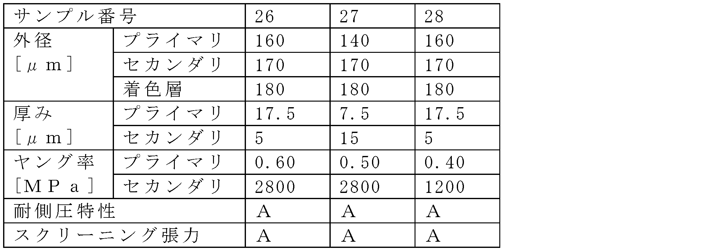


図9は、第3実施形態の変形例として、光ファイバ10Cの軸方向に垂直な断面を示す図である。光ファイバ10Cは、第3実施形態の被覆樹脂層16Bに代えて被覆樹脂層16Cを備える。被覆樹脂層16Cは、第3実施形態の被覆樹脂層16Bの構成に加えて、着色層18(第2の着色層)を更に有する。着色層18は、セカンダリ樹脂層15と着色層17との間に形成され、着色層17とは色が異なる樹脂層である。着色層18は、ガラスファイバ13の軸方向において互いに間隔をあけて形成された複数のリングパターンを含む。着色層18は、例えば溶媒希釈型のインクを射出するインクジェット方式により形成される。溶媒希釈型のインクは、アルコール等による清拭により除去されてしまう性質を有するので、セカンダリ樹脂層15の外側表面に着色層18を形成し、その上に着色層17を形成して着色層18を覆う。着色層18は光ファイバの長さ方向にはその厚さが不連続な層である。光ファイバ10Cを長さ方向に沿って見たときに、着色層18が無い箇所も存在する。
11…コア
12…クラッド
13…ガラスファイバ
14…プライマリ樹脂層
15…セカンダリ樹脂層
16A,16B,16C…被覆樹脂層
17…着色層(第1の着色層)
18…着色層(第2の着色層)
50…光ファイバ製造装置
121…内クラッド
122…トレンチ
123…外クラッド
510…線引炉
512…把持機構
514…炉心管
516…発熱体
518…ガス供給部
522…ファイバ位置測定部
523…冷却装置
524…外径測定部
530…樹脂被覆装置
540…硬化装置
550…搬送部
552…ガイドローラ
552a…直下ローラ
552b…ガイドローラ
552c,552d,552e…スクリーニングローラ
554…キャプスタン
555…振動抑制部
556…ガイドローラ
560…ボビン
590…制御部
G…ガラス母材
GC,RC…中心軸
Claims (10)
- コア及びクラッドを含むガラスファイバであって、前記クラッドは、前記コアの外周を覆う内クラッドと、前記内クラッドの外周を覆うトレンチと、前記トレンチの外周を覆う外クラッドと、を含み、前記内クラッドの屈折率は前記コアの屈折率よりも低く、前記トレンチの屈折率は前記内クラッドの屈折率よりも低く、前記外クラッドの屈折率は前記トレンチの屈折率よりも高く且つ前記コアの屈折率よりも低く、前記コアにはゲルマニウムが添加され、前記内クラッドの平均塩素質量濃度が500ppm以上5000ppm以下であり、前記外クラッドの屈折率に対する前記コアの比屈折率差をΔ1、前記外クラッドの屈折率に対する前記内クラッドの比屈折率差をΔ2、前記外クラッドの屈折率に対する前記トレンチの比屈折率差をΔ3、前記コアの外周の半径をr1、前記内クラッドの外周の半径をr2、前記トレンチの外周の半径をr3としたときに、r2/r1が2.2以上3.6以下であり、r3-r2が3μm以上10μm以下であり、Δ1-Δ2が0.15%以上0.40%以下であり、|Δ2|が0.10%以下であり、Δ3が-0.70%以上-0.10%以下であるガラスファイバを備え、
波長1310nmの光に対するモードフィールド径が8.8μm以上9.6μm以下であり、
直径15mmのマンドレルに巻回されたときの波長1625nmの光に対する曲げ損失が1ターンあたり1.0dB以下であり、
直径30mmのマンドレルに巻回されたときの波長1625nmの光に対する曲げ損失が10ターンあたり0.1dB以下であり、
零分散波長が1300nm以上1324nm以下であり、
ケーブルカットオフ波長が1260nm以下である、光ファイバ。 - 前記光ファイバが直径100mmのマンドレルに巻回されたときの波長1625nmの光に対する曲げ損失が、1ターンあたり1.0×10⁻⁴dB以下である、請求項1に記載の光ファイバ。
- 前記光ファイバの波長1550nmの光に対する波長分散が18.6ps/(nm・km)以下であり、
前記光ファイバの零分散スロープが0.092ps/(nm2・km)以下である、請求項1または請求項2に記載の光ファイバ。 - 前記光ファイバの波長1383nmの光に対する伝送損失が0.35dB/km以下である、請求項1から請求項3のいずれか1項に記載の光ファイバ。
- 前記ガラスファイバの軸方向における外径変動の標準偏差をσとしたとき3σが0.1μm以上0.5μm以下である、請求項1から請求項4のいずれか1項に記載の光ファイバ。
- 前記外クラッドの平均塩素質量濃度が実質的にゼロであり、
前記外クラッドの平均OH質量濃度が5ppm以上500ppm以下である、請求項1から請求項5のいずれか1項に記載の光ファイバ。 - 前記ガラスファイバの外周を被覆する被覆樹脂層であって、前記ガラスファイバに接して前記ガラスファイバを被覆するプライマリ樹脂層と、前記プライマリ樹脂層の外周を被覆するセカンダリ樹脂層と、を有し、前記プライマリ樹脂層の厚さが7.5μm以上17.5μm以下であり、前記プライマリ樹脂層の23℃におけるヤング率が0.10MPa以上0.50MPa以下であり、前記セカンダリ樹脂層の厚さが5.0μm以上17.5μm以下であり、前記セカンダリ樹脂層の外径が165μm以上175μm以下であり、前記セカンダリ樹脂層の23℃におけるヤング率が1200MPa以上2800MPa以下である被覆樹脂層を更に備える、請求項1から請求項6のいずれか1項に記載の光ファイバ。
- 前記ガラスファイバの外周を被覆する被覆樹脂層であって、前記ガラスファイバに接して前記ガラスファイバを被覆するプライマリ樹脂層と、前記プライマリ樹脂層の外周を被覆するセカンダリ樹脂層と、前記セカンダリ樹脂層の外周を被覆する第1の着色層と、を有し、前記プライマリ樹脂層の厚さが7.5μm以上17.5μm以下であり、前記プライマリ樹脂層の23℃におけるヤング率が0.10MPa以上0.60MPa以下であり、前記セカンダリ樹脂層の厚さが5.0μm以上17.5μm以下であり、前記セカンダリ樹脂層の外径が165μm以上175μm以下であり、前記セカンダリ樹脂層の23℃におけるヤング率が1200MPa以上2800MPa以下である被覆樹脂層を更に備える、請求項1から請求項6のいずれか1項に記載の光ファイバ。
- 前記被覆樹脂層は、前記セカンダリ樹脂層と前記第1の着色層との間に形成され、前記第1の着色層とは色が異なり、前記ガラスファイバの軸方向において互いに間隔をあけて形成された複数のリングパターンを含む第2の着色層を更に有する、請求項8に記載の光ファイバ。
- 前記ガラスファイバの軸方向に所定の間隔で設定した複数の測定点において、前記セカンダリ樹脂層の外周を基準とした中心軸からの前記ガラスファイバの偏心量を測定し、前記複数の測定点のそれぞれの位置に対する前記偏心量を示す波形をフーリエ変換することで得たスペクトルにおいて、前記偏心量の振幅の最大値は、6μm以下である、請求項7から請求項9のいずれか1項に記載の光ファイバ。
Priority Applications (4)
| Application Number | Priority Date | Filing Date | Title |
|---|---|---|---|
| EP22864581.8A EP4398008A4 (en) | 2021-08-31 | 2022-08-30 | OPTICAL FIBER |
| US18/686,932 US20240369758A1 (en) | 2021-08-31 | 2022-08-30 | Optical fiber |
| CN202280058367.1A CN118159887A (zh) | 2021-08-31 | 2022-08-30 | 光纤 |
| JP2023545615A JPWO2023032999A1 (ja) | 2021-08-31 | 2022-08-30 |
Applications Claiming Priority (2)
| Application Number | Priority Date | Filing Date | Title |
|---|---|---|---|
| JP2021141607 | 2021-08-31 | ||
| JP2021-141607 | 2021-08-31 |
Publications (1)
| Publication Number | Publication Date |
|---|---|
| WO2023032999A1 true WO2023032999A1 (ja) | 2023-03-09 |
Family
ID=85411286
Family Applications (1)
| Application Number | Title | Priority Date | Filing Date |
|---|---|---|---|
| PCT/JP2022/032650 Ceased WO2023032999A1 (ja) | 2021-08-31 | 2022-08-30 | 光ファイバ |
Country Status (5)
| Country | Link |
|---|---|
| US (1) | US20240369758A1 (ja) |
| EP (1) | EP4398008A4 (ja) |
| JP (1) | JPWO2023032999A1 (ja) |
| CN (1) | CN118159887A (ja) |
| WO (1) | WO2023032999A1 (ja) |
Cited By (5)
| Publication number | Priority date | Publication date | Assignee | Title |
|---|---|---|---|---|
| CN116520480A (zh) * | 2023-03-22 | 2023-08-01 | 上海大学 | 一种沟槽辅助型抗微弯单模光纤 |
| EP4390477A1 (en) * | 2022-12-12 | 2024-06-26 | Sumitomo Electric Industries, Ltd. | Optical fiber |
| WO2025143138A1 (ja) * | 2023-12-28 | 2025-07-03 | 住友電気工業株式会社 | 光ファイバ |
| US12585062B2 (en) | 2023-02-03 | 2026-03-24 | Sumitomo Electric Industries, Ltd. | Optical fiber |
| US12607798B2 (en) | 2023-02-03 | 2026-04-21 | Sumitomo Electric Industries, Ltd. | Optical fiber |
Families Citing this family (1)
| Publication number | Priority date | Publication date | Assignee | Title |
|---|---|---|---|---|
| JP7757664B2 (ja) | 2021-08-31 | 2025-10-22 | 住友電気工業株式会社 | 光ファイバ |
Citations (12)
| Publication number | Priority date | Publication date | Assignee | Title |
|---|---|---|---|---|
| WO2004092794A1 (ja) * | 2003-04-11 | 2004-10-28 | Fujikura Ltd. | 光ファイバ |
| JP2012078804A (ja) * | 2010-09-06 | 2012-04-19 | Shin Etsu Chem Co Ltd | 光ファイバ、光ファイバプリフォームおよびその製造方法 |
| JP2014066558A (ja) * | 2012-09-25 | 2014-04-17 | Fujikura Ltd | 光ファイバの偏肉測定方法、光ファイバの偏肉測定装置、光ファイバの製造方法、光ファイバの製造装置 |
| WO2015174182A1 (ja) * | 2014-05-16 | 2015-11-19 | 住友電気工業株式会社 | テープ心線、および光ケーブル |
| WO2016017743A1 (ja) * | 2014-08-01 | 2016-02-04 | 株式会社フジクラ | 光ファイバ及びその製造方法 |
| JP2018062448A (ja) * | 2016-10-13 | 2018-04-19 | 住友電気工業株式会社 | 光ファイバ心線の製造方法、および光ファイバ心線 |
| JP2018077303A (ja) * | 2016-11-08 | 2018-05-17 | 住友電気工業株式会社 | 光ファイバ心線 |
| WO2020162209A1 (ja) * | 2019-02-07 | 2020-08-13 | 古河電気工業株式会社 | 光ファイバおよび光ファイバの製造方法 |
| US20200310056A1 (en) * | 2019-03-28 | 2020-10-01 | Corning Research & Development Corporation | Colored ribbon with discrete color layers |
| JP2020530586A (ja) * | 2017-08-08 | 2020-10-22 | コーニング インコーポレイテッド | 塩素ドープコアおよびオフセットトレンチを有する低曲げ損失光ファイバ |
| US20210041623A1 (en) | 2019-08-07 | 2021-02-11 | Corning Incorporated | Single mode optical fiber with low bend loss at small and large bend diameters |
| JP2021141607A (ja) | 2020-07-15 | 2021-09-16 | マクセル株式会社 | コンテンツの出力方法 |
Family Cites Families (10)
| Publication number | Priority date | Publication date | Assignee | Title |
|---|---|---|---|---|
| US7271916B2 (en) * | 2002-11-14 | 2007-09-18 | Fitel Usa Corp | Characterization of optical fiber using Fourier domain optical coherence tomography |
| JP5227996B2 (ja) * | 2010-04-05 | 2013-07-03 | 株式会社フジクラ | 光ファイバテープ心線、光ファイバケーブル及び配線形態 |
| KR20130116009A (ko) * | 2012-04-12 | 2013-10-22 | 신에쓰 가가꾸 고교 가부시끼가이샤 | 광섬유 |
| CN105263879B (zh) * | 2013-06-07 | 2018-04-27 | 株式会社藤仓 | 光纤裸线覆盖装置以及光纤裸线覆盖方法 |
| JP6402466B2 (ja) * | 2014-03-31 | 2018-10-10 | 住友電気工業株式会社 | マルチコア光ファイバの製造方法 |
| JP6586870B2 (ja) * | 2015-12-10 | 2019-10-09 | 住友電気工業株式会社 | 光ファイバ心線 |
| US20200189958A1 (en) * | 2017-08-28 | 2020-06-18 | Sumitomo Electric Industries, Ltd. | Manufacturing method of optical fiber |
| JP2019120894A (ja) * | 2018-01-11 | 2019-07-22 | 住友電気工業株式会社 | 光ファイバ、光ファイバ心線および光伝送システム |
| CN112601997B (zh) * | 2018-08-27 | 2023-01-10 | 住友电气工业株式会社 | 带有识别标记的光纤芯线、带有识别标记的光纤芯线的制造方法 |
| EP4090636A1 (en) * | 2020-01-17 | 2022-11-23 | Corning Incorporated | Reduced coating diameter chlorine-doped silica optical fibers with low loss and microbend sensitivity |
-
2022
- 2022-08-30 US US18/686,932 patent/US20240369758A1/en active Pending
- 2022-08-30 JP JP2023545615A patent/JPWO2023032999A1/ja active Pending
- 2022-08-30 CN CN202280058367.1A patent/CN118159887A/zh active Pending
- 2022-08-30 EP EP22864581.8A patent/EP4398008A4/en active Pending
- 2022-08-30 WO PCT/JP2022/032650 patent/WO2023032999A1/ja not_active Ceased
Patent Citations (13)
| Publication number | Priority date | Publication date | Assignee | Title |
|---|---|---|---|---|
| WO2004092794A1 (ja) * | 2003-04-11 | 2004-10-28 | Fujikura Ltd. | 光ファイバ |
| JP2012078804A (ja) * | 2010-09-06 | 2012-04-19 | Shin Etsu Chem Co Ltd | 光ファイバ、光ファイバプリフォームおよびその製造方法 |
| JP2014066558A (ja) * | 2012-09-25 | 2014-04-17 | Fujikura Ltd | 光ファイバの偏肉測定方法、光ファイバの偏肉測定装置、光ファイバの製造方法、光ファイバの製造装置 |
| WO2015174182A1 (ja) * | 2014-05-16 | 2015-11-19 | 住友電気工業株式会社 | テープ心線、および光ケーブル |
| WO2016017743A1 (ja) * | 2014-08-01 | 2016-02-04 | 株式会社フジクラ | 光ファイバ及びその製造方法 |
| JP2018062448A (ja) * | 2016-10-13 | 2018-04-19 | 住友電気工業株式会社 | 光ファイバ心線の製造方法、および光ファイバ心線 |
| JP2018077303A (ja) * | 2016-11-08 | 2018-05-17 | 住友電気工業株式会社 | 光ファイバ心線 |
| JP2020530586A (ja) * | 2017-08-08 | 2020-10-22 | コーニング インコーポレイテッド | 塩素ドープコアおよびオフセットトレンチを有する低曲げ損失光ファイバ |
| WO2020162209A1 (ja) * | 2019-02-07 | 2020-08-13 | 古河電気工業株式会社 | 光ファイバおよび光ファイバの製造方法 |
| JP2020129037A (ja) | 2019-02-07 | 2020-08-27 | 古河電気工業株式会社 | 光ファイバおよび光ファイバの製造方法 |
| US20200310056A1 (en) * | 2019-03-28 | 2020-10-01 | Corning Research & Development Corporation | Colored ribbon with discrete color layers |
| US20210041623A1 (en) | 2019-08-07 | 2021-02-11 | Corning Incorporated | Single mode optical fiber with low bend loss at small and large bend diameters |
| JP2021141607A (ja) | 2020-07-15 | 2021-09-16 | マクセル株式会社 | コンテンツの出力方法 |
Cited By (6)
| Publication number | Priority date | Publication date | Assignee | Title |
|---|---|---|---|---|
| EP4390477A1 (en) * | 2022-12-12 | 2024-06-26 | Sumitomo Electric Industries, Ltd. | Optical fiber |
| US12601871B2 (en) | 2022-12-12 | 2026-04-14 | Sumitomo Electric Industries, Ltd. | Optical fiber |
| US12585062B2 (en) | 2023-02-03 | 2026-03-24 | Sumitomo Electric Industries, Ltd. | Optical fiber |
| US12607798B2 (en) | 2023-02-03 | 2026-04-21 | Sumitomo Electric Industries, Ltd. | Optical fiber |
| CN116520480A (zh) * | 2023-03-22 | 2023-08-01 | 上海大学 | 一种沟槽辅助型抗微弯单模光纤 |
| WO2025143138A1 (ja) * | 2023-12-28 | 2025-07-03 | 住友電気工業株式会社 | 光ファイバ |
Also Published As
| Publication number | Publication date |
|---|---|
| EP4398008A1 (en) | 2024-07-10 |
| CN118159887A (zh) | 2024-06-07 |
| US20240369758A1 (en) | 2024-11-07 |
| JPWO2023032999A1 (ja) | 2023-03-09 |
| EP4398008A4 (en) | 2024-12-25 |
Similar Documents
| Publication | Publication Date | Title |
|---|---|---|
| WO2023032999A1 (ja) | 光ファイバ | |
| JP7757664B2 (ja) | 光ファイバ | |
| US11448842B2 (en) | Small diameter fiber optic cables having low-friction cable jackets and optical fibers with reduced cladding and coating diameters | |
| JP7839597B2 (ja) | 高密度ケーブル及び相互接続のための、薄型コーティングを備えたシングルモード光ファイバ | |
| JP7740806B2 (ja) | 高い機械的信頼性を有する半径の減少した光ファイバ | |
| CN115552298A (zh) | 改善了微弯曲的直径减小的光纤 | |
| US11579359B2 (en) | Reduced diameter multi mode optical fibers with high mechanical reliability | |
| TWI703358B (zh) | 光纖及光纖帶心線 | |
| JP2022521898A (ja) | 耐穿刺性小径マルチモード光ファイバ | |
| US11506835B2 (en) | Optical fiber with low macrobend loss at large bend diameter | |
| CN105393149A (zh) | 低直径光纤 | |
| JP2022521899A (ja) | クラッドの厚さが削減されたマルチモード光ファイバ | |
| US11733453B2 (en) | Reduced diameter single mode optical fibers with high mechanical reliability | |
| US11656403B2 (en) | Single mode optical fibers with low cutoff wavelength high mechanical reliability | |
| CN115516349A (zh) | 改善了微弯曲的直径减小的光纤 | |
| JP2024110717A (ja) | 光ファイバ | |
| JP2024110698A (ja) | 光ファイバ | |
| JP2024083756A (ja) | 光ファイバ | |
| CN112654908A (zh) | 光纤芯线和光纤线缆 | |
| JP2026504970A (ja) | 大きい曲げ直径および小さい曲げ直径での低い曲げ損失、および中程度の有効面積を備えた低い直径の光ファイバ | |
| US12474522B2 (en) | Compliant optical fiber |
Legal Events
| Date | Code | Title | Description |
|---|---|---|---|
| 121 | Ep: the epo has been informed by wipo that ep was designated in this application |
Ref document number: 22864581 Country of ref document: EP Kind code of ref document: A1 |
|
| WWE | Wipo information: entry into national phase |
Ref document number: 2023545615 Country of ref document: JP |
|
| WWE | Wipo information: entry into national phase |
Ref document number: 202280058367.1 Country of ref document: CN |
|
| WWE | Wipo information: entry into national phase |
Ref document number: 2022864581 Country of ref document: EP |
|
| NENP | Non-entry into the national phase |
Ref country code: DE |
|
| ENP | Entry into the national phase |
Ref document number: 2022864581 Country of ref document: EP Effective date: 20240402 |