WO2023038060A1 - 空気調和装置 - Google Patents
空気調和装置 Download PDFInfo
- Publication number
- WO2023038060A1 WO2023038060A1 PCT/JP2022/033584 JP2022033584W WO2023038060A1 WO 2023038060 A1 WO2023038060 A1 WO 2023038060A1 JP 2022033584 W JP2022033584 W JP 2022033584W WO 2023038060 A1 WO2023038060 A1 WO 2023038060A1
- Authority
- WO
- WIPO (PCT)
- Prior art keywords
- refrigerant
- heat exchanger
- region
- valve
- outdoor
- Prior art date
- Legal status (The legal status is an assumption and is not a legal conclusion. Google has not performed a legal analysis and makes no representation as to the accuracy of the status listed.)
- Ceased
Links
Images


Classifications
-
- F—MECHANICAL ENGINEERING; LIGHTING; HEATING; WEAPONS; BLASTING
- F24—HEATING; RANGES; VENTILATING
- F24F—AIR-CONDITIONING; AIR-HUMIDIFICATION; VENTILATION; USE OF AIR CURRENTS FOR SCREENING
- F24F11/00—Control or safety arrangements
- F24F11/30—Control or safety arrangements for purposes related to the operation of the system, e.g. for safety or monitoring
- F24F11/49—Control or safety arrangements for purposes related to the operation of the system, e.g. for safety or monitoring ensuring correct operation, e.g. by trial operation or configuration checks
-
- F—MECHANICAL ENGINEERING; LIGHTING; HEATING; WEAPONS; BLASTING
- F25—REFRIGERATION OR COOLING; COMBINED HEATING AND REFRIGERATION SYSTEMS; HEAT PUMP SYSTEMS; MANUFACTURE OR STORAGE OF ICE; LIQUEFACTION SOLIDIFICATION OF GASES
- F25B—REFRIGERATION MACHINES, PLANTS OR SYSTEMS; COMBINED HEATING AND REFRIGERATION SYSTEMS; HEAT PUMP SYSTEMS
- F25B5/00—Compression machines, plants or systems, with several evaporator circuits, e.g. for varying refrigerating capacity
- F25B5/02—Compression machines, plants or systems, with several evaporator circuits, e.g. for varying refrigerating capacity arranged in parallel
-
- F—MECHANICAL ENGINEERING; LIGHTING; HEATING; WEAPONS; BLASTING
- F24—HEATING; RANGES; VENTILATING
- F24F—AIR-CONDITIONING; AIR-HUMIDIFICATION; VENTILATION; USE OF AIR CURRENTS FOR SCREENING
- F24F1/00—Room units for air-conditioning, e.g. separate or self-contained units or units receiving primary air from a central station
- F24F1/06—Separate outdoor units, e.g. outdoor unit to be linked to a separate room comprising a compressor and a heat exchanger
- F24F1/44—Separate outdoor units, e.g. outdoor unit to be linked to a separate room comprising a compressor and a heat exchanger characterised by the use of internal combustion engines
-
- F—MECHANICAL ENGINEERING; LIGHTING; HEATING; WEAPONS; BLASTING
- F24—HEATING; RANGES; VENTILATING
- F24F—AIR-CONDITIONING; AIR-HUMIDIFICATION; VENTILATION; USE OF AIR CURRENTS FOR SCREENING
- F24F11/00—Control or safety arrangements
- F24F11/70—Control systems characterised by their outputs; Constructional details thereof
- F24F11/80—Control systems characterised by their outputs; Constructional details thereof for controlling the temperature of the supplied air
- F24F11/83—Control systems characterised by their outputs; Constructional details thereof for controlling the temperature of the supplied air by controlling the supply of heat-exchange fluids to heat-exchangers
- F24F11/84—Control systems characterised by their outputs; Constructional details thereof for controlling the temperature of the supplied air by controlling the supply of heat-exchange fluids to heat-exchangers using valves
-
- F—MECHANICAL ENGINEERING; LIGHTING; HEATING; WEAPONS; BLASTING
- F25—REFRIGERATION OR COOLING; COMBINED HEATING AND REFRIGERATION SYSTEMS; HEAT PUMP SYSTEMS; MANUFACTURE OR STORAGE OF ICE; LIQUEFACTION SOLIDIFICATION OF GASES
- F25B—REFRIGERATION MACHINES, PLANTS OR SYSTEMS; COMBINED HEATING AND REFRIGERATION SYSTEMS; HEAT PUMP SYSTEMS
- F25B13/00—Compression machines, plants or systems, with reversible cycle
-
- F—MECHANICAL ENGINEERING; LIGHTING; HEATING; WEAPONS; BLASTING
- F25—REFRIGERATION OR COOLING; COMBINED HEATING AND REFRIGERATION SYSTEMS; HEAT PUMP SYSTEMS; MANUFACTURE OR STORAGE OF ICE; LIQUEFACTION SOLIDIFICATION OF GASES
- F25B—REFRIGERATION MACHINES, PLANTS OR SYSTEMS; COMBINED HEATING AND REFRIGERATION SYSTEMS; HEAT PUMP SYSTEMS
- F25B27/00—Machines, plants or systems, using particular sources of energy
- F25B27/02—Machines, plants or systems, using particular sources of energy using waste heat, e.g. from internal-combustion engines
-
- F—MECHANICAL ENGINEERING; LIGHTING; HEATING; WEAPONS; BLASTING
- F25—REFRIGERATION OR COOLING; COMBINED HEATING AND REFRIGERATION SYSTEMS; HEAT PUMP SYSTEMS; MANUFACTURE OR STORAGE OF ICE; LIQUEFACTION SOLIDIFICATION OF GASES
- F25B—REFRIGERATION MACHINES, PLANTS OR SYSTEMS; COMBINED HEATING AND REFRIGERATION SYSTEMS; HEAT PUMP SYSTEMS
- F25B41/00—Fluid-circulation arrangements
- F25B41/20—Disposition of valves, e.g. of on-off valves or flow control valves
-
- F—MECHANICAL ENGINEERING; LIGHTING; HEATING; WEAPONS; BLASTING
- F25—REFRIGERATION OR COOLING; COMBINED HEATING AND REFRIGERATION SYSTEMS; HEAT PUMP SYSTEMS; MANUFACTURE OR STORAGE OF ICE; LIQUEFACTION SOLIDIFICATION OF GASES
- F25B—REFRIGERATION MACHINES, PLANTS OR SYSTEMS; COMBINED HEATING AND REFRIGERATION SYSTEMS; HEAT PUMP SYSTEMS
- F25B49/00—Arrangement or mounting of control or safety devices
- F25B49/02—Arrangement or mounting of control or safety devices for compression type machines, plants or systems
-
- F—MECHANICAL ENGINEERING; LIGHTING; HEATING; WEAPONS; BLASTING
- F25—REFRIGERATION OR COOLING; COMBINED HEATING AND REFRIGERATION SYSTEMS; HEAT PUMP SYSTEMS; MANUFACTURE OR STORAGE OF ICE; LIQUEFACTION SOLIDIFICATION OF GASES
- F25B—REFRIGERATION MACHINES, PLANTS OR SYSTEMS; COMBINED HEATING AND REFRIGERATION SYSTEMS; HEAT PUMP SYSTEMS
- F25B2313/00—Compression machines, plants or systems with reversible cycle not otherwise provided for
- F25B2313/004—Outdoor unit with water as a heat sink or heat source
-
- F—MECHANICAL ENGINEERING; LIGHTING; HEATING; WEAPONS; BLASTING
- F25—REFRIGERATION OR COOLING; COMBINED HEATING AND REFRIGERATION SYSTEMS; HEAT PUMP SYSTEMS; MANUFACTURE OR STORAGE OF ICE; LIQUEFACTION SOLIDIFICATION OF GASES
- F25B—REFRIGERATION MACHINES, PLANTS OR SYSTEMS; COMBINED HEATING AND REFRIGERATION SYSTEMS; HEAT PUMP SYSTEMS
- F25B2313/00—Compression machines, plants or systems with reversible cycle not otherwise provided for
- F25B2313/025—Compression machines, plants or systems with reversible cycle not otherwise provided for using multiple outdoor units
- F25B2313/0252—Compression machines, plants or systems with reversible cycle not otherwise provided for using multiple outdoor units with bypasses
-
- F—MECHANICAL ENGINEERING; LIGHTING; HEATING; WEAPONS; BLASTING
- F25—REFRIGERATION OR COOLING; COMBINED HEATING AND REFRIGERATION SYSTEMS; HEAT PUMP SYSTEMS; MANUFACTURE OR STORAGE OF ICE; LIQUEFACTION SOLIDIFICATION OF GASES
- F25B—REFRIGERATION MACHINES, PLANTS OR SYSTEMS; COMBINED HEATING AND REFRIGERATION SYSTEMS; HEAT PUMP SYSTEMS
- F25B2313/00—Compression machines, plants or systems with reversible cycle not otherwise provided for
- F25B2313/025—Compression machines, plants or systems with reversible cycle not otherwise provided for using multiple outdoor units
- F25B2313/0253—Compression machines, plants or systems with reversible cycle not otherwise provided for using multiple outdoor units in parallel arrangements
-
- F—MECHANICAL ENGINEERING; LIGHTING; HEATING; WEAPONS; BLASTING
- F25—REFRIGERATION OR COOLING; COMBINED HEATING AND REFRIGERATION SYSTEMS; HEAT PUMP SYSTEMS; MANUFACTURE OR STORAGE OF ICE; LIQUEFACTION SOLIDIFICATION OF GASES
- F25B—REFRIGERATION MACHINES, PLANTS OR SYSTEMS; COMBINED HEATING AND REFRIGERATION SYSTEMS; HEAT PUMP SYSTEMS
- F25B2313/00—Compression machines, plants or systems with reversible cycle not otherwise provided for
- F25B2313/025—Compression machines, plants or systems with reversible cycle not otherwise provided for using multiple outdoor units
- F25B2313/0254—Compression machines, plants or systems with reversible cycle not otherwise provided for using multiple outdoor units in series arrangements
-
- F—MECHANICAL ENGINEERING; LIGHTING; HEATING; WEAPONS; BLASTING
- F25—REFRIGERATION OR COOLING; COMBINED HEATING AND REFRIGERATION SYSTEMS; HEAT PUMP SYSTEMS; MANUFACTURE OR STORAGE OF ICE; LIQUEFACTION SOLIDIFICATION OF GASES
- F25B—REFRIGERATION MACHINES, PLANTS OR SYSTEMS; COMBINED HEATING AND REFRIGERATION SYSTEMS; HEAT PUMP SYSTEMS
- F25B2313/00—Compression machines, plants or systems with reversible cycle not otherwise provided for
- F25B2313/027—Compression machines, plants or systems with reversible cycle not otherwise provided for characterised by the reversing means
- F25B2313/02741—Compression machines, plants or systems with reversible cycle not otherwise provided for characterised by the reversing means using one four-way valve
-
- F—MECHANICAL ENGINEERING; LIGHTING; HEATING; WEAPONS; BLASTING
- F25—REFRIGERATION OR COOLING; COMBINED HEATING AND REFRIGERATION SYSTEMS; HEAT PUMP SYSTEMS; MANUFACTURE OR STORAGE OF ICE; LIQUEFACTION SOLIDIFICATION OF GASES
- F25B—REFRIGERATION MACHINES, PLANTS OR SYSTEMS; COMBINED HEATING AND REFRIGERATION SYSTEMS; HEAT PUMP SYSTEMS
- F25B2313/00—Compression machines, plants or systems with reversible cycle not otherwise provided for
- F25B2313/031—Sensor arrangements
- F25B2313/0314—Temperature sensors near the indoor heat exchanger
-
- F—MECHANICAL ENGINEERING; LIGHTING; HEATING; WEAPONS; BLASTING
- F25—REFRIGERATION OR COOLING; COMBINED HEATING AND REFRIGERATION SYSTEMS; HEAT PUMP SYSTEMS; MANUFACTURE OR STORAGE OF ICE; LIQUEFACTION SOLIDIFICATION OF GASES
- F25B—REFRIGERATION MACHINES, PLANTS OR SYSTEMS; COMBINED HEATING AND REFRIGERATION SYSTEMS; HEAT PUMP SYSTEMS
- F25B2327/00—Refrigeration system using an engine for driving a compressor
- F25B2327/001—Refrigeration system using an engine for driving a compressor of the internal combustion type
-
- F—MECHANICAL ENGINEERING; LIGHTING; HEATING; WEAPONS; BLASTING
- F25—REFRIGERATION OR COOLING; COMBINED HEATING AND REFRIGERATION SYSTEMS; HEAT PUMP SYSTEMS; MANUFACTURE OR STORAGE OF ICE; LIQUEFACTION SOLIDIFICATION OF GASES
- F25B—REFRIGERATION MACHINES, PLANTS OR SYSTEMS; COMBINED HEATING AND REFRIGERATION SYSTEMS; HEAT PUMP SYSTEMS
- F25B2400/00—General features or devices for refrigeration machines, plants or systems, combined heating and refrigeration systems or heat-pump systems, i.e. not limited to a particular subgroup of F25B
- F25B2400/04—Refrigeration circuit bypassing means
- F25B2400/0401—Refrigeration circuit bypassing means for the compressor
-
- F—MECHANICAL ENGINEERING; LIGHTING; HEATING; WEAPONS; BLASTING
- F25—REFRIGERATION OR COOLING; COMBINED HEATING AND REFRIGERATION SYSTEMS; HEAT PUMP SYSTEMS; MANUFACTURE OR STORAGE OF ICE; LIQUEFACTION SOLIDIFICATION OF GASES
- F25B—REFRIGERATION MACHINES, PLANTS OR SYSTEMS; COMBINED HEATING AND REFRIGERATION SYSTEMS; HEAT PUMP SYSTEMS
- F25B2500/00—Problems to be solved
- F25B2500/16—Lubrication
-
- F—MECHANICAL ENGINEERING; LIGHTING; HEATING; WEAPONS; BLASTING
- F25—REFRIGERATION OR COOLING; COMBINED HEATING AND REFRIGERATION SYSTEMS; HEAT PUMP SYSTEMS; MANUFACTURE OR STORAGE OF ICE; LIQUEFACTION SOLIDIFICATION OF GASES
- F25B—REFRIGERATION MACHINES, PLANTS OR SYSTEMS; COMBINED HEATING AND REFRIGERATION SYSTEMS; HEAT PUMP SYSTEMS
- F25B2600/00—Control issues
- F25B2600/02—Compressor control
-
- F—MECHANICAL ENGINEERING; LIGHTING; HEATING; WEAPONS; BLASTING
- F25—REFRIGERATION OR COOLING; COMBINED HEATING AND REFRIGERATION SYSTEMS; HEAT PUMP SYSTEMS; MANUFACTURE OR STORAGE OF ICE; LIQUEFACTION SOLIDIFICATION OF GASES
- F25B—REFRIGERATION MACHINES, PLANTS OR SYSTEMS; COMBINED HEATING AND REFRIGERATION SYSTEMS; HEAT PUMP SYSTEMS
- F25B2600/00—Control issues
- F25B2600/25—Control of valves
- F25B2600/2515—Flow valves
-
- F—MECHANICAL ENGINEERING; LIGHTING; HEATING; WEAPONS; BLASTING
- F25—REFRIGERATION OR COOLING; COMBINED HEATING AND REFRIGERATION SYSTEMS; HEAT PUMP SYSTEMS; MANUFACTURE OR STORAGE OF ICE; LIQUEFACTION SOLIDIFICATION OF GASES
- F25B—REFRIGERATION MACHINES, PLANTS OR SYSTEMS; COMBINED HEATING AND REFRIGERATION SYSTEMS; HEAT PUMP SYSTEMS
- F25B2600/00—Control issues
- F25B2600/25—Control of valves
- F25B2600/2519—On-off valves
-
- Y—GENERAL TAGGING OF NEW TECHNOLOGICAL DEVELOPMENTS; GENERAL TAGGING OF CROSS-SECTIONAL TECHNOLOGIES SPANNING OVER SEVERAL SECTIONS OF THE IPC; TECHNICAL SUBJECTS COVERED BY FORMER USPC CROSS-REFERENCE ART COLLECTIONS [XRACs] AND DIGESTS
- Y02—TECHNOLOGIES OR APPLICATIONS FOR MITIGATION OR ADAPTATION AGAINST CLIMATE CHANGE
- Y02A—TECHNOLOGIES FOR ADAPTATION TO CLIMATE CHANGE
- Y02A30/00—Adapting or protecting infrastructure or their operation
- Y02A30/27—Relating to heating, ventilation or air conditioning [HVAC] technologies
- Y02A30/274—Relating to heating, ventilation or air conditioning [HVAC] technologies using waste energy, e.g. from internal combustion engine
Definitions
- the present disclosure relates to a gas heat pump air conditioner in which a compressor that compresses refrigerant is driven by a gas engine.
- Patent Document 1 discloses a parallel flow heat exchanger that can obtain a suitable refrigerant distribution as a condenser and an evaporator, and can obtain a sufficient amount of heat exchange.
- This heat exchanger is constructed such that the in-pipe cross-sectional area of the upper header pipe is 1.4 times or more as large as the in-pipe cross-sectional area of the lower header pipe.
- the present disclosure provides a gas heat pump air conditioner (hereinafter referred to as GHP) that can prevent refrigerating machine oil from staying in the heat exchanger when the heat exchanger is used as an evaporator.
- GHP gas heat pump air conditioner
- the outdoor heat exchanger includes a first region and a second region in which refrigerant flows in parallel to each other, It is characterized by comprising an on-off valve provided at a refrigerant inflow part on the side of the flow control valve in the first region.
- the refrigerant flow path is switched to only the second region by closing the on-off valve, so the cross-sectional area of the refrigerant flow path is reduced.
- Refrigerant flow velocity increases. That is, the greater the speed difference between the refrigerant and the refrigerating machine oil, the greater the shearing force applied to the refrigerating machine oil in the vertically upward direction. Therefore, since the refrigerating machine oil can rise up the heat transfer tubes, it is possible to prevent stagnation of the refrigerating machine oil in the heat exchanger.
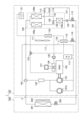
- FIG. 1 is a diagram showing a refrigerant channel and a cooling water channel of an air conditioner according to Embodiment 1 of the present disclosure.
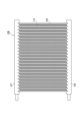
- FIG. 2 is a diagram showing a configuration of an outdoor heat exchanger according to Embodiment 1 of the present disclosure;
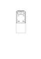
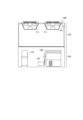
- FIG. 3A is a side view of the outdoor unit according to Embodiment 1 of the present disclosure;
- 3B is a front view of the outdoor unit according to Embodiment 1 of the present disclosure;
- FIG. 3C is a top view of the outdoor unit according to Embodiment 1 of the present disclosure;
- FIG. FIG. 4 is a diagram showing refrigerant channels and cooling water channels of an air conditioner according to Embodiment 2 of the present disclosure.
- FIG. 5 is a diagram showing a refrigerant channel and a cooling water channel of an air conditioner in Example 1 of another embodiment of the present disclosure
- FIG. 6 is a diagram showing a refrigerant channel and a cooling water channel of an air conditioner in Example 2 of another embodiment of the present disclosure
- FIG. 7A is a side view of an outdoor unit in Example 3 of another embodiment of the present disclosure
- FIG. 7B is a front view of an outdoor unit in Example 3 of another embodiment of the present disclosure
- FIG. 7C is a top view of an outdoor unit in Example 3 of another embodiment of the present disclosure
- the pressure loss in the upper header pipe serving as the refrigerant vapor outlet and the pressure loss in the lower header pipe serving as the liquid refrigerant inlet are approximately the same, and the static pressure difference between the upper and lower headers is substantially constant regardless of the heat transfer tubes. Therefore, the refrigerant distribution becomes uniform and a sufficient amount of heat exchange can be obtained.
- the refrigerating machine oil dissolves in the refrigerant and rises vertically in the heat transfer tube.
- the heat transfer tube rises due to the shear force caused by the speed difference with the phase refrigerant, but when the speed of the gas phase refrigerant is slow such as during low load operation, the heat transfer tube cannot rise and stays in the heat exchanger.
- the inventors came up with the idea of increasing the flow velocity of the refrigerant to increase the shear force caused by the difference in velocity between the refrigerant and the refrigerating machine oil so that the refrigerating machine oil can rise up the heat transfer tubes. .
- the outdoor heat exchanger is provided with a first region and a second region in which the refrigerant flows parallel to each other, and when used as an evaporator, the on-off valve is switched so that the refrigerant flows only in the second region. , to provide a GHP that can increase the refrigerant flow rate and allow the refrigerating machine oil to rise through the heat transfer tubes.
- an air conditioner 1 is composed of an outdoor unit 100 and an indoor unit 200 , and the indoor unit 200 is connected to a unit pipe 2 extending from the outdoor unit 100 .
- Each device of the indoor unit 200 and the outdoor unit 100 is connected by refrigerant pipes to form a refrigerant circuit.
- the compressor 101 is connected to the gas engine 102 by power transmission means such as a belt.
- the oil separator 103 is installed in the discharge pipe of the compressor 101 and separates refrigerating machine oil contained in the refrigerant gas discharged from the compressor 101 .
- the oil separated by the oil separator 103 is returned to the suction pipe of the compressor 101 through an oil return pipe (not shown).
- the four-way valve 104 is for switching the refrigeration cycle between cooling and heating, and FIG. 1 shows the flow during heating.
- the refrigerant liquid pipe 105 connects the outdoor heat exchanger 106 and the indoor heat exchanger 201 .
- the outdoor heat exchanger 106 is composed of heat transfer tubes 109 connected at both ends to a pair of horizontally opposed upper and lower header pipes 107 and 108, respectively.
- the upper header pipe 107 and the lower header pipe 108 each have a coolant inlet.
- the heat transfer tubes 109 are arranged in parallel in the vertical direction, and heat transfer fins 110 are provided therebetween.
- the outdoor heat exchanger 106 includes a first region 106a and a second region 106b in which the refrigerant flows parallel to each other. , absorbs heat from outside air during heating operation.
- the outdoor flow control valve (flow control valve) 112 is provided in the refrigerant liquid pipe 105 and adjusts the pressure and flow rate of the refrigerant.
- the first on-off valve (on-off valve) 113 is provided in the refrigerant inflow part on the side of the outdoor flow control valve 112 in the first area 106a, and opens and closes the refrigerant flow path.
- Accumulator 115 is connected to a suction pipe of compressor 101 and supplies gas refrigerant to compressor 101 .
- the exhaust heat recovery bypass pipe 116 has one end connected to the upstream side of the accumulator 115 of the low-pressure gas pipe 117, the other end connected to the refrigerant liquid pipe 105, and the exhaust heat recovery flow rate adjustment valve 118, In addition, an exhaust heat recovery heat exchanger 119 is provided, and during heating operation, the refrigerant can also absorb heat from cooling water, which will be described later.
- the indoor heat exchanger 201 absorbs indoor heat by the indoor fan 202 during cooling operation, and radiates the heat of the refrigerant indoors during heating operation.
- the indoor flow control valve 203 adjusts the pressure and flow rate of the refrigerant.
- a cooling water flow path indicated by a broken line in FIG. 1 includes a cooling water pump 120, a reservoir tank 121, a radiator 122, a three-way valve 123, and an exhaust heat recovery heat exchanger 119.
- a circuit configured by these This is a flow path for cooling the gas engine 102 with cooling water circulating through.
- a cooling water pump 120 circulates cooling water for the gas engine 102 in the circuit.
- the reservoir tank 121 temporarily stores the surplus cooling water in order to make up for the shortage of the cooling water.
- the radiator 122 uses the outdoor fan 111 to radiate the heat of the cooling water. The arrangement of radiator 122 will be described later.
- the three-way valve 123 can switch the flow path of the cooling water to the radiator 122 side, the exhaust heat recovery heat exchanger 119 side, or both the radiator 122 and the exhaust heat recovery heat exchanger 119. flows part of the cooling water to the radiator 122 and the rest of the cooling water to the exhaust heat recovery heat exchanger 119 during heating operation to the radiator 122 side, so that the temperature of the cooling water returning to the gas engine 102 is kept substantially constant. control to maintain As described above, the exhaust heat recovery heat exchanger 119 circulates the refrigerant and the cooling water so that the refrigerant absorbs the heat of the cooling water.
- the outdoor unit 100 includes a compressor 101, a gas engine 102, an accumulator 115, an oil separator (not shown), a four-way valve, a flow control valve, an exhaust heat recovery heat exchanger, and the like. is provided below the outdoor unit 100, and a heat exchanger room 125 including the outdoor heat exchanger 106, the outdoor fan 111, the reservoir tank 121, etc. is provided above the outdoor unit 100.
- a heat exchanger room 125 including the outdoor heat exchanger 106, the outdoor fan 111, the reservoir tank 121, etc. is provided above the outdoor unit 100.
- the first area 106 a is arranged on the front side of the housing of the outdoor unit 100 .
- the second area 106b is arranged on the back side of the housing of the outdoor unit 100 .
- the function of each element is as described above.
- the outdoor unit 100 has a control section (not shown).
- the control unit includes, for example, a processor such as a CPU or MPU that executes programs, and memory such as ROM and RAM. Various processes are executed by cooperation of As an example, in the present embodiment, the control unit controls switching between opening and closing of the first on-off valve 113 .
- the liquid refrigerant that has passed through the first region 106a passes through the first on-off valve 113, joins the refrigerant that has passed through the second region 106b, and is supplied to the indoor unit 200 after passing through the outdoor flow control valve 112. .
- the high-pressure liquid refrigerant that has flowed into the indoor unit 200 is decompressed by the indoor flow control valve 203 , becomes a gas-liquid two-phase state, and flows into the indoor heat exchanger 201 .
- the gas-liquid two-phase refrigerant exchanges heat with the air in the space to be air-conditioned in the indoor heat exchanger 201 , absorbs heat, evaporates, and flows out of the indoor unit 200 as a low-pressure gas refrigerant.
- the low-pressure gas refrigerant that has flowed out of the indoor unit 200 flows into the outdoor unit 100 again.
- the gas refrigerant that has flowed into the outdoor unit 100 passes through the four-way valve 104 and the accumulator 115, returns to the compressor 101, and repeats the above process.
- the oil separated by the oil separator 103 flows through an oil return pipe (not shown) into the suction pipe of the compressor, returns to the compressor 101, and repeats the above process.
- the high-pressure gas refrigerant that has flowed into the indoor unit 200 flows into the indoor heat exchanger 201, exchanges heat with the air in the space to be air-conditioned, and condenses after radiating heat. Then, it becomes a high-pressure liquid refrigerant, passes through the indoor flow control valve 203 , and flows out of the indoor unit 200 .
- the high-pressure liquid refrigerant that has flowed out of the indoor unit 200 flows into the outdoor unit 100 again.
- a part of the liquid refrigerant that has flowed into the outdoor unit 100 flows into the exhaust heat recovery bypass pipe 116, and the remaining liquid refrigerant is decompressed by the outdoor flow rate control valve 112, becomes a gas-liquid two-phase state, and heats the outdoor unit. It flows into the first region 106a and the second region 106b of the exchanger 106 .
- the liquid refrigerant that has flowed into the exhaust heat recovery bypass pipe 116 is decompressed by the exhaust heat recovery flow rate adjustment valve 118 and enters the exhaust heat recovery heat exchanger 119 in a gas-liquid two-phase state.
- the gas-liquid two-phase refrigerant that has flowed into the exhaust heat recovery heat exchanger 119 evaporates after absorbing heat from engine cooling water, which will be described later, and becomes a low-temperature, low-pressure gas refrigerant.
- the gas-liquid two-phase refrigerant that has flowed into the first region 106a and the second region 106b of the outdoor heat exchanger 106 exchanges heat with the outside air to absorb heat, and then evaporates to become a low-pressure gas refrigerant.
- the low-pressure gas refrigerant merges, passes through the four-way valve 104, and in the process of passing through the low-pressure gas pipe 117, merges with the low-temperature, low-pressure gas refrigerant evaporated in the exhaust heat recovery heat exchanger 119, and passes through the accumulator 115. , return to the compressor 101 and repeat the above process. Also, the oil separated by the oil separator 103 flows through an oil return pipe (not shown) into the suction pipe of the compressor, returns to the compressor 101, and repeats the above process.
- the high-pressure gas refrigerant that has flowed into the indoor unit 200 flows into the indoor heat exchanger 201, exchanges heat with the air in the space to be air-conditioned, and condenses after radiating heat. Then, it becomes a high-pressure liquid refrigerant, passes through the indoor flow control valve 203 , and flows out of the indoor unit 200 .
- the high-pressure liquid refrigerant that has flowed out of the indoor unit 200 flows into the outdoor unit 100 again.
- a part of the liquid refrigerant that has flowed into the outdoor unit 100 flows into the exhaust heat recovery bypass pipe 116, and the remaining liquid refrigerant is decompressed by the outdoor flow rate control valve 112, becomes a gas-liquid two-phase state, and heats the outdoor unit. It flows into the second region 106b of the exchanger 106.
- the liquid refrigerant that has flowed into the exhaust heat recovery bypass pipe 116 is decompressed by the exhaust heat recovery flow rate adjustment valve 118 and enters the exhaust heat recovery heat exchanger 119 in a gas-liquid two-phase state.
- the gas-liquid two-phase refrigerant that has flowed into the exhaust heat recovery heat exchanger 119 evaporates after absorbing heat from engine cooling water, which will be described later, and becomes a low-temperature, low-pressure gas refrigerant.
- the gas-liquid two-phase refrigerant that has flowed into the second region 106b of the outdoor heat exchanger 106 exchanges heat with the outside air to absorb heat, and then evaporates to become a low-pressure gas refrigerant.
- the low-pressure gas refrigerant merges with the low-temperature and low-pressure gas refrigerant evaporated in the exhaust heat recovery heat exchanger 119, passes through the accumulator 115, and is compressed. Return to machine 101 and repeat the above process. Also, the oil separated by the oil separator 103 flows through an oil return pipe (not shown) into the suction pipe of the compressor, returns to the compressor 101, and repeats the above process.
- the cooling water pushed out by the cooling water pump 120 flows into the exhaust gas heat exchanger 126 and cools the exhaust gas of the gas engine 102 .
- the exhaust gas cooled by the exhaust gas heat exchanger 126 is released from the exhaust gas muffler 127 to the outside air.
- the cooling water that has passed through the exhaust gas heat exchanger 126 flows into the gas engine 102 and cools the gas engine 102 .
- the cooling water that has cooled the gas engine 102 flows into the three-way valve 123 .
- the three-way valve 123 is controlled in the direction in which the cooling water from the gas engine 102 flows to the radiator 122 .
- the three-way valve 123 serves to flow cooling water to both the radiator 122 and the exhaust heat recovery heat exchanger 119 .
- the cooling water that has flowed into the radiator 122 is cooled by the introduced outside air in the outdoor unit 100, returns to the cooling water pump 120 again, and repeats the above process.
- the cooling water that has flowed into the exhaust heat recovery heat exchanger 119 is cooled by the gas-liquid two-phase refrigerant depressurized by the indoor flow rate control valve 203, returns to the cooling water pump 120 again, and repeats the above process.
- the cooling water outlet temperature of the gas engine 102 is monitored by an outdoor unit control section (not shown), and the rotational speed of the cooling water pump 120 is controlled so as to keep the temperature substantially constant.
- the air conditioner 1 includes the compressor 101, the indoor heat exchanger 201, the indoor flow rate adjustment valve 203, the outdoor flow rate adjustment valve 112, and the outdoor heat exchanger 106 in this order in an annular manner. is connected, a refrigerant is circulated in the piping, heat is exchanged with the air in a predetermined space in the indoor heat exchanger 201, and the temperature of the predetermined space is controlled. It includes a first region 106a and a second region 106b that flow parallel to each other, and a first on-off valve 113 provided at a refrigerant inflow portion of the first region 106a on the indoor flow rate control valve 203 side.
- the refrigerant flow path is switched to only the second region 106b, so that the flow path cross-sectional area of the refrigerant decreases and the flow velocity of the refrigerant increases. That is, the greater the speed difference between the refrigerant and the refrigerating machine oil, the greater the shearing force applied to the refrigerating machine oil in the vertically upward direction. Therefore, since the refrigerating machine oil can rise up the heat transfer tubes 109, it is possible to prevent stagnation of the refrigerating machine oil in the heat exchanger.
- the refrigerant is circulated only in the second region 106b, so the heat transfer area and the amount of air passing through the refrigerant circulating portion are reduced.
- the amount of heat exchanged Q in a heat exchanger is given by Equation 1, where K is the heat transfer rate of the heat exchanger, A is the heat transfer area, and ⁇ T is the temperature difference between fluids that exchange heat.
- Q K ⁇ A ⁇ T (Equation 1)
- the heat transfer area A and the amount of passing air are decreased, so that the heat transfer rate K is decreased, and thus the heat exchange amount Q is decreased.
- the exhaust heat recovery heat exchanger 119 since the exhaust heat recovery heat exchanger 119 is provided, as described above, part of the refrigerant absorbs heat by exchanging heat with the cooling water in the exhaust heat recovery heat exchanger 119 during heating operation, resulting in a shortage.
- the amount of heat exchange can be compensated. In other words, the required amount of heat can be exchanged even during the low-load heating operation.
- the air conditioner 1 according to Embodiment 2 includes the third region 106c of the outdoor heat exchanger 106, the junction portion 128, the first check valve 129, the second check valve 130, the first It differs from the air conditioner 1 according to Embodiment 1 in that a bypass pipe 131, a second bypass pipe 132, and a second on-off valve 114 are provided.
- the outdoor heat exchanger 106 is composed of heat transfer tubes 109 connected at both ends to a pair of horizontally opposed upper and lower header pipes 107 and 108, and the refrigerant flows parallel to each other. It has a first area 106a, a second area 106b, and a third area 106c, and the outdoor fan 111 radiates the heat of the refrigerant to the outside during the cooling operation and absorbs the heat of the outside air during the heating operation.
- the front surface area of outdoor heat exchanger 106 in the present embodiment is assumed to be the same as the front surface area of outdoor heat exchanger 106 in the first embodiment.
- the confluence portion 128 includes a refrigerant inflow portion on the side of the outdoor flow rate adjustment valve 112 in the first region 106a, a refrigerant inflow portion on the side of the outdoor flow rate adjustment valve 112 in the second region 106b, and a refrigerant on the side of the four-way valve 104 in the third region 106c. Connect the inlets.
- the first check valve 129 is provided at the refrigerant outflow portion on the outdoor flow control valve 112 side of the first region 106a.
- the second check valve 130 is provided at the refrigerant outflow portion on the outdoor flow control valve 112 side of the third region 106c.
- the first bypass pipe 131 has one end connected between the second check valve 130 and the outdoor flow control valve 112 in the refrigerant inflow portion on the outdoor flow control valve 112 side of the third region 106c, and the other end connected to the first region 106a. is connected between the first check valve 129 and the first region 106a in the refrigerant inflow portion on the outdoor flow rate adjustment valve 112 side of the .
- the second bypass pipe 132 has one end connected to the first bypass pipe 131 and the other end connected to the refrigerant inflow portion of the second region 106b on the side of the outdoor flow control valve 112 .
- the first on-off valve 113 is provided between the connecting portion of the first bypass pipe 131 and the second bypass pipe 132 and the connecting portion of the first region 106a to the refrigerant inflow portion on the outdoor flow control valve 112 side, and the refrigerant Adjust pressure and flow rate.
- the second on-off valve 114 is provided in the second bypass pipe 132 and adjusts the pressure and flow rate of the refrigerant.
- the outdoor unit 100 has a control section (not shown).
- the control unit includes, for example, a processor such as a CPU or MPU that executes programs, and memory such as ROM and RAM. Various processes are executed by cooperation of As an example, in the present embodiment, the control unit controls switching between opening and closing of the first on-off valve 113 and the second on-off valve 114 .
- the condensed high-pressure liquid refrigerant passes through the confluence portion 128, flows into the third region 106c, exchanges heat with the outside air, and further dissipates heat. Then, it passes through the second check valve 130 and the outdoor flow control valve 112 and is supplied to the indoor unit 200 .
- the high-pressure liquid refrigerant that has flowed into the indoor unit 200 is decompressed by the indoor flow control valve 203 , becomes a gas-liquid two-phase state, and flows into the indoor heat exchanger 201 .
- the gas-liquid two-phase refrigerant exchanges heat with the air in the space to be air-conditioned in the indoor heat exchanger 201 , absorbs heat, evaporates, and flows out of the indoor unit 200 as a low-pressure gas refrigerant.
- the low-pressure gas refrigerant that has flowed out of the indoor unit 200 flows into the outdoor unit 100 again.
- the gas refrigerant that has flowed into the outdoor unit 100 passes through the four-way valve 104 and the accumulator 115, returns to the compressor 101, and repeats the above process.
- the oil separated by the oil separator 103 flows through an oil return pipe (not shown) into the suction pipe of the compressor, returns to the compressor 101, and repeats the above process.
- the high-pressure gas refrigerant that has flowed into the indoor unit 200 flows into the indoor heat exchanger 201, exchanges heat with the air in the space to be air-conditioned, and condenses after radiating heat. Then, it becomes a high-pressure liquid refrigerant, passes through the indoor flow control valve 203 , and flows out of the indoor unit 200 .
- the high-pressure liquid refrigerant that has flowed out of the indoor unit 200 flows into the outdoor unit 100 again.
- Part of the liquid refrigerant that has flowed into the outdoor unit 100 flows into the exhaust heat recovery bypass pipe 116, and the remaining liquid refrigerant is decompressed by the outdoor flow control valve 112, becomes a gas-liquid two-phase state, and enters the first It flows into bypass pipe 131 .
- Part of the gas-liquid two-phase refrigerant that has flowed into the first bypass pipe 131 passes through the first on-off valve 113 and flows into the first region 106a. It passes through the on-off valve 114 and flows into the second region 106b.
- the liquid refrigerant that has flowed into the exhaust heat recovery bypass pipe 116 is decompressed by the exhaust heat recovery flow rate adjustment valve 118 and enters the exhaust heat recovery heat exchanger 119 in a gas-liquid two-phase state.
- the gas-liquid two-phase refrigerant that has flowed into the exhaust heat recovery heat exchanger 119 absorbs heat from the engine cooling water and then evaporates to become a low-temperature, low-pressure gas refrigerant.
- the gas-liquid two-phase refrigerant that has flowed into the first region 106a and the second region 106b of the outdoor heat exchanger 106 exchanges heat with the outside air to absorb heat, and then evaporates to become a low-pressure gas refrigerant. .
- the low-pressure gas refrigerant merges, passes through the four-way valve 104, and in the process of passing through the low-pressure gas pipe 117, merges with the low-temperature, low-pressure gas refrigerant evaporated in the exhaust heat recovery heat exchanger 119, and passes through the accumulator 115. , return to the compressor 101 and repeat the above process. Also, the oil separated by the oil separator 103 flows through an oil return pipe (not shown) into the suction pipe of the compressor, returns to the compressor 101, and repeats the above process.
- the high-pressure gas refrigerant that has flowed into the indoor unit 200 flows into the indoor heat exchanger 201, exchanges heat with the air in the space to be air-conditioned, and condenses after radiating heat. Then, it becomes a high-pressure liquid refrigerant, passes through the indoor flow control valve 203 , and flows out of the indoor unit 200 .
- the high-pressure liquid refrigerant that has flowed out of the indoor unit 200 flows into the outdoor unit 100 again.
- Part of the liquid refrigerant that has flowed into the outdoor unit 100 flows into the exhaust heat recovery bypass pipe 116, and the remaining liquid refrigerant is decompressed by the outdoor flow control valve 112, becomes a gas-liquid two-phase state, and enters the first It passes through the bypass pipe 131 and the second on-off valve 114 and flows into the second region 106 b of the outdoor heat exchanger 106 .
- the liquid refrigerant that has flowed into the exhaust heat recovery bypass pipe 116 is decompressed by the exhaust heat recovery flow rate adjustment valve 118 and enters the exhaust heat recovery heat exchanger 119 in a gas-liquid two-phase state.
- the gas-liquid two-phase refrigerant that has flowed into the exhaust heat recovery heat exchanger 119 absorbs heat from the engine cooling water and then evaporates to become a low-temperature, low-pressure gas refrigerant.
- the gas-liquid two-phase refrigerant that has flowed into the second region 106b of the outdoor heat exchanger 106 exchanges heat with the outside air to absorb heat, and then evaporates to become a low-pressure gas refrigerant.
- the low-pressure gas refrigerant merges with the low-temperature and low-pressure gas refrigerant evaporated in the exhaust heat recovery heat exchanger 119, passes through the accumulator 115, and is compressed.
- the oil separated by the oil separator 103 flows through an oil return pipe (not shown) into the suction pipe of the compressor, returns to the compressor 101, and repeats the above process.
- the air conditioner 1 includes the third region 106c of the outdoor heat exchanger 106, the confluence portion 128, the first check valve 129, the second check valve 130, the first bypass pipe 131, a second bypass pipe 132, and a second on-off valve 114, which is different from the air conditioner 1 according to the first embodiment.
- Outdoor heat exchanger 106 in the present embodiment has the same front surface area as outdoor heat exchanger 106 in the first embodiment.
- the front surface area is smaller than 106b. That is, the second region 106b in the present embodiment has a smaller cross-sectional area of the coolant flow path than the second region 106b in the first embodiment, so the flow velocity of the coolant further increases.
- the outdoor heat exchanger 106 has the same front surface area as in the first embodiment, and is divided into three regions, thereby reducing the cross-sectional area of the refrigerant flow path in the second region and increasing the flow velocity of the refrigerant. Therefore, even when the heat transfer tubes are mounted at a high density, the refrigeration oil can rise up the heat transfer tubes. can be prevented.
- Embodiments 1 and 2 have been described as examples of the technology disclosed in the present application. However, the technology in the present disclosure is not limited to this, and can also be applied to embodiments with modifications, replacements, additions, omissions, and the like. Moreover, it is also possible to combine the constituent elements described in the first and second embodiments to form a new embodiment. Therefore, other embodiments will be exemplified below.
- the GHP was explained as an example of the air conditioner.
- the air conditioner may have a configuration in which heat can be exchanged between the cooling water heated by the exhaust heat of the engine in the exhaust heat recovery heat exchanger and the refrigerant during the heating operation. Therefore, the drive source for the compressor mounted on the air conditioner is not limited to the gas engine.
- a compressor 101 driven by a gas engine 102 and a second compressor 101b driven by an electric motor may be connected in parallel.
- the refrigerant absorbs heat by exchanging heat with the cooling water of the gas engine in the exhaust heat recovery heat exchanger. In some cases, the required amount of heat can be exchanged without exchanging the heat.
- the rated output of gas engine 102 is low, so the amount of waste heat is reduced. That is, during heating operation, the amount of heat that the refrigerant can absorb from the cooling water of the gas engine 102 in the exhaust heat recovery heat exchanger 119 decreases.
- the air conditioner according to the present disclosure is more effective in preventing refrigerating machine oil retention when using the heat exchanger as an evaporator.
- the outdoor flow control valve 112 is arranged in the refrigerant liquid pipe 105 as an example of the means for decompressing the refrigerant during the heating operation of the air conditioner 1 .
- the air conditioner 1 can block the flow of the refrigerant in the first bypass pipe 131 during cooling operation, and the refrigerant decompressed by the outdoor flow control valve 112 flows into the first region 106a and , into the second region 106b. Therefore, the outdoor flow control valve 112 does not have to be provided on the refrigerant liquid pipe 105 .
- the outdoor flow rate adjustment valve 112 may be provided between the connecting portion of the first bypass pipe 131 with the refrigerant liquid pipe 105 and the connecting portion of the second bypass pipe 132 .
- the operation of the second on-off valve 114 can also be performed by the outdoor flow control valve 112, so the second on-off valve 114 is not required. Therefore, no pressure loss occurs when the refrigerant passes through the second on-off valve 114 . Therefore, the refrigerant pressure difference before and after the compressor 101 becomes small, and the compressor power can be reduced.
- the front surface area is the same as in the first embodiment, and the first region 106a, the second region 106b, and the third region 106c in which the refrigerant flows parallel to each other are
- the provided outdoor heat exchanger 106 has been described.
- the outdoor heat exchanger 106 may include a first area 106a, a second area 106b, and a third area 106c through which the refrigerant flows in parallel. Therefore, the outdoor heat exchanger 106 may have a front surface area different from that of the first embodiment.
- the outdoor heat exchanger 106 may have an enlarged front surface area and the third region 106c may be arranged on the side of the housing of the outdoor unit 100.
- FIG. In this case, due to the increase in the front surface area of the outdoor heat exchanger 106, the heat transfer area and the amount of passing air are increased.
- the amount of heat exchanged Q in a heat exchanger is given by Equation 1, where K is the heat transfer rate of the heat exchanger, A is the heat transfer area, and ⁇ T is the temperature difference between fluids that exchange heat.
- Q K ⁇ A ⁇ T (Equation 1)
- the heat exchange amount Q can be increased.
- the present disclosure is applicable to air conditioners in which refrigerating machine oil remains in the outdoor heat exchanger during heating operation.
- the present disclosure is applicable to a gas heat pump air conditioner that uses a gas engine as a drive source for a compressor that compresses refrigerant.
Landscapes
- Engineering & Computer Science (AREA)
- Mechanical Engineering (AREA)
- General Engineering & Computer Science (AREA)
- Physics & Mathematics (AREA)
- Thermal Sciences (AREA)
- Chemical & Material Sciences (AREA)
- Combustion & Propulsion (AREA)
- Compression-Type Refrigeration Machines With Reversible Cycles (AREA)
- Air Conditioning Control Device (AREA)
Abstract
Description
本開示における空気調和装置は、圧縮機、室外熱交換器、流量調整弁、室内熱交換器を順次、環状に冷媒配管で接続し、前記冷媒配管内に冷媒を流通させ、前記室内熱交換器にて所定空間の空気と熱交換し、前記所定空間の温度制御を行う空気調和装置において、前記室外熱交換器は、冷媒が互いに平行に流通する第1領域と第2領域とを備え、前記第1領域の前記流量調整弁側の冷媒流入部に設けられた開閉弁を備えたことを特徴とする。
発明者らが本開示に想到するに至った当時、水平に対峙する一対のヘッダパイプとそれらを両端に接続する伝熱管で構成されるパラレルフロー熱交換器において、上ヘッダパプの管内断面積を下ヘッダパイプの1.4倍以上とする熱交換器が提案されていた。これによれば、凝縮器として使用する場合、冷媒蒸気入口となる上ヘッダパイプ内の圧力損失と液冷媒出口となる下ヘッダパイプ内の圧力損失が同程度となり、一方、蒸発器として使用する場合、冷媒蒸気出口となる上ヘッダパイプ内の圧力損失と液冷媒入口となる下ヘッダパイプ内の圧力損失が同程度となり、上下ヘッダの静圧差はどの伝熱管に置いても、ほぼ一定となる。したがって、冷媒分配が均一となり十分な交換熱量を得ることが可能となる。
そこで本開示は、室外熱交換器に冷媒が互いに平行に流通する第1領域と第2領域を設け、蒸発器として使用する場合、冷媒を第2領域にのみ流通させるよう開閉弁を切り替えることで、冷媒流速を増加させ、冷凍機油が伝熱管を上昇することが可能なGHPを提供する。
なお、添付図面および以下の説明は、当業者が本開示を十分に理解するために提供されるのであって、これらにより特許請求の範囲に記載の主題を限定することを意図していない。
以下、図1~図3Cを用いて、実施の形態1について説明する。
[1-1.構成]
[1-1-1.冷媒流路]
図1において、空気調和装置1は、室外ユニット100と、室内ユニット200とで構成され、室内ユニット200は室外ユニット100から延びるユニット配管2に接続されている。室内ユニット200及び室外ユニット100の各装置は、冷媒配管によってそれぞれ接続され、冷媒回路を形成している。
室外ユニット100において、圧縮機101は、ガスエンジン102とベルトなどの動力伝達手段により連結されている。オイルセパレータ103は、圧縮機101の吐出配管に設置されており、圧縮機101の吐出冷媒ガスに含まれる冷凍機油を分離する。オイルセパレータ103で分離されたオイルは、図示しない油戻し管により圧縮機101の吸入配管へ戻される。四方弁104は、冷房と暖房で冷凍サイクルを切り替えるためのものであり、図1では、暖房時の流れを示している。冷媒液管105は、室外熱交換器106と室内熱交換器201とを接続する。
また、室外熱交換器106は、図3Aのように、冷媒が互いに平行に流通する第1領域106aと第2領域106bを備え、室外ファン111により冷房運転時は冷媒の熱を外部へ放熱し、暖房運転時は外気の熱を吸熱する。
図1に破線で示される冷却水流路は、冷却水ポンプ120と、リザーバタンク121と、ラジエータ122と、三方弁123と、排熱回収熱交換器119と、を備え、これらにより構成される回路を巡る冷却水により、ガスエンジン102を冷却するための流路である。
冷却水ポンプ120は、ガスエンジン102の冷却水を回路に循環させる。リザーバタンク121は、冷却水が不足した場合に補填するために、冷却水の余剰分を一時的に貯留する。ラジエータ122は、室外ファン111により冷却水の放熱を行う。ラジエータ122の配置については後述する。三方弁123は、冷却水の流路を、ラジエータ122側、排熱回収熱交換器119側、もしくは、ラジエータ122、及び、排熱回収熱交換器119の双方へ切り替えることができ、冷房運転時は、ラジエータ122側へ、暖房運転時は、一部の冷却水をラジエータ122へ、残りの冷却水を排熱回収熱交換器119へ流し、ガスエンジン102へ戻る冷却水の温度を略一定に維持するように制御する。排熱回収熱交換器119は、前述したように、冷媒、及び、冷却水を流通させることで、冷媒が冷却水の熱を吸熱する。
図3A、図3B、及び、図3Cにおいて、室外ユニット100は、圧縮機101、ガスエンジン102、アキュムレータ115、及び、図示しないオイルセパレータ、四方弁、流量調整弁、排熱回収熱交換器、等を配置した機械室124が、室外ユニット100の下側に設けられ、室外熱交換器106、室外ファン111、リザーバタンク121、等を配置した熱交換器室125が室外ユニット100の上側に設けられ、構成される。第1領域106aは、室外ユニット100の筐体正面側に配置される。第2領域106bは、室外ユニット100の筐体背面側に配置される。各要素の機能は上述した通りである。
また、本実施の形態において、室外ユニット100は、図示しない制御部を有する。制御部は、例えば、CPUやMPUなどのプログラムを実行するプロセッサおよびROM、RAMなどのメモリを備え、プロセッサが、メモリに記憶された制御プログラムを読み出して処理を実行するように、ハードウェア及びソフトウェアの協働により各種処理を実行する。一例としては、本実施の形態において、制御部は、第1開閉弁113の開放と閉鎖との切替えを制御している。
以上のように構成された空気調和装置1について、その動作を以下説明する。
[1-2-1.冷媒側の動作]
空気調和装置1の冷房運転時、第1開閉弁113は、開放される。
冷媒を圧縮する圧縮機101は、ガスエンジン102によって駆動される。圧縮機101で圧縮された高温高圧の冷媒は、オイルセパレータ103に流入する。オイルセパレータ103にて、オイルが分離された純度の高いガス冷媒は、四方弁104を通り、並列に接続された室外熱交換器106の第1領域106aと第2領域106bへ流入し、外気と熱交換して放熱した後に凝縮する。そして、第1領域106aを通過した液冷媒は第1開閉弁113を通過し、第2領域106bを通過した冷媒と合流して室外流量調整弁112を通過した後に、室内ユニット200へ供給される。
室内ユニット200へ流入した高圧の液冷媒は、室内流量調整弁203にて、減圧され、気液二相状態となって、室内熱交換器201へ流入する。気液二相状態の冷媒は、室内熱交換器201にて、空調対象となる空間の空気と熱交換して吸熱した後に蒸発し、低圧のガス冷媒となって室内ユニット200から流出する。
また、オイルセパレータ103で分離されたオイルは、図示しないオイル戻し管を通って圧縮機の吸入配管へ流入し、圧縮機101へ戻り、上記過程を繰り返す。
空気調和装置1の暖房高負荷運転時、第1開閉弁113と、排熱回収流量調整弁118は、開放される。
冷媒を圧縮する圧縮機101は、ガスエンジン102によって駆動される。圧縮機101で圧縮された高温高圧の冷媒は、オイルセパレータ103に流入する。オイルセパレータ103にて、オイルが分離された純度の高いガス冷媒は、四方弁104を通過し、室内ユニット200へ供給される。
室内ユニット200へ流入した高圧のガス冷媒は、室内熱交換器201へ流入し、空調対象となる空間の空気と熱交換して放熱した後に凝縮する。そして、高圧の液冷媒となって室内流量調整弁203を通過し、室内ユニット200から流出する。
排熱回収バイパス管116へ流入した液冷媒は、排熱回収流量調整弁118にて減圧され、気液二相状態となって排熱回収熱交換器119へ流入する。排熱回収熱交換器119へ流入した気液二相状態の冷媒は、後述するエンジン冷却水から吸熱した後に蒸発し、低温低圧のガス冷媒となる。
また、室外熱交換器106の第1領域106aと第2領域106bへ流入した気液二相状態の冷媒は、外気と熱交換して吸熱した後に蒸発し、低圧のガス冷媒となる。低圧のガス冷媒は合流し、四方弁104を通過した後に低圧ガス管117を通過する過程で、排熱回収熱交換器119で蒸発した低温低圧のガス冷媒と合流し、アキュムレータ115を通過して、圧縮機101へ戻り、上記過程を繰り返す。
また、オイルセパレータ103で分離されたオイルは、図示しないオイル戻し管を通って圧縮機の吸入配管へ流入し、圧縮機101へ戻り、上記過程を繰り返す。
空気調和装置1の暖房低負荷運転時、第1開閉弁113は、閉鎖され、排熱回収流量調整弁118は、開放される。
冷媒を圧縮する圧縮機101は、ガスエンジン102によって駆動される。圧縮機101で圧縮された高温高圧の冷媒は、オイルセパレータ103に流入する。オイルセパレータ103にて、オイルが分離された純度の高いガス冷媒は、四方弁104を通過し、室内ユニット200へ供給される。
室内ユニット200へ流入した高圧のガス冷媒は、室内熱交換器201へ流入し、空調対象となる空間の空気と熱交換して放熱した後に凝縮する。そして、高圧の液冷媒となって室内流量調整弁203を通過し、室内ユニット200から流出する。
排熱回収バイパス管116へ流入した液冷媒は、排熱回収流量調整弁118にて減圧され、気液二相状態となって排熱回収熱交換器119へ流入する。排熱回収熱交換器119へ流入した気液二相状態の冷媒は、後述するエンジン冷却水から吸熱した後に蒸発し、低温低圧のガス冷媒となる。
また、室外熱交換器106の第2領域106bへ流入した気液二相状態の冷媒は、外気と熱交換して吸熱した後に蒸発し、低圧のガス冷媒となる。低圧のガス冷媒は、四方弁104を通過した後に低圧ガス管117を通過する過程で、排熱回収熱交換器119で蒸発した低温低圧のガス冷媒と合流し、アキュムレータ115を通過して、圧縮機101へ戻り、上記過程を繰り返す。
また、オイルセパレータ103で分離されたオイルは、図示しないオイル戻し管を通って圧縮機の吸入配管へ流入し、圧縮機101へ戻り、上記過程を繰り返す。
冷却水ポンプ120で押し出された冷却水は、排気ガス熱交換器126に流入し、ガスエンジン102の排気ガスを冷却する。排気ガス熱交換器126で冷却された排気ガスは排気ガスマフラ127から外気へ放出される。排気ガス熱交換器126を通過した冷却水は、ガスエンジン102へ流入し、ガスエンジン102を冷却する。
ガスエンジン102を冷却した冷却水は、三方弁123へ流入する。三方弁123は、ガスエンジン102からの冷却水をラジエータ122へ流す方向に制御される。なお、暖房運転時には、三方弁123は、ラジエータ122、及び、排熱回収熱交換器119の双方へ冷却水を流す役割を担う。ラジエータ122へ流入した冷却水は、室外ユニット100にて、導入された外気によって冷却され、再び冷却水ポンプ120に戻り、上記過程を繰り返す。排熱回収熱交換器119へ流入した冷却水は、室内流量調整弁203にて減圧された気液二相状態の冷媒によって冷却され、再び冷却水ポンプ120に戻り、上記過程を繰り返す。
なお、図示しない室外ユニット制御部により、ガスエンジン102の冷却水出口温度は監視され、略一定温度となるように冷却水ポンプ120の回転数が制御されている。
以上のように、本実施の形態において、空気調和装置1は、圧縮機101、室内熱交換器201、室内流量調整弁203、室外流量調整弁112、室外熱交換器106を順に、環状に配管接続し、配管内に冷媒を流通させ、室内熱交換器201にて所定空間の空気と熱交換し、所定空間の温度制御を行う空気調和装置であって、室外熱交換器106は、冷媒が互いに平行に流通する第1領域106aと第2領域106bを備え、第1領域106aの前記室内流量調整弁203側の冷媒流入部に設けられた第1開閉弁113と、を備える。
これにより、暖房低負荷運転時、第1開閉弁113を閉鎖することで、冷媒流路が第2領域106bのみに切り替わるため、冷媒の流路断面積が小さくなり、冷媒流速が大きくなる。つまり、冷媒と冷凍機油の速度差が大きくなることで、冷凍機油に対して鉛直上方向に加わる剪断力が大きくなる。そのため、冷凍機油が伝熱管109を上昇できるようになるため、熱交換器内に冷凍機油が滞留することを防止できる。
Q = K・A・ΔT ・・・・・・・ (式1)
本実施の形態では、暖房低負荷運転時、伝熱面積A、及び、通過風量減少により熱通過率Kが減少するため、交換熱量Qが減少してしまう。しかしながら、排熱回収熱交換器119を設けたため、前述したように、暖房運転時、冷媒の一部は、排熱回収熱交換器119にて冷却水と熱交換して吸熱するため、不足する熱交換量を補うことができる。つまり、暖房運転低負荷運転時においても、必要熱量を熱交換可能である。
以下、図4を用いて、実施の形態2を説明する。
[2-1.構成]
[2-1-1.冷媒流路]
実施の形態2にかかる空気調和装置1は、図4に示すように、室外熱交換器106の第3領域106c、合流部128、第1逆止弁129、第2逆止弁130、第1バイパス管131、第2バイパス管132、及び、第2開閉弁114を設けている点で、実施の形態1にかかる空気調和装置1と異なる。
合流部128は、第1領域106aの室外流量調整弁112側の冷媒流入部、第2領域106bの室外流量調整弁112側の冷媒流入部、及び、第3領域106cの四方弁104側の冷媒流入部を接続する。第1逆止弁129は、第1領域106aの室外流量調整弁112側の冷媒流出部に設けられる。第2逆止弁130は、第3領域106cの室外流量調整弁112側の冷媒流出部に設けられる。
第2バイパス管132は、一端を第1バイパス管131に接続し、他端を第2領域106bの室外流量調整弁112側の冷媒流入部に接続する。第1開閉弁113は、第1バイパス管131における第2バイパス管132との接続部と第1領域106aの室外流量調整弁112側の冷媒流入部との接続部の間に設けられ、冷媒の圧力、及び、流量を調整する。第2開閉弁114は、第2バイパス管132に設けられ、冷媒の圧力、及び、流量を調整する。
なお、本実施の形態において、室外ユニット100は、図示しない制御部を有する。制御部は、例えば、CPUやMPUなどのプログラムを実行するプロセッサおよびROM、RAMなどのメモリを備え、プロセッサが、メモリに記憶された制御プログラムを読み出して処理を実行するように、ハードウェア及びソフトウェアの協働により各種処理を実行する。一例としては、本実施の形態において、制御部は、第1開閉弁113及び第2開閉弁114に対し、開放と閉鎖との切替えを制御している。
以上のように構成された空気調和装置1について、その動作を以下説明する。
[2-2-1.冷媒側の動作]
実施の形態2に係る空気調和装置1の冷房運転時、第1開閉弁113と第2開閉弁114は、閉鎖される。
冷媒を圧縮する圧縮機101は、ガスエンジン102によって駆動される。圧縮機101で圧縮された高温高圧の冷媒は、オイルセパレータ103に流入する。オイルセパレータ103にて、オイルが分離された純度の高いガス冷媒は、四方弁104を通り、並列に接続された室外熱交換器106の第1領域106aと第2領域106bへ流入し、外気と熱交換して放熱した後に凝縮する。凝縮した高圧の液冷媒は、合流部128を通過して、第3領域106cへ流入し、外気と熱交換してさらに放熱する。そして、第2逆止弁130と室外流量調整弁112を通過し、室内ユニット200へ供給される。
室内ユニット200へ流入した高圧の液冷媒は、室内流量調整弁203にて、減圧され、気液二相状態となって、室内熱交換器201へ流入する。気液二相状態の冷媒は、室内熱交換器201にて、空調対象となる空間の空気と熱交換して吸熱した後に蒸発し、低圧のガス冷媒となって室内ユニット200から流出する。
また、オイルセパレータ103で分離されたオイルは、図示しないオイル戻し管を通って圧縮機の吸入配管へ流入し、圧縮機101へ戻り、上記過程を繰り返す。
実施の形態2に係る空気調和装置1の暖房高負荷運転時、第1開閉弁113と、第2開閉弁114と、排熱回収流量調整弁118とは、それぞれ開放される。
冷媒を圧縮する圧縮機101は、ガスエンジン102によって駆動される。圧縮機101で圧縮された高温高圧の冷媒は、オイルセパレータ103に流入する。オイルセパレータ103にて、オイルが分離された純度の高いガス冷媒は、四方弁104を通過し、室内ユニット200へ供給される。
室内ユニット200へ流入した高圧のガス冷媒は、室内熱交換器201へ流入し、空調対象となる空間の空気と熱交換して放熱した後に凝縮する。そして、高圧の液冷媒となって室内流量調整弁203を通過し、室内ユニット200から流出する。
排熱回収バイパス管116へ流入した液冷媒は、排熱回収流量調整弁118にて減圧され、気液二相状態となって排熱回収熱交換器119へ流入する。排熱回収熱交換器119へ流入した気液二相状態の冷媒は、エンジン冷却水から吸熱した後に蒸発し、低温低圧のガス冷媒となる。また、室外熱交換器106の、第1領域106a、及び、第2領域106bへ流入した気液二相状態の冷媒は、外気と熱交換して吸熱した後に蒸発し、低圧のガス冷媒となる。低圧のガス冷媒は合流し、四方弁104を通過した後に低圧ガス管117を通過する過程で、排熱回収熱交換器119で蒸発した低温低圧のガス冷媒と合流し、アキュムレータ115を通過して、圧縮機101へ戻り、上記過程を繰り返す。
また、オイルセパレータ103で分離されたオイルは、図示しないオイル戻し管を通って圧縮機の吸入配管へ流入し、圧縮機101へ戻り、上記過程を繰り返す。
実施の形態2に係る空気調和装置1の暖房低負荷運転時、第1開閉弁113は、閉鎖され、第2開閉弁114及び排熱回収流量調整弁118は、開放される。
冷媒を圧縮する圧縮機101は、ガスエンジン102によって駆動される。圧縮機101で圧縮された高温高圧の冷媒は、オイルセパレータ103に流入する。オイルセパレータ103にて、オイルが分離された純度の高いガス冷媒は、四方弁104を通過し、室内ユニット200へ供給される。
室内ユニット200へ流入した高圧のガス冷媒は、室内熱交換器201へ流入し、空調対象となる空間の空気と熱交換して放熱した後に凝縮する。そして、高圧の液冷媒となって室内流量調整弁203を通過し、室内ユニット200から流出する。
排熱回収バイパス管116へ流入した液冷媒は、排熱回収流量調整弁118にて減圧され、気液二相状態となって排熱回収熱交換器119へ流入する。排熱回収熱交換器119へ流入した気液二相状態の冷媒は、エンジン冷却水から吸熱した後に蒸発し、低温低圧のガス冷媒となる。また、室外熱交換器106の第2領域106bへ流入した気液二相状態の冷媒は、外気と熱交換して吸熱した後に蒸発し、低圧のガス冷媒となる。低圧のガス冷媒は、四方弁104を通過した後に低圧ガス管117を通過する過程で、排熱回収熱交換器119で蒸発した低温低圧のガス冷媒と合流し、アキュムレータ115を通過して、圧縮機101へ戻り、上記過程を繰り返す。
また、オイルセパレータ103で分離されたオイルは、図示しないオイル戻し管を通って圧縮機の吸入配管へ流入し、圧縮機101へ戻り、上記過程を繰り返す。
以上のように、本実施の形態において、空気調和装置1は、室外熱交換器106の第3領域106c、合流部128、第1逆止弁129、第2逆止弁130、第1バイパス管131、第2バイパス管132、及び、第2開閉弁114を設けている点で、実施の形態1にかかる空気調和装置1と異なる。
これにより、暖房低負荷運転時、第1開閉弁113を閉鎖することで、冷媒は第2領域106bにのみ流通する。本実施の形態における室外熱交換器106は、実施の形態1における室外熱交換器106と前面面積が同等であるため、本実施の形態における第2領域106bは、実施の形態1における第2領域106bより前面面積が小さくなる。つまり、本実施の形態における第2領域106bは、実施の形態1における第2領域106bより冷媒流路断面積が小さくなるため、冷媒流速がさらに大きくなる。
本実施の形態では、室外熱交換器106は、実施の形態1と前面面積同等とし、三領域に分割にしたことで、第2領域の冷媒流路断面積を小さくし、冷媒流速を増加させられるため、伝熱管を高密度実装する場合においても、冷凍機油が伝熱管を上昇できるようになる、つまり伝熱管を高密度実装する場合においても、熱交換器内に冷凍機油が滞留することを防止できる。
以上のように、本出願において開示する技術の例示として、実施の形態1、及び、2を説明した。しかしながら、本開示における技術は、これに限定されず、変更、置き換え、付加、省略などを行った実施の形態にも適用できる。また、上記実施の形態1、及び、2で説明した各構成要素を組み合わせて、新たな実施の形態とすることも可能である。
そこで、以下、他の実施の形態を例示する。
GHPでは、一般的に、暖房運転時、冷媒は、排熱回収熱交換器にて、ガスエンジンの冷却水と熱交換して吸熱するため、室外熱交換器へ冷媒を流通させ、冷媒と空気を熱交換させなくても、必要熱量を熱交換できる場合もある。
一方、本実施の形態では、ガスエンジン102の定格出力が小さくなるため、排熱量が減少する。つまり、暖房運転時、冷媒が排熱回収熱交換器119にて、ガスエンジン102の冷却水から吸熱できる熱量が減少する。また、低負荷運転時、電動モータを駆動源とする第2圧縮機101bのみで空調を行う場合、ガスエンジン102からの排熱は得られない。したがって、暖房運転時、空調負荷に関わらず、室外熱交換器106に冷媒を流通させ、冷媒と空気を熱交換させる必要がある。このような場合、本開示にかかる空気調和装置は、熱交換器を蒸発器として使用する場合の冷凍機油滞留防止に、より有効である。
Q = K・A・ΔT ・・・・・・・ (式1)
本実施の形態では、伝熱面積A、及び、通過風量増加により熱通過率Kが増加するため、交換熱量Qを増加させることができる。
2 ユニット配管
100 室外ユニット
101 圧縮機
101b 第2圧縮機
102 ガスエンジン
103 オイルセパレータ
104 四方弁
105 冷媒液管
106 室外熱交換器
106a 第1領域
106b 第2領域
106c 第3領域
107 上側ヘッダパイプ
108 下側ヘッダパイプ
109 伝熱管
110 伝熱フィン
111 室外ファン
112 室外流量調整弁(流量調整弁)
113 第1開閉弁(開閉弁)
114 第2開閉弁
115 アキュムレータ
116 排熱回収バイパス管
117 低圧ガス管
118 排熱回収流量調整弁
119 排熱回収熱交換器
120 冷却水ポンプ
121 リザーバタンク
122 ラジエータ
123 三方弁
124 機械室
125 熱交換器室
126 排気ガス熱交換器
127 排気ガスマフラ
128 合流部
129 第1逆止弁
130 第2逆止弁
131 第1バイパス管
132 第2バイパス管
200 室内ユニット
201 室内熱交換器
202 室内ファン
203 室内流量調整弁
Claims (4)
- 圧縮機、室外熱交換器、流量調整弁、室内熱交換器を順次、環状に冷媒配管で接続し、前記冷媒配管内に冷媒を流通させ、前記室内熱交換器にて所定空間の空気と熱交換し、前記所定空間の温度制御を行う空気調和装置において、
前記室外熱交換器は、冷媒が互いに平行に流通する第1領域と第2領域とを備え、
前記第1領域の前記流量調整弁側の冷媒流入部に設けられた開閉弁を備えた
ことを特徴とする空気調和装置。 - 前記圧縮機、前記流量調整弁、前記開閉弁を制御する制御部を備え、
前記制御部は、暖房高負荷運転時に、前記開閉弁を開動作させ、暖房低負荷運転時に、前記開閉弁を閉動作させる
ことを特徴とする請求項1に記載の空気調和装置。 - 前記室外熱交換器と前記室内熱交換器との間の冷媒配管から分岐して前記圧縮機の吸込側に接続される排熱回収バイパス管と、前記排熱回収バイパス管の中途部に設けられる排熱回収流量調整弁と、を設け、
前記制御部は、暖房運転時に、前記排熱回収流量調整弁を開動作させる
ことを特徴とする請求項2に記載の空気調和装置。 - 前記室外熱交換器は、第3領域を備え、
前記第1領域と前記第3領域との間の冷媒配管には、前記第1領域から前記第3領域の一方向のみに冷媒を流す第1逆止弁を備え、
前記第3領域の前記流量調整弁側の冷媒流入部には、前記第3領域から前記流量調整弁側の一方向のみに冷媒を流す第2逆止弁を備え、
前記室外熱交換器と前記室内熱交換器との間の冷媒配管から分岐して前記第3領域と前記第1領域との間の冷媒配管に接続される第1バイパス管と、前記第1バイパス管から分岐して前記第3領域と前記第2領域との間の冷媒配管に接続される第2バイパス管と、を備え、
前記第1バイパス管の中途部には、前記開閉弁が設けられ、前記第2バイパス管の中途部には、第2開閉弁が設けられ、
前記制御部は、暖房高負荷運転時に、前記開閉弁および第2開閉弁を開動作させ、暖房低負荷運転時に、前記開閉弁を閉動作させ、前記第2開閉弁を開動作させる
ことを特徴とする請求項2または請求項3に記載の空気調和装置。
Priority Applications (2)
| Application Number | Priority Date | Filing Date | Title |
|---|---|---|---|
| EP22867382.8A EP4403848A4 (en) | 2021-09-13 | 2022-09-07 | Air conditioner |
| KR1020247008752A KR20240051970A (ko) | 2021-09-13 | 2022-09-07 | 공기 조화 장치 |
Applications Claiming Priority (2)
| Application Number | Priority Date | Filing Date | Title |
|---|---|---|---|
| JP2021148511A JP7847321B2 (ja) | 2021-09-13 | 2021-09-13 | 空気調和装置 |
| JP2021-148511 | 2021-09-13 |
Publications (1)
| Publication Number | Publication Date |
|---|---|
| WO2023038060A1 true WO2023038060A1 (ja) | 2023-03-16 |
Family
ID=85506374
Family Applications (1)
| Application Number | Title | Priority Date | Filing Date |
|---|---|---|---|
| PCT/JP2022/033584 Ceased WO2023038060A1 (ja) | 2021-09-13 | 2022-09-07 | 空気調和装置 |
Country Status (4)
| Country | Link |
|---|---|
| EP (1) | EP4403848A4 (ja) |
| JP (1) | JP7847321B2 (ja) |
| KR (1) | KR20240051970A (ja) |
| WO (1) | WO2023038060A1 (ja) |
Cited By (1)
| Publication number | Priority date | Publication date | Assignee | Title |
|---|---|---|---|---|
| CN119958141A (zh) * | 2025-02-28 | 2025-05-09 | 青岛海信日立空调系统有限公司 | 一种热泵机组 |
Citations (6)
| Publication number | Priority date | Publication date | Assignee | Title |
|---|---|---|---|---|
| JPH1114177A (ja) * | 1997-06-26 | 1999-01-22 | Mitsubishi Heavy Ind Ltd | 空気調和装置 |
| JP2004286246A (ja) | 2003-03-19 | 2004-10-14 | Matsushita Electric Ind Co Ltd | ヒ−トポンプ用パラレルフロ−熱交換器 |
| JP2006029734A (ja) * | 2004-07-21 | 2006-02-02 | Matsushita Electric Ind Co Ltd | 空気調和機 |
| JP2014190649A (ja) * | 2013-03-28 | 2014-10-06 | Fujitsu General Ltd | 冷凍サイクル装置 |
| WO2020255484A1 (ja) * | 2019-06-17 | 2020-12-24 | 三菱電機株式会社 | 空気調和機 |
| JP2021148511A (ja) | 2020-03-17 | 2021-09-27 | 株式会社デンソーテン | 異常検出装置および異常検出方法 |
Family Cites Families (1)
| Publication number | Priority date | Publication date | Assignee | Title |
|---|---|---|---|---|
| EP3182037B1 (en) * | 2015-12-14 | 2018-10-24 | Panasonic Intellectual Property Management Co., Ltd. | Air conditioner |
-
2021
- 2021-09-13 JP JP2021148511A patent/JP7847321B2/ja active Active
-
2022
- 2022-09-07 WO PCT/JP2022/033584 patent/WO2023038060A1/ja not_active Ceased
- 2022-09-07 EP EP22867382.8A patent/EP4403848A4/en not_active Withdrawn
- 2022-09-07 KR KR1020247008752A patent/KR20240051970A/ko active Pending
Patent Citations (6)
| Publication number | Priority date | Publication date | Assignee | Title |
|---|---|---|---|---|
| JPH1114177A (ja) * | 1997-06-26 | 1999-01-22 | Mitsubishi Heavy Ind Ltd | 空気調和装置 |
| JP2004286246A (ja) | 2003-03-19 | 2004-10-14 | Matsushita Electric Ind Co Ltd | ヒ−トポンプ用パラレルフロ−熱交換器 |
| JP2006029734A (ja) * | 2004-07-21 | 2006-02-02 | Matsushita Electric Ind Co Ltd | 空気調和機 |
| JP2014190649A (ja) * | 2013-03-28 | 2014-10-06 | Fujitsu General Ltd | 冷凍サイクル装置 |
| WO2020255484A1 (ja) * | 2019-06-17 | 2020-12-24 | 三菱電機株式会社 | 空気調和機 |
| JP2021148511A (ja) | 2020-03-17 | 2021-09-27 | 株式会社デンソーテン | 異常検出装置および異常検出方法 |
Non-Patent Citations (1)
| Title |
|---|
| See also references of EP4403848A4 |
Cited By (1)
| Publication number | Priority date | Publication date | Assignee | Title |
|---|---|---|---|---|
| CN119958141A (zh) * | 2025-02-28 | 2025-05-09 | 青岛海信日立空调系统有限公司 | 一种热泵机组 |
Also Published As
| Publication number | Publication date |
|---|---|
| JP2023041252A (ja) | 2023-03-24 |
| EP4403848A1 (en) | 2024-07-24 |
| KR20240051970A (ko) | 2024-04-22 |
| EP4403848A4 (en) | 2024-11-27 |
| JP7847321B2 (ja) | 2026-04-17 |
Similar Documents
| Publication | Publication Date | Title |
|---|---|---|
| JP6644154B2 (ja) | 空気調和装置 | |
| JP6685409B2 (ja) | 空気調和装置 | |
| CN110831796B (zh) | 包括具有热交换器的制冷剂回路的用于车辆的制冷设备以及用于这种制冷设备的热交换器 | |
| JP5183804B2 (ja) | 冷凍サイクル装置、空気調和装置 | |
| EP2942585B1 (en) | Refrigeration cycle device | |
| WO2018020654A1 (ja) | 冷凍サイクル装置 | |
| WO2018025318A1 (ja) | ヒートポンプ装置 | |
| US11162723B2 (en) | Methods and systems for controlling working fluid in HVACR systems | |
| JP7603229B2 (ja) | 空気調和装置 | |
| CN113994150A (zh) | 具有多个压缩机的冷却器系统 | |
| WO2023038060A1 (ja) | 空気調和装置 | |
| JP2021021508A (ja) | 空気調和装置 | |
| JP2016142417A (ja) | 空気調和機 | |
| US11879677B2 (en) | Air-conditioning apparatus | |
| JP2014109416A (ja) | 空気調和装置 | |
| KR101758068B1 (ko) | 오일 쿨러 | |
| JP2018173191A (ja) | 空気調和装置 | |
| JP2011012844A (ja) | 冷凍サイクル装置 | |
| JP2011133132A (ja) | 冷凍装置 | |
| WO2023119865A1 (ja) | 空気調和装置 | |
| EP3734190A1 (en) | Heat exchanger and refrigeration cycle device | |
| JP2019211138A (ja) | 空気調和装置 | |
| JP2019113239A (ja) | 空気調和装置 | |
| KR102240147B1 (ko) | 부하 가변형 초소형 히트펌프 냉난방 장치 및 이의 제어방법 | |
| JP2010038408A (ja) | 室外熱交換器及びこれを搭載した冷凍サイクル装置 |
Legal Events
| Date | Code | Title | Description |
|---|---|---|---|
| 121 | Ep: the epo has been informed by wipo that ep was designated in this application |
Ref document number: 22867382 Country of ref document: EP Kind code of ref document: A1 |
|
| ENP | Entry into the national phase |
Ref document number: 20247008752 Country of ref document: KR Kind code of ref document: A |
|
| WWE | Wipo information: entry into national phase |
Ref document number: 2022867382 Country of ref document: EP |
|
| NENP | Non-entry into the national phase |
Ref country code: DE |
|
| ENP | Entry into the national phase |
Ref document number: 2022867382 Country of ref document: EP Effective date: 20240415 |
|
| WWW | Wipo information: withdrawn in national office |
Ref document number: 2022867382 Country of ref document: EP |